EP1582734A1 - Ansaugsystem einer Brennkraftmaschine - Google Patents
Ansaugsystem einer Brennkraftmaschine Download PDFInfo
- Publication number
- EP1582734A1 EP1582734A1 EP05102301A EP05102301A EP1582734A1 EP 1582734 A1 EP1582734 A1 EP 1582734A1 EP 05102301 A EP05102301 A EP 05102301A EP 05102301 A EP05102301 A EP 05102301A EP 1582734 A1 EP1582734 A1 EP 1582734A1
- Authority
- EP
- European Patent Office
- Prior art keywords
- housing
- intake system
- air
- combustion engine
- internal combustion
- Prior art date
- Legal status (The legal status is an assumption and is not a legal conclusion. Google has not performed a legal analysis and makes no representation as to the accuracy of the status listed.)
- Granted
Links
- 238000002485 combustion reaction Methods 0.000 title claims abstract description 16
- 238000005192 partition Methods 0.000 claims description 14
- 239000000428 dust Substances 0.000 claims description 4
- XLYOFNOQVPJJNP-UHFFFAOYSA-N water Substances O XLYOFNOQVPJJNP-UHFFFAOYSA-N 0.000 claims description 2
- 239000006096 absorbing agent Substances 0.000 description 1
- 230000015572 biosynthetic process Effects 0.000 description 1
- 230000001143 conditioned effect Effects 0.000 description 1
- 238000013016 damping Methods 0.000 description 1
- 238000004519 manufacturing process Methods 0.000 description 1
- 239000000463 material Substances 0.000 description 1
- 238000005457 optimization Methods 0.000 description 1
Images


Classifications
-
- F—MECHANICAL ENGINEERING; LIGHTING; HEATING; WEAPONS; BLASTING
- F02—COMBUSTION ENGINES; HOT-GAS OR COMBUSTION-PRODUCT ENGINE PLANTS
- F02M—SUPPLYING COMBUSTION ENGINES IN GENERAL WITH COMBUSTIBLE MIXTURES OR CONSTITUENTS THEREOF
- F02M35/00—Combustion-air cleaners, air intakes, intake silencers, or induction systems specially adapted for, or arranged on, internal-combustion engines
- F02M35/14—Combined air cleaners and silencers
-
- F—MECHANICAL ENGINEERING; LIGHTING; HEATING; WEAPONS; BLASTING
- F02—COMBUSTION ENGINES; HOT-GAS OR COMBUSTION-PRODUCT ENGINE PLANTS
- F02M—SUPPLYING COMBUSTION ENGINES IN GENERAL WITH COMBUSTIBLE MIXTURES OR CONSTITUENTS THEREOF
- F02M35/00—Combustion-air cleaners, air intakes, intake silencers, or induction systems specially adapted for, or arranged on, internal-combustion engines
- F02M35/12—Intake silencers ; Sound modulation, transmission or amplification
- F02M35/1255—Intake silencers ; Sound modulation, transmission or amplification using resonance
-
- F—MECHANICAL ENGINEERING; LIGHTING; HEATING; WEAPONS; BLASTING
- F02—COMBUSTION ENGINES; HOT-GAS OR COMBUSTION-PRODUCT ENGINE PLANTS
- F02M—SUPPLYING COMBUSTION ENGINES IN GENERAL WITH COMBUSTIBLE MIXTURES OR CONSTITUENTS THEREOF
- F02M35/00—Combustion-air cleaners, air intakes, intake silencers, or induction systems specially adapted for, or arranged on, internal-combustion engines
- F02M35/02—Air cleaners
- F02M35/08—Air cleaners with means for removing dust, particles or liquids from cleaners; with means for indicating clogging; with by-pass means; Regeneration of cleaners
-
- F—MECHANICAL ENGINEERING; LIGHTING; HEATING; WEAPONS; BLASTING
- F02—COMBUSTION ENGINES; HOT-GAS OR COMBUSTION-PRODUCT ENGINE PLANTS
- F02M—SUPPLYING COMBUSTION ENGINES IN GENERAL WITH COMBUSTIBLE MIXTURES OR CONSTITUENTS THEREOF
- F02M35/00—Combustion-air cleaners, air intakes, intake silencers, or induction systems specially adapted for, or arranged on, internal-combustion engines
- F02M35/10—Air intakes; Induction systems
- F02M35/104—Intake manifolds
- F02M35/116—Intake manifolds for engines with cylinders in V-arrangement or arranged oppositely relative to the main shaft
-
- F—MECHANICAL ENGINEERING; LIGHTING; HEATING; WEAPONS; BLASTING
- F02—COMBUSTION ENGINES; HOT-GAS OR COMBUSTION-PRODUCT ENGINE PLANTS
- F02M—SUPPLYING COMBUSTION ENGINES IN GENERAL WITH COMBUSTIBLE MIXTURES OR CONSTITUENTS THEREOF
- F02M35/00—Combustion-air cleaners, air intakes, intake silencers, or induction systems specially adapted for, or arranged on, internal-combustion engines
- F02M35/16—Combustion-air cleaners, air intakes, intake silencers, or induction systems specially adapted for, or arranged on, internal-combustion engines characterised by use in vehicles
Definitions
- the invention relates to an intake system of an internal combustion engine according to the preamble of independent claim 1.
- the invention has for its object to avoid the disadvantages mentioned and a To provide intake system for an internal combustion engine, which is inexpensive and can be built to save space. This task is based on the generic term of independent claim 1 solved by its markings / features.
- the essential advantage of the invention is that elements such as shunt resonator or lambda / 4-tube, which usually as complex additional parts to a Intake system of an internal combustion engine had to be adapted, now more in the Filter housing can be integrated.
- a filter housing can be divided into areas, in which a large or no air movement takes place.
- the areas where no Air movement takes place are volumes which are used as shunt resonators can be.
- the advantage is that these shunt resonators at the creation of the system without much effort. It is here in the minimum case to provide only an additional partition. Furthermore, these shunt resonators or components are not visible from the outside and therefore do not disturb the external Design of an intake system.
- the shunt resonator on both the raw air side and be arranged on the clean air side of the air filter housing. In both areas there may be a dead space volume which can be used is done.
- a shunt resonator of an outer wall formed of the air filter housing, an adjacently arranged partition closes the Volume of the resonator against the other housing volume from.
- a structural embodiment of the invention is arranged at a V-shaped Internal combustion engine in which two air filters are provided, within the air filter housing two shunt resonators arranged.
- the outer becomes Contour of an intake system or an air filter housing by the shape of the internal combustion engine determined, this inevitably leads to cavities within the air filter housing, which can be used according to the invention. Further education can the cavities or walls with additional webs or other cavity elements This can be an improvement in the context of an acoustic optimization the Resonator s lead.
- Another embodiment provides a dust discharge valve or water discharge valve within the shunt resonator. This has the advantage of being the host can be done without turbulence of the components to be discharged.
- the invention provides for the resonator to be designed as a plate resonator.
- a plate resonator is a cavity between two plates, where the effective frequency over the distance of the plates to the wall the number and the diameter of the openings is adjustable. Another improvement in damping can be achieved via additional absorber material.
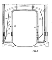
- the air filter housing shown in Figure 1 is designed as a cover for a V-shaped arranged internal combustion engine. It has an outer contour 10, which is the overall housing encloses.
- the plan view shows arranged within the contour 10 plate filter elements 11; 12 below these plate filter elements is the respective Rohlufteinlass.
- the incoming air is passed through the plate filter elements, cleaned and flows into the clean air areas 13; 14. From there, the air becomes the cylinder banks supplied to the internal combustion engine.
- Immediately adjacent to the respective Plate filter element 11; 12 is an area 15; 16 in the little or only a small flow of air takes place. This housing area is conditioned by the outer Contour 10, which is again required for design reasons.
- each is a partition wall 17; 18 provided, this runs approximately parallel to the inner contour 19; 20 and is in the area 21; 22 attached to this inner contour.
- the partition is bent and forms with the Inner contour 19; 20 each have an acoustic neck 23; 24.
- an effective shunt resonator volume arises is the partition 17; 18 not only with the inner contour 19; 20 but also connected to at least two other housing walls.
- the acoustic neck 23; 24 connects to each adjacent one Clean air area 13; 14 dar.
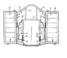
- FIG. 2 shows in a detailed view two further variants of a partition wall 25; 26; same Parts are provided with the same reference numerals.
- the cavity 27 is without the formation of an acoustic neck, the cavity 28 has the peculiarity in that webs 29; 30; 31; 32; 33 which are the acoustic properties of the shunt resonator. These bars can stretch over the entire Extending partition height.
- FIG. 3 shows a system which has a housing 34, this is with a lid 35 lockable.
- a filter element 36 as a plate filter element is constructed and consists of a zig-zag folded filter paper.
- the circumferential seal 37 of the filter element simultaneously seals the cover 35 on the housing 34.
- On the housing 34 is a Rohlufteintritt 38.
- At the Lid 35 is the clean air outlet 39.
- the air to be purified flows through the Raw air inlet 38, flows through the filter element and is cleaned via the outlet 39 fed to an internal combustion engine, not shown here.
- the housing 34 has a pulled down shape with a pot-shaped configuration 40 at which in Bottom area 41 a dust discharge valve 42 is located. Parallel to the bottom 41 is a Partition 43 arranged.
- the partition wall has at least one opening 44 to the Raw air space of the housing 34, this opening is designed such that both with the raw air introduced dust can be supplied to the Staubaustragsventil, as well an acoustic property of the bypass resonator formed by the partition wall is effected.
- the partition wall 45 is arranged to mate with the right side wall of the housing 34 forms a cavity 46 as a shunt resonator.
- a partition but a lambda / 4-tube 50, to provide in the region of the filter housing, which does not flow through the air becomes.
- a lambda / 4 pipe should suitably be near the clean air outlet its Possess openings. At this point, this acoustic means has the best effectiveness.
Abstract
Description
- Figur 1
- Die schematische Darstellung eines Luftfiltergehäuses
- Figur 2
- Eine Detailansicht des in Figur 1 gezeigten Luftfiltergehäuses
- Figur 3
- Eine Variante eines Luftführungssystems
Claims (7)
- Ansaugsystem einer Brennkraftmaschine, bestehend aus einem Rohlufteinlass, einem in einem Gehäuse angeordneten Filterelement, welches den Rohluftbereich des Gehäuses und den Reinluftbereich trennt und einem Reinluftauslass aus dem Gehäuse, welcher mit der Brennkraftmaschine verbunden ist, wobei wenigstens ein Nebenschlussresonator und/oder ein Lambda/4-Rohr vorgesehen ist, dadurch gekennzeichnet, dass der Nebenschlussresonator und/oder das Lambda/4-Rohr die Bereiche des Luftfiltergehäuses ausfüllen, in welchen keine oder nur eine geringe Luftbewegung stattfindet.
- Ansaugsystem nach Anspruch 1, dadurch gekennzeichnet, dass Nebenschlussresonator und/oder Lambda/4-Rohr auf der Rohluftseite und/oder auf der Reinluftseite des Luftfiltergehäuses angeordnet sind.
- Ansaugsystem nach Anspruch 1, dadurch gekennzeichnet, dass der Nebenschlussresonator von einer Außenwand des Luftfiltergehäuses gebildet wird, wobei wenigstens eine Trennwand sich in das Luftfiltergehäuse erstreckt.
- Ansaugsystem nach einem der vorherigen Ansprüche, dadurch gekennzeichnet, dass die Brennkraftmaschine eine V-förmig angeordnete Brennkraftmaschine ist und zwei Luftfiltergehäuse aufweist, wobei diese symmetrisch auf der Brennkraftmaschine angeordnet sind und zwei Nebenschlussresonatoren innerhalb des Luftfiltergehäuses vorgesehen sind.
- Ansaugsystem nach Anspruch 3, dadurch gekennzeichnet, dass die Trennwand mit weiteren schallreduzierenden Elementen wie Stegen oder zusätzlichen Hohlräumen versehen ist.
- Ansaugsystem nach Anspruch 3, dadurch gekennzeichnet, dass sich innerhalb des Nebenschlussresonators ein Staubaustragventil und / oder Wasseraustragventil befindet und dieses an der Außenwand des Luftfiltergehäuses angeordnet ist.
- Ansaugsystem nach einem der vorherigen Ansprüche, dadurch gekennzeichnet, dass der Nebenschlussresonator als Plattenresonator ausgebildet ist.
Applications Claiming Priority (2)
| Application Number | Priority Date | Filing Date | Title |
|---|---|---|---|
| DE102004016478 | 2004-03-31 | ||
| DE102004016478A DE102004016478A1 (de) | 2004-03-31 | 2004-03-31 | Ansaugsystem einer Brennkraftmaschine |
Publications (2)
| Publication Number | Publication Date |
|---|---|
| EP1582734A1 true EP1582734A1 (de) | 2005-10-05 |
| EP1582734B1 EP1582734B1 (de) | 2008-08-13 |
Family
ID=34877715
Family Applications (1)
| Application Number | Title | Priority Date | Filing Date |
|---|---|---|---|
| EP05102301A Not-in-force EP1582734B1 (de) | 2004-03-31 | 2005-03-22 | Ansaugsystem einer Brennkraftmaschine |
Country Status (4)
| Country | Link |
|---|---|
| US (1) | US7165525B2 (de) |
| EP (1) | EP1582734B1 (de) |
| AT (1) | ATE404788T1 (de) |
| DE (2) | DE102004016478A1 (de) |
Cited By (1)
| Publication number | Priority date | Publication date | Assignee | Title |
|---|---|---|---|---|
| EP1895148A1 (de) * | 2006-09-04 | 2008-03-05 | Honda Motor Co., Ltd. | Luftansaugvorrichtung eines Motorrades |
Families Citing this family (6)
| Publication number | Priority date | Publication date | Assignee | Title |
|---|---|---|---|---|
| JP5685422B2 (ja) * | 2010-11-19 | 2015-03-18 | 本田技研工業株式会社 | コージェネレーション装置 |
| DE102011051691A1 (de) * | 2011-07-08 | 2013-01-10 | Dr. Ing. H.C. F. Porsche Aktiengesellschaft | Geräuschübertragungssystem |
| DE102011051689A1 (de) | 2011-07-08 | 2013-01-10 | Dr. Ing. H.C. F. Porsche Ag | Geräuschübertragungssystem |
| JP6247019B2 (ja) * | 2013-05-14 | 2017-12-13 | 株式会社マーレ フィルターシステムズ | エアクリーナ |
| JP5967447B2 (ja) * | 2013-12-10 | 2016-08-10 | 本田技研工業株式会社 | 鞍乗り型車両の吸気装置 |
| AU2017332131A1 (en) | 2016-09-20 | 2019-03-21 | Mtd Products Inc | Air box assembly for an outdoor power tool |
Citations (4)
| Publication number | Priority date | Publication date | Assignee | Title |
|---|---|---|---|---|
| JPS5713262A (en) * | 1980-06-26 | 1982-01-23 | Toyota Motor Corp | Air cleaner for internal combustion engine |
| EP0233809A1 (de) * | 1986-01-24 | 1987-08-26 | Ecia - Equipements Et Composants Pour L'industrie Automobile | Luftfilter, insbesondere für Brennkraftmaschinen |
| EP0379926A1 (de) * | 1989-01-24 | 1990-08-01 | Mazda Motor Corporation | Einlassleitungssystem für Kraftmaschine mit mehreren Zylindern |
| JP2002266715A (ja) * | 2001-03-09 | 2002-09-18 | Mahle Tennex Corp | エアクリーナ |
Family Cites Families (10)
| Publication number | Priority date | Publication date | Assignee | Title |
|---|---|---|---|---|
| JPS6038531B2 (ja) * | 1978-06-16 | 1985-09-02 | 日産自動車株式会社 | 二次空気導入装置 |
| US5140957A (en) * | 1991-07-31 | 1992-08-25 | Walker Robert A | Combination in line air-filter/air-oil separator/air-silencer |
| US5424494A (en) * | 1992-12-10 | 1995-06-13 | Siemens Automotive Limited | Noise-attenuating internal combustion engine air intake system |
| DE4241586C1 (de) * | 1992-12-10 | 1994-01-27 | Mann & Hummel Filter | Luftfilter |
| US5479907A (en) * | 1994-07-12 | 1996-01-02 | Walker, Jr.; Robert A. | Combination in-line air-filter/air-oil separator/air-silencer with preseparator |
| US5853439A (en) * | 1997-06-27 | 1998-12-29 | Donaldson Company, Inc. | Aerosol separator and method |
| DE19962888A1 (de) * | 1999-12-24 | 2001-06-28 | Mahle Filtersysteme Gmbh | Filter, insbesondere Ansaugluftfilter |
| US6394062B2 (en) * | 2000-03-30 | 2002-05-28 | Siemens Canada Limited | Dust sensing assembly air intake system |
| DE10049313A1 (de) * | 2000-10-05 | 2002-04-11 | Audi Ag | Gehäuse zur Aufnahme eines Luftfilterelements |
| US7257942B2 (en) * | 2002-08-23 | 2007-08-21 | Donaldson Company, Inc. | Apparatus for emissions control, systems, and methods |
-
2004
- 2004-03-31 DE DE102004016478A patent/DE102004016478A1/de not_active Ceased
-
2005
- 2005-03-22 EP EP05102301A patent/EP1582734B1/de not_active Not-in-force
- 2005-03-22 AT AT05102301T patent/ATE404788T1/de not_active IP Right Cessation
- 2005-03-22 DE DE502005004984T patent/DE502005004984D1/de active Active
- 2005-03-31 US US11/094,666 patent/US7165525B2/en active Active
Patent Citations (4)
| Publication number | Priority date | Publication date | Assignee | Title |
|---|---|---|---|---|
| JPS5713262A (en) * | 1980-06-26 | 1982-01-23 | Toyota Motor Corp | Air cleaner for internal combustion engine |
| EP0233809A1 (de) * | 1986-01-24 | 1987-08-26 | Ecia - Equipements Et Composants Pour L'industrie Automobile | Luftfilter, insbesondere für Brennkraftmaschinen |
| EP0379926A1 (de) * | 1989-01-24 | 1990-08-01 | Mazda Motor Corporation | Einlassleitungssystem für Kraftmaschine mit mehreren Zylindern |
| JP2002266715A (ja) * | 2001-03-09 | 2002-09-18 | Mahle Tennex Corp | エアクリーナ |
Non-Patent Citations (2)
| Title |
|---|
| PATENT ABSTRACTS OF JAPAN vol. 006, no. 074 (M - 127) 11 May 1982 (1982-05-11) * |
| PATENT ABSTRACTS OF JAPAN vol. 2003, no. 01 14 January 2003 (2003-01-14) * |
Cited By (2)
| Publication number | Priority date | Publication date | Assignee | Title |
|---|---|---|---|---|
| EP1895148A1 (de) * | 2006-09-04 | 2008-03-05 | Honda Motor Co., Ltd. | Luftansaugvorrichtung eines Motorrades |
| US7614380B2 (en) | 2006-09-04 | 2009-11-10 | Honda Motor Co., Ltd. | Intake device for a motorcycle |
Also Published As
| Publication number | Publication date |
|---|---|
| ATE404788T1 (de) | 2008-08-15 |
| DE502005004984D1 (de) | 2008-09-25 |
| US7165525B2 (en) | 2007-01-23 |
| EP1582734B1 (de) | 2008-08-13 |
| US20050217635A1 (en) | 2005-10-06 |
| DE102004016478A1 (de) | 2005-10-20 |
Similar Documents
| Publication | Publication Date | Title |
|---|---|---|
| EP1582734B1 (de) | Ansaugsystem einer Brennkraftmaschine | |
| EP2145099B1 (de) | Kraftstoffzuführeinrichtung, insbesondere für eine brennkraftmaschine | |
| EP2675547A1 (de) | Luftfilterelement, luftfiltergehäuse und luftfiltersystem | |
| EP1500423A1 (de) | Filterzusammenbau des Wirbeltyps | |
| WO2008116508A1 (de) | Filter zur reinigung eines fluids | |
| EP1738068B1 (de) | Fördereinheit | |
| DE10036241A1 (de) | Integriertes Luftansaugmodul für Benzinmotoren | |
| DE102005046810A1 (de) | Abscheider für Flüssigkeiten, insbesondere Kondensat, aus flüssigkeitsbeladenen, komprimierten Gasen | |
| DE4438556A1 (de) | Filter, insbesondere zum Filtrieren der Ansaugluft einer Brennkraftmaschine | |
| DE102004002293A1 (de) | Luftfilter | |
| DE10323792A1 (de) | Vorrichtung zur Reinigung eines Gasstromes | |
| WO2006114205A1 (de) | Filtersystem | |
| DE102010021862B4 (de) | Luftfilter | |
| EP1400685B1 (de) | Resonatorluftfilter | |
| WO2008043610A1 (de) | Filtereinrichtung, insbesondere zur filtration von verbrennungsluft in brennkraftmaschinen | |
| DE102004049446A1 (de) | Vorrichtung zur Absenkung von Strömungsgeräuschen | |
| DE102007031731A1 (de) | Luftfilter zum direkten Anbau an einen Mehrzylinder-Verbrennungsmotor | |
| WO2005098215A1 (de) | Sauganlage für eine brennkraftmaschine | |
| DE3734338A1 (de) | Luftansauggruppe fuer nutzfahrzeuge | |
| DE202007011100U1 (de) | Filterelement | |
| EP1049866B1 (de) | Mit dämpferglied versehenes luftfilter zu brennkraftmaschinen | |
| EP3743190B1 (de) | Filterelement, insbesondere zur gasfiltration | |
| WO2016124258A1 (de) | Modular aufgebautes filterelement eines filtersystems, elementrahmen eines filterelements und filtersystem | |
| DE2251533C3 (de) | ||
| DE202006019934U1 (de) | Filter mit austauschbarem Einsatzteil |
Legal Events
| Date | Code | Title | Description |
|---|---|---|---|
| PUAI | Public reference made under article 153(3) epc to a published international application that has entered the european phase |
Free format text: ORIGINAL CODE: 0009012 |
|
| AK | Designated contracting states |
Kind code of ref document: A1 Designated state(s): AT BE BG CH CY CZ DE DK EE ES FI FR GB GR HU IE IS IT LI LT LU MC NL PL PT RO SE SI SK TR |
|
| AX | Request for extension of the european patent |
Extension state: AL BA HR LV MK YU |
|
| 17P | Request for examination filed |
Effective date: 20051024 |
|
| AKX | Designation fees paid |
Designated state(s): AT BE BG CH CY CZ DE DK EE ES FI FR GB GR HU IE IS IT LI LT LU MC NL PL PT RO SE SI SK TR |
|
| 17Q | First examination report despatched |
Effective date: 20060308 |
|
| GRAP | Despatch of communication of intention to grant a patent |
Free format text: ORIGINAL CODE: EPIDOSNIGR1 |
|
| GRAS | Grant fee paid |
Free format text: ORIGINAL CODE: EPIDOSNIGR3 |
|
| GRAA | (expected) grant |
Free format text: ORIGINAL CODE: 0009210 |
|
| AK | Designated contracting states |
Kind code of ref document: B1 Designated state(s): AT BE BG CH CY CZ DE DK EE ES FI FR GB GR HU IE IS IT LI LT LU MC NL PL PT RO SE SI SK TR |
|
| REG | Reference to a national code |
Ref country code: GB Ref legal event code: FG4D Free format text: NOT ENGLISH |
|
| REG | Reference to a national code |
Ref country code: CH Ref legal event code: EP |
|
| REG | Reference to a national code |
Ref country code: IE Ref legal event code: FG4D Free format text: LANGUAGE OF EP DOCUMENT: GERMAN |
|
| REF | Corresponds to: |
Ref document number: 502005004984 Country of ref document: DE Date of ref document: 20080925 Kind code of ref document: P |
|
| PG25 | Lapsed in a contracting state [announced via postgrant information from national office to epo] |
Ref country code: LT Free format text: LAPSE BECAUSE OF FAILURE TO SUBMIT A TRANSLATION OF THE DESCRIPTION OR TO PAY THE FEE WITHIN THE PRESCRIBED TIME-LIMIT Effective date: 20080813 Ref country code: IS Free format text: LAPSE BECAUSE OF FAILURE TO SUBMIT A TRANSLATION OF THE DESCRIPTION OR TO PAY THE FEE WITHIN THE PRESCRIBED TIME-LIMIT Effective date: 20081213 Ref country code: NL Free format text: LAPSE BECAUSE OF FAILURE TO SUBMIT A TRANSLATION OF THE DESCRIPTION OR TO PAY THE FEE WITHIN THE PRESCRIBED TIME-LIMIT Effective date: 20080813 |
|
| PG25 | Lapsed in a contracting state [announced via postgrant information from national office to epo] |
Ref country code: ES Free format text: LAPSE BECAUSE OF FAILURE TO SUBMIT A TRANSLATION OF THE DESCRIPTION OR TO PAY THE FEE WITHIN THE PRESCRIBED TIME-LIMIT Effective date: 20081124 Ref country code: FI Free format text: LAPSE BECAUSE OF FAILURE TO SUBMIT A TRANSLATION OF THE DESCRIPTION OR TO PAY THE FEE WITHIN THE PRESCRIBED TIME-LIMIT Effective date: 20080813 Ref country code: SI Free format text: LAPSE BECAUSE OF FAILURE TO SUBMIT A TRANSLATION OF THE DESCRIPTION OR TO PAY THE FEE WITHIN THE PRESCRIBED TIME-LIMIT Effective date: 20080813 |
|
| REG | Reference to a national code |
Ref country code: IE Ref legal event code: FD4D |
|
| PG25 | Lapsed in a contracting state [announced via postgrant information from national office to epo] |
Ref country code: IE Free format text: LAPSE BECAUSE OF FAILURE TO SUBMIT A TRANSLATION OF THE DESCRIPTION OR TO PAY THE FEE WITHIN THE PRESCRIBED TIME-LIMIT Effective date: 20080813 Ref country code: BG Free format text: LAPSE BECAUSE OF FAILURE TO SUBMIT A TRANSLATION OF THE DESCRIPTION OR TO PAY THE FEE WITHIN THE PRESCRIBED TIME-LIMIT Effective date: 20081113 Ref country code: DK Free format text: LAPSE BECAUSE OF FAILURE TO SUBMIT A TRANSLATION OF THE DESCRIPTION OR TO PAY THE FEE WITHIN THE PRESCRIBED TIME-LIMIT Effective date: 20080813 |
|
| PG25 | Lapsed in a contracting state [announced via postgrant information from national office to epo] |
Ref country code: RO Free format text: LAPSE BECAUSE OF FAILURE TO SUBMIT A TRANSLATION OF THE DESCRIPTION OR TO PAY THE FEE WITHIN THE PRESCRIBED TIME-LIMIT Effective date: 20080813 Ref country code: PT Free format text: LAPSE BECAUSE OF FAILURE TO SUBMIT A TRANSLATION OF THE DESCRIPTION OR TO PAY THE FEE WITHIN THE PRESCRIBED TIME-LIMIT Effective date: 20090113 Ref country code: CZ Free format text: LAPSE BECAUSE OF FAILURE TO SUBMIT A TRANSLATION OF THE DESCRIPTION OR TO PAY THE FEE WITHIN THE PRESCRIBED TIME-LIMIT Effective date: 20080813 Ref country code: SK Free format text: LAPSE BECAUSE OF FAILURE TO SUBMIT A TRANSLATION OF THE DESCRIPTION OR TO PAY THE FEE WITHIN THE PRESCRIBED TIME-LIMIT Effective date: 20080813 |
|
| PLBE | No opposition filed within time limit |
Free format text: ORIGINAL CODE: 0009261 |
|
| STAA | Information on the status of an ep patent application or granted ep patent |
Free format text: STATUS: NO OPPOSITION FILED WITHIN TIME LIMIT |
|
| 26N | No opposition filed |
Effective date: 20090514 |
|
| PG25 | Lapsed in a contracting state [announced via postgrant information from national office to epo] |
Ref country code: EE Free format text: LAPSE BECAUSE OF FAILURE TO SUBMIT A TRANSLATION OF THE DESCRIPTION OR TO PAY THE FEE WITHIN THE PRESCRIBED TIME-LIMIT Effective date: 20080813 |
|
| PG25 | Lapsed in a contracting state [announced via postgrant information from national office to epo] |
Ref country code: IT Free format text: LAPSE BECAUSE OF FAILURE TO SUBMIT A TRANSLATION OF THE DESCRIPTION OR TO PAY THE FEE WITHIN THE PRESCRIBED TIME-LIMIT Effective date: 20080813 |
|
| BERE | Be: lapsed |
Owner name: MANN+HUMMEL G.M.B.H. Effective date: 20090331 |
|
| PG25 | Lapsed in a contracting state [announced via postgrant information from national office to epo] |
Ref country code: MC Free format text: LAPSE BECAUSE OF NON-PAYMENT OF DUE FEES Effective date: 20090331 |
|
| REG | Reference to a national code |
Ref country code: CH Ref legal event code: PL |
|
| GBPC | Gb: european patent ceased through non-payment of renewal fee |
Effective date: 20090322 |
|
| REG | Reference to a national code |
Ref country code: FR Ref legal event code: ST Effective date: 20091130 |
|
| PG25 | Lapsed in a contracting state [announced via postgrant information from national office to epo] |
Ref country code: SE Free format text: LAPSE BECAUSE OF FAILURE TO SUBMIT A TRANSLATION OF THE DESCRIPTION OR TO PAY THE FEE WITHIN THE PRESCRIBED TIME-LIMIT Effective date: 20081113 Ref country code: LI Free format text: LAPSE BECAUSE OF NON-PAYMENT OF DUE FEES Effective date: 20090331 Ref country code: CH Free format text: LAPSE BECAUSE OF NON-PAYMENT OF DUE FEES Effective date: 20090331 |
|
| PG25 | Lapsed in a contracting state [announced via postgrant information from national office to epo] |
Ref country code: BE Free format text: LAPSE BECAUSE OF NON-PAYMENT OF DUE FEES Effective date: 20090331 |
|
| PG25 | Lapsed in a contracting state [announced via postgrant information from national office to epo] |
Ref country code: GB Free format text: LAPSE BECAUSE OF NON-PAYMENT OF DUE FEES Effective date: 20090322 Ref country code: FR Free format text: LAPSE BECAUSE OF NON-PAYMENT OF DUE FEES Effective date: 20091123 |
|
| PG25 | Lapsed in a contracting state [announced via postgrant information from national office to epo] |
Ref country code: PL Free format text: LAPSE BECAUSE OF FAILURE TO SUBMIT A TRANSLATION OF THE DESCRIPTION OR TO PAY THE FEE WITHIN THE PRESCRIBED TIME-LIMIT Effective date: 20080813 |
|
| PG25 | Lapsed in a contracting state [announced via postgrant information from national office to epo] |
Ref country code: AT Free format text: LAPSE BECAUSE OF NON-PAYMENT OF DUE FEES Effective date: 20090322 |
|
| PG25 | Lapsed in a contracting state [announced via postgrant information from national office to epo] |
Ref country code: GR Free format text: LAPSE BECAUSE OF FAILURE TO SUBMIT A TRANSLATION OF THE DESCRIPTION OR TO PAY THE FEE WITHIN THE PRESCRIBED TIME-LIMIT Effective date: 20081114 |
|
| PG25 | Lapsed in a contracting state [announced via postgrant information from national office to epo] |
Ref country code: LU Free format text: LAPSE BECAUSE OF NON-PAYMENT OF DUE FEES Effective date: 20090322 |
|
| PG25 | Lapsed in a contracting state [announced via postgrant information from national office to epo] |
Ref country code: HU Free format text: LAPSE BECAUSE OF FAILURE TO SUBMIT A TRANSLATION OF THE DESCRIPTION OR TO PAY THE FEE WITHIN THE PRESCRIBED TIME-LIMIT Effective date: 20090214 |
|
| PG25 | Lapsed in a contracting state [announced via postgrant information from national office to epo] |
Ref country code: TR Free format text: LAPSE BECAUSE OF FAILURE TO SUBMIT A TRANSLATION OF THE DESCRIPTION OR TO PAY THE FEE WITHIN THE PRESCRIBED TIME-LIMIT Effective date: 20080813 |
|
| PG25 | Lapsed in a contracting state [announced via postgrant information from national office to epo] |
Ref country code: CY Free format text: LAPSE BECAUSE OF FAILURE TO SUBMIT A TRANSLATION OF THE DESCRIPTION OR TO PAY THE FEE WITHIN THE PRESCRIBED TIME-LIMIT Effective date: 20080813 |
|
| REG | Reference to a national code |
Ref country code: DE Ref legal event code: R081 Ref document number: 502005004984 Country of ref document: DE Owner name: MANN+HUMMEL GMBH, DE Free format text: FORMER OWNER: MANN+HUMMEL GMBH, 71638 LUDWIGSBURG, DE |
|
| PGFP | Annual fee paid to national office [announced via postgrant information from national office to epo] |
Ref country code: DE Payment date: 20200330 Year of fee payment: 16 |
|
| REG | Reference to a national code |
Ref country code: DE Ref legal event code: R119 Ref document number: 502005004984 Country of ref document: DE |
|
| PG25 | Lapsed in a contracting state [announced via postgrant information from national office to epo] |
Ref country code: DE Free format text: LAPSE BECAUSE OF NON-PAYMENT OF DUE FEES Effective date: 20211001 |