EP1586275B1 - Endoscope therapeutic device - Google Patents
Endoscope therapeutic device Download PDFInfo
- Publication number
- EP1586275B1 EP1586275B1 EP05007799.9A EP05007799A EP1586275B1 EP 1586275 B1 EP1586275 B1 EP 1586275B1 EP 05007799 A EP05007799 A EP 05007799A EP 1586275 B1 EP1586275 B1 EP 1586275B1
- Authority
- EP
- European Patent Office
- Prior art keywords
- treatment tool
- introduction guide
- endoscope
- guide tube
- therapeutic device
- Prior art date
- Legal status (The legal status is an assumption and is not a legal conclusion. Google has not performed a legal analysis and makes no representation as to the accuracy of the status listed.)
- Expired - Fee Related
Links
Images


Classifications
-
- A—HUMAN NECESSITIES
- A61—MEDICAL OR VETERINARY SCIENCE; HYGIENE
- A61B—DIAGNOSIS; SURGERY; IDENTIFICATION
- A61B17/00—Surgical instruments, devices or methods, e.g. tourniquets
- A61B17/34—Trocars; Puncturing needles
- A61B17/3417—Details of tips or shafts, e.g. grooves, expandable, bendable; Multiple coaxial sliding cannulas, e.g. for dilating
- A61B17/3421—Cannulas
-
- A—HUMAN NECESSITIES
- A61—MEDICAL OR VETERINARY SCIENCE; HYGIENE
- A61B—DIAGNOSIS; SURGERY; IDENTIFICATION
- A61B1/00—Instruments for performing medical examinations of the interior of cavities or tubes of the body by visual or photographical inspection, e.g. endoscopes; Illuminating arrangements therefor
- A61B1/00064—Constructional details of the endoscope body
- A61B1/00071—Insertion part of the endoscope body
- A61B1/0008—Insertion part of the endoscope body characterised by distal tip features
- A61B1/00087—Tools
-
- A—HUMAN NECESSITIES
- A61—MEDICAL OR VETERINARY SCIENCE; HYGIENE
- A61B—DIAGNOSIS; SURGERY; IDENTIFICATION
- A61B1/00—Instruments for performing medical examinations of the interior of cavities or tubes of the body by visual or photographical inspection, e.g. endoscopes; Illuminating arrangements therefor
- A61B1/00131—Accessories for endoscopes
- A61B1/00133—Drive units for endoscopic tools inserted through or with the endoscope
-
- A—HUMAN NECESSITIES
- A61—MEDICAL OR VETERINARY SCIENCE; HYGIENE
- A61B—DIAGNOSIS; SURGERY; IDENTIFICATION
- A61B1/00—Instruments for performing medical examinations of the interior of cavities or tubes of the body by visual or photographical inspection, e.g. endoscopes; Illuminating arrangements therefor
- A61B1/00131—Accessories for endoscopes
- A61B1/00135—Oversleeves mounted on the endoscope prior to insertion
-
- A—HUMAN NECESSITIES
- A61—MEDICAL OR VETERINARY SCIENCE; HYGIENE
- A61B—DIAGNOSIS; SURGERY; IDENTIFICATION
- A61B1/00—Instruments for performing medical examinations of the interior of cavities or tubes of the body by visual or photographical inspection, e.g. endoscopes; Illuminating arrangements therefor
- A61B1/012—Instruments for performing medical examinations of the interior of cavities or tubes of the body by visual or photographical inspection, e.g. endoscopes; Illuminating arrangements therefor characterised by internal passages or accessories therefor
- A61B1/018—Instruments for performing medical examinations of the interior of cavities or tubes of the body by visual or photographical inspection, e.g. endoscopes; Illuminating arrangements therefor characterised by internal passages or accessories therefor for receiving instruments
-
- A—HUMAN NECESSITIES
- A61—MEDICAL OR VETERINARY SCIENCE; HYGIENE
- A61B—DIAGNOSIS; SURGERY; IDENTIFICATION
- A61B17/00—Surgical instruments, devices or methods, e.g. tourniquets
- A61B2017/00367—Details of actuation of instruments, e.g. relations between pushing buttons, or the like, and activation of the tool, working tip, or the like
- A61B2017/00398—Details of actuation of instruments, e.g. relations between pushing buttons, or the like, and activation of the tool, working tip, or the like using powered actuators, e.g. stepper motors, solenoids
-
- A—HUMAN NECESSITIES
- A61—MEDICAL OR VETERINARY SCIENCE; HYGIENE
- A61B—DIAGNOSIS; SURGERY; IDENTIFICATION
- A61B17/00—Surgical instruments, devices or methods, e.g. tourniquets
- A61B17/28—Surgical forceps
- A61B17/29—Forceps for use in minimally invasive surgery
- A61B2017/2901—Details of shaft
- A61B2017/2905—Details of shaft flexible
-
- A—HUMAN NECESSITIES
- A61—MEDICAL OR VETERINARY SCIENCE; HYGIENE
- A61B—DIAGNOSIS; SURGERY; IDENTIFICATION
- A61B17/00—Surgical instruments, devices or methods, e.g. tourniquets
- A61B17/28—Surgical forceps
- A61B17/29—Forceps for use in minimally invasive surgery
- A61B2017/2901—Details of shaft
- A61B2017/2906—Multiple forceps
-
- A—HUMAN NECESSITIES
- A61—MEDICAL OR VETERINARY SCIENCE; HYGIENE
- A61B—DIAGNOSIS; SURGERY; IDENTIFICATION
- A61B17/00—Surgical instruments, devices or methods, e.g. tourniquets
- A61B17/28—Surgical forceps
- A61B17/29—Forceps for use in minimally invasive surgery
- A61B2017/2926—Details of heads or jaws
- A61B2017/2927—Details of heads or jaws the angular position of the head being adjustable with respect to the shaft
- A61B2017/2929—Details of heads or jaws the angular position of the head being adjustable with respect to the shaft with a head rotatable about the longitudinal axis of the shaft
-
- A—HUMAN NECESSITIES
- A61—MEDICAL OR VETERINARY SCIENCE; HYGIENE
- A61B—DIAGNOSIS; SURGERY; IDENTIFICATION
- A61B17/00—Surgical instruments, devices or methods, e.g. tourniquets
- A61B17/34—Trocars; Puncturing needles
- A61B17/3417—Details of tips or shafts, e.g. grooves, expandable, bendable; Multiple coaxial sliding cannulas, e.g. for dilating
- A61B17/3421—Cannulas
- A61B2017/3445—Cannulas used as instrument channel for multiple instruments
-
- A—HUMAN NECESSITIES
- A61—MEDICAL OR VETERINARY SCIENCE; HYGIENE
- A61B—DIAGNOSIS; SURGERY; IDENTIFICATION
- A61B17/00—Surgical instruments, devices or methods, e.g. tourniquets
- A61B17/34—Trocars; Puncturing needles
- A61B2017/347—Locking means, e.g. for locking instrument in cannula
-
- A—HUMAN NECESSITIES
- A61—MEDICAL OR VETERINARY SCIENCE; HYGIENE
- A61B—DIAGNOSIS; SURGERY; IDENTIFICATION
- A61B34/00—Computer-aided surgery; Manipulators or robots specially adapted for use in surgery
- A61B34/70—Manipulators specially adapted for use in surgery
Definitions
- the present invention relates to an endoscope therapeutic device for performing treatment under observation via an endoscope by introducing a treatment tool through an introduction guide tube with a bending function into a body cavity, and an introduction guide tube thereof.
- An endoscope therapeutic device for performing treatment using a treatment tool under observation via an endoscope by introducing the treatment tool through an introduction guide tube into a body cavity is known in the related art.
- the introduction guide tube used in the endoscope therapeutic device of this type is referred also as a "channel tube”.
- an introduction guide tube of this type an introduction guide tube with a bending function, in which a bending portion is provided in the vicinity of the distal end of the tube, and the bending portion is capable of being bent by a proximal control section is proposed (See JP-A-2000-33071 ).
- This endoscope therapeutic device is configured in such a manner that treatment tools are guided via a plurality of introduction guide tubes with a bending function, respectively, into a body cavity, and the directions of the treatment tools in the body cavity are adjusted by bending the bending portions of the introduction guide tubes.
- US 6,066,090 discloses a two-branch endoscope including a first endoscope branch and a second endoscope branch. Each branch is separately steerable and the first endoscope branch may be used to view the distal end of the second endoscope branch.
- Each endoscope branch includes an illumination source, an image receiver and an operating channel.
- Each endoscope branch may also be independently adjusted to the range of angles of a selectable sweep of azimuth and may be steered to assume a small radius curl or may be steered in a large radius curl.
- US 6,071,233 discloses an endoscope having a main body and a channel tube provided on the exterior of the main body.
- the main body of the endoscope consists of an insert and a proximal control section.
- the insert is constituted of a distal end portion, a bendable portion, and a flexible tube portion arranged sequentially from the distal end side.
- An observation window is formed in the distal end face.
- the external channel tube is a flexible tube member thinner in diameter than the insert and therefore capable of bending relatively flexible.
- the channel tube is set longitudinally along the insert of the endoscope and in contact with the upper face portion thereof. A tube sheath of a basket-type foreign-body removing tool is inserted into the channel tube.
- Patent Abstracts of Japan JP 2000-033071 A discloses an endoscope therapeutic device comprising an endoscope having an insertion implement part and that executes the therapy of the intra-coeliac section by a treatment implement to be used in combination with this endoscope.
- the device has a regulating means for regulating the relative distance between both of the insertion part for at least either of the treatment implement to be inserted in juxtaposition on the outer side of the insertion part of the endoscope and an insertion implement for guiding the insertion part of the endoscope to the desired position near the front end of the insertion part of the endoscope.
- the two-part from of claim 1 is based on this document.
- Laparoscopic stretching instrument involves the piercing of the abdominal wall and the insertion of a tubular port member or laparoscopic cannula through the perforation.
- Spring loaded locking pins are provided on two shafts for cooperating with apertures in a sleeve to alternately lock the respective shaft in a retracted neutral position and an extended use position.
- An exemplary endoscope therapeutic device includes a plurality of introduction guide tubes for introducing treatment tools into a body cavity, wherein the plurality of introduction guide tubes are joined to each other at portions proximal to the bending portions thereof. In a case where there are a plurality of bending portions on the introduction guide tube, a joint portion is placed in a more proximal position than the distal-most bending portion.
- the form of joint may be such that a part of the insertion portion that is located on a more proximal side than the bending portion of the introduction guide tube is integrally joined with other introduction guide tubes. In this case, a stable connection is achieved. It is also possible to join the introduction guide tubes with a joint tool. In this case, since the introduction guide tubes can be replaced, it is applicable to various embodiments. It is also possible to provide a connecting function to an over tube through which the introduction guide tubes are inserted.
- the positions of the endoscope, a suction tube, and the like in the body cavity are also stabilized by being joined as a matter of course.
- an operating mechanism for operating the distal end of the treatment tool to be inserted therethrough may preferably be provided at the distal end of the introduction guide tube. Since the introduction guide tube is provided with a function to operate the treatment tool in addition to the function to receive the treatment tool inserted therethrough, operability is improved. Since the treating portion and an element moved by operation are located close to each other, a delicate operation can be performed.
- the operator can operate the treatment tools inserted through the guide tubes without releasing his/her hand from the guide tube by operating on the proximal side of the guide tube, and hence good operability is achieved.
- the operation of the treatment tool includes, for example, the fore-and-aft movement or the rotation of the treatment tool.
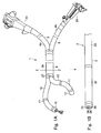
- FIG. 1A is a perspective view of an endoscope therapeutic device according to the first embodiment of the present invention.
- a treatment tool introduction guide tube unit 1 is shown in Fig. 1A.
- Fig. 1B shows an insertion portion 3 of an endoscope 2.
- the treatment tool introduction guide tube unit 1 is joined to the insertion portion 3 of the endoscope 2 by the joint tool described above.
- the treatment tool introduction guide tube unit 1 includes a plurality of treatment tool introduction guide tubes 4a, 4b as manipulators for operating the surgical operation tools including the treatment tools such as forceps or the like.
- the treatment tool introduction guide tubes 4a, 4b are joined at a midsection of an insertion portion 5 thereof by a joint portion 6, and is fixed and joined integrally.
- a joint hood 26, which constitutes the joint portion 6 is formed of a flexible material.
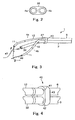
- a mode for joining the two treatment tool introduction guide tubes 4a, 4b by the joint hood 26 is shown in Fig. 2 .
- at least the joint portion 6 can be configured in such a manner.
- a fixed structure in which the insertion portions 5 of a plurality of the treatment tool introduction guide tubes 4a, 4b are connected integrally to each other is provided.
- Fig. 6 is a perspective view of the treatment tool introduction guide tube 4a (4b).
- the insertion portions 5 of the treatment tool introduction guide tubes 4a, 4b each include a distal portion 10 located at a distal end thereof, a first bending portion 11 is located on the proximal side of the distal portion 10, a second bending portion 12 is located on the proximal side of the first bending portion 11, and a flexible portion 13 is provided behind the second bending portion 12.
- a proximal control section 20 is provided at the proximal end of the insertion portion 5 of each of the treatment tool introduction guide tubes 4a or 4b.
- the proximal control sections 20 each include a grip portion 21, an insertion port 22 which communicates with a treatment tool guiding channel 14 (see Fig. 7 ), and a plurality of operating members for bending the bending portions 11, 12 respectively.
- the operating member for bending includes two angle knobs 23a, 23b for operating the first bending portion 11 in two directions and one angle handle 24 for operating the second bending portion 12 in a single (e.g., vertical) direction.
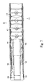
- Fig. 7 is a vertical cross-sectional view of the insertion portion 5 of the treatment tool introduction guide tube in the treatment tool introduction guide tube unit.
- a flexible tube 15 forming the treatment tool guiding channel 14 is disposed over the entire length in the insertion portion 5 of each of the treatment tool introduction guide tubes 4a, 4b.
- the treatment tool guiding channel 14 opens toward the outside at the distal extremity of the insertion portion 5 via a channel hole 16 at the distal portion 10 and at the control section at the insertion port.
- the first bending portion 11 includes a plurality of bending elements 17 joined so as to be capable of rotating freely to allow bending in the vertical and lateral directions, and is bent in the pulling direction of an operating wire 18 by pulling a plurality of the operating wires 18.
- the second bending portion 12 (see Fig. 6 ) also has the same configuration to be bent by means of a plurality of the bending pieces, the second bending portion 12 is configured so as to be bent only in the vertical direction.
- the second bending portion 12 is provided so as to extend or project from the distal end of the joint portion 6.
- the proximal portions in the movable sections including the bending portions 11, 12 are fixedly supported by the joint hood 26.
- a fixing portion fixing means for fixing the portions of the treatment tool introduction guide tubes 4a, 4b in the vicinity of the proximal ends of the bending portions 11, 12 respectively, and then fixing the same to each other is provided.
- the joint hood 26 constitutes a therapeutic instrument joint tool for joining a plurality of the treatment tool introduction guide tubes 4a, 4b.
- the distal end of the joint hood 26 which supports both of the movable sections of the respective treatment tool introduction guide tubes 4a, 4b serves as a common fulcrum 27. Therefore, the movable sections including the bending portions 11, 12 can move respectively on the basis of the common fulcrum 27.
- the fulcrum 27 is also a common fixed point for the movable sections of the respective treatment tool introduction guide tubes 4a, 4b.
- Fig. 1B is a perspective view of the insertion portion 3 of the endoscope 2.
- the insertion portion 3 of the endoscope 2 includes a distal portion 31 located at a distal extremity thereof, a bending portion 32 located on the proximal side of the distal portion 31, and a flexible portion 33 located on the proximal side of the bending portion 32.
- the endoscope 2 has an observation function by the provision of an inspection window 34, an illumination window 35, and a channel port 36 at the distal end surface of the distal portion 31.
- the bending portion 32 is bent by a control section (not shown) provided at a proximal end of the insertion portion 3.
- Fig. 3 is an explanatory drawing showing the state of usage of the endoscope therapeutic device 1 including the treatment tool introduction guide tubes 4a, 4b and the endoscope 2 assembled together according to the first embodiment.
- the treatment tool introduction guide tube unit 1 is joined to the insertion portion 3 of the endoscope 2 by a joint tool 40 in a state of being placed along the insertion portion 3 of the endoscope 2.
- the joint tool 40 is disposed in the vicinity of the distal end of the flexible portion 33 averting the bending portion 32 of the endoscope 2.
- the movable sections of the respective treatment tool introduction guide tubes 4a, 4b including the bending portions 11, 12 are disposed corresponding to the bending portion 32 of the endoscope 2, and are configured to be movable with respect to each other.
- the joint tool 40 includes a band member 43 having an insertion hole 41 for allowing the joint portion 6 of the treatment tool introduction guide tube unit 1 to be inserted therethrough and an insertion hole 42 for allowing the insertion portion 3 of the endoscope 2 to be inserted therethrough, and the band member 43 is capable of opening and closing so that one end can be opened about a hinge 44 on the other end.
- a projection 45 is formed on one of the edges at the openable end of the band member 43 and a corresponding hole 46 for receiving the projection 45 for engagement is formed on the other edge.
- the operator assembles the treatment tool introduction guide tube unit 1 to the insertion portion 3 of the endoscope 2 and guides the same into a body cavity as one unit.
- the operator assembles the treatment tool introduction guide tube unit 1 to the insertion portion 3 of the endoscope 2 and guides the same into a body cavity as one unit.
- a trocar or an over tube (not shown) as a guiding member as is known in the art.
- the operator introduces the various treatment tools (including a suction tool) into the body cavity via the respective treatment tool introduction guide tubes 4a, 4b of the treatment tool introduction guide tube unit 1, which are joined to the insertion portion 3 of the endoscope 2, while observing the body cavity by the endoscope 2 to perform a required treatment. It is also possible to introduce another treatment tool through the channel port 36 and corresponding channel provided on the endoscope 2 to perform a treatment simultaneously.
- Fig. 3 shows a state in which tissue 47 is pulled upward.
- the operator pulls up the tissue 47 using grasping forceps 48 introduced through one of the treatment tool introduction guide tubes 4a, holds the tissue 47 using the grasping forceps 49 introduced through the other introduction guide tube 4b, and moves the respective treatment tools in the opposite direction.
- the operator bends the bending portions 11, 12 of the treatment tool introduction guide tubes 4a, 4b respectively, and provides the opposite movements to the two pairs of forceps 48, 49 to pull the tissue 47.
- the movable sections of the respective treatment tool introduction guide tubes 4a, 4b which guide the respective grasping forceps 48, 49 move in the opposite directions with reference to the fulcrum 27, supporting forces exerted to the fulcrum 27 are mutually invalidated (canceled), and the movable sections of the respective treatment tool introduction guide tubes 4a, 4b move with reference to the fulcrum 27.
- the fulcrum 27 is approximately considered as a fixed point. Therefore, a force to be exerted to the grasping forceps 48, 49 does deviate and can be exerted to the tissue 47 as is. Such behavior is not limited to the case of puling up the tissue 47, but may be the same in the surgical operation such as to expand the tissue 47.
- the flexible portion of the insertion portion is suspended in a space of the body cavity by the reaction received from the grasping forceps so as to be capable of moving freely. Therefore, a force exerted to the tissue can become extremely small because the force generated by the reaction is absorbed in the flexible insertion portion.
- the movable sections of the respective treatment tool introduction guide tubes 4a, 4b which guide the grasping forceps 48, 49 is fixedly supported by the common fulcrum 27, the supporting forces generated by the reaction and exerted to the fulcrum 27 are mutually invalidated at the fulcrum 27, whereby relatively stable support of the movable sections of the treatment tool introduction guide tubes 4a, 4b is achieved.
- the fulcrum 27 can be regarded as a fixed point, and hence the grip forceps 48, 49 can be guided as intended with reference to the fulcrum 27 to perform a quick operation of treatment.
- treatment can be performed with a strong force without any undesirable movement of the treatment tool introduction guide tubes 4a, 4b and/or the endoscope 2.
- the treatment tool introduction guide tube unit 1 is used by being joined to the insertion portion 3 of the endoscope 2 .
- the same advantages can be achieved in the case in which the treatment tool introduction guide tube unit 1 having a plurality of the treatment tool introduction guide tubes joined to each other is used independently.
- the treatment tool introduction guide tube unit 1 is used by being joined to the insertion portion 3 of the endoscope 2, the positional relation with respect to the endoscope 2 is established during use, and hence the surgical situation can be observed easily, and the stable supporting balance is provided to the entire unit, whereby stability of operation is increased, thereby improving usability.
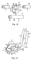
- Fig. 8 is a partial perspective view of the endoscope therapeutic device according to the second embodiment of the present invention.
- the treatment tool introduction guide tube unit 1 according to the second embodiment is an assembly of the two treatment tool introduction guide tubes 4a, 4b integrally inserted through an over tube 61 formed of flexible material.
- the treatment tool introduction guide tubes 4a, 4b are the same as those in the first embodiment.
- Fig. 9 is a perspective view showing the over tube 61 of the endoscope therapeutic device according to the second embodiment
- Fig. 10 is a lateral cross-sectional view of a fixed portion of the treatment tool introduction guide tube built in the over tube 61.
- the over tube 61 is formed with two insertion holes 62a, 62b for inserting the respective two treatment tool introduction guide tubes 4a, 4b separately in a juxtaposed manner.
- the respective insertion holes 62a, 62b are partitioned by a partitioning wall 63 for guiding the treatment tool introduction guide tubes 4a, 4b separately, the insertion holes 62a, 62b partly communicate with each other and are formed close to each other.
- a fixing screw 64 is screwed into a sidewall of one of the insertion holes 62b, and the treatment tool introduction guide tube 4b inserted through the insertion hole 62b is tightened by the screw 64, so that the treatment tool introduction guide tube 4b can be fixed.
- the treatment tool introduction guide tube 4a inserted through the other insertion hole 62a is tightened by resilient deformation of the over tube 61, which occurs when the treatment tool introduction guide tube 4b is tightened by the screw 64, and is fixed to the insertion hole 62b thereby.
- the fixing portion (fixing means) for fixing the portions of the treatment tool introduction guide tubes 4a, 4b in the vicinity of the proximal ends of the bending portions 11, 12 respectively and then fixing the same to each other is provided.
- the over tube 61 itself constitutes the treatment equipment joint tool for joining a plurality of the treatment tool introduction guide tubes 4a, 4b.
- FIG. 11 is an explanatory drawing showing the state of usage of the endoscope therapeutic device.
- the operator mounts the two treatment tool introduction guide tubes 4a, 4b to the over tube 61 respectively to form a single unit, and guides the same into the body cavity using the guide means such as trocar.
- the guide means such as trocar.
- the treatment tool introduction guide tubes 4a, 4b projecting from the distal end of the over tube 61 are retained with the distal end of the over tube 61 as the fulcrum 27, the movement of the treatment tool introduction guide tubes 4a, 4b is stable and smooth.
- the movable operating sections of the treatment tool introduction guide tubes 4a, 4b move with reference to the fulcrum 27, and hence the force exerted to the grasping forceps 48, 49 can be exerted to the tissue 47 without dissipation.
- the operator can fix the portion in the vicinity of the boundary between the first bending portion 11 and the second bending portion 12 onto the over tube 61 by means of the screw 64 or the like with the sections of the second bending portions 12 of the respective treatment tool introduction guide tubes 4a, 4b positioned within the over tube 61 and with only the first bending portion 11 projected from the over tube 61.
- only the first bending portion 11 is bent about the portion in the vicinity of the boundary between the first bending portion 11 and the second bending portion 12 is set as a fulcrum.
- the present invention is not limited to the portion in the vicinity of the proximal end of the proximal-most second bending portion 12, but may take a form in which the portion located at the midsection of the bending portion is fixed.
- the endoscope 2 is provided separately from the unit, and as shown in Fig. 11 , the endoscope 2 can be guided in the body cavity 65 along the over tube 61 of the unit for observing the state of treatment, or can guide a treatment tool such as a separate electrosurgical knife 66.
- Fig. 11 shows a state of incising the tissue 47, which is pulled up by the grasping forceps 48, 49, by means of the electrosurgical knife 66 introduced through the endoscope 2.
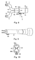
- the third embodiment is configured in such a manner that the above-described two treatment tool introduction guide tubes 4a, 4b and the endoscope 2 are joined by a joint tool 71.
- the joint tool 71 includes a resilient member 75 having a hole portion 72 for fitting the insertion portion 5 of the treatment tool introduction guide tube 4a, a hole portion 73 for fitting the insertion portion 5 of the treatment tool introduction guide tube 4b, and a hole portion 74 for fitting the insertion portion 3 of the endoscope 2 disposed radially.
- the hole portions 72, 73, 74 of the joint tool 71 each are formed with a slit 76 for allowing the member to be put in or removed at the midsection thereof by deforming the portions of the resilient member 75 proximate to the slits 76 to insert the respective insertion portions of the treatment tool introduction guide tubes 4a, 4b and endoscope 2.
- Fig. 13 shows the state of usage of the third embodiment.
- the insertion portion 5 of the treatment tool introduction guide tube 4a, the insertion portion 5 of the treatment tool introduction guide tube 4b, and the insertion portion 3 of the endoscope 2 are mounted by being fitted to the hole portions 72, 73, 74 of the joint tool 71 corresponding thereto, respectively.
- the joint tool 71 is mounted and fixed to the distal portion 31 of the endoscope 2.
- the supporting portion serves as the fulcrum 27 of the treatment tool introduction guide tubes 4a, 4b. Therefore, as shown in Fig.
- the treatment tool introduction guide tubes 4a, 4b and the endoscope 2 are connected by the joint tool 71, the treatment tool introduction guide tubes 4a, 4b are disposed at the position surrounding, and in the vicinity of, the insertion portion 3 of the endoscope 2. Consequently, the same usage as the second embodiment described above is enabled.
- the joint tool 71 may also be disposed at other positions of the endoscope 2 and/or treatment tool introduction guide tubes 4a, 4b.
- An over tube 80 having a bending function is employed in the fourth embodiment.
- the distal portion of the over tube 80 includes a bending portion 81, and the bending portion 81 is bent by the control section (not shown) disposed on a proximal side of the over tube 80.
- the over tube 80 is formed with a hole 83 for receiving an introduction guide tube 82 inserted therethrough, two holes 85 for receiving two respective suction tubes 84a, 84b separately and a hole 86 for receiving the insertion portion 3 of the endoscope 2 in a sectional manner.
- the over tube 80 includes a fixed portion in the vicinity of the distal portion thereof, so that the inserted tools can be supported so that the relative position between the over tube 80 and the inserted tools does not change in the radial direction.
- the introduction guide tube 82 and the suction tubes 84a, 84b are mounted to the over tube 80 so as to be capable of moving in the fore-and-aft direction without wobbling in the radial direction.
- the movable sections of the introduction guide tube 82 and the suction tubes 84a, 84b projecting from the distal end of the over tube 80 are formed with bending portions 87 which are similar to that described above with regard to the treatment tool introduction guide tubes 4a, 4b.
- the proximal portions of the bending portions 87 projecting from the distal end of the over tube 80 are supported by the over tube 80, and the portions of the over tube 80 in the vicinity of the distal end serves as a fulcrum of the movable sections projecting forward therefrom.
- the operator causes the introduction guide tube 82, the suction tubes 84a, 84b, and the insertion portion 3 of the endoscope 2 to project from the distal end of the over tube 80. Then, for example, the distal ends of the two suction tubes 84a, 84b are placed on the tissue 47 to adsorb the tissue 47. The operator can also bend the bending portion 87 of the suction tubes 84a, 84b which are projected from the distal end of the over tubes 80 as needed and pull the tissue 47 upward. The operator can also expand the tissue 47 by bending the bending portions 87 of the suction tubes 84a, 84b, which are projected from the distal end of the over tube 80, as needed in the directions away from each other.
- the reaction forces exerted to the suction tubes 84a, 84b are mutually invalidated, so that the suction tubes 84a, 84b can be operated reliably with a strong force as intended about the distal end of the over tube 80 as the fulcrum.
- the treatment tools may be projected from the introduction guide tube 82 for treatment.
- the introduction guide tube 82 may be used as the suction tube.
- the suction tubes 84a, 84b may be replaced by the treatment tool introduction guide tubes, which are similar to that described above.
- FIG. 15 the endoscope therapeutic device according to a fifth exemplary embodiment be described.
- the same parts as in the embodiments described above are represented by the same reference numerals for description.
- an over tube 90 is employed.
- the over tube 90 is formed integrally with a plurality of manipulators 91a, 91b at the distal end of the over tube 90.
- One of the manipulators 91a is provided with a distal operating section 92 having flexibility, which is similar to the movement of the fingers of a human being, and the other manipulator 91b is provided with a bending portion 93 with the bending function having flexibility which is similar to the movement of the wrist or elbow of a human being.
- the respective manipulators 91a, 91b are separately and remotely operated by an operation input means (not shown).
- the operation input means may be, for example, a glove-type input device to which the movement of the hand of the human being is input and mimicked by the manipulators 91a, 91b.
- the over tube 90 is formed with an insertion channel 95 to which the insertion portion 3 of the endoscope 2 is introduced.
- the endoscope 2 used here has an extra thin insertion portion 3 having only an observing function.
- the operator When using the endoscope therapeutic device, as shown in Fig. 15 , the operator performs treatment by gripping the treatment tool or by nipping the tissue directly using the left and right manipulators 91a, 91b which have flexibility similar to the movement of the fingers of the human being.
- the operability can further be improved, and the usage can be acquired easily.
- the left and right manipulators 91a, 91b are mounted to the distal end of the over tube 90, and fixedly and integrally supported. Accordingly, this supporting portion serves as the fulcrum of the manipulators 91a, 91b as the movable sections. Therefore, in the case of operating in the opposite directions using the respective manipulators 91a, 91b, the forces exerted to the respective manipulators 91a, 91b are mutually invalidated so that the respective manipulators 91a, 91b can be operated reliably with a strong force as intended about the distal end of the over tube 90 as the fulcrum.
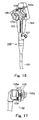
- an introduction guide tube 100 in this therapeutic device includes a flexible insertion portion 101 and a control section 102, and the control section 102 includes a grip portion 103, a plurality of angle knobs 105 for bending the bending portion of the insertion portion 101, an insertion port 107 that communicates with a channel of the insertion portion 101, and a treatment tool operating lever 109 for operating a treatment tool operating mechanism, described later.
- the angle knob 105 is provided with a brake knob 105a for locking the operating position thereof.
- the brake knob may be provided also on the treatment tool operating lever 109.
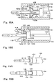
- Fig. 18A and Fig. 18B are vertical cross-sectional views of a distal end of the introduction guide tube in the endoscope therapeutic device according to the sixth embodiment.
- an insertion portion 110a of a treatment tool 110 such as grasping forceps, is inserted from the insertion port 107 of the control section 102 of the introduction guide tube 100 through a channel 106, so as to be projected into the body cavity from an opening 106a at the distal end of the channel 106.
- a treatment tool operating mechanism 108 is built in the distal portion of the insertion portion 101.
- the treatment tool operating mechanism 108 here includes a ring-shaped movable element 115 which allows insertion of the insertion portion 110a of the treatment tool 110 in the distal portion of the insertion portion 101 so as to be capable of linear movement in the fore-and-aft axial direction.
- the distal end of an operating wire 116 inserted through the insertion portion 110 is connected to the movable element 115.
- a movement control mechanism in which the operating wire 116 is moved in the fore-and-aft axial direction when the treatment tool operating lever 109 of the above-described control section 102 is operated, whereby the movable element 115 of the treatment tool operating mechanism 108 is moved in the fore-and-aft direction and the distal end 110a of the treatment tool 110 is moved in the fore-and-aft direction, is configured.
- the movable element 115 constitutes a mechanism for selectively engaging and disengaging grip arms 117 as engaging members that engage part of the insertion portion 110a of the treatment tool 110 by the operating wire 116, which is operated on the proximal side.
- the distal portions of the respective grip arms 117 are resiliently biased so as to open outwardly in the free state shown in Fig. 18B .
- Each grip arm 117 is integrally formed with a holding portion 118 at the distal end thereof.
- a tightening member 121 is attached on the outside of each grip arm 117, and the tightening member 121 is capable of sliding freely in the range between the movable element 115 and the holding portion 118.
- the insertion portion 101 is formed with a guide rail 122 in the distal portion so as to guide the tightening member 121 linearly in the fore-and-aft direction.
- Positioning stoppers (stepped portions) 123a, 123b formed of walls extending vertically upward are formed at the front end and the rear end of the guide rail 122, so that front and rear terminal positions of movement of the tightening member 121 are defined respectively.
- the tightening member 121 includes a sliding portion 124 to be guided by the guide rail 122 and a fastening ring portion 125 that slides on the outer periphery of the grip arm 117. As shown in Fig. 18A , when the tightening member 121 is retracted, the respective grip arms 117 are tightened by the tightening member 121, and the holding portions 118 of the respective grip arms 117 are pressed against the outer periphery of the insertion portion 110a of the treatment member 110 to grip the treatment tool 110 by the movable element 115.
- the treatment tool 110 can be moved in the fore-and-aft direction together with the movable element 115.
- the tightening member 121 When the tightening member 121 is moved forward as shown in Fig. 18B , the distal portions of the respective grip arms 117 open and release the treatment tool 110. In other words, the holding portions 118 of the respective grip arms 117 retract from the insertion portion 110a of the treatment tool 110 and release the treatment tool 110 from the gripped state shown in Fig. 18A . Therefore, the treatment tool 110 can be moved in the fore-and-aft direction or in the rotational direction independently of the introduction guide tube 100, whereby the operability of the treatment tool 110 is improved.
- the introduction guide tube 100 is used as the introduction guide tube in the device in the therapeutic system described above, and can be used for introduction of various treatment tools. It can also be applied to an unit form in which a plurality of the introduction guide tubes 100 are joined so that the supporting forces exerted to the movable sections of a plurality of the introduction guide tubes 100 are mutually invalidated at the common fulcrum.
- the general existing introduction guide tube is simply used for inserting the treatment tool therethrough.
- the treatment tool 110 can be rotated or moved in the fore-and-aft direction positively, and hence the reliable operation of the treatment tool 110 is achieved.
- the introduction guide tube 100 guarantees beneficial effects also when using the introduction guide tube 100 independently and separately from the endoscope 2.
- An introduction guide tube 130 of this type differs from the above-described introduction guide tube 100 in that there is provided a treatment tool advancing-retracting mechanism.
- the treatment tool advancing-retracting mechanism supports a separate extremity member 132 at the distal portion 131 of the introduction guide tube 130 via a plurality of push rods 133 so as to be capable of moving in the fore-and-aft direction.
- the push rods 133 are moved in the fore-and-aft direction by operating the treatment tool operating lever 109 provided on the control section 102 of the introduction guide tube 130, so that the extremity member 132 is moved in the fore-and-aft direction.
- Fig. 19A shows a state in which the extremity member 132 is waiting at a normal position which is retracted backward
- Fig. 19B shows a state in which the extremity member 132 is moved forward.
- a ring-shaped resilient member 135 as the resilient member is disposed at the peripheral edge of the distal end opening of the channel formed on the extremity member 132.
- the ring-shaped resilient member 135 is used for gripping the insertion portion of the treatment tool 110 projected from the distal end opening of the channel by tightening the same with a resilient force.
- the treatment tool 110 is retained by the resiliently tightening force of the ring-shaped resilient member 135 and hence follows the movement of the extremity member 132.
- the force that retains treatment tool 110 is such that when the insertion portion 110a of the treatment tool 110 is pushed and pulled from the proximal side, only the treatment tool 110 can move against the retaining force of the ring-shaped resilient member 135. It is also possible to retain the treatment tool 110 with a force of a strength that cannot move the treatment tool 110.
- the above-described introduction guide tube 130 can also be used as the above-described introduction guide tube and as a member for introducing the treatment tool as a matter of course, and it can also be applied to a unit form in which a plurality of the introduction guide tubes 130 are joined so that the supporting forces exerted to the movable sections of a plurality of the introduction guide tubes 130 are mutually invalidated at the common fulcrum.
- the introduction guide tube 140 includes a flexible insertion portion 141 and a control section 142.
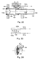
- the control section 142 includes a grip portion 143, a plurality of angle knobs 145 for bending a bending portion 144 (see Fig. 21 ) of the insertion portion 141, an insertion port 147 in communication with a channel 146 (see Fig. 22 ) of the insertion portion 141, a treatment tool rotating knob 149 for operating a treatment tool rotating mechanism 148 described later.
- the angle knob 145 and the treatment tool rotating lever 149 are provided with brake knobs 145a, 149a for locking the operating positions thereof.
- the control section 142 is provided with an operating button 137 for performing operations such as suction or air supply using the channel 146.
- a treatment tool 150 such as the grip forceps from the insertion port 147 of the control section 142 of the introduction guide tube 140 through the channel 146, the treatment tool 150 is projected from a distal end opening of the channel 146 into the body cavity.
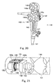
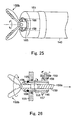
- the treatment tool rotating mechanism 148 is assembled in the distal portion of the insertion portion 141, and is configured as shown in Fig. 21 to Fig. 26 .
- a cylindrical connecting mouth ring 153 to which the distal end of a tube 152 defining the channel 146 is connected, is provided in a distal portion 151 of the insertion portion 141 of the introduction guide tube 140, and the connecting mouth ring 153 is fixed to a supporting member 154 fixed to the distal portion 151.
- a cylindrical connecting mouth ring 153 to which the distal end of a tube 152 defining the channel 146 is connected, is provided in a distal portion 151 of the insertion portion 141 of the introduction guide tube 140, and the connecting mouth ring 153 is fixed to a supporting member 154 fixed to the distal portion 151.
- a cylindrical rotating member 156 is disposed along the connecting mouth ring 153 and a distal wall 155 of the distal portion 151, and the rotating member 156 is rotatably supported about an elongated shaft of the channel 146 or a shaft extending in parallel with the elongated shaft.
- the rotating member 156 opens at the distal surface of the distal portion 151 of the introduction guide tube 140 and forms a distal end opening 146a of the channel 146.
- a bevel gear 157 as a driven gear is coaxially formed on the outer periphery of the rotating member 156.
- a bevel gear 158 as a drive gear engages the bevel gear 157.
- the shaft center of the bevel gear 158 is disposed orthogonally to the shaft center of the bevel gear 157 as the driven gear.
- the bevel gear 158 as the drive gear is rotatably supported in the distal portion of the insertion portion 141.
- a pinion gear 159 is coaxially and integrally formed with the bevel gear 158.
- a pair of racks 160a, 160b are disposed on both sides of the pinion gear 159 so as to engage therewith.
- the respective racks 160a, 160b are configured to be guided linearly by a guide, not shown, in the distal portion of the insertion portion 141 of the introduction guide tube 140.
- Distal ends of operating wires 161a, 161b are connected to the respective racks 160a, 160b separately, and when the operator pushes or pulls the operating wires 161a, 161b from the proximal side, the racks 160a, 160b move in the fore-and-aft direction, so that the pinion gear 159 rotates.
- the operating wires 161a, 161b are pulled by operating the treatment tool rotating knob 149 provided on the control section 142 to move the racks 160a, 160b.
- a resilient member 165 formed of rubber or the like is provided at the peripheral edge of the distal end of the rotating member 156.
- the resilient member 165 is exposed outward from the distal portion 151 of the insertion portion 141 of the introduction guide tube 140.
- the resilient member 165 serves as anchoring member which abuts against the distal end of the treatment tool inserted through the channel 146, and anchors itself with respect to the distal end of the treatment tool by a frictional force against the treatment tool or deformation thereof, so as to cause the treatment tool to rotate with the rotating member 156.
- the treatment tool inserted through the introduction guide tube 140 can be rotated by the treatment tool rotating mechanism 148.
- the operator When the treatment tool 150 such as the grip forceps is inserted through the introduction guide tube 140 for use, as shown in Fig. 25 and Fig. 26 , the operator inserts an insertion portion 150a of the treatment tool 150 through the channel 146 and allows a distal grasp member 150b of the treatment tool 150 to project from the distal end of the introduction guide tube 140.
- the operator opens the distal grasp member 150b by operating a link mechanism 168 for operating an openable and closable link mechanism 168, causes the distal grasp member 150b to retract slightly in the opened state, and presses the member of the link mechanism 168 against the resilient member 165 for anchoring.
- the distal grasp member 150b of the treatment tool 150 is joined with the rotating member 156 by a frictional force or an engaging force between the resilient member 165 and the link mechanism 168, so as to rotate with the rotating member 156.
- the distal grasp member 150b of the treatment tool 150 can be rotated with the rotating member 156.
- the distal grasp member 150b of the treatment tool 150 is rotated directly, accurate relation with respect to the amount of rotation can be maintained, and the distal grasp member 150b of the treatment tool 150 can be rotated quickly. It is also possible to twist the elongated insertion portion 150a of the treatment tool 150 from the proximal side to assist the rotation of the distal grasp member 150b of the treatment tool 150.
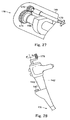
- the driven gear to be provided on the outer periphery of the rotating member 156 is a spur gear 171.
- a spur gear 172 as a drive gear engages the spur gear 171.
- the spur gear 172 as the drive gear is supported in the distal portion of the insertion portion 141.
- a distal end of a torque transmission wire 173, which is configured to transmit rotational torque, is connected to a shaft of the spur gear 172.
- the operator rotates the spur gear 172 as the drive gear and the spur gear 171 as the driven gear by twisting and rotating the torque transmission wire 173 from the proximal side.
- the rotating member 156 rotates together therewith.
- a rotating lever 175 is provided on the control section 142 of the introduction guide tube 170 so that the torque transmission wire 173 is rotated by operating the rotating lever 175.
- the direction of operation of the operating mechanism on the proximal side by the rotating lever 175 is substantially parallel to the axis of rotation of the rotating mechanism at the distal end of the insertion portion.
- the structure of the treatment tool rotating mechanism other than those described here may be substantially the same as the above-described embodiments.
- the treatment tool rotating mechanism can be used for changing the direction of rotation of the treatment tool 150. Since the driven gear is the spur gear 171 and the drive gear is the spur gear 172, and the spur gear 172 is rotated by the torque transmission wire 173, a mechanism to be built in the distal portion of the introduction guide tube 170 can be simplified.
- the treatment tool operating mechanism for moving the treatment tool in the fore-and-aft direction or for rotating the same is such that the treatment tool is built in the distal portion of the introduction guide tube in the aforementioned description, it is also possible to combine both configurations to obtain a form in which the treatment tool operating mechanism for moving the treatment tool in the fore-and-aft direction and rotating the same.
- the proximal portion of the treatment tool is twisted or moved in the fore-and-aft direction on the proximal side of the introduction guide tube.
- the insertion portion of the treatment tool introduced via the interior of the introduction guide tube is elongated and flexible, and the insertion portion of the treatment tool comes into contact with the inner wall of the introduction guide tube at many points and often snakes its way therein.
- the insertion portion of the treatment tool comes into a pressing contact with the inner wall of the introduction guide tube at the bending portion.
Description
- The present invention relates to an endoscope therapeutic device for performing treatment under observation via an endoscope by introducing a treatment tool through an introduction guide tube with a bending function into a body cavity, and an introduction guide tube thereof.
- An endoscope therapeutic device for performing treatment using a treatment tool under observation via an endoscope by introducing the treatment tool through an introduction guide tube into a body cavity is known in the related art. The introduction guide tube used in the endoscope therapeutic device of this type is referred also as a "channel tube". Recently, as an introduction guide tube of this type, an introduction guide tube with a bending function, in which a bending portion is provided in the vicinity of the distal end of the tube, and the bending portion is capable of being bent by a proximal control section is proposed (See
JP-A-2000-33071 -
US 6,066,090 discloses a two-branch endoscope including a first endoscope branch and a second endoscope branch. Each branch is separately steerable and the first endoscope branch may be used to view the distal end of the second endoscope branch. Each endoscope branch includes an illumination source, an image receiver and an operating channel. Each endoscope branch may also be independently adjusted to the range of angles of a selectable sweep of azimuth and may be steered to assume a small radius curl or may be steered in a large radius curl. -
US 6,071,233 discloses an endoscope having a main body and a channel tube provided on the exterior of the main body. The main body of the endoscope consists of an insert and a proximal control section. The insert is constituted of a distal end portion, a bendable portion, and a flexible tube portion arranged sequentially from the distal end side. An observation window is formed in the distal end face. The external channel tube is a flexible tube member thinner in diameter than the insert and therefore capable of bending relatively flexible. The channel tube is set longitudinally along the insert of the endoscope and in contact with the upper face portion thereof. A tube sheath of a basket-type foreign-body removing tool is inserted into the channel tube. - Patent Abstracts of Japan
JP 2000-033071 A claim 1 is based on this document. -
US 5,511,564 discloses a laparoscopic stretching instrument. Laparoscopy involves the piercing of the abdominal wall and the insertion of a tubular port member or laparoscopic cannula through the perforation. Spring loaded locking pins are provided on two shafts for cooperating with apertures in a sleeve to alternately lock the respective shaft in a retracted neutral position and an extended use position. - The object of the present invention is achieved by an endoscope therapeutic device according to
claim 1 with preferred embodiments discloses in the dependent claims. - An exemplary endoscope therapeutic device includes a plurality of introduction guide tubes for introducing treatment tools into a body cavity, wherein the plurality of introduction guide tubes are joined to each other at portions proximal to the bending portions thereof. In a case where there are a plurality of bending portions on the introduction guide tube, a joint portion is placed in a more proximal position than the distal-most bending portion.
- In this manner, the effects caused by the movement of a plurality of the introduction guide tubes are mutually invalidated at a joint portion as a fulcrum, so that the position of the introduction guide tube is relatively stabilized in the body cavity. Therefore, the operability is improved. Also, since the bending portions are located on the more distal side than the joint portion, good operability can be maintained even when they are joined.
- The form of joint may be such that a part of the insertion portion that is located on a more proximal side than the bending portion of the introduction guide tube is integrally joined with other introduction guide tubes. In this case, a stable connection is achieved. It is also possible to join the introduction guide tubes with a joint tool. In this case, since the introduction guide tubes can be replaced, it is applicable to various embodiments. It is also possible to provide a connecting function to an over tube through which the introduction guide tubes are inserted.
- When the joint tool is resiliently deformed to tighten the introduction guide tubes to be inserted, a stable joint is achieved.
- In addition to the introduction guide tubes, the positions of the endoscope, a suction tube, and the like in the body cavity are also stabilized by being joined as a matter of course. Further, an operating mechanism for operating the distal end of the treatment tool to be inserted therethrough may preferably be provided at the distal end of the introduction guide tube. Since the introduction guide tube is provided with a function to operate the treatment tool in addition to the function to receive the treatment tool inserted therethrough, operability is improved. Since the treating portion and an element moved by operation are located close to each other, a delicate operation can be performed.
- The operator can operate the treatment tools inserted through the guide tubes without releasing his/her hand from the guide tube by operating on the proximal side of the guide tube, and hence good operability is achieved. The operation of the treatment tool includes, for example, the fore-and-aft movement or the rotation of the treatment tool.
- These and other features, aspects, and advantages of the apparatus and methods of the present invention will become better understood with regard to the following description, appended claims, and accompanying drawings where:
-
Fig. 1A is a perspective view of an endoscope therapeutic device according to a first embodiment of the present invention; -
Fig. 1B is a perspective view of a distal portion of an endoscope for use with the endoscope therapeutic device ofFig. 1A ; -
Fig. 2 is a lateral cross-sectional view of a joint portion in the endoscope therapeutic device ofFig. 1A perpendicular to a longitudinal direction of an insertion portion as taken along line 2-2 thereof; -
Fig. 3 is an explanatory drawing showing the state of usage of the endoscope therapeutic device according to the first embodiment; -
Fig. 4 is a perspective view showing the joint in an enlarged manner in a state in which a treatment tool introduction guide tube unit is attached to the endoscope in the endoscope therapeutic device according to the first embodiment; -
Fig. 5 is a perspective view showing the joint for assembling the treatment tool introduction guide tube unit to the endoscope in the endoscope therapeutic device according to the first embodiment; -
Fig. 6 is a perspective view showing the introduction guide tube in the treatment tool introduction guide tube unit of the endoscope therapeutic device according to the first embodiment; -
Fig. 7 is a cross-sectional view of a distal end portion of the introduction guide tube in the treatment tool introduction guide tube unit of the endoscope therapeutic device according to the first embodiment; -
Fig. 8 is a partial perspective view of the endoscope therapeutic device according to a second exemplary embodiment not forming part of the present invention; -
Fig. 9 is a perspective view showing an over tube of the endoscope therapeutic device according to the second embodiment; -
Fig. 10 is a cross-sectional view of a fixed portion of the endoscope therapeutic device ofFig. 8 as taken along line 10-10 thereof; -
Fig. 11 is an explanatory drawing showing the state of usage of the endoscope therapeutic device according to the second embodiment; -
Fig. 12 is an explanatory drawing showing the joint method realized by a joint tool according to a third exemplary embodiment not forming part of the present invention; -
Fig. 13 is an explanatory drawing showing the state of usage of the endoscope therapeutic device according to the third embodiment; -
Fig. 14 is a perspective view showing a distal end of the endoscope therapeutic device according to a fourth exemplary embodiment not forming part of the present invention; -
Fig. 15 is a perspective view showing the distal end of the endoscope therapeutic device according to a fifth exemplary embodiment not forming part of the present invention; -
Fig. 16 is a perspective view showing a control section of the introduction guide tube in the endoscope therapeutic device according to a sixth exemplary embodiment not forming part of the present invention; -
Fig. 17 is a plan view of the control section of the introduction guide tube in the endoscope therapeutic device according to the sixth embodiment; -
Fig. 18A and Fig. 18B are vertical cross-sectional views of the distal end of the introduction guide tube in the endoscope therapeutic apparatus according to the sixth embodiment; -
Fig. 19A and Fig. 19B are perspective views showing the distal end of the introduction guide tube in the endoscope therapeutic device according to a seventh exemplary embodiment not forming part of the present invention; -
Fig. 20 is a perspective view showing the control section of the introduction guide tube in the endoscope therapeutic device according to an eighth exemplary embodiment not forming part of the present invention; -
Fig. 21 is a perspective view showing a treatment tool rotating mechanism built in the distal end of the introduction guide tube in the endoscope therapeutic device according to the eighth embodiment of the present invention; -
Fig. 22 is a vertical cross-sectional view of the treatment tool rotating mechanism built in the distal end of the introduction guide tube in the endoscope therapeutic device according to the eighth embodiment; -
Fig. 23 is a plan view showing a gear train of the treatment tool rotating mechanism built in the distal end of the introduction guide tube in the endoscope therapeutic device according to the eighth embodiment; -
Fig. 24 is a perspective view showing the gear train of the treatment rotating mechanism built in the distal end of the introduction guide tube in the endoscope therapeutic device according to the eighth embodiment; -
Fig. 25 is a perspective view of the distal end when the introduction guide tube of the endoscope therapeutic device according to the eighth embodiment is in use; -
Fig. 26 is a vertical cross-sectional view of the distal end of the introduction guide tube of the endoscope therapeutic device according to the eighth embodiment when in use; -
Fig. 27 is a perspective view showing the treatment tool rotating mechanism built in the distal end of the introduction guide tube in the endoscope therapeutic device according to a ninth exemplary embodiment not forming part of the present invention; and -
Fig. 28 is a side view of the control section of the introduction guide tube in the endoscope therapeutic device according to the ninth embodiment. - Embodiments of the invention will be described below with reference to the accompanying drawings.
- Referring now to
Fig. 1 to Fig. 7 , an endoscope therapeutic device according to a first embodiment of the present invention will be described.Fig. 1A is a perspective view of an endoscope therapeutic device according to the first embodiment of the present invention. A treatment tool introductionguide tube unit 1 is shown inFig. 1A. Fig. 1B shows aninsertion portion 3 of anendoscope 2. In the endoscope therapeutic device according to the first embodiment, the treatment tool introductionguide tube unit 1 is joined to theinsertion portion 3 of theendoscope 2 by the joint tool described above. - The treatment tool introduction
guide tube unit 1 includes a plurality of treatment toolintroduction guide tubes introduction guide tubes insertion portion 5 thereof by ajoint portion 6, and is fixed and joined integrally. Ajoint hood 26, which constitutes thejoint portion 6 is formed of a flexible material. A mode for joining the two treatment toolintroduction guide tubes joint hood 26 is shown inFig. 2 . It is also possible to form at least part of theinsertion portions 5 of the two treatment toolintroduction guide tubes joint hood 26 as described above. For example, at least thejoint portion 6 can be configured in such a manner. In this case as well, a fixed structure in which theinsertion portions 5 of a plurality of the treatment toolintroduction guide tubes -
Fig. 6 is a perspective view of the treatment toolintroduction guide tube 4a (4b). As shown inFig. 6 , theinsertion portions 5 of the treatment toolintroduction guide tubes distal portion 10 located at a distal end thereof, afirst bending portion 11 is located on the proximal side of thedistal portion 10, asecond bending portion 12 is located on the proximal side of thefirst bending portion 11, and aflexible portion 13 is provided behind thesecond bending portion 12. Aproximal control section 20 is provided at the proximal end of theinsertion portion 5 of each of the treatment toolintroduction guide tubes proximal control sections 20 each include agrip portion 21, aninsertion port 22 which communicates with a treatment tool guiding channel 14 (seeFig. 7 ), and a plurality of operating members for bending the bendingportions angle knobs first bending portion 11 in two directions and one angle handle 24 for operating thesecond bending portion 12 in a single (e.g., vertical) direction. -
Fig. 7 is a vertical cross-sectional view of theinsertion portion 5 of the treatment tool introduction guide tube in the treatment tool introduction guide tube unit. As shown inFig. 7 , aflexible tube 15 forming the treatmenttool guiding channel 14 is disposed over the entire length in theinsertion portion 5 of each of the treatment toolintroduction guide tubes tool guiding channel 14 opens toward the outside at the distal extremity of theinsertion portion 5 via achannel hole 16 at thedistal portion 10 and at the control section at the insertion port. - The
first bending portion 11 includes a plurality of bendingelements 17 joined so as to be capable of rotating freely to allow bending in the vertical and lateral directions, and is bent in the pulling direction of anoperating wire 18 by pulling a plurality of the operatingwires 18. Although the second bending portion 12 (seeFig. 6 ) also has the same configuration to be bent by means of a plurality of the bending pieces, thesecond bending portion 12 is configured so as to be bent only in the vertical direction. - As shown in
Fig. 1A , thesecond bending portion 12 is provided so as to extend or project from the distal end of thejoint portion 6. In other words, in the respective treatment toolintroduction guide tubes portions joint hood 26. In the first embodiment in this configuration, a fixing portion (fixing means) for fixing the portions of the treatment toolintroduction guide tubes portions joint hood 26 constitutes a therapeutic instrument joint tool for joining a plurality of the treatment toolintroduction guide tubes - Then, the distal end of the
joint hood 26 which supports both of the movable sections of the respective treatment toolintroduction guide tubes common fulcrum 27. Therefore, the movable sections including the bendingportions common fulcrum 27. Thefulcrum 27 is also a common fixed point for the movable sections of the respective treatment toolintroduction guide tubes - Subsequently, referring to
Fig. 1B , theendoscope 2 will be described.Fig. 1B is a perspective view of theinsertion portion 3 of theendoscope 2. As shown inFig. 1B , theinsertion portion 3 of theendoscope 2 includes adistal portion 31 located at a distal extremity thereof, a bendingportion 32 located on the proximal side of thedistal portion 31, and aflexible portion 33 located on the proximal side of the bendingportion 32. Theendoscope 2 has an observation function by the provision of an inspection window 34, anillumination window 35, and achannel port 36 at the distal end surface of thedistal portion 31. The bendingportion 32 is bent by a control section (not shown) provided at a proximal end of theinsertion portion 3. -
Fig. 3 is an explanatory drawing showing the state of usage of the endoscopetherapeutic device 1 including the treatment toolintroduction guide tubes endoscope 2 assembled together according to the first embodiment. As shown inFig. 3 , the treatment tool introductionguide tube unit 1 is joined to theinsertion portion 3 of theendoscope 2 by ajoint tool 40 in a state of being placed along theinsertion portion 3 of theendoscope 2. Thejoint tool 40 is disposed in the vicinity of the distal end of theflexible portion 33 averting the bendingportion 32 of theendoscope 2. Since the portion of the treatment tool introductionguide tube unit 1 in the vicinity of the distal end is joined by thejoint tool 40, the movable sections of the respective treatment toolintroduction guide tubes portions portion 32 of theendoscope 2, and are configured to be movable with respect to each other. - As shown in
Fig. 4 andFig. 5 , thejoint tool 40 includes aband member 43 having aninsertion hole 41 for allowing thejoint portion 6 of the treatment tool introductionguide tube unit 1 to be inserted therethrough and aninsertion hole 42 for allowing theinsertion portion 3 of theendoscope 2 to be inserted therethrough, and theband member 43 is capable of opening and closing so that one end can be opened about ahinge 44 on the other end. Aprojection 45 is formed on one of the edges at the openable end of theband member 43 and a correspondinghole 46 for receiving theprojection 45 for engagement is formed on the other edge. - Subsequently, a case of using the endoscope therapeutic device will be described. As shown in
Fig. 3 , the operator assembles the treatment tool introductionguide tube unit 1 to theinsertion portion 3 of theendoscope 2 and guides the same into a body cavity as one unit. When guiding the unit assembled into one piece into the body cavity as described above, it is also possible to guide it into the body cavity using a trocar or an over tube (not shown) as a guiding member as is known in the art. - Then, the operator introduces the various treatment tools (including a suction tool) into the body cavity via the respective treatment tool
introduction guide tubes guide tube unit 1, which are joined to theinsertion portion 3 of theendoscope 2, while observing the body cavity by theendoscope 2 to perform a required treatment. It is also possible to introduce another treatment tool through thechannel port 36 and corresponding channel provided on theendoscope 2 to perform a treatment simultaneously. -
Fig. 3 shows a state in whichtissue 47 is pulled upward. In this example of treatment, the operator pulls up thetissue 47 using graspingforceps 48 introduced through one of the treatment toolintroduction guide tubes 4a, holds thetissue 47 using the graspingforceps 49 introduced through the otherintroduction guide tube 4b, and moves the respective treatment tools in the opposite direction. In other words, the operator bends the bendingportions introduction guide tubes forceps tissue 47. - Here, since the movable sections of the respective treatment tool
introduction guide tubes forceps fulcrum 27, supporting forces exerted to the fulcrum 27 are mutually invalidated (canceled), and the movable sections of the respective treatment toolintroduction guide tubes fulcrum 27. Thefulcrum 27 is approximately considered as a fixed point. Therefore, a force to be exerted to the graspingforceps tissue 47 as is. Such behavior is not limited to the case of puling up thetissue 47, but may be the same in the surgical operation such as to expand thetissue 47. - In general, in case of using the single introduction guide tube or the flexible endoscope independently, the flexible portion of the insertion portion is suspended in a space of the body cavity by the reaction received from the grasping forceps so as to be capable of moving freely. Therefore, a force exerted to the tissue can become extremely small because the force generated by the reaction is absorbed in the flexible insertion portion.
- However, in the first embodiment, since the movable sections of the respective treatment tool
introduction guide tubes forceps common fulcrum 27, the supporting forces generated by the reaction and exerted to the fulcrum 27 are mutually invalidated at thefulcrum 27, whereby relatively stable support of the movable sections of the treatment toolintroduction guide tubes introduction guide tubes grip forceps introduction guide tubes endoscope 2. - In the first embodiment described above, the case in which the treatment tool introduction
guide tube unit 1 is used by being joined to theinsertion portion 3 of theendoscope 2 has been described. However, the same advantages can be achieved in the case in which the treatment tool introductionguide tube unit 1 having a plurality of the treatment tool introduction guide tubes joined to each other is used independently. However, when the treatment tool introductionguide tube unit 1 is used by being joined to theinsertion portion 3 of theendoscope 2, the positional relation with respect to theendoscope 2 is established during use, and hence the surgical situation can be observed easily, and the stable supporting balance is provided to the entire unit, whereby stability of operation is increased, thereby improving usability. - In the case in which the treatment tool is used via the channel provided in the
endoscope 2, the form of usage in which the supporting function is provided as described above is also conceivable as well as other various forms of usage. - Referring now to
Fig. 8 to Fig. 11 , the endoscope therapeutic device according to a second embodiment of the present invention will be described. The same parts to those in the embodiment described above will be represented by the same reference numerals in the description. -
Fig. 8 is a partial perspective view of the endoscope therapeutic device according to the second embodiment of the present invention. As shown inFig. 8 , the treatment tool introductionguide tube unit 1 according to the second embodiment is an assembly of the two treatment toolintroduction guide tubes tube 61 formed of flexible material. The treatment toolintroduction guide tubes -
Fig. 9 is a perspective view showing the overtube 61 of the endoscope therapeutic device according to the second embodiment, andFig. 10 is a lateral cross-sectional view of a fixed portion of the treatment tool introduction guide tube built in the overtube 61. As shown inFig. 9 , the overtube 61 is formed with twoinsertion holes introduction guide tubes Fig. 10 , although therespective insertion holes partitioning wall 63 for guiding the treatment toolintroduction guide tubes insertion holes - A fixing
screw 64 is screwed into a sidewall of one of theinsertion holes 62b, and the treatment toolintroduction guide tube 4b inserted through theinsertion hole 62b is tightened by thescrew 64, so that the treatment toolintroduction guide tube 4b can be fixed. The treatment toolintroduction guide tube 4a inserted through theother insertion hole 62a is tightened by resilient deformation of theover tube 61, which occurs when the treatment toolintroduction guide tube 4b is tightened by thescrew 64, and is fixed to theinsertion hole 62b thereby. - In other words, in the second embodiment in this configuration, the fixing portion (fixing means) for fixing the portions of the treatment tool
introduction guide tubes portions tube 61 itself constitutes the treatment equipment joint tool for joining a plurality of the treatment toolintroduction guide tubes - As shown in
Fig. 8 , when the two treatment toolintroduction guide tubes tube 61, thedistal portion 10 and the sections of the bendingportions over tube 61 and project forward (distally). Normally, the distal ends of theflexible portions 13 are also projected at least slightly when mounted. - Subsequently, the case where this endoscope therapeutic device is used will be described.
Fig. 11 is an explanatory drawing showing the state of usage of the endoscope therapeutic device. As shown inFig. 11 , the operator mounts the two treatment toolintroduction guide tubes tube 61 respectively to form a single unit, and guides the same into the body cavity using the guide means such as trocar. Here, since the treatment toolintroduction guide tubes over tube 61 are retained with the distal end of theover tube 61 as thefulcrum 27, the movement of the treatment toolintroduction guide tubes forceps introduction guide tubes introduction guide tubes fulcrum 27, and hence the force exerted to the graspingforceps tissue 47 without dissipation. - Alternatively, the operator can fix the portion in the vicinity of the boundary between the
first bending portion 11 and thesecond bending portion 12 onto the overtube 61 by means of thescrew 64 or the like with the sections of thesecond bending portions 12 of the respective treatment toolintroduction guide tubes tube 61 and with only thefirst bending portion 11 projected from the overtube 61. In this case, only thefirst bending portion 11 is bent about the portion in the vicinity of the boundary between thefirst bending portion 11 and thesecond bending portion 12 is set as a fulcrum. In other words, the present invention is not limited to the portion in the vicinity of the proximal end of the proximal-mostsecond bending portion 12, but may take a form in which the portion located at the midsection of the bending portion is fixed. - In the second embodiment, the
endoscope 2 is provided separately from the unit, and as shown inFig. 11 , theendoscope 2 can be guided in thebody cavity 65 along the overtube 61 of the unit for observing the state of treatment, or can guide a treatment tool such as a separateelectrosurgical knife 66.Fig. 11 shows a state of incising thetissue 47, which is pulled up by the graspingforceps electrosurgical knife 66 introduced through theendoscope 2. - Referring now to
Fig. 12 and Fig. 13 , the endoscope therapeutic device according to a third exemplary embodiment will be described. The same parts as in the embodiments described above are represented by the same reference numerals. - The third embodiment is configured in such a manner that the above-described two treatment tool
introduction guide tubes endoscope 2 are joined by ajoint tool 71. As shown inFig. 12 , thejoint tool 71 includes aresilient member 75 having ahole portion 72 for fitting theinsertion portion 5 of the treatment toolintroduction guide tube 4a, ahole portion 73 for fitting theinsertion portion 5 of the treatment toolintroduction guide tube 4b, and ahole portion 74 for fitting theinsertion portion 3 of theendoscope 2 disposed radially. Thehole portions joint tool 71 each are formed with aslit 76 for allowing the member to be put in or removed at the midsection thereof by deforming the portions of theresilient member 75 proximate to theslits 76 to insert the respective insertion portions of the treatment toolintroduction guide tubes endoscope 2. -
Fig. 13 shows the state of usage of the third embodiment. Theinsertion portion 5 of the treatment toolintroduction guide tube 4a, theinsertion portion 5 of the treatment toolintroduction guide tube 4b, and theinsertion portion 3 of theendoscope 2 are mounted by being fitted to thehole portions joint tool 71 corresponding thereto, respectively. Thejoint tool 71 is mounted and fixed to thedistal portion 31 of theendoscope 2. In order to fixedly retain theflexible portions 13 of the treatment toolintroduction guide tubes fulcrum 27 of the treatment toolintroduction guide tubes Fig. 13 , when the treatment toolintroduction guide tubes endoscope 2 are connected by thejoint tool 71, the treatment toolintroduction guide tubes insertion portion 3 of theendoscope 2. Consequently, the same usage as the second embodiment described above is enabled. Thejoint tool 71 may also be disposed at other positions of theendoscope 2 and/or treatment toolintroduction guide tubes - Subsequently, referring to
Fig. 14 , the endoscope therapeutic device according to a fourth exemplary embodiment will be described. The same parts as in the embodiments described above are represented by the same reference numerals in the description. - An over
tube 80 having a bending function is employed in the fourth embodiment. The distal portion of theover tube 80 includes a bendingportion 81, and the bendingportion 81 is bent by the control section (not shown) disposed on a proximal side of theover tube 80. The overtube 80 is formed with ahole 83 for receiving anintroduction guide tube 82 inserted therethrough, twoholes 85 for receiving tworespective suction tubes hole 86 for receiving theinsertion portion 3 of theendoscope 2 in a sectional manner. - Then, when the
introduction guide tube 82, thesuction tubes insertion portion 3 of theendoscope 2 are inserted through the correspondingholes over tube 80 respectively, these members are unitized. The overtube 80 includes a fixed portion in the vicinity of the distal portion thereof, so that the inserted tools can be supported so that the relative position between theover tube 80 and the inserted tools does not change in the radial direction. Theintroduction guide tube 82 and thesuction tubes tube 80 so as to be capable of moving in the fore-and-aft direction without wobbling in the radial direction. The movable sections of theintroduction guide tube 82 and thesuction tubes over tube 80 are formed with bendingportions 87 which are similar to that described above with regard to the treatment toolintroduction guide tubes portions 87 projecting from the distal end of theover tube 80 are supported by the overtube 80, and the portions of theover tube 80 in the vicinity of the distal end serves as a fulcrum of the movable sections projecting forward therefrom. - When using this unit, as shown in
Fig. 14 , the operator causes theintroduction guide tube 82, thesuction tubes insertion portion 3 of theendoscope 2 to project from the distal end of theover tube 80. Then, for example, the distal ends of the twosuction tubes tissue 47 to adsorb thetissue 47. The operator can also bend the bendingportion 87 of thesuction tubes over tubes 80 as needed and pull thetissue 47 upward. The operator can also expand thetissue 47 by bending the bendingportions 87 of thesuction tubes over tube 80, as needed in the directions away from each other. - In the usage thereof, since the movable sections of the
respective suction tubes suction tubes suction tubes over tube 80 as the fulcrum. The treatment tools may be projected from theintroduction guide tube 82 for treatment. - The
introduction guide tube 82 may be used as the suction tube. Alternatively, thesuction tubes - Referring now to
Fig. 15 , the endoscope therapeutic device according to a fifth exemplary embodiment be described. The same parts as in the embodiments described above are represented by the same reference numerals for description. - In the fifth embodiment, an over
tube 90 is employed. The overtube 90 is formed integrally with a plurality ofmanipulators over tube 90. One of themanipulators 91a is provided with adistal operating section 92 having flexibility, which is similar to the movement of the fingers of a human being, and theother manipulator 91b is provided with a bendingportion 93 with the bending function having flexibility which is similar to the movement of the wrist or elbow of a human being. Therespective manipulators manipulators - The over
tube 90 is formed with aninsertion channel 95 to which theinsertion portion 3 of theendoscope 2 is introduced. Theendoscope 2 used here has an extrathin insertion portion 3 having only an observing function. - When using the endoscope therapeutic device, as shown in
Fig. 15 , the operator performs treatment by gripping the treatment tool or by nipping the tissue directly using the left andright manipulators - The left and
right manipulators over tube 90, and fixedly and integrally supported. Accordingly, this supporting portion serves as the fulcrum of themanipulators respective manipulators respective manipulators respective manipulators over tube 90 as the fulcrum. - Referring now to
Fig. 16 to Fig. 18 , another therapeutic device in which the introduction guide tube as described above is modified will be described as a sixth exemplary embodiment . As shown inFig. 16 and Fig. 17 , anintroduction guide tube 100 in this therapeutic device includes aflexible insertion portion 101 and acontrol section 102, and thecontrol section 102 includes agrip portion 103, a plurality ofangle knobs 105 for bending the bending portion of theinsertion portion 101, aninsertion port 107 that communicates with a channel of theinsertion portion 101, and a treatmenttool operating lever 109 for operating a treatment tool operating mechanism, described later. Theangle knob 105 is provided with abrake knob 105a for locking the operating position thereof. The brake knob may be provided also on the treatmenttool operating lever 109. -
Fig. 18A and Fig. 18B are vertical cross-sectional views of a distal end of the introduction guide tube in the endoscope therapeutic device according to the sixth embodiment. As shown inFig. 18A and Fig. 18B , aninsertion portion 110a of atreatment tool 110, such as grasping forceps, is inserted from theinsertion port 107 of thecontrol section 102 of theintroduction guide tube 100 through achannel 106, so as to be projected into the body cavity from anopening 106a at the distal end of thechannel 106. - A treatment
tool operating mechanism 108 is built in the distal portion of theinsertion portion 101. The treatmenttool operating mechanism 108 here includes a ring-shapedmovable element 115 which allows insertion of theinsertion portion 110a of thetreatment tool 110 in the distal portion of theinsertion portion 101 so as to be capable of linear movement in the fore-and-aft axial direction. The distal end of anoperating wire 116 inserted through theinsertion portion 110 is connected to themovable element 115. Accordingly, a movement control mechanism in which theoperating wire 116 is moved in the fore-and-aft axial direction when the treatmenttool operating lever 109 of the above-describedcontrol section 102 is operated, whereby themovable element 115 of the treatmenttool operating mechanism 108 is moved in the fore-and-aft direction and thedistal end 110a of thetreatment tool 110 is moved in the fore-and-aft direction, is configured. Themovable element 115 constitutes a mechanism for selectively engaging and disengaginggrip arms 117 as engaging members that engage part of theinsertion portion 110a of thetreatment tool 110 by theoperating wire 116, which is operated on the proximal side. - As shown in
Fig. 18A and Fig. 18B , a plurality of thegrip arms 117 as engaging members that engage part of theinsertion portion 110a of thetreatment tool 110 project forward from themovable element 115. The distal portions of therespective grip arms 117 are resiliently biased so as to open outwardly in the free state shown inFig. 18B . Eachgrip arm 117 is integrally formed with a holdingportion 118 at the distal end thereof. A tighteningmember 121 is attached on the outside of eachgrip arm 117, and the tighteningmember 121 is capable of sliding freely in the range between themovable element 115 and the holdingportion 118. Theinsertion portion 101 is formed with aguide rail 122 in the distal portion so as to guide the tighteningmember 121 linearly in the fore-and-aft direction. Positioning stoppers (stepped portions) 123a, 123b formed of walls extending vertically upward are formed at the front end and the rear end of theguide rail 122, so that front and rear terminal positions of movement of the tighteningmember 121 are defined respectively. - The tightening
member 121 includes a slidingportion 124 to be guided by theguide rail 122 and afastening ring portion 125 that slides on the outer periphery of thegrip arm 117. As shown inFig. 18A , when the tighteningmember 121 is retracted, therespective grip arms 117 are tightened by the tighteningmember 121, and the holdingportions 118 of therespective grip arms 117 are pressed against the outer periphery of theinsertion portion 110a of thetreatment member 110 to grip thetreatment tool 110 by themovable element 115. - By moving the
movable element 115 by theoperating wire 116 in the fore-and-aft direction in the state in which the treatment tool is constrained as shown inFig. 18A , thetreatment tool 110 can be moved in the fore-and-aft direction together with themovable element 115. In this manner, complicated operation such as to operate with the hand unlinked from the control section of theintroduction guide tube 100 or the endoscope as in a case where the operator grips the distal end of thetreatment tool 110 directly and pulls and pushes the proximal end of thetreatment tool 110 by hand to move the distal portion in the fore-and-aft direction is not necessary, and the fore-and-aft movement of thetreatment tool 110 can be performed easily without releasing the hand from the control section. - When the tightening
member 121 is moved forward as shown inFig. 18B , the distal portions of therespective grip arms 117 open and release thetreatment tool 110. In other words, the holdingportions 118 of therespective grip arms 117 retract from theinsertion portion 110a of thetreatment tool 110 and release thetreatment tool 110 from the gripped state shown inFig. 18A . Therefore, thetreatment tool 110 can be moved in the fore-and-aft direction or in the rotational direction independently of theintroduction guide tube 100, whereby the operability of thetreatment tool 110 is improved. - The
introduction guide tube 100 is used as the introduction guide tube in the device in the therapeutic system described above, and can be used for introduction of various treatment tools. It can also be applied to an unit form in which a plurality of theintroduction guide tubes 100 are joined so that the supporting forces exerted to the movable sections of a plurality of theintroduction guide tubes 100 are mutually invalidated at the common fulcrum. The general existing introduction guide tube is simply used for inserting the treatment tool therethrough. However, with theintroduction guide tube 100 disclosed here, thetreatment tool 110 can be rotated or moved in the fore-and-aft direction positively, and hence the reliable operation of thetreatment tool 110 is achieved. Theintroduction guide tube 100 guarantees beneficial effects also when using theintroduction guide tube 100 independently and separately from theendoscope 2. - Subsequently, referring to
Fig. 19A and Fig. 19B , a modification of the above-described introduction guide tube will be described as a seventh exemplary embodiment . Anintroduction guide tube 130 of this type differs from the above-describedintroduction guide tube 100 in that there is provided a treatment tool advancing-retracting mechanism. In other words, the treatment tool advancing-retracting mechanism supports aseparate extremity member 132 at thedistal portion 131 of theintroduction guide tube 130 via a plurality ofpush rods 133 so as to be capable of moving in the fore-and-aft direction. Thepush rods 133 are moved in the fore-and-aft direction by operating the treatmenttool operating lever 109 provided on thecontrol section 102 of theintroduction guide tube 130, so that theextremity member 132 is moved in the fore-and-aft direction. -
Fig. 19A shows a state in which theextremity member 132 is waiting at a normal position which is retracted backward, andFig. 19B shows a state in which theextremity member 132 is moved forward. - As shown in
Fig. 19A and Fig. 19B , a ring-shapedresilient member 135 as the resilient member is disposed at the peripheral edge of the distal end opening of the channel formed on theextremity member 132. The ring-shapedresilient member 135 is used for gripping the insertion portion of thetreatment tool 110 projected from the distal end opening of the channel by tightening the same with a resilient force. Thetreatment tool 110 is retained by the resiliently tightening force of the ring-shapedresilient member 135 and hence follows the movement of theextremity member 132. However, the force that retainstreatment tool 110 is such that when theinsertion portion 110a of thetreatment tool 110 is pushed and pulled from the proximal side, only thetreatment tool 110 can move against the retaining force of the ring-shapedresilient member 135. It is also possible to retain thetreatment tool 110 with a force of a strength that cannot move thetreatment tool 110. - The above-described
introduction guide tube 130 can also be used as the above-described introduction guide tube and as a member for introducing the treatment tool as a matter of course, and it can also be applied to a unit form in which a plurality of theintroduction guide tubes 130 are joined so that the supporting forces exerted to the movable sections of a plurality of theintroduction guide tubes 130 are mutually invalidated at the common fulcrum. - Referring now to
Fig. 20 to Fig. 26 , another modification of the aforementioned introduction guide tube will be described as an eight exemplary embodiment . As shown inFig. 20 , theintroduction guide tube 140 includes aflexible insertion portion 141 and acontrol section 142. Thecontrol section 142 includes agrip portion 143, a plurality ofangle knobs 145 for bending a bending portion 144 (seeFig. 21 ) of theinsertion portion 141, aninsertion port 147 in communication with a channel 146 (seeFig. 22 ) of theinsertion portion 141, a treatmenttool rotating knob 149 for operating a treatment toolrotating mechanism 148 described later. Theangle knob 145 and the treatmenttool rotating lever 149 are provided withbrake knobs control section 142 is provided with anoperating button 137 for performing operations such as suction or air supply using thechannel 146. - As shown in
Fig. 25 and Fig. 26 , by inserting aninsertion portion 150a of atreatment tool 150 such as the grip forceps from theinsertion port 147 of thecontrol section 142 of theintroduction guide tube 140 through thechannel 146, thetreatment tool 150 is projected from a distal end opening of thechannel 146 into the body cavity. - The treatment tool
rotating mechanism 148 is assembled in the distal portion of theinsertion portion 141, and is configured as shown inFig. 21 to Fig. 26 . In other words, a cylindrical connectingmouth ring 153, to which the distal end of atube 152 defining thechannel 146 is connected, is provided in adistal portion 151 of theinsertion portion 141 of theintroduction guide tube 140, and the connectingmouth ring 153 is fixed to a supportingmember 154 fixed to thedistal portion 151. As shown inFig. 22 , a cylindrical rotatingmember 156 is disposed along the connectingmouth ring 153 and adistal wall 155 of thedistal portion 151, and the rotatingmember 156 is rotatably supported about an elongated shaft of thechannel 146 or a shaft extending in parallel with the elongated shaft. The rotatingmember 156 opens at the distal surface of thedistal portion 151 of theintroduction guide tube 140 and forms adistal end opening 146a of thechannel 146. - As shown in
Fig. 22 , abevel gear 157 as a driven gear is coaxially formed on the outer periphery of the rotatingmember 156. Abevel gear 158 as a drive gear engages thebevel gear 157. The shaft center of thebevel gear 158 is disposed orthogonally to the shaft center of thebevel gear 157 as the driven gear. Thebevel gear 158 as the drive gear is rotatably supported in the distal portion of theinsertion portion 141. Apinion gear 159 is coaxially and integrally formed with thebevel gear 158. As shown inFig. 23 , a pair ofracks pinion gear 159 so as to engage therewith. Therespective racks insertion portion 141 of theintroduction guide tube 140. - Distal ends of
operating wires respective racks operating wires racks pinion gear 159 rotates. - The
operating wires tool rotating knob 149 provided on thecontrol section 142 to move theracks - Then, by the movement of the
racks pinion gear 159 rotates together with thebevel gear 158, and thebevel gear 158 rotates thebevel gear 157 as the driven gear. When thebevel gear 157 as the driven gear rotates, the rotatingmember 156 rotates together. - On the other hand, as shown in
Fig. 22 andFig. 25 , aresilient member 165 formed of rubber or the like is provided at the peripheral edge of the distal end of the rotatingmember 156. Theresilient member 165 is exposed outward from thedistal portion 151 of theinsertion portion 141 of theintroduction guide tube 140. Theresilient member 165 serves as anchoring member which abuts against the distal end of the treatment tool inserted through thechannel 146, and anchors itself with respect to the distal end of the treatment tool by a frictional force against the treatment tool or deformation thereof, so as to cause the treatment tool to rotate with the rotatingmember 156. The treatment tool inserted through theintroduction guide tube 140 can be rotated by the treatment toolrotating mechanism 148. - When the
treatment tool 150 such as the grip forceps is inserted through theintroduction guide tube 140 for use, as shown inFig. 25 and Fig. 26 , the operator inserts aninsertion portion 150a of thetreatment tool 150 through thechannel 146 and allows adistal grasp member 150b of thetreatment tool 150 to project from the distal end of theintroduction guide tube 140. - Then, the operator opens the
distal grasp member 150b by operating alink mechanism 168 for operating an openable andclosable link mechanism 168, causes thedistal grasp member 150b to retract slightly in the opened state, and presses the member of thelink mechanism 168 against theresilient member 165 for anchoring. In other words, thedistal grasp member 150b of thetreatment tool 150 is joined with the rotatingmember 156 by a frictional force or an engaging force between theresilient member 165 and thelink mechanism 168, so as to rotate with the rotatingmember 156. - When changing the direction of the
treatment tool 150 by rotating the same, thedistal grasp member 150b of thetreatment tool 150 can be rotated with the rotatingmember 156. In other words, since thedistal grasp member 150b of thetreatment tool 150 is rotated directly, accurate relation with respect to the amount of rotation can be maintained, and thedistal grasp member 150b of thetreatment tool 150 can be rotated quickly. It is also possible to twist theelongated insertion portion 150a of thetreatment tool 150 from the proximal side to assist the rotation of thedistal grasp member 150b of thetreatment tool 150. - Referring now to
Fig. 27 and Fig. 28 , still another modification of the introduction guide tube provided with the treatment tool rotating mechanism as described above will be described as a ninth embodiment of the invention. - As shown in
Fig. 27 , in the treatment tool rotating mechanism of anintroduction guide tube 170, the driven gear to be provided on the outer periphery of the rotatingmember 156 is aspur gear 171. Aspur gear 172 as a drive gear engages thespur gear 171. Thespur gear 172 as the drive gear is supported in the distal portion of theinsertion portion 141. A distal end of atorque transmission wire 173, which is configured to transmit rotational torque, is connected to a shaft of thespur gear 172. - Then, the operator rotates the
spur gear 172 as the drive gear and thespur gear 171 as the driven gear by twisting and rotating thetorque transmission wire 173 from the proximal side. When thespur gear 171 rotates, the rotatingmember 156 rotates together therewith. - As shown in
Fig. 28 , arotating lever 175 is provided on thecontrol section 142 of theintroduction guide tube 170 so that thetorque transmission wire 173 is rotated by operating therotating lever 175. The direction of operation of the operating mechanism on the proximal side by therotating lever 175 is substantially parallel to the axis of rotation of the rotating mechanism at the distal end of the insertion portion. - The structure of the treatment tool rotating mechanism other than those described here may be substantially the same as the above-described embodiments.
- In this case as well, as in the above-described embodiments, the treatment tool rotating mechanism can be used for changing the direction of rotation of the
treatment tool 150. Since the driven gear is thespur gear 171 and the drive gear is thespur gear 172, and thespur gear 172 is rotated by thetorque transmission wire 173, a mechanism to be built in the distal portion of theintroduction guide tube 170 can be simplified. - Although the treatment tool operating mechanism for moving the treatment tool in the fore-and-aft direction or for rotating the same is such that the treatment tool is built in the distal portion of the introduction guide tube in the aforementioned description, it is also possible to combine both configurations to obtain a form in which the treatment tool operating mechanism for moving the treatment tool in the fore-and-aft direction and rotating the same.
- As described above, in the introduction guide tube in a form including the treatment tool operating mechanism which moves the treatment tool in the fore-and-aft direction or/and rotating the same, the following problems can be solved.
- In other words, when the direction or the position of the distal portion of the treatment tool introduced into the body cavity via the flexible introduction guide tube is changed as in the related art, the proximal portion of the treatment tool is twisted or moved in the fore-and-aft direction on the proximal side of the introduction guide tube.
- However, the insertion portion of the treatment tool introduced via the interior of the introduction guide tube is elongated and flexible, and the insertion portion of the treatment tool comes into contact with the inner wall of the introduction guide tube at many points and often snakes its way therein. In particular, when the bending portion of the introduction guide tube is bent, the insertion portion of the treatment tool comes into a pressing contact with the inner wall of the introduction guide tube at the bending portion.
- Under such a circumstance, even when the operator pushes and pulls the insertion portion of the treatment tool positioned in the introduction guide tube from the proximal side, or adds the rotating operation, the operating force is apt to be absorbed in route by snaking or twisting of the insertion portion of the treatment tool, and hence the operating force from the proximal side is hardly transmitted to the distal portion of the treatment tool.
- However, as described above, in a form in which the operating mechanism for moving the treatment tool in the fore-and-aft direction or the operating mechanism for rotating the treatment tool is built in the distal portion of the introduction guide tube, such disadvantages can be eliminated, and quick operation is enabled while maintaining the accurate relation with respect to the operating amount. Also, a complicated operation such as to operate with an operator's hand released from the control section of the introduction guide tube or the endoscope as in a case where the operator pushes or pulls the proximal portion of the treatment tool by hand is not necessary, and hence the operation of the treatment tool in the fore-and-aft direction can be performed easily without the operator removing his/her hand from the control section.
- While there has been shown and described what is considered to be preferred embodiments of the invention, it will, of course, be understood that various modifications and changes in form or detail could readily be made without departing from the scope of the claims. It is therefore intended that the invention be not limited to the exact forms described and illustrated, but should be constructed to cover all modifications that may fall within the scope of the appended claims.
Claims (4)
- An endoscope therapeutic device for introducing a treatment tool into a body cavity and performing treatment by the treatment tool under observation by an endoscope, the endoscope therapeutic device comprising:an endoscope (2);a plurality of introduction guide tubes (4a, 4b) for introducing the treatment tool into a body cavity, wherein each of the plurality of introduction guide tubes (4a, 4b) comprises an insertion portion (5), one or more bending portions (11, 12) provided at a distal side of the insertion portion (5) and being bendable by a bending operation, and a soft portion (13) provided proximally of the one or more bending portions (11, 12), anda mutual joint (6, 26) for joining at least two of the plurality of introduction guide tubes (4a, 4b) disposed at a position proximal to the distal-most bending portions (11, 12) of each of the at least two introducing guide tubes (4a, 4b),wherein the plurality of the introduction guide tubes (4a, 4b) are joined to the endoscope (2) at a position proximal to the position of the mutual joint (6, 26),characterized in that the mutual joint (6, 26) comprises fixing means that fixes at least two of the plurality of introduction tubes (4a, 4b) at proximal ends of the bending portions (11, 12) of the respective plurality of introduction tubes (4a, 4b) and that fixes the proximal ends of the bending portions (11, 12) to each other.
- The endoscope therapeutic device according to Claim 1, wherein the mutual joint (6, 26) of the at least two introduction guide tubes (4a, 4b) is achieved by a configuration in which at least part of the respective insertion portions of the at least two introduction guide tubes (4a, 4b) are integrally joined .
- The endoscope therapeutic device according to Claim 1, further comprising a joint tool (40) configured to join an insertion portion (3) of the endoscope (2) to the plurality of guide tubes (4a, 4b).
- The endoscope therapeutic device according to Claim 1, wherein at least one of the plurality of introduction guide tubes (4a, 4b) is provided at the distal portion thereof with an operating mechanism (108) for retaining a distal portion of a treatment tool inserted through the introduction guide tube (4a, 4b) and for moving the treatment tool.
Priority Applications (1)
| Application Number | Priority Date | Filing Date | Title |
|---|---|---|---|
| EP08014776A EP1985246B1 (en) | 2004-04-13 | 2005-04-08 | Endoscope therapeutic device |
Applications Claiming Priority (2)
| Application Number | Priority Date | Filing Date | Title |
|---|---|---|---|
| JP2004118182A JP2005296412A (en) | 2004-04-13 | 2004-04-13 | Endoscopic treatment apparatus |
| JP2004118182 | 2004-04-13 |
Related Child Applications (2)
| Application Number | Title | Priority Date | Filing Date |
|---|---|---|---|
| EP08014776A Division EP1985246B1 (en) | 2004-04-13 | 2005-04-08 | Endoscope therapeutic device |
| EP08014776.2 Division-Into | 2008-08-20 |
Publications (3)
| Publication Number | Publication Date |
|---|---|
| EP1586275A2 EP1586275A2 (en) | 2005-10-19 |
| EP1586275A3 EP1586275A3 (en) | 2005-12-07 |
| EP1586275B1 true EP1586275B1 (en) | 2013-05-29 |
Family
ID=34934933
Family Applications (2)
| Application Number | Title | Priority Date | Filing Date |
|---|---|---|---|
| EP08014776A Expired - Fee Related EP1985246B1 (en) | 2004-04-13 | 2005-04-08 | Endoscope therapeutic device |
| EP05007799.9A Expired - Fee Related EP1586275B1 (en) | 2004-04-13 | 2005-04-08 | Endoscope therapeutic device |
Family Applications Before (1)
| Application Number | Title | Priority Date | Filing Date |
|---|---|---|---|
| EP08014776A Expired - Fee Related EP1985246B1 (en) | 2004-04-13 | 2005-04-08 | Endoscope therapeutic device |
Country Status (3)
| Country | Link |
|---|---|
| US (2) | US20050228224A1 (en) |
| EP (2) | EP1985246B1 (en) |
| JP (1) | JP2005296412A (en) |
Cited By (72)
| Publication number | Priority date | Publication date | Assignee | Title |
|---|---|---|---|---|
| US8518024B2 (en) | 2006-04-24 | 2013-08-27 | Transenterix, Inc. | System and method for multi-instrument surgical access using a single access port |
| US8702620B2 (en) | 2008-11-03 | 2014-04-22 | G.I. View Ltd. | Remote pressure sensing system and method thereof |
| US9066747B2 (en) | 2007-11-30 | 2015-06-30 | Ethicon Endo-Surgery, Inc. | Ultrasonic surgical instrument blades |
| US9095367B2 (en) | 2012-10-22 | 2015-08-04 | Ethicon Endo-Surgery, Inc. | Flexible harmonic waveguides/blades for surgical instruments |
| US9198714B2 (en) | 2012-06-29 | 2015-12-01 | Ethicon Endo-Surgery, Inc. | Haptic feedback devices for surgical robot |
| US9220527B2 (en) | 2007-07-27 | 2015-12-29 | Ethicon Endo-Surgery, Llc | Surgical instruments |
| US9226766B2 (en) | 2012-04-09 | 2016-01-05 | Ethicon Endo-Surgery, Inc. | Serial communication protocol for medical device |
| US9226767B2 (en) | 2012-06-29 | 2016-01-05 | Ethicon Endo-Surgery, Inc. | Closed feedback control for electrosurgical device |
| US9232979B2 (en) | 2012-02-10 | 2016-01-12 | Ethicon Endo-Surgery, Inc. | Robotically controlled surgical instrument |
| US9237921B2 (en) | 2012-04-09 | 2016-01-19 | Ethicon Endo-Surgery, Inc. | Devices and techniques for cutting and coagulating tissue |
| US9241731B2 (en) | 2012-04-09 | 2016-01-26 | Ethicon Endo-Surgery, Inc. | Rotatable electrical connection for ultrasonic surgical instruments |
| US9241728B2 (en) | 2013-03-15 | 2016-01-26 | Ethicon Endo-Surgery, Inc. | Surgical instrument with multiple clamping mechanisms |
| US9283045B2 (en) | 2012-06-29 | 2016-03-15 | Ethicon Endo-Surgery, Llc | Surgical instruments with fluid management system |
| US9326788B2 (en) | 2012-06-29 | 2016-05-03 | Ethicon Endo-Surgery, Llc | Lockout mechanism for use with robotic electrosurgical device |
| US9351754B2 (en) | 2012-06-29 | 2016-05-31 | Ethicon Endo-Surgery, Llc | Ultrasonic surgical instruments with distally positioned jaw assemblies |
| US9393037B2 (en) | 2012-06-29 | 2016-07-19 | Ethicon Endo-Surgery, Llc | Surgical instruments with articulating shafts |
| US9408622B2 (en) | 2012-06-29 | 2016-08-09 | Ethicon Endo-Surgery, Llc | Surgical instruments with articulating shafts |
| US9414853B2 (en) | 2007-07-27 | 2016-08-16 | Ethicon Endo-Surgery, Llc | Ultrasonic end effectors with increased active length |
| US9427249B2 (en) | 2010-02-11 | 2016-08-30 | Ethicon Endo-Surgery, Llc | Rotatable cutting implements with friction reducing material for ultrasonic surgical instruments |
| US9439668B2 (en) | 2012-04-09 | 2016-09-13 | Ethicon Endo-Surgery, Llc | Switch arrangements for ultrasonic surgical instruments |
| US9439669B2 (en) | 2007-07-31 | 2016-09-13 | Ethicon Endo-Surgery, Llc | Ultrasonic surgical instruments |
| US9445832B2 (en) | 2007-07-31 | 2016-09-20 | Ethicon Endo-Surgery, Llc | Surgical instruments |
| US9504483B2 (en) | 2007-03-22 | 2016-11-29 | Ethicon Endo-Surgery, Llc | Surgical instruments |
| US9504855B2 (en) | 2008-08-06 | 2016-11-29 | Ethicon Surgery, LLC | Devices and techniques for cutting and coagulating tissue |
| US9510850B2 (en) | 2010-02-11 | 2016-12-06 | Ethicon Endo-Surgery, Llc | Ultrasonic surgical instruments |
| US9623237B2 (en) | 2009-10-09 | 2017-04-18 | Ethicon Endo-Surgery, Llc | Surgical generator for ultrasonic and electrosurgical devices |
| US9636135B2 (en) | 2007-07-27 | 2017-05-02 | Ethicon Endo-Surgery, Llc | Ultrasonic surgical instruments |
| US9649126B2 (en) | 2010-02-11 | 2017-05-16 | Ethicon Endo-Surgery, Llc | Seal arrangements for ultrasonically powered surgical instruments |
| US9700339B2 (en) | 2009-05-20 | 2017-07-11 | Ethicon Endo-Surgery, Inc. | Coupling arrangements and methods for attaching tools to ultrasonic surgical instruments |
| US9707027B2 (en) | 2010-05-21 | 2017-07-18 | Ethicon Endo-Surgery, Llc | Medical device |
| US9724118B2 (en) | 2012-04-09 | 2017-08-08 | Ethicon Endo-Surgery, Llc | Techniques for cutting and coagulating tissue for ultrasonic surgical instruments |
| US9764164B2 (en) | 2009-07-15 | 2017-09-19 | Ethicon Llc | Ultrasonic surgical instruments |
| US9801648B2 (en) | 2007-03-22 | 2017-10-31 | Ethicon Llc | Surgical instruments |
| US9820768B2 (en) | 2012-06-29 | 2017-11-21 | Ethicon Llc | Ultrasonic surgical instruments with control mechanisms |
| US9848901B2 (en) | 2010-02-11 | 2017-12-26 | Ethicon Llc | Dual purpose surgical instrument for cutting and coagulating tissue |
| US9848902B2 (en) | 2007-10-05 | 2017-12-26 | Ethicon Llc | Ergonomic surgical instruments |
| US9883884B2 (en) | 2007-03-22 | 2018-02-06 | Ethicon Llc | Ultrasonic surgical instruments |
| US9962182B2 (en) | 2010-02-11 | 2018-05-08 | Ethicon Llc | Ultrasonic surgical instruments with moving cutting implement |
| US10010339B2 (en) | 2007-11-30 | 2018-07-03 | Ethicon Llc | Ultrasonic surgical blades |
| US10034704B2 (en) | 2015-06-30 | 2018-07-31 | Ethicon Llc | Surgical instrument with user adaptable algorithms |
| US10034684B2 (en) | 2015-06-15 | 2018-07-31 | Ethicon Llc | Apparatus and method for dissecting and coagulating tissue |
| US10154852B2 (en) | 2015-07-01 | 2018-12-18 | Ethicon Llc | Ultrasonic surgical blade with improved cutting and coagulation features |
| US10179022B2 (en) | 2015-12-30 | 2019-01-15 | Ethicon Llc | Jaw position impedance limiter for electrosurgical instrument |
| US10194973B2 (en) | 2015-09-30 | 2019-02-05 | Ethicon Llc | Generator for digitally generating electrical signal waveforms for electrosurgical and ultrasonic surgical instruments |
| US10201382B2 (en) | 2009-10-09 | 2019-02-12 | Ethicon Llc | Surgical generator for ultrasonic and electrosurgical devices |
| US10201365B2 (en) | 2012-10-22 | 2019-02-12 | Ethicon Llc | Surgeon feedback sensing and display methods |
| US10226273B2 (en) | 2013-03-14 | 2019-03-12 | Ethicon Llc | Mechanical fasteners for use with surgical energy devices |
| US10245064B2 (en) | 2016-07-12 | 2019-04-02 | Ethicon Llc | Ultrasonic surgical instrument with piezoelectric central lumen transducer |
| US10251664B2 (en) | 2016-01-15 | 2019-04-09 | Ethicon Llc | Modular battery powered handheld surgical instrument with multi-function motor via shifting gear assembly |
| US10278721B2 (en) | 2010-07-22 | 2019-05-07 | Ethicon Llc | Electrosurgical instrument with separate closure and cutting members |
| USD847990S1 (en) | 2016-08-16 | 2019-05-07 | Ethicon Llc | Surgical instrument |
| US10285723B2 (en) | 2016-08-09 | 2019-05-14 | Ethicon Llc | Ultrasonic surgical blade with improved heel portion |
| US10285724B2 (en) | 2014-07-31 | 2019-05-14 | Ethicon Llc | Actuation mechanisms and load adjustment assemblies for surgical instruments |
| US10321950B2 (en) | 2015-03-17 | 2019-06-18 | Ethicon Llc | Managing tissue treatment |
| US10485607B2 (en) | 2016-04-29 | 2019-11-26 | Ethicon Llc | Jaw structure with distal closure for electrosurgical instruments |
| US10524854B2 (en) | 2010-07-23 | 2020-01-07 | Ethicon Llc | Surgical instrument |
| US10537352B2 (en) | 2004-10-08 | 2020-01-21 | Ethicon Llc | Tissue pads for use with surgical instruments |
| US10555769B2 (en) | 2016-02-22 | 2020-02-11 | Ethicon Llc | Flexible circuits for electrosurgical instrument |
| US10575892B2 (en) | 2015-12-31 | 2020-03-03 | Ethicon Llc | Adapter for electrical surgical instruments |
| US10595930B2 (en) | 2015-10-16 | 2020-03-24 | Ethicon Llc | Electrode wiping surgical device |
| US10595929B2 (en) | 2015-03-24 | 2020-03-24 | Ethicon Llc | Surgical instruments with firing system overload protection mechanisms |
| US10639092B2 (en) | 2014-12-08 | 2020-05-05 | Ethicon Llc | Electrode configurations for surgical instruments |
| US10646269B2 (en) | 2016-04-29 | 2020-05-12 | Ethicon Llc | Non-linear jaw gap for electrosurgical instruments |
| USRE47996E1 (en) | 2009-10-09 | 2020-05-19 | Ethicon Llc | Surgical generator for ultrasonic and electrosurgical devices |
| US10702329B2 (en) | 2016-04-29 | 2020-07-07 | Ethicon Llc | Jaw structure with distal post for electrosurgical instruments |
| US10842522B2 (en) | 2016-07-15 | 2020-11-24 | Ethicon Llc | Ultrasonic surgical instruments having offset blades |
| US10881449B2 (en) | 2012-09-28 | 2021-01-05 | Ethicon Llc | Multi-function bi-polar forceps |
| US10893883B2 (en) | 2016-07-13 | 2021-01-19 | Ethicon Llc | Ultrasonic assembly for use with ultrasonic surgical instruments |
| US11020140B2 (en) | 2015-06-17 | 2021-06-01 | Cilag Gmbh International | Ultrasonic surgical blade for use with ultrasonic surgical instruments |
| US11058447B2 (en) | 2007-07-31 | 2021-07-13 | Cilag Gmbh International | Temperature controlled ultrasonic surgical instruments |
| US11266430B2 (en) | 2016-11-29 | 2022-03-08 | Cilag Gmbh International | End effector control and calibration |
| US11324527B2 (en) | 2012-11-15 | 2022-05-10 | Cilag Gmbh International | Ultrasonic and electrosurgical devices |
Families Citing this family (732)
| Publication number | Priority date | Publication date | Assignee | Title |
|---|---|---|---|---|
| US6379334B1 (en) | 1997-02-10 | 2002-04-30 | Essex Technology, Inc. | Rotate advance catheterization system |
| WO2001023027A1 (en) | 1999-09-27 | 2001-04-05 | Essex Technology, Inc. | Rotate-to-advance catheterization system |
| US11229472B2 (en) | 2001-06-12 | 2022-01-25 | Cilag Gmbh International | Modular battery powered handheld surgical instrument with multiple magnetic position sensors |
| WO2004021873A2 (en) | 2002-09-06 | 2004-03-18 | C.R. Bard, Inc. | Integrated endoscope and accessory treatment device |
| WO2004060040A2 (en) * | 2002-12-30 | 2004-07-22 | Fannie Mae | System and method for processing data pertaining to financial assets |
| US9060770B2 (en) | 2003-05-20 | 2015-06-23 | Ethicon Endo-Surgery, Inc. | Robotically-driven surgical instrument with E-beam driver |
| US20070084897A1 (en) | 2003-05-20 | 2007-04-19 | Shelton Frederick E Iv | Articulating surgical stapling instrument incorporating a two-piece e-beam firing mechanism |
| US7947013B2 (en) | 2004-01-09 | 2011-05-24 | G.I. View Ltd. | Pressure-propelled system for body lumen |
| US8419678B2 (en) | 2004-01-09 | 2013-04-16 | G.I. View Ltd. | Pressure-propelled system for body lumen |
| US8182501B2 (en) | 2004-02-27 | 2012-05-22 | Ethicon Endo-Surgery, Inc. | Ultrasonic surgical shears and method for sealing a blood vessel using same |
| US8512229B2 (en) * | 2004-04-14 | 2013-08-20 | Usgi Medical Inc. | Method and apparatus for obtaining endoluminal access |
| US20050272977A1 (en) * | 2004-04-14 | 2005-12-08 | Usgi Medical Inc. | Methods and apparatus for performing endoluminal procedures |
| US8277373B2 (en) | 2004-04-14 | 2012-10-02 | Usgi Medical, Inc. | Methods and apparaus for off-axis visualization |
| US8562516B2 (en) * | 2004-04-14 | 2013-10-22 | Usgi Medical Inc. | Methods and apparatus for obtaining endoluminal access |
| US10188413B1 (en) | 2004-04-21 | 2019-01-29 | Acclarent, Inc. | Deflectable guide catheters and related methods |
| US8932276B1 (en) | 2004-04-21 | 2015-01-13 | Acclarent, Inc. | Shapeable guide catheters and related methods |
| US20070167682A1 (en) | 2004-04-21 | 2007-07-19 | Acclarent, Inc. | Endoscopic methods and devices for transnasal procedures |
| US7803150B2 (en) | 2004-04-21 | 2010-09-28 | Acclarent, Inc. | Devices, systems and methods useable for treating sinusitis |
| US20070208252A1 (en) | 2004-04-21 | 2007-09-06 | Acclarent, Inc. | Systems and methods for performing image guided procedures within the ear, nose, throat and paranasal sinuses |
| US8894614B2 (en) | 2004-04-21 | 2014-11-25 | Acclarent, Inc. | Devices, systems and methods useable for treating frontal sinusitis |
| US8747389B2 (en) | 2004-04-21 | 2014-06-10 | Acclarent, Inc. | Systems for treating disorders of the ear, nose and throat |
| US20190314620A1 (en) | 2004-04-21 | 2019-10-17 | Acclarent, Inc. | Apparatus and methods for dilating and modifying ostia of paranasal sinuses and other intranasal or paranasal structures |
| US8702626B1 (en) | 2004-04-21 | 2014-04-22 | Acclarent, Inc. | Guidewires for performing image guided procedures |
| US9399121B2 (en) | 2004-04-21 | 2016-07-26 | Acclarent, Inc. | Systems and methods for transnasal dilation of passageways in the ear, nose or throat |
| US7654997B2 (en) | 2004-04-21 | 2010-02-02 | Acclarent, Inc. | Devices, systems and methods for diagnosing and treating sinusitus and other disorders of the ears, nose and/or throat |
| US8764729B2 (en) | 2004-04-21 | 2014-07-01 | Acclarent, Inc. | Frontal sinus spacer |
| US20060063973A1 (en) | 2004-04-21 | 2006-03-23 | Acclarent, Inc. | Methods and apparatus for treating disorders of the ear, nose and throat |
| US8215531B2 (en) | 2004-07-28 | 2012-07-10 | Ethicon Endo-Surgery, Inc. | Surgical stapling instrument having a medical substance dispenser |
| US11890012B2 (en) | 2004-07-28 | 2024-02-06 | Cilag Gmbh International | Staple cartridge comprising cartridge body and attached support |
| US7559887B2 (en) * | 2004-12-08 | 2009-07-14 | Patrick Dannan | Tool insertion device for use in minimally invasive surgery |
| US20060149127A1 (en) * | 2004-12-30 | 2006-07-06 | Seddiqui Fred R | Disposable multi-lumen catheter with reusable stylet |
| US8182422B2 (en) | 2005-12-13 | 2012-05-22 | Avantis Medical Systems, Inc. | Endoscope having detachable imaging device and method of using |
| US8872906B2 (en) | 2005-01-05 | 2014-10-28 | Avantis Medical Systems, Inc. | Endoscope assembly with a polarizing filter |
| US8797392B2 (en) | 2005-01-05 | 2014-08-05 | Avantis Medical Sytems, Inc. | Endoscope assembly with a polarizing filter |
| US8289381B2 (en) | 2005-01-05 | 2012-10-16 | Avantis Medical Systems, Inc. | Endoscope with an imaging catheter assembly and method of configuring an endoscope |
| WO2006093976A1 (en) | 2005-02-28 | 2006-09-08 | Spirus Medical Inc. | Rotate-to-advance catheterization system |
| US8197472B2 (en) | 2005-03-25 | 2012-06-12 | Maquet Cardiovascular, Llc | Tissue welding and cutting apparatus and method |
| US7918848B2 (en) | 2005-03-25 | 2011-04-05 | Maquet Cardiovascular, Llc | Tissue welding and cutting apparatus and method |
| US8235942B2 (en) | 2005-05-04 | 2012-08-07 | Olympus Endo Technology America Inc. | Rotate-to-advance catheterization system |
| US8317678B2 (en) | 2005-05-04 | 2012-11-27 | Olympus Endo Technology America Inc. | Rotate-to-advance catheterization system |
| US7780650B2 (en) | 2005-05-04 | 2010-08-24 | Spirus Medical, Inc. | Rotate-to-advance catheterization system |
| US8343040B2 (en) | 2005-05-04 | 2013-01-01 | Olympus Endo Technology America Inc. | Rotate-to-advance catheterization system |
| US8414477B2 (en) | 2005-05-04 | 2013-04-09 | Olympus Endo Technology America Inc. | Rotate-to-advance catheterization system |
| US8951225B2 (en) | 2005-06-10 | 2015-02-10 | Acclarent, Inc. | Catheters with non-removable guide members useable for treatment of sinusitis |
| US8641728B2 (en) * | 2005-06-13 | 2014-02-04 | Ethicon Endo-Surgery, Inc. | Attachment apparatus for coupling with an endoscope |
| US7833236B2 (en) | 2005-06-13 | 2010-11-16 | Ethicon Endo-Surgery, Inc. | Surgical suturing apparatus with collapsible vacuum chamber |
| US7766925B2 (en) | 2005-06-13 | 2010-08-03 | Ethicon Endo-Surgery, Inc. | Surgical suturing apparatus |
| US9545191B2 (en) | 2005-06-13 | 2017-01-17 | Ethicon Endo-Surgery, Inc. | Method for suture lacing |
| US7846169B2 (en) | 2005-06-13 | 2010-12-07 | Ethicon Endo-Surgery, Inc. | Adjustable vacuum chamber for a surgical suturing apparatus |
| US7628796B2 (en) | 2005-06-13 | 2009-12-08 | Ethicon Endo-Surgery, Inc. | Surgical suturing apparatus with anti-backup system |
| US7615060B2 (en) | 2005-06-13 | 2009-11-10 | Ethicon-Endo Surgery, Inc. | Endoscopic suturing device |
| US7618413B2 (en) | 2005-06-22 | 2009-11-17 | Boston Scientific Scimed, Inc. | Medical device control system |
| US7771440B2 (en) * | 2005-08-18 | 2010-08-10 | Ethicon Endo-Surgery, Inc. | Method and apparatus for endoscopically performing gastric reduction surgery in a single pass |
| US20070194079A1 (en) | 2005-08-31 | 2007-08-23 | Hueil Joseph C | Surgical stapling device with staple drivers of different height |
| US10159482B2 (en) | 2005-08-31 | 2018-12-25 | Ethicon Llc | Fastener cartridge assembly comprising a fixed anvil and different staple heights |
| US11246590B2 (en) | 2005-08-31 | 2022-02-15 | Cilag Gmbh International | Staple cartridge including staple drivers having different unfired heights |
| US8800838B2 (en) | 2005-08-31 | 2014-08-12 | Ethicon Endo-Surgery, Inc. | Robotically-controlled cable-based surgical end effectors |
| US9237891B2 (en) | 2005-08-31 | 2016-01-19 | Ethicon Endo-Surgery, Inc. | Robotically-controlled surgical stapling devices that produce formed staples having different lengths |
| US7669746B2 (en) | 2005-08-31 | 2010-03-02 | Ethicon Endo-Surgery, Inc. | Staple cartridges for forming staples having differing formed staple heights |
| US11484312B2 (en) | 2005-08-31 | 2022-11-01 | Cilag Gmbh International | Staple cartridge comprising a staple driver arrangement |
| US7934630B2 (en) | 2005-08-31 | 2011-05-03 | Ethicon Endo-Surgery, Inc. | Staple cartridges for forming staples having differing formed staple heights |
| US20070066869A1 (en) * | 2005-09-21 | 2007-03-22 | David Hoffman | Endoscopic assembly including cap and sheath |
| US20070191713A1 (en) | 2005-10-14 | 2007-08-16 | Eichmann Stephen E | Ultrasonic device for cutting and coagulating |
| US20070088373A1 (en) * | 2005-10-18 | 2007-04-19 | Endogastric Solutions, Inc. | Invaginator for gastroesophageal flap valve restoration device |
| US20070106317A1 (en) | 2005-11-09 | 2007-05-10 | Shelton Frederick E Iv | Hydraulically and electrically actuated articulation joints for surgical instruments |
| JP4855765B2 (en) * | 2005-11-30 | 2012-01-18 | オリンパス株式会社 | Endoscopic treatment device |
| WO2007075989A2 (en) | 2005-12-20 | 2007-07-05 | Orthodynamix Llc | Method and devices for minimally invasive arthroscopic procedures |
| US9962168B2 (en) | 2005-12-20 | 2018-05-08 | CroJor, LLC | Method and apparatus for performing minimally invasive arthroscopic procedures |
| US10702285B2 (en) | 2005-12-20 | 2020-07-07 | Quantum Medical Innovations, LLC | Method and apparatus for performing minimally invasive arthroscopic procedures |
| US8679097B2 (en) | 2005-12-20 | 2014-03-25 | Orthodynamix Llc | Method and devices for minimally invasive arthroscopic procedures |
| US8092371B2 (en) | 2006-01-13 | 2012-01-10 | Olympus Medical Systems Corp. | Medical treatment endoscope |
| US9289112B2 (en) | 2006-01-13 | 2016-03-22 | Olympus Corporation | Medical treatment endoscope having an operation stick formed to allow a procedure instrument to pass |
| US8617054B2 (en) * | 2006-01-13 | 2013-12-31 | Olympus Medical Systems Corp. | Medical treatment endoscope |
| US8556805B2 (en) | 2006-01-13 | 2013-10-15 | Olympus Medical Systems Corp. | Rotational force transmission mechanism, force-attenuating apparatus, medical device, and medical instrument-operation mechanism |
| US9308049B2 (en) | 2006-01-13 | 2016-04-12 | Olympus Corporation | Medical treatment endoscope |
| US9173550B2 (en) | 2006-01-13 | 2015-11-03 | Olympus Corporation | Medical apparatus |
| US8439828B2 (en) | 2006-01-13 | 2013-05-14 | Olympus Medical Systems Corp. | Treatment endoscope |
| US8021293B2 (en) | 2006-01-13 | 2011-09-20 | Olympus Medical Systems Corp. | Medical treatment endoscope |
| US7621930B2 (en) | 2006-01-20 | 2009-11-24 | Ethicon Endo-Surgery, Inc. | Ultrasound medical instrument having a medical ultrasonic blade |
| WO2007087421A2 (en) | 2006-01-23 | 2007-08-02 | Avantis Medical Systems, Inc. | Endoscope |
| US7845537B2 (en) | 2006-01-31 | 2010-12-07 | Ethicon Endo-Surgery, Inc. | Surgical instrument having recording capabilities |
| US11278279B2 (en) | 2006-01-31 | 2022-03-22 | Cilag Gmbh International | Surgical instrument assembly |
| US20110006101A1 (en) | 2009-02-06 | 2011-01-13 | EthiconEndo-Surgery, Inc. | Motor driven surgical fastener device with cutting member lockout arrangements |
| US11224427B2 (en) | 2006-01-31 | 2022-01-18 | Cilag Gmbh International | Surgical stapling system including a console and retraction assembly |
| US8708213B2 (en) | 2006-01-31 | 2014-04-29 | Ethicon Endo-Surgery, Inc. | Surgical instrument having a feedback system |
| US11793518B2 (en) | 2006-01-31 | 2023-10-24 | Cilag Gmbh International | Powered surgical instruments with firing system lockout arrangements |
| US20110290856A1 (en) | 2006-01-31 | 2011-12-01 | Ethicon Endo-Surgery, Inc. | Robotically-controlled surgical instrument with force-feedback capabilities |
| US8763879B2 (en) | 2006-01-31 | 2014-07-01 | Ethicon Endo-Surgery, Inc. | Accessing data stored in a memory of surgical instrument |
| US9861359B2 (en) | 2006-01-31 | 2018-01-09 | Ethicon Llc | Powered surgical instruments with firing system lockout arrangements |
| US8186555B2 (en) | 2006-01-31 | 2012-05-29 | Ethicon Endo-Surgery, Inc. | Motor-driven surgical cutting and fastening instrument with mechanical closure system |
| US20120292367A1 (en) | 2006-01-31 | 2012-11-22 | Ethicon Endo-Surgery, Inc. | Robotically-controlled end effector |
| US8161977B2 (en) | 2006-01-31 | 2012-04-24 | Ethicon Endo-Surgery, Inc. | Accessing data stored in a memory of a surgical instrument |
| US7753904B2 (en) | 2006-01-31 | 2010-07-13 | Ethicon Endo-Surgery, Inc. | Endoscopic surgical instrument with a handle that can articulate with respect to the shaft |
| US20110024477A1 (en) | 2009-02-06 | 2011-02-03 | Hall Steven G | Driven Surgical Stapler Improvements |
| US8820603B2 (en) | 2006-01-31 | 2014-09-02 | Ethicon Endo-Surgery, Inc. | Accessing data stored in a memory of a surgical instrument |
| US7815564B2 (en) | 2006-02-21 | 2010-10-19 | Boston Scientific Scimed, Inc. | Positioning system for manipulating a channel within a medical device |
| JP4614283B2 (en) * | 2006-02-22 | 2011-01-19 | 独立行政法人国立がん研究センター | Object internal treatment device |
| US8574220B2 (en) | 2006-02-28 | 2013-11-05 | Olympus Endo Technology America Inc. | Rotate-to-advance catheterization system |
| US8435229B2 (en) | 2006-02-28 | 2013-05-07 | Olympus Endo Technology America Inc. | Rotate-to-advance catheterization system |
| US8992422B2 (en) | 2006-03-23 | 2015-03-31 | Ethicon Endo-Surgery, Inc. | Robotically-controlled endoscopic accessory channel |
| US20070225562A1 (en) | 2006-03-23 | 2007-09-27 | Ethicon Endo-Surgery, Inc. | Articulating endoscopic accessory channel |
| US8721630B2 (en) * | 2006-03-23 | 2014-05-13 | Ethicon Endo-Surgery, Inc. | Methods and devices for controlling articulation |
| AU2007201204B2 (en) * | 2006-03-23 | 2012-07-12 | Ethicon Endo-Surgery, Inc. | Articulating endoscopic accessory channel |
| US7615004B2 (en) * | 2006-03-30 | 2009-11-10 | Ethicon Endo-Surgery, Inc. | Endoscopic ancillary attachment devices |
| AU2007201312B2 (en) | 2006-03-31 | 2012-08-30 | Ethicon Endo-Surgery, Inc. | Method for suture lacing |
| US8287446B2 (en) | 2006-04-18 | 2012-10-16 | Avantis Medical Systems, Inc. | Vibratory device, endoscope having such a device, method for configuring an endoscope, and method of reducing looping of an endoscope |
| AU2007243484B2 (en) | 2006-04-24 | 2013-08-15 | Transenterix Inc. | Natural orifice surgical system |
| US7846087B2 (en) * | 2006-05-01 | 2010-12-07 | Ethicon Endo-Surgery, Inc. | Endoscopic rotation |
| AU2007254247B2 (en) * | 2006-05-17 | 2013-09-12 | Transenterix Inc. | A surgical port system and method of performing a minimally invasive medical procedure |
| JP2009537283A (en) | 2006-05-19 | 2009-10-29 | アヴァンティス メディカル システムズ インコーポレイテッド | Apparatus and method for reducing the effects of video artifacts |
| US20080064931A1 (en) * | 2006-06-13 | 2008-03-13 | Intuitive Surgical, Inc. | Minimally invasive surgical illumination |
| US8322455B2 (en) | 2006-06-27 | 2012-12-04 | Ethicon Endo-Surgery, Inc. | Manually driven surgical cutting and fastening instrument |
| US7927272B2 (en) | 2006-08-04 | 2011-04-19 | Avantis Medical Systems, Inc. | Surgical port with embedded imaging device |
| US7506791B2 (en) | 2006-09-29 | 2009-03-24 | Ethicon Endo-Surgery, Inc. | Surgical stapling instrument with mechanical mechanism for limiting maximum tissue compression |
| US10568652B2 (en) | 2006-09-29 | 2020-02-25 | Ethicon Llc | Surgical staples having attached drivers of different heights and stapling instruments for deploying the same |
| US10130359B2 (en) | 2006-09-29 | 2018-11-20 | Ethicon Llc | Method for forming a staple |
| JP5245146B2 (en) * | 2006-11-21 | 2013-07-24 | 国立大学法人神戸大学 | Overtube |
| US8715270B2 (en) | 2006-12-01 | 2014-05-06 | Boston Scientific Scimed, Inc. | Multi-part instrument systems and methods |
| US11291441B2 (en) | 2007-01-10 | 2022-04-05 | Cilag Gmbh International | Surgical instrument with wireless communication between control unit and remote sensor |
| US8684253B2 (en) | 2007-01-10 | 2014-04-01 | Ethicon Endo-Surgery, Inc. | Surgical instrument with wireless communication between a control unit of a robotic system and remote sensor |
| US8652120B2 (en) | 2007-01-10 | 2014-02-18 | Ethicon Endo-Surgery, Inc. | Surgical instrument with wireless communication between control unit and sensor transponders |
| US8459520B2 (en) | 2007-01-10 | 2013-06-11 | Ethicon Endo-Surgery, Inc. | Surgical instrument with wireless communication between control unit and remote sensor |
| US8540128B2 (en) | 2007-01-11 | 2013-09-24 | Ethicon Endo-Surgery, Inc. | Surgical stapling device with a curved end effector |
| US11039836B2 (en) | 2007-01-11 | 2021-06-22 | Cilag Gmbh International | Staple cartridge for use with a surgical stapling instrument |
| WO2008087646A2 (en) | 2007-01-17 | 2008-07-24 | G.I. View Ltd. | Diagnostic or treatment tool for colonoscopy |
| WO2008095052A2 (en) * | 2007-01-30 | 2008-08-07 | Loma Vista Medical, Inc., | Biological navigation device |
| US7655004B2 (en) | 2007-02-15 | 2010-02-02 | Ethicon Endo-Surgery, Inc. | Electroporation ablation apparatus, system, and method |
| US8727197B2 (en) | 2007-03-15 | 2014-05-20 | Ethicon Endo-Surgery, Inc. | Staple cartridge cavity configuration with cooperative surgical staple |
| US8893946B2 (en) | 2007-03-28 | 2014-11-25 | Ethicon Endo-Surgery, Inc. | Laparoscopic tissue thickness and clamp load measuring devices |
| US8064666B2 (en) | 2007-04-10 | 2011-11-22 | Avantis Medical Systems, Inc. | Method and device for examining or imaging an interior surface of a cavity |
| JP2008259701A (en) * | 2007-04-12 | 2008-10-30 | Olympus Corp | Apparatus inserted into living body |
| DE102008018930A1 (en) * | 2007-04-17 | 2008-11-20 | C2Cure Inc., Wilmington | Electronic component for use in imaging system i.e. camera system, for surgical instrument, has integrated circuit fastened to front side of substrate and electrically connected with continuous lines at front side |
| JP2008284107A (en) * | 2007-05-16 | 2008-11-27 | Olympus Corp | Intracavitary insertion implement guiding instrument and intracavitary insertion implement guiding system |
| US8870755B2 (en) | 2007-05-18 | 2014-10-28 | Olympus Endo Technology America Inc. | Rotate-to-advance catheterization system |
| US9533122B2 (en) | 2007-05-18 | 2017-01-03 | Boston Scientific Scimed, Inc. | Catheter drive system with control handle rotatable about two axes separated from housing by shaft |
| US7905380B2 (en) | 2007-06-04 | 2011-03-15 | Ethicon Endo-Surgery, Inc. | Surgical instrument having a multiple rate directional switching mechanism |
| US8931682B2 (en) | 2007-06-04 | 2015-01-13 | Ethicon Endo-Surgery, Inc. | Robotically-controlled shaft based rotary drive systems for surgical instruments |
| US11857181B2 (en) | 2007-06-04 | 2024-01-02 | Cilag Gmbh International | Robotically-controlled shaft based rotary drive systems for surgical instruments |
| US8534528B2 (en) | 2007-06-04 | 2013-09-17 | Ethicon Endo-Surgery, Inc. | Surgical instrument having a multiple rate directional switching mechanism |
| US7832408B2 (en) | 2007-06-04 | 2010-11-16 | Ethicon Endo-Surgery, Inc. | Surgical instrument having a directional switching mechanism |
| US7753245B2 (en) | 2007-06-22 | 2010-07-13 | Ethicon Endo-Surgery, Inc. | Surgical stapling instruments |
| US8308040B2 (en) | 2007-06-22 | 2012-11-13 | Ethicon Endo-Surgery, Inc. | Surgical stapling instrument with an articulatable end effector |
| US11849941B2 (en) | 2007-06-29 | 2023-12-26 | Cilag Gmbh International | Staple cartridge having staple cavities extending at a transverse angle relative to a longitudinal cartridge axis |
| US8579897B2 (en) | 2007-11-21 | 2013-11-12 | Ethicon Endo-Surgery, Inc. | Bipolar forceps |
| US8246617B2 (en) | 2007-09-12 | 2012-08-21 | Transenterix, Inc. | Surgical snare with electrosurgical tip and method of use |
| US20110060183A1 (en) * | 2007-09-12 | 2011-03-10 | Salvatore Castro | Multi-instrument access devices and systems |
| WO2009035650A2 (en) * | 2007-09-12 | 2009-03-19 | Synecor, Llc. | Device for minimally invasive surgical procedures |
| US20090112059A1 (en) | 2007-10-31 | 2009-04-30 | Nobis Rudolph H | Apparatus and methods for closing a gastrotomy |
| US20090171150A1 (en) * | 2007-12-27 | 2009-07-02 | Olympus Corporation | Observation unit detachable type endoscope and endoscope main body |
| JP5325416B2 (en) * | 2007-12-27 | 2013-10-23 | オリンパスメディカルシステムズ株式会社 | Endoscope body and endoscope |
| US8561870B2 (en) | 2008-02-13 | 2013-10-22 | Ethicon Endo-Surgery, Inc. | Surgical stapling instrument |
| US8657174B2 (en) | 2008-02-14 | 2014-02-25 | Ethicon Endo-Surgery, Inc. | Motorized surgical cutting and fastening instrument having handle based power source |
| US7819298B2 (en) | 2008-02-14 | 2010-10-26 | Ethicon Endo-Surgery, Inc. | Surgical stapling apparatus with control features operable with one hand |
| US8573465B2 (en) | 2008-02-14 | 2013-11-05 | Ethicon Endo-Surgery, Inc. | Robotically-controlled surgical end effector system with rotary actuated closure systems |
| US8622274B2 (en) | 2008-02-14 | 2014-01-07 | Ethicon Endo-Surgery, Inc. | Motorized cutting and fastening instrument having control circuit for optimizing battery usage |
| US8584919B2 (en) | 2008-02-14 | 2013-11-19 | Ethicon Endo-Sugery, Inc. | Surgical stapling apparatus with load-sensitive firing mechanism |
| US7866527B2 (en) | 2008-02-14 | 2011-01-11 | Ethicon Endo-Surgery, Inc. | Surgical stapling apparatus with interlockable firing system |
| BRPI0901282A2 (en) | 2008-02-14 | 2009-11-17 | Ethicon Endo Surgery Inc | surgical cutting and fixation instrument with rf electrodes |
| US9179912B2 (en) | 2008-02-14 | 2015-11-10 | Ethicon Endo-Surgery, Inc. | Robotically-controlled motorized surgical cutting and fastening instrument |
| US8636736B2 (en) | 2008-02-14 | 2014-01-28 | Ethicon Endo-Surgery, Inc. | Motorized surgical cutting and fastening instrument |
| US7793812B2 (en) | 2008-02-14 | 2010-09-14 | Ethicon Endo-Surgery, Inc. | Disposable motor-driven loading unit for use with a surgical cutting and stapling apparatus |
| US8758391B2 (en) | 2008-02-14 | 2014-06-24 | Ethicon Endo-Surgery, Inc. | Interchangeable tools for surgical instruments |
| US8752749B2 (en) | 2008-02-14 | 2014-06-17 | Ethicon Endo-Surgery, Inc. | Robotically-controlled disposable motor-driven loading unit |
| US9770245B2 (en) | 2008-02-15 | 2017-09-26 | Ethicon Llc | Layer arrangements for surgical staple cartridges |
| US20090206131A1 (en) | 2008-02-15 | 2009-08-20 | Ethicon Endo-Surgery, Inc. | End effector coupling arrangements for a surgical cutting and stapling instrument |
| US11272927B2 (en) | 2008-02-15 | 2022-03-15 | Cilag Gmbh International | Layer arrangements for surgical staple cartridges |
| JP5389373B2 (en) * | 2008-04-23 | 2014-01-15 | オリンパスメディカルシステムズ株式会社 | Endoscope guide wire probe, guide wire probe set, and ultrasonic endoscope |
| US20090287044A1 (en) * | 2008-05-15 | 2009-11-19 | Olympus Medical Systems Corp. | Endoscopic apparatus |
| US9968396B2 (en) | 2008-05-27 | 2018-05-15 | Maquet Cardiovascular Llc | Surgical instrument and method |
| US9402679B2 (en) | 2008-05-27 | 2016-08-02 | Maquet Cardiovascular Llc | Surgical instrument and method |
| US9402680B2 (en) | 2008-05-27 | 2016-08-02 | Maquet Cardiovasular, Llc | Surgical instrument and method |
| US8771260B2 (en) | 2008-05-30 | 2014-07-08 | Ethicon Endo-Surgery, Inc. | Actuating and articulating surgical device |
| US8906035B2 (en) | 2008-06-04 | 2014-12-09 | Ethicon Endo-Surgery, Inc. | Endoscopic drop off bag |
| US8888792B2 (en) | 2008-07-14 | 2014-11-18 | Ethicon Endo-Surgery, Inc. | Tissue apposition clip application devices and methods |
| JP5559785B2 (en) | 2008-07-18 | 2014-07-23 | ボストン サイエンティフィック サイムド,インコーポレイテッド | Guided endoscope |
| JP2011529369A (en) | 2008-07-30 | 2011-12-08 | ジー・アイ・ヴュー・リミテッド | System and method for improving operability |
| US8834353B2 (en) | 2008-09-02 | 2014-09-16 | Olympus Medical Systems Corp. | Medical manipulator, treatment system, and treatment method |
| WO2010033629A1 (en) | 2008-09-18 | 2010-03-25 | Acclarent, Inc. | Methods and apparatus for treating disorders of the ear nose and throat |
| PL3476312T3 (en) | 2008-09-19 | 2024-03-11 | Ethicon Llc | Surgical stapler with apparatus for adjusting staple height |
| US7857186B2 (en) | 2008-09-19 | 2010-12-28 | Ethicon Endo-Surgery, Inc. | Surgical stapler having an intermediate closing position |
| US9005230B2 (en) | 2008-09-23 | 2015-04-14 | Ethicon Endo-Surgery, Inc. | Motorized surgical instrument |
| US8210411B2 (en) | 2008-09-23 | 2012-07-03 | Ethicon Endo-Surgery, Inc. | Motor-driven surgical cutting instrument |
| US11648005B2 (en) | 2008-09-23 | 2023-05-16 | Cilag Gmbh International | Robotically-controlled motorized surgical instrument with an end effector |
| US9050083B2 (en) | 2008-09-23 | 2015-06-09 | Ethicon Endo-Surgery, Inc. | Motorized surgical instrument |
| US9386983B2 (en) | 2008-09-23 | 2016-07-12 | Ethicon Endo-Surgery, Llc | Robotically-controlled motorized surgical instrument |
| US8608045B2 (en) | 2008-10-10 | 2013-12-17 | Ethicon Endo-Sugery, Inc. | Powered surgical cutting and stapling apparatus with manually retractable firing system |
| US8157834B2 (en) | 2008-11-25 | 2012-04-17 | Ethicon Endo-Surgery, Inc. | Rotational coupling device for surgical instrument with flexible actuators |
| US8348834B2 (en) * | 2008-12-18 | 2013-01-08 | Ethicon Endo-Surgery, Inc. | Steerable surgical access devices and methods |
| US8361066B2 (en) | 2009-01-12 | 2013-01-29 | Ethicon Endo-Surgery, Inc. | Electrical ablation devices |
| US8414577B2 (en) | 2009-02-05 | 2013-04-09 | Ethicon Endo-Surgery, Inc. | Surgical instruments and components for use in sterile environments |
| US8517239B2 (en) | 2009-02-05 | 2013-08-27 | Ethicon Endo-Surgery, Inc. | Surgical stapling instrument comprising a magnetic element driver |
| US8397971B2 (en) | 2009-02-05 | 2013-03-19 | Ethicon Endo-Surgery, Inc. | Sterilizable surgical instrument |
| US8444036B2 (en) | 2009-02-06 | 2013-05-21 | Ethicon Endo-Surgery, Inc. | Motor driven surgical fastener device with mechanisms for adjusting a tissue gap within the end effector |
| CN102341048A (en) | 2009-02-06 | 2012-02-01 | 伊西康内外科公司 | Driven surgical stapler improvements |
| US9737334B2 (en) | 2009-03-06 | 2017-08-22 | Ethicon Llc | Methods and devices for accessing a body cavity |
| DE102009015392A1 (en) * | 2009-03-20 | 2010-09-23 | Karl Storz Gmbh & Co. Kg | Medical instrument, in particular hysteroscope |
| JP5087035B2 (en) * | 2009-03-25 | 2012-11-28 | オリンパス株式会社 | Cover-type treatment endoscope and endoscope cover |
| US9023069B2 (en) * | 2009-05-18 | 2015-05-05 | Covidien Lp | Attachable clamp for use with surgical instruments |
| GB0910951D0 (en) * | 2009-06-24 | 2009-08-05 | Imp Innovations Ltd | Joint arrangement |
| JP5582561B2 (en) * | 2009-07-03 | 2014-09-03 | 国立大学法人九州大学 | Forceps support device |
| US20110184231A1 (en) * | 2009-07-28 | 2011-07-28 | Page Brett M | Deflectable instrument ports |
| US9955858B2 (en) * | 2009-08-21 | 2018-05-01 | Maquet Cardiovascular Llc | Surgical instrument and method for use |
| JP5385079B2 (en) * | 2009-10-07 | 2014-01-08 | 学校法人杏林学園 | Removable endoscope treatment hood |
| US9474540B2 (en) * | 2009-10-08 | 2016-10-25 | Ethicon-Endo-Surgery, Inc. | Laparoscopic device with compound angulation |
| US10441345B2 (en) | 2009-10-09 | 2019-10-15 | Ethicon Llc | Surgical generator for ultrasonic and electrosurgical devices |
| US11090104B2 (en) | 2009-10-09 | 2021-08-17 | Cilag Gmbh International | Surgical generator for ultrasonic and electrosurgical devices |
| US20110098704A1 (en) | 2009-10-28 | 2011-04-28 | Ethicon Endo-Surgery, Inc. | Electrical ablation devices |
| US8608652B2 (en) | 2009-11-05 | 2013-12-17 | Ethicon Endo-Surgery, Inc. | Vaginal entry surgical devices, kit, system, and method |
| US20110112434A1 (en) * | 2009-11-06 | 2011-05-12 | Ethicon Endo-Surgery, Inc. | Kits and procedures for natural orifice translumenal endoscopic surgery |
| WO2011070846A1 (en) * | 2009-12-10 | 2011-06-16 | オリンパスメディカルシステムズ株式会社 | Medical manipulator |
| US8496574B2 (en) | 2009-12-17 | 2013-07-30 | Ethicon Endo-Surgery, Inc. | Selectively positionable camera for surgical guide tube assembly |
| US20110152610A1 (en) * | 2009-12-17 | 2011-06-23 | Ethicon Endo-Surgery, Inc. | Intralumenal accessory tip for endoscopic sheath arrangements |
| US8506564B2 (en) | 2009-12-18 | 2013-08-13 | Ethicon Endo-Surgery, Inc. | Surgical instrument comprising an electrode |
| US9028483B2 (en) | 2009-12-18 | 2015-05-12 | Ethicon Endo-Surgery, Inc. | Surgical instrument comprising an electrode |
| US8220688B2 (en) | 2009-12-24 | 2012-07-17 | Ethicon Endo-Surgery, Inc. | Motor-driven surgical cutting instrument with electric actuator directional control assembly |
| US8851354B2 (en) | 2009-12-24 | 2014-10-07 | Ethicon Endo-Surgery, Inc. | Surgical cutting instrument that analyzes tissue thickness |
| US8608046B2 (en) | 2010-01-07 | 2013-12-17 | Ethicon Endo-Surgery, Inc. | Test device for a surgical tool |
| US9005198B2 (en) | 2010-01-29 | 2015-04-14 | Ethicon Endo-Surgery, Inc. | Surgical instrument comprising an electrode |
| US8562592B2 (en) | 2010-05-07 | 2013-10-22 | Ethicon Endo-Surgery, Inc. | Compound angle laparoscopic methods and devices |
| US9226760B2 (en) | 2010-05-07 | 2016-01-05 | Ethicon Endo-Surgery, Inc. | Laparoscopic devices with flexible actuation mechanisms |
| US8460337B2 (en) | 2010-06-09 | 2013-06-11 | Ethicon Endo-Surgery, Inc. | Selectable handle biasing |
| CA3024427A1 (en) * | 2010-07-28 | 2012-02-02 | Medrobotics Corporation | Surgical positioning and support system |
| US8672207B2 (en) | 2010-07-30 | 2014-03-18 | Ethicon Endo-Surgery, Inc. | Transwall visualization arrangements and methods for surgical circular staplers |
| US8783543B2 (en) | 2010-07-30 | 2014-07-22 | Ethicon Endo-Surgery, Inc. | Tissue acquisition arrangements and methods for surgical stapling devices |
| US8360296B2 (en) | 2010-09-09 | 2013-01-29 | Ethicon Endo-Surgery, Inc. | Surgical stapling head assembly with firing lockout for a surgical stapler |
| US9289212B2 (en) | 2010-09-17 | 2016-03-22 | Ethicon Endo-Surgery, Inc. | Surgical instruments and batteries for surgical instruments |
| US8632525B2 (en) | 2010-09-17 | 2014-01-21 | Ethicon Endo-Surgery, Inc. | Power control arrangements for surgical instruments and batteries |
| US9877720B2 (en) | 2010-09-24 | 2018-01-30 | Ethicon Llc | Control features for articulating surgical device |
| US8733613B2 (en) | 2010-09-29 | 2014-05-27 | Ethicon Endo-Surgery, Inc. | Staple cartridge |
| US9016542B2 (en) | 2010-09-30 | 2015-04-28 | Ethicon Endo-Surgery, Inc. | Staple cartridge comprising compressible distortion resistant components |
| US9332974B2 (en) | 2010-09-30 | 2016-05-10 | Ethicon Endo-Surgery, Llc | Layered tissue thickness compensator |
| US9282962B2 (en) | 2010-09-30 | 2016-03-15 | Ethicon Endo-Surgery, Llc | Adhesive film laminate |
| US11298125B2 (en) | 2010-09-30 | 2022-04-12 | Cilag Gmbh International | Tissue stapler having a thickness compensator |
| US10945731B2 (en) | 2010-09-30 | 2021-03-16 | Ethicon Llc | Tissue thickness compensator comprising controlled release and expansion |
| US11812965B2 (en) | 2010-09-30 | 2023-11-14 | Cilag Gmbh International | Layer of material for a surgical end effector |
| US9414838B2 (en) | 2012-03-28 | 2016-08-16 | Ethicon Endo-Surgery, Llc | Tissue thickness compensator comprised of a plurality of materials |
| US9433419B2 (en) | 2010-09-30 | 2016-09-06 | Ethicon Endo-Surgery, Inc. | Tissue thickness compensator comprising a plurality of layers |
| US11849952B2 (en) | 2010-09-30 | 2023-12-26 | Cilag Gmbh International | Staple cartridge comprising staples positioned within a compressible portion thereof |
| US9204880B2 (en) | 2012-03-28 | 2015-12-08 | Ethicon Endo-Surgery, Inc. | Tissue thickness compensator comprising capsules defining a low pressure environment |
| US9629814B2 (en) | 2010-09-30 | 2017-04-25 | Ethicon Endo-Surgery, Llc | Tissue thickness compensator configured to redistribute compressive forces |
| US8893949B2 (en) | 2010-09-30 | 2014-11-25 | Ethicon Endo-Surgery, Inc. | Surgical stapler with floating anvil |
| US9220501B2 (en) | 2010-09-30 | 2015-12-29 | Ethicon Endo-Surgery, Inc. | Tissue thickness compensators |
| US9364233B2 (en) | 2010-09-30 | 2016-06-14 | Ethicon Endo-Surgery, Llc | Tissue thickness compensators for circular surgical staplers |
| US9055941B2 (en) | 2011-09-23 | 2015-06-16 | Ethicon Endo-Surgery, Inc. | Staple cartridge including collapsible deck |
| US9386988B2 (en) | 2010-09-30 | 2016-07-12 | Ethicon End-Surgery, LLC | Retainer assembly including a tissue thickness compensator |
| US9307989B2 (en) | 2012-03-28 | 2016-04-12 | Ethicon Endo-Surgery, Llc | Tissue stapler having a thickness compensator incorportating a hydrophobic agent |
| US9211120B2 (en) | 2011-04-29 | 2015-12-15 | Ethicon Endo-Surgery, Inc. | Tissue thickness compensator comprising a plurality of medicaments |
| US9314246B2 (en) | 2010-09-30 | 2016-04-19 | Ethicon Endo-Surgery, Llc | Tissue stapler having a thickness compensator incorporating an anti-inflammatory agent |
| US9517063B2 (en) | 2012-03-28 | 2016-12-13 | Ethicon Endo-Surgery, Llc | Movable member for use with a tissue thickness compensator |
| EP2621356B1 (en) | 2010-09-30 | 2018-03-07 | Ethicon LLC | Fastener system comprising a retention matrix and an alignment matrix |
| US8695866B2 (en) | 2010-10-01 | 2014-04-15 | Ethicon Endo-Surgery, Inc. | Surgical instrument having a power control circuit |
| JP6167041B2 (en) * | 2010-11-11 | 2017-07-19 | メドロボティクス コーポレイション | Introduction assembly for articulated robotic probes |
| DE102010055984A1 (en) * | 2010-12-23 | 2012-06-28 | Ingoscope Systems Gmbh | Holding device for an endoscope |
| JP2012139392A (en) * | 2010-12-28 | 2012-07-26 | Olympus Corp | Treatment instrument |
| US10092291B2 (en) | 2011-01-25 | 2018-10-09 | Ethicon Endo-Surgery, Inc. | Surgical instrument with selectively rigidizable features |
| JP2012161506A (en) * | 2011-02-08 | 2012-08-30 | Seiko Epson Corp | Liquid ejecting apparatus |
| US9233241B2 (en) | 2011-02-28 | 2016-01-12 | Ethicon Endo-Surgery, Inc. | Electrical ablation devices and methods |
| US9314620B2 (en) | 2011-02-28 | 2016-04-19 | Ethicon Endo-Surgery, Inc. | Electrical ablation devices and methods |
| US9254169B2 (en) | 2011-02-28 | 2016-02-09 | Ethicon Endo-Surgery, Inc. | Electrical ablation devices and methods |
| US8632462B2 (en) | 2011-03-14 | 2014-01-21 | Ethicon Endo-Surgery, Inc. | Trans-rectum universal ports |
| US9049987B2 (en) | 2011-03-17 | 2015-06-09 | Ethicon Endo-Surgery, Inc. | Hand held surgical device for manipulating an internal magnet assembly within a patient |
| US9259240B2 (en) * | 2011-03-29 | 2016-02-16 | Covidien Lp | Articulating surgical access system for laparoscopic surgery |
| CA2834649C (en) | 2011-04-29 | 2021-02-16 | Ethicon Endo-Surgery, Inc. | Staple cartridge comprising staples positioned within a compressible portion thereof |
| US9072535B2 (en) | 2011-05-27 | 2015-07-07 | Ethicon Endo-Surgery, Inc. | Surgical stapling instruments with rotatable staple deployment arrangements |
| US11207064B2 (en) | 2011-05-27 | 2021-12-28 | Cilag Gmbh International | Automated end effector component reloading system for use with a robotic system |
| JP6433293B2 (en) * | 2011-06-02 | 2018-12-05 | メドロボティクス コーポレイション | Robot system |
| JP5395282B2 (en) * | 2011-06-16 | 2014-01-22 | オリンパスメディカルシステムズ株式会社 | Endoscope |
| US9259265B2 (en) | 2011-07-22 | 2016-02-16 | Ethicon Endo-Surgery, Llc | Surgical instruments for tensioning tissue |
| US9050084B2 (en) | 2011-09-23 | 2015-06-09 | Ethicon Endo-Surgery, Inc. | Staple cartridge including collapsible deck arrangement |
| US9004071B2 (en) | 2011-10-18 | 2015-04-14 | Ian Joseph Alexander | Nasal guide and method of use thereof |
| US9861800B2 (en) * | 2011-10-18 | 2018-01-09 | Treble Innovations | Systems and methods for controlling balloon catheters |
| US8882680B2 (en) | 2011-12-02 | 2014-11-11 | Interscope, Inc. | Insertable endoscopic instrument for tissue removal |
| US9808146B2 (en) | 2011-12-02 | 2017-11-07 | Interscope, Inc. | Endoscopic tool for debriding and removing polyps |
| US9204868B2 (en) | 2011-12-02 | 2015-12-08 | Interscope, Inc. | Methods and apparatus for removing material from within a mammalian cavity using an insertable endoscopic instrument |
| US11076840B2 (en) | 2011-12-02 | 2021-08-03 | Interscope, Inc. | Surgical console, specimen receiver, and insertable endoscopic instrument for tissue removal |
| USD855802S1 (en) | 2011-12-23 | 2019-08-06 | Interscope, Inc. | Disposable tool |
| US10143358B2 (en) | 2012-02-07 | 2018-12-04 | Treble Innovations, Llc | System and method for a magnetic endoscope |
| US9044230B2 (en) | 2012-02-13 | 2015-06-02 | Ethicon Endo-Surgery, Inc. | Surgical cutting and fastening instrument with apparatus for determining cartridge and firing motion status |
| US9078653B2 (en) | 2012-03-26 | 2015-07-14 | Ethicon Endo-Surgery, Inc. | Surgical stapling device with lockout system for preventing actuation in the absence of an installed staple cartridge |
| CN104379068B (en) | 2012-03-28 | 2017-09-22 | 伊西康内外科公司 | Holding device assembly including tissue thickness compensation part |
| BR112014024098B1 (en) | 2012-03-28 | 2021-05-25 | Ethicon Endo-Surgery, Inc. | staple cartridge |
| US9198662B2 (en) | 2012-03-28 | 2015-12-01 | Ethicon Endo-Surgery, Inc. | Tissue thickness compensator having improved visibility |
| BR112014024102B1 (en) | 2012-03-28 | 2022-03-03 | Ethicon Endo-Surgery, Inc | CLAMP CARTRIDGE ASSEMBLY FOR A SURGICAL INSTRUMENT AND END ACTUATOR ASSEMBLY FOR A SURGICAL INSTRUMENT |
| US9427255B2 (en) | 2012-05-14 | 2016-08-30 | Ethicon Endo-Surgery, Inc. | Apparatus for introducing a steerable camera assembly into a patient |
| US9101358B2 (en) | 2012-06-15 | 2015-08-11 | Ethicon Endo-Surgery, Inc. | Articulatable surgical instrument comprising a firing drive |
| US9282974B2 (en) | 2012-06-28 | 2016-03-15 | Ethicon Endo-Surgery, Llc | Empty clip cartridge lockout |
| US20140001231A1 (en) | 2012-06-28 | 2014-01-02 | Ethicon Endo-Surgery, Inc. | Firing system lockout arrangements for surgical instruments |
| BR112014032776B1 (en) | 2012-06-28 | 2021-09-08 | Ethicon Endo-Surgery, Inc | SURGICAL INSTRUMENT SYSTEM AND SURGICAL KIT FOR USE WITH A SURGICAL INSTRUMENT SYSTEM |
| US9101385B2 (en) | 2012-06-28 | 2015-08-11 | Ethicon Endo-Surgery, Inc. | Electrode connections for rotary driven surgical tools |
| US9125662B2 (en) | 2012-06-28 | 2015-09-08 | Ethicon Endo-Surgery, Inc. | Multi-axis articulating and rotating surgical tools |
| US9561038B2 (en) | 2012-06-28 | 2017-02-07 | Ethicon Endo-Surgery, Llc | Interchangeable clip applier |
| US9072536B2 (en) | 2012-06-28 | 2015-07-07 | Ethicon Endo-Surgery, Inc. | Differential locking arrangements for rotary powered surgical instruments |
| US9204879B2 (en) | 2012-06-28 | 2015-12-08 | Ethicon Endo-Surgery, Inc. | Flexible drive member |
| US20140005705A1 (en) | 2012-06-29 | 2014-01-02 | Ethicon Endo-Surgery, Inc. | Surgical instruments with articulating shafts |
| US9226751B2 (en) | 2012-06-28 | 2016-01-05 | Ethicon Endo-Surgery, Inc. | Surgical instrument system including replaceable end effectors |
| US11278284B2 (en) | 2012-06-28 | 2022-03-22 | Cilag Gmbh International | Rotary drive arrangements for surgical instruments |
| US9028494B2 (en) | 2012-06-28 | 2015-05-12 | Ethicon Endo-Surgery, Inc. | Interchangeable end effector coupling arrangement |
| US9119657B2 (en) | 2012-06-28 | 2015-09-01 | Ethicon Endo-Surgery, Inc. | Rotary actuatable closure arrangement for surgical end effector |
| JP6290201B2 (en) | 2012-06-28 | 2018-03-07 | エシコン・エンド−サージェリィ・インコーポレイテッドEthicon Endo−Surgery,Inc. | Lockout for empty clip cartridge |
| US9289256B2 (en) | 2012-06-28 | 2016-03-22 | Ethicon Endo-Surgery, Llc | Surgical end effectors having angled tissue-contacting surfaces |
| US8747238B2 (en) | 2012-06-28 | 2014-06-10 | Ethicon Endo-Surgery, Inc. | Rotary drive shaft assemblies for surgical instruments with articulatable end effectors |
| US20140005702A1 (en) | 2012-06-29 | 2014-01-02 | Ethicon Endo-Surgery, Inc. | Ultrasonic surgical instruments with distally positioned transducers |
| JP5948168B2 (en) * | 2012-07-03 | 2016-07-06 | オリンパス株式会社 | Medical manipulator |
| US9078662B2 (en) | 2012-07-03 | 2015-07-14 | Ethicon Endo-Surgery, Inc. | Endoscopic cap electrode and method for using the same |
| US9545290B2 (en) | 2012-07-30 | 2017-01-17 | Ethicon Endo-Surgery, Inc. | Needle probe guide |
| US9572623B2 (en) | 2012-08-02 | 2017-02-21 | Ethicon Endo-Surgery, Inc. | Reusable electrode and disposable sheath |
| US10314649B2 (en) | 2012-08-02 | 2019-06-11 | Ethicon Endo-Surgery, Inc. | Flexible expandable electrode and method of intraluminal delivery of pulsed power |
| US9277957B2 (en) | 2012-08-15 | 2016-03-08 | Ethicon Endo-Surgery, Inc. | Electrosurgical devices and methods |
| CN104883991B (en) * | 2012-09-19 | 2018-08-28 | 南洋理工大学 | Flexible master-slave mode robotic endoscope checks system |
| US9386985B2 (en) | 2012-10-15 | 2016-07-12 | Ethicon Endo-Surgery, Llc | Surgical cutting instrument |
| JP6053933B2 (en) | 2012-11-29 | 2016-12-27 | オリンパス株式会社 | TREATMENT TOOL, MANIPULATOR SYSTEM, AND TREATMENT TOOL OPERATION METHOD |
| CA2897429A1 (en) * | 2013-01-11 | 2014-07-17 | Medrobotics Corporation | Articulating surgical instruments and methods of deploying the same |
| US9386984B2 (en) | 2013-02-08 | 2016-07-12 | Ethicon Endo-Surgery, Llc | Staple cartridge comprising a releasable cover |
| US10098527B2 (en) | 2013-02-27 | 2018-10-16 | Ethidcon Endo-Surgery, Inc. | System for performing a minimally invasive surgical procedure |
| US10092292B2 (en) | 2013-02-28 | 2018-10-09 | Ethicon Llc | Staple forming features for surgical stapling instrument |
| US20140246475A1 (en) | 2013-03-01 | 2014-09-04 | Ethicon Endo-Surgery, Inc. | Control methods for surgical instruments with removable implement portions |
| JP6382235B2 (en) | 2013-03-01 | 2018-08-29 | エシコン・エンド−サージェリィ・インコーポレイテッドEthicon Endo−Surgery,Inc. | Articulatable surgical instrument with a conductive path for signal communication |
| JP6345707B2 (en) | 2013-03-01 | 2018-06-20 | エシコン・エンド−サージェリィ・インコーポレイテッドEthicon Endo−Surgery,Inc. | Surgical instrument with soft stop |
| US20140263552A1 (en) | 2013-03-13 | 2014-09-18 | Ethicon Endo-Surgery, Inc. | Staple cartridge tissue thickness sensor system |
| US9629629B2 (en) | 2013-03-14 | 2017-04-25 | Ethicon Endo-Surgey, LLC | Control systems for surgical instruments |
| US9332987B2 (en) | 2013-03-14 | 2016-05-10 | Ethicon Endo-Surgery, Llc | Control arrangements for a drive member of a surgical instrument |
| US9572577B2 (en) | 2013-03-27 | 2017-02-21 | Ethicon Endo-Surgery, Llc | Fastener cartridge comprising a tissue thickness compensator including openings therein |
| US9795384B2 (en) | 2013-03-27 | 2017-10-24 | Ethicon Llc | Fastener cartridge comprising a tissue thickness compensator and a gap setting element |
| US9332984B2 (en) | 2013-03-27 | 2016-05-10 | Ethicon Endo-Surgery, Llc | Fastener cartridge assemblies |
| EP2979608B1 (en) * | 2013-03-29 | 2018-08-22 | FUJIFILM Corporation | Endoscopic surgery device |
| BR112015026109B1 (en) | 2013-04-16 | 2022-02-22 | Ethicon Endo-Surgery, Inc | surgical instrument |
| US9844368B2 (en) | 2013-04-16 | 2017-12-19 | Ethicon Llc | Surgical system comprising first and second drive systems |
| US9574644B2 (en) | 2013-05-30 | 2017-02-21 | Ethicon Endo-Surgery, Llc | Power module for use with a surgical instrument |
| US20140352483A1 (en) * | 2013-06-04 | 2014-12-04 | General Electric Company | Remote alignment tool |
| JP6416260B2 (en) | 2013-08-23 | 2018-10-31 | エシコン エルエルシー | Firing member retractor for a powered surgical instrument |
| US20150053746A1 (en) | 2013-08-23 | 2015-02-26 | Ethicon Endo-Surgery, Inc. | Torque optimization for surgical instruments |
| US9814514B2 (en) | 2013-09-13 | 2017-11-14 | Ethicon Llc | Electrosurgical (RF) medical instruments for cutting and coagulating tissue |
| US9265926B2 (en) | 2013-11-08 | 2016-02-23 | Ethicon Endo-Surgery, Llc | Electrosurgical devices |
| GB2521229A (en) | 2013-12-16 | 2015-06-17 | Ethicon Endo Surgery Inc | Medical device |
| GB2521228A (en) | 2013-12-16 | 2015-06-17 | Ethicon Endo Surgery Inc | Medical device |
| US20150173756A1 (en) | 2013-12-23 | 2015-06-25 | Ethicon Endo-Surgery, Inc. | Surgical cutting and stapling methods |
| US9681870B2 (en) | 2013-12-23 | 2017-06-20 | Ethicon Llc | Articulatable surgical instruments with separate and distinct closing and firing systems |
| US9724092B2 (en) | 2013-12-23 | 2017-08-08 | Ethicon Llc | Modular surgical instruments |
| US9839428B2 (en) | 2013-12-23 | 2017-12-12 | Ethicon Llc | Surgical cutting and stapling instruments with independent jaw control features |
| US9968354B2 (en) | 2013-12-23 | 2018-05-15 | Ethicon Llc | Surgical staples and methods for making the same |
| US9642620B2 (en) | 2013-12-23 | 2017-05-09 | Ethicon Endo-Surgery, Llc | Surgical cutting and stapling instruments with articulatable end effectors |
| US9795436B2 (en) | 2014-01-07 | 2017-10-24 | Ethicon Llc | Harvesting energy from a surgical generator |
| MY178031A (en) | 2014-01-15 | 2020-09-29 | Kk Top | Surgical tool insertion aid |
| US9962161B2 (en) | 2014-02-12 | 2018-05-08 | Ethicon Llc | Deliverable surgical instrument |
| JP6165080B2 (en) * | 2014-02-21 | 2017-07-19 | オリンパス株式会社 | Initialization method of manipulator system |
| US9839422B2 (en) | 2014-02-24 | 2017-12-12 | Ethicon Llc | Implantable layers and methods for altering implantable layers for use with surgical fastening instruments |
| CN106232029B (en) | 2014-02-24 | 2019-04-12 | 伊西康内外科有限责任公司 | Fastening system including firing member locking piece |
| US9554854B2 (en) | 2014-03-18 | 2017-01-31 | Ethicon Endo-Surgery, Llc | Detecting short circuits in electrosurgical medical devices |
| US9733663B2 (en) | 2014-03-26 | 2017-08-15 | Ethicon Llc | Power management through segmented circuit and variable voltage protection |
| US10201364B2 (en) | 2014-03-26 | 2019-02-12 | Ethicon Llc | Surgical instrument comprising a rotatable shaft |
| BR112016021943B1 (en) | 2014-03-26 | 2022-06-14 | Ethicon Endo-Surgery, Llc | SURGICAL INSTRUMENT FOR USE BY AN OPERATOR IN A SURGICAL PROCEDURE |
| US10004497B2 (en) | 2014-03-26 | 2018-06-26 | Ethicon Llc | Interface systems for use with surgical instruments |
| US9913642B2 (en) | 2014-03-26 | 2018-03-13 | Ethicon Llc | Surgical instrument comprising a sensor system |
| US10463421B2 (en) | 2014-03-27 | 2019-11-05 | Ethicon Llc | Two stage trigger, clamp and cut bipolar vessel sealer |
| US10092310B2 (en) | 2014-03-27 | 2018-10-09 | Ethicon Llc | Electrosurgical devices |
| US9737355B2 (en) | 2014-03-31 | 2017-08-22 | Ethicon Llc | Controlling impedance rise in electrosurgical medical devices |
| US9913680B2 (en) | 2014-04-15 | 2018-03-13 | Ethicon Llc | Software algorithms for electrosurgical instruments |
| BR112016023825B1 (en) | 2014-04-16 | 2022-08-02 | Ethicon Endo-Surgery, Llc | STAPLE CARTRIDGE FOR USE WITH A SURGICAL STAPLER AND STAPLE CARTRIDGE FOR USE WITH A SURGICAL INSTRUMENT |
| JP6636452B2 (en) | 2014-04-16 | 2020-01-29 | エシコン エルエルシーEthicon LLC | Fastener cartridge including extension having different configurations |
| US10561422B2 (en) | 2014-04-16 | 2020-02-18 | Ethicon Llc | Fastener cartridge comprising deployable tissue engaging members |
| JP6532889B2 (en) | 2014-04-16 | 2019-06-19 | エシコン エルエルシーEthicon LLC | Fastener cartridge assembly and staple holder cover arrangement |
| US20150297223A1 (en) | 2014-04-16 | 2015-10-22 | Ethicon Endo-Surgery, Inc. | Fastener cartridges including extensions having different configurations |
| US10327764B2 (en) | 2014-09-26 | 2019-06-25 | Ethicon Llc | Method for creating a flexible staple line |
| JP6129114B2 (en) * | 2014-05-15 | 2017-05-17 | オリンパス株式会社 | Treatment instrument adapter and surgical manipulator system |
| US10045781B2 (en) | 2014-06-13 | 2018-08-14 | Ethicon Llc | Closure lockout systems for surgical instruments |
| US10111679B2 (en) | 2014-09-05 | 2018-10-30 | Ethicon Llc | Circuitry and sensors for powered medical device |
| US11311294B2 (en) | 2014-09-05 | 2022-04-26 | Cilag Gmbh International | Powered medical device including measurement of closure state of jaws |
| BR112017004361B1 (en) | 2014-09-05 | 2023-04-11 | Ethicon Llc | ELECTRONIC SYSTEM FOR A SURGICAL INSTRUMENT |
| US10105142B2 (en) | 2014-09-18 | 2018-10-23 | Ethicon Llc | Surgical stapler with plurality of cutting elements |
| JP6648119B2 (en) | 2014-09-26 | 2020-02-14 | エシコン エルエルシーEthicon LLC | Surgical stapling buttress and accessory materials |
| US11523821B2 (en) | 2014-09-26 | 2022-12-13 | Cilag Gmbh International | Method for creating a flexible staple line |
| JP6397126B2 (en) * | 2014-09-30 | 2018-09-26 | インタースコープ, インク.Interscope, Inc. | Endoscope including a torque generating element or torque delivery element disposed within an insertable portion of an endoscope and a surgical cutting assembly insertable into the endoscope |
| WO2016054063A1 (en) * | 2014-09-30 | 2016-04-07 | Interscope, Inc. | Endoscope including a torque generation component or torque delivery component disposed within an insertable portion of the endoscope and a surgical cutting assembly insertable within the endoscope |
| WO2016054062A1 (en) * | 2014-09-30 | 2016-04-07 | Interscope, Inc. | Endoscope including a torque generation component or torque delivery component disposed within an insertable portion of the endoscope and a surgical cutting assembly insertable within the endoscope |
| WO2016056100A1 (en) * | 2014-10-09 | 2016-04-14 | オリンパス株式会社 | Medical system |
| US10076325B2 (en) | 2014-10-13 | 2018-09-18 | Ethicon Llc | Surgical stapling apparatus comprising a tissue stop |
| US9924944B2 (en) | 2014-10-16 | 2018-03-27 | Ethicon Llc | Staple cartridge comprising an adjunct material |
| US10517594B2 (en) | 2014-10-29 | 2019-12-31 | Ethicon Llc | Cartridge assemblies for surgical staplers |
| US11141153B2 (en) | 2014-10-29 | 2021-10-12 | Cilag Gmbh International | Staple cartridges comprising driver arrangements |
| US9844376B2 (en) | 2014-11-06 | 2017-12-19 | Ethicon Llc | Staple cartridge comprising a releasable adjunct material |
| US10736636B2 (en) | 2014-12-10 | 2020-08-11 | Ethicon Llc | Articulatable surgical instrument system |
| MX2017008108A (en) | 2014-12-18 | 2018-03-06 | Ethicon Llc | Surgical instrument with an anvil that is selectively movable about a discrete non-movable axis relative to a staple cartridge. |
| US10085748B2 (en) | 2014-12-18 | 2018-10-02 | Ethicon Llc | Locking arrangements for detachable shaft assemblies with articulatable surgical end effectors |
| US10117649B2 (en) | 2014-12-18 | 2018-11-06 | Ethicon Llc | Surgical instrument assembly comprising a lockable articulation system |
| US9844375B2 (en) | 2014-12-18 | 2017-12-19 | Ethicon Llc | Drive arrangements for articulatable surgical instruments |
| US9987000B2 (en) | 2014-12-18 | 2018-06-05 | Ethicon Llc | Surgical instrument assembly comprising a flexible articulation system |
| US9844374B2 (en) | 2014-12-18 | 2017-12-19 | Ethicon Llc | Surgical instrument systems comprising an articulatable end effector and means for adjusting the firing stroke of a firing member |
| US10188385B2 (en) | 2014-12-18 | 2019-01-29 | Ethicon Llc | Surgical instrument system comprising lockable systems |
| US10004501B2 (en) | 2014-12-18 | 2018-06-26 | Ethicon Llc | Surgical instruments with improved closure arrangements |
| US10245095B2 (en) | 2015-02-06 | 2019-04-02 | Ethicon Llc | Electrosurgical instrument with rotation and articulation mechanisms |
| US11154301B2 (en) | 2015-02-27 | 2021-10-26 | Cilag Gmbh International | Modular stapling assembly |
| US10180463B2 (en) | 2015-02-27 | 2019-01-15 | Ethicon Llc | Surgical apparatus configured to assess whether a performance parameter of the surgical apparatus is within an acceptable performance band |
| US9993258B2 (en) | 2015-02-27 | 2018-06-12 | Ethicon Llc | Adaptable surgical instrument handle |
| US10321907B2 (en) | 2015-02-27 | 2019-06-18 | Ethicon Llc | System for monitoring whether a surgical instrument needs to be serviced |
| US9895148B2 (en) | 2015-03-06 | 2018-02-20 | Ethicon Endo-Surgery, Llc | Monitoring speed control and precision incrementing of motor for powered surgical instruments |
| US10617412B2 (en) | 2015-03-06 | 2020-04-14 | Ethicon Llc | System for detecting the mis-insertion of a staple cartridge into a surgical stapler |
| US10045776B2 (en) | 2015-03-06 | 2018-08-14 | Ethicon Llc | Control techniques and sub-processor contained within modular shaft with select control processing from handle |
| US9924961B2 (en) | 2015-03-06 | 2018-03-27 | Ethicon Endo-Surgery, Llc | Interactive feedback system for powered surgical instruments |
| US10441279B2 (en) | 2015-03-06 | 2019-10-15 | Ethicon Llc | Multiple level thresholds to modify operation of powered surgical instruments |
| US10687806B2 (en) | 2015-03-06 | 2020-06-23 | Ethicon Llc | Adaptive tissue compression techniques to adjust closure rates for multiple tissue types |
| US10548504B2 (en) | 2015-03-06 | 2020-02-04 | Ethicon Llc | Overlaid multi sensor radio frequency (RF) electrode system to measure tissue compression |
| US9993248B2 (en) | 2015-03-06 | 2018-06-12 | Ethicon Endo-Surgery, Llc | Smart sensors with local signal processing |
| US9808246B2 (en) | 2015-03-06 | 2017-11-07 | Ethicon Endo-Surgery, Llc | Method of operating a powered surgical instrument |
| US9901342B2 (en) | 2015-03-06 | 2018-02-27 | Ethicon Endo-Surgery, Llc | Signal and power communication system positioned on a rotatable shaft |
| US10245033B2 (en) | 2015-03-06 | 2019-04-02 | Ethicon Llc | Surgical instrument comprising a lockable battery housing |
| JP2020121162A (en) | 2015-03-06 | 2020-08-13 | エシコン エルエルシーEthicon LLC | Time dependent evaluation of sensor data to determine stability element, creep element and viscoelastic element of measurement |
| US10342602B2 (en) | 2015-03-17 | 2019-07-09 | Ethicon Llc | Managing tissue treatment |
| US10213201B2 (en) | 2015-03-31 | 2019-02-26 | Ethicon Llc | Stapling end effector configured to compensate for an uneven gap between a first jaw and a second jaw |
| US11337586B2 (en) * | 2015-04-15 | 2022-05-24 | Trustees Of Boston University | Retractable endoscopic suction tube |
| JP2016214341A (en) * | 2015-05-15 | 2016-12-22 | セイコーエプソン株式会社 | Support tool, operation part, and liquid spraying tool |
| US10368861B2 (en) | 2015-06-18 | 2019-08-06 | Ethicon Llc | Dual articulation drive system arrangements for articulatable surgical instruments |
| US10357303B2 (en) | 2015-06-30 | 2019-07-23 | Ethicon Llc | Translatable outer tube for sealing using shielded lap chole dissector |
| US11141213B2 (en) | 2015-06-30 | 2021-10-12 | Cilag Gmbh International | Surgical instrument with user adaptable techniques |
| US11051873B2 (en) | 2015-06-30 | 2021-07-06 | Cilag Gmbh International | Surgical system with user adaptable techniques employing multiple energy modalities based on tissue parameters |
| US10898256B2 (en) | 2015-06-30 | 2021-01-26 | Ethicon Llc | Surgical system with user adaptable techniques based on tissue impedance |
| US11129669B2 (en) | 2015-06-30 | 2021-09-28 | Cilag Gmbh International | Surgical system with user adaptable techniques based on tissue type |
| US11058425B2 (en) | 2015-08-17 | 2021-07-13 | Ethicon Llc | Implantable layers for a surgical instrument |
| US10357251B2 (en) | 2015-08-26 | 2019-07-23 | Ethicon Llc | Surgical staples comprising hardness variations for improved fastening of tissue |
| JP6828018B2 (en) | 2015-08-26 | 2021-02-10 | エシコン エルエルシーEthicon LLC | Surgical staple strips that allow you to change the characteristics of staples and facilitate filling into cartridges |
| MX2022006192A (en) | 2015-09-02 | 2022-06-16 | Ethicon Llc | Surgical staple configurations with camming surfaces located between portions supporting surgical staples. |
| US10238390B2 (en) | 2015-09-02 | 2019-03-26 | Ethicon Llc | Surgical staple cartridges with driver arrangements for establishing herringbone staple patterns |
| US10238386B2 (en) | 2015-09-23 | 2019-03-26 | Ethicon Llc | Surgical stapler having motor control based on an electrical parameter related to a motor current |
| US10363036B2 (en) | 2015-09-23 | 2019-07-30 | Ethicon Llc | Surgical stapler having force-based motor control |
| US10085751B2 (en) | 2015-09-23 | 2018-10-02 | Ethicon Llc | Surgical stapler having temperature-based motor control |
| US10076326B2 (en) | 2015-09-23 | 2018-09-18 | Ethicon Llc | Surgical stapler having current mirror-based motor control |
| US10105139B2 (en) | 2015-09-23 | 2018-10-23 | Ethicon Llc | Surgical stapler having downstream current-based motor control |
| US10327769B2 (en) | 2015-09-23 | 2019-06-25 | Ethicon Llc | Surgical stapler having motor control based on a drive system component |
| US10299878B2 (en) | 2015-09-25 | 2019-05-28 | Ethicon Llc | Implantable adjunct systems for determining adjunct skew |
| US10285699B2 (en) | 2015-09-30 | 2019-05-14 | Ethicon Llc | Compressible adjunct |
| US10980539B2 (en) | 2015-09-30 | 2021-04-20 | Ethicon Llc | Implantable adjunct comprising bonded layers |
| US10327777B2 (en) | 2015-09-30 | 2019-06-25 | Ethicon Llc | Implantable layer comprising plastically deformed fibers |
| US11890015B2 (en) | 2015-09-30 | 2024-02-06 | Cilag Gmbh International | Compressible adjunct with crossing spacer fibers |
| US10271831B2 (en) * | 2015-10-06 | 2019-04-30 | Boston Scientific Scimed, Inc. | Control assemblies for medical devices and related methods of use |
| WO2017078645A1 (en) * | 2015-11-04 | 2017-05-11 | Dokuzlar Ugur | Endoscope device combined with trigger suction |
| US11141177B2 (en) | 2015-11-30 | 2021-10-12 | Piranha Medical Llc | Blockage clearing devices, systems, and methods |
| US10368865B2 (en) | 2015-12-30 | 2019-08-06 | Ethicon Llc | Mechanisms for compensating for drivetrain failure in powered surgical instruments |
| US10265068B2 (en) | 2015-12-30 | 2019-04-23 | Ethicon Llc | Surgical instruments with separable motors and motor control circuits |
| US10292704B2 (en) | 2015-12-30 | 2019-05-21 | Ethicon Llc | Mechanisms for compensating for battery pack failure in powered surgical instruments |
| US11229471B2 (en) | 2016-01-15 | 2022-01-25 | Cilag Gmbh International | Modular battery powered handheld surgical instrument with selective application of energy based on tissue characterization |
| US11129670B2 (en) | 2016-01-15 | 2021-09-28 | Cilag Gmbh International | Modular battery powered handheld surgical instrument with selective application of energy based on button displacement, intensity, or local tissue characterization |
| US10716615B2 (en) | 2016-01-15 | 2020-07-21 | Ethicon Llc | Modular battery powered handheld surgical instrument with curved end effectors having asymmetric engagement between jaw and blade |
| CN108882838B (en) * | 2016-01-27 | 2021-08-31 | 波士顿科学国际有限公司 | Endoscopic device and method |
| CN108601617B (en) * | 2016-02-02 | 2021-10-08 | 奥林巴斯株式会社 | Endoscopic treatment instrument |
| CN108601602B (en) * | 2016-02-02 | 2021-04-13 | 奥林巴斯株式会社 | Endoscopic treatment instrument |
| BR112018016098B1 (en) | 2016-02-09 | 2023-02-23 | Ethicon Llc | SURGICAL INSTRUMENT |
| US11213293B2 (en) | 2016-02-09 | 2022-01-04 | Cilag Gmbh International | Articulatable surgical instruments with single articulation link arrangements |
| US20170224332A1 (en) | 2016-02-09 | 2017-08-10 | Ethicon Endo-Surgery, Llc | Surgical instruments with non-symmetrical articulation arrangements |
| US11224426B2 (en) | 2016-02-12 | 2022-01-18 | Cilag Gmbh International | Mechanisms for compensating for drivetrain failure in powered surgical instruments |
| US10258331B2 (en) | 2016-02-12 | 2019-04-16 | Ethicon Llc | Mechanisms for compensating for drivetrain failure in powered surgical instruments |
| US10448948B2 (en) | 2016-02-12 | 2019-10-22 | Ethicon Llc | Mechanisms for compensating for drivetrain failure in powered surgical instruments |
| US11064997B2 (en) | 2016-04-01 | 2021-07-20 | Cilag Gmbh International | Surgical stapling instrument |
| DE202016002001U1 (en) * | 2016-04-01 | 2016-08-19 | Joachim Uhing Gmbh & Co. Kg | Motion drive system for controlling a rolling ring gear |
| US10617413B2 (en) | 2016-04-01 | 2020-04-14 | Ethicon Llc | Closure system arrangements for surgical cutting and stapling devices with separate and distinct firing shafts |
| US11284890B2 (en) | 2016-04-01 | 2022-03-29 | Cilag Gmbh International | Circular stapling system comprising an incisable tissue support |
| US10307159B2 (en) | 2016-04-01 | 2019-06-04 | Ethicon Llc | Surgical instrument handle assembly with reconfigurable grip portion |
| US10271851B2 (en) | 2016-04-01 | 2019-04-30 | Ethicon Llc | Modular surgical stapling system comprising a display |
| US10492783B2 (en) | 2016-04-15 | 2019-12-03 | Ethicon, Llc | Surgical instrument with improved stop/start control during a firing motion |
| US10828028B2 (en) | 2016-04-15 | 2020-11-10 | Ethicon Llc | Surgical instrument with multiple program responses during a firing motion |
| US11179150B2 (en) | 2016-04-15 | 2021-11-23 | Cilag Gmbh International | Systems and methods for controlling a surgical stapling and cutting instrument |
| US11607239B2 (en) | 2016-04-15 | 2023-03-21 | Cilag Gmbh International | Systems and methods for controlling a surgical stapling and cutting instrument |
| US10335145B2 (en) | 2016-04-15 | 2019-07-02 | Ethicon Llc | Modular surgical instrument with configurable operating mode |
| US10426467B2 (en) | 2016-04-15 | 2019-10-01 | Ethicon Llc | Surgical instrument with detection sensors |
| US10405859B2 (en) | 2016-04-15 | 2019-09-10 | Ethicon Llc | Surgical instrument with adjustable stop/start control during a firing motion |
| US10357247B2 (en) | 2016-04-15 | 2019-07-23 | Ethicon Llc | Surgical instrument with multiple program responses during a firing motion |
| US10456137B2 (en) | 2016-04-15 | 2019-10-29 | Ethicon Llc | Staple formation detection mechanisms |
| US10368867B2 (en) | 2016-04-18 | 2019-08-06 | Ethicon Llc | Surgical instrument comprising a lockout |
| US20170296173A1 (en) | 2016-04-18 | 2017-10-19 | Ethicon Endo-Surgery, Llc | Method for operating a surgical instrument |
| US11317917B2 (en) | 2016-04-18 | 2022-05-03 | Cilag Gmbh International | Surgical stapling system comprising a lockable firing assembly |
| US10456193B2 (en) | 2016-05-03 | 2019-10-29 | Ethicon Llc | Medical device with a bilateral jaw configuration for nerve stimulation |
| GB2553259B (en) * | 2016-05-17 | 2021-07-14 | Creo Medical Ltd | Control device for a surgical instrument |
| US10702270B2 (en) | 2016-06-24 | 2020-07-07 | Ethicon Llc | Stapling system for use with wire staples and stamped staples |
| USD850617S1 (en) | 2016-06-24 | 2019-06-04 | Ethicon Llc | Surgical fastener cartridge |
| USD847989S1 (en) | 2016-06-24 | 2019-05-07 | Ethicon Llc | Surgical fastener cartridge |
| JP6957532B2 (en) | 2016-06-24 | 2021-11-02 | エシコン エルエルシーEthicon LLC | Staple cartridges including wire staples and punched staples |
| USD826405S1 (en) | 2016-06-24 | 2018-08-21 | Ethicon Llc | Surgical fastener |
| US10376305B2 (en) | 2016-08-05 | 2019-08-13 | Ethicon Llc | Methods and systems for advanced harmonic energy |
| DE102016114881A1 (en) * | 2016-08-11 | 2018-02-15 | Digital Endoscopy Gmbh | Endoscope head, endoscope and albarrane lever holding element |
| US10828056B2 (en) | 2016-08-25 | 2020-11-10 | Ethicon Llc | Ultrasonic transducer to waveguide acoustic coupling, connections, and configurations |
| US10952759B2 (en) | 2016-08-25 | 2021-03-23 | Ethicon Llc | Tissue loading of a surgical instrument |
| JP6812348B2 (en) * | 2016-10-21 | 2021-01-13 | オリンパス株式会社 | Rotating mechanism for treatment tools |
| EP3532497A4 (en) | 2016-10-26 | 2020-05-13 | The Board of Trustees of the Leland Stanford Junior University | Modified immunoglobulin hinge regions to reduce hemagglutination |
| US10603064B2 (en) | 2016-11-28 | 2020-03-31 | Ethicon Llc | Ultrasonic transducer |
| US20180168633A1 (en) | 2016-12-21 | 2018-06-21 | Ethicon Endo-Surgery, Llc | Surgical stapling instruments and staple-forming anvils |
| US11134942B2 (en) | 2016-12-21 | 2021-10-05 | Cilag Gmbh International | Surgical stapling instruments and staple-forming anvils |
| MX2019007311A (en) | 2016-12-21 | 2019-11-18 | Ethicon Llc | Surgical stapling systems. |
| US10687810B2 (en) | 2016-12-21 | 2020-06-23 | Ethicon Llc | Stepped staple cartridge with tissue retention and gap setting features |
| US10993715B2 (en) | 2016-12-21 | 2021-05-04 | Ethicon Llc | Staple cartridge comprising staples with different clamping breadths |
| US10682138B2 (en) | 2016-12-21 | 2020-06-16 | Ethicon Llc | Bilaterally asymmetric staple forming pocket pairs |
| US20180168648A1 (en) | 2016-12-21 | 2018-06-21 | Ethicon Endo-Surgery, Llc | Durability features for end effectors and firing assemblies of surgical stapling instruments |
| US10918385B2 (en) | 2016-12-21 | 2021-02-16 | Ethicon Llc | Surgical system comprising a firing member rotatable into an articulation state to articulate an end effector of the surgical system |
| US10695055B2 (en) | 2016-12-21 | 2020-06-30 | Ethicon Llc | Firing assembly comprising a lockout |
| US10959727B2 (en) | 2016-12-21 | 2021-03-30 | Ethicon Llc | Articulatable surgical end effector with asymmetric shaft arrangement |
| US10888322B2 (en) | 2016-12-21 | 2021-01-12 | Ethicon Llc | Surgical instrument comprising a cutting member |
| US10973516B2 (en) | 2016-12-21 | 2021-04-13 | Ethicon Llc | Surgical end effectors and adaptable firing members therefor |
| US10588631B2 (en) | 2016-12-21 | 2020-03-17 | Ethicon Llc | Surgical instruments with positive jaw opening features |
| US10568624B2 (en) | 2016-12-21 | 2020-02-25 | Ethicon Llc | Surgical instruments with jaws that are pivotable about a fixed axis and include separate and distinct closure and firing systems |
| US10945727B2 (en) | 2016-12-21 | 2021-03-16 | Ethicon Llc | Staple cartridge with deformable driver retention features |
| US11684367B2 (en) | 2016-12-21 | 2023-06-27 | Cilag Gmbh International | Stepped assembly having and end-of-life indicator |
| US10426471B2 (en) | 2016-12-21 | 2019-10-01 | Ethicon Llc | Surgical instrument with multiple failure response modes |
| US10856868B2 (en) | 2016-12-21 | 2020-12-08 | Ethicon Llc | Firing member pin configurations |
| US11419606B2 (en) | 2016-12-21 | 2022-08-23 | Cilag Gmbh International | Shaft assembly comprising a clutch configured to adapt the output of a rotary firing member to two different systems |
| US20180168625A1 (en) | 2016-12-21 | 2018-06-21 | Ethicon Endo-Surgery, Llc | Surgical stapling instruments with smart staple cartridges |
| US20180168615A1 (en) | 2016-12-21 | 2018-06-21 | Ethicon Endo-Surgery, Llc | Method of deforming staples from two different types of staple cartridges with the same surgical stapling instrument |
| US11090048B2 (en) | 2016-12-21 | 2021-08-17 | Cilag Gmbh International | Method for resetting a fuse of a surgical instrument shaft |
| JP7010956B2 (en) | 2016-12-21 | 2022-01-26 | エシコン エルエルシー | How to staple tissue |
| CN110099619B (en) | 2016-12-21 | 2022-07-15 | 爱惜康有限责任公司 | Lockout device for surgical end effector and replaceable tool assembly |
| USD879809S1 (en) | 2017-06-20 | 2020-03-31 | Ethicon Llc | Display panel with changeable graphical user interface |
| USD879808S1 (en) | 2017-06-20 | 2020-03-31 | Ethicon Llc | Display panel with graphical user interface |
| US11382638B2 (en) | 2017-06-20 | 2022-07-12 | Cilag Gmbh International | Closed loop feedback control of motor velocity of a surgical stapling and cutting instrument based on measured time over a specified displacement distance |
| US10813639B2 (en) | 2017-06-20 | 2020-10-27 | Ethicon Llc | Closed loop feedback control of motor velocity of a surgical stapling and cutting instrument based on system conditions |
| US10624633B2 (en) | 2017-06-20 | 2020-04-21 | Ethicon Llc | Systems and methods for controlling motor velocity of a surgical stapling and cutting instrument |
| USD890784S1 (en) | 2017-06-20 | 2020-07-21 | Ethicon Llc | Display panel with changeable graphical user interface |
| US11090046B2 (en) | 2017-06-20 | 2021-08-17 | Cilag Gmbh International | Systems and methods for controlling displacement member motion of a surgical stapling and cutting instrument |
| US10368864B2 (en) | 2017-06-20 | 2019-08-06 | Ethicon Llc | Systems and methods for controlling displaying motor velocity for a surgical instrument |
| US10881396B2 (en) | 2017-06-20 | 2021-01-05 | Ethicon Llc | Surgical instrument with variable duration trigger arrangement |
| US11071554B2 (en) | 2017-06-20 | 2021-07-27 | Cilag Gmbh International | Closed loop feedback control of motor velocity of a surgical stapling and cutting instrument based on magnitude of velocity error measurements |
| US11517325B2 (en) | 2017-06-20 | 2022-12-06 | Cilag Gmbh International | Closed loop feedback control of motor velocity of a surgical stapling and cutting instrument based on measured displacement distance traveled over a specified time interval |
| US10327767B2 (en) | 2017-06-20 | 2019-06-25 | Ethicon Llc | Control of motor velocity of a surgical stapling and cutting instrument based on angle of articulation |
| US10888321B2 (en) | 2017-06-20 | 2021-01-12 | Ethicon Llc | Systems and methods for controlling velocity of a displacement member of a surgical stapling and cutting instrument |
| US10390841B2 (en) | 2017-06-20 | 2019-08-27 | Ethicon Llc | Control of motor velocity of a surgical stapling and cutting instrument based on angle of articulation |
| US11653914B2 (en) | 2017-06-20 | 2023-05-23 | Cilag Gmbh International | Systems and methods for controlling motor velocity of a surgical stapling and cutting instrument according to articulation angle of end effector |
| US10779820B2 (en) | 2017-06-20 | 2020-09-22 | Ethicon Llc | Systems and methods for controlling motor speed according to user input for a surgical instrument |
| US10307170B2 (en) | 2017-06-20 | 2019-06-04 | Ethicon Llc | Method for closed loop control of motor velocity of a surgical stapling and cutting instrument |
| US10881399B2 (en) | 2017-06-20 | 2021-01-05 | Ethicon Llc | Techniques for adaptive control of motor velocity of a surgical stapling and cutting instrument |
| US10980537B2 (en) | 2017-06-20 | 2021-04-20 | Ethicon Llc | Closed loop feedback control of motor velocity of a surgical stapling and cutting instrument based on measured time over a specified number of shaft rotations |
| US10646220B2 (en) | 2017-06-20 | 2020-05-12 | Ethicon Llc | Systems and methods for controlling displacement member velocity for a surgical instrument |
| WO2019003308A1 (en) * | 2017-06-27 | 2019-01-03 | オリンパス株式会社 | Medical instrument for endoscope |
| US11266405B2 (en) | 2017-06-27 | 2022-03-08 | Cilag Gmbh International | Surgical anvil manufacturing methods |
| US11324503B2 (en) | 2017-06-27 | 2022-05-10 | Cilag Gmbh International | Surgical firing member arrangements |
| US10993716B2 (en) | 2017-06-27 | 2021-05-04 | Ethicon Llc | Surgical anvil arrangements |
| US10856869B2 (en) | 2017-06-27 | 2020-12-08 | Ethicon Llc | Surgical anvil arrangements |
| US10772629B2 (en) | 2017-06-27 | 2020-09-15 | Ethicon Llc | Surgical anvil arrangements |
| US20180368844A1 (en) | 2017-06-27 | 2018-12-27 | Ethicon Llc | Staple forming pocket arrangements |
| USD854151S1 (en) | 2017-06-28 | 2019-07-16 | Ethicon Llc | Surgical instrument shaft |
| US10716614B2 (en) | 2017-06-28 | 2020-07-21 | Ethicon Llc | Surgical shaft assemblies with slip ring assemblies with increased contact pressure |
| US11564686B2 (en) | 2017-06-28 | 2023-01-31 | Cilag Gmbh International | Surgical shaft assemblies with flexible interfaces |
| US11484310B2 (en) | 2017-06-28 | 2022-11-01 | Cilag Gmbh International | Surgical instrument comprising a shaft including a closure tube profile |
| US10903685B2 (en) | 2017-06-28 | 2021-01-26 | Ethicon Llc | Surgical shaft assemblies with slip ring assemblies forming capacitive channels |
| US10765427B2 (en) | 2017-06-28 | 2020-09-08 | Ethicon Llc | Method for articulating a surgical instrument |
| US11259805B2 (en) | 2017-06-28 | 2022-03-01 | Cilag Gmbh International | Surgical instrument comprising firing member supports |
| US10211586B2 (en) | 2017-06-28 | 2019-02-19 | Ethicon Llc | Surgical shaft assemblies with watertight housings |
| US11478242B2 (en) | 2017-06-28 | 2022-10-25 | Cilag Gmbh International | Jaw retainer arrangement for retaining a pivotable surgical instrument jaw in pivotable retaining engagement with a second surgical instrument jaw |
| US11246592B2 (en) | 2017-06-28 | 2022-02-15 | Cilag Gmbh International | Surgical instrument comprising an articulation system lockable to a frame |
| EP3420947B1 (en) | 2017-06-28 | 2022-05-25 | Cilag GmbH International | Surgical instrument comprising selectively actuatable rotatable couplers |
| USD851762S1 (en) | 2017-06-28 | 2019-06-18 | Ethicon Llc | Anvil |
| USD869655S1 (en) | 2017-06-28 | 2019-12-10 | Ethicon Llc | Surgical fastener cartridge |
| USD906355S1 (en) | 2017-06-28 | 2020-12-29 | Ethicon Llc | Display screen or portion thereof with a graphical user interface for a surgical instrument |
| US11007022B2 (en) | 2017-06-29 | 2021-05-18 | Ethicon Llc | Closed loop velocity control techniques based on sensed tissue parameters for robotic surgical instrument |
| US10932772B2 (en) | 2017-06-29 | 2021-03-02 | Ethicon Llc | Methods for closed loop velocity control for robotic surgical instrument |
| US10898183B2 (en) | 2017-06-29 | 2021-01-26 | Ethicon Llc | Robotic surgical instrument with closed loop feedback techniques for advancement of closure member during firing |
| US10258418B2 (en) | 2017-06-29 | 2019-04-16 | Ethicon Llc | System for controlling articulation forces |
| US10398434B2 (en) | 2017-06-29 | 2019-09-03 | Ethicon Llc | Closed loop velocity control of closure member for robotic surgical instrument |
| US10820920B2 (en) | 2017-07-05 | 2020-11-03 | Ethicon Llc | Reusable ultrasonic medical devices and methods of their use |
| US11471155B2 (en) | 2017-08-03 | 2022-10-18 | Cilag Gmbh International | Surgical system bailout |
| US11944300B2 (en) | 2017-08-03 | 2024-04-02 | Cilag Gmbh International | Method for operating a surgical system bailout |
| US11304695B2 (en) | 2017-08-03 | 2022-04-19 | Cilag Gmbh International | Surgical system shaft interconnection |
| US10743872B2 (en) | 2017-09-29 | 2020-08-18 | Ethicon Llc | System and methods for controlling a display of a surgical instrument |
| US10796471B2 (en) | 2017-09-29 | 2020-10-06 | Ethicon Llc | Systems and methods of displaying a knife position for a surgical instrument |
| US10765429B2 (en) | 2017-09-29 | 2020-09-08 | Ethicon Llc | Systems and methods for providing alerts according to the operational state of a surgical instrument |
| USD907647S1 (en) | 2017-09-29 | 2021-01-12 | Ethicon Llc | Display screen or portion thereof with animated graphical user interface |
| USD907648S1 (en) | 2017-09-29 | 2021-01-12 | Ethicon Llc | Display screen or portion thereof with animated graphical user interface |
| USD917500S1 (en) | 2017-09-29 | 2021-04-27 | Ethicon Llc | Display screen or portion thereof with graphical user interface |
| US11399829B2 (en) | 2017-09-29 | 2022-08-02 | Cilag Gmbh International | Systems and methods of initiating a power shutdown mode for a surgical instrument |
| US11090075B2 (en) | 2017-10-30 | 2021-08-17 | Cilag Gmbh International | Articulation features for surgical end effector |
| US11134944B2 (en) | 2017-10-30 | 2021-10-05 | Cilag Gmbh International | Surgical stapler knife motion controls |
| US10842490B2 (en) | 2017-10-31 | 2020-11-24 | Ethicon Llc | Cartridge body design with force reduction based on firing completion |
| US10779903B2 (en) | 2017-10-31 | 2020-09-22 | Ethicon Llc | Positive shaft rotation lock activated by jaw closure |
| US10966718B2 (en) | 2017-12-15 | 2021-04-06 | Ethicon Llc | Dynamic clamping assemblies with improved wear characteristics for use in connection with electromechanical surgical instruments |
| US10828033B2 (en) | 2017-12-15 | 2020-11-10 | Ethicon Llc | Handheld electromechanical surgical instruments with improved motor control arrangements for positioning components of an adapter coupled thereto |
| US11071543B2 (en) | 2017-12-15 | 2021-07-27 | Cilag Gmbh International | Surgical end effectors with clamping assemblies configured to increase jaw aperture ranges |
| US10779826B2 (en) | 2017-12-15 | 2020-09-22 | Ethicon Llc | Methods of operating surgical end effectors |
| US10743875B2 (en) | 2017-12-15 | 2020-08-18 | Ethicon Llc | Surgical end effectors with jaw stiffener arrangements configured to permit monitoring of firing member |
| US11033267B2 (en) | 2017-12-15 | 2021-06-15 | Ethicon Llc | Systems and methods of controlling a clamping member firing rate of a surgical instrument |
| US10687813B2 (en) | 2017-12-15 | 2020-06-23 | Ethicon Llc | Adapters with firing stroke sensing arrangements for use in connection with electromechanical surgical instruments |
| US10869666B2 (en) | 2017-12-15 | 2020-12-22 | Ethicon Llc | Adapters with control systems for controlling multiple motors of an electromechanical surgical instrument |
| US10743874B2 (en) | 2017-12-15 | 2020-08-18 | Ethicon Llc | Sealed adapters for use with electromechanical surgical instruments |
| US10779825B2 (en) | 2017-12-15 | 2020-09-22 | Ethicon Llc | Adapters with end effector position sensing and control arrangements for use in connection with electromechanical surgical instruments |
| US11006955B2 (en) | 2017-12-15 | 2021-05-18 | Ethicon Llc | End effectors with positive jaw opening features for use with adapters for electromechanical surgical instruments |
| US11197670B2 (en) | 2017-12-15 | 2021-12-14 | Cilag Gmbh International | Surgical end effectors with pivotal jaws configured to touch at their respective distal ends when fully closed |
| US10729509B2 (en) | 2017-12-19 | 2020-08-04 | Ethicon Llc | Surgical instrument comprising closure and firing locking mechanism |
| US10835330B2 (en) | 2017-12-19 | 2020-11-17 | Ethicon Llc | Method for determining the position of a rotatable jaw of a surgical instrument attachment assembly |
| US11020112B2 (en) | 2017-12-19 | 2021-06-01 | Ethicon Llc | Surgical tools configured for interchangeable use with different controller interfaces |
| US11045270B2 (en) | 2017-12-19 | 2021-06-29 | Cilag Gmbh International | Robotic attachment comprising exterior drive actuator |
| USD910847S1 (en) | 2017-12-19 | 2021-02-16 | Ethicon Llc | Surgical instrument assembly |
| US10716565B2 (en) | 2017-12-19 | 2020-07-21 | Ethicon Llc | Surgical instruments with dual articulation drivers |
| US11076853B2 (en) | 2017-12-21 | 2021-08-03 | Cilag Gmbh International | Systems and methods of displaying a knife position during transection for a surgical instrument |
| US11179152B2 (en) | 2017-12-21 | 2021-11-23 | Cilag Gmbh International | Surgical instrument comprising a tissue grasping system |
| US11311290B2 (en) | 2017-12-21 | 2022-04-26 | Cilag Gmbh International | Surgical instrument comprising an end effector dampener |
| US11129680B2 (en) | 2017-12-21 | 2021-09-28 | Cilag Gmbh International | Surgical instrument comprising a projector |
| USD914878S1 (en) | 2018-08-20 | 2021-03-30 | Ethicon Llc | Surgical instrument anvil |
| US11291440B2 (en) | 2018-08-20 | 2022-04-05 | Cilag Gmbh International | Method for operating a powered articulatable surgical instrument |
| US11039834B2 (en) | 2018-08-20 | 2021-06-22 | Cilag Gmbh International | Surgical stapler anvils with staple directing protrusions and tissue stability features |
| US11045192B2 (en) | 2018-08-20 | 2021-06-29 | Cilag Gmbh International | Fabricating techniques for surgical stapler anvils |
| US11083458B2 (en) | 2018-08-20 | 2021-08-10 | Cilag Gmbh International | Powered surgical instruments with clutching arrangements to convert linear drive motions to rotary drive motions |
| US10842492B2 (en) | 2018-08-20 | 2020-11-24 | Ethicon Llc | Powered articulatable surgical instruments with clutching and locking arrangements for linking an articulation drive system to a firing drive system |
| US10856870B2 (en) | 2018-08-20 | 2020-12-08 | Ethicon Llc | Switching arrangements for motor powered articulatable surgical instruments |
| US10912559B2 (en) | 2018-08-20 | 2021-02-09 | Ethicon Llc | Reinforced deformable anvil tip for surgical stapler anvil |
| US11324501B2 (en) | 2018-08-20 | 2022-05-10 | Cilag Gmbh International | Surgical stapling devices with improved closure members |
| US11253256B2 (en) | 2018-08-20 | 2022-02-22 | Cilag Gmbh International | Articulatable motor powered surgical instruments with dedicated articulation motor arrangements |
| US11207065B2 (en) | 2018-08-20 | 2021-12-28 | Cilag Gmbh International | Method for fabricating surgical stapler anvils |
| US10779821B2 (en) | 2018-08-20 | 2020-09-22 | Ethicon Llc | Surgical stapler anvils with tissue stop features configured to avoid tissue pinch |
| WO2020049713A1 (en) * | 2018-09-07 | 2020-03-12 | オリンパス株式会社 | Endoscope system |
| CN109381244A (en) * | 2018-11-16 | 2019-02-26 | 深圳市罗伯医疗科技有限公司 | A kind of lifting arm and its control method |
| US11147553B2 (en) | 2019-03-25 | 2021-10-19 | Cilag Gmbh International | Firing drive arrangements for surgical systems |
| US11696761B2 (en) | 2019-03-25 | 2023-07-11 | Cilag Gmbh International | Firing drive arrangements for surgical systems |
| US11172929B2 (en) | 2019-03-25 | 2021-11-16 | Cilag Gmbh International | Articulation drive arrangements for surgical systems |
| US11147551B2 (en) | 2019-03-25 | 2021-10-19 | Cilag Gmbh International | Firing drive arrangements for surgical systems |
| US11253254B2 (en) | 2019-04-30 | 2022-02-22 | Cilag Gmbh International | Shaft rotation actuator on a surgical instrument |
| US11648009B2 (en) | 2019-04-30 | 2023-05-16 | Cilag Gmbh International | Rotatable jaw tip for a surgical instrument |
| US11432816B2 (en) | 2019-04-30 | 2022-09-06 | Cilag Gmbh International | Articulation pin for a surgical instrument |
| US11471157B2 (en) | 2019-04-30 | 2022-10-18 | Cilag Gmbh International | Articulation control mapping for a surgical instrument |
| US11903581B2 (en) | 2019-04-30 | 2024-02-20 | Cilag Gmbh International | Methods for stapling tissue using a surgical instrument |
| US11426251B2 (en) | 2019-04-30 | 2022-08-30 | Cilag Gmbh International | Articulation directional lights on a surgical instrument |
| US11452528B2 (en) | 2019-04-30 | 2022-09-27 | Cilag Gmbh International | Articulation actuators for a surgical instrument |
| US11219455B2 (en) | 2019-06-28 | 2022-01-11 | Cilag Gmbh International | Surgical instrument including a lockout key |
| US11426167B2 (en) | 2019-06-28 | 2022-08-30 | Cilag Gmbh International | Mechanisms for proper anvil attachment surgical stapling head assembly |
| US11684434B2 (en) | 2019-06-28 | 2023-06-27 | Cilag Gmbh International | Surgical RFID assemblies for instrument operational setting control |
| US11224497B2 (en) | 2019-06-28 | 2022-01-18 | Cilag Gmbh International | Surgical systems with multiple RFID tags |
| US11660163B2 (en) | 2019-06-28 | 2023-05-30 | Cilag Gmbh International | Surgical system with RFID tags for updating motor assembly parameters |
| US11259803B2 (en) | 2019-06-28 | 2022-03-01 | Cilag Gmbh International | Surgical stapling system having an information encryption protocol |
| US11638587B2 (en) | 2019-06-28 | 2023-05-02 | Cilag Gmbh International | RFID identification systems for surgical instruments |
| US11478241B2 (en) | 2019-06-28 | 2022-10-25 | Cilag Gmbh International | Staple cartridge including projections |
| US11298132B2 (en) | 2019-06-28 | 2022-04-12 | Cilag GmbH Inlernational | Staple cartridge including a honeycomb extension |
| US11553971B2 (en) | 2019-06-28 | 2023-01-17 | Cilag Gmbh International | Surgical RFID assemblies for display and communication |
| US11523822B2 (en) | 2019-06-28 | 2022-12-13 | Cilag Gmbh International | Battery pack including a circuit interrupter |
| US11399837B2 (en) | 2019-06-28 | 2022-08-02 | Cilag Gmbh International | Mechanisms for motor control adjustments of a motorized surgical instrument |
| US11051807B2 (en) | 2019-06-28 | 2021-07-06 | Cilag Gmbh International | Packaging assembly including a particulate trap |
| US11291451B2 (en) | 2019-06-28 | 2022-04-05 | Cilag Gmbh International | Surgical instrument with battery compatibility verification functionality |
| US11350938B2 (en) | 2019-06-28 | 2022-06-07 | Cilag Gmbh International | Surgical instrument comprising an aligned rfid sensor |
| US11464601B2 (en) | 2019-06-28 | 2022-10-11 | Cilag Gmbh International | Surgical instrument comprising an RFID system for tracking a movable component |
| US11497492B2 (en) | 2019-06-28 | 2022-11-15 | Cilag Gmbh International | Surgical instrument including an articulation lock |
| US11376098B2 (en) | 2019-06-28 | 2022-07-05 | Cilag Gmbh International | Surgical instrument system comprising an RFID system |
| US11298127B2 (en) | 2019-06-28 | 2022-04-12 | Cilag GmbH Interational | Surgical stapling system having a lockout mechanism for an incompatible cartridge |
| US11246678B2 (en) | 2019-06-28 | 2022-02-15 | Cilag Gmbh International | Surgical stapling system having a frangible RFID tag |
| US11771419B2 (en) | 2019-06-28 | 2023-10-03 | Cilag Gmbh International | Packaging for a replaceable component of a surgical stapling system |
| US11627959B2 (en) | 2019-06-28 | 2023-04-18 | Cilag Gmbh International | Surgical instruments including manual and powered system lockouts |
| US11529137B2 (en) | 2019-12-19 | 2022-12-20 | Cilag Gmbh International | Staple cartridge comprising driver retention members |
| US11529139B2 (en) | 2019-12-19 | 2022-12-20 | Cilag Gmbh International | Motor driven surgical instrument |
| US11504122B2 (en) | 2019-12-19 | 2022-11-22 | Cilag Gmbh International | Surgical instrument comprising a nested firing member |
| US11559304B2 (en) | 2019-12-19 | 2023-01-24 | Cilag Gmbh International | Surgical instrument comprising a rapid closure mechanism |
| US11291447B2 (en) | 2019-12-19 | 2022-04-05 | Cilag Gmbh International | Stapling instrument comprising independent jaw closing and staple firing systems |
| US11234698B2 (en) | 2019-12-19 | 2022-02-01 | Cilag Gmbh International | Stapling system comprising a clamp lockout and a firing lockout |
| US11701111B2 (en) | 2019-12-19 | 2023-07-18 | Cilag Gmbh International | Method for operating a surgical stapling instrument |
| US11446029B2 (en) | 2019-12-19 | 2022-09-20 | Cilag Gmbh International | Staple cartridge comprising projections extending from a curved deck surface |
| US11607219B2 (en) | 2019-12-19 | 2023-03-21 | Cilag Gmbh International | Staple cartridge comprising a detachable tissue cutting knife |
| US11464512B2 (en) | 2019-12-19 | 2022-10-11 | Cilag Gmbh International | Staple cartridge comprising a curved deck surface |
| US11911032B2 (en) | 2019-12-19 | 2024-02-27 | Cilag Gmbh International | Staple cartridge comprising a seating cam |
| US11576672B2 (en) | 2019-12-19 | 2023-02-14 | Cilag Gmbh International | Surgical instrument comprising a closure system including a closure member and an opening member driven by a drive screw |
| US11931033B2 (en) | 2019-12-19 | 2024-03-19 | Cilag Gmbh International | Staple cartridge comprising a latch lockout |
| US11844520B2 (en) | 2019-12-19 | 2023-12-19 | Cilag Gmbh International | Staple cartridge comprising driver retention members |
| US11304696B2 (en) | 2019-12-19 | 2022-04-19 | Cilag Gmbh International | Surgical instrument comprising a powered articulation system |
| US11779329B2 (en) | 2019-12-30 | 2023-10-10 | Cilag Gmbh International | Surgical instrument comprising a flex circuit including a sensor system |
| US11786291B2 (en) | 2019-12-30 | 2023-10-17 | Cilag Gmbh International | Deflectable support of RF energy electrode with respect to opposing ultrasonic blade |
| US11660089B2 (en) | 2019-12-30 | 2023-05-30 | Cilag Gmbh International | Surgical instrument comprising a sensing system |
| US11937863B2 (en) | 2019-12-30 | 2024-03-26 | Cilag Gmbh International | Deflectable electrode with variable compression bias along the length of the deflectable electrode |
| US11684412B2 (en) | 2019-12-30 | 2023-06-27 | Cilag Gmbh International | Surgical instrument with rotatable and articulatable surgical end effector |
| US11950797B2 (en) | 2019-12-30 | 2024-04-09 | Cilag Gmbh International | Deflectable electrode with higher distal bias relative to proximal bias |
| US11696776B2 (en) | 2019-12-30 | 2023-07-11 | Cilag Gmbh International | Articulatable surgical instrument |
| US20210196361A1 (en) | 2019-12-30 | 2021-07-01 | Ethicon Llc | Electrosurgical instrument with monopolar and bipolar energy capabilities |
| US11944366B2 (en) | 2019-12-30 | 2024-04-02 | Cilag Gmbh International | Asymmetric segmented ultrasonic support pad for cooperative engagement with a movable RF electrode |
| US11452525B2 (en) | 2019-12-30 | 2022-09-27 | Cilag Gmbh International | Surgical instrument comprising an adjustment system |
| US11786294B2 (en) | 2019-12-30 | 2023-10-17 | Cilag Gmbh International | Control program for modular combination energy device |
| US11937866B2 (en) | 2019-12-30 | 2024-03-26 | Cilag Gmbh International | Method for an electrosurgical procedure |
| US11812957B2 (en) | 2019-12-30 | 2023-11-14 | Cilag Gmbh International | Surgical instrument comprising a signal interference resolution system |
| US11744636B2 (en) | 2019-12-30 | 2023-09-05 | Cilag Gmbh International | Electrosurgical systems with integrated and external power sources |
| US11779387B2 (en) | 2019-12-30 | 2023-10-10 | Cilag Gmbh International | Clamp arm jaw to minimize tissue sticking and improve tissue control |
| US11911063B2 (en) | 2019-12-30 | 2024-02-27 | Cilag Gmbh International | Techniques for detecting ultrasonic blade to electrode contact and reducing power to ultrasonic blade |
| US11540859B2 (en) * | 2020-02-07 | 2023-01-03 | Covidien Lp | Surgical access system including instrument retaining clip |
| USD966512S1 (en) | 2020-06-02 | 2022-10-11 | Cilag Gmbh International | Staple cartridge |
| USD967421S1 (en) | 2020-06-02 | 2022-10-18 | Cilag Gmbh International | Staple cartridge |
| USD976401S1 (en) | 2020-06-02 | 2023-01-24 | Cilag Gmbh International | Staple cartridge |
| USD975850S1 (en) | 2020-06-02 | 2023-01-17 | Cilag Gmbh International | Staple cartridge |
| USD974560S1 (en) | 2020-06-02 | 2023-01-03 | Cilag Gmbh International | Staple cartridge |
| USD975278S1 (en) | 2020-06-02 | 2023-01-10 | Cilag Gmbh International | Staple cartridge |
| USD975851S1 (en) | 2020-06-02 | 2023-01-17 | Cilag Gmbh International | Staple cartridge |
| US20220031320A1 (en) | 2020-07-28 | 2022-02-03 | Cilag Gmbh International | Surgical instruments with flexible firing member actuator constraint arrangements |
| WO2022082022A2 (en) | 2020-10-16 | 2022-04-21 | Resnent, Llc | Endoscope attachment mechanisms and methods of use |
| US11717289B2 (en) | 2020-10-29 | 2023-08-08 | Cilag Gmbh International | Surgical instrument comprising an indicator which indicates that an articulation drive is actuatable |
| US11931025B2 (en) | 2020-10-29 | 2024-03-19 | Cilag Gmbh International | Surgical instrument comprising a releasable closure drive lock |
| US11617577B2 (en) | 2020-10-29 | 2023-04-04 | Cilag Gmbh International | Surgical instrument comprising a sensor configured to sense whether an articulation drive of the surgical instrument is actuatable |
| US11844518B2 (en) | 2020-10-29 | 2023-12-19 | Cilag Gmbh International | Method for operating a surgical instrument |
| US11779330B2 (en) | 2020-10-29 | 2023-10-10 | Cilag Gmbh International | Surgical instrument comprising a jaw alignment system |
| US11534259B2 (en) | 2020-10-29 | 2022-12-27 | Cilag Gmbh International | Surgical instrument comprising an articulation indicator |
| USD1013170S1 (en) | 2020-10-29 | 2024-01-30 | Cilag Gmbh International | Surgical instrument assembly |
| US11517390B2 (en) | 2020-10-29 | 2022-12-06 | Cilag Gmbh International | Surgical instrument comprising a limited travel switch |
| USD980425S1 (en) | 2020-10-29 | 2023-03-07 | Cilag Gmbh International | Surgical instrument assembly |
| US11452526B2 (en) | 2020-10-29 | 2022-09-27 | Cilag Gmbh International | Surgical instrument comprising a staged voltage regulation start-up system |
| US11896217B2 (en) | 2020-10-29 | 2024-02-13 | Cilag Gmbh International | Surgical instrument comprising an articulation lock |
| US11849943B2 (en) | 2020-12-02 | 2023-12-26 | Cilag Gmbh International | Surgical instrument with cartridge release mechanisms |
| US11944296B2 (en) | 2020-12-02 | 2024-04-02 | Cilag Gmbh International | Powered surgical instruments with external connectors |
| US11737751B2 (en) | 2020-12-02 | 2023-08-29 | Cilag Gmbh International | Devices and methods of managing energy dissipated within sterile barriers of surgical instrument housings |
| US11627960B2 (en) | 2020-12-02 | 2023-04-18 | Cilag Gmbh International | Powered surgical instruments with smart reload with separately attachable exteriorly mounted wiring connections |
| US11744581B2 (en) | 2020-12-02 | 2023-09-05 | Cilag Gmbh International | Powered surgical instruments with multi-phase tissue treatment |
| US11653915B2 (en) | 2020-12-02 | 2023-05-23 | Cilag Gmbh International | Surgical instruments with sled location detection and adjustment features |
| US11653920B2 (en) | 2020-12-02 | 2023-05-23 | Cilag Gmbh International | Powered surgical instruments with communication interfaces through sterile barrier |
| US11890010B2 (en) | 2020-12-02 | 2024-02-06 | Cllag GmbH International | Dual-sided reinforced reload for surgical instruments |
| US11678882B2 (en) | 2020-12-02 | 2023-06-20 | Cilag Gmbh International | Surgical instruments with interactive features to remedy incidental sled movements |
| CN112603504B (en) * | 2020-12-25 | 2022-06-03 | 秦彩丽 | Special removal device of cap type nasal cavity foreign matter |
| US11749877B2 (en) | 2021-02-26 | 2023-09-05 | Cilag Gmbh International | Stapling instrument comprising a signal antenna |
| US11701113B2 (en) | 2021-02-26 | 2023-07-18 | Cilag Gmbh International | Stapling instrument comprising a separate power antenna and a data transfer antenna |
| US11812964B2 (en) | 2021-02-26 | 2023-11-14 | Cilag Gmbh International | Staple cartridge comprising a power management circuit |
| US11751869B2 (en) | 2021-02-26 | 2023-09-12 | Cilag Gmbh International | Monitoring of multiple sensors over time to detect moving characteristics of tissue |
| US11950777B2 (en) | 2021-02-26 | 2024-04-09 | Cilag Gmbh International | Staple cartridge comprising an information access control system |
| US11925349B2 (en) | 2021-02-26 | 2024-03-12 | Cilag Gmbh International | Adjustment to transfer parameters to improve available power |
| US11793514B2 (en) | 2021-02-26 | 2023-10-24 | Cilag Gmbh International | Staple cartridge comprising sensor array which may be embedded in cartridge body |
| US11950779B2 (en) | 2021-02-26 | 2024-04-09 | Cilag Gmbh International | Method of powering and communicating with a staple cartridge |
| US11730473B2 (en) | 2021-02-26 | 2023-08-22 | Cilag Gmbh International | Monitoring of manufacturing life-cycle |
| US11744583B2 (en) | 2021-02-26 | 2023-09-05 | Cilag Gmbh International | Distal communication array to tune frequency of RF systems |
| US11723657B2 (en) | 2021-02-26 | 2023-08-15 | Cilag Gmbh International | Adjustable communication based on available bandwidth and power capacity |
| US11696757B2 (en) | 2021-02-26 | 2023-07-11 | Cilag Gmbh International | Monitoring of internal systems to detect and track cartridge motion status |
| US11723658B2 (en) | 2021-03-22 | 2023-08-15 | Cilag Gmbh International | Staple cartridge comprising a firing lockout |
| US11806011B2 (en) | 2021-03-22 | 2023-11-07 | Cilag Gmbh International | Stapling instrument comprising tissue compression systems |
| US11826012B2 (en) | 2021-03-22 | 2023-11-28 | Cilag Gmbh International | Stapling instrument comprising a pulsed motor-driven firing rack |
| US11737749B2 (en) | 2021-03-22 | 2023-08-29 | Cilag Gmbh International | Surgical stapling instrument comprising a retraction system |
| US11826042B2 (en) | 2021-03-22 | 2023-11-28 | Cilag Gmbh International | Surgical instrument comprising a firing drive including a selectable leverage mechanism |
| US11759202B2 (en) | 2021-03-22 | 2023-09-19 | Cilag Gmbh International | Staple cartridge comprising an implantable layer |
| US11717291B2 (en) | 2021-03-22 | 2023-08-08 | Cilag Gmbh International | Staple cartridge comprising staples configured to apply different tissue compression |
| US11786243B2 (en) | 2021-03-24 | 2023-10-17 | Cilag Gmbh International | Firing members having flexible portions for adapting to a load during a surgical firing stroke |
| US11793516B2 (en) | 2021-03-24 | 2023-10-24 | Cilag Gmbh International | Surgical staple cartridge comprising longitudinal support beam |
| US11744603B2 (en) | 2021-03-24 | 2023-09-05 | Cilag Gmbh International | Multi-axis pivot joints for surgical instruments and methods for manufacturing same |
| US11832816B2 (en) | 2021-03-24 | 2023-12-05 | Cilag Gmbh International | Surgical stapling assembly comprising nonplanar staples and planar staples |
| US11786239B2 (en) | 2021-03-24 | 2023-10-17 | Cilag Gmbh International | Surgical instrument articulation joint arrangements comprising multiple moving linkage features |
| US11903582B2 (en) | 2021-03-24 | 2024-02-20 | Cilag Gmbh International | Leveraging surfaces for cartridge installation |
| US11857183B2 (en) | 2021-03-24 | 2024-01-02 | Cilag Gmbh International | Stapling assembly components having metal substrates and plastic bodies |
| US11849944B2 (en) | 2021-03-24 | 2023-12-26 | Cilag Gmbh International | Drivers for fastener cartridge assemblies having rotary drive screws |
| US11849945B2 (en) | 2021-03-24 | 2023-12-26 | Cilag Gmbh International | Rotary-driven surgical stapling assembly comprising eccentrically driven firing member |
| US11944336B2 (en) | 2021-03-24 | 2024-04-02 | Cilag Gmbh International | Joint arrangements for multi-planar alignment and support of operational drive shafts in articulatable surgical instruments |
| US11896218B2 (en) | 2021-03-24 | 2024-02-13 | Cilag Gmbh International | Method of using a powered stapling device |
| US11896219B2 (en) | 2021-03-24 | 2024-02-13 | Cilag Gmbh International | Mating features between drivers and underside of a cartridge deck |
| US11826047B2 (en) | 2021-05-28 | 2023-11-28 | Cilag Gmbh International | Stapling instrument comprising jaw mounts |
| US11877745B2 (en) | 2021-10-18 | 2024-01-23 | Cilag Gmbh International | Surgical stapling assembly having longitudinally-repeating staple leg clusters |
| US11937816B2 (en) | 2021-10-28 | 2024-03-26 | Cilag Gmbh International | Electrical lead arrangements for surgical instruments |
Family Cites Families (41)
| Publication number | Priority date | Publication date | Assignee | Title |
|---|---|---|---|---|
| CA935059A (en) * | 1970-02-27 | 1973-10-09 | Jewett-Ashley Holding Corp. | Catheter device |
| JPS568028A (en) * | 1979-07-03 | 1981-01-27 | Olympus Optical Co | Treating inserting and drawing out apparatus of endoscope |
| JPS57188231A (en) * | 1981-05-14 | 1982-11-19 | Olympus Optical Co | Treating tool guide apparatus of endoscope |
| US4674515A (en) * | 1984-10-26 | 1987-06-23 | Olympus Optical Co., Ltd. | Ultrasonic endoscope |
| JP2602212B2 (en) * | 1985-09-30 | 1997-04-23 | オリンパス光学工業株式会社 | Multi-lumen tube endoscope |
| US5060632A (en) * | 1989-09-05 | 1991-10-29 | Olympus Optical Co., Ltd. | Endoscope apparatus |
| US5349940A (en) * | 1991-01-10 | 1994-09-27 | Olympus Optical Co., Ltd. | Endoscope system with a rotating treatment adapter at the end |
| US5100421A (en) * | 1991-02-05 | 1992-03-31 | Cyprus Endosurgical Tools, Inc. | Christoudias curved needle suture assembly |
| JPH04312437A (en) * | 1991-04-12 | 1992-11-04 | Olympus Optical Co Ltd | Pipe cleaning device |
| JP3583777B2 (en) * | 1992-01-21 | 2004-11-04 | エス・アール・アイ・インターナシヨナル | Teleoperator system and telepresence method |
| US5511564A (en) * | 1992-07-29 | 1996-04-30 | Valleylab Inc. | Laparoscopic stretching instrument and associated method |
| WO1994018893A1 (en) * | 1993-02-22 | 1994-09-01 | Valleylab, Inc. | A laparoscopic dissection tension retractor device and method |
| US5318528A (en) * | 1993-04-13 | 1994-06-07 | Advanced Surgical Inc. | Steerable surgical devices |
| JPH078450A (en) * | 1993-06-22 | 1995-01-13 | Olympus Optical Co Ltd | Endoscope |
| CA2167367A1 (en) * | 1993-07-21 | 1995-02-02 | Charles H. Klieman | Surgical instrument for endoscopic and general surgery |
| US5827175A (en) * | 1996-09-30 | 1998-10-27 | Fuji Photo Optical Co., Ltd. | Endoscopically inserting ultrasound probe |
| JPH10146316A (en) * | 1996-11-20 | 1998-06-02 | Olympus Optical Co Ltd | Endoscope |
| US6066090A (en) * | 1997-06-19 | 2000-05-23 | Yoon; Inbae | Branched endoscope system |
| JP4121615B2 (en) * | 1997-10-31 | 2008-07-23 | オリンパス株式会社 | Endoscope |
| US7090683B2 (en) * | 1998-02-24 | 2006-08-15 | Hansen Medical, Inc. | Flexible instrument |
| US6331166B1 (en) * | 1998-03-03 | 2001-12-18 | Senorx, Inc. | Breast biopsy system and method |
| IL123646A (en) * | 1998-03-11 | 2010-05-31 | Refael Beyar | Remote control catheterization |
| JP3806518B2 (en) * | 1998-07-17 | 2006-08-09 | オリンパス株式会社 | Endoscopic treatment device |
| US6352503B1 (en) * | 1998-07-17 | 2002-03-05 | Olympus Optical Co., Ltd. | Endoscopic surgery apparatus |
| JP4053147B2 (en) * | 1998-07-22 | 2008-02-27 | オリンパス株式会社 | Endoscopic treatment device |
| US6234958B1 (en) * | 1998-11-30 | 2001-05-22 | Medical Access Systems, Llc | Medical device introduction system including medical introducer having a plurality of access ports and methods of performing medical procedures with same |
| JP4242491B2 (en) * | 1998-12-09 | 2009-03-25 | オリンパス株式会社 | Endoscopic treatment device |
| US6179776B1 (en) | 1999-03-12 | 2001-01-30 | Scimed Life Systems, Inc. | Controllable endoscopic sheath apparatus and related method of use |
| JP4503725B2 (en) * | 1999-05-17 | 2010-07-14 | オリンパス株式会社 | Endoscopic treatment device |
| WO2001023027A1 (en) * | 1999-09-27 | 2001-04-05 | Essex Technology, Inc. | Rotate-to-advance catheterization system |
| WO2001058360A2 (en) * | 2000-02-08 | 2001-08-16 | Medsource Technologies, Llc | Endoscopic tool restraint |
| US6746443B1 (en) * | 2000-07-27 | 2004-06-08 | Intuitive Surgical Inc. | Roll-pitch-roll surgical tool |
| US6569085B2 (en) * | 2001-08-16 | 2003-05-27 | Syntheon, Llc | Methods and apparatus for delivering a medical instrument over an endoscope while the endoscope is in a body lumen |
| US6632227B2 (en) * | 2001-08-24 | 2003-10-14 | Scimed Life Systems, Inc. | Endoscopic resection devices |
| US6648817B2 (en) * | 2001-11-15 | 2003-11-18 | Endactive, Inc. | Apparatus and method for stereo viewing in variable direction-of-view endoscopy |
| US7060025B2 (en) * | 2002-03-15 | 2006-06-13 | Ethicon Endo-Surgery, Inc. | Method for controlling position of medical instruments |
| US6749341B2 (en) * | 2002-05-22 | 2004-06-15 | The Anspach Effort, Inc. | Ball bearing |
| JP4366147B2 (en) | 2002-09-03 | 2009-11-18 | Hoya株式会社 | Scanning optical system and printer |
| US7226410B2 (en) * | 2002-12-05 | 2007-06-05 | Ethicon-Endo Surgery, Inc. | Locally-propelled, intraluminal device with cable loop track and method of use |
| US7029435B2 (en) * | 2003-10-16 | 2006-04-18 | Granit Medical Innovation, Llc | Endoscope having multiple working segments |
| DE102005018519B4 (en) | 2005-04-20 | 2016-11-03 | Zf Friedrichshafen Ag | Method for driving dynamics control of motor vehicles |
-
2004
- 2004-04-13 JP JP2004118182A patent/JP2005296412A/en active Pending
-
2005
- 2005-04-08 EP EP08014776A patent/EP1985246B1/en not_active Expired - Fee Related
- 2005-04-08 EP EP05007799.9A patent/EP1586275B1/en not_active Expired - Fee Related
- 2005-04-13 US US11/104,883 patent/US20050228224A1/en not_active Abandoned
-
2009
- 2009-11-04 US US12/612,461 patent/US8221306B2/en active Active
Cited By (103)
| Publication number | Priority date | Publication date | Assignee | Title |
|---|---|---|---|---|
| US10537352B2 (en) | 2004-10-08 | 2020-01-21 | Ethicon Llc | Tissue pads for use with surgical instruments |
| US8518024B2 (en) | 2006-04-24 | 2013-08-27 | Transenterix, Inc. | System and method for multi-instrument surgical access using a single access port |
| US9987033B2 (en) | 2007-03-22 | 2018-06-05 | Ethicon Llc | Ultrasonic surgical instruments |
| US9801648B2 (en) | 2007-03-22 | 2017-10-31 | Ethicon Llc | Surgical instruments |
| US9504483B2 (en) | 2007-03-22 | 2016-11-29 | Ethicon Endo-Surgery, Llc | Surgical instruments |
| US9883884B2 (en) | 2007-03-22 | 2018-02-06 | Ethicon Llc | Ultrasonic surgical instruments |
| US9636135B2 (en) | 2007-07-27 | 2017-05-02 | Ethicon Endo-Surgery, Llc | Ultrasonic surgical instruments |
| US9220527B2 (en) | 2007-07-27 | 2015-12-29 | Ethicon Endo-Surgery, Llc | Surgical instruments |
| US9642644B2 (en) | 2007-07-27 | 2017-05-09 | Ethicon Endo-Surgery, Llc | Surgical instruments |
| US9414853B2 (en) | 2007-07-27 | 2016-08-16 | Ethicon Endo-Surgery, Llc | Ultrasonic end effectors with increased active length |
| US9707004B2 (en) | 2007-07-27 | 2017-07-18 | Ethicon Llc | Surgical instruments |
| US9913656B2 (en) | 2007-07-27 | 2018-03-13 | Ethicon Llc | Ultrasonic surgical instruments |
| US11058447B2 (en) | 2007-07-31 | 2021-07-13 | Cilag Gmbh International | Temperature controlled ultrasonic surgical instruments |
| US9445832B2 (en) | 2007-07-31 | 2016-09-20 | Ethicon Endo-Surgery, Llc | Surgical instruments |
| US9439669B2 (en) | 2007-07-31 | 2016-09-13 | Ethicon Endo-Surgery, Llc | Ultrasonic surgical instruments |
| US9848902B2 (en) | 2007-10-05 | 2017-12-26 | Ethicon Llc | Ergonomic surgical instruments |
| US10265094B2 (en) | 2007-11-30 | 2019-04-23 | Ethicon Llc | Ultrasonic surgical blades |
| US10245065B2 (en) | 2007-11-30 | 2019-04-02 | Ethicon Llc | Ultrasonic surgical blades |
| US10010339B2 (en) | 2007-11-30 | 2018-07-03 | Ethicon Llc | Ultrasonic surgical blades |
| US9066747B2 (en) | 2007-11-30 | 2015-06-30 | Ethicon Endo-Surgery, Inc. | Ultrasonic surgical instrument blades |
| US9339289B2 (en) | 2007-11-30 | 2016-05-17 | Ehticon Endo-Surgery, LLC | Ultrasonic surgical instrument blades |
| US10888347B2 (en) | 2007-11-30 | 2021-01-12 | Ethicon Llc | Ultrasonic surgical blades |
| US10045794B2 (en) | 2007-11-30 | 2018-08-14 | Ethicon Llc | Ultrasonic surgical blades |
| US9795808B2 (en) | 2008-08-06 | 2017-10-24 | Ethicon Llc | Devices and techniques for cutting and coagulating tissue |
| US9504855B2 (en) | 2008-08-06 | 2016-11-29 | Ethicon Surgery, LLC | Devices and techniques for cutting and coagulating tissue |
| US10022567B2 (en) | 2008-08-06 | 2018-07-17 | Ethicon Llc | Devices and techniques for cutting and coagulating tissue |
| US10022568B2 (en) | 2008-08-06 | 2018-07-17 | Ethicon Llc | Devices and techniques for cutting and coagulating tissue |
| US8702620B2 (en) | 2008-11-03 | 2014-04-22 | G.I. View Ltd. | Remote pressure sensing system and method thereof |
| US9700339B2 (en) | 2009-05-20 | 2017-07-11 | Ethicon Endo-Surgery, Inc. | Coupling arrangements and methods for attaching tools to ultrasonic surgical instruments |
| US9764164B2 (en) | 2009-07-15 | 2017-09-19 | Ethicon Llc | Ultrasonic surgical instruments |
| US9623237B2 (en) | 2009-10-09 | 2017-04-18 | Ethicon Endo-Surgery, Llc | Surgical generator for ultrasonic and electrosurgical devices |
| US10265117B2 (en) | 2009-10-09 | 2019-04-23 | Ethicon Llc | Surgical generator method for controlling and ultrasonic transducer waveform for ultrasonic and electrosurgical devices |
| US10201382B2 (en) | 2009-10-09 | 2019-02-12 | Ethicon Llc | Surgical generator for ultrasonic and electrosurgical devices |
| US10263171B2 (en) | 2009-10-09 | 2019-04-16 | Ethicon Llc | Surgical generator for ultrasonic and electrosurgical devices |
| USRE47996E1 (en) | 2009-10-09 | 2020-05-19 | Ethicon Llc | Surgical generator for ultrasonic and electrosurgical devices |
| US9427249B2 (en) | 2010-02-11 | 2016-08-30 | Ethicon Endo-Surgery, Llc | Rotatable cutting implements with friction reducing material for ultrasonic surgical instruments |
| US9848901B2 (en) | 2010-02-11 | 2017-12-26 | Ethicon Llc | Dual purpose surgical instrument for cutting and coagulating tissue |
| US10117667B2 (en) | 2010-02-11 | 2018-11-06 | Ethicon Llc | Control systems for ultrasonically powered surgical instruments |
| US9510850B2 (en) | 2010-02-11 | 2016-12-06 | Ethicon Endo-Surgery, Llc | Ultrasonic surgical instruments |
| US9649126B2 (en) | 2010-02-11 | 2017-05-16 | Ethicon Endo-Surgery, Llc | Seal arrangements for ultrasonically powered surgical instruments |
| US9962182B2 (en) | 2010-02-11 | 2018-05-08 | Ethicon Llc | Ultrasonic surgical instruments with moving cutting implement |
| US10299810B2 (en) | 2010-02-11 | 2019-05-28 | Ethicon Llc | Rotatable cutting implements with friction reducing material for ultrasonic surgical instruments |
| US9707027B2 (en) | 2010-05-21 | 2017-07-18 | Ethicon Endo-Surgery, Llc | Medical device |
| US10278721B2 (en) | 2010-07-22 | 2019-05-07 | Ethicon Llc | Electrosurgical instrument with separate closure and cutting members |
| US10524854B2 (en) | 2010-07-23 | 2020-01-07 | Ethicon Llc | Surgical instrument |
| US9925003B2 (en) | 2012-02-10 | 2018-03-27 | Ethicon Endo-Surgery, Llc | Robotically controlled surgical instrument |
| US9232979B2 (en) | 2012-02-10 | 2016-01-12 | Ethicon Endo-Surgery, Inc. | Robotically controlled surgical instrument |
| US9226766B2 (en) | 2012-04-09 | 2016-01-05 | Ethicon Endo-Surgery, Inc. | Serial communication protocol for medical device |
| US9724118B2 (en) | 2012-04-09 | 2017-08-08 | Ethicon Endo-Surgery, Llc | Techniques for cutting and coagulating tissue for ultrasonic surgical instruments |
| US9237921B2 (en) | 2012-04-09 | 2016-01-19 | Ethicon Endo-Surgery, Inc. | Devices and techniques for cutting and coagulating tissue |
| US9439668B2 (en) | 2012-04-09 | 2016-09-13 | Ethicon Endo-Surgery, Llc | Switch arrangements for ultrasonic surgical instruments |
| US9700343B2 (en) | 2012-04-09 | 2017-07-11 | Ethicon Endo-Surgery, Llc | Devices and techniques for cutting and coagulating tissue |
| US10517627B2 (en) | 2012-04-09 | 2019-12-31 | Ethicon Llc | Switch arrangements for ultrasonic surgical instruments |
| US9241731B2 (en) | 2012-04-09 | 2016-01-26 | Ethicon Endo-Surgery, Inc. | Rotatable electrical connection for ultrasonic surgical instruments |
| US9326788B2 (en) | 2012-06-29 | 2016-05-03 | Ethicon Endo-Surgery, Llc | Lockout mechanism for use with robotic electrosurgical device |
| US9713507B2 (en) | 2012-06-29 | 2017-07-25 | Ethicon Endo-Surgery, Llc | Closed feedback control for electrosurgical device |
| US9198714B2 (en) | 2012-06-29 | 2015-12-01 | Ethicon Endo-Surgery, Inc. | Haptic feedback devices for surgical robot |
| US10543008B2 (en) | 2012-06-29 | 2020-01-28 | Ethicon Llc | Ultrasonic surgical instruments with distally positioned jaw assemblies |
| US9737326B2 (en) | 2012-06-29 | 2017-08-22 | Ethicon Endo-Surgery, Llc | Haptic feedback devices for surgical robot |
| US10524872B2 (en) | 2012-06-29 | 2020-01-07 | Ethicon Llc | Closed feedback control for electrosurgical device |
| US9820768B2 (en) | 2012-06-29 | 2017-11-21 | Ethicon Llc | Ultrasonic surgical instruments with control mechanisms |
| US9408622B2 (en) | 2012-06-29 | 2016-08-09 | Ethicon Endo-Surgery, Llc | Surgical instruments with articulating shafts |
| US9393037B2 (en) | 2012-06-29 | 2016-07-19 | Ethicon Endo-Surgery, Llc | Surgical instruments with articulating shafts |
| US9226767B2 (en) | 2012-06-29 | 2016-01-05 | Ethicon Endo-Surgery, Inc. | Closed feedback control for electrosurgical device |
| US9283045B2 (en) | 2012-06-29 | 2016-03-15 | Ethicon Endo-Surgery, Llc | Surgical instruments with fluid management system |
| US9351754B2 (en) | 2012-06-29 | 2016-05-31 | Ethicon Endo-Surgery, Llc | Ultrasonic surgical instruments with distally positioned jaw assemblies |
| US10881449B2 (en) | 2012-09-28 | 2021-01-05 | Ethicon Llc | Multi-function bi-polar forceps |
| US9795405B2 (en) | 2012-10-22 | 2017-10-24 | Ethicon Llc | Surgical instrument |
| US10201365B2 (en) | 2012-10-22 | 2019-02-12 | Ethicon Llc | Surgeon feedback sensing and display methods |
| US9095367B2 (en) | 2012-10-22 | 2015-08-04 | Ethicon Endo-Surgery, Inc. | Flexible harmonic waveguides/blades for surgical instruments |
| US11324527B2 (en) | 2012-11-15 | 2022-05-10 | Cilag Gmbh International | Ultrasonic and electrosurgical devices |
| US10226273B2 (en) | 2013-03-14 | 2019-03-12 | Ethicon Llc | Mechanical fasteners for use with surgical energy devices |
| US9241728B2 (en) | 2013-03-15 | 2016-01-26 | Ethicon Endo-Surgery, Inc. | Surgical instrument with multiple clamping mechanisms |
| US9743947B2 (en) | 2013-03-15 | 2017-08-29 | Ethicon Endo-Surgery, Llc | End effector with a clamp arm assembly and blade |
| US10285724B2 (en) | 2014-07-31 | 2019-05-14 | Ethicon Llc | Actuation mechanisms and load adjustment assemblies for surgical instruments |
| US10639092B2 (en) | 2014-12-08 | 2020-05-05 | Ethicon Llc | Electrode configurations for surgical instruments |
| US10321950B2 (en) | 2015-03-17 | 2019-06-18 | Ethicon Llc | Managing tissue treatment |
| US10595929B2 (en) | 2015-03-24 | 2020-03-24 | Ethicon Llc | Surgical instruments with firing system overload protection mechanisms |
| US10034684B2 (en) | 2015-06-15 | 2018-07-31 | Ethicon Llc | Apparatus and method for dissecting and coagulating tissue |
| US11020140B2 (en) | 2015-06-17 | 2021-06-01 | Cilag Gmbh International | Ultrasonic surgical blade for use with ultrasonic surgical instruments |
| US10034704B2 (en) | 2015-06-30 | 2018-07-31 | Ethicon Llc | Surgical instrument with user adaptable algorithms |
| US10154852B2 (en) | 2015-07-01 | 2018-12-18 | Ethicon Llc | Ultrasonic surgical blade with improved cutting and coagulation features |
| US11033322B2 (en) | 2015-09-30 | 2021-06-15 | Ethicon Llc | Circuit topologies for combined generator |
| US10687884B2 (en) | 2015-09-30 | 2020-06-23 | Ethicon Llc | Circuits for supplying isolated direct current (DC) voltage to surgical instruments |
| US10194973B2 (en) | 2015-09-30 | 2019-02-05 | Ethicon Llc | Generator for digitally generating electrical signal waveforms for electrosurgical and ultrasonic surgical instruments |
| US10610286B2 (en) | 2015-09-30 | 2020-04-07 | Ethicon Llc | Techniques for circuit topologies for combined generator |
| US10624691B2 (en) | 2015-09-30 | 2020-04-21 | Ethicon Llc | Techniques for operating generator for digitally generating electrical signal waveforms and surgical instruments |
| US10595930B2 (en) | 2015-10-16 | 2020-03-24 | Ethicon Llc | Electrode wiping surgical device |
| US10179022B2 (en) | 2015-12-30 | 2019-01-15 | Ethicon Llc | Jaw position impedance limiter for electrosurgical instrument |
| US10575892B2 (en) | 2015-12-31 | 2020-03-03 | Ethicon Llc | Adapter for electrical surgical instruments |
| US10537351B2 (en) | 2016-01-15 | 2020-01-21 | Ethicon Llc | Modular battery powered handheld surgical instrument with variable motor control limits |
| US10251664B2 (en) | 2016-01-15 | 2019-04-09 | Ethicon Llc | Modular battery powered handheld surgical instrument with multi-function motor via shifting gear assembly |
| US10299821B2 (en) | 2016-01-15 | 2019-05-28 | Ethicon Llc | Modular battery powered handheld surgical instrument with motor control limit profile |
| US10555769B2 (en) | 2016-02-22 | 2020-02-11 | Ethicon Llc | Flexible circuits for electrosurgical instrument |
| US10485607B2 (en) | 2016-04-29 | 2019-11-26 | Ethicon Llc | Jaw structure with distal closure for electrosurgical instruments |
| US10646269B2 (en) | 2016-04-29 | 2020-05-12 | Ethicon Llc | Non-linear jaw gap for electrosurgical instruments |
| US10702329B2 (en) | 2016-04-29 | 2020-07-07 | Ethicon Llc | Jaw structure with distal post for electrosurgical instruments |
| US10245064B2 (en) | 2016-07-12 | 2019-04-02 | Ethicon Llc | Ultrasonic surgical instrument with piezoelectric central lumen transducer |
| US10893883B2 (en) | 2016-07-13 | 2021-01-19 | Ethicon Llc | Ultrasonic assembly for use with ultrasonic surgical instruments |
| US10842522B2 (en) | 2016-07-15 | 2020-11-24 | Ethicon Llc | Ultrasonic surgical instruments having offset blades |
| US10285723B2 (en) | 2016-08-09 | 2019-05-14 | Ethicon Llc | Ultrasonic surgical blade with improved heel portion |
| USD847990S1 (en) | 2016-08-16 | 2019-05-07 | Ethicon Llc | Surgical instrument |
| US11266430B2 (en) | 2016-11-29 | 2022-03-08 | Cilag Gmbh International | End effector control and calibration |
Also Published As
| Publication number | Publication date |
|---|---|
| EP1985246A1 (en) | 2008-10-29 |
| US20050228224A1 (en) | 2005-10-13 |
| EP1586275A3 (en) | 2005-12-07 |
| US20100048992A1 (en) | 2010-02-25 |
| EP1985246B1 (en) | 2012-02-01 |
| US8221306B2 (en) | 2012-07-17 |
| EP1586275A2 (en) | 2005-10-19 |
| JP2005296412A (en) | 2005-10-27 |
Similar Documents
| Publication | Publication Date | Title |
|---|---|---|
| EP1586275B1 (en) | Endoscope therapeutic device | |
| US10835220B2 (en) | Self-articulating joint for a minimally invasive surgical apparatus | |
| US10188372B2 (en) | Surgical instrument guide device | |
| EP1782744B1 (en) | Endoscope system with a manipulating unit detachably and slidably attached to the insertion tube | |
| EP2147638B1 (en) | Endoscopically inserting surgical tool | |
| US6554766B2 (en) | Endoscope device | |
| JP5009251B2 (en) | Arthroscopic instruments | |
| EP1582138B1 (en) | Medical system with over-tube | |
| US8460276B2 (en) | Manipulation mechanism and medical device instrument | |
| JP2004154164A (en) | Multi-degree-of-freedom type treating instrument | |
| KR101859702B1 (en) | Surgical instrument | |
| JP2018114231A (en) | Endoscope system and power transmission mechanism | |
| JP2004261431A (en) | Endoscope | |
| US20220087662A1 (en) | Medical system having detachable end effector with articulation | |
| KR101868442B1 (en) | Endoclip device | |
| JP2004255080A (en) | Surgical treatment appliance | |
| JP2004255082A (en) | Surgical treatment appliance | |
| JP2003116865A (en) | Treatment apparatus for surgery | |
| JP2004255081A (en) | Surgical treatment appliance | |
| JPH0731009U (en) | Variable angle endoscopic surgical forceps |
Legal Events
| Date | Code | Title | Description |
|---|---|---|---|
| PUAI | Public reference made under article 153(3) epc to a published international application that has entered the european phase |
Free format text: ORIGINAL CODE: 0009012 |
|
| AK | Designated contracting states |
Kind code of ref document: A2 Designated state(s): AT BE BG CH CY CZ DE DK EE ES FI FR GB GR HU IE IS IT LI LT LU MC NL PL PT RO SE SI SK TR |
|
| AX | Request for extension of the european patent |
Extension state: AL BA HR LV MK YU |
|
| PUAL | Search report despatched |
Free format text: ORIGINAL CODE: 0009013 |
|
| AK | Designated contracting states |
Kind code of ref document: A3 Designated state(s): AT BE BG CH CY CZ DE DK EE ES FI FR GB GR HU IE IS IT LI LT LU MC NL PL PT RO SE SI SK TR |
|
| AX | Request for extension of the european patent |
Extension state: AL BA HR LV MK YU |
|
| 17P | Request for examination filed |
Effective date: 20060428 |
|
| AKX | Designation fees paid |
Designated state(s): DE FR GB |
|
| 17Q | First examination report despatched |
Effective date: 20080310 |
|
| GRAP | Despatch of communication of intention to grant a patent |
Free format text: ORIGINAL CODE: EPIDOSNIGR1 |
|
| GRAS | Grant fee paid |
Free format text: ORIGINAL CODE: EPIDOSNIGR3 |
|
| GRAA | (expected) grant |
Free format text: ORIGINAL CODE: 0009210 |
|
| AK | Designated contracting states |
Kind code of ref document: B1 Designated state(s): DE FR GB |
|
| REG | Reference to a national code |
Ref country code: GB Ref legal event code: FG4D |
|
| REG | Reference to a national code |
Ref country code: DE Ref legal event code: R096 Ref document number: 602005039770 Country of ref document: DE Effective date: 20130725 |
|
| PLBE | No opposition filed within time limit |
Free format text: ORIGINAL CODE: 0009261 |
|
| STAA | Information on the status of an ep patent application or granted ep patent |
Free format text: STATUS: NO OPPOSITION FILED WITHIN TIME LIMIT |
|
| 26N | No opposition filed |
Effective date: 20140303 |
|
| REG | Reference to a national code |
Ref country code: DE Ref legal event code: R097 Ref document number: 602005039770 Country of ref document: DE Effective date: 20140303 |
|
| GBPC | Gb: european patent ceased through non-payment of renewal fee |
Effective date: 20140408 |
|
| REG | Reference to a national code |
Ref country code: FR Ref legal event code: ST Effective date: 20141231 |
|
| PG25 | Lapsed in a contracting state [announced via postgrant information from national office to epo] |
Ref country code: GB Free format text: LAPSE BECAUSE OF NON-PAYMENT OF DUE FEES Effective date: 20140408 |
|
| PG25 | Lapsed in a contracting state [announced via postgrant information from national office to epo] |
Ref country code: FR Free format text: LAPSE BECAUSE OF NON-PAYMENT OF DUE FEES Effective date: 20140430 |
|
| PGFP | Annual fee paid to national office [announced via postgrant information from national office to epo] |
Ref country code: DE Payment date: 20190418 Year of fee payment: 15 |
|
| REG | Reference to a national code |
Ref country code: DE Ref legal event code: R119 Ref document number: 602005039770 Country of ref document: DE |
|
| PG25 | Lapsed in a contracting state [announced via postgrant information from national office to epo] |
Ref country code: DE Free format text: LAPSE BECAUSE OF NON-PAYMENT OF DUE FEES Effective date: 20201103 |