EP1589343A1 - Analyzer-feeding device - Google Patents
Analyzer-feeding device Download PDFInfo
- Publication number
- EP1589343A1 EP1589343A1 EP04705518A EP04705518A EP1589343A1 EP 1589343 A1 EP1589343 A1 EP 1589343A1 EP 04705518 A EP04705518 A EP 04705518A EP 04705518 A EP04705518 A EP 04705518A EP 1589343 A1 EP1589343 A1 EP 1589343A1
- Authority
- EP
- European Patent Office
- Prior art keywords
- test
- storage space
- test tools
- test tool
- feeder according
- Prior art date
- Legal status (The legal status is an assumption and is not a legal conclusion. Google has not performed a legal analysis and makes no representation as to the accuracy of the status listed.)
- Granted
Links
Images


Classifications
-
- B—PERFORMING OPERATIONS; TRANSPORTING
- B65—CONVEYING; PACKING; STORING; HANDLING THIN OR FILAMENTARY MATERIAL
- B65G—TRANSPORT OR STORAGE DEVICES, e.g. CONVEYORS FOR LOADING OR TIPPING, SHOP CONVEYOR SYSTEMS OR PNEUMATIC TUBE CONVEYORS
- B65G47/00—Article or material-handling devices associated with conveyors; Methods employing such devices
- B65G47/02—Devices for feeding articles or materials to conveyors
- B65G47/04—Devices for feeding articles or materials to conveyors for feeding articles
- B65G47/12—Devices for feeding articles or materials to conveyors for feeding articles from disorderly-arranged article piles or from loose assemblages of articles
- B65G47/14—Devices for feeding articles or materials to conveyors for feeding articles from disorderly-arranged article piles or from loose assemblages of articles arranging or orientating the articles by mechanical or pneumatic means during feeding
- B65G47/1407—Devices for feeding articles or materials to conveyors for feeding articles from disorderly-arranged article piles or from loose assemblages of articles arranging or orientating the articles by mechanical or pneumatic means during feeding the articles being fed from a container, e.g. a bowl
- B65G47/1442—Devices for feeding articles or materials to conveyors for feeding articles from disorderly-arranged article piles or from loose assemblages of articles arranging or orientating the articles by mechanical or pneumatic means during feeding the articles being fed from a container, e.g. a bowl by means of movement of the bottom or a part of the wall of the container
- B65G47/1471—Movement in one direction, substantially outwards
-
- G—PHYSICS
- G01—MEASURING; TESTING
- G01N—INVESTIGATING OR ANALYSING MATERIALS BY DETERMINING THEIR CHEMICAL OR PHYSICAL PROPERTIES
- G01N35/00—Automatic analysis not limited to methods or materials provided for in any single one of groups G01N1/00 - G01N33/00; Handling materials therefor
- G01N35/02—Automatic analysis not limited to methods or materials provided for in any single one of groups G01N1/00 - G01N33/00; Handling materials therefor using a plurality of sample containers moved by a conveyor system past one or more treatment or analysis stations
- G01N35/04—Details of the conveyor system
Definitions
- the present invention relates to an analyzer-feeding device provided with storage portions to store a plurality of test tools and provided with a transporting member to take out and transport analyzers from the storage portions.
- Urinalysis can be performed by impregnating a reagent pad of a test tool with urine, and then checking the color change of the pad by an optical method.
- Such optical urinalysis may be performed by using an analytical apparatus in which test tools are successively transported to a measurement point, where the color change of the reagent pad is automatically checked.
- Such an analytical apparatus often incorporates a test tool feeder for automatically feeding test tools to the measurement point.
- Fig. 11 of the present application shows an example of a test tool feeder (See JP-A 2000-35433, for example).
- the illustrated test tool feeder 9 includes a rotating member 92 formed with a groove 91 for receiving a single test tool 90, and a storage portion 93 for accommodating a plurality of test tools 90.
- the groove 91 is brought to a position corresponding to the storage portion 93, whereby one of the test tools 90 is received in the groove 91.
- the test tool 90 falls from the rotating member 92 to slide down on a slope 94. In this way, in the test tool feeder 9, the test tools 90 are taken out from the storage portion 93 one by one by successively rotating the rotating member 92.
- the test tool feeder 9 is designed to store a single kind of test tools 90 in the storage portion 93 and take out the single kind of test tools. Therefore, to use test tools of a kind different from those currently used, it is necessary to remove the test tools from the storage portion 93 and load the different kind of test tools into the storage portion 93. Therefore, in changing the kind of test tools in the test tool feeder 9, the troublesome work of replacing test tools need be performed, and the operation efficiency is deteriorated.
- test tool feeder which includes a test tool bottle for storing test tools, which is removably mounted so as to be replaced with another bottle when another kind of test tools are to be used (See JP-A-H09-325152, for example).
- this kind of test tool feeder can eliminate the troublesome work of changing the test tools, it suffers another troublesome work of changing test tool bottles, and hence, still has room for improvement.
- An object of the present invention is to provide a test tool feeder which makes it possible to use different kinds of test tools without requiring the user's troublesome work.
- a test tool feeder comprising: a storage portion for storing a plurality of test tools; and a transporting member provided with at least one loading portion for loading the test tools stored in the storage portion, where the transporting member transports the test tools one by one.
- the storage portion includes a plurality of storage spaces each storing a plurality of test tools.
- each of the storage spaces is selectively brought into a state in which the test tools are taken out from the storage space and a state in which the test tools are not taken out from the storage space.
- a test tool feeder comprising a storage portion for storing a plurality of test tools, and a transporting member for transporting the test tools individually.
- selection can be made between a state in which the test tools are taken out from the storage space and a state in which the test tools are not taken out from the storage space.
- the state in which the test tools are not taken out from the storage space is achieved by lifting the test tools stored in the storage space so that the test tools do not come into contact with the transporting member.
- the state in which the test tools are taken out from the storage space is achieved by bringing at least some of the test tools stored in the storage space into contact with the transporting member.
- the transporting member comprises a rotating member.
- the transporting member may transport the test tools horizontally.
- the test tool feeder according to the present invention may further comprise a movable member for lifting the test tools stored in at least one of the plurality of storage spaces.
- the movable member may include at least one pivotable lift portion.
- the transporting member includes a recess for receiving the lift portion.
- test tools stored in the storage space are held in contact with the transporting member when the lift portion is received in the recess, whereas the test tools stored in the storage space are lifted by the movable member so as not to come into contact with the transporting member when the lift portion is not received in the recess.
- the lift portion of the movable member is held in contact with the transporting member by gravity.
- the lift portion of the movable member may be pivoted by an actuator.
- the lift portion is positioned closer to the center of the rotating member than the circumferential surface of the rotating member when the lift portion is received in the recess. In the case where the transporting member transports the test tools horizontally, the lift portion is positioned lower than an upper surface of the transportingmember when the lift portion is received in the recess.
- the selection between the state in which the test tools are taken out from the storage space and the state in which the test tools are not taken out from the storage space is made by controlling the movable range of the at least one loading portion.
- the plurality of storage spaces include a first and a second storage spaces.
- the at least one loading portion includes a first loading portion for loading the test tools stored in the first storage space, and a second loading portion for loading the test tools stored in the second storage space.
- the first storage space and the second storage space are separated by a partition member disposed in the storage portion.
- the movable member is supported by the partition member.
- the movable member may be capable of lifting the test tools stored in one of the first and the second storage spaces.
- the rotating member may be made rotatable in both a forward direction and a reverse direction.
- the test tool feeder further comprises a rotation controller for controlling a rotation direction and a rotation angle of the rotating member to control the movable range of the first and the second loading portions.
- the rotation controller controls the rotation direction and the rotation angle of the rotating member in a first movable range in which the lift portion is held in contact with a circumferential surface of the rotating member or in a second movable range in which the lift portion is received in the recess.
- first movable range test tools are not taken out from the first storage space while test tools are taken out from the second storage space.
- second movable range test tools are taken out from the first storage space while test tools are not taken out from the second storage space.
- the at least one lift portion includes a first lift portion for lifting the plurality of test tools stored in the first storage space, and a second lift portion for lifting the plurality of test tools stored in the second storage space.
- the first and the second lift portions may be pivoted by an actuator.
- the other one of the first and the second lift portions does not lift the test tools stored in the first and the second storage spaces.
- test tool feeder X1 shown in Figs. 1-3 is used as incorporated in or connected to an analytical apparatus, for example.
- each of test tools 4A, 4B to be transported by the test tool feeder X1 comprises a base member in the form of a strip on which one or a plurality of reagent pads are provided.
- the test tool feeder X1 designed to choose a desired kind of test tools from two kinds of test tools 4A and 4B, and to transport and feed the test tools 4A or 4B one by one, includes a storage portion 1, a rotating member 2 and a secondary transport mechanism 3.
- the storage portion 1 stores a plurality of test tools 4A, 4B (See Fig. 2B) and includes a first and a second storage spaces 11 and 12.
- the first and the second storage spaces 11 and 12 are provided adjacent to each other above the rotating member 2.
- the first and the second storage spaces 11 and 12 are defined by two support members 13 and a first through a third members 14-16 fixed between the support members 13.
- the first and the second storage spaces 11 and 12 store different kinds (for e.g., different inspection items) of test tools 4A and 4B (See Fig. 2).
- a detector 14A is attached to the first member 14.
- the detector 14A detects whether or not a test tool 4A, 4B (See Fig. 2) is being transported by the rotating member 2, while also detecting whether the test tool 4A, 4B (See Fig. 2) being transported by the rotating member 2 is showing its obverse side or reverse side.
- the detector 14A may not necessarily be provided at the first member 14.
- the second member 15 is formed with cutouts 15Aa at its both ends 15A.
- a pivot arm 17 is provided in each of the cutouts 15Aa.
- the arm 17, including a lift portion 17a, is utilized for lifting the test tools 4A (See Fig. 2) stored in the first storage space 11.
- the lift portion 17a is held in contact with the rotating member 2 by gravity due to its own weight.
- the third member 16 is provided with guide pieces 18 projecting into the second storage space 12.
- the guide pieces 18 regulate the rotational state of the rotating member 2 by cooperating with grooves 23 of the rotating member 2, as described below, and prevent the test tools 4B stored in the second storage space 12 (See Fig. 2) from being unintentionally taken out from the second storage space 12 when the rotating member 2 is rotated in a backward direction B.
- the rotating member 2 is utilized for taking out and transporting the test tools 4A, 4B one by one from the storage portion 1.
- the rotating member 2 includes a rotation shaft 20, a first and a second loading portions 21, 22, a plurality of grooves 23 (two grooves in the figures) and cutouts 24.
- the rotation shaft 20 supports the rotatingmember 2 between the support members 13 and has its ends 20a rotatably inserted in the support members 13. As shown in Fig 3, the rotation shaft 20 is connected to a motor 26 via gears 25A and 25B. The motor 26 is controlled by a controller 27 to regulate the rotation direction and rotation output of the rotation shaft 26a. Thus, the rotating member 2 is rotatable in the forward direction A and the backward direction B by the rotational force from the motor 26.
- the rotation of the rotating member 2 in the forward direction A and the backward direction B may be controlled by changing the meshing of gears in a gear mechanism provided between the rotation shaft 20 of the rotating member 2 and the motor 26.
- each of the first and the second loading portions 21 and 22, formed in the cylindrical surface of the rotating member 2 to extend axially of the rotating member 2, is used for carrying one test tool 4A, 4B stored in the first or the second storage space 11 or 12.
- the first and the second loading portions 21 and 22 are provided at positions symmetrical with respect to the rotation shaft 20, as viewed in the axial direction of the rotating member 2.
- the first loading portion 21 is formed at a middle of a first region of the cylindrical surface of the rotating member 2, the region formed with the cutouts 24, whereas the second loading portion 22 is formed at a middle of a second region of the cylindrical surface of the rotating member 2, the region without the cutouts 24.
- the first and the second loading portions 21 and 22 change their positions in accordance with the rotation of the rotating member 2.
- the positions and movable ranges of the first and the second loading portions 21 and 22 can be controlled by controlling the rotation direction and rotation angle of the rotating member 2.
- the guide grooves 23 receive the guide pieces 18 of the third member 16 and blades 30Ab of the secondary transport mechanism 3, as described later, and the grooves are formed in the cylindrical surface of the rotating member 2 to entirely circle the cylindrical member circumferentially.
- the guide pieces 18 and the blades 30Ab do not interfere with the rotation of the rotating member 2, while also preventing the rotating member 2 from moving in the axial direction of the rotating member 2.
- the cutouts 24 can accommodate the lift portions 17a of the arms 17.
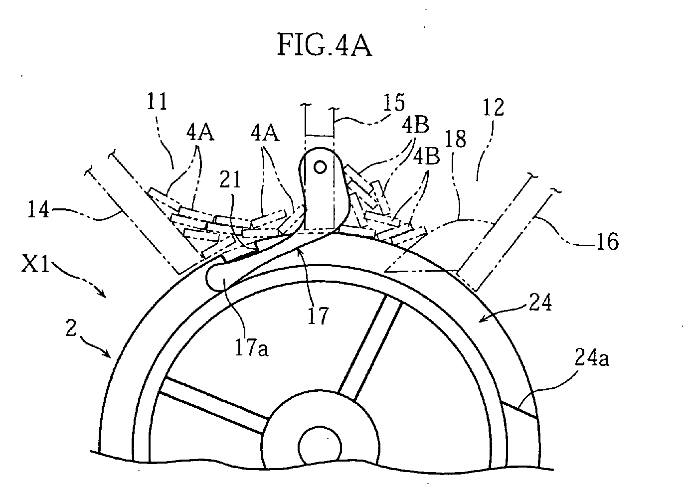
- the cutouts 24 are formed at axially opposite ends 2a of the rotating member 2 and extend along a substantially one half of the circumference. Therefore, by appropriately positioning the cutouts 24 through the rotation of the rotating member 2, it is possible to choose one of two states, i.e., the state in which the lift portions 17a of the arms 17 are received in the cutouts 24 as shown in Fig. 4A and the state in which the lift portions 17a of the arms 17 ride on the circumferential surface of the rotating member 2 as shown in Fig. 4B.
- the ends 24a of each cutout 24 in the circumferential direction are formed as inclined surfaces. Therefore, when the rotating member 2 is rotated, the transition between the state shown in Fig. 4A and the state shown in Fig. 4B is smooth.
- the depth (dimension in the radial direction of the rotating member 2) of the cutouts 24 is so set that the lift portions 17a of the arms 17 is located radially inward relative to the circumferential surface of the rotating member 2. Therefore, when the lift portions 17a of the arms 17 are received in the cutouts 24, it is possible to load the test tools 4A of the first storage space 11 onto the first loading portion 21 without being hindered by the arms 17.
- the lift portions 17a of the arms 17 ride on the circumferential surface of the rotating member 2 as shown in Fig. 4B, the test tools 4A in the first storage space 11 are lifted by the arms 17.
- the second loading portion 22 moves under the arms 17, so that the test tools 4A are not loaded into the second loading portion 22. Therefore, in the test tool feeder X1, by adjusting the positional relationship between the arms 17 and the cutouts 24, selection can be made between the state in which the test tools 4A are taken out from the first storage space 11 and the state in which the test tools 4A are not taken out.
- cutouts 24 are formed over a substantially one half of the circumference of the rotating member 2, and the first and the second loading portions 21 and 22 are formed at the center of the first region (which is formed with the cutouts 24) or the second region (which is not formed with the cutouts 24) of the circumferential surface of the rotating member 2. Therefore, as understood from Figs. 5A-5C showing the operation for taking out the test tools 4A from the first storage space 11, when the rotating member 2 is rotated within a range in which the lift portions 17a of the arms 17 are received in the cutouts 24, the second loading portion 22 does not come under the second storage space 12. Therefore, during the rotation within this rotation range, the test tools 4B are not taken out from the second storage space 12.
- Figs. 6A-6D showing the operation for taking out the test tools 4B from the second storage space 12
- the rotating member 2 when the rotating member 2 is rotated within a range in which the lift portions 17a of the arms 17 ride on the circumferential surface of the rotating member 2, the second loading portion 22 can position under the second storage space 12, while the test tools 4A in the first storage space 11 are lifted. Therefore, during the rotation within this rotation range, the test tools 4B can be taken out from the second storage space 12 and transported.
- the secondary transport mechanism 3 defines a path along which the test tools 4A, 4B taken out from the first and the second storage spaces 11, 12 by the rotating member 2 are transported to an intended position.
- the secondary transport mechanism 3 includes a main body 30, a block member 31 and a reverse member 32.
- the main body 30 includes a standing portion 30A, a holder portion 30B and a final transport portion 30C.
- the standing portion 30A guides the test tools 4A, 4B loaded on the first or the second loading portion 21, 22 to the reverse member 32.
- the standing portion 30A has an end 30Aa provided with blades 30Ab.
- the blades 30Ab serve to scrape off the test tools 4A, 4B from the first or the second loading portions of the rotating member 2.
- the blades 30Ab are arranged to be received in the grooves 23 of the rotating member 2.
- the holder portion 30B rotatably holds the reverse member 32.
- the final transport portion 30C is utilized for transporting the test tools 4A, 4B from the reverse member 32.
- the block member 31 prevents the test tools 4A, 4B unloaded from the rotating member 2 from falling out of the secondary transport mechanism 3.
- the block member 31 is disposed to face the standing portion 30A of the main body 30.
- the reverse member 32 having a columnar appearance, turns over the test tool in accordance with the detection result from the detector 14A.
- the reverse member 32 is formed with a storage space 32a which penetrates the reverse member in the radial direction and extends in the axial direction of the reverse member.
- the test tool 4A, 4B dropped from the rotating member 2 is stored in the storage space 32a of the reverse member 32 and turned over, as required, by rotating the reverse member 32 in an appropriate direction.
- the rotational force from a motor is transmitted to the rotation shaft (not shown) of the reverse member 32.
- the reverse member 32 is rotatable in the forward direction A and the backward direction B by the output from the motor.
- the control of rotation of the reverse member 32 in the forward direction A and the backward direction B may be performed in a similar manner to the control of rotation of the rotating member 2.
- the motor the motor 26 (See Fig. 3) for rotating the rotating member 2 may be utilized.
- another motor may be provided separately from the motor 26 (See Fig. 3) for rotating the rotating member 2.
- the test tool feeder X1 chooses a required kind of test tools 4A or 4B from two kinds of test tools 4A and 4B respectively stored in the first and the second storage spaces 11 and 12, and transport and feed the chosen test tools 4A or 4B one by one.
- the first transport operation for selectively taking out and transporting the test tools 4A from the first storage space 11 will be described below with reference to Figs. 5A-5C
- the second transport operation for selectively taking out and transporting the test tools 4B from the second storage space 12 will be described below with reference to Figs. 6A-5D.
- the choice of the first transport operation or the second transport operation may be performed by the user's operation of an operation button (not shown) provided at the test tool feeder X, for example.
- the choice of the first transport operation or the second transport operation may be performed automatically by the test tool feeder X.
- the analytical apparatus may read the analyte information applied to the analyte container as a bar code and refers to the host computer for the analyte information.
- the test tool feeder X may receive the information as to which of the test tools 4A, 4B should be used for the analysis of the analyte and automatically select the test tools 4A or 4B to be used.
- the controller 27 (See Fig. 3) restricts the rotation of the rotating member 2 to the range in which the lift portions 17a of the arms 17 are kept received in the cutouts 24 of the rotating member 2. In this state, the test tools 4A are taken out from the first storage space 11 and transported.
- the first loading portion 21 is positioned directly below the first storage space 11, as shown in Fig. 5A, to make the first loading portion ready for receiving the test tool 4A.
- the first loading portion 21 is moved reciprocally several times by rotating the rotating member 2 in the forward direction A and the backward direction B through a small angle under the control of the controller 27 (See Fig. 3).
- the controller 27 rotates the rotating member 2 in the forward direction A to move the first loading portion 21 to a position which faces the detector 14A.
- the detector 14A first detects whether or not the test tool 4A is loaded onto the loading portion 21.
- the detector 4A detects which side i.e., obverse or reverse of the test tool 4A is facing outward.
- the controller 27 rotates the rotating member 2 in the backward direction B to return the rotating member to the state shown in Fig. 5A, and controls the rotation of the rotating member 2 again to load the test tool 4A onto the first loading portion 21.
- the controller 27 (See Fig. 3) further rotates the rotating member 2 in the forward direction A to transport the first loading portion 21 and the test tool 4A to a position which faces the block member 31 of the secondary transport mechanism 3, as shown in Fig. 5C.
- the test tool 4A falls from the first loading portion 21 by gravity due to its own weight or is scraped off by the blades 30Ab of the secondary transport mechanism 3 to be transported into the secondary transport mechanism 3.
- the test tool 4A is guided to the storage space 32a of the reverse member 32 by the block member 31 and the standing portion 30A for storage in the storage space 32a.
- the reverse member 32 is rotated in the forward direction A or the reverse direction B to transport the test tool 4A to the final transport portion 30C.
- the detector 14A detects that the obverse side of the test tool 4A is facing outward
- the reverse member 32 is rotated in the backward direction B.
- the analyzer 4A detects that the reverse side of the test tool 4A is facing outward
- the reverse member is rotated in the forward direction A.
- the controller 27 (See Fig. 3) restricts the rotation of the rotating member 2 to the range in which the lift portions 17a of the arms 17 ride on the circumferential surface of the rotating member 2.
- the test tools 4B are taken out from the second storage space 12 and transported.
- the second loading portion 22 is positioned directly below the second storage space 12, as shown in Fig. 6A, to make the second loading portion ready for receiving the test tool 4B.
- the second loading portion 22 is moved reciprocally several times by rotating the rotating member 2 in the forward direction A and the backward direction B through a small angle.
- the controller 27 (See Fig. 3) rotates the rotating member 2 in the forward direction A so that the second loading portion 22 passes below the first storage space 11. Since the lift portions 17a of the arms 17 are rest on the circumferential surface of the rotating member 2, the test tools 4A in the first storage space 11 are lifted by the arms 17. Therefore, even when the test tool 4B is not loaded onto the second loading portion 22, the test tool 4A of the first storage space 11 is not loaded onto the second loading portion 22.
- the controller 27 (See Fig. 3) further rotates the rotating member 2 in the forward direction A to move the second loading portion 22 to a position which faces the detector 14A.
- the subsequent operations are performed similarly to the first transport operation. Specifically, after the detection by the detector 14A, the rotation direction of the reverse member 32 is controlled based on the detection result of the detector 14A to make the obverse side of the test tool 4B face outward, and the test tool 4B is transported to the final transport path 30C.
- the storage portion 1 can store two kinds of test tools, and the test tools 4A or 4B can be selectively taken out from the relevant storage spaces 11, 12. Therefore, to change the kind of test tools to be fed to e.g. the analytical apparatus, it is only necessary to designate from which of the storage spaces 11 and 12 the test tools 4A, 4B are to be taken out by operating the operation button, for example. Therefore, unlike the prior art device, to change the kind of test tools in the test tool feeder X1, it is unnecessary to replace the test tools stored in the storage portion or replace the test tool bottle attached to the test tool feeder. Therefore, in the test tool feeder X1, the troublesome work to change the kind of test tools can be eliminated, whereby the operation efficiency can be enhanced.
- the test tool feeder X2 shown in Figs. 7A and 7B includes an arm 17' having two lift portions 17a' and 17b' , and a rotating member 2' having an end in the axial direction which is formed with a cutout 24' extending over the entire circumference.
- the arm 17' is driven by a non-illustrated actuator.
- the test tool feeder X3 shown in Figs. 8A and 8B includes a storage portion 5 and a movable block 6.
- the storage portion 5 includes a first through a third walls 51, 52 and 53.
- the walls 51-53 define a first and a second storage spaces 54 and 55.
- the first and the second storage spaces 54 and 55 store different kinds of test tools 4A and 4B.
- the second wall 52 is formed with a cutout 52A.
- An arm 17 is supported in the cutout 52A.
- the block 6 is movable in the arrow CD direction in the figures and includes a first and a second loading portions 61 and 62 and a recess 63.
- the first loading portion 61 serves to carry the test tools 4A stored in the first storage space 54 and is provided at a position corresponding to the portion formed with the recess 63, as viewed in side.
- the second loading portion 62 serves to carry the test tools 4B stored in the second storage space 55 and is spaced from the portion formed with the recess 63, as viewed in side.
- the recess 63 can accommodate the lift portion 17a of the arm 17.
- test tool feeder X3 by controlling the movement range of the movable block 6, it is possible to select between the state in which the test tools 4A are taken out from the first storage space 54 as shown in Figs. 8A and 8B and the state in which the test tools 4B are taken out from the second storage space 55 as shown in Figs. 9A and 9B.
- the first loading portion 61 is positioned below the first storage space 54, as shown in Fig. 8A.
- the lift portion 17a of the arm 17 is received in the recess 63 so that the test tools 4A are allowed to come into contact with the upper surface of the movable block 6. Therefore, the test tool 4A is loaded onto the first loading portion 61.
- the movable block 6 is moved in the arrow C direction in the figure, whereby the test tool 4A is taken out from the first storage space 54.
- the second loading portion 62 is positioned below the second storage space 55 as shown in Fig. 9A to load the test tool 4B onto the second loading portion 62. Subsequently, as shown in Figs. 9B and 9C, the movable block 6 is moved in the arrow C direction in the figures, whereby the test tool 4B is taken out from the second storage space 55. As shown in Fig. 9B, when the movable block 6 moves in the above manner, the second loading portion 62 passes below the first storage space 54. Since the lift portion 17a of the arm 17 is positioned on the upper surface of the movable block 6, the test tools 4A of the first storage space 54 are lifted. Therefore, even when the second loading portion 62 passes below the first storage space 54 without carrying the test tool 4B, the test tool 4A of the first storage space 54 is not loaded onto the second loading position 62.
- test tool feeder X4 shown in Figs. 10A and 10B includes a storage portion 5' and a movable block 6'.
- the storage portion 5' includes a first and a second storage spaces 54' and 55' having a uniform cross section conforming to the configuration, as viewed in plan, of the test tools 4A, 4B. Therefore, the first and the second storage spaces 54' and 55' can store the test tools 4A and 4B in a neatly stacking manner.
- the storage portion 5' includes a center wall 52' supporting an arm 17.
- the arm 17 includes a lift portion 17a which can be pivoted by the motive power from a non-illustrated actuator.
- the movable block 6' includes a single loading portion 61' and a recess 63'.
- the state in which the test tools 4A are taken out from the first storage space 54' or the state in which the test tools 4B are taken out from the second storage space 55' can be selected by controlling the movement range of the loading portion 61' and selecting the state in which the arm 17 lifts the test tools 4A or the state in which the arm 17 does not lift the test tools 4A.
- the storage portion 1' includes a single storage space 11'.
- the storage space 11' is defined by two support members 13' (only one of the support members 13' is shown in the figures) and a first and a second members 14' and 15' fixed between the support members 13'.
- the second support member 15' supports an arm 17'.
- the arm 17' includes a lift portion 17a' which can be pivoted by a non-illustrated actuator. By the pivotal movement of the lift portion 17a', selection can be made between the state in which the lift portion 17a' is received in a recess 24' of the rotating member 2' and the state in which the lift portion 17' is not received in the recess 24'.
- the lift portion 17a' lifts the test tools 4' of the accommodation space 11' when not received in the recess 24' and does not lift the test tools 4' when received in the recess 24'.
- test tool feeder X5 by alternately selecting the state in which the test tools 4' are lifted and the state in which the test tools are not lifted, the test tools 4' in the storage space 11' can be shaken and aligned within the storage space 11'.
- the present invention is not limited to the foregoing embodiments and may be modified in various ways.
- the number of the storage spaces in the storage portion and the number of loading portions may be varied as long as the object can be achieved.
- three or more storage spaces or loading portions may be provided.
- the member for lifting the test tools is not limited to an arm.
- a plate member may be disposed to be movable toward and away from the transporting member such as a rotating member or a movable block. In this case, by selecting the position of the plate member, selection can be made between the state in which the test tools are lifted and the state in which the test tools are not lifted.
- the configuration of the arm is not limited to those described in the foregoing embodiments.
- the test tool feeder of the present invention is applicable not only to the feeding of a test piece provided with a reagent pad but also applicable to the feeding of a Lab-on-a Chip or a DNA chip, for example.
Abstract
Description
- The present invention relates to an analyzer-feeding device provided with storage portions to store a plurality of test tools and provided with a transporting member to take out and transport analyzers from the storage portions.
- Urinalysis can be performed by impregnating a reagent pad of a test tool with urine, and then checking the color change of the pad by an optical method. Such optical urinalysis may be performed by using an analytical apparatus in which test tools are successively transported to a measurement point, where the color change of the reagent pad is automatically checked. Such an analytical apparatus often incorporates a test tool feeder for automatically feeding test tools to the measurement point.
- Fig. 11 of the present application shows an example of a test tool feeder (See JP-A 2000-35433, for example). The illustrated
test tool feeder 9 includes a rotatingmember 92 formed with agroove 91 for receiving asingle test tool 90, and astorage portion 93 for accommodating a plurality oftest tools 90. In thetest tool feeder 9, by rotating therotating member 92, thegroove 91 is brought to a position corresponding to thestorage portion 93, whereby one of thetest tools 90 is received in thegroove 91. When he rotatingmember 92 is rotated further from this state, thetest tool 90 falls from the rotatingmember 92 to slide down on aslope 94. In this way, in thetest tool feeder 9, thetest tools 90 are taken out from thestorage portion 93 one by one by successively rotating the rotatingmember 92. - The
test tool feeder 9 is designed to store a single kind oftest tools 90 in thestorage portion 93 and take out the single kind of test tools. Therefore, to use test tools of a kind different from those currently used, it is necessary to remove the test tools from thestorage portion 93 and load the different kind of test tools into thestorage portion 93. Therefore, in changing the kind of test tools in thetest tool feeder 9, the troublesome work of replacing test tools need be performed, and the operation efficiency is deteriorated. - To solve the above problems, a test tool feeder has been proposed which includes a test tool bottle for storing test tools, which is removably mounted so as to be replaced with another bottle when another kind of test tools are to be used (See JP-A-H09-325152, for example). Although this kind of test tool feeder can eliminate the troublesome work of changing the test tools, it suffers another troublesome work of changing test tool bottles, and hence, still has room for improvement.
- An object of the present invention is to provide a test tool feeder which makes it possible to use different kinds of test tools without requiring the user's troublesome work.
- According to a first aspect of the present invention, there is provided a test tool feeder comprising: a storage portion for storing a plurality of test tools; and a transporting member provided with at least one loading portion for loading the test tools stored in the storage portion, where the transporting member transports the test tools one by one. The storage portion includes a plurality of storage spaces each storing a plurality of test tools.
- Preferably, in the test tool feeder, each of the storage spaces is selectively brought into a state in which the test tools are taken out from the storage space and a state in which the test tools are not taken out from the storage space.
- According to a second aspect of the present invention, there is provided a test tool feeder comprising a storage portion for storing a plurality of test tools, and a transporting member for transporting the test tools individually. In the test tool feeder, selection can be made between a state in which the test tools are taken out from the storage space and a state in which the test tools are not taken out from the storage space.
- For instance, the state in which the test tools are not taken out from the storage space is achieved by lifting the test tools stored in the storage space so that the test tools do not come into contact with the transporting member. The state in which the test tools are taken out from the storage space is achieved by bringing at least some of the test tools stored in the storage space into contact with the transporting member.
- For instance, the transporting member comprises a rotating member. The transporting member may transport the test tools horizontally.
- The test tool feeder according to the present invention may further comprise a movable member for lifting the test tools stored in at least one of the plurality of storage spaces.
- The movable member may include at least one pivotable lift portion. In this case, the transporting member includes a recess for receiving the lift portion.
- For instance, in the test tool feeder according to the present invention, the test tools stored in the storage space are held in contact with the transporting member when the lift portion is received in the recess, whereas the test tools stored in the storage space are lifted by the movable member so as not to come into contact with the transporting member when the lift portion is not received in the recess.
- The lift portion of the movable member is held in contact with the transporting member by gravity. The lift portion of the movable member may be pivoted by an actuator.
- In the case where the transporting member comprises a rotating member, the lift portion is positioned closer to the center of the rotating member than the circumferential surface of the rotating member when the lift portion is received in the recess. In the case where the transporting member transports the test tools horizontally, the lift portion is positioned lower than an upper surface of the transportingmember when the lift portion is received in the recess.
- For instance, the selection between the state in which the test tools are taken out from the storage space and the state in which the test tools are not taken out from the storage space is made by controlling the movable range of the at least one loading portion.
- For instance, the plurality of storage spaces include a first and a second storage spaces. For instance, the at least one loading portion includes a first loading portion for loading the test tools stored in the first storage space, and a second loading portion for loading the test tools stored in the second storage space.
- The first storage space and the second storage space are separated by a partition member disposed in the storage portion. In this case, the movable member is supported by the partition member. For instance, the movable member may be capable of lifting the test tools stored in one of the first and the second storage spaces.
- In the case where the transporting member comprises a rotating member, the rotating member may be made rotatable in both a forward direction and a reverse direction. Preferably, in this case, the test tool feeder further comprises a rotation controller for controlling a rotation direction and a rotation angle of the rotating member to control the movable range of the first and the second loading portions.
- For instance, the rotation controller controls the rotation direction and the rotation angle of the rotating member in a first movable range in which the lift portion is held in contact with a circumferential surface of the rotating member or in a second movable range in which the lift portion is received in the recess. In the first movable range, test tools are not taken out from the first storage space while test tools are taken out from the second storage space. In the second movable range, test tools are taken out from the first storage space while test tools are not taken out from the second storage space.
- The at least one lift portion includes a first lift portion for lifting the plurality of test tools stored in the first storage space, and a second lift portion for lifting the plurality of test tools stored in the second storage space. In this case, the first and the second lift portions may be pivoted by an actuator.
- When one of the first and the second lift portions lifts the test tools stored in the first and the second storage spaces, the other one of the first and the second lift portions does not lift the test tools stored in the first and the second storage spaces.
-
- Fig. 1 is an entire perspective view, partially in phantom, of a test tool feeder according to a first embodiment of the present invention.
- Fig. 2 is a side view, partially in section, of the test tool feeder shown in Fig. 1.
- Fig. 3 is a plan view, partially in phantom, of the test tool feeder shown in Fig. 1.
- Figs. 4A and 4B are side views of a principal portion for describing the operation of an arm and a cutout of the rotating member of the test tool feeder shown in Fig. 1.
- Figs. 5A-5C are partially sectional views for describing the operation to take out and transport test tools from a first storage space of the test tool feeder shown in Fig. 1.
- Figs. 6A-6D are partially sectional views for describing the operation to take out and transport test tools from a second storage space of the test tool feeder shown in Fig. 1.
- Figs. 7A and 7B are side views of a principal portion for describing a test tool feeder according to a second embodiment of the present invention.
- Figs. 8A and 8B are side views of a principal portion for describing a test tool feeder according to a third embodiment of the present invention.
- Figs. 9A-9C are side views of a principal portion for describing a test tool feeder according to the third embodiment of the present invention.
- Figs. 10A and 10B are side views of a principal portion for describing a test tool feeder according to a fourth embodiment of the present invention.
- Figs. 11A and 11B are side views of a principal portion for describing a test tool feeder according to a fifth embodiment of the present invention.
- Fig. 12 is a sectional view for describing a conventional test tool feeder.
-
- Best mode for carrying out the present invention will be described below as a first though a fifth embodiments with reference to the accompanying drawings.
- First, referring to Figs. 1-6, a first embodiment of the present invention will be described.
- The test tool feeder X1 shown in Figs. 1-3 is used as incorporated in or connected to an analytical apparatus, for example. Though not illustrated in the figures, each of
test tools - The test tool feeder X1, designed to choose a desired kind of test tools from two kinds of
test tools test tools storage portion 1, a rotatingmember 2 and asecondary transport mechanism 3. - The
storage portion 1 stores a plurality oftest tools second storage spaces second storage spaces member 2. The first and thesecond storage spaces support members 13 and a first through a third members 14-16 fixed between thesupport members 13. The first and thesecond storage spaces test tools - As shown in Fig. 2, a
detector 14A is attached to thefirst member 14. Thedetector 14A detects whether or not atest tool member 2, while also detecting whether thetest tool member 2 is showing its obverse side or reverse side. Thedetector 14A may not necessarily be provided at thefirst member 14. - As shown in Figs. 1 and 2, the
second member 15 is formed with cutouts 15Aa at its both ends 15A. In each of the cutouts 15Aa, apivot arm 17 is provided. Thearm 17, including alift portion 17a, is utilized for lifting thetest tools 4A (See Fig. 2) stored in thefirst storage space 11. Thelift portion 17a is held in contact with the rotatingmember 2 by gravity due to its own weight. - As shown in Figs. 2 and 3, the
third member 16 is provided withguide pieces 18 projecting into thesecond storage space 12. Theguide pieces 18 regulate the rotational state of the rotatingmember 2 by cooperating withgrooves 23 of the rotatingmember 2, as described below, and prevent thetest tools 4B stored in the second storage space 12 (See Fig. 2) from being unintentionally taken out from thesecond storage space 12 when the rotatingmember 2 is rotated in a backward direction B. - As shown in Figs. 1-3, the rotating
member 2 is utilized for taking out and transporting thetest tools storage portion 1. The rotatingmember 2 includes arotation shaft 20, a first and asecond loading portions cutouts 24. - The
rotation shaft 20 supports therotatingmember 2 between thesupport members 13 and has itsends 20a rotatably inserted in thesupport members 13. As shown in Fig 3, therotation shaft 20 is connected to amotor 26 viagears motor 26 is controlled by acontroller 27 to regulate the rotation direction and rotation output of therotation shaft 26a. Thus, the rotatingmember 2 is rotatable in the forward direction A and the backward direction B by the rotational force from themotor 26. - The rotation of the rotating
member 2 in the forward direction A and the backward direction B may be controlled by changing the meshing of gears in a gear mechanism provided between therotation shaft 20 of the rotatingmember 2 and themotor 26. - As shown in Figs. 1 and 3, each of the first and the
second loading portions member 2 to extend axially of the rotatingmember 2, is used for carrying onetest tool second storage space second loading portions rotation shaft 20, as viewed in the axial direction of the rotatingmember 2. Specifically, thefirst loading portion 21 is formed at a middle of a first region of the cylindrical surface of the rotatingmember 2, the region formed with thecutouts 24, whereas thesecond loading portion 22 is formed at a middle of a second region of the cylindrical surface of the rotatingmember 2, the region without thecutouts 24. The first and thesecond loading portions member 2. The positions and movable ranges of the first and thesecond loading portions member 2. - As shown in Figs. 2 and 3, the
guide grooves 23 receive theguide pieces 18 of thethird member 16 and blades 30Ab of thesecondary transport mechanism 3, as described later, and the grooves are formed in the cylindrical surface of the rotatingmember 2 to entirely circle the cylindrical member circumferentially. Thus, in rotating themember 2, theguide pieces 18 and the blades 30Ab do not interfere with the rotation of the rotatingmember 2, while also preventing the rotatingmember 2 from moving in the axial direction of the rotatingmember 2. - The
cutouts 24 can accommodate thelift portions 17a of thearms 17. Thecutouts 24 are formed at axially opposite ends 2a of the rotatingmember 2 and extend along a substantially one half of the circumference. Therefore, by appropriately positioning thecutouts 24 through the rotation of the rotatingmember 2, it is possible to choose one of two states, i.e., the state in which thelift portions 17a of thearms 17 are received in thecutouts 24 as shown in Fig. 4A and the state in which thelift portions 17a of thearms 17 ride on the circumferential surface of the rotatingmember 2 as shown in Fig. 4B. The ends 24a of eachcutout 24 in the circumferential direction are formed as inclined surfaces. Therefore, when the rotatingmember 2 is rotated, the transition between the state shown in Fig. 4A and the state shown in Fig. 4B is smooth. - As shown in Fig 4A, the depth (dimension in the radial direction of the rotating member 2) of the
cutouts 24 is so set that thelift portions 17a of thearms 17 is located radially inward relative to the circumferential surface of the rotatingmember 2. Therefore, when thelift portions 17a of thearms 17 are received in thecutouts 24, it is possible to load thetest tools 4A of thefirst storage space 11 onto thefirst loading portion 21 without being hindered by thearms 17. When thelift portions 17a of thearms 17 ride on the circumferential surface of the rotatingmember 2 as shown in Fig. 4B, thetest tools 4A in thefirst storage space 11 are lifted by thearms 17. With such an arrangement, when the rotatingmember 2 is rotated, thesecond loading portion 22 moves under thearms 17, so that thetest tools 4A are not loaded into thesecond loading portion 22. Therefore, in the test tool feeder X1, by adjusting the positional relationship between thearms 17 and thecutouts 24, selection can be made between the state in which thetest tools 4A are taken out from thefirst storage space 11 and the state in which thetest tools 4A are not taken out. - As noted above, in the rotating
member 2,cutouts 24 are formed over a substantially one half of the circumference of the rotatingmember 2, and the first and thesecond loading portions member 2. Therefore, as understood from Figs. 5A-5C showing the operation for taking out thetest tools 4A from thefirst storage space 11, when the rotatingmember 2 is rotated within a range in which thelift portions 17a of thearms 17 are received in thecutouts 24, thesecond loading portion 22 does not come under thesecond storage space 12. Therefore, during the rotation within this rotation range, thetest tools 4B are not taken out from thesecond storage space 12. On the other hand, as understood from Figs. 6A-6D showing the operation for taking out thetest tools 4B from thesecond storage space 12, when the rotatingmember 2 is rotated within a range in which thelift portions 17a of thearms 17 ride on the circumferential surface of the rotatingmember 2, thesecond loading portion 22 can position under thesecond storage space 12, while thetest tools 4A in thefirst storage space 11 are lifted. Therefore, during the rotation within this rotation range, thetest tools 4B can be taken out from thesecond storage space 12 and transported. - As shown in Figs. 1 and 2, the
secondary transport mechanism 3 defines a path along which thetest tools second storage spaces member 2 are transported to an intended position. Thesecondary transport mechanism 3 includes amain body 30, ablock member 31 and areverse member 32. - The
main body 30 includes a standingportion 30A, aholder portion 30B and afinal transport portion 30C. The standingportion 30A guides thetest tools second loading portion reverse member 32. As shown in Figs. 2 and 3, the standingportion 30A has an end 30Aa provided with blades 30Ab. The blades 30Ab serve to scrape off thetest tools member 2. As noted above, the blades 30Ab are arranged to be received in thegrooves 23 of the rotatingmember 2. As shown in Figs. 1 and 2, theholder portion 30B rotatably holds thereverse member 32. Thefinal transport portion 30C is utilized for transporting thetest tools reverse member 32. - The
block member 31 prevents thetest tools member 2 from falling out of thesecondary transport mechanism 3. Theblock member 31 is disposed to face the standingportion 30A of themain body 30. - The
reverse member 32, having a columnar appearance, turns over the test tool in accordance with the detection result from thedetector 14A. Thereverse member 32 is formed with astorage space 32a which penetrates the reverse member in the radial direction and extends in the axial direction of the reverse member. Thus, thetest tool member 2 is stored in thestorage space 32a of thereverse member 32 and turned over, as required, by rotating thereverse member 32 in an appropriate direction. The rotational force from a motor is transmitted to the rotation shaft (not shown) of thereverse member 32. Thus, thereverse member 32 is rotatable in the forward direction A and the backward direction B by the output from the motor. The control of rotation of thereverse member 32 in the forward direction A and the backward direction B may be performed in a similar manner to the control of rotation of the rotatingmember 2. As the motor, the motor 26 (See Fig. 3) for rotating the rotatingmember 2 may be utilized. Alternatively, another motor may be provided separately from the motor 26 (See Fig. 3) for rotating the rotatingmember 2. - As noted above, the test tool feeder X1 chooses a required kind of
test tools test tools second storage spaces test tools test tools 4A from thefirst storage space 11 will be described below with reference to Figs. 5A-5C, whereas the second transport operation for selectively taking out and transporting thetest tools 4B from thesecond storage space 12 will be described below with reference to Figs. 6A-5D. - The choice of the first transport operation or the second transport operation may be performed by the user's operation of an operation button (not shown) provided at the test tool feeder X, for example. Alternatively, the choice of the first transport operation or the second transport operation may be performed automatically by the test tool feeder X. Specifically, the analytical apparatus may read the analyte information applied to the analyte container as a bar code and refers to the host computer for the analyte information. The test tool feeder X may receive the information as to which of the
test tools test tools - As shown in Figs. 5A-5C, in the first transport operation, the controller 27 (See Fig. 3) restricts the rotation of the rotating
member 2 to the range in which thelift portions 17a of thearms 17 are kept received in thecutouts 24 of the rotatingmember 2. In this state, thetest tools 4A are taken out from thefirst storage space 11 and transported. - Specifically, in the first transport operation, the
first loading portion 21 is positioned directly below thefirst storage space 11, as shown in Fig. 5A, to make the first loading portion ready for receiving thetest tool 4A. Preferably, to reliably load thetest tool 4A onto thefirst loading portion 21, thefirst loading portion 21 is moved reciprocally several times by rotating the rotatingmember 2 in the forward direction A and the backward direction B through a small angle under the control of the controller 27 (See Fig. 3). - Subsequently, as shown in Fig. 5B, the controller 27 (See Fig. 3) rotates the rotating
member 2 in the forward direction A to move thefirst loading portion 21 to a position which faces thedetector 14A. Thedetector 14A first detects whether or not thetest tool 4A is loaded onto theloading portion 21. When thedetector 14A detects that thetest tool 4A is loaded onto thefirst loading portion 21, thedetector 4A then detects which side i.e., obverse or reverse of thetest tool 4A is facing outward. On the other hand, when thedetector 14A detects that thetest tool 4A is not loaded onto thefirst loading portion 21, the controller 27 (See Fig. 3) rotates the rotatingmember 2 in the backward direction B to return the rotating member to the state shown in Fig. 5A, and controls the rotation of the rotatingmember 2 again to load thetest tool 4A onto thefirst loading portion 21. - After the
detector 14A detects which side of theanalyzer 4A is facing outward, the controller 27 (See Fig. 3) further rotates the rotatingmember 2 in the forward direction A to transport thefirst loading portion 21 and thetest tool 4A to a position which faces theblock member 31 of thesecondary transport mechanism 3, as shown in Fig. 5C. By this rotation, thetest tool 4A falls from thefirst loading portion 21 by gravity due to its own weight or is scraped off by the blades 30Ab of thesecondary transport mechanism 3 to be transported into thesecondary transport mechanism 3. Specifically, thetest tool 4A is guided to thestorage space 32a of thereverse member 32 by theblock member 31 and the standingportion 30A for storage in thestorage space 32a. Then, based on the result of detection by thedetector 14A, thereverse member 32 is rotated in the forward direction A or the reverse direction B to transport thetest tool 4A to thefinal transport portion 30C. Specifically, when thedetector 14A detects that the obverse side of thetest tool 4A is facing outward, thereverse member 32 is rotated in the backward direction B. When theanalyzer 4A detects that the reverse side of thetest tool 4A is facing outward, the reverse member is rotated in the forward direction A. By such operation, thetest tool 4A is transported to thefinal transport portion 30C with the obverse side thereof facing outward. - As shown in Figs. 6A-6D, in the second transport operation, the controller 27 (See Fig. 3) restricts the rotation of the rotating
member 2 to the range in which thelift portions 17a of thearms 17 ride on the circumferential surface of the rotatingmember 2. In this state, thetest tools 4B are taken out from thesecond storage space 12 and transported. - Firstly, in the second transport operation, the
second loading portion 22 is positioned directly below thesecond storage space 12, as shown in Fig. 6A, to make the second loading portion ready for receiving thetest tool 4B. Preferably, to reliably load thetest tool 4B onto thesecond loading portion 22, thesecond loading portion 22 is moved reciprocally several times by rotating the rotatingmember 2 in the forward direction A and the backward direction B through a small angle. - Subsequently, as shown in Fig. 6B, the controller 27 (See Fig. 3) rotates the rotating
member 2 in the forward direction A so that thesecond loading portion 22 passes below thefirst storage space 11. Since thelift portions 17a of thearms 17 are rest on the circumferential surface of the rotatingmember 2, thetest tools 4A in thefirst storage space 11 are lifted by thearms 17. Therefore, even when thetest tool 4B is not loaded onto thesecond loading portion 22, thetest tool 4A of thefirst storage space 11 is not loaded onto thesecond loading portion 22. - Subsequently, as shown in Fig. 6C, the controller 27 (See Fig. 3) further rotates the rotating
member 2 in the forward direction A to move thesecond loading portion 22 to a position which faces thedetector 14A. As can be anticipated from Figs. 6C and 6D, the subsequent operations are performed similarly to the first transport operation. Specifically, after the detection by thedetector 14A, the rotation direction of thereverse member 32 is controlled based on the detection result of thedetector 14A to make the obverse side of thetest tool 4B face outward, and thetest tool 4B is transported to thefinal transport path 30C. - In the test tool feeder X1, the
storage portion 1 can store two kinds of test tools, and thetest tools relevant storage spaces storage spaces test tools - Next, a second embodiment of the present invention will be described with reference to Figs. 7A and 7B.
- The test tool feeder X2 shown in Figs. 7A and 7B includes an arm 17' having two
lift portions 17a' and 17b' , and a rotating member 2' having an end in the axial direction which is formed with a cutout 24' extending over the entire circumference. The arm 17' is driven by a non-illustrated actuator. With such an arrangement, selection can be made between the state in which one of theoperative portions 17a' is received in the cutout 24' as shown in Fig. 7A and the state in which the other one of theoperative portions 17b' is received in the cutout 24'. Thus, selection can be made between the state in which thetest tools 4A of thefirst storage space 11 are lifted and the state in which thetest tools 4B of thesecond storage space 12 are lifted. Therefore, it is possible to select the state in which thetest tools 4A are taken out from thestorage space 11 or the state in which thetest tools 4B are taken out from thestorage space 12. - Next, with reference to Figs. 8A and 8B and Figs. 9A and 9B, a third embodiment of the present invention will be described.
- The test tool feeder X3 shown in Figs. 8A and 8B includes a
storage portion 5 and amovable block 6. - The
storage portion 5 includes a first through athird walls second storage spaces second storage spaces test tools second wall 52 is formed with a cutout 52A. Anarm 17 is supported in the cutout 52A. - The
block 6 is movable in the arrow CD direction in the figures and includes a first and asecond loading portions recess 63. Thefirst loading portion 61 serves to carry thetest tools 4A stored in thefirst storage space 54 and is provided at a position corresponding to the portion formed with therecess 63, as viewed in side. Thesecond loading portion 62 serves to carry thetest tools 4B stored in thesecond storage space 55 and is spaced from the portion formed with therecess 63, as viewed in side. Therecess 63 can accommodate thelift portion 17a of thearm 17. By moving themovable block 6 relative to thestorage portion 5, selection can be made between the state in which thelift portion 17a of thearm 17 is received in therecess 63 as shown in Fig. 8A and the state in which thelift portion 17a of thearm 17 is not received in therecess 63 but held in contact with the upper surface of themovable block 6 as shown in Fig. 8B. - In the test tool feeder X3, by controlling the movement range of the
movable block 6, it is possible to select between the state in which thetest tools 4A are taken out from thefirst storage space 54 as shown in Figs. 8A and 8B and the state in which thetest tools 4B are taken out from thesecond storage space 55 as shown in Figs. 9A and 9B. - Specifically, to take out the
test tools 4A from thefirst storage space 54, thefirst loading portion 61 is positioned below thefirst storage space 54, as shown in Fig. 8A. In this state, thelift portion 17a of thearm 17 is received in therecess 63 so that thetest tools 4A are allowed to come into contact with the upper surface of themovable block 6. Therefore, thetest tool 4A is loaded onto thefirst loading portion 61. Subsequently, as shown in Fig. 8B, themovable block 6 is moved in the arrow C direction in the figure, whereby thetest tool 4A is taken out from thefirst storage space 54. - To take out the
test tools 4B from thesecond storage space 55, thesecond loading portion 62 is positioned below thesecond storage space 55 as shown in Fig. 9A to load thetest tool 4B onto thesecond loading portion 62. Subsequently, as shown in Figs. 9B and 9C, themovable block 6 is moved in the arrow C direction in the figures, whereby thetest tool 4B is taken out from thesecond storage space 55. As shown in Fig. 9B, when themovable block 6 moves in the above manner, thesecond loading portion 62 passes below thefirst storage space 54. Since thelift portion 17a of thearm 17 is positioned on the upper surface of themovable block 6, thetest tools 4A of thefirst storage space 54 are lifted. Therefore, even when thesecond loading portion 62 passes below thefirst storage space 54 without carrying thetest tool 4B, thetest tool 4A of thefirst storage space 54 is not loaded onto thesecond loading position 62. - Next, a fourth embodiment of the present invention will be described below with reference to Figs. 10A and 10B.
- Similarly to the foregoing test tool feeder X3 (See Fig. 8), the test tool feeder X4 shown in Figs. 10A and 10B includes a storage portion 5' and a movable block 6'.
- The storage portion 5' includes a first and a second storage spaces 54' and 55' having a uniform cross section conforming to the configuration, as viewed in plan, of the
test tools test tools arm 17. Thearm 17 includes alift portion 17a which can be pivoted by the motive power from a non-illustrated actuator. The movable block 6' includes a single loading portion 61' and a recess 63'. - In the test tool feeder X4, the state in which the
test tools 4A are taken out from the first storage space 54' or the state in which thetest tools 4B are taken out from the second storage space 55' can be selected by controlling the movement range of the loading portion 61' and selecting the state in which thearm 17 lifts thetest tools 4A or the state in which thearm 17 does not lift thetest tools 4A. - Next, a fifth embodiment of the present invention will be described below with reference to Figs. 11A and 11B.
- In the test tool feeder X5 shown in Figs. 11A and 11B, the storage portion 1' includes a single storage space 11'. The storage space 11' is defined by two support members 13' (only one of the support members 13' is shown in the figures) and a first and a
second members 14' and 15' fixed between the support members 13'. - The second support member 15' supports an arm 17'. The arm 17' includes a
lift portion 17a' which can be pivoted by a non-illustrated actuator. By the pivotal movement of thelift portion 17a', selection can be made between the state in which thelift portion 17a' is received in a recess 24' of the rotating member 2' and the state in which the lift portion 17' is not received in the recess 24'. Thelift portion 17a' lifts the test tools 4' of the accommodation space 11' when not received in the recess 24' and does not lift the test tools 4' when received in the recess 24'. - In the test tool feeder X5, by alternately selecting the state in which the test tools 4' are lifted and the state in which the test tools are not lifted, the test tools 4' in the storage space 11' can be shaken and aligned within the storage space 11'.
- The present invention is not limited to the foregoing embodiments and may be modified in various ways. For example, the number of the storage spaces in the storage portion and the number of loading portions may be varied as long as the object can be achieved. For example, three or more storage spaces or loading portions may be provided. When a loading portion passes below the storage space storing unintended test tools, air may be jetted from the rotating member toward the storage space to prevent the unintended test tool from being loaded onto the loading portion.
- The member for lifting the test tools is not limited to an arm. For example, a plate member may be disposed to be movable toward and away from the transporting member such as a rotating member or a movable block. In this case, by selecting the position of the plate member, selection can be made between the state in which the test tools are lifted and the state in which the test tools are not lifted. Further, the configuration of the arm is not limited to those described in the foregoing embodiments.
- The test tool feeder of the present invention is applicable not only to the feeding of a test piece provided with a reagent pad but also applicable to the feeding of a Lab-on-a Chip or a DNA chip, for example.
Claims (29)
- A test tool feeder comprising: a storage portion for storing a plurality of test tools; and a transporting member provided with at least one loading portion for loading a test tool stored in the storage portion, the transporting member transporting test tools one by one;
wherein the storage portion includes a plurality of storage spaces each storing a plurality of test tools. - The test tool feeder according to claim 1, wherein each of the storage spaces is selectively brought into a state in which the test tools are taken out from the storage space and a state in which the test tools are not taken out from the storage space.
- The test tool feeder according to claim 2, wherein the state in which the test tools are not taken out from the storage space is achieved by lifting the test tools stored in the storage space so that the test tools do not come into contact with the transporting member.
- The test tool feeder according to claim 3, wherein the state in which the test tools are taken out from the storage space is achieved by bringing at least some of the test tools stored in the storage space into contact with the transporting member.
- The test tool feeder according to claim 4, wherein the transporting member comprises a rotating member.
- The test tool feeder according to claim 5, further comprising a movable member for lifting the test tools stored in at least one of the plurality of storage spaces.
- The test tool feeder according to claim 6, wherein the movable member includes at least one pivotable lift portion, and
wherein the rotating member includes a recess for receiving said at least one lift portion. - The test tool feeder according to claim 7, wherein the test tools stored in the storage space come into contact with the rotating member when the lift portion is received in the recess, and
wherein the test tools stored in the storage space are lifted by the movable member so as not to come into contact with the rotating member when the lift portion is not received in the recess. - The test tool feeder according to claim 8, wherein the lift portion of the movable member is held in contact with the rotating member by gravity.
- The test tool feeder according to claim 8, wherein, when the lift portion is received in the recess, the lift portion is positioned closer to a center of the rotating member than a circumferential surface of the rotating member.
- The test tool feeder according to claim 9, wherein the selection between the state in which the test tools are taken out from the storage space and the state in which the test tools are not taken out from the storage space is made by controlling a movable range of said at least one loading portion.
- The test tool feeder according to claim 11, wherein the plurality of storage spaces include a first and a second storage spaces, and
wherein said at least one loading portion includes a first loading portion for loading the test tools stored in the first storage space, and a second loading portion for loading the test tools stored in the second storage space. - The test tool feeder according to claim 12, wherein the first storage space and the second storage space are separated by a partition member disposed in the storage portion, and
wherein the movable member is supported by the partition member. - The test tool feeder according to claim 13, wherein the movable member is capable of lifting the test tools stored in one of the first and the second storage spaces.
- The test tool feeder according to claim 12, wherein the rotating member is rotatable in both a forward direction and a reverse direction, and
wherein the test tool feeder further comprises a rotation controller for controlling a rotation direction and a rotation angle of the rotating member to control the movable range of the first and the second loading portions. - The test tool feeder according to claim 15, wherein the rotation controller controls the rotation direction and the rotation angle of the rotating member in a first movable range in which the lift portion is held in contact with a circumferential surface of the rotating member or in a second movable range in which the lift portion is received in the recess,
wherein, in the first movable range, test tools are not taken out from the first storage space while test tools are taken out from the second storage space,
wherein, in the second movable range, test tools are taken out from the first storage space while test tools are not taken out from the second storage space. - The test tool feeder according to claim 7, wherein the plurality of storage spaces include a first and a second storage spaces, and
wherein said at least one lift portion includes a first lift portion for lifting the plurality of test tools stored in the first storage space and a second lift portion for lifting the plurality of test tools stored in the second storage space. - The test tool feeder according to claim 17, wherein the first and the second lift portions are pivoted by an actuator.
- The test tool feeder according to claim 17, wherein, when one of the first and the second lift portions lifts the test tools stored in the first and the second storage spaces, the other one of the first and the second lift portions does not lift the test tools stored in the first and the second storage spaces.
- The test tool feeder according to claim 4, wherein the transporting member transports the test tools horizontally.
- The test tool feeder according to claim20, further comprising a movable member for lifting the test tools stored in at least one of the plurality of storage spaces.
- The test tool feeder according to claim 21, wherein the movable member includes a pivotable lift portion, and
wherein the transporting member includes a recess for receiving the lift portion. - The test tool feeder according to claim 22, wherein the test tools stored in the storage space are held in contact with the transporting member when the lift portion is received in the recess, and
wherein the test tools stored in the storage space are lifted by the movable member so as not to come into contact with the transporting member when the lift portion is not received in the recess. - The test tool feeder according to claim 23, wherein when the lift portion is received in the recess, the lift portion is positioned lower than an upper surface of the transporting member.
- The test tool feeder according to claim 24, wherein the selection between the state in which the test tools are taken out from the storage space and the state in which the test tools are not taken out from the storage space is made by controlling a movable range of the loading portion.
- A test tool feeder comprising: a storage portion for storing a plurality of test tools; and a transporting member for transporting the test tools individually;
wherein selection can be made between a state in which the test tools are taken out from the storage space and a state in which the test tools are not taken out from the storage space. - The test tool feeder according to claim 26, wherein the state in which the test tools are not taken out from the storage space is achieved by lifting the test tools stored in the storage space so that the test tools do not come into contact with the transporting member, and
wherein the state in which the test tools are taken out from the storage space is achieved by bringing at least some of the test tools stored in the storage space into contact with the transporting member. - The test tool feeder according to claim 27, further comprising a movable member for lifting the test tools stored in the storage space.
- The test tool feeder according to claim 28, wherein the movable member includes a lift portion which is pivoted by an actuator.
Applications Claiming Priority (3)
| Application Number | Priority Date | Filing Date | Title |
|---|---|---|---|
| JP2003023079A JP3890369B2 (en) | 2003-01-31 | 2003-01-31 | Analyzer supply device |
| JP2003023079 | 2003-01-31 | ||
| PCT/JP2004/000724 WO2004068145A1 (en) | 2003-01-31 | 2004-01-27 | Analyzer-feeding device |
Publications (3)
| Publication Number | Publication Date |
|---|---|
| EP1589343A1 true EP1589343A1 (en) | 2005-10-26 |
| EP1589343A4 EP1589343A4 (en) | 2011-06-15 |
| EP1589343B1 EP1589343B1 (en) | 2014-03-12 |
Family
ID=32820711
Family Applications (1)
| Application Number | Title | Priority Date | Filing Date |
|---|---|---|---|
| EP04705518.1A Expired - Lifetime EP1589343B1 (en) | 2003-01-31 | 2004-01-27 | Analyzer-feeding device |
Country Status (5)
| Country | Link |
|---|---|
| US (1) | US7842239B2 (en) |
| EP (1) | EP1589343B1 (en) |
| JP (1) | JP3890369B2 (en) |
| CN (1) | CN1745304B (en) |
| WO (1) | WO2004068145A1 (en) |
Families Citing this family (5)
| Publication number | Priority date | Publication date | Assignee | Title |
|---|---|---|---|---|
| EP2028488B1 (en) * | 2007-08-02 | 2015-02-25 | F. Hoffmann-La Roche AG | Transfer unit for test elements |
| JP5155751B2 (en) * | 2008-06-26 | 2013-03-06 | 株式会社堀場製作所 | Elemental analyzer |
| US8172072B2 (en) * | 2008-06-26 | 2012-05-08 | Horiba, Ltd. | Crucible feeder mechanism |
| AU2012228413B2 (en) * | 2011-03-11 | 2015-12-10 | Qiagen Instruments Ag | Device for closing a sample receptacle with a spherical closure element |
| CN102608338B (en) * | 2012-02-23 | 2013-04-10 | 长沙高新技术产业开发区爱威科技实业有限公司 | Test paper strip separating and conveying device for full-automatic dry chemical analyzer |
Citations (2)
| Publication number | Priority date | Publication date | Assignee | Title |
|---|---|---|---|---|
| US4279514A (en) * | 1978-01-30 | 1981-07-21 | Labora Mannheim Gmbh Fur Labortechnik | Apparatus for the analysis of test tape |
| JPH01266697A (en) * | 1988-04-18 | 1989-10-24 | Sanyo Electric Co Ltd | Straw delivery device |
Family Cites Families (14)
| Publication number | Priority date | Publication date | Assignee | Title |
|---|---|---|---|---|
| JPS5757663A (en) | 1980-09-25 | 1982-04-06 | Noda Plywood Mfg Co Ltd | Manufacture of paper lined decorative board |
| US4318841A (en) | 1980-10-06 | 1982-03-09 | Celanese Corporation | Polyester of 6-hydroxy-2-naphthoic acid, para-hydroxy benzoic acid, terephthalic acid, and resorcinol capable of readily undergoing melt processing to form shaped articles having increased impact strength |
| DE3218465A1 (en) | 1982-05-15 | 1983-11-24 | Compur-Electronic GmbH, 8000 München | ALIGNMENT ARRANGEMENT |
| US4876204A (en) * | 1984-10-11 | 1989-10-24 | Kabushiki Kaisha Kyoto Daiichi Kagaku | Method and apparatus of automatic continuous analysis using analytical implement |
| DE3625697A1 (en) * | 1986-07-30 | 1988-02-11 | Hoechst Ag | DEVICE FOR SEPARATING TEST STRIPS |
| JP2872440B2 (en) | 1991-02-16 | 1999-03-17 | 卯一郎 鎌田 | Rod support |
| JP2954436B2 (en) | 1992-11-11 | 1999-09-27 | 株式会社日立製作所 | Test piece supply device and analyzer using the same |
| JP3331253B2 (en) * | 1994-05-10 | 2002-10-07 | バイエルコーポレーション | Test strip removal device for automatic analyzer |
| JP3036353B2 (en) * | 1994-05-11 | 2000-04-24 | 株式会社日立製作所 | Test piece supply device |
| US5510266A (en) * | 1995-05-05 | 1996-04-23 | Bayer Corporation | Method and apparatus of handling multiple sensors in a glucose monitoring instrument system |
| JP3697535B2 (en) | 1996-06-05 | 2005-09-21 | 栄研化学株式会社 | Test piece pickup mechanism and test piece supply device |
| JP3393403B2 (en) | 1998-07-17 | 2003-04-07 | アークレイ株式会社 | Test piece supply device |
| US6827899B2 (en) * | 2000-08-30 | 2004-12-07 | Hypoguard Limited | Test device |
| CN107073528B (en) * | 2014-10-28 | 2019-09-10 | 杰富意钢铁株式会社 | Washer fluid spraying apparatus and cleaning solution injection method |
-
2003
- 2003-01-31 JP JP2003023079A patent/JP3890369B2/en not_active Expired - Fee Related
-
2004
- 2004-01-27 US US10/544,089 patent/US7842239B2/en not_active Expired - Fee Related
- 2004-01-27 WO PCT/JP2004/000724 patent/WO2004068145A1/en active Application Filing
- 2004-01-27 CN CN200480003348.0A patent/CN1745304B/en not_active Expired - Fee Related
- 2004-01-27 EP EP04705518.1A patent/EP1589343B1/en not_active Expired - Lifetime
Patent Citations (2)
| Publication number | Priority date | Publication date | Assignee | Title |
|---|---|---|---|---|
| US4279514A (en) * | 1978-01-30 | 1981-07-21 | Labora Mannheim Gmbh Fur Labortechnik | Apparatus for the analysis of test tape |
| JPH01266697A (en) * | 1988-04-18 | 1989-10-24 | Sanyo Electric Co Ltd | Straw delivery device |
Non-Patent Citations (1)
| Title |
|---|
| See also references of WO2004068145A1 * |
Also Published As
| Publication number | Publication date |
|---|---|
| US7842239B2 (en) | 2010-11-30 |
| JP3890369B2 (en) | 2007-03-07 |
| CN1745304A (en) | 2006-03-08 |
| CN1745304B (en) | 2010-07-21 |
| US20060057024A1 (en) | 2006-03-16 |
| JP2004264042A (en) | 2004-09-24 |
| WO2004068145A1 (en) | 2004-08-12 |
| EP1589343A4 (en) | 2011-06-15 |
| EP1589343B1 (en) | 2014-03-12 |
Similar Documents
| Publication | Publication Date | Title |
|---|---|---|
| US8048374B2 (en) | Automatic analyzer | |
| EP1649293B1 (en) | Random access reagent delivery system for use in an automatic clinical analyzer | |
| EP1681569B1 (en) | Assay testing diagnostic analyzer | |
| US9656266B2 (en) | Assay testing diagnostic analyzer | |
| US4906433A (en) | Automatic chemical analyzer | |
| US7771656B2 (en) | Automatic analyzer | |
| US9108832B2 (en) | Cover opener and automatic analyzing device using same | |
| JP4762136B2 (en) | Analysis equipment | |
| EP0763207B1 (en) | Method and device for automatic chemical analysis | |
| US7842239B2 (en) | Analyzer-feeding device | |
| JP2003515139A (en) | Analyzer with rotating sample rack carrier | |
| EP1752774B1 (en) | Direction selection mechanism for analytical tool, and analytical device | |
| US20030037624A1 (en) | Automatic tip changer for automatic multipipettors | |
| EP4202420A1 (en) | Operating method for chemiluminescence analyzer | |
| JP5406821B2 (en) | Automatic analyzer | |
| JP2006088274A (en) | Tool gripper and tool magazine | |
| SU1321549A1 (en) | Flexible production system |
Legal Events
| Date | Code | Title | Description |
|---|---|---|---|
| PUAI | Public reference made under article 153(3) epc to a published international application that has entered the european phase |
Free format text: ORIGINAL CODE: 0009012 |
|
| 17P | Request for examination filed |
Effective date: 20050802 |
|
| AK | Designated contracting states |
Kind code of ref document: A1 Designated state(s): AT BE BG CH CY CZ DE DK EE ES FI FR GB GR HU IE IT LI LU MC NL PT RO SE SI SK TR |
|
| AX | Request for extension of the european patent |
Extension state: AL LT LV MK |
|
| DAX | Request for extension of the european patent (deleted) | ||
| A4 | Supplementary search report drawn up and despatched |
Effective date: 20110517 |
|
| RIC1 | Information provided on ipc code assigned before grant |
Ipc: B65G 47/02 20060101ALI20110511BHEP Ipc: G01N 35/04 20060101AFI20040816BHEP |
|
| 17Q | First examination report despatched |
Effective date: 20130122 |
|
| GRAP | Despatch of communication of intention to grant a patent |
Free format text: ORIGINAL CODE: EPIDOSNIGR1 |
|
| INTG | Intention to grant announced |
Effective date: 20130918 |
|
| GRAS | Grant fee paid |
Free format text: ORIGINAL CODE: EPIDOSNIGR3 |
|
| GRAA | (expected) grant |
Free format text: ORIGINAL CODE: 0009210 |
|
| AK | Designated contracting states |
Kind code of ref document: B1 Designated state(s): AT BE BG CH CY CZ DE DK EE ES FI FR GB GR HU IE IT LI LU MC NL PT RO SE SI SK TR |
|
| REG | Reference to a national code |
Ref country code: GB Ref legal event code: FG4D |
|
| REG | Reference to a national code |
Ref country code: CH Ref legal event code: EP |
|
| REG | Reference to a national code |
Ref country code: AT Ref legal event code: REF Ref document number: 656642 Country of ref document: AT Kind code of ref document: T Effective date: 20140315 |
|
| REG | Reference to a national code |
Ref country code: IE Ref legal event code: FG4D |
|
| REG | Reference to a national code |
Ref country code: DE Ref legal event code: R096 Ref document number: 602004044573 Country of ref document: DE Effective date: 20140417 |
|
| REG | Reference to a national code |
Ref country code: NL Ref legal event code: VDEP Effective date: 20140312 |
|
| REG | Reference to a national code |
Ref country code: AT Ref legal event code: MK05 Ref document number: 656642 Country of ref document: AT Kind code of ref document: T Effective date: 20140312 |
|
| PG25 | Lapsed in a contracting state [announced via postgrant information from national office to epo] |
Ref country code: SE Free format text: LAPSE BECAUSE OF FAILURE TO SUBMIT A TRANSLATION OF THE DESCRIPTION OR TO PAY THE FEE WITHIN THE PRESCRIBED TIME-LIMIT Effective date: 20140312 Ref country code: CY Free format text: LAPSE BECAUSE OF FAILURE TO SUBMIT A TRANSLATION OF THE DESCRIPTION OR TO PAY THE FEE WITHIN THE PRESCRIBED TIME-LIMIT Effective date: 20140312 Ref country code: FI Free format text: LAPSE BECAUSE OF FAILURE TO SUBMIT A TRANSLATION OF THE DESCRIPTION OR TO PAY THE FEE WITHIN THE PRESCRIBED TIME-LIMIT Effective date: 20140312 |
|
| PG25 | Lapsed in a contracting state [announced via postgrant information from national office to epo] |
Ref country code: EE Free format text: LAPSE BECAUSE OF FAILURE TO SUBMIT A TRANSLATION OF THE DESCRIPTION OR TO PAY THE FEE WITHIN THE PRESCRIBED TIME-LIMIT Effective date: 20140312 Ref country code: RO Free format text: LAPSE BECAUSE OF FAILURE TO SUBMIT A TRANSLATION OF THE DESCRIPTION OR TO PAY THE FEE WITHIN THE PRESCRIBED TIME-LIMIT Effective date: 20140312 Ref country code: BG Free format text: LAPSE BECAUSE OF FAILURE TO SUBMIT A TRANSLATION OF THE DESCRIPTION OR TO PAY THE FEE WITHIN THE PRESCRIBED TIME-LIMIT Effective date: 20140612 Ref country code: NL Free format text: LAPSE BECAUSE OF FAILURE TO SUBMIT A TRANSLATION OF THE DESCRIPTION OR TO PAY THE FEE WITHIN THE PRESCRIBED TIME-LIMIT Effective date: 20140312 Ref country code: BE Free format text: LAPSE BECAUSE OF FAILURE TO SUBMIT A TRANSLATION OF THE DESCRIPTION OR TO PAY THE FEE WITHIN THE PRESCRIBED TIME-LIMIT Effective date: 20140312 Ref country code: CZ Free format text: LAPSE BECAUSE OF FAILURE TO SUBMIT A TRANSLATION OF THE DESCRIPTION OR TO PAY THE FEE WITHIN THE PRESCRIBED TIME-LIMIT Effective date: 20140312 |
|
| PG25 | Lapsed in a contracting state [announced via postgrant information from national office to epo] |
Ref country code: AT Free format text: LAPSE BECAUSE OF FAILURE TO SUBMIT A TRANSLATION OF THE DESCRIPTION OR TO PAY THE FEE WITHIN THE PRESCRIBED TIME-LIMIT Effective date: 20140312 Ref country code: SK Free format text: LAPSE BECAUSE OF FAILURE TO SUBMIT A TRANSLATION OF THE DESCRIPTION OR TO PAY THE FEE WITHIN THE PRESCRIBED TIME-LIMIT Effective date: 20140312 Ref country code: ES Free format text: LAPSE BECAUSE OF FAILURE TO SUBMIT A TRANSLATION OF THE DESCRIPTION OR TO PAY THE FEE WITHIN THE PRESCRIBED TIME-LIMIT Effective date: 20140312 |
|
| REG | Reference to a national code |
Ref country code: DE Ref legal event code: R097 Ref document number: 602004044573 Country of ref document: DE |
|
| PG25 | Lapsed in a contracting state [announced via postgrant information from national office to epo] |
Ref country code: PT Free format text: LAPSE BECAUSE OF FAILURE TO SUBMIT A TRANSLATION OF THE DESCRIPTION OR TO PAY THE FEE WITHIN THE PRESCRIBED TIME-LIMIT Effective date: 20140714 |
|
| PLBE | No opposition filed within time limit |
Free format text: ORIGINAL CODE: 0009261 |
|
| STAA | Information on the status of an ep patent application or granted ep patent |
Free format text: STATUS: NO OPPOSITION FILED WITHIN TIME LIMIT |
|
| PG25 | Lapsed in a contracting state [announced via postgrant information from national office to epo] |
Ref country code: DK Free format text: LAPSE BECAUSE OF FAILURE TO SUBMIT A TRANSLATION OF THE DESCRIPTION OR TO PAY THE FEE WITHIN THE PRESCRIBED TIME-LIMIT Effective date: 20140312 |
|
| 26N | No opposition filed |
Effective date: 20141215 |
|
| REG | Reference to a national code |
Ref country code: DE Ref legal event code: R097 Ref document number: 602004044573 Country of ref document: DE Effective date: 20141215 |
|
| PG25 | Lapsed in a contracting state [announced via postgrant information from national office to epo] |
Ref country code: SI Free format text: LAPSE BECAUSE OF FAILURE TO SUBMIT A TRANSLATION OF THE DESCRIPTION OR TO PAY THE FEE WITHIN THE PRESCRIBED TIME-LIMIT Effective date: 20140312 |
|
| REG | Reference to a national code |
Ref country code: DE Ref legal event code: R119 Ref document number: 602004044573 Country of ref document: DE |
|
| REG | Reference to a national code |
Ref country code: CH Ref legal event code: PL |
|
| PG25 | Lapsed in a contracting state [announced via postgrant information from national office to epo] |
Ref country code: LU Free format text: LAPSE BECAUSE OF FAILURE TO SUBMIT A TRANSLATION OF THE DESCRIPTION OR TO PAY THE FEE WITHIN THE PRESCRIBED TIME-LIMIT Effective date: 20150127 |
|
| GBPC | Gb: european patent ceased through non-payment of renewal fee |
Effective date: 20150127 |
|
| PG25 | Lapsed in a contracting state [announced via postgrant information from national office to epo] |
Ref country code: MC Free format text: LAPSE BECAUSE OF FAILURE TO SUBMIT A TRANSLATION OF THE DESCRIPTION OR TO PAY THE FEE WITHIN THE PRESCRIBED TIME-LIMIT Effective date: 20140312 |
|
| PG25 | Lapsed in a contracting state [announced via postgrant information from national office to epo] |
Ref country code: DE Free format text: LAPSE BECAUSE OF NON-PAYMENT OF DUE FEES Effective date: 20150801 Ref country code: GB Free format text: LAPSE BECAUSE OF NON-PAYMENT OF DUE FEES Effective date: 20150127 Ref country code: LI Free format text: LAPSE BECAUSE OF NON-PAYMENT OF DUE FEES Effective date: 20150131 Ref country code: CH Free format text: LAPSE BECAUSE OF NON-PAYMENT OF DUE FEES Effective date: 20150131 |
|
| REG | Reference to a national code |
Ref country code: FR Ref legal event code: ST Effective date: 20150930 |
|
| REG | Reference to a national code |
Ref country code: IE Ref legal event code: MM4A |
|
| PG25 | Lapsed in a contracting state [announced via postgrant information from national office to epo] |
Ref country code: FR Free format text: LAPSE BECAUSE OF NON-PAYMENT OF DUE FEES Effective date: 20150202 |
|
| PG25 | Lapsed in a contracting state [announced via postgrant information from national office to epo] |
Ref country code: IT Free format text: LAPSE BECAUSE OF NON-PAYMENT OF DUE FEES Effective date: 20150127 |
|
| PG25 | Lapsed in a contracting state [announced via postgrant information from national office to epo] |
Ref country code: IE Free format text: LAPSE BECAUSE OF NON-PAYMENT OF DUE FEES Effective date: 20150127 |
|
| PG25 | Lapsed in a contracting state [announced via postgrant information from national office to epo] |
Ref country code: GR Free format text: LAPSE BECAUSE OF FAILURE TO SUBMIT A TRANSLATION OF THE DESCRIPTION OR TO PAY THE FEE WITHIN THE PRESCRIBED TIME-LIMIT Effective date: 20140613 |
|
| PG25 | Lapsed in a contracting state [announced via postgrant information from national office to epo] |
Ref country code: HU Free format text: LAPSE BECAUSE OF FAILURE TO SUBMIT A TRANSLATION OF THE DESCRIPTION OR TO PAY THE FEE WITHIN THE PRESCRIBED TIME-LIMIT; INVALID AB INITIO Effective date: 20040127 |
|
| PG25 | Lapsed in a contracting state [announced via postgrant information from national office to epo] |
Ref country code: TR Free format text: LAPSE BECAUSE OF FAILURE TO SUBMIT A TRANSLATION OF THE DESCRIPTION OR TO PAY THE FEE WITHIN THE PRESCRIBED TIME-LIMIT Effective date: 20140312 |