EP1590024B1 - A needle for penetrating a membrane - Google Patents
A needle for penetrating a membrane Download PDFInfo
- Publication number
- EP1590024B1 EP1590024B1 EP04703959.9A EP04703959A EP1590024B1 EP 1590024 B1 EP1590024 B1 EP 1590024B1 EP 04703959 A EP04703959 A EP 04703959A EP 1590024 B1 EP1590024 B1 EP 1590024B1
- Authority
- EP
- European Patent Office
- Prior art keywords
- needle
- membrane
- tip
- pointed end
- point
- Prior art date
- Legal status (The legal status is an assumption and is not a legal conclusion. Google has not performed a legal analysis and makes no representation as to the accuracy of the status listed.)
- Expired - Lifetime
Links
- 239000012528 membrane Substances 0.000 title claims description 110
- 230000000149 penetrating effect Effects 0.000 title claims description 42
- 230000035515 penetration Effects 0.000 claims description 33
- 238000000034 method Methods 0.000 claims description 21
- 238000005520 cutting process Methods 0.000 claims description 17
- 239000000463 material Substances 0.000 claims description 17
- 239000007788 liquid Substances 0.000 claims description 15
- 238000000227 grinding Methods 0.000 claims description 10
- 238000005422 blasting Methods 0.000 claims description 9
- 238000005498 polishing Methods 0.000 claims description 5
- 238000007493 shaping process Methods 0.000 claims description 5
- 238000004519 manufacturing process Methods 0.000 claims description 4
- 238000005242 forging Methods 0.000 claims description 2
- 239000000126 substance Substances 0.000 description 9
- 239000003814 drug Substances 0.000 description 3
- 239000002245 particle Substances 0.000 description 3
- 238000005452 bending Methods 0.000 description 2
- 230000015572 biosynthetic process Effects 0.000 description 2
- 238000011109 contamination Methods 0.000 description 2
- 238000005336 cracking Methods 0.000 description 2
- 238000009826 distribution Methods 0.000 description 2
- 230000002349 favourable effect Effects 0.000 description 2
- 239000012530 fluid Substances 0.000 description 2
- 238000005755 formation reaction Methods 0.000 description 2
- 238000002347 injection Methods 0.000 description 2
- 239000007924 injection Substances 0.000 description 2
- 230000008569 process Effects 0.000 description 2
- 229910001220 stainless steel Inorganic materials 0.000 description 2
- 239000010935 stainless steel Substances 0.000 description 2
- 238000004381 surface treatment Methods 0.000 description 2
- 229920002725 thermoplastic elastomer Polymers 0.000 description 2
- 239000008280 blood Substances 0.000 description 1
- 210000004369 blood Anatomy 0.000 description 1
- 230000003247 decreasing effect Effects 0.000 description 1
- 230000001419 dependent effect Effects 0.000 description 1
- 229940079593 drug Drugs 0.000 description 1
- 230000000694 effects Effects 0.000 description 1
- 229920001971 elastomer Polymers 0.000 description 1
- 238000011010 flushing procedure Methods 0.000 description 1
- 230000001771 impaired effect Effects 0.000 description 1
- 238000001802 infusion Methods 0.000 description 1
- 238000002156 mixing Methods 0.000 description 1
- 238000012986 modification Methods 0.000 description 1
- 230000004048 modification Effects 0.000 description 1
- 239000000825 pharmaceutical preparation Substances 0.000 description 1
- 239000004033 plastic Substances 0.000 description 1
- 229920002379 silicone rubber Polymers 0.000 description 1
- 239000004945 silicone rubber Substances 0.000 description 1
- 238000003892 spreading Methods 0.000 description 1
- 230000007480 spreading Effects 0.000 description 1
- 230000007704 transition Effects 0.000 description 1
Images


Classifications
-
- A—HUMAN NECESSITIES
- A61—MEDICAL OR VETERINARY SCIENCE; HYGIENE
- A61M—DEVICES FOR INTRODUCING MEDIA INTO, OR ONTO, THE BODY; DEVICES FOR TRANSDUCING BODY MEDIA OR FOR TAKING MEDIA FROM THE BODY; DEVICES FOR PRODUCING OR ENDING SLEEP OR STUPOR
- A61M5/00—Devices for bringing media into the body in a subcutaneous, intra-vascular or intramuscular way; Accessories therefor, e.g. filling or cleaning devices, arm-rests
- A61M5/178—Syringes
- A61M5/31—Details
- A61M5/32—Needles; Details of needles pertaining to their connection with syringe or hub; Accessories for bringing the needle into, or holding the needle on, the body; Devices for protection of needles
- A61M5/3286—Needle tip design, e.g. for improved penetration
-
- A—HUMAN NECESSITIES
- A61—MEDICAL OR VETERINARY SCIENCE; HYGIENE
- A61M—DEVICES FOR INTRODUCING MEDIA INTO, OR ONTO, THE BODY; DEVICES FOR TRANSDUCING BODY MEDIA OR FOR TAKING MEDIA FROM THE BODY; DEVICES FOR PRODUCING OR ENDING SLEEP OR STUPOR
- A61M2205/00—General characteristics of the apparatus
- A61M2205/19—Constructional features of carpules, syringes or blisters
- A61M2205/192—Avoiding coring, e.g. preventing formation of particles during puncture
- A61M2205/195—Avoiding coring, e.g. preventing formation of particles during puncture by the needle tip shape
-
- Y—GENERAL TAGGING OF NEW TECHNOLOGICAL DEVELOPMENTS; GENERAL TAGGING OF CROSS-SECTIONAL TECHNOLOGIES SPANNING OVER SEVERAL SECTIONS OF THE IPC; TECHNICAL SUBJECTS COVERED BY FORMER USPC CROSS-REFERENCE ART COLLECTIONS [XRACs] AND DIGESTS
- Y10—TECHNICAL SUBJECTS COVERED BY FORMER USPC
- Y10T—TECHNICAL SUBJECTS COVERED BY FORMER US CLASSIFICATION
- Y10T29/00—Metal working
- Y10T29/11—Bias [i.e., helically] cutting of tubular stock
- Y10T29/1194—Method
Description
- The present invention relates to a needle for penetrating a membrane in accordance with
claim 1 and a method for manufacturing a needle for penetrating a membrane in accordance withclaim 22. - The invention is applicable in several different technical fields of use when a membrane is penetrated, but hereinafter for illuminating, but not in any way restricting, the invention, the use when a membrane is penetrated for transferring a liquid, such as a medical substance, from a needle to a container which is sealed by the membrane or for transferring a liquid from the container to the needle, by means of the needle, will be described.
- Known needles for suction and injection of medical substances, which needles have a flow direction which is substantially parallel to the longitudinal extension of the needle, i.e. the liquid flows out from or into the needle in a main direction which is substantially parallel to the longitudinal centre line of the needle, are primarily used for injection of pharmaceutical preparations into a patient or for drawing of blood from a patient. In such cases, the needle penetrates the skin and the tissues directly under the skin and there is a strong-felt desire that the penetration may be performed while causing as little pain as possible for the patient. For this reason, the needles are designed to require as small a force as possible when the skin is penetrated and this may be achieved by the needle being ground so that the penetrating tip of the needle has sharp edges which cut an incision in the skin, through which incision the needle is inserted into the body of the patient.
- Traditionally, needles of the type discussed above are also used for penetrating a membrane when medical substances are handled. Such membranes are frequently used in medical systems, for example as a seal of a container, such as medicine bottles or similar. In this connection, the needle has two functions; the needle shall penetrate the membrane, and the needle shall transport the substance. However, these needles have important drawbacks due to the fact that sharp edges of the tip of the needle may release particles from the membrane. This effect is called "coring" and is primarily initiated from sharp inner edges of the lumen of the needle. A core from the membrane, made of rubber for instance, could be produced when the needle penetrates the membrane. These cores or particles may be carried by the needle and contaminate the substance transported via the needle. Further problems arise as a consequence of the fact that the needle leaves a cut in the membrane when the membrane is penetrated, which cut has an extension corresponding to substantially the width of the edge of the needle. One or more such cuts of the membrane may result in the membrane not being able to fit tightly around the needle and, thus, leakage may arise. When medical substances are handled, it is often an absolute condition that leakage does not arise, since in the case of a leakage, the substance may be contaminated and/or spread to the environment. Furthermore, after several penetrations, parts of the membrane may be released, i.e. may be cut away, from the membrane and contaminate the current substance.
- Some known needles have been developed taking into account the aspect of avoiding coring from a sharp inner edge of the lumen of the needle by mechanical blasting treatment thereof. However, since the needle must have a sharp outer edge on the tip of the needle to obtain good penetration properties as discussed above, and the needles are mass-produced, the needles are manufactured to obtain the best penetration and cutting properties at the expense of the anti-coring properties, i.e. it is not possible to blast the outermost part of the tip because in that case the cutting properties of the needle are impaired.
- European patent application no.
EP0819442 discloses a hypodermic needle (10) featuring a multi-beveled point (20) geometry is disclosed. In one embodiment the multi-beveled point (20) features a primary bevel (30), a pair of tip bevels (34a, 34b), and a pair of middle bevels (32a, 32b) each intermediate the primary bevel (30) and a respective one of the tip bevels. The primary (30) and middle bevels (32a, 32b) are provided at angles of inclination, measured between the central axis and a reference plane that are substantially identical. The tip bevels (34a, 34b) are formed at an angle of inclination respective to the central axis which is not equal to the angle of inclination at which the primary (30) and middle (32a, 32b) bevels are formed. The resulting five-beveled point geometry contributes to a more continuous bevel face free of abrupt intercepts or transitions between the respective bevel faces, lessening the penetration force required to urge the needle point through skin, flesh, or other material. -
US 4,490,139 discloses a needle having two sharp cutting edges andablant elliptical outeredge. - A first object of the present invention is to provide a needle of the kind defined in the introduction, which needle will reduce at least one of the drawbacks discussed above of already known such needles to a substantial extent, i.e. a needle which reduces the risk that a leakage arises and/or that particles from the membrane are released.
- This object is attained according to the invention by a needle according to appended
claim 1. - Due to the fact that the penetrating tip is designed with a point to initially prick the membrane when the membrane is penetrated and that the outer edges present on the pointed end in the area between the point-shaped edge and a position beyond the opening are dulled so that after the initial penetration the pointed end will push the membrane material away rather than cutting the membrane material, ideally, a point-shaped hole without cut cuts of the membrane will be obtained when the membrane is penetrated. The absence of cut cuts of the membrane reduces the risk that leakage arises and that parts of the membrane will be removed when the membrane is penetrated. Furthermore, the dulled outer edges of the pointed end, i.e. a dulled tip, enable the needle tip to slide on the membrane to a penetration hole which originates from a previous penetration, without cutting the membrane, when penetration of the membrane is repeated, thereby causing the needle to be self-centring and to penetrate the membrane through the already existent hole, which even more reduces the risk that leakage arises and that parts of the membrane will be removed when the membrane is penetrated.
- According to a preferred embodiment of the needle according to the invention the inner edge of the opening is rounded. Such a dulled inner edge further decrease the problem of coring membrane material when the needle penetrates a membrane.
- According to another preferred embodiment of the needle according to the invention the penetrating tip is designed with a cross section having a symmetry causing at least three substantially equally sized forces in different directions which are radial to the longitudinal centre lines of the needle and which forces counteract each other so that the needle will tend not to deviate from the initial penetration direction when the needle penetrates a membrane. The provision of such a symmetric cross section of the penetrating tip enables the needle to follow the initial penetration direction during penetration, i.e. the needle becomes self-centring, and, thus the risk of releasing material from the membrane is decreased.
- According to another preferred embodiment of the needle according to the invention, preferably in combination with the cross section discussed above, the penetrating tip is arranged to lie substantially on the longitudinal centre line of the needle. Hereby, the needle may impact the same point of the membrane in every penetration even in the case when the needle is rotated about its longitudinal axis between penetration occasions and the needle becomes self-centring, and a favourable load distribution on the membrane is obtained during penetration thereof, thereby reducing the risk of the membrane cracking adjacent to the penetration hole. Furthermore, the transport of membrane material into the needle through the opening of the needle is further obstructed.
- A second object of the present invention is to provide an arrangement of the kind defined in the introduction, for transferring a liquid, in which arrangement the risk of contaminating the liquid and/or spreading the liquid to the environment has been reduced to a substantial extent.
- This object is attained according to the invention by an arrangement according to appended
claim 21. - A further object of the present invention is to provide a method enabling that a needle according to the invention for penetrating a membrane may be manufactured in a rational way and at a low cost.
- This object is attained according to the invention by a method according to appended
claim 22. - Hereafter, preferred embodiments of the invention will be described by way of example only and with reference to the attached drawings.
- In the drawings:
-
Fig. 1 is an elevational view of a part of a needle according to the invention together with a schematic membrane, -
Fig. 2 is a view from above of the needle inFig. 1 , -
Fig. 2a is a sectional view of the penetrating tip of the needle inFig. 2 , -
Fig. 3 is a schematic plan view of a membrane which has been penetrated by a needle designed in accordance with prior art, -
Fig. 4 is a schematic plan view of a membrane which has been penetrated by a needle designed in accordance with the invention, -
Fig. 4a is a schematic plan view of a membrane which has been penetrated at different locations by a needle designed in accordance with the invention, -
Fig. 5 is an elevational view of a part of a blank for manufacturing a needle according to the invention, -
Fig. 6 is an elevational view corresponding to the view inFig. 5 illustrating how the tip of the needle has been brought into a position so that it intersects the longitudinal centre line of the needle, -
Fig. 7 is a view from above of the blank illustrated inFig 5 , -
Fig. 8 is a view corresponding to the view inFig. 6 illustrating an example of a needle according to the invention provided with a suitable cut before the needle is finally surface treated for further shaping and removing of possibly sharp edges and burrs, -
Fig. 9 is a view from above of the needle illustrated inFig. 8 , -
Fig. 10 is a sectional view of the needle inFig. 9 , -
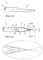
Fig. 11 is a elevational view of a variant of a needle according to the invention, -
Fig. 12 is a view from above of the needle inFig. 11 , -
Fig. 12a is a sectional view of the penetrating tip of the needle inFig. 12 showing a possible cross section, and -
Fig. 12b is a sectional view of the penetrating tip of the needle inFig. 12 showing a variant of the cross section. - In
Figs. 1 and 2 , aneedle 1 for penetrating amembrane 2 is illustrated. Theneedle 1 has apointed end 3 provided with a penetrating tip 4. The outermost portion of the penetrating tip 4 is arranged to lie substantially on thelongitudinal centre line 5 of theneedle 1, i.e. the outermost portion is located on or very close to thecentre line 5. Since the tip 4 is centred relative to theneedle 1, the characteristics of the needle become independent or at least less dependent on how the needle is rotated about itslongitudinal centre line 5 when amembrane 2 is penetrated. In other words, the penetrating tip 4 will impact substantially the same point on the membrane when the membrane is repeatedly penetrated even in the case when the needle is rotated about its longitudinal axis between penetration occasions. This means that the needle will always impact the membrane in the centre of the needle-membrane system resulting in a favourable load distribution on the membrane during penetration thereof, thereby reducing the risk of the membrane cracking adjacent to the penetration hole. Furthermore, in addition to the advantages already described the transport of membrane material into the needle is further obstructed. - Furthermore, the pointed end is provided with an
opening 6 for letting a liquid in and/or out in a main direction 7 which is substantially parallel to the longitudinal extension of theneedle 1. Such a flow direction in the forward direction is an absolute necessity in many medical systems where the needle is included, for avoiding flushing against other adjacent equipment, where otherwise the function of such equipment may be affected by the liquid in an undesirable way. Furthermore, such a flow direction in the forward direction may also enhance mixing of the current drug, such as for example a powdered substance. Although theopening 6 is arranged on substantially one and the same half of the cross section of the needle, and on the upper side of the longitudinal centre line of theneedle 5 such as illustrated inFig. 1 , primarily for reasons associated with the manufacturing of the needle, it would be possible to locate one or more openings in other positions relative to the cross section of theneedle 1, while maintaining the desired main direction of the flow. - The
opening 6, which is located in thepointed end 3 of theneedle 1, is intended to enable a liquid to be transferred to or from theneedle 1. For example, theneedle 1 may be inserted through a membrane which constitutes a seal of a container, such as a medicine bottle, for drawing the contents in the container up and then, in a similar way, the needle may penetrate a second membrane of a second container, such as an infusion bag, for transferring the contents previously drawn up to this second container. - The penetrating tip 4 of the
needle 1 according to the invention is designed with a substantially point-shaped edge 8 to initially prick a membrane when the membrane is penetrated. Furthermore, theouter edges 19 present on thepointed end 3 in the area between the point 8 and aposition 25 beyond theopening 6 are rounded to ensure that, after the initial penetration, thepointed end 3 will push the membrane material away rather than cutting the membrane material when the membrane is penetrated. - In
Fig. 2a an example of a possible cross section of the outermost penetrating tip 4 is illustrated. Although the penetrating tip 4 is illustrated inFig. 2a with a triangular cross section with rounded corners, other symmetries are possible such as a substantially circular cross section. The triangular symmetry gives rise to three substantially equally sized forces affecting the membrane in different directions and radial to the longitudinal extension of the needle. Since the forces counteract each other, the needle will act in a self-centring way during penetration of the membrane. - The
pointed end 3 has suitably a shape substantially corresponding to a part of an imaginary cone, the tip 9 of which coincides with the point 8. By creating a conical shape of the outermost part of thepointed end 3, preferably having a substantially triangular or circular cross section, the desired edge is obtained, which edge has the function to initially prick the membrane and, when penetration continues, thepointed end 3 will push the membrane material away, primarily in directions substantially perpendicular to the longitudinal extension of the needle, instead of cutting the membrane material, such as usual, when the subsequent part of the needle passes through the membrane. This means that, instead of cutting the membrane, the elasticity of the membrane is utilised to enable penetration of the membrane. Thus, the damaging of the membrane by forming a cut, having an extension the size of the diameter of the needle, as being characteristic for prior art needles, is avoided. - To achieve a
pointed end 3 without cutting edges, theneedle 1 may for example be ground and/or blasted and/or electrochemically polished to obtain the desired shape and surface smoothness and to remove possibly burrs located for example around theopening 6. - The invention also relates to an arrangement for transferring a liquid, comprising a
membrane 2 and aneedle 1 according to the invention for penetrating the membrane. The liquid may be transferred from inside the needle to a volume sealed by the membrane or in the opposite direction from the volume to the inside of the needle. - The needle according to the invention may be produced from a stainless steel, such as for example Stainless steel AISI 304, but also other material are possible, such as plastic for instance. With the exception of the
pointed end 3 of the needle, the needle may be designed according to general standards, for example with an outer diameter of approximately 1.2 mm and an inner diameter of approximately 0.9 mm. InFig. 1 , themembrane 2 is also schematically illustrated, which membrane suitably is produced from a thermoplastic elastomer (TPE), though a silicone rubber is also a possible material of the membrane, and which membrane has athickness 10 in the interval from parts of a millimetre to several millimetres, for example up to 10-15 mm or more, and preferably about 3 mm. - It is not unlikely that a
needle 1 according to the invention, which has been designed so that at least in some respects it is blunt as compared to a conventional needle, requires that a larger force be used when the membrane is penetrated. However, this is not particularly critical, since the needle is not intended to penetrate directly in skin and/or tissue of a patient and, thereby, the problem of minimising pain inflicted on the patient to the greatest possible extent is not present. Instead, such as previously described, the primary aim is to minimize the damage of themembrane 2 to the greatest possible extent to thereby avoid possible leakage and contamination when the membrane is penetrated. - In
Fig. 3 , a membrane is depicted which has been penetrated by a needle having a relatively wide cutting edge in accordance with prior art. A number ofcuts 11 have been created when themembrane 2 was penetrated and, furthermore, it is illustrated how apart 12 of themembrane 2 thereby has been cut out and runs the risk of coming loose from the membrane and leading to contamination of the system. - In
Figs. 4 and 4a , a membrane is depicted which has been penetrated by aneedle 1 according to the invention having a substantially point-shaped edge 8. In the example illustrated in 4a, the penetrations have been performed atdifferent locations 13 on themembrane 2. Nevertheless, such as described above, if the point 8 of the penetrating tip 4 is arranged to lie substantially on thelongitudinal centre line 5 of theneedle 1 and the position of thecentre line 5 of the needle relative to the membrane is substantially maintained between the penetrations, penetration may be performed at one and thesame point 13 of the membrane, as illustrated inFig. 4 , even if the needle has been rotated about its own longitudinal axis. In the case illustrated inFig. 4a , however, it is assumed that one or more penetrations have been performed atseveral locations 13 on themembrane 2. - If the point 8 is centred as described above, only one point-shaped
hole 13 of themembrane 2 is formed as a consequence of several penetrations. Ideally, only such a through hole is formed when themembrane 2 is penetrated, but depending on the properties of the membrane, for example thickness, elasticity, etc., the load from the needle may also cause themembrane 2 to crack 14 adjacent to thepenetration hole 13, such as illustrated for some of the penetration positions. However, it should be emphasised that thesecrack formations 14 are not in any way comparable to the cut cuts 11 according toFig. 3 , which necessarily arise when needles according to prior art are used. However, most often thecrack formation 14 which in some cases may arise when the needle according to the invention is used is not desired, and consequently, the characteristics of theneedle 1 and themembrane 2 are suitably adapted to each other so that thesecracks 14 are avoided and/or delimited as regards the size to the greatest possible extent, for example by choosing a membrane material having sufficient elasticity. - In
Figs. 5-10 there is illustrated how aneedle 1 may be manufactured in accordance with the method according to the invention. In a first step illustrated inFig. 5 and 7 , a tubular blank 15 is obliquely cut, which blank 15 preferably has a circular cross section, to obtain apointed end 3. The thus obtained pointedend 3 of the needle has anopening 6 constituting an inlet and/or outlet of a throughchannel 16 in theneedle 1 for transport of fluid. - The
pointed end 3 is then shaped so that the outermost portion of the tip, which tip is intended to constitute a penetrating tip 4 when a membrane is penetrated, lies substantially on thelongitudinal centre line 5 of the tubular blank, i.e. theneedle 1. For this purpose, the tip 4 is bent suitably from aposition 17 located at the periphery of the needle (seeFig. 6 ), where the tip has aposition 17 depicted by dot-dashed lines in a lower part of theneedle 1, in the direction towards (upwards inFig. 6 ) a position in which the tip occupies substantially the centre of a cross section of the needle. A further adjustment of the position of the tip 4 may, if so is desired, be performed in connection with the tip 4 being shaped to the desired shape in for example a subsequent grinding step. - All
outer edges 19 present on the penetrating tip 4 are rounded or chamfered for forming a substantially point-shaped edge 8 according toFigs. 1 and 2 and removing the sharp edges possibly occurring closest to the point 8, which edges otherwise would cut the membrane material when the membrane is penetrated. Suitable methods for removing sharp edges is to blast thepointed end 3 or to use electrochemical polishing. To give the tip 4 a basic shape and/or reduce the need of extensive surface treatment, such as blasting, the tip 4 may first be ground, for example it may be provided with a so-called back bevel cut, and thereafter the required surface treatment in the form of blasting or electrochemical polishing or any similar method is performed. Preferably allsurfaces 18 andedges 19 of thepointed end 3, comprising the penetrating tip 4, in the area between the point 8 and aposition 25 beyond theopening 6, are treated with for example blasting to shape the tip further and remove possibly sharp edges and burrs to give the needle the desired features. Furthermore, advantageously theinner edge 21, at least the rear portion of theinner edge 21 of theopening 6, is also treated with for example blasting. - In
Figs. 8, 9 and 10 , such a back bevel cut mentioned above which may be performed before blasting is illustrated. Furthermore, the needle is illustrated before a possible bending of the tip to the centre line, since it is often easier to grind the tip before bending thereof. The grinding is accomplished primarily on theunderside 20 of thepointed end 3 of theneedle 1 in such a way that, when the needle is seen from above, such as is the case inFig. 9 , a conical shape of the penetrating tip is obtained. Preferably, thepointed end 3 is provided with a first grind angle, i.e. a tip angle α, in the interval 50 to 100°, but theinterval 20 to 50° is also possible, and in many cases the tip angle may be within the interval 30 to 80°. Preferably, thepointed end 3 is further provided with a second grind angle β in the interval 50 to 140°. In the illustrated example, the needle has been ground to the angles α=75° and β=100°, but it should be emphasised that the way of grinding as well as the grinding angles, during the optional grinding step, may be varied in many different ways within the scope of the invention and furthermore that it is the final shape of the needle having a point-shaped edge 8 and a rounded tip 4 without cutting edges that is the basic idea of the invention. Although a back bevel cut is preferably used to give the needle the basic form prior to the rounding of the needle, other grinding operations providing the needle with other cuts such as for example a lancet bevel cut are also possible. - However, it is also possible to obtain the desired angles and/or cross section of the pointed end by a non-cutting process, such as forging, hammering or a similar method. Such a process may be used also to bring the penetrating tip 4 and the point 8 to the desired positions, for example in such a way that the point 8 is situated substantially on the
longitudinal centre line 5 of theneedle 1. Such a process may be used instead of grinding the pointed end or in combination with a grinding operation. After the non-cutting process, allouter edges 19 and/orinner edges 21 present on the pointed end 4 may be rounded for further forming a point 8 and/or removing the sharp edges possibly occurring closest to the point 8 by blasting or electrochemical polishing, as previously described. However, in some cases, the performed non-cutting process itself is sufficient to obtain the requisite dulled edges of the pointed end, at least in the outermost region of the needle, i.e. on the penetrating tip 4. - In
figures 11 and 12 a variant of the needle according to the invention is illustrated. The needle is manufactured from a tubular blank which is obliquely cut to obtain apointed end 3. Preferably, the blank has a circular cross section. The thus obtained pointedend 3 of the needle has anopening 6 constituting an inlet and/or outlet of a throughchannel 16 in theneedle 1 for transport of fluid. Thepointed end 3 is then shaped by for example hammering so that the penetrating tip 4 obtains the desired shape. The thus hammered needle is preferably provided with a basic shape having a tip angle α in theinterval 20° to 100°, and more preferably the tip angle α is in the interval 30° to 80°. Furthermore, the needle may be provided with a basic shape having a rear angle β (corresponding to the second grind angle mentioned above) in the interval 50° to 140° as illustrated inFig. 12b . As an example, the rear angle β may be approximately 100°. Infig. 12a the cross section is substantially circular and thus, there is no rear angel. In other respects the features described in connection with the embodiment illustrated infigures 1 and 2 are applicable to this embodiment too, and same reference numerals denote same or corresponding parts of the needle. - It is emphasised that the needle according to the invention, the arrangement for transferring a liquid according to the invention and the method according to the invention are not limited by the embodiments of the invention described above, but only by the scope of the following claims. Once the idea of the invention is known, several modifications within the scope of the invention could then be obvious to a man skilled in the current technical field.
Claims (32)
- A needle (1) for penetrating a membrane (2), having a pointed end (3) provided with a penetrating tip (4) and with an opening (6) for letting a liquid in and/or out in a main direction (7) which is substantially parallel to the longitudinal extension of the needle, characterized in that the penetrating tip (4) is designed with a point (8) to initially prick a membrane (2) when the membrane is penetrated and that the outer edges (19) present on the pointed end (3) in the area from the point (8) to a position (25) beyond the opening (6) are rounded so that after the initial penetration the pointed end (3) will push the membrane material away rather than cutting the membrane material, whereby said outer edges (19) extend from said point (8).
- A needle according to claim 1, characterized in that the inner edge (21) of the opening (6) is rounded.
- A needle according to claim 1 or 2, characterized in that the penetrating tip (4) is designed with a cross section (26) having a symmetry causing at least three substantially equally sized forces (F) in different directions which are radial to the longitudinal centre line (5) of the needle and which forces counteract each other so that the needle (1) will tend not to deviate from the initial penetration direction when the needle (1) penetrates a membrane (2).
- A needle according to claim 3, characterized in that the cross section is substantially triangular with rounded edges.
- A needle according to claim 3, characterized in that the cross section is substantially circular.
- A needle according to any of claims 1-5, characterized in that the point (8) of the penetrating tip (4) is arranged to lie substantially on the longitudinal centre line (5) of the needle (1).
- A needle according to any of claims 1-6, characterized in that the pointed end (3) has a shape substantially corresponding to a part of an imaginary cone, the tip (9) of which coincides with the point (8).
- A needle according to any of claims 1-7, characterized in that at least a major part of the opening (6) is arranged on one and the same half of the cross section of the needle (1).
- A needle according any of claims 1-8, characterized in that the pointed end (3) is provided with a basic shape in accordance with a lancet bevel cut.
- A needle according any of claims 1-9, characterized in that the pointed end (3) is provided with a basic shape in accordance with a back bevel cut.
- A needle according to claim 10, characterized in that the back bevel cut has a tip angle (α) in the interval 20° to 50°.
- A needle according to claim 10, characterized in that the back bevel cut has a tip angle (α) in the interval 50° to 100°.
- A needle according to claim 10, characterized in that the back bevel cut has a tip angle (α) in the interval 30° to 80°.
- A needle according to claim 12 or 13, characterized in that the tip angle (α) is approximately 75°.
- A needle according any of claims 10-14, characterized in that the back bevel cut has a second grind angle (β) in the interval 50° to 140°.
- A needle according to claim 15, characterized in that the second grind angle (β) is approximately 100°.
- A needle according to any of claims 1-10, characterized in that the needle is provided with a tip angle (α) in the interval 20° to 100°.
- A needle according to claim 17, characterized in that the tip angle (α) is in the interval 30° to 80°.
- A needle according any of claims 1-10, characterized in that the needle is provided with a rear angle (p) in the interval 50° to 140°.
- A needle according to claim 19, characterized in that the rear angle (β) is approximately 100°.
- An arrangement for transferring a liquid, comprising a membrane (2) and a needle (1) according to any of the preceding claims.
- A method for manufacturing a needle (1) for penetrating a membrane (2), comprising:cutting a tubular blank (15) obliquely for obtaining a pointed end (3) provided with a penetrating tip (4) and with a opening (6) for letting a liquid in and/or out in a main direction (7) which is substantially parallel to the longitudinal extension of the needle (1),characterized by providing the penetrating tip (4) with a point (8), androunding all outer edges (19) present on the pointed end (3) and extending from said point (8) in the area from the point (8) to a position (25) beyond the opening (6).
- A method according to claim 22, characterized by rounding the inner edge (21) of the opening (6).
- A method according to claim 22 or 23, characterized by shaping the penetrating tip (4) with a cross section (26) having a symmetry causing at least three substantially equally sized forces (F) in different directions which are radial to the longitudinal centre line (5) of the needle (1) and which forces counteract each other so that the needle (1) will tend not to deviate from the initial penetration direction when the needle (1) penetrates a membrane (2).
- A method according to any of claims 22-24, characterized by arranging the point (8) of the penetrating tip (4) to lie substantially on the longitudinal centre line (5) of the needle (1).
- A method according to any of claims 22-25, characterized by shaping the pointed end (3) as a part of an imaginary cone, the tip (9) of which coincides with the substantially point (8).
- A method according to any of claims 22-26, characterized by shaping the pointed end (3) so that at least a major part of the opening (6) will be located on one and the same half of the cross section of the needle (1).
- A method according to any of claims 22-27, characterized by grinding the penetrating tip (4) in accordance with a lancet bevel cut before rounding the outer edges of the pointed end (3).
- A method according to any of claims 22-28, characterized by grinding the penetrating tip (4) in accordance with a back bevel cut before rounding the outer edges of the pointed end (3).
- A method according to any of claims 22-29, characterized by shaping the penetrating tip (4) by a non-cutting process, such as forging, hammering or similar.
- A method according to any of claims 22-30, characterized by rounding the outer edges (19) by blasting and/or electrochemical polishing.
- A method according to claim 23, characterized by rounding the inner edge (21) of the opening (6) by blasting and/or electrochemical polishing.
Applications Claiming Priority (5)
| Application Number | Priority Date | Filing Date | Title |
|---|---|---|---|
| US44109803P | 2003-01-21 | 2003-01-21 | |
| US441098P | 2003-01-21 | ||
| SE0300155 | 2003-01-21 | ||
| SE0300155A SE526871C2 (en) | 2003-01-21 | 2003-01-21 | Needle for penetrating membrane, includes pointed end with penetrating tip having point-shaped edge to initially prick membrane when the membrane is penetrated |
| PCT/SE2004/000070 WO2004064903A1 (en) | 2003-01-21 | 2004-01-21 | A needle for penetrating a membrane |
Publications (2)
| Publication Number | Publication Date |
|---|---|
| EP1590024A1 EP1590024A1 (en) | 2005-11-02 |
| EP1590024B1 true EP1590024B1 (en) | 2016-04-27 |
Family
ID=32775329
Family Applications (1)
| Application Number | Title | Priority Date | Filing Date |
|---|---|---|---|
| EP04703959.9A Expired - Lifetime EP1590024B1 (en) | 2003-01-21 | 2004-01-21 | A needle for penetrating a membrane |
Country Status (5)
| Country | Link |
|---|---|
| US (1) | US8328772B2 (en) |
| EP (1) | EP1590024B1 (en) |
| JP (1) | JP5148107B2 (en) |
| CA (1) | CA2513705A1 (en) |
| WO (1) | WO2004064903A1 (en) |
Cited By (1)
| Publication number | Priority date | Publication date | Assignee | Title |
|---|---|---|---|---|
| DE102016014445A1 (en) | 2016-07-15 | 2018-01-18 | Acti-Med Ag | Needle for piercing a membrane |
Families Citing this family (71)
| Publication number | Priority date | Publication date | Assignee | Title |
|---|---|---|---|---|
| US8465412B2 (en) | 2001-01-12 | 2013-06-18 | Michael Levy | Uterine devices and method of use |
| US20060183973A1 (en) * | 2001-01-12 | 2006-08-17 | Kamrava Michael M | Endoscopic devices and method of use |
| DE60222735T2 (en) | 2001-01-12 | 2008-07-17 | Napoli, LLC, Beverly Hills | Intrauterine microcatheter |
| US20070202186A1 (en) | 2006-02-22 | 2007-08-30 | Iscience Interventional Corporation | Apparatus and formulations for suprachoroidal drug delivery |
| US8197435B2 (en) | 2006-05-02 | 2012-06-12 | Emory University | Methods and devices for drug delivery to ocular tissue using microneedle |
| JP2008029575A (en) * | 2006-07-28 | 2008-02-14 | Medical Support:Kk | Injection needle for spinal anesthesia and its manufacturing method |
| AU2007335240B2 (en) * | 2006-12-21 | 2011-08-11 | Ssb Technology Pty Ltd | Needle tip |
| US8409140B2 (en) * | 2007-08-17 | 2013-04-02 | Medtronic Minimed, Inc. | Injection apparatus |
| GB0716159D0 (en) * | 2007-08-17 | 2007-09-26 | Precisense As | Injection apparatus |
| US20090082862A1 (en) | 2007-09-24 | 2009-03-26 | Schieber Andrew T | Ocular Implant Architectures |
| US8734377B2 (en) | 2007-09-24 | 2014-05-27 | Ivantis, Inc. | Ocular implants with asymmetric flexibility |
| US20170360609A9 (en) | 2007-09-24 | 2017-12-21 | Ivantis, Inc. | Methods and devices for increasing aqueous humor outflow |
| GB0719037D0 (en) * | 2007-09-28 | 2007-11-07 | Vitrolife Sweden Ab | Sampling needle |
| GB0721778D0 (en) * | 2007-11-06 | 2007-12-19 | Glaxosmithkline Biolog Sa | Novel device |
| US8808222B2 (en) | 2007-11-20 | 2014-08-19 | Ivantis, Inc. | Methods and apparatus for delivering ocular implants into the eye |
| US7766846B2 (en) * | 2008-01-28 | 2010-08-03 | Roche Diagnostics Operations, Inc. | Rapid blood expression and sampling |
| AU2009221859B2 (en) | 2008-03-05 | 2013-04-18 | Alcon Inc. | Methods and apparatus for treating glaucoma |
| US9186128B2 (en) | 2008-10-01 | 2015-11-17 | Covidien Lp | Needle biopsy device |
| US8968210B2 (en) | 2008-10-01 | 2015-03-03 | Covidien LLP | Device for needle biopsy with integrated needle protection |
| US11298113B2 (en) | 2008-10-01 | 2022-04-12 | Covidien Lp | Device for needle biopsy with integrated needle protection |
| US9782565B2 (en) | 2008-10-01 | 2017-10-10 | Covidien Lp | Endoscopic ultrasound-guided biliary access system |
| US9332973B2 (en) | 2008-10-01 | 2016-05-10 | Covidien Lp | Needle biopsy device with exchangeable needle and integrated needle protection |
| EP2451375B1 (en) | 2009-07-09 | 2018-10-03 | Ivantis, Inc. | Single operator device for delivering an ocular implant |
| CN102481404B (en) | 2009-07-09 | 2014-03-05 | 伊万提斯公司 | Ocular implants |
| CN102647960A (en) | 2009-10-23 | 2012-08-22 | 伊万提斯公司 | Ocular implant system and method |
| US9510973B2 (en) | 2010-06-23 | 2016-12-06 | Ivantis, Inc. | Ocular implants deployed in schlemm's canal of the eye |
| CN103327939B (en) | 2010-10-15 | 2017-05-24 | 科尼尔赛德生物医学公司 | Device for ocular access |
| US8657776B2 (en) | 2011-06-14 | 2014-02-25 | Ivantis, Inc. | Ocular implants for delivery into the eye |
| KR20140049594A (en) * | 2011-08-18 | 2014-04-25 | 스펙트라 메디컬 디바이시스, 인크. | Introducer for radiofrequency needle |
| JP6073016B2 (en) * | 2011-11-04 | 2017-02-01 | ニプロ株式会社 | Manufacturing method of injection needle |
| US8663150B2 (en) | 2011-12-19 | 2014-03-04 | Ivantis, Inc. | Delivering ocular implants into the eye |
| WO2013104642A1 (en) * | 2012-01-09 | 2013-07-18 | Fresenius Kabi Deutschland Gmbh | Port cannula for puncturing port catheters |
| US9358156B2 (en) | 2012-04-18 | 2016-06-07 | Invantis, Inc. | Ocular implants for delivery into an anterior chamber of the eye |
| ES2734977T3 (en) * | 2012-09-24 | 2019-12-13 | Siemens Healthcare Diagnostics Products Gmbh | Hollow needle for a sample pipette |
| KR20150083117A (en) | 2012-11-08 | 2015-07-16 | 클리어사이드 바이오메디컬, 인코포레이드 | Methods and devices for the treatment of ocular disease in human subjects |
| US10617558B2 (en) | 2012-11-28 | 2020-04-14 | Ivantis, Inc. | Apparatus for delivering ocular implants into an anterior chamber of the eye |
| EP2938375B1 (en) * | 2012-12-31 | 2019-05-01 | Hospira, Inc. | Cartridge assembly for an injection system |
| US20140276051A1 (en) | 2013-03-13 | 2014-09-18 | Gyrus ACM, Inc. (d.b.a Olympus Surgical Technologies America) | Device for Minimally Invasive Delivery of Treatment Substance |
| CN110302004B (en) | 2013-05-03 | 2023-04-28 | 科尼尔赛德生物医学公司 | Apparatus and method for ocular injection |
| WO2014197317A1 (en) | 2013-06-03 | 2014-12-11 | Clearside Biomedical, Inc. | Apparatus and methods for drug delivery using multiple reservoirs |
| US20150027241A1 (en) * | 2013-07-23 | 2015-01-29 | Diba Industries, Inc. | Piercing probes with offset conical piercing tip and fluid-sampling systems comprising the piercing probes |
| US20160207229A1 (en) * | 2013-09-04 | 2016-07-21 | Ube Industries, Ltd. | Film retainer and tenter apparatus |
| US10123818B2 (en) * | 2014-01-13 | 2018-11-13 | Heather Lee Alvarez | Buttonhole tool |
| CN105939740B (en) * | 2014-01-31 | 2019-11-01 | 泰尔茂株式会社 | The manufacturing method of therapeutic medical puncture needle and puncture needle |
| KR101537185B1 (en) * | 2014-02-17 | 2015-07-15 | 김경균 | Medicial injection syringe and |
| MX2016017028A (en) | 2014-06-20 | 2017-08-07 | Clearside Biomedical Inc | Variable diameter cannula and methods for controlling insertion depth for medicament delivery. |
| FR3023189B1 (en) * | 2014-07-04 | 2021-03-26 | Aptar France Sas | FLUID PRODUCT DISTRIBUTION DEVICE. |
| US10709547B2 (en) | 2014-07-14 | 2020-07-14 | Ivantis, Inc. | Ocular implant delivery system and method |
| US10182798B2 (en) | 2014-07-30 | 2019-01-22 | Covidien Lp | Exchangeable core biopsy needle |
| US10159470B2 (en) | 2014-07-30 | 2018-12-25 | Covidien Lp | Exchangeable core biopsy needle |
| USD750223S1 (en) | 2014-10-14 | 2016-02-23 | Clearside Biomedical, Inc. | Medical injector for ocular injection |
| DE102014116287A1 (en) * | 2014-11-07 | 2016-05-12 | Rena Gmbh | Method and device for producing cannulas |
| WO2016094620A1 (en) * | 2014-12-11 | 2016-06-16 | Facet Technologies, Llc | Needle with multi-bevel tip geometry |
| FR3029810B1 (en) * | 2014-12-16 | 2019-06-07 | Aptar France Sas | DEVICE FOR DISPENSING FLUID PRODUCT. |
| US9844362B2 (en) | 2015-01-13 | 2017-12-19 | Covidien Lp | Exchangeable core biopsy needle |
| EP3297708B1 (en) * | 2015-05-22 | 2022-02-23 | DexCom, Inc. | Needle for transcutaneous analyte sensor delivery |
| WO2016195132A1 (en) * | 2015-06-03 | 2016-12-08 | (주)리젠바이오참 | Medical injection needle and manufacturing method therefor |
| JP6837475B2 (en) | 2015-08-14 | 2021-03-03 | イバンティス インコーポレイテッド | Ocular implant and delivery system with pressure sensor |
| JP2018532513A (en) * | 2015-11-04 | 2018-11-08 | カスタム メディカル アプリケーションズ インコーポレーティッド | Needle and related assemblies and methods |
| WO2017106517A1 (en) | 2015-12-15 | 2017-06-22 | Ivantis, Inc. | Ocular implant and delivery system |
| US20170224376A1 (en) * | 2016-02-08 | 2017-08-10 | Injectimed, Inc. | Echogenic needles and methods for manufacturing echogenic needles |
| EP3413851B1 (en) | 2016-02-10 | 2023-09-27 | Clearside Biomedical, Inc. | Packaging |
| CA3062845A1 (en) | 2016-05-02 | 2017-11-09 | Clearside Biomedical, Inc. | Systems and methods for ocular drug delivery |
| US10973681B2 (en) | 2016-08-12 | 2021-04-13 | Clearside Biomedical, Inc. | Devices and methods for adjusting the insertion depth of a needle for medicament delivery |
| JP7337046B2 (en) * | 2017-08-04 | 2023-09-01 | ベクトン・ディキンソン・アンド・カンパニー | needle and catheterization devices |
| USD1023297S1 (en) * | 2018-06-04 | 2024-04-16 | Airlift Concrete Experts, LLC | Subterranean injection rod tip |
| US20220087864A1 (en) * | 2019-01-14 | 2022-03-24 | Raico International, Llc | Surgical instrument for goniotomy procedure, method of use, and method of manufacture |
| US20210000648A1 (en) * | 2019-07-03 | 2021-01-07 | Raico International, Llc | Surgical instrument and method for goniotomy procedure |
| CN110354334A (en) * | 2019-07-24 | 2019-10-22 | 河南曙光汇知康生物科技股份有限公司 | Transfusion port puncture needle head and its manufactured transfusion port puncture needle |
| WO2022120269A1 (en) * | 2020-12-04 | 2022-06-09 | Koska Family Limited | Systems and methods for rotational piercing of pre-filled medical delivery assemblies |
| AU2022205382A1 (en) | 2021-01-11 | 2023-06-22 | Alcon Inc. | Systems and methods for viscoelastic delivery |
Family Cites Families (204)
| Publication number | Priority date | Publication date | Assignee | Title |
|---|---|---|---|---|
| US1844342A (en) * | 1930-04-21 | 1932-02-09 | Berman Phoebus | Bottle nozzle |
| US2010417A (en) | 1933-11-17 | 1935-08-06 | Martin C Schwab | Liquid flow apparatus |
| US2717599A (en) * | 1952-02-18 | 1955-09-13 | Huber Jennie | Needle structure |
| US2697438A (en) * | 1953-10-16 | 1954-12-21 | Bishop & Co Platinum Works J | Noncoring hypodermic needle |
| US3064651A (en) * | 1959-05-26 | 1962-11-20 | Henderson Edward | Hypodermic needle |
| US3071135A (en) * | 1960-01-27 | 1963-01-01 | Mfg Process Lab Inc | Hollow needle |
| US3308822A (en) * | 1964-04-02 | 1967-03-14 | Loretta Fontano | Hypodermic needle |
| US3316908A (en) * | 1964-04-14 | 1967-05-02 | Burron Medical Prod Inc | Intravenous injection apparatus |
| FR1418064A (en) * | 1964-07-10 | 1965-11-19 | Advanced device for infusion and blood transfusion | |
| US3340671A (en) | 1964-08-10 | 1967-09-12 | Carnation Co | Method of filling containers under aseptic conditions |
| US3448740A (en) * | 1966-06-24 | 1969-06-10 | Frank H J Figge | Nonheel shaving hypodermic needle |
| US3542240A (en) | 1968-10-14 | 1970-11-24 | Ida Solowey | Partially assembled bulk parenteral solution container and adminstration set |
| DE2005519A1 (en) | 1970-02-06 | 1971-10-28 | Roescheisen & Co Süddeutsche Bindenfabrik, 7900 Ulm | Hypodermic syringe needle |
| US3783895A (en) * | 1971-05-04 | 1974-01-08 | Sherwood Medical Ind Inc | Universal parenteral fluid administration connector |
| US3788320A (en) * | 1972-02-25 | 1974-01-29 | Kendall & Co | Spinal needle |
| JPS4912690A (en) * | 1972-05-17 | 1974-02-04 | ||
| US3822700A (en) * | 1973-03-16 | 1974-07-09 | M Pennington | Intravenous solution dispenser |
| US3976073A (en) | 1974-05-01 | 1976-08-24 | Baxter Laboratories, Inc. | Vial and syringe connector assembly |
| US3938520A (en) * | 1974-06-10 | 1976-02-17 | Abbott Laboratories | Transfer unit having a dual channel transfer member |
| US4096860A (en) * | 1975-10-08 | 1978-06-27 | Mclaughlin William F | Dual flow encatheter |
| DK164487C (en) | 1976-03-22 | 1992-11-23 | Haustrup Plastic As | CONTAINER FOR STERILE STORAGE OF FLUID, SUCH AS INFUSING OR RINSE FLUID |
| JPS5460986U (en) * | 1977-10-07 | 1979-04-27 | ||
| US4296786A (en) | 1979-09-28 | 1981-10-27 | The West Company | Transfer device for use in mixing a primary solution and a secondary or additive substance |
| USD270568S (en) | 1980-07-01 | 1983-09-13 | Armstrong Lee C | Adapter for making connection into a container through a pierceable top |
| US4516967A (en) * | 1981-12-21 | 1985-05-14 | Kopfer Rudolph J | Wet-dry compartmental syringe |
| SE456637B (en) * | 1982-04-13 | 1988-10-24 | Gambro Lundia Ab | HEATER RELIABLE CLUTCH |
| JPS5927389A (en) * | 1982-08-02 | 1984-02-13 | ザ・コカ−コ−ラ・カンパニ− | Method of conveying and cooking condensed syrup and mount used therefor |
| US5199947A (en) * | 1983-01-24 | 1993-04-06 | Icu Medical, Inc. | Method of locking an influent line to a piggyback connector |
| US4490139A (en) * | 1983-01-28 | 1984-12-25 | Eli Lilly And Company | Implant needle and method |
| SE434700B (en) * | 1983-05-20 | 1984-08-13 | Bengt Gustavsson | DEVICE FOR AIRED TRANSFER OF SUBSTANCE FROM A KERLE TO ANOTHER |
| EP0123659A1 (en) | 1983-03-21 | 1984-10-31 | Jan Ingemar Näslund | An arrangement in apparatus for preparing solutions from harmful substances |
| EP0165926B1 (en) * | 1983-05-20 | 1990-10-24 | Bengt Gustavsson | A device for transferring a substance |
| US4632673A (en) | 1983-06-15 | 1986-12-30 | Hantaaki Oy | Pierceable port for containers |
| US4573967A (en) * | 1983-12-06 | 1986-03-04 | Eli Lilly And Company | Vacuum vial infusion system |
| JPS60129941U (en) | 1984-02-09 | 1985-08-31 | テルモ株式会社 | medical equipment |
| IT1173370B (en) * | 1984-02-24 | 1987-06-24 | Erba Farmitalia | SAFETY DEVICE TO CONNECT A SYRINGE TO THE MOUTH OF A BOTTLE CONTAINING A DRUG OR A TUBE FOR DISPENSING THE SYRINGE DRUG |
| US4581016A (en) * | 1984-02-29 | 1986-04-08 | Gettig Pharmaceutical Instrument Co. | Dual cartridge wet/dry syringe |
| US4623343A (en) | 1984-03-19 | 1986-11-18 | Quest Medical, Inc. | Parenteral fluid administration apparatus and method |
| US4588403A (en) * | 1984-06-01 | 1986-05-13 | American Hospital Supply Corporation | Vented syringe adapter assembly |
| US4759756A (en) | 1984-09-14 | 1988-07-26 | Baxter Travenol Laboratories, Inc. | Reconstitution device |
| EP0201611A1 (en) * | 1985-05-10 | 1986-11-20 | B. Braun-SSC AG | Two cannulae syringe |
| DE3687530T2 (en) | 1985-06-27 | 1993-07-22 | Duphar Int Res | SYRINGE. |
| ES2017924B3 (en) * | 1985-10-11 | 1991-03-16 | Duphar Int Res B V | AUTOMATIC INJECTOR. |
| US4808170A (en) * | 1985-12-16 | 1989-02-28 | Alcon Laboratories, Inc. | Hypotraumatic injection needle useful in ophthalmic surgery |
| SE451089B (en) * | 1985-12-20 | 1987-08-31 | Steridose Systems Ab | CONTAMINATION-FREE CLUTCH |
| DE3600496A1 (en) * | 1986-01-10 | 1987-07-16 | Josef Magasi | TUNING CANNULES, THEIR HANDLE AND METHOD FOR THE PRODUCTION THEREOF |
| US4673400A (en) * | 1986-02-10 | 1987-06-16 | Martin Ivan W | Aseptic connector assembly for conduits for sterile fluids |
| US4878897A (en) | 1986-05-15 | 1989-11-07 | Ideation Enterprises, Inc. | Injection site device having a safety shield |
| IT207945Z2 (en) | 1986-07-25 | 1988-03-14 | Farmitaglia Carlo Erba S P A | DEVICE FOR THE CONNECTION OF A TUBE TO AN APPARATUS SUITABLE FOR COUPLING A SYRINGE TO A BOTTLE CONTAINING A DRUG. |
| IT207944Z2 (en) | 1986-07-25 | 1988-03-14 | Erba Farmitalia | LOCKING DEVICE OF A SYRINGE ON A BODY TO WHICH THE SYRINGE MUST BE COUPLED. |
| DE3772773D1 (en) * | 1986-11-06 | 1991-10-10 | Bengt Gustavsson | CONTAINER FOR STORAGE OR COLLECTION OF LIQUIDS AND DRY SUBSTANCES. |
| US4864717A (en) | 1986-11-20 | 1989-09-12 | American Magnetics Corporation | Method of making a digital magnetic head structure |
| DE3643235C1 (en) * | 1986-12-18 | 1987-11-12 | Braun Melsungen Ag | Steel cannulas for spinal and peridural anesthesia |
| US4752287A (en) * | 1986-12-30 | 1988-06-21 | Bioresearch, Inc. | Syringe check valve |
| US5041105A (en) | 1987-03-03 | 1991-08-20 | Sherwood Medical Company | Vented spike connection component |
| IE62230B1 (en) | 1987-04-02 | 1995-01-11 | Drg Uk Ltd | Apparatus for contacting material such as a drug with a fluid |
| CH686778A5 (en) * | 1987-05-29 | 1996-06-28 | Vifor Medical Ag | Container for separate storage of active compounds and their subsequent mixing. |
| US4768568A (en) | 1987-07-07 | 1988-09-06 | Survival Technology, Inc. | Hazardous material vial apparatus providing expansible sealed and filter vented chambers |
| ES2050000T3 (en) * | 1987-07-10 | 1994-05-01 | Braun Melsungen Ag | CANNULA. |
| IT211830Z2 (en) * | 1987-09-22 | 1989-05-25 | Farmitalia Carl Erba S P A | SAFETY DEVICE FOR THE INTRODUCTION AND WITHDRAWAL OF LIQUIDS IN AND FROM DRUG BOTTLES AND SIMILAR. |
| US4834717A (en) * | 1987-09-25 | 1989-05-30 | Habley Medical Technology Corporation | Disposable, pre-sterilizable syringe for a pre-filled medication cartridge |
| IT1231892B (en) | 1987-10-14 | 1992-01-15 | Farmitalia Carlo Erba S P A Mi | APPARATUS WITH SAFETY LOCKING ORGANS FOR CONNECTION OF A SYRINGE TO A BOTTLE CONTAINING A DRUG |
| US4850978A (en) | 1987-10-29 | 1989-07-25 | Baxter International Inc. | Drug delivery cartridge with protective cover |
| CA1335167C (en) | 1988-01-25 | 1995-04-11 | Steven C. Jepson | Pre-slit injection site and associated cannula |
| US5176673A (en) * | 1988-06-02 | 1993-01-05 | Piero Marrucchi | Method and device for manipulating and transferring products between confined volumes |
| US5514117A (en) * | 1988-09-06 | 1996-05-07 | Lynn; Lawrence A. | Connector having a medical cannula |
| US4994048A (en) * | 1988-09-19 | 1991-02-19 | Becton, Dickinson And Company | Apparatus and method for connecting a passageway and openings with a connector |
| US4898209A (en) * | 1988-09-27 | 1990-02-06 | Baxter International Inc. | Sliding reconstitution device with seal |
| CA2001732A1 (en) | 1988-10-31 | 1990-04-30 | Lawrence A. Lynn | Intravenous line coupling device |
| US4997429A (en) | 1988-12-28 | 1991-03-05 | Sherwood Medical Company | Enteral bottle cap with vent valve |
| US4964855A (en) | 1989-03-31 | 1990-10-23 | Joseph J. Todd | Connector with recessed needle for Y-tube, and assembly |
| ES2050441T3 (en) * | 1989-05-03 | 1994-05-16 | Baxter Int | FRANGIBLE TIP CONNECTOR FOR SOLUTION BAG. |
| US4944736A (en) | 1989-07-05 | 1990-07-31 | Holtz Leonard J | Adaptor cap for centering, sealing, and holding a syringe to a bottle |
| US5017186A (en) * | 1989-07-11 | 1991-05-21 | Arnold Victor A | Device and method for maintaining sterility of multi-dose medicament vials |
| JPH0330963U (en) * | 1989-08-04 | 1991-03-26 | ||
| US4982769A (en) * | 1990-02-21 | 1991-01-08 | Survival Technology, Inc. | Package |
| US5122116A (en) * | 1990-04-24 | 1992-06-16 | Science Incorporated | Closed drug delivery system |
| US5071413A (en) | 1990-06-13 | 1991-12-10 | Utterberg David S | Universal connector |
| US5515871A (en) * | 1990-09-28 | 1996-05-14 | Sulzer Brothers Ltd. | Hollow needle for medical use and a laser method for manufacturing |
| US5122123A (en) * | 1991-01-30 | 1992-06-16 | Vaillancourt Vincent L | Closed system connector assembly |
| SE9101102D0 (en) | 1991-04-11 | 1991-04-11 | Viggo Spectramed Ab | NEEDLE PROTECTION DEVICE |
| JP3030963B2 (en) | 1991-08-23 | 2000-04-10 | 日本電気株式会社 | Method for manufacturing semiconductor device |
| US5308347A (en) * | 1991-09-18 | 1994-05-03 | Fujisawa Pharmaceutical Co., Ltd. | Transfusion device |
| US5201725A (en) * | 1991-09-26 | 1993-04-13 | Ivac | Needle free i.v. adapter |
| US5207658A (en) * | 1991-11-14 | 1993-05-04 | Rosen Howard J | Prick resistant medical needle for intravenous injections |
| NZ334983A (en) | 1991-12-18 | 2001-03-30 | Icu Medical Inc | Medical valve with a resilient seal |
| US5254097A (en) | 1992-01-06 | 1993-10-19 | Datascope Investment Corp. | Combined percutaneous cardiopulmonary bypass (PBY) and intra-aortic balloon (IAB) access cannula |
| JP2605345Y2 (en) | 1992-05-01 | 2000-07-10 | 株式会社大塚製薬工場 | Drug container |
| US5478328A (en) | 1992-05-22 | 1995-12-26 | Silverman; David G. | Methods of minimizing disease transmission by used hypodermic needles, and hypodermic needles adapted for carrying out the method |
| US5279576A (en) * | 1992-05-26 | 1994-01-18 | George Loo | Medication vial adapter |
| US5232109A (en) | 1992-06-02 | 1993-08-03 | Sterling Winthrop Inc. | Double-seal stopper for parenteral bottle |
| US5385545A (en) * | 1992-06-24 | 1995-01-31 | Science Incorporated | Mixing and delivery system |
| US5352215A (en) | 1992-08-26 | 1994-10-04 | Scimed Life Systems, Inc. | Y-adapter with a sideport radius |
| US5279583A (en) * | 1992-08-28 | 1994-01-18 | Shober Jr Robert C | Retractable injection needle assembly |
| US5334163A (en) | 1992-09-16 | 1994-08-02 | Sinnett Kevin B | Apparatus for preparing and administering a dose of a fluid mixture for injection into body tissue |
| US5603706A (en) * | 1992-09-29 | 1997-02-18 | Wyatt; Philip | Infusion apparatus |
| US5328480A (en) | 1992-10-09 | 1994-07-12 | Cook Incorporated | Vascular wire guiode introducer and method of use |
| US5290254A (en) * | 1992-11-16 | 1994-03-01 | Vaillancourt Vincent L | Shielded cannula assembly |
| US5385547A (en) * | 1992-11-19 | 1995-01-31 | Baxter International Inc. | Adaptor for drug delivery |
| US5356406A (en) | 1993-01-08 | 1994-10-18 | Steven Schraga | Adaptor to facilitate interconnection of medicine bottle and syringe |
| US5766211A (en) * | 1993-02-08 | 1998-06-16 | Wood; Jan | Medical device for allowing insertion and drainage into a body cavity |
| US5389085A (en) * | 1993-02-11 | 1995-02-14 | International Medical Consultants, Inc. | Automatic needle protector |
| US5984899A (en) | 1993-02-11 | 1999-11-16 | Beech Medical Products, Inc. | Needle protector device having a lockable protective cover which is unlockable during actuation |
| US5795336A (en) | 1993-02-11 | 1998-08-18 | Beech Medical Products, Inc. | Automatic needle protector having features for facilitating assembly |
| DE4311715C2 (en) * | 1993-04-08 | 1996-02-01 | Fresenius Ag | Port cannula |
| US5817083A (en) | 1993-05-31 | 1998-10-06 | Migda Inc. | Mixing device and clamps useful therein |
| US5593028A (en) * | 1993-07-02 | 1997-01-14 | Habley Medical Technology Corporation | Multi-pharmaceutical storage, mixing and dispensing vial |
| US5445630A (en) | 1993-07-28 | 1995-08-29 | Richmond; Frank M. | Spike with luer fitting |
| US5405326A (en) * | 1993-08-26 | 1995-04-11 | Habley Medical Technology Corporation | Disposable safety syringe with retractable shuttle for luer lock needle |
| US6146362A (en) | 1993-08-27 | 2000-11-14 | Baton Development, Inc. | Needleless IV medical delivery system |
| WO1995007066A1 (en) | 1993-09-07 | 1995-03-16 | Debiotech S.A. | Syringe device for mixing two compounds |
| US5492531A (en) * | 1993-09-08 | 1996-02-20 | Ethox Corporation | Infuser apparatus for the gastric cavity |
| US5837262A (en) | 1994-07-27 | 1998-11-17 | Bio-Virus Research Incorporated | Pharmaceutical compositions against several herpes virus infections and/or atherosclerotic plaque |
| US5613954A (en) * | 1994-11-21 | 1997-03-25 | Stryker Corporation | Laparoscopic surgical Y-tube cannula |
| US5647845A (en) | 1995-02-01 | 1997-07-15 | Habley Medical Technology Corporation | Generic intravenous infusion system |
| DE19506163C2 (en) | 1995-02-22 | 1998-01-29 | Hans Mueller | Blood treatment device |
| IL114960A0 (en) * | 1995-03-20 | 1995-12-08 | Medimop Medical Projects Ltd | Flow control device |
| US5575780A (en) * | 1995-04-28 | 1996-11-19 | Saito; Yoshikuni | Medical hollow needle and a method of producing thereof |
| US5820609A (en) * | 1995-04-28 | 1998-10-13 | Saito; Yoshikuni | Medical hollow needle and a method of producing thereof |
| SE509950C2 (en) | 1995-05-02 | 1999-03-29 | Carmel Pharma Ab | Device for the administration of toxic liquid |
| US5839715A (en) | 1995-05-16 | 1998-11-24 | Alaris Medical Systems, Inc. | Medical adapter having needleless valve and sharpened cannula |
| US5766147A (en) * | 1995-06-07 | 1998-06-16 | Winfield Medical | Vial adaptor for a liquid delivery device |
| FR2735357B1 (en) * | 1995-06-14 | 1997-12-05 | Py Daniel C | DOUBLE EYE INSTILLATOR |
| US5536259A (en) * | 1995-07-28 | 1996-07-16 | Medisystems Technology Corp | Hypodermic cannula |
| FR2738550B1 (en) * | 1995-09-11 | 1997-11-07 | Biodome | DEVICE FOR SEALING A CONTAINER ITSELF CLOSED, ASSEMBLY FOR PROVIDING A PRODUCT COMPRISING SUCH A CONTAINER AND SUCH A SEALING DEVICE |
| DE29607437U1 (en) | 1996-04-24 | 1997-08-21 | Braun Melsungen Ag | Medical device |
| DK1015382T3 (en) | 1996-06-07 | 2010-03-08 | Mark L Anderson | Fluid dispenser |
| US5752942A (en) * | 1996-06-20 | 1998-05-19 | Becton Dickinson And Company | Five beveled point geometry for a hypodermic needle |
| US5897526A (en) * | 1996-06-26 | 1999-04-27 | Vaillancourt; Vincent L. | Closed system medication administering system |
| FR2753624B1 (en) * | 1996-09-25 | 1999-04-16 | Biodome | CONNECTION DEVICE, PARTICULARLY BETWEEN A CONTAINER WITH PERFORABLE CAP AND A SYRINGE |
| SE9604162D0 (en) * | 1996-11-13 | 1996-11-13 | Astra Ab | membrane |
| FR2757405B1 (en) | 1996-12-23 | 1999-08-06 | Vermed | NON-CORE SEPTUM CROSSING NEEDLE |
| GB9701413D0 (en) | 1997-01-24 | 1997-03-12 | Smithkline Beecham Biolog | Novel device |
| JPH11128347A (en) * | 1997-11-03 | 1999-05-18 | Jun Taiko | Injector needle without generating chip |
| US6159192A (en) | 1997-12-04 | 2000-12-12 | Fowles; Thomas A. | Sliding reconstitution device with seal |
| US6221065B1 (en) * | 1998-04-03 | 2001-04-24 | Filtertek Inc. | Self-priming needle-free “Y”-adapter |
| US6209738B1 (en) * | 1998-04-20 | 2001-04-03 | Becton, Dickinson And Company | Transfer set for vials and medical containers |
| WO1999058176A1 (en) * | 1998-05-08 | 1999-11-18 | Dr. Japan Co. Ltd. | Medical puncture needle and method of manufacturing same |
| FR2780878B1 (en) | 1998-07-10 | 2000-09-29 | Frederic Senaux | SNAP-ON TRANSFER CAP |
| JP2000074928A (en) * | 1998-08-31 | 2000-03-14 | Sysmex Corp | Liquid suction pipe |
| US7425209B2 (en) | 1998-09-15 | 2008-09-16 | Baxter International Inc. | Sliding reconstitution device for a diluent container |
| US6113583A (en) | 1998-09-15 | 2000-09-05 | Baxter International Inc. | Vial connecting device for a sliding reconstitution device for a diluent container |
| FR2783808B1 (en) * | 1998-09-24 | 2000-12-08 | Biodome | CONNECTION DEVICE BETWEEN A CONTAINER AND A CONTAINER AND READY-TO-USE ASSEMBLY COMPRISING SUCH A DEVICE |
| US6113068A (en) | 1998-10-05 | 2000-09-05 | Rymed Technologies | Swabbable needleless injection port system having low reflux |
| JP2000167022A (en) | 1998-12-04 | 2000-06-20 | Showa Denko Kk | Double-room medical container |
| USD427308S (en) * | 1999-01-22 | 2000-06-27 | Medimop Medical Projects Ltd. | Vial adapter |
| US6245056B1 (en) * | 1999-02-12 | 2001-06-12 | Jack M. Walker | Safe intravenous infusion port injectors |
| US6331176B1 (en) | 1999-03-11 | 2001-12-18 | Advanced Cardiovascular Systems, Inc. | Bleed back control assembly and method |
| JP3492543B2 (en) * | 1999-03-15 | 2004-02-03 | 金子工業有限会社 | Injection needle and its manufacturing method |
| DE19927356C2 (en) | 1999-06-16 | 2001-09-27 | Fresenius Ag | Extendable connector assembly with a connection system and a port system for connecting a hose and a medical container |
| US6644367B1 (en) | 1999-07-23 | 2003-11-11 | Scholle Corporation | Connector assembly for fluid flow with rotary motion for connection and disconnection |
| US6253804B1 (en) | 1999-11-05 | 2001-07-03 | Minimed Inc. | Needle safe transfer guard |
| FR2800713B1 (en) | 1999-11-05 | 2002-01-04 | Biodome | CONNECTION DEVICE BETWEEN A CONTAINER AND A CONTAINER AND READY-TO-USE ASSEMBLY COMPRISING SUCH A DEVICE |
| US6453956B2 (en) | 1999-11-05 | 2002-09-24 | Medtronic Minimed, Inc. | Needle safe transfer guard |
| USD445501S1 (en) | 2000-01-24 | 2001-07-24 | Bracco Diagnostics, Inc. | Vial access adapter |
| DE10009816A1 (en) | 2000-03-01 | 2001-10-18 | Disetronic Licensing Ag | Needle protection device for an injection device |
| JP2001293085A (en) * | 2000-04-11 | 2001-10-23 | Nipro Corp | Indwelling needle for dialysis |
| US6471674B1 (en) | 2000-04-21 | 2002-10-29 | Medrad, Inc. | Fluid delivery systems, injector systems and methods of fluid delivery |
| AU2001266248A1 (en) * | 2000-06-21 | 2002-01-02 | Paul Francois Roos | Self closing coupling |
| SE517084C2 (en) | 2000-08-10 | 2002-04-09 | Carmel Pharma Ab | Procedures and devices for aseptic preparation |
| CA2426182C (en) * | 2000-10-23 | 2007-03-13 | Py Patent, Inc. | Fluid dispenser having a housing and flexible inner bladder |
| US6595964B2 (en) * | 2000-12-22 | 2003-07-22 | Baxter International Inc. | Luer activated thread coupler |
| US6656433B2 (en) | 2001-03-07 | 2003-12-02 | Churchill Medical Systems, Inc. | Vial access device for use with various size drug vials |
| US6685692B2 (en) * | 2001-03-08 | 2004-02-03 | Abbott Laboratories | Drug delivery system |
| US7470258B2 (en) | 2001-03-13 | 2008-12-30 | Mdc Investment Holdings, Inc. | Pre-filled safety vial injector |
| EP1449555B1 (en) * | 2001-03-23 | 2006-06-21 | Novo Nordisk A/S | Needle cannula |
| US20030010717A1 (en) * | 2001-07-13 | 2003-01-16 | Nx Stage Medical, Inc. | Systems and methods for handling air and/or flushing fluids in a fluid circuit |
| US6715520B2 (en) * | 2001-10-11 | 2004-04-06 | Carmel Pharma Ab | Method and assembly for fluid transfer |
| JP2003265608A (en) | 2002-03-14 | 2003-09-24 | Terumo Corp | Collecting tool |
| US7744581B2 (en) * | 2002-04-08 | 2010-06-29 | Carmel Pharma Ab | Device and method for mixing medical fluids |
| US6994699B2 (en) | 2002-06-12 | 2006-02-07 | Baxter International Inc. | Port, a container and a method for accessing a port |
| CA2495905C (en) | 2002-08-22 | 2007-05-08 | Glenn G. Fournie | Sliding seal adapter for a feeding system |
| DE10247965A1 (en) * | 2002-10-15 | 2004-05-06 | Transcoject Gesellschaft für medizinische Geräte mbH & Co KG | Tamper-evident closure for a syringe |
| BR0315842A (en) * | 2002-10-29 | 2005-09-27 | Vasogen Ireland Ltd | Device and method for controlled gas expression of medical fluid delivery systems |
| CA103134S (en) * | 2002-11-26 | 2004-08-11 | Nipro Corp | Adapter for transfer of medical solution |
| US6786244B1 (en) | 2003-03-31 | 2004-09-07 | International Business Machines Corporation | Apparatus and method to enhance reservoir utilization in a medical infusion device |
| USD495416S1 (en) | 2003-05-30 | 2004-08-31 | Alaris Medical Systems, Inc. | Vial access device |
| FR2861310B1 (en) | 2003-10-22 | 2006-09-22 | Plastef Investissements | SECURE INJECTION SYRINGE DEVICE |
| FR2867396B1 (en) | 2004-03-10 | 2006-12-22 | P2A | PERFORATING PERFORMER WITH STERILE CONNECTION |
| US7645268B2 (en) * | 2004-03-25 | 2010-01-12 | Boston Scientific Scimed, Inc. | Needles and methods of using same |
| US7615041B2 (en) * | 2004-07-29 | 2009-11-10 | Boston Scientific Scimed, Inc. | Vial adaptor |
| FR2874505B1 (en) | 2004-08-27 | 2007-06-08 | Sedat Sa | INJECTION DEVICE COMPRISING A SYRINGE |
| US7192423B2 (en) * | 2004-11-17 | 2007-03-20 | Cindy Wong | Dispensing spike assembly with removable indicia bands |
| EP1853333A1 (en) * | 2004-12-23 | 2007-11-14 | Bracco Research S.A. | Liquid transfer device for medical dispensing containers |
| GB0500366D0 (en) * | 2005-01-08 | 2005-02-16 | Liversidge Barry P | Medical needle safety devices |
| US7347458B2 (en) | 2005-01-14 | 2008-03-25 | C. R. Bard, Inc. | Locking luer fitting |
| US7935070B2 (en) | 2005-01-28 | 2011-05-03 | Fresenius Medical Care North America | Systems and methods for dextrose containing peritoneal dialysis (PD) solutions with neutral pH and reduced glucose degradation product |
| ITMO20050141A1 (en) | 2005-06-09 | 2006-12-10 | Aries S R L | CLOSING DEVICE FOR CONTAINERS OR LINES OF ADMINISTRATION OF MEDICINAL OR FERMACEUTICAL FLUIDS. |
| FR2887153B1 (en) * | 2005-06-20 | 2008-04-04 | Alain Villette | INJECTION NEEDLE |
| US7998134B2 (en) | 2007-05-16 | 2011-08-16 | Icu Medical, Inc. | Medical connector |
| US7322941B2 (en) * | 2005-09-13 | 2008-01-29 | Modalworks Inc. | Arterial syringe safety vent |
| PL1951344T3 (en) * | 2005-11-07 | 2015-02-27 | Borla Ind | Vented safe handling vial adapter |
| US7547300B2 (en) * | 2006-04-12 | 2009-06-16 | Icu Medical, Inc. | Vial adaptor for regulating pressure |
| US7703486B2 (en) * | 2006-06-06 | 2010-04-27 | Cardinal Health 414, Inc. | Method and apparatus for the handling of a radiopharmaceutical fluid |
| EP2054008B1 (en) | 2006-08-18 | 2012-01-11 | Medingo Ltd. | Methods and devices for delivering fluid to a reservoir of a fluid delivery device |
| DE102006042233B3 (en) | 2006-09-06 | 2008-03-06 | Tecpharma Licensing Ag | Needle guard with distal and proximal needle guard |
| US7857805B2 (en) | 2006-10-02 | 2010-12-28 | B. Braun Medical Inc. | Ratcheting luer lock connector |
| ATE422937T1 (en) * | 2006-10-31 | 2009-03-15 | Codan Holding Gmbh | NON-RECONNECTABLE POSITIVE LUER-LOCK CONNECTOR |
| US7942860B2 (en) | 2007-03-16 | 2011-05-17 | Carmel Pharma Ab | Piercing member protection device |
| USD570477S1 (en) * | 2007-03-23 | 2008-06-03 | Smiths Medical Asd, Inc. | Medical fluid adaptor |
| USD571006S1 (en) | 2007-03-23 | 2008-06-10 | Smiths Medical Asd, Inc. | Oval tapering blunt cannula proximal portion |
| US8657803B2 (en) | 2007-06-13 | 2014-02-25 | Carmel Pharma Ab | Device for providing fluid to a receptacle |
| US8162914B2 (en) | 2009-02-10 | 2012-04-24 | Kraushaar Timothy Y | Cap adapters for medicament vial and associated methods |
| USD616984S1 (en) * | 2009-07-02 | 2010-06-01 | Medimop Medical Projects Ltd. | Vial adapter having side windows |
-
2004
- 2004-01-21 WO PCT/SE2004/000070 patent/WO2004064903A1/en active Application Filing
- 2004-01-21 US US10/542,823 patent/US8328772B2/en active Active
- 2004-01-21 CA CA002513705A patent/CA2513705A1/en not_active Abandoned
- 2004-01-21 JP JP2006500758A patent/JP5148107B2/en not_active Expired - Lifetime
- 2004-01-21 EP EP04703959.9A patent/EP1590024B1/en not_active Expired - Lifetime
Cited By (2)
| Publication number | Priority date | Publication date | Assignee | Title |
|---|---|---|---|---|
| DE102016014445A1 (en) | 2016-07-15 | 2018-01-18 | Acti-Med Ag | Needle for piercing a membrane |
| WO2018010709A1 (en) | 2016-07-15 | 2018-01-18 | Acti-Med Ag | Needle for piercing a membrane |
Also Published As
| Publication number | Publication date |
|---|---|
| US20060276759A1 (en) | 2006-12-07 |
| JP5148107B2 (en) | 2013-02-20 |
| WO2004064903A1 (en) | 2004-08-05 |
| CA2513705A1 (en) | 2004-08-05 |
| US8328772B2 (en) | 2012-12-11 |
| JP2006514874A (en) | 2006-05-18 |
| EP1590024A1 (en) | 2005-11-02 |
Similar Documents
| Publication | Publication Date | Title |
|---|---|---|
| EP1590024B1 (en) | A needle for penetrating a membrane | |
| US4666438A (en) | Needle for membrane penetration | |
| JP2956962B2 (en) | Needle with multi-angled tip and method of manufacturing the same | |
| JP3311920B2 (en) | Medical hollow needle | |
| EP3496630B1 (en) | Cutting head for an intramedullary reamer | |
| US20040143218A1 (en) | Needle having optimum grind for reduced insertion force | |
| US20170119974A1 (en) | Needles and related assemblies and methods | |
| CN101610803A (en) | Needle point | |
| US8403891B2 (en) | Method for centering a valve | |
| EP1476214B1 (en) | Improved slitting tool | |
| US20040153026A1 (en) | Tapered infusion sleeve portal | |
| EP1133382B1 (en) | Method of forming a slit in a reseal element for a needleless injection site | |
| CN106512141B (en) | Medical needle without internal injury and slight pain and processing method thereof | |
| JP2019000690A (en) | Beveled spike of liquid transfer adapter | |
| KR20110084880A (en) | Bone cement injection needle | |
| CN103889487A (en) | Port cannula for puncturing port catheters | |
| US9743915B2 (en) | Advanced biopsy needle | |
| EP3595551B1 (en) | An implant needle | |
| US20170252520A1 (en) | Puncture needle | |
| US20170216536A1 (en) | Needle with cutting blade | |
| US20140249487A1 (en) | Neutral Pressure Split Septum Luer Access Device | |
| JP2008029575A (en) | Injection needle for spinal anesthesia and its manufacturing method | |
| SE526871C2 (en) | Needle for penetrating membrane, includes pointed end with penetrating tip having point-shaped edge to initially prick membrane when the membrane is penetrated | |
| TWI351291B (en) | A needle for penetrating a membrane and a manufact | |
| CN116764024A (en) | Disposable needle tip closed inclined plane sharpening and chip falling-free safe transfusion device and manufacturing method thereof |
Legal Events
| Date | Code | Title | Description |
|---|---|---|---|
| PUAI | Public reference made under article 153(3) epc to a published international application that has entered the european phase |
Free format text: ORIGINAL CODE: 0009012 |
|
| 17P | Request for examination filed |
Effective date: 20050708 |
|
| AK | Designated contracting states |
Kind code of ref document: A1 Designated state(s): AT BE BG CH CY CZ DE DK EE ES FI FR GB GR HU IE IT LI LU MC NL PT RO SE SI SK TR |
|
| AX | Request for extension of the european patent |
Extension state: AL LT LV MK |
|
| DAX | Request for extension of the european patent (deleted) | ||
| 17Q | First examination report despatched |
Effective date: 20070320 |
|
| GRAP | Despatch of communication of intention to grant a patent |
Free format text: ORIGINAL CODE: EPIDOSNIGR1 |
|
| INTG | Intention to grant announced |
Effective date: 20151119 |
|
| RIN1 | Information on inventor provided before grant (corrected) |
Inventor name: ANDREASSON, KJELL Inventor name: JOERGENSEN, EINAR Inventor name: BAECKSTROEM, FREDRIK Inventor name: KINAST, PETER |
|
| GRAS | Grant fee paid |
Free format text: ORIGINAL CODE: EPIDOSNIGR3 |
|
| GRAA | (expected) grant |
Free format text: ORIGINAL CODE: 0009210 |
|
| AK | Designated contracting states |
Kind code of ref document: B1 Designated state(s): AT BE BG CH CY CZ DE DK EE ES FI FR GB GR HU IE IT LI LU MC NL PT RO SE SI SK TR |
|
| REG | Reference to a national code |
Ref country code: GB Ref legal event code: FG4D |
|
| REG | Reference to a national code |
Ref country code: CH Ref legal event code: EP |
|
| REG | Reference to a national code |
Ref country code: AT Ref legal event code: REF Ref document number: 794043 Country of ref document: AT Kind code of ref document: T Effective date: 20160515 |
|
| REG | Reference to a national code |
Ref country code: IE Ref legal event code: FG4D |
|
| REG | Reference to a national code |
Ref country code: DE Ref legal event code: R096 Ref document number: 602004049157 Country of ref document: DE |
|
| REG | Reference to a national code |
Ref country code: ES Ref legal event code: FG2A Ref document number: 2577377 Country of ref document: ES Kind code of ref document: T3 Effective date: 20160714 |
|
| REG | Reference to a national code |
Ref country code: SE Ref legal event code: TRGR |
|
| REG | Reference to a national code |
Ref country code: NL Ref legal event code: MP Effective date: 20160427 |
|
| REG | Reference to a national code |
Ref country code: AT Ref legal event code: MK05 Ref document number: 794043 Country of ref document: AT Kind code of ref document: T Effective date: 20160427 |
|
| PG25 | Lapsed in a contracting state [announced via postgrant information from national office to epo] |
Ref country code: NL Free format text: LAPSE BECAUSE OF FAILURE TO SUBMIT A TRANSLATION OF THE DESCRIPTION OR TO PAY THE FEE WITHIN THE PRESCRIBED TIME-LIMIT Effective date: 20160427 |
|
| PG25 | Lapsed in a contracting state [announced via postgrant information from national office to epo] |
Ref country code: FI Free format text: LAPSE BECAUSE OF FAILURE TO SUBMIT A TRANSLATION OF THE DESCRIPTION OR TO PAY THE FEE WITHIN THE PRESCRIBED TIME-LIMIT Effective date: 20160427 |
|
| PG25 | Lapsed in a contracting state [announced via postgrant information from national office to epo] |
Ref country code: PT Free format text: LAPSE BECAUSE OF FAILURE TO SUBMIT A TRANSLATION OF THE DESCRIPTION OR TO PAY THE FEE WITHIN THE PRESCRIBED TIME-LIMIT Effective date: 20160829 Ref country code: AT Free format text: LAPSE BECAUSE OF FAILURE TO SUBMIT A TRANSLATION OF THE DESCRIPTION OR TO PAY THE FEE WITHIN THE PRESCRIBED TIME-LIMIT Effective date: 20160427 Ref country code: GR Free format text: LAPSE BECAUSE OF FAILURE TO SUBMIT A TRANSLATION OF THE DESCRIPTION OR TO PAY THE FEE WITHIN THE PRESCRIBED TIME-LIMIT Effective date: 20160728 |
|
| REG | Reference to a national code |
Ref country code: FR Ref legal event code: PLFP Year of fee payment: 14 |
|
| PG25 | Lapsed in a contracting state [announced via postgrant information from national office to epo] |
Ref country code: BE Free format text: LAPSE BECAUSE OF FAILURE TO SUBMIT A TRANSLATION OF THE DESCRIPTION OR TO PAY THE FEE WITHIN THE PRESCRIBED TIME-LIMIT Effective date: 20160427 |
|
| REG | Reference to a national code |
Ref country code: DE Ref legal event code: R097 Ref document number: 602004049157 Country of ref document: DE |
|
| PG25 | Lapsed in a contracting state [announced via postgrant information from national office to epo] |
Ref country code: SK Free format text: LAPSE BECAUSE OF FAILURE TO SUBMIT A TRANSLATION OF THE DESCRIPTION OR TO PAY THE FEE WITHIN THE PRESCRIBED TIME-LIMIT Effective date: 20160427 Ref country code: DK Free format text: LAPSE BECAUSE OF FAILURE TO SUBMIT A TRANSLATION OF THE DESCRIPTION OR TO PAY THE FEE WITHIN THE PRESCRIBED TIME-LIMIT Effective date: 20160427 Ref country code: RO Free format text: LAPSE BECAUSE OF FAILURE TO SUBMIT A TRANSLATION OF THE DESCRIPTION OR TO PAY THE FEE WITHIN THE PRESCRIBED TIME-LIMIT Effective date: 20160427 Ref country code: EE Free format text: LAPSE BECAUSE OF FAILURE TO SUBMIT A TRANSLATION OF THE DESCRIPTION OR TO PAY THE FEE WITHIN THE PRESCRIBED TIME-LIMIT Effective date: 20160427 Ref country code: CZ Free format text: LAPSE BECAUSE OF FAILURE TO SUBMIT A TRANSLATION OF THE DESCRIPTION OR TO PAY THE FEE WITHIN THE PRESCRIBED TIME-LIMIT Effective date: 20160427 |
|
| PLBE | No opposition filed within time limit |
Free format text: ORIGINAL CODE: 0009261 |
|
| STAA | Information on the status of an ep patent application or granted ep patent |
Free format text: STATUS: NO OPPOSITION FILED WITHIN TIME LIMIT |
|
| 26N | No opposition filed |
Effective date: 20170130 |
|
| PG25 | Lapsed in a contracting state [announced via postgrant information from national office to epo] |
Ref country code: SI Free format text: LAPSE BECAUSE OF FAILURE TO SUBMIT A TRANSLATION OF THE DESCRIPTION OR TO PAY THE FEE WITHIN THE PRESCRIBED TIME-LIMIT Effective date: 20160427 |
|
| REG | Reference to a national code |
Ref country code: CH Ref legal event code: PL |
|
| PG25 | Lapsed in a contracting state [announced via postgrant information from national office to epo] |
Ref country code: MC Free format text: LAPSE BECAUSE OF FAILURE TO SUBMIT A TRANSLATION OF THE DESCRIPTION OR TO PAY THE FEE WITHIN THE PRESCRIBED TIME-LIMIT Effective date: 20160427 |
|
| PG25 | Lapsed in a contracting state [announced via postgrant information from national office to epo] |
Ref country code: LI Free format text: LAPSE BECAUSE OF NON-PAYMENT OF DUE FEES Effective date: 20170131 Ref country code: CH Free format text: LAPSE BECAUSE OF NON-PAYMENT OF DUE FEES Effective date: 20170131 |
|
| PG25 | Lapsed in a contracting state [announced via postgrant information from national office to epo] |
Ref country code: LU Free format text: LAPSE BECAUSE OF NON-PAYMENT OF DUE FEES Effective date: 20170121 |
|
| REG | Reference to a national code |
Ref country code: FR Ref legal event code: PLFP Year of fee payment: 15 |
|
| PG25 | Lapsed in a contracting state [announced via postgrant information from national office to epo] |
Ref country code: HU Free format text: LAPSE BECAUSE OF FAILURE TO SUBMIT A TRANSLATION OF THE DESCRIPTION OR TO PAY THE FEE WITHIN THE PRESCRIBED TIME-LIMIT; INVALID AB INITIO Effective date: 20040121 |
|
| PG25 | Lapsed in a contracting state [announced via postgrant information from national office to epo] |
Ref country code: BG Free format text: LAPSE BECAUSE OF FAILURE TO SUBMIT A TRANSLATION OF THE DESCRIPTION OR TO PAY THE FEE WITHIN THE PRESCRIBED TIME-LIMIT Effective date: 20160427 |
|
| PG25 | Lapsed in a contracting state [announced via postgrant information from national office to epo] |
Ref country code: CY Free format text: LAPSE BECAUSE OF NON-PAYMENT OF DUE FEES Effective date: 20160427 |
|
| PG25 | Lapsed in a contracting state [announced via postgrant information from national office to epo] |
Ref country code: TR Free format text: LAPSE BECAUSE OF FAILURE TO SUBMIT A TRANSLATION OF THE DESCRIPTION OR TO PAY THE FEE WITHIN THE PRESCRIBED TIME-LIMIT Effective date: 20160427 |
|
| PGFP | Annual fee paid to national office [announced via postgrant information from national office to epo] |
Ref country code: SE Payment date: 20221222 Year of fee payment: 20 Ref country code: IE Payment date: 20221222 Year of fee payment: 20 Ref country code: GB Payment date: 20221221 Year of fee payment: 20 Ref country code: FR Payment date: 20221220 Year of fee payment: 20 |
|
| PGFP | Annual fee paid to national office [announced via postgrant information from national office to epo] |
Ref country code: ES Payment date: 20230201 Year of fee payment: 20 |
|
| PGFP | Annual fee paid to national office [announced via postgrant information from national office to epo] |
Ref country code: IT Payment date: 20230103 Year of fee payment: 20 Ref country code: DE Payment date: 20221220 Year of fee payment: 20 |
|
| REG | Reference to a national code |
Ref country code: DE Ref legal event code: R071 Ref document number: 602004049157 Country of ref document: DE |
|
| REG | Reference to a national code |
Ref country code: ES Ref legal event code: FD2A Effective date: 20240126 |
|
| REG | Reference to a national code |
Ref country code: GB Ref legal event code: PE20 Expiry date: 20240120 |
|
| REG | Reference to a national code |
Ref country code: IE Ref legal event code: MK9A |
|
| REG | Reference to a national code |
Ref country code: SE Ref legal event code: EUG |
|
| PG25 | Lapsed in a contracting state [announced via postgrant information from national office to epo] |
Ref country code: ES Free format text: LAPSE BECAUSE OF EXPIRATION OF PROTECTION Effective date: 20240122 Ref country code: IE Free format text: LAPSE BECAUSE OF EXPIRATION OF PROTECTION Effective date: 20240121 |