EP1596213A1 - Elektronische Überwachungseinrichtung für mehrteiligen elektrischen Energiespeicher - Google Patents
Elektronische Überwachungseinrichtung für mehrteiligen elektrischen Energiespeicher Download PDFInfo
- Publication number
- EP1596213A1 EP1596213A1 EP05016523A EP05016523A EP1596213A1 EP 1596213 A1 EP1596213 A1 EP 1596213A1 EP 05016523 A EP05016523 A EP 05016523A EP 05016523 A EP05016523 A EP 05016523A EP 1596213 A1 EP1596213 A1 EP 1596213A1
- Authority
- EP
- European Patent Office
- Prior art keywords
- measuring
- monitoring device
- electronic monitoring
- further characterized
- measuring modules
- Prior art date
- Legal status (The legal status is an assumption and is not a legal conclusion. Google has not performed a legal analysis and makes no representation as to the accuracy of the status listed.)
- Granted
Links
Images

Classifications
-
- G—PHYSICS
- G01—MEASURING; TESTING
- G01R—MEASURING ELECTRIC VARIABLES; MEASURING MAGNETIC VARIABLES
- G01R19/00—Arrangements for measuring currents or voltages or for indicating presence or sign thereof
- G01R19/165—Indicating that current or voltage is either above or below a predetermined value or within or outside a predetermined range of values
- G01R19/16533—Indicating that current or voltage is either above or below a predetermined value or within or outside a predetermined range of values characterised by the application
- G01R19/16538—Indicating that current or voltage is either above or below a predetermined value or within or outside a predetermined range of values characterised by the application in AC or DC supplies
- G01R19/16542—Indicating that current or voltage is either above or below a predetermined value or within or outside a predetermined range of values characterised by the application in AC or DC supplies for batteries
-
- G—PHYSICS
- G01—MEASURING; TESTING
- G01R—MEASURING ELECTRIC VARIABLES; MEASURING MAGNETIC VARIABLES
- G01R31/00—Arrangements for testing electric properties; Arrangements for locating electric faults; Arrangements for electrical testing characterised by what is being tested not provided for elsewhere
- G01R31/36—Arrangements for testing, measuring or monitoring the electrical condition of accumulators or electric batteries, e.g. capacity or state of charge [SoC]
- G01R31/396—Acquisition or processing of data for testing or for monitoring individual cells or groups of cells within a battery
Definitions
- the invention relates to an electronic monitoring device for one of several consecutively connected Storage units existing electrical energy storage, especially for a multi-cell or multi-block battery, wherein the monitoring device a corresponding Number of measurement modules included, respectively one of the memory units are assigned and at least a memory state indicator on the associated Measure storage unit.
- electrical energy storage in addition to mere stores, like batteries, also energy producers be understood that from non-electrical, stored Energy, e.g. mechanical or chemical energy, electrical Generate energy, e.g. Fuel cell systems.
- Such monitoring devices are used for monitoring the state of the individual blocks or cells of the electrical Energy storage, such as a traction battery of a Motor vehicle with electric or hybrid drive or a Fuel cell stack e.g. in a fuel cell vehicle.
- Typical monitored, for the memory state Indicative measures are in particular those of the respective Storage unit provided electrical voltage as well as the temperature and pressure in the storage unit.
- the monitoring serves to determine different Charges of the storage units due Uneven self-discharge and aging of the serial switched storage units, so that appropriate appropriate Countermeasures can be taken, e.g. one Charge transfer between storage units to their state of charge to hold at approximately the same level and so on avoid the total capacity of the electric energy storage determined by the "worst" storage unit becomes.
- a monitoring device of the type mentioned is described in the patent DE 195 03 917 C2.
- the individual measuring modules to one connected as a ring, serial data bus connected to which also a central data processing unit coupled is.
- the measurement data information is provided by the measurement module directed to measurement module in the form of measurement data packets via the ring, where each measurement module of each measurement packet the takes from him needed information and the measurement data package his own measurement data, e.g. about tension and Temperature of the associated storage unit, adds.
- the central data processing unit the measurement data for Determining the state of the individual storage units and thus evaluate the entire electrical energy storage.
- the invention is the provision as a technical problem an electronic monitoring device of the beginning mentioned type, the comparatively little Cabling and control effort required and reliable Statements about the state of the energy storage based the detection of one or more corresponding Measured variables allows.
- the invention solves this problem by providing an electronic monitoring device with the features of claim 1.
- the monitoring device according to the invention requires relatively little cabling and allows at least the determination of in general in particular interesting, for the state of the electrical energy storage indicative extremal values of the used quantities.
- the monitoring device is characterized in particular by the fact that the measuring modules parallel to one common signal connection are coupled and their Meßierenza condition and parallel give to the signal line that thereby on this formed total measured quantity information an evaluable, includes associated extremal value measure information.
- These Device does not require separate signal connections between every two measuring modules and no separate evaluation procedures in the measuring modules. Rather, the evaluation is done automatically by overlaying the measured quantity information of the different measurement modules on the common Signal line.
- the measurement modules can run without runtime errors be triggered at the same time.
- this variant are the measuring modules according to claim 2 via a capacitance or inductance and thus galvanically decoupled connected to the common signal line.
- the measurement modules by operating mode control signals between an activated and a deactivated state, whereby their power consumption in the deactivated state minimized is.
- the control signals can vary depending on the system variant the measuring modules on a common signal line in parallel fed or sequentially from one to the next Measuring module are passed on. Using these operating mode control signals can not currently needed Measuring modules energy-saving in deactivated state being held.
- the measurement modules by evaluation mode control signals between various evaluation modes switchable, e.g. between one Rating in terms of maximum or minimum of each Measured variable or between ratings of different Metrics. This allows these different measurement information at different times on the same Signal line are provided.
- the measuring modules selectively into active and passive measuring modules be divided, among active measuring modules such with fully activated features and under passive Measuring modules are understood to be those that are so far in readiness are held, that they forward received signals can, e.g. that of an adjacent measurement module transmitted parameter information, but no change such merely forwarded signals due to own Make measured values.
- active measuring modules such with fully activated features
- passive Measuring modules are understood to be those that are so far in readiness are held, that they forward received signals can, e.g. that of an adjacent measurement module transmitted parameter information, but no change such merely forwarded signals due to own Make measured values.
- This can be with the system variant with sequential forwarding and evaluation of Measured variable information Select any measuring modules that active in obtaining the weighted quantity information take part.
- the measurement signal in the form of a pulse width modulated signal, whose pulse width represents the associated measured variable value, delivered from the measuring modules.
- a measurement signal conditioning provided in such a way that the respective measuring signal consists of a pulse, the delayed by a time dependent on the respective measured value is sent. This type of signal also allows very much simple extremal value determinations.
- the measurement signal as a constant current signal, also allows a simple Extremalwertbetician.
- a dissipative State of charge adjustment by the measuring modules respectively contain an electrical resistance across the storage units with too high detected state of charge so far can be discharged that the maximum charge state difference between the storage units a predefinable Tolerance value does not exceed.
- FIG. 1 shows schematically a battery B consisting of a plurality of series-connected single cells B 1 , B 2 ,..., B n , which can serve, for example, as a traction battery in an electric vehicle or a vehicle with hybrid drive.
- Each battery cell B 1 , ..., B n is assigned a measuring module M 1 ,..., M n .
- Each measuring module M 1 ,..., M n senses one or more measured variables indicative of the memory state of its associated battery cell, such as voltage, temperature and pressure, for which purpose it is connected to the latter via corresponding measuring lines 1.
- the measuring modules M 1 ,..., M n are interconnected via a serial signal connection SV, the serial signal connection SV in the example shown a trigger line pair TR H , TR R , a voltage signal line pair SP min , SP max and a temperature signal line pair TE min , TE max includes.
- the trigger line pair consisting of a trigger signal outgoing line TR H, via which a trigger signal successively n from the last measurement module M is directed to the first measurement module M 1, and a trigger signal return line TR R, which is connected on the first measurement module M 1 with the outgoing line TR H is as symbolized by a line loop TR S , and from there back to the last measurement module M n .
- An associated trigger circuit of conventional type is coupled to the trigger line pair TR H , TR R in each measurement module M 1 ,..., M n which, upon receipt of a corresponding trigger signal, activates the measurement module to perform a measurement and evaluation process.
- the measurement modules M 1 ,..., M n for carrying out the measurement and evaluation processes are designed such that the maximum value and the minimum value of the voltages and the temperatures of the individual battery cells B 1 . ..., B n can be determined.
- the four extreme values determined in this way are available on the corresponding signal lines at the associated output of the first measuring module M 1 , ie the minimum voltage value U min on the voltage signal line SP min , the maximum voltage value U max on the voltage signal line SP max , the minimum temperature value T min on the temperature signal line TE min and the maximum temperature value T max on the temperature signal line TE max .
- the determination of only a part of these four extreme values and / or the additional determination of corresponding extreme values for the pressure in the respective battery cell can be provided.
- other parameters indicative of the memory state of the individual battery cells B 1 ,..., B n can also be monitored via the measuring module chain M 1 ,..., M n , ie from the measuring modules M 1 , ..., M n corresponding measured variable information are supplied.
- the determination of the extreme values is carried out by successively obtaining the measured values for voltage and temperature of the respective battery cell B 1 ,..., B n through the associated measuring module M 1 ,..., M n , suitable evaluation of the own measured values with that of a preceding one Measuring module received voltage or temperature information and forwarding the weighted voltage or temperature information to the next measurement module.
- the following procedure is implemented in the measurement modules M 1 ,..., M n .
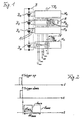
- a trigger signal "trigger up" as shown in the top diagram of Fig.
- the first measuring module M 1 begins to detect the voltage and temperature of the first battery cell B 1 . It then forwards this information to the second measuring module M 2 both as a minimum and also as a maximum voltage value or temperature value.
- the second measuring module M 2 receives this measured variable information and in turn measures voltage and temperature of the second battery cell B 2 .
- the third measuring module M 3 in turn measures the voltage and temperature of the third battery cell B 3 and compares the self-measured voltage value on the one hand with the previous minimum voltage value U min fed to it and on the other hand with the previous maximum voltage value U max applied to it . From the first-mentioned minimum value comparison, the smaller value is forwarded to the next measuring module as the current minimum voltage value. From the last-mentioned maximum value comparison, the larger value is passed on to the next measuring module as the current maximum voltage value. The same applies to the other parameter, the temperature.
- the four extremal value information U min , U max , T min , T max are received by the respective previous measurement module, evaluated according to their own measured values and forwarded to the next measurement module as such updated measurement information until finally the last measurement module M n for the Entity of the individual battery cells B 1 , ..., B n valid voltage and temperature extremes U min , U max , T min , T max outputs, for example, to supply them to the monitoring control unit.
- such a compensation of the trigger signal propagation time can also be achieved by activating the measurement modules M 1 ,..., M n already with the fed-in trigger signal "Trigger up", but then the voltage and temperature measurement information at the last triggered measurement module at the trigger signal feed point be removed opposite end of the measuring module chain.
- a simple extremal value evaluation of the measurement signal information can be achieved when using pulse-width-modulated measurement signals whose pulse width represents the associated measured value. This is illustrated for the voltage signal in the lower diagram of FIG. 2. There, accordingly, the voltage minimum value signal is shown by a solid line in a pulse width ⁇ t min , which represents the minimum voltage value U min . In the same way, the dotted line voltage maximum value signal is shown in a width ⁇ t max representing the maximum voltage value U max .
- the minimum value evaluation can then take place in the respective measuring module by simply ANDing the own measured value with the previously valid minimum value supplied by the previous measuring module, the result of which represents the newly applicable minimum value, ie the narrower of the two compared signals is selected. In the same way, the maximum value evaluation can be realized by simply ORing the own measured value with the supplied, previously valid maximum value, ie, the respectively wider one of the two compared signals is selected.
- the measuring speed for one measuring cycle is in use such pulse width modulated measurement signals primarily depending on the product of the maximum occurring pulse width with the number of modules n.
- pulse width modulated Measuring signals can be an error addition when forwarding the measured variable information from one to avoid the next measurement module, it just adds up Time differences.
- the measurement value information can also be forwarded and evaluated simply as analog measurement variable information, in particular via extremal values of the observed measurement variables, in the measurement module chain.
- the measured value information can be serially evaluated and forwarded.
- a general advantage of the serial connection of the measuring modules M 1 ,..., M n via the serial signal connection SV is that the measuring modules M 1 ,..., M n do not have to be designed to be voltage-proof.
- a further alternative option for configuring the evaluated and forwarded measured variable information is to use a pulse with a constant pulse width as the measuring signal, which is generated at a time dependent on the measured value to be coded, ie delayed by a time dependent on the measured value relative to a reference time.
- This variant allows the transmission of both a maximum value and a minimum value on a common transmission line without a coded trigger signal in which, for example, the minimum value corresponds to the earliest pulse and the maximum value corresponds to the latest pulse and intervening pulses are not forwarded in each case. It then suffices to have a respective OR comparison between the own measurement signal with the received earliest and the received latest pulse for evaluation with regard to minimum value and maximum value of the respective measurement variable, such as voltage, temperature or pressure. It is only necessary to adjust the constant pulse width between the measuring modules, M 1 ,..., M n .
- the measuring module M 1 , ..., M n each contain a corresponding A / D converter and in the signal evaluation part of the monitoring device, a suitable conventional digital signal processing is implemented.
- each measuring module M 1 ,..., M n is preferably supplied by the associated battery cell B 1 ,..., B n .
- the forwarding of a rating mode control signal can be provided with which the measurement modules M 1 ,..., M n can be switched between different evaluation modes, for example between a rating for maximum voltage during charging operations and a rating for minimum voltage during Unloading operations or alternately between a pressure and a temperature rating or between any other possible rating types. If necessary, then a single measuring signal line is sufficient, via which the measured variable information associated with the respectively active evaluation mode is transmitted.
- the passage of a selection control signal through the measuring module chain can be provided, with which the correspondingly designed measuring modules M 1 ,..., M n can be switched between an actively evaluating state and a passively remaining, merely forwarding state.
- any desired subset of measuring modules can be selected from the measuring module chain whose measured values are used to obtain the corresponding measured quantity information, while the other measuring modules only forward the received measured quantity information unchanged.
- minimum values and / or maximum values of a measured variable for an arbitrary subset of the battery cells B 1 ,..., B n can be determined.
- a parallel coupling of the measuring modules M 1 ,..., M n to a common signal connection SV ' is provided from one or more signal lines.
- the measured variable information and, if appropriate, the trigger and / or control signals are not passed on from one to the next measuring module, but placed in parallel on the common signal connection SV. This can be done for the encoded measured variable information, for example as a voltage jump, which is placed by the respective measuring module on the common signal line.
- Another possible signal conditioning is to place the measurement signal as a constant current signal on the common associated signal line, which can act as a sum line by being terminated with a resistance to one pole of the battery B, in which case the current represents the measured value.
- the variant with a common, parallel signal connection of the measuring modules M 1 ,..., M n is particularly suitable for determining the minimum value and the maximum value of a respective measured variable, without requiring an AND or OR evaluation in the individual measuring modules , If, for example, a measurement signal coding is used as the pulse-width-modulated signal, the maximum value results simply from the pulse width of the total signal on the common signal line to which the measurement modules M 1 ,..., M n output their pulse-width-modulated signals.
- the measuring modules M 1 ,..., M n can be triggered simultaneously with this type of system without a runtime error.
- the capacity used for a galvanic decoupling may possibly already be realized by a conductor track. Incidentally, for this system type with a common signal connection, the corresponding properties and advantages apply, as indicated above for the system type of FIG. 1 with serial signal connection.
- each measuring module M 1 ,..., M n contains the corresponding resistor R, which can be controllably coupled to the battery cell in question in parallel therewith, and an associated discharge control circuit 2.
- Its resistance value is primarily determined by the difference between the self-discharge characteristics of all the battery cells B 1 , ..., B n and the time duration within which a maximum charge state difference is to be compensated. A lower limit of the resistance value may be given by a maximum allowed local heating. Dissipation loss in high charge throughput applications with small capacity batteries adds only insignificantly to the usual, other losses and is therefore tolerable.
- the respective measuring module knows whether it has to discharge its associated battery cell or not, the previously determined information about the minimum voltage value U min is made available to all measuring modules M 1 ,..., M n , in the example of FIG. that it is successively forwarded from the last measuring module M n to the other measuring modules up to the first measuring module M 1 .
- Each measuring module M 1 ,..., M n then compares the minimum voltage value U min with its own measured voltage value of the associated battery cell B 1 ,..., B n and activates the dissipative discharging process if its own voltage value is more than a predetermined one Distance above the minimum voltage value U min is.
- the already required trigger pulse or the trigger signal connection TR H , TR R can be used in an advantageous realization.
- the predetermined minimum value which represents the tolerance band in which all cell charge states should lie, can be added to the minimum voltage value, so that each measurement module M 1 ,..., M n only has its own voltage measurement value via the trigger line TR H , TR R must compare minimum transmitted voltage U min to decide whether it makes a dissipative discharge of its cell.
Abstract
Description
- Fig. 1
- ein Blockschaltbild einer mehrzelligen Batterie mit zugeordneter elektronischer Überwachungseinrichtung mit seriell verschalteten Messmodulen,
- Fig. 2
- eine schematische Darstellung von Triggersignalen und Spannungsmesssignalen zur Erläuterung der Betriebsweise der Überwachungseinrichtung von Fig. 1 und
- Fig. 3
- eine Darstellung entsprechend Fig. 1, jedoch für eine Variante mit parallel verschalteten Messmodulen.
Claims (9)
- Elektronische Überwachungseinrichtung für einen aus mehreren hintereinandergeschalteten Speichereinheiten (B1, ..., Bn) bestehenden elektrischen Energiespeicher (B), mitdadurch gekennzeichnet , dassden Speichereinheiten jeweils zugeordneten Messmodulen (M1, ..., Mn), die wenigstens eine speicherzustandsindikative Messgröße an der zugeordneten Speichereinheit messen,die Messmodule (M1, ..., Mn) parallel an eine gemeinsame Signalverbindung (SV') angeschlossen und darauf ausgelegt sind, ihre erfassten Messgrößenwerte parallel in einer hinsichtlich Extremalwertbildung aus den Messgrößenwerten auf der gemeinsamen Signalverbindung codierten Form zu übertragen.
- Elektronische Überwachungseinrichtung nach Anspruch 1, weiter
dadurch gekennzeichnet , dass
die Messmodule (M1, ..., Mn) über eine Kapazität (C) oder eine Induktivität an die gemeinsame Signalverbindung (SV') angekoppelt sind. - Elektronische Überwachungseinrichtung nach einem der Ansprüche 1 oder 2, weiter
dadurch gekennzeichnet , dass
Mittel zum Umschalten der Messmodule (M1, ..., Mn) zwischen einem aktivierten und einem deaktivierten Zustand durch ein Betriebsmodus-Steuersignal vorgesehen sind. - Elektronische Überwachungseinrichtung nach einem der Ansprüche 1, 2 oder 3, weiter
dadurch gekennzeichnet , dass
Mittel zur Umschaltung der Messmodule (M1, ..., Mn) zwischen verschiedenen Bewertungsmodi durch ein Bewertungsmodus-Steuersignal vorgesehen sind. - Elektronische Überwachungseinrichtung nach einem der Ansprüche 1 bis 4, weiter
dadurch gekennzeichnet , dass
Mittel zur selektiven Steuerung der Messmodule (M1, ..., Mn) in einen voll aktiven oder in einen passiven, signalweiterleitenden Betriebszustand vorgesehen sind. - Elektronische Überwachungseinrichtung nach einem der Ansprüche 1 bis 5, weiter
dadurch gekennzeichnet , dass
die Messmodule (M1, ..., Mn) zur Codierung der Messwerte in pulsweitenmodulierte Messsignale eingerichtet sind. - Elektronische Überwachungseinrichtung nach einem der Ansprüche 1 bis 5, weiter
dadurch gekennzeichnet , dass
die Messmodule (M1, ..., Mn) zur Codierung der Messwerte in Pulssignale mit vom Messwert abhängiger Pulsverzögerung eingerichtet sind. - Elektronische Überwachungseinrichtung nach einem der Ansprüche 1 bis 5, weiter
dadurch gekennzeichnet , dass
die Messmodule (M1, ..., Mn) zur Codierung der Messwerte in Konstantstrom-Messsignale mit messwertabhängiger Stromstärke eingerichtet sind. - Elektronische Überwachungseinrichtung nach einem der Ansprüche 1 bis 8, weiter
dadurch gekennzeichnet , dass jedes Messmodul (M1, ..., Mn) einen elektrischen Widerstand sowie Entlademittel zur steuerbaren, entladenden Ankopplung des Widerstands an die zugeordnete Speichereinheit aufweist.
Applications Claiming Priority (3)
| Application Number | Priority Date | Filing Date | Title |
|---|---|---|---|
| DE19921675A DE19921675A1 (de) | 1999-05-11 | 1999-05-11 | Methode zur Erfassung von Kenn- und Meßgrößen von Batteriesätzen und dergleichen |
| DE19921675 | 1999-05-11 | ||
| EP00931193A EP1127280B1 (de) | 1999-05-11 | 2000-05-11 | Elektronische überwachungseinrichtung für mehrteiligen elektrischen energiespeicher |
Related Parent Applications (1)
| Application Number | Title | Priority Date | Filing Date |
|---|---|---|---|
| EP00931193A Division EP1127280B1 (de) | 1999-05-11 | 2000-05-11 | Elektronische überwachungseinrichtung für mehrteiligen elektrischen energiespeicher |
Publications (2)
| Publication Number | Publication Date |
|---|---|
| EP1596213A1 true EP1596213A1 (de) | 2005-11-16 |
| EP1596213B1 EP1596213B1 (de) | 2007-10-10 |
Family
ID=7907696
Family Applications (2)
| Application Number | Title | Priority Date | Filing Date |
|---|---|---|---|
| EP05016523A Expired - Lifetime EP1596213B1 (de) | 1999-05-11 | 2000-05-11 | Elektronische Überwachungseinrichtung für mehrteiligen elektrischen Energiespeicher |
| EP00931193A Expired - Lifetime EP1127280B1 (de) | 1999-05-11 | 2000-05-11 | Elektronische überwachungseinrichtung für mehrteiligen elektrischen energiespeicher |
Family Applications After (1)
| Application Number | Title | Priority Date | Filing Date |
|---|---|---|---|
| EP00931193A Expired - Lifetime EP1127280B1 (de) | 1999-05-11 | 2000-05-11 | Elektronische überwachungseinrichtung für mehrteiligen elektrischen energiespeicher |
Country Status (5)
| Country | Link |
|---|---|
| US (1) | US6621247B1 (de) |
| EP (2) | EP1596213B1 (de) |
| JP (1) | JP4602565B2 (de) |
| DE (3) | DE19921675A1 (de) |
| WO (1) | WO2000068700A2 (de) |
Cited By (2)
| Publication number | Priority date | Publication date | Assignee | Title |
|---|---|---|---|---|
| CN103165947A (zh) * | 2011-12-19 | 2013-06-19 | 株式会社东芝 | 蓄电装置及其维修方法 |
| US9660303B2 (en) | 2008-08-25 | 2017-05-23 | Robert Bosch Gmbh | Battery monitoring system |
Families Citing this family (25)
| Publication number | Priority date | Publication date | Assignee | Title |
|---|---|---|---|---|
| JP3895960B2 (ja) | 2001-10-03 | 2007-03-22 | 本田技研工業株式会社 | 燃料電池スタック |
| JP4506075B2 (ja) * | 2002-11-27 | 2010-07-21 | トヨタ自動車株式会社 | 燃料電池の診断装置 |
| DE10260373A1 (de) * | 2002-12-13 | 2004-06-24 | Volkswagen Ag | Verfahren und Vorrichtung zur Funktionszustandsprüfung eines elektrischen Energie-Systems sowie ein zugehöriges elektrisches Energie-System |
| DE10260894A1 (de) * | 2002-12-17 | 2004-07-22 | Fraunhofer-Gesellschaft zur Förderung der angewandten Forschung e.V. | Verfahren und Schaltungsanordnung zur Vermessung von elektrochemischen Zellen in einer Serienverschaltung |
| DE10260176B4 (de) | 2002-12-20 | 2006-05-18 | Daimlerchrysler Ag | Vorrichtung zur Datenerfassung |
| DE10260177B4 (de) * | 2002-12-20 | 2009-01-22 | Daimler Ag | Verfahren und Vorrichtung zur Datenerfassung |
| FR2862558B1 (fr) | 2003-11-20 | 2006-04-28 | Pellenc Sa | Outil portatif electrique autonome de puissance |
| KR101118377B1 (ko) * | 2004-06-30 | 2012-03-08 | 포드 모터 캄파니 | 차량 정보 디스플레이부 및 차량 정보 디스플레이 방법 |
| DE102004062186A1 (de) * | 2004-12-23 | 2006-07-13 | Temic Automotive Electric Motors Gmbh | Ladungsumverteilungsschaltung |
| JP4584758B2 (ja) * | 2005-04-07 | 2010-11-24 | 新神戸電機株式会社 | 電池モジュール用制御システム |
| DE102005028831A1 (de) * | 2005-06-15 | 2006-12-28 | Aesculap Ag & Co. Kg | Verfahren und chirurgisches Navigationssystem zur Herstellung einer Aufnahmevertiefung für eine Hüftgelenkpfanne |
| FR2890175B1 (fr) * | 2005-08-30 | 2008-03-14 | Johnson Controls Tech Co | Procede et dispositif de mesure de tensions differentielles aux bornes des elements d'une batterie avec transformation en signal periodique |
| EP1977263B1 (de) | 2006-01-26 | 2011-10-12 | Johnson Controls Technology Company | Einrichtung zum überwachen der zellenspannung |
| JP2008090354A (ja) * | 2006-09-29 | 2008-04-17 | Hitachi Ltd | 電源障害監視方法及びその装置 |
| FR2908323B1 (fr) * | 2006-11-09 | 2009-01-16 | Parrot Sa | Procede de definition d'un referentiel commun pour un systeme de jeux video |
| FR2908322B1 (fr) * | 2006-11-09 | 2009-03-06 | Parrot Sa | Procede de definition de zone de jeux pour un systeme de jeux video |
| FR2908324B1 (fr) * | 2006-11-09 | 2009-01-16 | Parrot Sa | Procede d'ajustement d'affichage pour un systeme de jeux video |
| DE102007049671A1 (de) * | 2007-10-17 | 2009-04-30 | Aesculap Ag | Verfahren und Vorrichtung zur Bestimmung der Frontalebene des Beckenknochens |
| DE102007049668B3 (de) * | 2007-10-17 | 2009-04-16 | Aesculap Ag | Verfahren und Vorrichtung zur Bestimmung der Winkellage einer Hüftgelenkpfanne in einem Beckenknochen |
| US8386104B2 (en) * | 2009-06-01 | 2013-02-26 | Ford Global Technologies, Llc | System and method for displaying power flow in a hybrid vehicle |
| EP2385604A1 (de) | 2010-05-07 | 2011-11-09 | Brusa Elektronik AG | Verfahren und Zellüberwachungseinheit zur Überwachung eines Akkumulators, zentrale Überwachungseinheit und Akkumulator |
| DE102011004980A1 (de) * | 2011-03-02 | 2012-09-06 | Sb Limotive Co., Ltd. | Batteriemodul und Batterie mit redundanter Zellspannungserfassung |
| US20150039752A1 (en) * | 2013-07-30 | 2015-02-05 | Edward Hague | Advanced BACNet router |
| CN105094267A (zh) * | 2015-07-29 | 2015-11-25 | 英业达科技有限公司 | 供电装置 |
| US10847835B2 (en) * | 2017-12-13 | 2020-11-24 | William Jeffrey Schlanger | Battery management system for battery banks with a small number of cells |
Citations (3)
| Publication number | Priority date | Publication date | Assignee | Title |
|---|---|---|---|---|
| US5099211A (en) * | 1990-03-26 | 1992-03-24 | Nowak Dieter K | Battery voltage measurement system |
| US5578927A (en) * | 1993-12-09 | 1996-11-26 | Saft | Measurement circuit for a modular system of cells electrically connected in series, in particular for electrical accumlator batteries |
| US5760587A (en) * | 1995-06-28 | 1998-06-02 | Ford Global Technologies, Inc. | Battery measurement method |
Family Cites Families (7)
| Publication number | Priority date | Publication date | Assignee | Title |
|---|---|---|---|---|
| JPH08140204A (ja) * | 1994-11-08 | 1996-05-31 | Matsushita Electric Ind Co Ltd | 組電池の監視装置 |
| JP3335018B2 (ja) * | 1994-12-05 | 2002-10-15 | 松下電器産業株式会社 | 組電池の監視装置 |
| DE19503917C2 (de) * | 1995-02-07 | 1996-11-21 | Mc Micro Compact Car Ag | Elektronische Batterieüberwachungseinrichtung |
| JP3922655B2 (ja) * | 1996-07-12 | 2007-05-30 | 株式会社東京アールアンドデー | 電源装置の制御システムおよび電源装置の制御方法 |
| US6133709A (en) * | 1997-01-21 | 2000-10-17 | Metrixx Limited | Signalling system |
| WO1998032181A2 (en) | 1997-01-21 | 1998-07-23 | Metrixx Limited | Signalling system |
| JP3930171B2 (ja) * | 1998-12-03 | 2007-06-13 | 株式会社日本自動車部品総合研究所 | 組電池の監視装置 |
-
1999
- 1999-05-11 DE DE19921675A patent/DE19921675A1/de not_active Withdrawn
-
2000
- 2000-05-11 JP JP2000616433A patent/JP4602565B2/ja not_active Expired - Fee Related
- 2000-05-11 US US09/743,508 patent/US6621247B1/en not_active Expired - Lifetime
- 2000-05-11 DE DE50014716T patent/DE50014716D1/de not_active Expired - Lifetime
- 2000-05-11 DE DE50012228T patent/DE50012228D1/de not_active Expired - Lifetime
- 2000-05-11 WO PCT/EP2000/004273 patent/WO2000068700A2/de active IP Right Grant
- 2000-05-11 EP EP05016523A patent/EP1596213B1/de not_active Expired - Lifetime
- 2000-05-11 EP EP00931193A patent/EP1127280B1/de not_active Expired - Lifetime
Patent Citations (3)
| Publication number | Priority date | Publication date | Assignee | Title |
|---|---|---|---|---|
| US5099211A (en) * | 1990-03-26 | 1992-03-24 | Nowak Dieter K | Battery voltage measurement system |
| US5578927A (en) * | 1993-12-09 | 1996-11-26 | Saft | Measurement circuit for a modular system of cells electrically connected in series, in particular for electrical accumlator batteries |
| US5760587A (en) * | 1995-06-28 | 1998-06-02 | Ford Global Technologies, Inc. | Battery measurement method |
Cited By (3)
| Publication number | Priority date | Publication date | Assignee | Title |
|---|---|---|---|---|
| US9660303B2 (en) | 2008-08-25 | 2017-05-23 | Robert Bosch Gmbh | Battery monitoring system |
| CN103165947A (zh) * | 2011-12-19 | 2013-06-19 | 株式会社东芝 | 蓄电装置及其维修方法 |
| CN103165947B (zh) * | 2011-12-19 | 2015-05-20 | 株式会社东芝 | 蓄电装置及其维修方法 |
Also Published As
| Publication number | Publication date |
|---|---|
| US6621247B1 (en) | 2003-09-16 |
| WO2000068700A2 (de) | 2000-11-16 |
| WO2000068700A3 (de) | 2001-04-19 |
| EP1127280A2 (de) | 2001-08-29 |
| JP2002544645A (ja) | 2002-12-24 |
| DE50012228D1 (de) | 2006-04-20 |
| JP4602565B2 (ja) | 2010-12-22 |
| DE19921675A1 (de) | 2000-11-16 |
| DE50014716D1 (de) | 2007-11-22 |
| EP1596213B1 (de) | 2007-10-10 |
| EP1127280B1 (de) | 2006-02-15 |
Similar Documents
| Publication | Publication Date | Title |
|---|---|---|
| EP1596213B1 (de) | Elektronische Überwachungseinrichtung für mehrteiligen elektrischen Energiespeicher | |
| DE102004006022B4 (de) | Vorrichtungen zum Entladen eines Batterieverbunds, der aus einer Vielzahl von Sekundärbatterien besteht | |
| EP0432639B1 (de) | Überwachungseinrichtung für Akkumulatoren | |
| DE102006005334B4 (de) | Verfahren zur Überwachung und/oder Steuerung oder Regelung der Spannung wenigstens einer Zellgruppe in einem Zellenverbund eines Energiespeichers sowie Zellgruppenlogik und Zentral-Logik zur Durchführung des Verfahrens | |
| EP2419990B1 (de) | Erweiterte batteriediagnose bei traktionsbatterien | |
| EP3701584B1 (de) | Verfahren zum auf- oder entladen eines energiespeichers | |
| DE60208892T2 (de) | Verfahren und vorrichtung zum laden einer wiederaufladbaren batterie mit nicht flüssigem elektrolyt | |
| EP1728305B1 (de) | Vorrichtung zur ladeverteilung und berwachung von mehreren akkumulatoren | |
| EP3593435B1 (de) | Verfahren zum betreiben eines modularen batteriespeichersystems und modulares batteriespeichersystem | |
| EP2385604A1 (de) | Verfahren und Zellüberwachungseinheit zur Überwachung eines Akkumulators, zentrale Überwachungseinheit und Akkumulator | |
| EP2482422A1 (de) | Vorrichtung und Verfahren zum Überwachen und Symmetrieren eines mehrzelligen Energiespeicherstapels | |
| EP0432640A2 (de) | Überwachungseinrichtung für Akkumulatoren | |
| EP4052321B1 (de) | Verfahren zum aufladen und/ oder entladen eines wiederaufladbaren energiespeichers | |
| WO2022064003A1 (de) | Verfahren zur bestimmung des zustands eines wiederaufladbaren batteriesystems | |
| EP2858849B1 (de) | Verfahren zur bestimmung eines ohmschen innenwiderstandes eines batteriemoduls, batteriemanagementsystem und kraftfahrzeug | |
| DE69730802T2 (de) | Regler für eine kraftfahrzeug eigene batterie | |
| EP2852997B1 (de) | Konditionierungsvorrichtung und verfahren zum zum konditionieren eines datenkanals einer zelle eines elektrischen energiespeichers | |
| DE19958098C2 (de) | Stromversorgung für Fahrzeuge | |
| DE102012012765A1 (de) | Verfahren und Vorrichtung zum Laden eines elektrischen Energiespeichers | |
| EP1480051A2 (de) | Verfahren und Vorrichtung zur Bestimmung der Hochstrombelastbarkeit einer Batterie | |
| EP0487784B1 (de) | Verfahren zum Erkennen eines Ladungsgrenzwertes einer Batterie | |
| DE112013006271T5 (de) | Bordsteuerungsvorrichtung | |
| DE19652173A1 (de) | Verfahren zur Prüfung der Funktionsfähigkeit von Akkumulatoren | |
| DE102005025954A1 (de) | Ladesystem für Batterien sowie Verfahren zum Betrieb eines Ladesystems für Batterien | |
| EP3985833A1 (de) | Laden einer akkumulatoreinheit |
Legal Events
| Date | Code | Title | Description |
|---|---|---|---|
| PUAI | Public reference made under article 153(3) epc to a published international application that has entered the european phase |
Free format text: ORIGINAL CODE: 0009012 |
|
| AC | Divisional application: reference to earlier application |
Ref document number: 1127280 Country of ref document: EP Kind code of ref document: P |
|
| AK | Designated contracting states |
Kind code of ref document: A1 Designated state(s): DE FR GB |
|
| AX | Request for extension of the european patent |
Extension state: AL LT LV MK RO SI |
|
| AKX | Designation fees paid | ||
| 17P | Request for examination filed |
Effective date: 20060725 |
|
| RBV | Designated contracting states (corrected) |
Designated state(s): DE FR GB |
|
| 17Q | First examination report despatched |
Effective date: 20060825 |
|
| GRAP | Despatch of communication of intention to grant a patent |
Free format text: ORIGINAL CODE: EPIDOSNIGR1 |
|
| RAP1 | Party data changed (applicant data changed or rights of an application transferred) |
Owner name: DAIMLERCHRYSLER AG |
|
| GRAS | Grant fee paid |
Free format text: ORIGINAL CODE: EPIDOSNIGR3 |
|
| GRAA | (expected) grant |
Free format text: ORIGINAL CODE: 0009210 |
|
| AC | Divisional application: reference to earlier application |
Ref document number: 1127280 Country of ref document: EP Kind code of ref document: P |
|
| AK | Designated contracting states |
Kind code of ref document: B1 Designated state(s): DE FR GB |
|
| REG | Reference to a national code |
Ref country code: GB Ref legal event code: FG4D Free format text: NOT ENGLISH |
|
| GBT | Gb: translation of ep patent filed (gb section 77(6)(a)/1977) |
Effective date: 20071010 |
|
| REF | Corresponds to: |
Ref document number: 50014716 Country of ref document: DE Date of ref document: 20071122 Kind code of ref document: P |
|
| RAP2 | Party data changed (patent owner data changed or rights of a patent transferred) |
Owner name: DAIMLER AG |
|
| ET | Fr: translation filed | ||
| PLBE | No opposition filed within time limit |
Free format text: ORIGINAL CODE: 0009261 |
|
| STAA | Information on the status of an ep patent application or granted ep patent |
Free format text: STATUS: NO OPPOSITION FILED WITHIN TIME LIMIT |
|
| 26N | No opposition filed |
Effective date: 20080711 |
|
| REG | Reference to a national code |
Ref country code: FR Ref legal event code: CD |
|
| REG | Reference to a national code |
Ref country code: FR Ref legal event code: PLFP Year of fee payment: 17 |
|
| PGFP | Annual fee paid to national office [announced via postgrant information from national office to epo] |
Ref country code: GB Payment date: 20160531 Year of fee payment: 17 |
|
| PGFP | Annual fee paid to national office [announced via postgrant information from national office to epo] |
Ref country code: FR Payment date: 20160531 Year of fee payment: 17 |
|
| PGFP | Annual fee paid to national office [announced via postgrant information from national office to epo] |
Ref country code: DE Payment date: 20160729 Year of fee payment: 17 |
|
| REG | Reference to a national code |
Ref country code: DE Ref legal event code: R119 Ref document number: 50014716 Country of ref document: DE |
|
| GBPC | Gb: european patent ceased through non-payment of renewal fee |
Effective date: 20170511 |
|
| REG | Reference to a national code |
Ref country code: FR Ref legal event code: ST Effective date: 20180131 |
|
| PG25 | Lapsed in a contracting state [announced via postgrant information from national office to epo] |
Ref country code: GB Free format text: LAPSE BECAUSE OF NON-PAYMENT OF DUE FEES Effective date: 20170511 Ref country code: DE Free format text: LAPSE BECAUSE OF NON-PAYMENT OF DUE FEES Effective date: 20171201 |
|
| PG25 | Lapsed in a contracting state [announced via postgrant information from national office to epo] |
Ref country code: FR Free format text: LAPSE BECAUSE OF NON-PAYMENT OF DUE FEES Effective date: 20170531 |