EP1596898B1 - Balloon catheter - Google Patents
Balloon catheter Download PDFInfo
- Publication number
- EP1596898B1 EP1596898B1 EP04715085A EP04715085A EP1596898B1 EP 1596898 B1 EP1596898 B1 EP 1596898B1 EP 04715085 A EP04715085 A EP 04715085A EP 04715085 A EP04715085 A EP 04715085A EP 1596898 B1 EP1596898 B1 EP 1596898B1
- Authority
- EP
- European Patent Office
- Prior art keywords
- catheter
- transition
- proximal
- balloon
- section
- Prior art date
- Legal status (The legal status is an assumption and is not a legal conclusion. Google has not performed a legal analysis and makes no representation as to the accuracy of the status listed.)
- Expired - Lifetime
Links
- 230000007704 transition Effects 0.000 claims abstract description 79
- 229920000642 polymer Polymers 0.000 claims description 24
- 239000000203 mixture Substances 0.000 claims description 18
- 230000002792 vascular Effects 0.000 claims description 5
- 238000002399 angioplasty Methods 0.000 claims description 4
- 229920002614 Polyether block amide Polymers 0.000 description 25
- 239000004698 Polyethylene Substances 0.000 description 25
- 239000000463 material Substances 0.000 description 18
- 229920000339 Marlex Polymers 0.000 description 10
- 238000013461 design Methods 0.000 description 10
- 229920003300 Plexar® Polymers 0.000 description 9
- 230000004044 response Effects 0.000 description 9
- 229920000299 Nylon 12 Polymers 0.000 description 8
- 239000004952 Polyamide Substances 0.000 description 7
- 238000000034 method Methods 0.000 description 7
- 229920002647 polyamide Polymers 0.000 description 7
- 239000012530 fluid Substances 0.000 description 6
- 230000000712 assembly Effects 0.000 description 5
- 238000000429 assembly Methods 0.000 description 5
- 229920001778 nylon Polymers 0.000 description 5
- 238000012360 testing method Methods 0.000 description 5
- 239000008188 pellet Substances 0.000 description 4
- 239000004677 Nylon Substances 0.000 description 3
- 229920006020 amorphous polyamide Polymers 0.000 description 3
- 230000003247 decreasing effect Effects 0.000 description 3
- 210000001367 artery Anatomy 0.000 description 2
- 229910001566 austenite Inorganic materials 0.000 description 2
- 230000036760 body temperature Effects 0.000 description 2
- 238000010276 construction Methods 0.000 description 2
- 210000004351 coronary vessel Anatomy 0.000 description 2
- 229920001971 elastomer Polymers 0.000 description 2
- 239000000806 elastomer Substances 0.000 description 2
- 238000001125 extrusion Methods 0.000 description 2
- 229920001903 high density polyethylene Polymers 0.000 description 2
- -1 polyethylene Polymers 0.000 description 2
- 229920000573 polyethylene Polymers 0.000 description 2
- 230000002787 reinforcement Effects 0.000 description 2
- 238000003466 welding Methods 0.000 description 2
- OKTJSMMVPCPJKN-UHFFFAOYSA-N Carbon Chemical compound [C] OKTJSMMVPCPJKN-UHFFFAOYSA-N 0.000 description 1
- JHWNWJKBPDFINM-UHFFFAOYSA-N Laurolactam Chemical compound O=C1CCCCCCCCCCCN1 JHWNWJKBPDFINM-UHFFFAOYSA-N 0.000 description 1
- 206010028980 Neoplasm Diseases 0.000 description 1
- 239000004642 Polyimide Substances 0.000 description 1
- 239000004809 Teflon Substances 0.000 description 1
- 229910045601 alloy Inorganic materials 0.000 description 1
- 239000000956 alloy Substances 0.000 description 1
- 230000017531 blood circulation Effects 0.000 description 1
- 210000004204 blood vessel Anatomy 0.000 description 1
- 239000007767 bonding agent Substances 0.000 description 1
- 210000002302 brachial artery Anatomy 0.000 description 1
- 229920006018 co-polyamide Polymers 0.000 description 1
- 230000000052 comparative effect Effects 0.000 description 1
- 238000005520 cutting process Methods 0.000 description 1
- 230000001419 dependent effect Effects 0.000 description 1
- 210000003238 esophagus Anatomy 0.000 description 1
- QHSJIZLJUFMIFP-UHFFFAOYSA-N ethene;1,1,2,2-tetrafluoroethene Chemical group C=C.FC(F)=C(F)F QHSJIZLJUFMIFP-UHFFFAOYSA-N 0.000 description 1
- 229920000840 ethylene tetrafluoroethylene copolymer Polymers 0.000 description 1
- 210000001105 femoral artery Anatomy 0.000 description 1
- 229920002457 flexible plastic Polymers 0.000 description 1
- 229920002313 fluoropolymer Polymers 0.000 description 1
- 239000004811 fluoropolymer Substances 0.000 description 1
- 238000002594 fluoroscopy Methods 0.000 description 1
- 210000001035 gastrointestinal tract Anatomy 0.000 description 1
- 229910002804 graphite Inorganic materials 0.000 description 1
- 239000010439 graphite Substances 0.000 description 1
- 239000004700 high-density polyethylene Substances 0.000 description 1
- 238000003780 insertion Methods 0.000 description 1
- 230000037431 insertion Effects 0.000 description 1
- 229920000092 linear low density polyethylene Polymers 0.000 description 1
- 238000004519 manufacturing process Methods 0.000 description 1
- 229910000734 martensite Inorganic materials 0.000 description 1
- 238000005259 measurement Methods 0.000 description 1
- 229940127554 medical product Drugs 0.000 description 1
- 239000002184 metal Substances 0.000 description 1
- 238000012544 monitoring process Methods 0.000 description 1
- 229910001000 nickel titanium Inorganic materials 0.000 description 1
- 230000037361 pathway Effects 0.000 description 1
- 229920003023 plastic Polymers 0.000 description 1
- 239000004033 plastic Substances 0.000 description 1
- 229920000768 polyamine Polymers 0.000 description 1
- 229920001721 polyimide Polymers 0.000 description 1
- 230000008569 process Effects 0.000 description 1
- 210000002321 radial artery Anatomy 0.000 description 1
- 239000011347 resin Substances 0.000 description 1
- 229920005989 resin Polymers 0.000 description 1
- 239000010935 stainless steel Substances 0.000 description 1
- 229910001220 stainless steel Inorganic materials 0.000 description 1
- 229920002725 thermoplastic elastomer Polymers 0.000 description 1
- 230000009466 transformation Effects 0.000 description 1
- 210000001635 urinary tract Anatomy 0.000 description 1
- XLYOFNOQVPJJNP-UHFFFAOYSA-N water Substances O XLYOFNOQVPJJNP-UHFFFAOYSA-N 0.000 description 1
Images


Classifications
-
- A—HUMAN NECESSITIES
- A61—MEDICAL OR VETERINARY SCIENCE; HYGIENE
- A61M—DEVICES FOR INTRODUCING MEDIA INTO, OR ONTO, THE BODY; DEVICES FOR TRANSDUCING BODY MEDIA OR FOR TAKING MEDIA FROM THE BODY; DEVICES FOR PRODUCING OR ENDING SLEEP OR STUPOR
- A61M25/00—Catheters; Hollow probes
- A61M25/10—Balloon catheters
- A61M25/1027—Making of balloon catheters
-
- A—HUMAN NECESSITIES
- A61—MEDICAL OR VETERINARY SCIENCE; HYGIENE
- A61L—METHODS OR APPARATUS FOR STERILISING MATERIALS OR OBJECTS IN GENERAL; DISINFECTION, STERILISATION OR DEODORISATION OF AIR; CHEMICAL ASPECTS OF BANDAGES, DRESSINGS, ABSORBENT PADS OR SURGICAL ARTICLES; MATERIALS FOR BANDAGES, DRESSINGS, ABSORBENT PADS OR SURGICAL ARTICLES
- A61L29/00—Materials for catheters, medical tubing, cannulae, or endoscopes or for coating catheters
- A61L29/04—Macromolecular materials
-
- A—HUMAN NECESSITIES
- A61—MEDICAL OR VETERINARY SCIENCE; HYGIENE
- A61L—METHODS OR APPARATUS FOR STERILISING MATERIALS OR OBJECTS IN GENERAL; DISINFECTION, STERILISATION OR DEODORISATION OF AIR; CHEMICAL ASPECTS OF BANDAGES, DRESSINGS, ABSORBENT PADS OR SURGICAL ARTICLES; MATERIALS FOR BANDAGES, DRESSINGS, ABSORBENT PADS OR SURGICAL ARTICLES
- A61L29/00—Materials for catheters, medical tubing, cannulae, or endoscopes or for coating catheters
- A61L29/12—Composite materials, i.e. containing one material dispersed in a matrix of the same or different material
- A61L29/126—Composite materials, i.e. containing one material dispersed in a matrix of the same or different material having a macromolecular matrix
-
- A—HUMAN NECESSITIES
- A61—MEDICAL OR VETERINARY SCIENCE; HYGIENE
- A61L—METHODS OR APPARATUS FOR STERILISING MATERIALS OR OBJECTS IN GENERAL; DISINFECTION, STERILISATION OR DEODORISATION OF AIR; CHEMICAL ASPECTS OF BANDAGES, DRESSINGS, ABSORBENT PADS OR SURGICAL ARTICLES; MATERIALS FOR BANDAGES, DRESSINGS, ABSORBENT PADS OR SURGICAL ARTICLES
- A61L29/00—Materials for catheters, medical tubing, cannulae, or endoscopes or for coating catheters
- A61L29/14—Materials characterised by their function or physical properties, e.g. lubricating compositions
-
- A—HUMAN NECESSITIES
- A61—MEDICAL OR VETERINARY SCIENCE; HYGIENE
- A61M—DEVICES FOR INTRODUCING MEDIA INTO, OR ONTO, THE BODY; DEVICES FOR TRANSDUCING BODY MEDIA OR FOR TAKING MEDIA FROM THE BODY; DEVICES FOR PRODUCING OR ENDING SLEEP OR STUPOR
- A61M25/00—Catheters; Hollow probes
- A61M25/0043—Catheters; Hollow probes characterised by structural features
- A61M25/0045—Catheters; Hollow probes characterised by structural features multi-layered, e.g. coated
-
- A—HUMAN NECESSITIES
- A61—MEDICAL OR VETERINARY SCIENCE; HYGIENE
- A61M—DEVICES FOR INTRODUCING MEDIA INTO, OR ONTO, THE BODY; DEVICES FOR TRANSDUCING BODY MEDIA OR FOR TAKING MEDIA FROM THE BODY; DEVICES FOR PRODUCING OR ENDING SLEEP OR STUPOR
- A61M25/00—Catheters; Hollow probes
- A61M2025/0004—Catheters; Hollow probes having two or more concentrically arranged tubes for forming a concentric catheter system
-
- A—HUMAN NECESSITIES
- A61—MEDICAL OR VETERINARY SCIENCE; HYGIENE
- A61M—DEVICES FOR INTRODUCING MEDIA INTO, OR ONTO, THE BODY; DEVICES FOR TRANSDUCING BODY MEDIA OR FOR TAKING MEDIA FROM THE BODY; DEVICES FOR PRODUCING OR ENDING SLEEP OR STUPOR
- A61M2205/00—General characteristics of the apparatus
- A61M2205/70—General characteristics of the apparatus with testing or calibration facilities
-
- A—HUMAN NECESSITIES
- A61—MEDICAL OR VETERINARY SCIENCE; HYGIENE
- A61M—DEVICES FOR INTRODUCING MEDIA INTO, OR ONTO, THE BODY; DEVICES FOR TRANSDUCING BODY MEDIA OR FOR TAKING MEDIA FROM THE BODY; DEVICES FOR PRODUCING OR ENDING SLEEP OR STUPOR
- A61M25/00—Catheters; Hollow probes
- A61M25/0043—Catheters; Hollow probes characterised by structural features
- A61M25/0054—Catheters; Hollow probes characterised by structural features with regions for increasing flexibility
-
- A—HUMAN NECESSITIES
- A61—MEDICAL OR VETERINARY SCIENCE; HYGIENE
- A61M—DEVICES FOR INTRODUCING MEDIA INTO, OR ONTO, THE BODY; DEVICES FOR TRANSDUCING BODY MEDIA OR FOR TAKING MEDIA FROM THE BODY; DEVICES FOR PRODUCING OR ENDING SLEEP OR STUPOR
- A61M25/00—Catheters; Hollow probes
- A61M25/10—Balloon catheters
- A61M25/104—Balloon catheters used for angioplasty
Definitions
- This invention relates to balloon catheters.
- the body includes various passageways such as arteries, other blood vessels, and other body lumens. These passageways sometimes become occluded by a tumor or restricted by plaque. To widen an occluded body vessel, balloon catheters can be used, for example, in angioplasty.
- a balloon catheter can include an inflatable and deflatable balloon carried by a long and narrow catheter body.
- the balloon is initially folded around the catheter body to reduce the radial profile of the balloon catheter for easy insertion into the body.
- the folded balloon can be delivered to a target location in the vessel, e.g., a portion occluded by plaque, by threading the balloon catheter over a guide wire emplaced in the vessel.
- the balloon is then inflated, e.g., by introducing a fluid into the interior of the balloon. Inflating the balloon can radially expand the vessel so that the vessel can permit an increased rate of blood flow.
- the balloon is deflated and withdrawn from the body.
- the balloon catheter can also be used to position a medical device, such as a stent or a stent-graft, to open and/or to reinforce a blocked passageway.
- a medical device such as a stent or a stent-graft
- the stent can be delivered inside the body by a balloon catheter that supports the stent in a compacted or reduced-size form as the stent is transported to the target site.
- the balloon Upon reaching the site, the balloon can be inflated to deform and to fix the expanded stent at a predetermined position in contact with the lumen wall. The balloon can then be deflated, and the catheter withdrawn.
- One common balloon catheter design includes a coaxial arrangement of an inner tube surrounded by an outer tube.
- the inner tube typically includes a lumen that can be used for delivering the device over a guide wire.
- Inflation fluid passes between the inner and outer tubes.
- An example of this design is described in Arney U.S. 5,047,045 .
- US-A-6 045 547 discloses a multi-layer catheter tube section providing gradually increasing flexibility.
- One catheter tube section has a first, inner layer formed of a flexible material and a second, outer layer formed of a stiffer material.
- the outer layer tapers distally, having decreasing layer thickness with increasing distal position.
- the decreasing wall thickness provides a decreasing stiffness contribution which imparts increasing flexibility to the catheter portions having a smaller outer layer.
- the tube sections can be joined end to end to form longer catheter regions having a greater number of gradual flexibility changes.
- US-A-5 480 383 discloses a balloon dilatation having a catheter shaft with inner and outer tubular members with the proximal portion of the inner tubular member being formed of a pseudoelastic NiTi alloy having an Af at or below body temperature.
- the austenite phase is stable at body temperature exhibits a stress induced transformation, to the martensite phase which has a much lower modulus of elasticity than the austenite phase.
- the distal portion of the inner tubular member is formed of a flexible plastic material.
- the junction of the proximal and distal portions of the inner tubular member is preferably supported by a transition sleeve formed of a high strength plastic such as polyimide to provide a smoother transition between the proxima and distal portions of the inner tubular member and in turn the proximal and distal portion of the catheter shaft.
- a transition sleeve formed of a high strength plastic such as polyimide to provide a smoother transition between the proxima and distal portions of the inner tubular member and in turn the proximal and distal portion of the catheter shaft.
- CA-A-2 347 024 discloses a method for making differential stiffness tubing for medical products, such as catheters.
- the method produces a tubing that has a stiff section and a flexible section joined by a relatively short transition section in which the materials of the stiff and flexible sections are wedged into each other in a smooth gradual manner to produce an inseparable bond between the materials without abrupt joints.
- the method also employs a resin modulating system that minimizes the length of the transition section by minimizing the volumes in all flow channels of the co- extrusion head used to produce the tubing.
- US-A-5 676 659 discloses a catheter comprising an inner tubular member, a braided reinforcement layer, and a soft outer layer.
- the inner tubular member extends from a proximal end of the catheter to a first distal location.
- the braided reinforcement layer extends from the proximal end of the catheter to a second distal location which is usually located proximally from the first distal location.
- the soft outer layer extends from the proximal end of the catheter to a third distal location which is usually located distally of the first distal location.
- WO 00/45885 discloses s spiral cut transition member for controlling the transition in stiffness of a catheter from a stiffer more pushable proximal section to a more flexible and trackable distal section and for increasing kink resistance.
- the transition member has a spiral cut provided therein to vary the flexibility of the transition member over its length. The pitch of the spiral cut can be varied to facilitate a gradual transition in flexibility along the catheter.
- the transition member may be used in conjunction with any type of catheter including single-operator-exchange type catheters, over-the wire type catheters, and/or fixed-wire type catheters.
- the catheter in another common design, includes a body defining a guide wire lumen and an inflation lumen arranged side-by-side. Examples of this arrangement are described in Wang U.S. 5,195,969 .
- the present invention relates to a concentric balloon catheter as defined in claim 1.
- Advantageous embodiments are described in the dependent claims.
- a concentric balloon catheter having a polymeric outer tubular member, including a balloon and a polymeric inner tubular member.
- the inner tubular member has a first, proximal section, a second more distal section, and a transition.
- the second section has a column strength and/or flexural modulus of about 75% or less than the column strength of the first section.
- the transition is located, about 1 to 10 cm, about 2 to 9 cm, about 4 to 8 cm from the distal end of the inner tubular member.
- a concentric vascular angioplasty balloon catheter in another aspect, includes an outer tubular member defining a lumen. A balloon is attached to the outer tubular member.
- the catheter also includes an inner tubular member comprising multiple layers located within the lumen of the outer tubular member.
- the inner tubular member has a first, proximal section welded to a second, more distal section to define a transition located proximal of the balloon.
- the inner tubular member has three or more layers in each of the first and second sections and the second section has a column strength less than a column strength of the first section.
- a balloon catheter having a tubular member having a tubular member, a first lumen for delivery over a guidewire and a second lumen for communicating inflation fluid to the balloon.
- the tubular member also has a first proximal section, a second, distal section and a transition.
- the second section has a column strength, per unit length, less than the column strength, per unit length, of the first section and the transition is located about 1.0 cm or more from the distal end of the tubular member.
- the tubular member exhibits improved trackability, e.g. 10, 20, or 30 percent or more improved trackability, when compared to a monolithic tubular member having a column strength intermediate to the column strength of the first and second sections.
- Embodiments may include one or more of the following.
- the transition is in the range of e.g., about 3 to about 8 cm, about 4 to about 7.5 cm, about 4 to about 7 cm from the distal end of the inner tubular member.
- a distance measured from the transition to a distal end of the inner tubular member is no more than about 20 percent (e.g., no more than about 5 percent) of an overall length of the inner tubular member.
- the first section has a column strength, per 2.54 cm, of about 5 g to 20 g and the second section can have a column strength of about 2 to 7 g.
- the second section has a flexural modulus of about 75 percent or less (e.g., between about 20 and 40 percent) of a flexural modulus of a flexural modulus of the first section.
- the location of the transition is located proximal of the balloon.
- the balloon is between about 8 and 40 millimeters in length, the balloon has an inflated diameter of between about 1.5 and 10 millimeters, and/or the balloon includes polyethylene terethalate or nylon.
- the transition can also be located at a joint between the first and second tube sections. Trackability can be measured by push response, track force and/or input force.
- Embodiments may also include one or more of the following.
- the transition includes a thickness variation of a first polymer and a second polymer.
- the transition includes a variation in diameter of the tubular member such as the first and second sections having different diameters. Where the first and second sections have different diameters, the sections can have the same polymer composition.
- the first and second sections of the catheter can also have different polymer compositions.
- Embodiments may include one or more of the following.
- the catheter has at least one of the first and second sections include multiple layers, including an inner most layer. These multiple layers can include at least two layers (e.g., 3 or more layers).
- the outermost layers of the first and second sections are formed of different polymers and the other layers of the first and second sections are formed of the same polymer.
- the outermost layer of the first section is formed of nylon and/or the outermost layer of the second section is formed of polyether-block co-polyamide.
- the first and second sections can have the same innermost layer, e.g., formed of polyethylene. In other words, the inner most layer of the two sections can be the same material throughout.
- a second layer in both the proximal and distal sections can be elastomeric.
- the catheter can be a vascular angioplasty catheter.
- the first and second lumens of the catheter can be arranged side-by-side in a tubular body.
- the first and second lumens can be concentric.
- the outer tubular member is of a monolithic polymer construction, for example, formed of polyamide.
- Embodiments may include one or more of the following advantages.
- a catheter having enhanced deliverability can be provided.
- the catheter can accommodate a gradual unfolding of a balloon, and hence a corresponding variation in stiffness near the distal end of the catheter, as the catheter is delivered into a tortuous lumen.
- the buckling strength of proximal and distal sections along the catheter length can be selected to provide sufficient pushability, so that the catheter can be urged distally from its proximal end, and sufficient trackability, so that the catheter can be guided along a tortuous path over a guide wire.
- the sections can be characterized by, for example, their column strength and/or flexural modulus.
- the sections can be tubes made of multiple polymer layers that provide advantages such as high collapse resistance and low friction lumen walls.
- the outer layer of the multi-layer structure can be a highly elastic polymer, such as an elastomer.
- the multilayer tubular member can have a substantially constant outer diameter along its length. Alternatively, the diameter can vary. The thickness of each of the layers can be selected to affect catheter performance.
- a balloon catheter 2 includes a proximal portion 4, and a distal portion that has a flexible body 6 and an inflatable balloon 8.
- the catheter 2 has a coaxial design including an inner tube 10 and a coaxially arranged outer tube 12.
- the inner tube 10 defines between a proximal opening 7 and a distal opening 9, a lumen 11 which extends the length of the tube 10 so that the catheter can be delivered over a guide wire.
- the inner tube 10 has a proximal section 15, a second distal section 16, and a transition 17 between the sections. The flexibility of the sections and the position, P, of the transition between the sections is selected to enhance deliverability of the catheter, as will be described in detail below.
- the outer tube 12 extends from the proximal end to the balloon 8.
- a lumen 13 is defined between the inner tube 10 and the outer tube 12 through which inflation fluid can be delivered (arrows 14).
- the balloon 8 is attached at its proximal end to the outer tube 12 and at its distal end to the inner tube 10. Referring to FIG 1D , prior to delivery into a body lumen, the balloon 8 is typically maintained in a low-profile configuration by tightly wrapping the balloon 8 around the inner tube in a series of overlapping wings or folds 24.
- the distal portion of the catheter has a length of about, e.g., 60 to 140 cm.
- the balloon has an inflated diameter of about 1.5 to 10 mm, a length of about 8 to 40 mm and can include a relatively stiff, noncompliant material such as a biaxially oriented polymer, e.g. PET or nylon.
- the balloon can also be formed of compliant or semi-compliant materials such as PEBAX, available from Atofina, Philadelphia, PA, as an example.
- the outer tube is a relatively stiff, burst-resistant polymer such as polyamide-12.
- the catheter inner tube has an overall length of about 25 cm to 140 cm, but can be longer or shorter depending on the application.
- the catheter typically has an overall length sufficient to be delivered femorally, via the femoral artery, or brachially, via the brachial artery.
- the catheter can also be delivered peripherally, for example, via the radial artery.
- the length is typically about 135 to 140 cm.
- the catheter can be a rapid exchange type catheter in which the guidewire exits the guidewire lumen distal of the proximal portion 4.
- the catheter 2 is delivered into a body lumen 22 over a guide wire 18.
- the catheter may be delivered through an introducer 26, also positioned in the lumen.
- the exit of the introducer may be positioned at a point proximal of a region of lumen tortuosity or reduced diameter, e.g., in the coronary artery.
- the catheter 2 is extended from the end of the introducer to position the balloon at a treatment site where the balloon is inflated to dilate the lumen.
- the distal end of the catheter typically extends from about 1 to 15 cm from the end of the introducer in delivering the balloon to the treatment site.
- balloon 8 becomes partially unfolded thus increasing the diametric profile of balloon 8 and also modifying the flexibility profile of the catheter.
- the stiffness of the distal portion of the catheter is largely influenced, or even dominated, by the balloon.
- the balloon wrapping loosens, as illustrated in FIG 2A .
- the mechanical characteristics of the catheter becomes increasingly influenced, even largely dominated, by the inner tubular member.
- the catheter deliverability is enhanced by selecting in combination the relative buckling strength of the proximal and distal sections of the inner tube and the location of the transition between the sections.
- the buckling strength of the proximal and distal sections can be determined by measuring the column strength and/or flexural modulus of the sections. The position of the transition is measured from the distal end. The buckling strength differences and position of the transition are selected to balance the catheter pushability and trackability.
- Pushability is the capability to transmit to the distal end of the catheter an axial or rotational force imposed on the proximal end of the catheter.
- Trackability is the capability to pass a torturous passageway. Trackability is generally facilitated by a more flexible catheter but too much lateral flexibility can lead to problems such as buckling as the catheter is directed around a sharp curvature.
- the performance requirements for deliverability become more severe as the catheter is urged more deeply into a vessel. Greater pushability is required since the distance between the more proximal portion, which is grasped by the physician, and the distal end increases. At the same time, in more remote portions of the vessel, the vessel diameter typically narrows and the vessel becomes more tortuous, thus greater trackability is also desirable.
- the column strength and/or flexural modulus of the distal section is about 75% or less, e.g. 40%-20%, than the column strength and/or flexural modulus of the proximal section.
- the transition is located from the distal end at a position corresponding to about 20% or less, e.g. 10% or 5% or less, than the overall length of the tube.
- the column strength (measured per 2.54 cm length) of the proximal section is in the range of about 1 to 20 g, e.g., about 2 to 17 g.
- the column strength (measured per 2.54 cm length) of the distal section is in the range of about 2-7 g and the column strength of the proximal portion is in the range of about 9 to 16 g.
- the transition is about 1 to 10 cm, e.g., 1.5 to 9 cm, 3 to 8 cm, 4 to 7.5 cm, or 7cm or less from the distal end of the catheter.
- the position of the transition can be varied depending on the length of the balloon. The transition is typically under or proximal of the balloon. For a longer balloon, the transition position is generally further from the distal end of the catheter. The transition is typically not so far proximal of the balloon that the unwrapped balloon does not influence the stiffness of substantially the length of the distal section.
- the transition is typically within about 5 cm or 2 cm or less of the most proximal inflated portion of the balloon. (The most proximal inflated portion is distal of the region where the balloon is attached to the catheter.)
- the location of the transition can be selected such that the transition does not substantially extend beyond an introducer.
- a catheter and introducer can be provided as a kit such that the transition permits a range of catheter extensions without the transition extending beyond the introducer.
- an inner tube 50 includes multiple polymer layers to enhance deliverability and other characteristics.
- the inner tube 50 includes proximal section 52, distal section 54, and transition 56 selected to enhance delivery through a tortuous lumen.
- both sections include multiple, in this case three, layers.
- the proximal section 52 has an innermost (or inside) layer 36, a middle layer 38, and an outer layer 40.
- the distal section has an inside layer 42, a middle layer 44, and an outer layer 46.
- the inside layers 36, 42 are formed of high radial strength, hard, low-friction polymer that resists collapse during balloon inflation and facilitates movement of the catheter over a guide wire.
- Suitable polymers include high density polyethylenes, fluoropolymers such as ethylene tetrafluoro ethylene, or graphite-filled nylons.
- a particular high density polyethylene example is Marlex 4903, available from Chevron Phillips.
- the middle layers 38, 44 are tie layers that facilitate bonding between the inner and outer layers.
- Suitable polymers include maleic anhyride functionalized linear low-density polyethylenes.
- Plexar PX-380 available from Equistar, Houston, TX.
- the outer layers 40, 46 of the inner tube can be selected to balance pushability and trackability.
- the outer layer 40 in the proximal section is typically a stiffer material than the outer layer 46 of the distal section 16.
- the layers 40, 46 meet at a transition 56 at a position, P, from the distal end of the tube.
- the flexural modulus of the layer 46 is about 75% or less than the flexural modulus of the layer 40.
- the flexural modulus of the layer 46 is about 15 to 500 MPa and the flexural modulus of the layer 40 is about 700 to 4000 MPa.
- Suitable polymers include elastomers, such as thermoplastic elastomers. Examples include nylons such as nylon 12.
- the proximal outer layer 40 is a blend of 60% TR55LX amorphous polyamide 12 available from EMS, Switzerland (flexural modulus of 2000 MPa) and 40% L20 polyamide 12 also available from EMS, Switzerland (flexural modulus of 1100 MPa).
- the flexural modulus of the blend is about 1600 MPa.
- the distal outer layer 46 is a blend of 75% Pebax 7033 available from Atofina, Philadelphia, PA (flexural modulus of 465 MPa) and 25% Pebax 5533 available from Atofina, Philadelphia, PA (flexural modulus of 201 MPa).
- the flexural modulus of the blend is about 400 MPa.
- the tube can be manufactured by separately coextruding tube elements for the proximal and distal portions, cutting the tube elements to desired lengths, and bonding the tube elements by comelting with a laser.
- a multilayer inner tube 60 is made by a continuous coextrusion process that defines a tube of substantially constant diameter.
- the tube 60 includes a proximal section 62 and a distal section 64 having three layers.
- Inside layer 66 is made of material that provides low friction between the inside layer 66 and a guide wire (not shown) as the catheter tracks along the guide wire within the body lumen.
- Middle layer 68 is a bonding agent, bonding the inside layer 66 and an outer layer 70.
- the outer layer is selected to alter flexibility relative to a transition region 72.
- the inner and middle layers are generally of constant thickness.
- the outer layer is composed of two sublayers 73, 75. In the proximal section, the layer 73 is relatively thin and the layer 75 is relatively thick. In the distal section, layer 73 is relatively thin and the layer 75 is relatively thick.
- the column strength or flexural modulus of the materials in layers 73, 75, the relative thickness of the layers, and the transition 72 can be varied. For example, in the example illustrated, the material in layer 73 may have a greater flexural modulus than the material in layer 75.
- the transition 72 has a transition length t 1 , over which the thickness of sublayers 73, 75 varies. The flexibility in the transition varies.
- the transition position, P is measured from the distal end of the tube to the middle of the transition length t L .
- the transition length is measured at the middle of the transition.
- the tube can be made by coextrusion. Coextrusion is described in WO 01/32398A1 .
- a tube 80 has proximal and distal sections of different dimensions.
- Tube 80 has a proximal section 88, a distal section 90, and a transition 92.
- the tube portions have three layers with an inside layer 82 of a constant material and constant cross section.
- Middle layer 84 is a bonding layer, also of constant material and constant cross section.
- Middle layer 84 bonds the inside layer 82 and a cover layer 86.
- the outer diameter from the larger outer diameter proximal section 88 tapers to the smaller diameter distal section 90.
- the transition 92 has a transition length t L where the thickness of the tube varies.
- the tube is formed by coextrusion.
- the diametric variation is formed by varying the puller speed during coextrusion. This varying of puller speed creates a transition region 92 where the larger outer diameter of the proximal section 88 tapers to the smaller outer diameter of the distal section 90.
- Column strength can be measured by investigating load before buckling. Referring to FIG. 6 , an Instron 100 is used, having a 50 N load cell traveling at 2,54 cm (1 inch) per minute, to measure the buckling strength of a 2.54 cm 1-inch long tude sample 110. The column strength is taken as the peak load measured prior to buckling.
- a suitable instrument is a Bionix® 100, available from MTS Systems Corporation.
- the flexural modulus which represents the ratio of stress to strain as a material is deformed under dynamic load, can be measured by ASTM method D790.
- deliverability comparisons of catheters can be made using a test assembly that has a tortuous path 124 defined by a polymer tube. Forces on the catheter and the tube can be measured by a series of transducers 126, 127, 131. Push response is measured at transducer 126 by threading the catheter through the path such that the distal end abuts the transducer. As a force is imposed on a proximal portion of the catheter by a pair of drive wheels 122, the transducer 126 measures the amount of force that is transferred from the proximal to the distal end. Track force is measured by transducer 127 as a function of catheter location along the path as the catheter is driven through the path at a constant rate.
- the transducer 127 measures the deflection of a base 1.29 from which the tube is cantilevered. By measuring the deflection of the base, the force on the path as the catheter is threaded along can be determined. Input force is the force measured by transducer 131. Transducer 131 measures the force required to drive the catheter along the path at a constant rate as a function of distance of catheter travel. The track force data and input force data can be integrated to determine the total work required to deliver samples along the path.
- a suitable path 124 is defined in a tube element made of Teflon TM , which has an inner diameter of 0,198 cm (0.074 inch) and a wall thickness of 0,015 cm (0.006 inch).
- the path has an overall length of about 33,65 cm (13.25 inch).
- the path has a first straight leg 125 of 28,58 cm (11.25 inch), a 3,81 cm (1.5 inch) diameter semicircular bend 128 and a second straight leg 130 of 1,27 cm (0.5 inch).
- a 0,036 cm (0.014 inch) diameter guide wire is positioned in the path.
- a tortuous path 124 mimics the path found in the coronary arteries.
- Entrance of a test sample into the tortuous path 124 simulates the exiting of the distal end of the catheter from the introducer into the path defined by the exposed artery (see Fig. 2A ).
- the path is immersed in a water bath at 37°C.
- a suitable drive speed is about 20 cm/min.
- Table I Sample Tube Design Transition Position Column Strength Push response 1 Polyamide - 13g MA/PE - PE 2 Pebax blend - 4.5 g MA/PE - PE 3 1/2 5 cm - 23 g/cm 4 1/2 7 cm - 19 g/cm 5 Pebax - 5.7 g 19 g/cm MA/PE PE 6 Polyamide - 8.4 g MA/PE PE - (0.0235 in) 7 Polyamine - 5.9 g - MA/PE PE (0.022inch) 8 6/7 5 cm - 24 g/cm
- proximal and distal inner tube sections are formed bv coextrusion.
- the tubes are extruded with an inner diameter equal to about 0,043 cm (0.017 inches) and an outer diameter equal to about 0,056 cm (0.022 inches).
- the proportional thickness for each of the three layers is 0.8:0.4:1 for the inside, middle and cover layers, respectively.
- the inside layer is PE (Marlex 4903) and the middle layer is Piexar PX-380.
- the proximal section (Sample 1) of the outer layer is a pellet mixed blend of 60 % TR55LX amorphous polyamide 12 and 40 % L20 polyamide 12.
- the distal section of the outer layer is a pellet mixed blend of 75 % Pebax 7033 and 25 % Pebax 5533. After forming the proximal and distal three-layer sections, each is tested to determine their respective column strengths. As the table indicates, the column strength of the distal section (Sample 2) was about 35% of the column strength of the proximal section (Sample 1).
- a two section tube is prepared by laser welding squared ends of the proximal and distal sections described in Samples 1 and 2 to form a bi-component inner tube.
- bi-component refers to an inner tube having a transition as described above.
- monolithic refers to an inner tube having no transition (e.g., an inner tube of constant coextrusion).)
- the end of the distal section is then trimmed to a length of 5 cm (this distance being the transition position P measured from the distal end).
- the bi-component tube in Sample 3 has a push response of about 23 g/cm.
- the tube structure is the same as in Sample 3 but the transition is at 7 cm.
- the push response is about 19 g/cm.
- an inner tube is formed by constant coextrusion with no transition (i.e., the inner tube is monolithic).
- the outer layer of the tube is Pebax 7233 and the middle layer and inside layer are Plexar PX-380 and Marlex 4903, respectively.
- the column strength is 5.7 g, intermediate between the proximal and distal portions in Samples 1 and 2.
- the push strength is 19 g/cm, which is about 18% less than the push strength of Sample 3.
- bi-component Sample 3 exhibits an improved push strength, relative to monolithic Sample 5.
- Samples 6-8 tubes having varying dimensions are investigated.
- a monolithic tube component is extruded to have three layers.
- the outer layer is L20 polyamide 12 and the inside and middle layers are Marlex 4903 and Plexar PX-380, respectively.
- Sample 7 is also a monolithic tube component formed of an outer layer or L20 polyamide 12, a middle layer of Plexar PX-380 and an inside layer of Marlex 4903.
- Each of the layers of the Samples 6 and 7 are of constant wall thickness, but the outer diameter of Sample 7 is less than the outer diameter of Sample 6.
- Sample 6 has an outer diameter of 0,060 cm (0.0235 inch) and Sample 7 has an outer diameter of 0,053 cm (0.021 inch).
- the column strength of Sample 6 is 8.4 g and the column strength of Sample 7 is 5.9 g.
- Sample 8 combines Samples 6 and 7 by tapering the outer layer of L20 polyamide 12, from the proximal outer diameter of 0,060 cm (0.0235 inch) to a smaller distal diameter of 0,053 cm (0.021 inch) a position (P) 5 cm from the distal end.
- the outer layer diameter is tapered by varying the puller speed during coextrusion.
- the inner tubular member is tested as outlined above. As the data indicates, Sample 8 exhibits a push response of about 24 g/cm.
- the inner tube designs were combined with an outer tube and balloon of common design to provide a catheter assembly.
- the outer tube included a hypotube of stainless steel that has a length of about 101,6 cm (40 inches), an inner diameter of about 0,048 cm (0.019 inch) and an outer diameter of about 0,058 cm (0.023 inch).
- Laser welded to the distal end of the hypotube is a second tubular section.
- the second tubular section is made of Pebax 72D, which extends about 38,10 cm (15 inches) and has an outer diameter of about 0,813 cm (0.032 inch) and has an inner diameter of about 0,066 cm (0.026 inch).
- the balloon is attached at the distal end at the second tubular section.
- Monolithic Sample 1 is a catheter assembly including an inner tube that is a monolithic, three layer extrusion including Pebax 7233 as the outer layer, Marlex 4903 as the middle layer and Plexar PX-380 as the inside layer.
- Bi-Component Sample 1 includes an inner tube that has three layers and proximal and distal sections.
- the proximal section has an inside layer ofPE (Marlex 4903), a middle layer of Plexar PX-380 and a outer layer (proximal outer) of a pellet mixed blend of 60 % TR55LX amorphous polyamide 12 and 40 % L20 polyamide 12.
- the distal section includes an inside layer of PE (Marlex 4903), a middle layer of Plexar PX-380 and a outer layer (distal outer) of a pellet mixed blend of 75 % Pebax 7033 and 25 % Pebax 5533.
- the proximal and distal sections are joined by welding.
- Bi-Component Sample 2 has three layers and a proximal and distal section. Inside and middle layers are formed of Marlex 4903 and Plexar PX-380, respectively.
- the outer layer in the proximal section (proximal outer) is Pebax 7233.
- the outer layer in the distal section is Pebax 63D.
- Bi-Component Sample 3 has three layers and a proximal and distal section. Inside and middle layers are formed of Marlex 4903 and Plexar PX-380, respectively.
- the outer layer in the proximal section (proximal outer) is Pebax 7233.
- the outer layer in the distal section is Pebax 66D.
- the transition region of each of the three bi-component samples is located 7 cm from the distal end.
- Bi-component Sample 1 which corresponds to Sample 4 in Table I, illustrates improved trackability while maintaining push response of certain monolithic samples, translating to improved deliverability.
- a graph of track force as a function of distance, indicating deliverability, is provided for the assemblies in Table II.
- the average force per unit distance is less for the bi-component assemblies compared to the monolithic assemblies.
- the proximal section begins to track through the tortuous path at 7 cm.
- the bi-component samples continue to exhibit improved deliverability relative to the monolithic samples, even beyond 7 cm.
- Table III Sample Tube Design Transition Location Input Work (g-cm) Sample A Polyamide (proximal outer) 7 cm 271 Pebax blend (distal outer) MA/PE (middle) PE (inside) Sample B Polyamide (proximal outer) 2.5 cm 291.4 Pebax blend (distal outer) MA/PE (middle) PE (inside) Sample C Polyamide (proximal outer) 1 cm 298.6 Pebax blend (distal outer) MA/PE (middle) PE (inside)
- the inner tube has proximal and distal sections composed as described above in Bi-Component Sample 1 of Table II.
- Sample A has a transition location 7 cm from the distal end
- Sample B has a 2.5 cm transition location
- Sample C has a 1 cm transition location.
- Sample A having a 7 cm transition location, required substantially less input work to traverse the test path compared to bi-component samples having 1 cm and 2.5 cm transition locations.
- a catheter 150 having a body 152 defining side by side lumens is illustrated.
- a first lumen 154 extends substantially the length of the catheter for use in guide wire delivery.
- a second lumen 156 provides inflation fluid to the balloon.
- the body 152 has a proximal portion 158, a distal portion 160 and a transition 162 at a position P from the distal end of the tube.
- the proximal and distal portions can be formed of different materials and/or different cross-sectional dimensions to vary the flexibility of the portions about the transition as discussed above.
- the proximal and distal portions can include multiple polymer layers as described above.
- a catheter body 172 having more than two sections, in this case sections 174, 176, 178.
- a transition 180 between first sections 174 and 176 is provided at a position, P, from the distal end of the catheter.
- the first section 176 may have a relatively high flexural modulus and the second section may have a relatively low flexural modulus.
- the section 178 may include a radiopaque material such as a metal to facilitate monitoring the catheter by fluoroscopy.
- the section 178 may also be made of a very soft polymer with a relatively small diameter to provide an atraumetic distal tip.
- the section 178 can be positioned distal of the balloon.
- the proximal section 174 can be composed of multiple subsections of different column strengths, composition and/or diameter.
- the catheter body is a rapid-exchange type catheter body which includes a pathway for the guide wire to exit at a location distal to the proximal end and proximal of the balloon.
- the balloon catheter can be arranged for use in non-vascular applications such as the esophagus, the gastrointestinal tract, or the urinary tract.
Abstract
Description
- This invention relates to balloon catheters.
- The body includes various passageways such as arteries, other blood vessels, and other body lumens. These passageways sometimes become occluded by a tumor or restricted by plaque. To widen an occluded body vessel, balloon catheters can be used, for example, in angioplasty.
- A balloon catheter can include an inflatable and deflatable balloon carried by a long and narrow catheter body. The balloon is initially folded around the catheter body to reduce the radial profile of the balloon catheter for easy insertion into the body.
- During use, the folded balloon can be delivered to a target location in the vessel, e.g., a portion occluded by plaque, by threading the balloon catheter over a guide wire emplaced in the vessel. The balloon is then inflated, e.g., by introducing a fluid into the interior of the balloon. Inflating the balloon can radially expand the vessel so that the vessel can permit an increased rate of blood flow. After use, the balloon is deflated and withdrawn from the body.
- In another technique, the balloon catheter can also be used to position a medical device, such as a stent or a stent-graft, to open and/or to reinforce a blocked passageway. For example, the stent can be delivered inside the body by a balloon catheter that supports the stent in a compacted or reduced-size form as the stent is transported to the target site. Upon reaching the site, the balloon can be inflated to deform and to fix the expanded stent at a predetermined position in contact with the lumen wall. The balloon can then be deflated, and the catheter withdrawn.
- One common balloon catheter design includes a coaxial arrangement of an inner tube surrounded by an outer tube. The inner tube typically includes a lumen that can be used for delivering the device over a guide wire. Inflation fluid passes between the inner and outer tubes. An example of this design is described in Arney
U.S. 5,047,045 . -
US-A-6 045 547 discloses a multi-layer catheter tube section providing gradually increasing flexibility. One catheter tube section has a first, inner layer formed of a flexible material and a second, outer layer formed of a stiffer material. The outer layer tapers distally, having decreasing layer thickness with increasing distal position. The decreasing wall thickness provides a decreasing stiffness contribution which imparts increasing flexibility to the catheter portions having a smaller outer layer. The tube sections can be joined end to end to form longer catheter regions having a greater number of gradual flexibility changes. -
US-A-5 480 383 discloses a balloon dilatation having a catheter shaft with inner and outer tubular members with the proximal portion of the inner tubular member being formed of a pseudoelastic NiTi alloy having an Af at or below body temperature. The austenite phase is stable at body temperature exhibits a stress induced transformation, to the martensite phase which has a much lower modulus of elasticity than the austenite phase. The distal portion of the inner tubular member is formed of a flexible plastic material. The junction of the proximal and distal portions of the inner tubular member is preferably supported by a transition sleeve formed of a high strength plastic such as polyimide to provide a smoother transition between the proxima and distal portions of the inner tubular member and in turn the proximal and distal portion of the catheter shaft. -
CA-A-2 347 024 discloses a method for making differential stiffness tubing for medical products, such as catheters. The method produces a tubing that has a stiff section and a flexible section joined by a relatively short transition section in which the materials of the stiff and flexible sections are wedged into each other in a smooth gradual manner to produce an inseparable bond between the materials without abrupt joints. The method also employs a resin modulating system that minimizes the length of the transition section by minimizing the volumes in all flow channels of the co- extrusion head used to produce the tubing. -
US-A-5 676 659 discloses a catheter comprising an inner tubular member, a braided reinforcement layer, and a soft outer layer. The inner tubular member extends from a proximal end of the catheter to a first distal location. The braided reinforcement layer extends from the proximal end of the catheter to a second distal location which is usually located proximally from the first distal location. The soft outer layer extends from the proximal end of the catheter to a third distal location which is usually located distally of the first distal location. In this way, a catheter having a shaft region, a transition region, and a distal region, each with different strength and flexibility characteristics, can be obtained. Such catheter constructions are particularly useful for very small diameter access catheters. -
WO 00/45885 - In another common design, the catheter includes a body defining a guide wire lumen and an inflation lumen arranged side-by-side. Examples of this arrangement are described in Wang
U.S. 5,195,969 . - The present invention relates to a concentric balloon catheter as defined in
claim 1. Advantageous embodiments are described in the dependent claims. - In an aspect, a concentric balloon catheter, is disclosed, having a polymeric outer tubular member, including a balloon and a polymeric inner tubular member. The inner tubular member has a first, proximal section, a second more distal section, and a transition. The second section has a column strength and/or flexural modulus of about 75% or less than the column strength of the first section. The transition is located, about 1 to 10 cm, about 2 to 9 cm, about 4 to 8 cm from the distal end of the inner tubular member.
- In another aspect, a concentric vascular angioplasty balloon catheter is disclosed that includes an outer tubular member defining a lumen. A balloon is attached to the outer tubular member. The catheter also includes an inner tubular member comprising multiple layers located within the lumen of the outer tubular member. The inner tubular member has a first, proximal section welded to a second, more distal section to define a transition located proximal of the balloon. The inner tubular member has three or more layers in each of the first and second sections and the second section has a column strength less than a column strength of the first section.
- In another aspect, a balloon catheter having a tubular member is disclosed, a first lumen for delivery over a guidewire and a second lumen for communicating inflation fluid to the balloon. The tubular member also has a first proximal section, a second, distal section and a transition. The second section has a column strength, per unit length, less than the column strength, per unit length, of the first section and the transition is located about 1.0 cm or more from the distal end of the tubular member. The tubular member exhibits improved trackability, e.g. 10, 20, or 30 percent or more improved trackability, when compared to a monolithic tubular member having a column strength intermediate to the column strength of the first and second sections.
- Embodiments may include one or more of the following. The transition is in the range of e.g., about 3 to about 8 cm, about 4 to about 7.5 cm, about 4 to about 7 cm from the distal end of the inner tubular member. A distance measured from the transition to a distal end of the inner tubular member is no more than about 20 percent (e.g., no more than about 5 percent) of an overall length of the inner tubular member. The first section has a column strength, per 2.54 cm, of about 5 g to 20 g and the second section can have a column strength of about 2 to 7 g. The second section has a flexural modulus of about 75 percent or less (e.g., between about 20 and 40 percent) of a flexural modulus of a flexural modulus of the first section. The location of the transition is located proximal of the balloon. The balloon is between about 8 and 40 millimeters in length, the balloon has an inflated diameter of between about 1.5 and 10 millimeters, and/or the balloon includes polyethylene terethalate or nylon. The transition can also be located at a joint between the first and second tube sections. Trackability can be measured by push response, track force and/or input force.
- Embodiments may also include one or more of the following. The transition includes a thickness variation of a first polymer and a second polymer. The transition includes a variation in diameter of the tubular member such as the first and second sections having different diameters. Where the first and second sections have different diameters, the sections can have the same polymer composition. The first and second sections of the catheter can also have different polymer compositions.
- Embodiments may include one or more of the following. The catheter has at least one of the first and second sections include multiple layers, including an inner most layer. These multiple layers can include at least two layers (e.g., 3 or more layers). The outermost layers of the first and second sections are formed of different polymers and the other layers of the first and second sections are formed of the same polymer. The outermost layer of the first section is formed of nylon and/or the outermost layer of the second section is formed of polyether-block co-polyamide. The first and second sections can have the same innermost layer, e.g., formed of polyethylene. In other words, the inner most layer of the two sections can be the same material throughout. A second layer in both the proximal and distal sections can be elastomeric. The catheter can be a vascular angioplasty catheter. The first and second lumens of the catheter can be arranged side-by-side in a tubular body. The first and second lumens can be concentric. The outer tubular member is of a monolithic polymer construction, for example, formed of polyamide.
- Embodiments may include one or more of the following advantages. A catheter having enhanced deliverability can be provided. The catheter can accommodate a gradual unfolding of a balloon, and hence a corresponding variation in stiffness near the distal end of the catheter, as the catheter is delivered into a tortuous lumen. The buckling strength of proximal and distal sections along the catheter length can be selected to provide sufficient pushability, so that the catheter can be urged distally from its proximal end, and sufficient trackability, so that the catheter can be guided along a tortuous path over a guide wire. The sections can be characterized by, for example, their column strength and/or flexural modulus. The sections can be tubes made of multiple polymer layers that provide advantages such as high collapse resistance and low friction lumen walls. The outer layer of the multi-layer structure can be a highly elastic polymer, such as an elastomer. The multilayer tubular member can have a substantially constant outer diameter along its length. Alternatively, the diameter can vary. The thickness of each of the layers can be selected to affect catheter performance.
- The details of one or more embodiments of the invention are set forth in the accompanying drawings and the description below. Other features, objects, and advantages of the invention will be apparent from the description and drawings, and from the claims, including methods of manufacture and use.
-
-
FIG 1A is a side view of a balloon catheter. -
FIG 1B is an axial cross-sectional view of the balloon catheter inFIG 1A . -
FIG 1C is a cross-sectional view along line CC ofFIG. 1B . -
FIG 1D is a cross-section through the balloon with the balloon in a deflated state. -
FIG 2A is a cross-sectional view of a balloon catheter in a body lumen. -
FIG. 2B is a cross-sectional view along line BB ofFIG. 2A . -
FIG 3 is a longitudinal cross-sectional view of a tube. -
FIG. 4 is a longitudinal cross-sectional view of a tube. -
FIG 5 is a longitudinal cross-sectional view of a tube. -
FIG 6 illustrates a column strength test. -
FIG 7 illustrates push strength and track response tests. -
FIG 8 is a graph of force as a function of distance along a track. -
FIG 9 is a plot of force as a function of distance along a track. -
FIG 10 is a cross-section of a balloon catheter. -
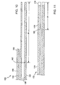
FIG 11 is a cross-section of a balloon catheter. - Like reference symbols in the various drawings indicate like elements.
- Referring to
FIG 1A , aballoon catheter 2 includes aproximal portion 4, and a distal portion that has aflexible body 6 and aninflatable balloon 8. Theproximal portion 4, which remains outside the patient, includes aguide wire port 5 and an inflation fluid port 7. Referring particularly toFIGS. 1B and 1C , thecatheter 2 has a coaxial design including aninner tube 10 and a coaxially arrangedouter tube 12. Theinner tube 10 defines between a proximal opening 7 and a distal opening 9, alumen 11 which extends the length of thetube 10 so that the catheter can be delivered over a guide wire. Theinner tube 10 has aproximal section 15, a seconddistal section 16, and atransition 17 between the sections. The flexibility of the sections and the position, P, of the transition between the sections is selected to enhance deliverability of the catheter, as will be described in detail below. - The
outer tube 12 extends from the proximal end to theballoon 8. Alumen 13 is defined between theinner tube 10 and theouter tube 12 through which inflation fluid can be delivered (arrows 14). Theballoon 8 is attached at its proximal end to theouter tube 12 and at its distal end to theinner tube 10. Referring toFIG 1D , prior to delivery into a body lumen, theballoon 8 is typically maintained in a low-profile configuration by tightly wrapping theballoon 8 around the inner tube in a series of overlapping wings or folds 24. - In embodiments, the distal portion of the catheter has a length of about, e.g., 60 to 140 cm. The balloon has an inflated diameter of about 1.5 to 10 mm, a length of about 8 to 40 mm and can include a relatively stiff, noncompliant material such as a biaxially oriented polymer, e.g. PET or nylon. The balloon can also be formed of compliant or semi-compliant materials such as PEBAX, available from Atofina, Philadelphia, PA, as an example. The outer tube is a relatively stiff, burst-resistant polymer such as polyamide-12. Typically, the catheter inner tube has an overall length of about 25 cm to 140 cm, but can be longer or shorter depending on the application. For example, in coronary applications, the catheter typically has an overall length sufficient to be delivered femorally, via the femoral artery, or brachially, via the brachial artery. The catheter can also be delivered peripherally, for example, via the radial artery. For vascular applications, the length is typically about 135 to 140 cm. The catheter can be a rapid exchange type catheter in which the guidewire exits the guidewire lumen distal of the
proximal portion 4. - Referring to
FIG 2A , thecatheter 2 is delivered into abody lumen 22 over aguide wire 18. The catheter may be delivered through anintroducer 26, also positioned in the lumen. The exit of the introducer may be positioned at a point proximal of a region of lumen tortuosity or reduced diameter, e.g., in the coronary artery. Thecatheter 2 is extended from the end of the introducer to position the balloon at a treatment site where the balloon is inflated to dilate the lumen. For example, in coronary applications, the distal end of the catheter typically extends from about 1 to 15 cm from the end of the introducer in delivering the balloon to the treatment site. - Referring also to
FIG 2A , as the catheter is urged through thebody lumen 22,balloon 8 becomes partially unfolded thus increasing the diametric profile ofballoon 8 and also modifying the flexibility profile of the catheter. In particular, when the balloon is tightly wrapped about a catheter (FIG 1D ), the stiffness of the distal portion of the catheter is largely influenced, or even dominated, by the balloon. However, as the catheter is delivered into the body through the introducer, and particularly as the distal portion of the catheter extends beyond the introducer, the balloon wrapping loosens, as illustrated inFIG 2A . The mechanical characteristics of the catheter becomes increasingly influenced, even largely dominated, by the inner tubular member. When the catheter is used to deliver a stent, the stent is slipped over the balloon after the balloon has been tightly wrapped about the catheter body. The stent can be held in place by partially inflating the balloon, which loosens the wrapped configuration of the balloon. - The catheter deliverability is enhanced by selecting in combination the relative buckling strength of the proximal and distal sections of the inner tube and the location of the transition between the sections. The buckling strength of the proximal and distal sections can be determined by measuring the column strength and/or flexural modulus of the sections. The position of the transition is measured from the distal end. The buckling strength differences and position of the transition are selected to balance the catheter pushability and trackability. Pushability is the capability to transmit to the distal end of the catheter an axial or rotational force imposed on the proximal end of the catheter. Trackability is the capability to pass a torturous passageway. Trackability is generally facilitated by a more flexible catheter but too much lateral flexibility can lead to problems such as buckling as the catheter is directed around a sharp curvature.
- In a typical application, the performance requirements for deliverability become more severe as the catheter is urged more deeply into a vessel. Greater pushability is required since the distance between the more proximal portion, which is grasped by the physician, and the distal end increases. At the same time, in more remote portions of the vessel, the vessel diameter typically narrows and the vessel becomes more tortuous, thus greater trackability is also desirable.
- In embodiments, the column strength and/or flexural modulus of the distal section is about 75% or less, e.g. 40%-20%, than the column strength and/or flexural modulus of the proximal section. The transition is located from the distal end at a position corresponding to about 20% or less, e.g. 10% or 5% or less, than the overall length of the tube. In embodiments, the column strength (measured per 2.54 cm length) of the proximal section is in the range of about 1 to 20 g, e.g., about 2 to 17 g. In embodiments, the column strength (measured per 2.54 cm length) of the distal section is in the range of about 2-7 g and the column strength of the proximal portion is in the range of about 9 to 16 g. In embodiments, the transition is about 1 to 10 cm, e.g., 1.5 to 9 cm, 3 to 8 cm, 4 to 7.5 cm, or 7cm or less from the distal end of the catheter. The position of the transition can be varied depending on the length of the balloon. The transition is typically under or proximal of the balloon. For a longer balloon, the transition position is generally further from the distal end of the catheter. The transition is typically not so far proximal of the balloon that the unwrapped balloon does not influence the stiffness of substantially the length of the distal section. For example, the transition is typically within about 5 cm or 2 cm or less of the most proximal inflated portion of the balloon. (The most proximal inflated portion is distal of the region where the balloon is attached to the catheter.) In addition, the location of the transition can be selected such that the transition does not substantially extend beyond an introducer. A catheter and introducer can be provided as a kit such that the transition permits a range of catheter extensions without the transition extending beyond the introducer.
- Referring particularly to
FIG. 3 , in an embodiment, aninner tube 50 includes multiple polymer layers to enhance deliverability and other characteristics. Theinner tube 50 includesproximal section 52,distal section 54, andtransition 56 selected to enhance delivery through a tortuous lumen. In this example, both sections include multiple, in this case three, layers. Theproximal section 52 has an innermost (or inside)layer 36, amiddle layer 38, and anouter layer 40. The distal section has aninside layer 42, amiddle layer 44, and anouter layer 46. In both the proximal and distal portions, the inside layers 36, 42 are formed of high radial strength, hard, low-friction polymer that resists collapse during balloon inflation and facilitates movement of the catheter over a guide wire. Suitable polymers include high density polyethylenes, fluoropolymers such as ethylene tetrafluoro ethylene, or graphite-filled nylons. A particular high density polyethylene example is Marlex 4903, available from Chevron Phillips. The middle layers 38, 44 are tie layers that facilitate bonding between the inner and outer layers. Suitable polymers include maleic anhyride functionalized linear low-density polyethylenes. A particular example is Plexar PX-380, available from Equistar, Houston, TX. - The
outer layers outer layer 40 in the proximal section is typically a stiffer material than theouter layer 46 of thedistal section 16. Thelayers transition 56 at a position, P, from the distal end of the tube. In embodiments, the flexural modulus of thelayer 46 is about 75% or less than the flexural modulus of thelayer 40. In embodiments, the flexural modulus of thelayer 46 is about 15 to 500 MPa and the flexural modulus of thelayer 40 is about 700 to 4000 MPa. Suitable polymers include elastomers, such as thermoplastic elastomers. Examples include nylons such asnylon 12. In a particular example, the proximalouter layer 40 is a blend of 60% TR55LXamorphous polyamide 12 available from EMS, Switzerland (flexural modulus of 2000 MPa) and 40% L20 polyamide 12 also available from EMS, Switzerland (flexural modulus of 1100 MPa). The flexural modulus of the blend is about 1600 MPa. The distalouter layer 46 is a blend of 75% Pebax 7033 available from Atofina, Philadelphia, PA (flexural modulus of 465 MPa) and 25% Pebax 5533 available from Atofina, Philadelphia, PA (flexural modulus of 201 MPa). The flexural modulus of the blend is about 400 MPa. The tube can be manufactured by separately coextruding tube elements for the proximal and distal portions, cutting the tube elements to desired lengths, and bonding the tube elements by comelting with a laser. - Referring to
FIG. 4 in another embodiment, a multilayerinner tube 60 is made by a continuous coextrusion process that defines a tube of substantially constant diameter. Thetube 60 includes aproximal section 62 and adistal section 64 having three layers. Insidelayer 66 is made of material that provides low friction between theinside layer 66 and a guide wire (not shown) as the catheter tracks along the guide wire within the body lumen.Middle layer 68 is a bonding agent, bonding theinside layer 66 and anouter layer 70. The outer layer is selected to alter flexibility relative to atransition region 72. The inner and middle layers are generally of constant thickness. - The outer layer is composed of two
sublayers layer 73 is relatively thin and thelayer 75 is relatively thick. In the distal section,layer 73 is relatively thin and thelayer 75 is relatively thick. The column strength or flexural modulus of the materials inlayers transition 72 can be varied. For example, in the example illustrated, the material inlayer 73 may have a greater flexural modulus than the material inlayer 75. In this arrangement thetransition 72 has a transition length t1, over which the thickness ofsublayers WO 01/32398A1 - Referring now to
FIG. 5 , in another embodiment, atube 80 has proximal and distal sections of different dimensions.Tube 80 has aproximal section 88, adistal section 90, and a transition 92. The tube portions have three layers with aninside layer 82 of a constant material and constant cross section.Middle layer 84 is a bonding layer, also of constant material and constant cross section.Middle layer 84 bonds theinside layer 82 and acover layer 86. The outer diameter from the larger outer diameterproximal section 88 tapers to the smaller diameterdistal section 90. The transition 92 has a transition length tL where the thickness of the tube varies. The tube is formed by coextrusion. The diametric variation is formed by varying the puller speed during coextrusion. This varying of puller speed creates a transition region 92 where the larger outer diameter of theproximal section 88 tapers to the smaller outer diameter of thedistal section 90. - Column strength can be measured by investigating load before buckling. Referring to
FIG. 6 , anInstron 100 is used, having a 50 N load cell traveling at 2,54 cm (1 inch) per minute, to measure the buckling strength of a 2.54 cm 1-inchlong tude sample 110. The column strength is taken as the peak load measured prior to buckling. A suitable instrument is aBionix® 100, available from MTS Systems Corporation. The flexural modulus, which represents the ratio of stress to strain as a material is deformed under dynamic load, can be measured by ASTM method D790. - Referring to
Fig. 7 , deliverability comparisons of catheters can be made using a test assembly that has atortuous path 124 defined by a polymer tube. Forces on the catheter and the tube can be measured by a series oftransducers transducer 126 by threading the catheter through the path such that the distal end abuts the transducer. As a force is imposed on a proximal portion of the catheter by a pair ofdrive wheels 122, thetransducer 126 measures the amount of force that is transferred from the proximal to the distal end. Track force is measured bytransducer 127 as a function of catheter location along the path as the catheter is driven through the path at a constant rate. Thetransducer 127 measures the deflection of a base 1.29 from which the tube is cantilevered. By measuring the deflection of the base, the force on the path as the catheter is threaded along can be determined. Input force is the force measured bytransducer 131.Transducer 131 measures the force required to drive the catheter along the path at a constant rate as a function of distance of catheter travel. The track force data and input force data can be integrated to determine the total work required to deliver samples along the path. - A
suitable path 124 is defined in a tube element made of Teflon™, which has an inner diameter of 0,198 cm (0.074 inch) and a wall thickness of 0,015 cm (0.006 inch). The path has an overall length of about 33,65 cm (13.25 inch). The path has a firststraight leg 125 of 28,58 cm (11.25 inch), a 3,81 cm (1.5 inch) diametersemicircular bend 128 and a secondstraight leg 130 of 1,27 cm (0.5 inch). A 0,036 cm (0.014 inch) diameter guide wire is positioned in the path. Atortuous path 124 mimics the path found in the coronary arteries. Entrance of a test sample into thetortuous path 124 simulates the exiting of the distal end of the catheter from the introducer into the path defined by the exposed artery (seeFig. 2A ). The path is immersed in a water bath at 37°C. A suitable drive speed is about 20 cm/min. - Referring to Table I, column strength and push response data for several tube samples is provided.
Table I Sample Tube Design Transition Position Column Strength Push response 1 Polyamide - 13g MA/PE - PE 2 Pebax blend - 4.5 g MA/PE - PE 3 1/2 5 cm - 23 g/ cm 4 1/2 7 cm - 19 g/ cm 5 Pebax - 5.7 g 19 g/cm MA/ PE PE 6 Polyamide - 8.4 g MA/PE PE - (0.0235 in) 7 Polyamine - 5.9 g - MA/PE PE (0.022inch) 8 6/7 5 cm - 24 g/cm - In
Samples amorphous polyamide % L20 polyamide 12. The distal section of the outer layer is a pellet mixed blend of 75% Pebax 7033 and 25 % Pebax 5533. After forming the proximal and distal three-layer sections, each is tested to determine their respective column strengths. As the table indicates, the column strength of the distal section (Sample 2) was about 35% of the column strength of the proximal section (Sample 1). - In
Sample 3, a two section tube is prepared by laser welding squared ends of the proximal and distal sections described inSamples Sample 3 has a push response of about 23 g/cm. InSample 4, the tube structure is the same as inSample 3 but the transition is at 7 cm. The push response is about 19 g/cm. - In
Sample 5, an inner tube is formed by constant coextrusion with no transition (i.e., the inner tube is monolithic). The outer layer of the tube is Pebax 7233 and the middle layer and inside layer are Plexar PX-380 and Marlex 4903, respectively. The column strength is 5.7 g, intermediate between the proximal and distal portions inSamples Sample 5, the push strength is 19 g/cm, which is about 18% less than the push strength ofSample 3. Thus,bi-component Sample 3 exhibits an improved push strength, relative tomonolithic Sample 5. - In Samples 6-8, tubes having varying dimensions are investigated. In
Sample 6, a monolithic tube component is extruded to have three layers. The outer layer isL20 polyamide 12 and the inside and middle layers are Marlex 4903 and Plexar PX-380, respectively. Sample 7 is also a monolithic tube component formed of an outer layer orL20 polyamide 12, a middle layer of Plexar PX-380 and an inside layer of Marlex 4903. Each of the layers of theSamples 6 and 7 are of constant wall thickness, but the outer diameter of Sample 7 is less than the outer diameter ofSample 6.Sample 6 has an outer diameter of 0,060 cm (0.0235 inch) and Sample 7 has an outer diameter of 0,053 cm (0.021 inch). The column strength ofSample 6 is 8.4 g and the column strength of Sample 7 is 5.9 g. -
Sample 8 combinesSamples 6 and 7 by tapering the outer layer ofL20 polyamide 12, from the proximal outer diameter of 0,060 cm (0.0235 inch) to a smaller distal diameter of 0,053 cm (0.021 inch) a position (P) 5 cm from the distal end. The outer layer diameter is tapered by varying the puller speed during coextrusion. The inner tubular member is tested as outlined above. As the data indicates,Sample 8 exhibits a push response of about 24 g/cm. - Referring now to Table II, track work data is provided for a series of coaxial catheters using inner tubes of different designs.
Table II Sample Inner Tube Design Transition Location Track Work (g-cm) Monolithic Sample 1Pebax 7233 (outer) none 121.2 MA/PE (middle) PE (inside) Bi-component Sample 1Polyamide (proximal outer) 7 cm 99.9 Pebax blend (distal outer) MA/PE (middle) PE (inside) Bi-component Sample 2Pebax 7233 (proximal outer) 7 cm 93.2 Pebax 63D (distal outer) MA/PE (middle) PE (inside) Bi-component Sample 3Pebax 7233 (proximal outer) 7 cm 95.3 Pebax 66D (distal outer) MA/PE (middle) PE (inside) - To obtain comparative track, the inner tube designs were combined with an outer tube and balloon of common design to provide a catheter assembly. The outer tube included a hypotube of stainless steel that has a length of about 101,6 cm (40 inches), an inner diameter of about 0,048 cm (0.019 inch) and an outer diameter of about 0,058 cm (0.023 inch). Laser welded to the distal end of the hypotube is a second tubular section. The second tubular section is made of Pebax 72D, which extends about 38,10 cm (15 inches) and has an outer diameter of about 0,813 cm (0.032 inch) and has an inner diameter of about 0,066 cm (0.026 inch). The balloon is attached at the distal end at the second tubular section.
-
Monolithic Sample 1 is a catheter assembly including an inner tube that is a monolithic, three layer extrusion including Pebax 7233 as the outer layer, Marlex 4903 as the middle layer and Plexar PX-380 as the inside layer. -
Bi-Component Sample 1 includes an inner tube that has three layers and proximal and distal sections. The proximal section has an inside layer ofPE (Marlex 4903), a middle layer of Plexar PX-380 and a outer layer (proximal outer) of a pellet mixed blend of 60 % TR55LXamorphous polyamide % L20 polyamide 12. The distal section includes an inside layer of PE (Marlex 4903), a middle layer of Plexar PX-380 and a outer layer (distal outer) of a pellet mixed blend of 75% Pebax 7033 and 25 % Pebax 5533. The proximal and distal sections are joined by welding. -
Bi-Component Sample 2 has three layers and a proximal and distal section. Inside and middle layers are formed of Marlex 4903 and Plexar PX-380, respectively. The outer layer in the proximal section (proximal outer) is Pebax 7233. The outer layer in the distal section is Pebax 63D. -
Bi-Component Sample 3 has three layers and a proximal and distal section. Inside and middle layers are formed of Marlex 4903 and Plexar PX-380, respectively. The outer layer in the proximal section (proximal outer) is Pebax 7233. The outer layer in the distal section is Pebax 66D. The transition region of each of the three bi-component samples is located 7 cm from the distal end. - As the data indicates, the bi-component samples required substantially less work, and hence improved trackability compared to the monolithic samples. In addition,
Bi-component Sample 1, which corresponds toSample 4 in Table I, illustrates improved trackability while maintaining push response of certain monolithic samples, translating to improved deliverability. - Referring now to
Fig. 8 , a graph of track force as a function of distance, indicating deliverability, is provided for the assemblies in Table II. The average force per unit distance is less for the bi-component assemblies compared to the monolithic assemblies. For the bi-component samples, the proximal section begins to track through the tortuous path at 7 cm. However, the bi-component samples continue to exhibit improved deliverability relative to the monolithic samples, even beyond 7 cm. - Referring now to Table III, data for catheter assemblies with bi-component samples having inner tubes having different transition locations is provided.
Table III Sample Tube Design Transition Location Input Work (g-cm) Sample A Polyamide (proximal outer) 7 cm 271 Pebax blend (distal outer) MA/PE (middle) PE (inside) Sample B Polyamide (proximal outer) 2.5 cm 291.4 Pebax blend (distal outer) MA/PE (middle) PE (inside) Sample C Polyamide (proximal outer) 1 cm 298.6 Pebax blend (distal outer) MA/PE (middle) PE (inside) - The inner tube has proximal and distal sections composed as described above in
Bi-Component Sample 1 of Table II. Sample A has a transition location 7 cm from the distal end, Sample B has a 2.5 cm transition location and Sample C has a 1 cm transition location. As the data indicates, Sample A, having a 7 cm transition location, required substantially less input work to traverse the test path compared to bi-component samples having 1 cm and 2.5 cm transition locations. - Referring as well to
Fig. 9 , a plot of input force as a function of the path distance for catheter assemblies in Table III is provided. As the graph indicates, Sample A provides substantially improved trackability at longer path distances. - Referring to
FIG 10 , acatheter 150 having abody 152 defining side by side lumens is illustrated. Afirst lumen 154 extends substantially the length of the catheter for use in guide wire delivery. Asecond lumen 156 provides inflation fluid to the balloon. Thebody 152 has aproximal portion 158, adistal portion 160 and atransition 162 at a position P from the distal end of the tube. The proximal and distal portions can be formed of different materials and/or different cross-sectional dimensions to vary the flexibility of the portions about the transition as discussed above. The proximal and distal portions can include multiple polymer layers as described above. - Referring to
FIG 11 , in another embodiment, acatheter body 172 having more than two sections, in thiscase sections transition 180 betweenfirst sections first section 176 may have a relatively high flexural modulus and the second section may have a relatively low flexural modulus. Thesection 178 may include a radiopaque material such as a metal to facilitate monitoring the catheter by fluoroscopy. Thesection 178 may also be made of a very soft polymer with a relatively small diameter to provide an atraumetic distal tip. Thesection 178 can be positioned distal of the balloon. In other embodiments, theproximal section 174 can be composed of multiple subsections of different column strengths, composition and/or diameter. - In further embodiments, the catheter body is a rapid-exchange type catheter body which includes a pathway for the guide wire to exit at a location distal to the proximal end and proximal of the balloon. In further embodiments, the balloon catheter can be arranged for use in non-vascular applications such as the esophagus, the gastrointestinal tract, or the urinary tract.
Claims (19)
- A concentric balloon catheter (2), comprising a polymeric outer tubular member (12), including a balloon (8), and a polymeric inner tubular member (50; 60; 80) located within a lumen (13) of the outer tubular member (12), the inner tubular member (50; 60; 80) having a first, proximal section (52; 62; 88) with a distal end welded to a proximal end of a second more distal section (54; 64; 90) to define a transition (56; 72), the inner tubular member (50; 60; 80) comprising three or more layers in each of the first and second sections,
the second section (54; 64; 90) having a column strength of 75 percent or less than the column strength of the first section (52; 62; 88), the transition (56; 72) located one to ten centimeters from the distal end of the inner tubular member (50; 60; 80). - The catheter (2) of claim 1 wherein the transition (56; 72) is four to seven centimeters from the distal end of the inner tubular member (50; 60; 80).
- The catheter (2) of claim 1 or 2 wherein the first section (52; 62; 88) has a column strength, per 2.54 centimeters, of five grams to 20 grams and the second section (54; 64; 90) has a column strength, per 2.54 centimeters, of two grams to seven grams.
- The catheter (2) of one of claims 1 to 3 wherein the transition (56; 72) is located proximal of the balloon (8).
- The catheter (2) of one of claims 1 to 4 wherein the inner tubular member (50; 60; 80) has a push strength of 15 g/cm or more.
- The catheter (2) of one of claims 1 to 5 wherein the transition (56) is at a joint (56) between the first (52) and second (54) tube sections.
- The catheter (2) of one of claims 1 to 6 wherein the transition (56; 72; 92) has a region (72) of varying flexibility.
- The catheter (2) of claim 7 wherein the region (72) of varying flexibility is formed by a thickness variation of a first polymer (73) and a second polymer (75).
- The catheter (2) of claim 7 wherein the region of varying flexibility is formed by a variation in diameter (86) of the tubular member (80).
- The catheter (2) of one of claims 1 to 9 wherein the first (88) and second (90) sections have different diameters.
- The catheter (2) of claim 10 wherein the first (52; 62; 88) and second (54; 64; 90) sections have the same polymer composition.
- The catheter (2) of one of claims 1 to 9 wherein the first (2; 62; 88) and second (54; 64; 90) sections have different polymer compositions.
- The catheter (2) of one of claims 1 to 12 wherein the first (62; 88) and second (64; 90) sections have the same innermost layer (66; 82).
- The catheter (2) of one of claims 1 to 13 wherein a second layer (40; 46; 70; 86) in both the proximal (52; 62; 88) and distal (54; 64; 90) sections is elastomeric.
- The catheter (2) of claim 14 wherein the second layers (40; 46; 70; 86) in the proximal (52; 62; 88) and distal (54; 64; 90) sections have different durometers.
- The catheter (2) of claim 15 including a bonding layer (38; 44; 68; 84) between the innermost (36; 42; 66; 82) and second layers (40; 46; 70; 86).
- The catheter (2) of one of claims 1 to 16 comprising a vascular angioplasty catheter.
- The catheter (2) of one of claims 1 to 17 wherein the balloon (8) is a substantially nondistenable polymer.
- The concentric balloon catheter (2) of one of claims 1 to 18, wherein the inner tubular member (50;60;80) has a substantially constant outer diameter along its length.
Applications Claiming Priority (3)
| Application Number | Priority Date | Filing Date | Title |
|---|---|---|---|
| US45025503P | 2003-02-26 | 2003-02-26 | |
| US450255P | 2003-02-26 | ||
| PCT/US2004/005722 WO2004075952A2 (en) | 2003-02-26 | 2004-02-26 | Balloon catheter |
Publications (2)
| Publication Number | Publication Date |
|---|---|
| EP1596898A2 EP1596898A2 (en) | 2005-11-23 |
| EP1596898B1 true EP1596898B1 (en) | 2009-04-08 |
Family
ID=32927624
Family Applications (1)
| Application Number | Title | Priority Date | Filing Date |
|---|---|---|---|
| EP04715085A Expired - Lifetime EP1596898B1 (en) | 2003-02-26 | 2004-02-26 | Balloon catheter |
Country Status (8)
| Country | Link |
|---|---|
| US (1) | US7163523B2 (en) |
| EP (1) | EP1596898B1 (en) |
| JP (1) | JP4575361B2 (en) |
| AT (1) | ATE427763T1 (en) |
| CA (1) | CA2516986C (en) |
| DE (1) | DE602004020449D1 (en) |
| ES (1) | ES2325398T3 (en) |
| WO (1) | WO2004075952A2 (en) |
Families Citing this family (86)
| Publication number | Priority date | Publication date | Assignee | Title |
|---|---|---|---|---|
| US6863678B2 (en) | 2001-09-19 | 2005-03-08 | Advanced Cardiovascular Systems, Inc. | Catheter with a multilayered shaft section having a polyimide layer |
| US7025745B2 (en) * | 2002-10-07 | 2006-04-11 | Advanced Cardiovascular Systems, Inc. | Method of making a catheter balloon using a tapered mandrel |
| US20050256562A1 (en) * | 2004-05-14 | 2005-11-17 | Boston Scientific Scimed, Inc. | Stent delivery handle and assembly formed therewith |
| US8500797B2 (en) * | 2004-09-08 | 2013-08-06 | Boston Scientific Scimed, Inc. | Medical devices |
| US7722578B2 (en) * | 2004-09-08 | 2010-05-25 | Boston Scientific Scimed, Inc. | Medical devices |
| JP4780678B2 (en) * | 2004-09-24 | 2011-09-28 | ライトラボ・イメージング・インコーポレーテッド | Body fluid blocking device |
| ATE501687T1 (en) * | 2004-09-28 | 2011-04-15 | Cordis Corp | MEDICAL THIN FILM DEVICE AND DELIVERY SYSTEM |
| US7951116B2 (en) * | 2004-11-12 | 2011-05-31 | Boston Scientific Scimed, Inc. | Selective surface modification of catheter tubing |
| US9480589B2 (en) * | 2005-05-13 | 2016-11-01 | Boston Scientific Scimed, Inc. | Endoprosthesis delivery system |
| EP1892007B1 (en) * | 2005-06-14 | 2011-10-26 | Vayu Co., Ltd | Balloon catheter |
| US9526814B2 (en) * | 2006-02-16 | 2016-12-27 | Boston Scientific Scimed, Inc. | Medical balloons and methods of making the same |
| US20070191931A1 (en) * | 2006-02-16 | 2007-08-16 | Jan Weber | Bioerodible endoprostheses and methods of making the same |
| US7678223B2 (en) | 2006-04-17 | 2010-03-16 | Boston Scientific Scimed, Inc. | Catheter having a multi-section tubular member and method of making the same |
| US7718106B2 (en) * | 2006-05-30 | 2010-05-18 | Boston Scientific Scimed, Inc. | Medical devices and related systems and methods |
| US9307995B2 (en) * | 2006-06-15 | 2016-04-12 | Cook Medical Technologies Llc | Methods, systems and devices for the delivery of endoluminal prostheses |
| US8382738B2 (en) | 2006-06-30 | 2013-02-26 | Abbott Cardiovascular Systems, Inc. | Balloon catheter tapered shaft having high strength and flexibility and method of making same |
| US7906066B2 (en) * | 2006-06-30 | 2011-03-15 | Abbott Cardiovascular Systems, Inc. | Method of making a balloon catheter shaft having high strength and flexibility |
| US10004584B2 (en) | 2006-07-10 | 2018-06-26 | First Quality Hygienic, Inc. | Resilient intravaginal device |
| US8613698B2 (en) | 2006-07-10 | 2013-12-24 | Mcneil-Ppc, Inc. | Resilient device |
| AU2007272601B2 (en) | 2006-07-10 | 2014-01-16 | First Quality Hygienic, Inc. | Resilient device |
| US8047980B2 (en) | 2006-07-10 | 2011-11-01 | Mcneil-Ppc, Inc. | Method of treating urinary incontinence |
| US10219884B2 (en) | 2006-07-10 | 2019-03-05 | First Quality Hygienic, Inc. | Resilient device |
| CA2659281A1 (en) * | 2006-07-28 | 2008-01-31 | Taylor Medical, Inc. | Catheter components formed of a compound of polymer with particles or fibers |
| WO2008034048A2 (en) | 2006-09-15 | 2008-03-20 | Boston Scientific Limited | Bioerodible endoprosthesis with biostable inorganic layers |
| US9387308B2 (en) | 2007-04-23 | 2016-07-12 | Cardioguidance Biomedical, Llc | Guidewire with adjustable stiffness |
| AU2008244613A1 (en) * | 2007-04-23 | 2008-11-06 | Intervention & Surgical Innovations, Llc | Guidewire with adjustable stiffness |
| US8403885B2 (en) | 2007-12-17 | 2013-03-26 | Abbott Cardiovascular Systems Inc. | Catheter having transitioning shaft segments |
| EP2689789B1 (en) | 2008-03-28 | 2019-03-13 | SurModics, Inc. | Insertable medical devices having microparticulate-associated elastic substrates and methods for drug delivery |
| US9364349B2 (en) | 2008-04-24 | 2016-06-14 | Surmodics, Inc. | Coating application system with shaped mandrel |
| JP2010000299A (en) * | 2008-06-23 | 2010-01-07 | Fujinon Corp | Flexible tube for endoscope and endoscope |
| US8052638B2 (en) | 2008-11-26 | 2011-11-08 | Abbott Cardiovascular Systems, Inc. | Robust multi-layer balloon |
| US8444608B2 (en) | 2008-11-26 | 2013-05-21 | Abbott Cardivascular Systems, Inc. | Robust catheter tubing |
| US8725228B2 (en) * | 2009-02-20 | 2014-05-13 | Boston Scientific Scimed, Inc. | Steerable catheter having intermediate stiffness transition zone |
| JP5814913B2 (en) | 2009-04-28 | 2015-11-17 | サーモディクス,インコーポレイテッド | Bioactive agent delivery device and delivery method |
| US20110238041A1 (en) * | 2010-03-24 | 2011-09-29 | Chestnut Medical Technologies, Inc. | Variable flexibility catheter |
| CA2803361C (en) | 2010-06-30 | 2020-07-21 | Surmodics, Inc. | Lipid coating for medical devices delivering bioactive agent |
| US10780251B2 (en) | 2010-09-17 | 2020-09-22 | W. L. Gore & Associates, Inc. | Expandable medical devices |
| US20120172796A1 (en) | 2010-12-30 | 2012-07-05 | Chappa Ralph A | Composition for intravascular delivery of therapeutic composition |
| US8668667B2 (en) | 2010-12-30 | 2014-03-11 | Surmodics, Inc. | Double wall catheter for delivering therapeutic agent |
| US8652098B2 (en) * | 2011-03-08 | 2014-02-18 | Abbott Cardiovascular Systems Inc. | Catheter with radiopaque coil |
| WO2012148745A1 (en) * | 2011-04-25 | 2012-11-01 | St. Jude Medical Puerto Rico Llc | Distal balloon bond for temporary sealing location device and methods |
| US10213529B2 (en) | 2011-05-20 | 2019-02-26 | Surmodics, Inc. | Delivery of coated hydrophobic active agent particles |
| US9861727B2 (en) | 2011-05-20 | 2018-01-09 | Surmodics, Inc. | Delivery of hydrophobic active agent particles |
| CN107007921B (en) | 2011-05-26 | 2020-01-21 | 雅培心血管系统有限公司 | Through tip of catheter |
| AU2012276660B2 (en) | 2011-06-29 | 2016-08-11 | Terumo Kabushiki Kaisha | Sheath for introducer |
| US9370647B2 (en) | 2011-07-14 | 2016-06-21 | W. L. Gore & Associates, Inc. | Expandable medical devices |
| US8945145B2 (en) * | 2011-09-22 | 2015-02-03 | Medtronic, Inc. | Delivery system assemblies for implantable medical devices |
| US8945146B2 (en) | 2011-10-24 | 2015-02-03 | Medtronic, Inc. | Delivery system assemblies and associated methods for implantable medical devices |
| US9216293B2 (en) | 2011-11-17 | 2015-12-22 | Medtronic, Inc. | Delivery system assemblies for implantable medical devices |
| US8721587B2 (en) | 2011-11-17 | 2014-05-13 | Medtronic, Inc. | Delivery system assemblies and associated methods for implantable medical devices |
| CN104185661B (en) | 2012-01-18 | 2016-08-17 | 苏尔莫迪克斯公司 | The lubricity medical treatment device coating of low microgranule |
| US9072624B2 (en) | 2012-02-23 | 2015-07-07 | Covidien Lp | Luminal stenting |
| MX351261B (en) | 2012-06-01 | 2017-10-06 | Surmodics Inc | Apparatus and method for coating balloon catheters. |
| US9827401B2 (en) | 2012-06-01 | 2017-11-28 | Surmodics, Inc. | Apparatus and methods for coating medical devices |
| US8684963B2 (en) | 2012-07-05 | 2014-04-01 | Abbott Cardiovascular Systems Inc. | Catheter with a dual lumen monolithic shaft |
| WO2014066760A1 (en) | 2012-10-25 | 2014-05-01 | Surmodics, Inc. | Apparatus and methods for coating medical devices |
| US11090468B2 (en) | 2012-10-25 | 2021-08-17 | Surmodics, Inc. | Apparatus and methods for coating medical devices |
| WO2014071387A1 (en) | 2012-11-05 | 2014-05-08 | Surmodics, Inc. | Composition and method for delivery of hydrophobic active agents |
| US11246963B2 (en) | 2012-11-05 | 2022-02-15 | Surmodics, Inc. | Compositions and methods for delivery of hydrophobic active agents |
| US9283350B2 (en) | 2012-12-07 | 2016-03-15 | Surmodics, Inc. | Coating apparatus and methods |
| US11000632B2 (en) | 2013-01-04 | 2021-05-11 | Surmodics, Inc. | Low particulate lubricious coating with vinyl pyrrolidone and acidic polymer-containing layers |
| EP3549679A1 (en) | 2013-05-07 | 2019-10-09 | SurModics, Inc. | Apparatus and methods for coating medical devices |
| US9782186B2 (en) | 2013-08-27 | 2017-10-10 | Covidien Lp | Vascular intervention system |
| US10045867B2 (en) | 2013-08-27 | 2018-08-14 | Covidien Lp | Delivery of medical devices |
| CA2871300A1 (en) * | 2013-11-29 | 2015-05-29 | Cook Medical Technologies Llc | Medical balloon |
| US10124088B2 (en) | 2014-09-29 | 2018-11-13 | Surmodics, Inc. | Lubricious medical device elements |
| CA2973625A1 (en) | 2015-01-14 | 2016-07-21 | Surmodics, Inc. | Insertion tools for medical device |
| EP3261707B1 (en) | 2015-02-26 | 2020-03-25 | SurModics, Inc. | Insertable medical device system with plaque treatment portion |
| US10478546B2 (en) | 2015-09-15 | 2019-11-19 | Surmodics, Inc. | Hemodialysis catheter sleeve |
| US11174447B2 (en) | 2015-12-29 | 2021-11-16 | Surmodics, Inc. | Lubricious coatings with surface salt groups |
| US10342898B2 (en) | 2015-12-29 | 2019-07-09 | Surmodics, Inc. | Lubricious coatings with surface salt groups |
| US10918835B2 (en) | 2016-03-31 | 2021-02-16 | Surmodics, Inc. | Delivery system for active agent coated balloon |
| EP3435988B1 (en) | 2016-03-31 | 2021-10-06 | Surmodics, Inc. | Drug-containing particulate composition with cationic agent, associated medical devices, and methods for treatment |
| US11712545B2 (en) | 2016-09-16 | 2023-08-01 | Surmodics, Inc. | Lubricious insertion tools for medical devices and methods for using |
| US11123459B2 (en) | 2016-12-16 | 2021-09-21 | Surmodics, Inc. | Hydrophobic active agent particle coatings and methods for treatment |
| US10898446B2 (en) | 2016-12-20 | 2021-01-26 | Surmodics, Inc. | Delivery of hydrophobic active agents from hydrophilic polyether block amide copolymer surfaces |
| US10376396B2 (en) | 2017-01-19 | 2019-08-13 | Covidien Lp | Coupling units for medical device delivery systems |
| US11413176B2 (en) | 2018-04-12 | 2022-08-16 | Covidien Lp | Medical device delivery |
| US11071637B2 (en) | 2018-04-12 | 2021-07-27 | Covidien Lp | Medical device delivery |
| US10786377B2 (en) | 2018-04-12 | 2020-09-29 | Covidien Lp | Medical device delivery |
| US11123209B2 (en) | 2018-04-12 | 2021-09-21 | Covidien Lp | Medical device delivery |
| WO2020112816A1 (en) | 2018-11-29 | 2020-06-04 | Surmodics, Inc. | Apparatus and methods for coating medical devices |
| US11819590B2 (en) | 2019-05-13 | 2023-11-21 | Surmodics, Inc. | Apparatus and methods for coating medical devices |
| US11413174B2 (en) | 2019-06-26 | 2022-08-16 | Covidien Lp | Core assembly for medical device delivery systems |
| US11478815B2 (en) | 2020-01-16 | 2022-10-25 | Surmodics, Inc. | Coating systems for medical devices |
| US11944558B2 (en) | 2021-08-05 | 2024-04-02 | Covidien Lp | Medical device delivery devices, systems, and methods |
Family Cites Families (124)
| Publication number | Priority date | Publication date | Assignee | Title |
|---|---|---|---|---|
| US3962519A (en) | 1968-04-26 | 1976-06-08 | Messrs. Willy Rusch, K.G. | Rubber article or instrument and method of producing the same |
| US3861972A (en) | 1970-08-24 | 1975-01-21 | Johnson & Johnson | Intravenous catheter |
| US3733309A (en) | 1970-11-30 | 1973-05-15 | Du Pont | Biaxially oriented poly(ethylene terephthalate)bottle |
| US3769984A (en) | 1971-03-11 | 1973-11-06 | Sherwood Medical Ind Inc | Pacing catheter with frictional fit lead attachment |
| US3745150A (en) | 1971-03-26 | 1973-07-10 | Du Pont | Amorphous polyethylene terephthalate container and process for making it |
| US3771527A (en) | 1971-08-16 | 1973-11-13 | J Ruisi | Surgical drainage tube |
| US3807408A (en) | 1972-01-17 | 1974-04-30 | D Summers | Retention catheter |
| US3837347A (en) | 1972-04-20 | 1974-09-24 | Electro Catheter Corp | Inflatable balloon-type pacing probe |
| US4035534A (en) | 1972-09-01 | 1977-07-12 | Raychem Corporation | Heat-shrinkable laminate |
| US3799172A (en) | 1972-09-25 | 1974-03-26 | R Szpur | Retention catheter |
| US3814137A (en) | 1973-01-26 | 1974-06-04 | Baxter Laboratories Inc | Injection site for flow conduits containing biological fluids |
| US3959426A (en) | 1973-06-29 | 1976-05-25 | Phillips Petroleum Company | Method of transferring and aligning parisons using clamping jaws with offset tines |
| US3833004A (en) | 1973-10-26 | 1974-09-03 | American Hospital Supply Corp | Balloon catheter having single ferrule support for balloon bindings |
| US3889685A (en) | 1973-11-02 | 1975-06-17 | Cutter Lab | Tubular unit with vessel engaging cuff structure |
| US3924634A (en) | 1974-09-11 | 1975-12-09 | Kendall & Co | Safety catheter and method |
| JPS5529809B2 (en) | 1974-10-08 | 1980-08-06 | ||
| US4079850A (en) | 1975-02-21 | 1978-03-21 | Toyo Seikan Kaisha Limited | Multi-layer blow molded container and process for preparation thereof |
| US3996938A (en) | 1975-07-10 | 1976-12-14 | Clark Iii William T | Expanding mesh catheter |
| US4047868A (en) | 1975-08-12 | 1977-09-13 | Toppan Printing Co., Ltd. | Multilayer parison extrusion molding machine for blow molding |
| US4085757A (en) | 1976-04-29 | 1978-04-25 | P Pevsner | Miniature balloon catheter method and apparatus |
| US4213461A (en) | 1977-09-15 | 1980-07-22 | Pevsner Paul H | Miniature balloon catheter |
| US4105022A (en) | 1976-05-24 | 1978-08-08 | Becton, Dickinson And Company | Method of determining cardiac output by thermodilution principles and utilization of a catheter assembly |
| US4140126A (en) | 1977-02-18 | 1979-02-20 | Choudhury M Hasan | Method for performing aneurysm repair |
| US4141364A (en) | 1977-03-18 | 1979-02-27 | Jorge Schultze | Expandable endotracheal or urethral tube |
| CH616337A5 (en) | 1977-10-21 | 1980-03-31 | Schneider Medintag Ag | |
| US4222384A (en) | 1977-11-09 | 1980-09-16 | Biomedical Engineering Associates, Inc. | Catheter |
| US4198981A (en) | 1978-03-27 | 1980-04-22 | Manfred Sinnreich | Intrauterine surgical device |
| US4233022A (en) | 1978-07-10 | 1980-11-11 | Owens-Illinois, Inc. | Apparatus for forming heat treated blown thermoplastic articles |
| US4250072A (en) | 1979-05-18 | 1981-02-10 | Flynn Vincent J | Radiopaque polyurethane resin compositions |
| JPS60126170A (en) * | 1983-12-14 | 1985-07-05 | テルモ株式会社 | Catheter and its production |
| US4627436A (en) | 1984-03-01 | 1986-12-09 | Innoventions Biomedical Inc. | Angioplasty catheter and method for use thereof |
| US4636346A (en) | 1984-03-08 | 1987-01-13 | Cordis Corporation | Preparing guiding catheter |
| US4597755A (en) | 1984-05-30 | 1986-07-01 | Advanced Cardiovascular Systems, Inc. | Large bore catheter having flexible tip construction |
| US4581390A (en) | 1984-06-29 | 1986-04-08 | Flynn Vincent J | Catheters comprising radiopaque polyurethane-silicone network resin compositions |
| US4637396A (en) | 1984-10-26 | 1987-01-20 | Cook, Incorporated | Balloon catheter |
| US4627844A (en) | 1985-10-30 | 1986-12-09 | High Voltage Engineering Corporation | Tri-layer tubing |
| US4921483A (en) | 1985-12-19 | 1990-05-01 | Leocor, Inc. | Angioplasty catheter |
| US4748982A (en) | 1987-01-06 | 1988-06-07 | Advanced Cardiovascular Systems, Inc. | Reinforced balloon dilatation catheter with slitted exchange sleeve and method |
| US4782834A (en) | 1987-01-06 | 1988-11-08 | Advanced Cardiovascular Systems, Inc. | Dual lumen dilatation catheter and method of manufacturing the same |
| US5358486A (en) * | 1987-01-09 | 1994-10-25 | C. R. Bard, Inc. | Multiple layer high strength balloon for dilatation catheter |
| US4776846A (en) | 1987-02-06 | 1988-10-11 | Becton, Dickinson And Company | Splittable catheter composite material and process |
| US5250069A (en) | 1987-02-27 | 1993-10-05 | Terumo Kabushiki Kaisha | Catheter equipped with expansible member and production method thereof |
| US4917667A (en) | 1988-02-11 | 1990-04-17 | Retroperfusion Systems, Inc. | Retroperfusion balloon catheter and method |
| US5188593A (en) | 1988-04-21 | 1993-02-23 | Vas-Cath Incorporated | Dual lumen catheter |
| US5499980A (en) * | 1988-08-08 | 1996-03-19 | Scimed Life Systems, Inc. | Polyimide balloon catheter and method of making same |
| US5304197A (en) | 1988-10-04 | 1994-04-19 | Cordis Corporation | Balloons for medical devices and fabrication thereof |
| US5223205A (en) | 1988-10-04 | 1993-06-29 | Cordis Corporation | Method for manufacturing balloons for medical devices |
| US5108415A (en) | 1988-10-04 | 1992-04-28 | Cordis Corporation | Balloons for medical devices and fabrication thereof |
| US5195972A (en) | 1988-10-28 | 1993-03-23 | Kanji Inoue | Balloon catheter assembly |
| MY104678A (en) | 1988-11-10 | 1994-05-31 | Bard Inc C R | Balloon dilatation catheter with integral guidewire. |
| JPH0820704B2 (en) | 1988-11-17 | 1996-03-04 | 富士写真フイルム株式会社 | Laminated film |
| US5160321A (en) | 1988-11-23 | 1992-11-03 | Harvinder Sahota | Balloon catheters |
| US5156857A (en) | 1988-11-23 | 1992-10-20 | American National Can Company | Extrusion die for extrusion blow molding equipment |
| CA1329091C (en) | 1989-01-31 | 1994-05-03 | Geoffrey S. Martin | Catheter with balloon retainer |
| DE69021607T2 (en) | 1989-03-10 | 1996-01-18 | Idemitsu Petrochemical Co | Process for the production of biaxially oriented nylon films. |
| US5137512A (en) | 1989-03-17 | 1992-08-11 | Scimed Life Systems, Inc. | Multisegment balloon protector for dilatation catheter |
| US5176697A (en) | 1989-04-06 | 1993-01-05 | Hasson Harrith M | Laparoscopic cannula |
| US5100381A (en) | 1989-11-13 | 1992-03-31 | Scimed Life Systems, Inc. | Angioplasty catheter |
| US5047045A (en) | 1989-04-13 | 1991-09-10 | Scimed Life Systems, Inc. | Multi-section coaxial angioplasty catheter |
| US5147302A (en) | 1989-04-21 | 1992-09-15 | Scimed Life Systems, Inc. | Method of shaping a balloon of a balloon catheter |
| IL90193A (en) | 1989-05-04 | 1993-02-21 | Biomedical Polymers Int | Polurethane-based polymeric materials and biomedical articles and pharmaceutical compositions utilizing the same |
| JP2545981B2 (en) | 1989-05-09 | 1996-10-23 | 東レ株式会社 | Balloon catheter |
| US5114423A (en) | 1989-05-15 | 1992-05-19 | Advanced Cardiovascular Systems, Inc. | Dilatation catheter assembly with heated balloon |
| US5312356A (en) | 1989-05-22 | 1994-05-17 | Target Therapeutics | Catheter with low-friction distal segment |
| US5116318A (en) | 1989-06-06 | 1992-05-26 | Cordis Corporation | Dilatation balloon within an elastic sleeve |
| US5272012A (en) | 1989-06-23 | 1993-12-21 | C. R. Bard, Inc. | Medical apparatus having protective, lubricious coating |
| US5759191A (en) * | 1989-06-27 | 1998-06-02 | C. R. Bard, Inc. | Coaxial PTCA catheter with anchor joint |
| US6179856B1 (en) * | 1989-07-05 | 2001-01-30 | Medtronic Ave, Inc. | Coaxial PTCA catheter with anchor joint |
| US5248305A (en) | 1989-08-04 | 1993-09-28 | Cordis Corporation | Extruded tubing and catheters having helical liquid crystal fibrils |
| US4976690A (en) | 1989-08-10 | 1990-12-11 | Scimed Life Systems, Inc. | Variable stiffness angioplasty catheter |
| US5318587A (en) | 1989-08-25 | 1994-06-07 | C. R. Bard, Inc. | Pleated balloon dilatation catheter and method of use |
| US5364357A (en) | 1989-09-25 | 1994-11-15 | Schneider (Usa) Inc. | Small diameter dilatation catheter having wire reinforced coaxial tubular body |
| DE69002295T2 (en) | 1989-09-25 | 1993-11-04 | Schneider Usa Inc | MULTILAYER EXTRUSION AS A METHOD FOR PRODUCING BALLOONS FOR VESSEL PLASTICS. |
| US5209728B1 (en) | 1989-11-02 | 1998-04-14 | Danforth Biomedical Inc | Low profile high performance interventional catheters |
| US5102416A (en) | 1989-11-21 | 1992-04-07 | Rock John M | Vessel vector invasive catheter |
| US5290306A (en) | 1989-11-29 | 1994-03-01 | Cordis Corporation | Puncture resistant balloon catheter |
| US5163949A (en) | 1990-03-02 | 1992-11-17 | Bonutti Peter M | Fluid operated retractors |
| US5179174A (en) | 1990-04-23 | 1993-01-12 | C. R. Bard, Inc. | Flexible lubricious organic coatings |
| US5125913A (en) | 1990-05-11 | 1992-06-30 | Fbk International Corporation | Soft-tipped catheters |
| US5279594A (en) | 1990-05-23 | 1994-01-18 | Jackson Richard R | Intubation devices with local anesthetic effect for medical use |
| US5279596A (en) | 1990-07-27 | 1994-01-18 | Cordis Corporation | Intravascular catheter with kink resistant tip |
| DE9106499U1 (en) | 1990-08-09 | 1991-07-25 | Schneider (Europe) Ag, Zuerich, Ch | |
| US5183613A (en) | 1990-08-22 | 1993-02-02 | Gencorp Inc. | Process for the preparation of solventless, low friction, abrasion-resistant coatings for elastomeric substrates |
| EP0476807A1 (en) | 1990-09-17 | 1992-03-25 | C.R. Bard, Inc. | Core wire steerable catheters |
| US5304171A (en) | 1990-10-18 | 1994-04-19 | Gregory Kenton W | Catheter devices and methods for delivering |
| DE69133523T2 (en) | 1990-11-09 | 2006-09-21 | Boston Scientific Corp., Watertown | Balloon for medical catheter |
| JP2555298B2 (en) | 1990-11-10 | 1996-11-20 | テルモ株式会社 | CATHETER BALLOON, CATHETER BALLOON MANUFACTURING METHOD, AND BALLOON CATHETER |
| US5263962A (en) | 1990-11-21 | 1993-11-23 | Johnson Medical Development Corp. | Balloon catheter and method of using the same |
| US5254091A (en) | 1991-01-08 | 1993-10-19 | Applied Medical Resources Corporation | Low profile balloon catheter and method for making same |
| US5254090A (en) | 1991-01-14 | 1993-10-19 | Kontron Instruments, Inc. | Balloon catheter having a dual layer inner member |
| US5108420A (en) | 1991-02-01 | 1992-04-28 | Temple University | Aperture occlusion device |
| US5171221A (en) | 1991-02-05 | 1992-12-15 | Target Therapeutics | Single lumen low profile valved balloon catheter |
| US5254107A (en) | 1991-03-06 | 1993-10-19 | Cordis Corporation | Catheter having extended braid reinforced transitional tip |
| US5195970A (en) | 1991-04-26 | 1993-03-23 | Gahara William J | Collapsible balloon catheters |
| US5195969A (en) | 1991-04-26 | 1993-03-23 | Boston Scientific Corporation | Co-extruded medical balloons and catheter using such balloons |
| US5330428A (en) | 1991-05-14 | 1994-07-19 | Scimed Life Systems, Inc. | Dilatation catheter having a random copolymer balloon |
| EP0549100A1 (en) | 1991-12-20 | 1993-06-30 | Interventional Technologies Inc | Catheter balloon formed from a polymeric composite |
| WO1993018816A1 (en) * | 1992-03-17 | 1993-09-30 | Scimed Life Systems, Inc. | Balloon dilatation catheter having a free core wire |
| US5304097A (en) * | 1993-01-19 | 1994-04-19 | Duff N R | Convertible, conventional or bumper, bowling lane |
| US5358493A (en) | 1993-02-18 | 1994-10-25 | Scimed Life Systems, Inc. | Vascular access catheter and methods for manufacture thereof |
| US5336205A (en) | 1993-02-25 | 1994-08-09 | Target Therapeutics, Inc. | Flow directed catheter |
| US5413559A (en) * | 1993-07-08 | 1995-05-09 | Sirhan; Motasim M. | Rapid exchange type over-the-wire catheter |
| DE69433506T2 (en) * | 1993-10-01 | 2004-06-24 | Boston Scientific Corp., Natick | MEDICAL, THERMOPLASTIC ELASTOMER CONTAINING BALLOONS |
| EP0744977B1 (en) * | 1993-11-12 | 2003-03-26 | Micro Interventional Systems | Small diameter, high torque catheter |
| US6406457B1 (en) * | 1994-03-02 | 2002-06-18 | Scimed Life Systems, Inc. | Block copolymer elastomer catheter balloons |
| US5533985A (en) * | 1994-04-20 | 1996-07-09 | Wang; James C. | Tubing |
| CA2347024C (en) * | 1994-04-20 | 2004-11-30 | James C. Wang | Method for making tubing |
| US5480383A (en) * | 1994-05-27 | 1996-01-02 | Advanced Cardiovascular Systems, Inc. | Dilation catheter with a smooth transition between a stiff proximal portion and a flexible distal portion |
| US5499973A (en) * | 1994-09-08 | 1996-03-19 | Saab; Mark A. | Variable stiffness balloon dilatation catheters |
| US5509899A (en) * | 1994-09-22 | 1996-04-23 | Boston Scientific Corp. | Medical device with lubricious coating |
| EP0794811B1 (en) * | 1994-11-23 | 2002-07-31 | Micro Interventional Systems, Inc. | High torque balloon catheter |
| US5658263A (en) * | 1995-05-18 | 1997-08-19 | Cordis Corporation | Multisegmented guiding catheter for use in medical catheter systems |
| JP3594971B2 (en) * | 1995-05-24 | 2004-12-02 | シュナイダー・(ユーエスエー)・インク | Inflatable balloon containing polyester ether amide copolymer |
| US5868704A (en) * | 1995-09-18 | 1999-02-09 | W. L. Gore & Associates, Inc. | Balloon catheter device |
| US6124007A (en) * | 1996-03-06 | 2000-09-26 | Scimed Life Systems Inc | Laminate catheter balloons with additive burst strength and methods for preparation of same |
| ATE327797T1 (en) * | 1996-04-26 | 2006-06-15 | Schneider Europ Gmbh | INTERVENTION CATHETER |
| US6048338A (en) * | 1997-10-15 | 2000-04-11 | Scimed Life Systems, Inc. | Catheter with spiral cut transition member |
| US6045547A (en) * | 1998-06-15 | 2000-04-04 | Scimed Life Systems, Inc. | Semi-continuous co-extruded catheter shaft |
| US6195969B1 (en) * | 1999-04-03 | 2001-03-06 | YILMAZ GüRSEL GEORGE | Apparatus for multifunctional lawn mower and multidirectional shell |
| WO2001032398A1 (en) | 1999-10-29 | 2001-05-10 | Boston Scientific Limited | Method and apparatus for extruding catheter tubing |
| US6702802B1 (en) * | 1999-11-10 | 2004-03-09 | Endovascular Technologies, Inc. | Catheters with improved transition |
| US6589226B1 (en) * | 2000-10-20 | 2003-07-08 | Advanced Cardiovascular Systems, Inc. | Catheter shaft and method of making a catheter shaft |
| US6761703B2 (en) * | 2001-07-03 | 2004-07-13 | Scimed Life Systems, Inc. | Catheter incorporating a high column high column strength distal tip region |
| US6960188B2 (en) * | 2001-11-30 | 2005-11-01 | Abbott Laboratories Vascular Entities Limited | Catheter having enhanced distal pushability |
-
2004
- 2004-02-26 US US10/787,777 patent/US7163523B2/en not_active Expired - Fee Related
- 2004-02-26 WO PCT/US2004/005722 patent/WO2004075952A2/en active Application Filing
- 2004-02-26 ES ES04715085T patent/ES2325398T3/en not_active Expired - Lifetime
- 2004-02-26 CA CA2516986A patent/CA2516986C/en not_active Expired - Fee Related
- 2004-02-26 DE DE602004020449T patent/DE602004020449D1/en not_active Expired - Lifetime
- 2004-02-26 AT AT04715085T patent/ATE427763T1/en not_active IP Right Cessation
- 2004-02-26 JP JP2006503881A patent/JP4575361B2/en not_active Expired - Fee Related
- 2004-02-26 EP EP04715085A patent/EP1596898B1/en not_active Expired - Lifetime
Also Published As
| Publication number | Publication date |
|---|---|
| WO2004075952A3 (en) | 2004-10-21 |
| CA2516986A1 (en) | 2004-09-10 |
| DE602004020449D1 (en) | 2009-05-20 |
| US20040210211A1 (en) | 2004-10-21 |
| CA2516986C (en) | 2013-02-12 |
| WO2004075952A2 (en) | 2004-09-10 |
| JP4575361B2 (en) | 2010-11-04 |
| EP1596898A2 (en) | 2005-11-23 |
| JP2006519066A (en) | 2006-08-24 |
| US7163523B2 (en) | 2007-01-16 |
| ATE427763T1 (en) | 2009-04-15 |
| ES2325398T3 (en) | 2009-09-03 |
Similar Documents
| Publication | Publication Date | Title |
|---|---|---|
| EP1596898B1 (en) | Balloon catheter | |
| US6575958B1 (en) | Catheter with improved transition | |
| US5891110A (en) | Over-the-wire catheter with improved trackability | |
| CA2569792C (en) | Catheter assembly | |
| KR100866340B1 (en) | Medical balloon catheter | |
| US6010521A (en) | Catheter member with bondable layer | |
| US6695812B2 (en) | Catheter with enhanced flexibility | |
| US7166100B2 (en) | Balloon catheter shaft design | |
| US7815625B2 (en) | Catheter having improved bonding region | |
| US7465311B2 (en) | Catheter having an improved distal tip | |
| US8021352B2 (en) | Unfused catheter body feature and methods of manufacture | |
| US6436090B1 (en) | Multi lumen catheter shaft | |
| EP1287845A2 (en) | Interventional catheter | |
| AU2008209392A1 (en) | Catheter with guidewire lumen with tubular portion and sleeve | |
| JP2002253678A (en) | Balloon catheter for medical treatment | |
| JP4914282B2 (en) | Catheter with pushability | |
| US20080171980A1 (en) | Proximal Shaft for Rapid Exchange Catheter | |
| JP2008264119A (en) | Catheter with pressing property | |
| JP2006122551A (en) | Catheter |
Legal Events
| Date | Code | Title | Description |
|---|---|---|---|
| PUAI | Public reference made under article 153(3) epc to a published international application that has entered the european phase |
Free format text: ORIGINAL CODE: 0009012 |
|
| 17P | Request for examination filed |
Effective date: 20050907 |
|
| AK | Designated contracting states |
Kind code of ref document: A2 Designated state(s): AT BE BG CH CY CZ DE DK EE ES FI FR GB GR HU IE IT LI LU MC NL PT RO SE SI SK TR |
|
| AX | Request for extension of the european patent |
Extension state: AL LT LV MK |
|
| DAX | Request for extension of the european patent (deleted) | ||
| GRAP | Despatch of communication of intention to grant a patent |
Free format text: ORIGINAL CODE: EPIDOSNIGR1 |
|
| RIC1 | Information provided on ipc code assigned before grant |
Ipc: A61L 29/12 20060101ALI20080902BHEP Ipc: A61M 1/00 20060101AFI20080902BHEP Ipc: A61M 25/00 20060101ALI20080902BHEP |
|
| GRAS | Grant fee paid |
Free format text: ORIGINAL CODE: EPIDOSNIGR3 |
|
| GRAA | (expected) grant |
Free format text: ORIGINAL CODE: 0009210 |
|
| AK | Designated contracting states |
Kind code of ref document: B1 Designated state(s): AT BE BG CH CY CZ DE DK EE ES FI FR GB GR HU IE IT LI LU MC NL PT RO SE SI SK TR |
|
| REG | Reference to a national code |
Ref country code: GB Ref legal event code: FG4D |
|
| REG | Reference to a national code |
Ref country code: CH Ref legal event code: EP |
|
| REG | Reference to a national code |
Ref country code: IE Ref legal event code: FG4D |
|
| REF | Corresponds to: |
Ref document number: 602004020449 Country of ref document: DE Date of ref document: 20090520 Kind code of ref document: P |
|
| PG25 | Lapsed in a contracting state [announced via postgrant information from national office to epo] |
Ref country code: SI Free format text: LAPSE BECAUSE OF FAILURE TO SUBMIT A TRANSLATION OF THE DESCRIPTION OR TO PAY THE FEE WITHIN THE PRESCRIBED TIME-LIMIT Effective date: 20090408 |
|
| REG | Reference to a national code |
Ref country code: ES Ref legal event code: FG2A Ref document number: 2325398 Country of ref document: ES Kind code of ref document: T3 |
|
| PG25 | Lapsed in a contracting state [announced via postgrant information from national office to epo] |
Ref country code: FI Free format text: LAPSE BECAUSE OF FAILURE TO SUBMIT A TRANSLATION OF THE DESCRIPTION OR TO PAY THE FEE WITHIN THE PRESCRIBED TIME-LIMIT Effective date: 20090408 Ref country code: AT Free format text: LAPSE BECAUSE OF FAILURE TO SUBMIT A TRANSLATION OF THE DESCRIPTION OR TO PAY THE FEE WITHIN THE PRESCRIBED TIME-LIMIT Effective date: 20090408 Ref country code: PT Free format text: LAPSE BECAUSE OF FAILURE TO SUBMIT A TRANSLATION OF THE DESCRIPTION OR TO PAY THE FEE WITHIN THE PRESCRIBED TIME-LIMIT Effective date: 20090908 |
|
| PG25 | Lapsed in a contracting state [announced via postgrant information from national office to epo] |
Ref country code: SE Free format text: LAPSE BECAUSE OF FAILURE TO SUBMIT A TRANSLATION OF THE DESCRIPTION OR TO PAY THE FEE WITHIN THE PRESCRIBED TIME-LIMIT Effective date: 20090708 |
|
| PG25 | Lapsed in a contracting state [announced via postgrant information from national office to epo] |
Ref country code: DK Free format text: LAPSE BECAUSE OF FAILURE TO SUBMIT A TRANSLATION OF THE DESCRIPTION OR TO PAY THE FEE WITHIN THE PRESCRIBED TIME-LIMIT Effective date: 20090408 Ref country code: EE Free format text: LAPSE BECAUSE OF FAILURE TO SUBMIT A TRANSLATION OF THE DESCRIPTION OR TO PAY THE FEE WITHIN THE PRESCRIBED TIME-LIMIT Effective date: 20090408 Ref country code: RO Free format text: LAPSE BECAUSE OF FAILURE TO SUBMIT A TRANSLATION OF THE DESCRIPTION OR TO PAY THE FEE WITHIN THE PRESCRIBED TIME-LIMIT Effective date: 20090408 Ref country code: CZ Free format text: LAPSE BECAUSE OF FAILURE TO SUBMIT A TRANSLATION OF THE DESCRIPTION OR TO PAY THE FEE WITHIN THE PRESCRIBED TIME-LIMIT Effective date: 20090408 |
|
| PLBE | No opposition filed within time limit |
Free format text: ORIGINAL CODE: 0009261 |
|
| STAA | Information on the status of an ep patent application or granted ep patent |
Free format text: STATUS: NO OPPOSITION FILED WITHIN TIME LIMIT |
|
| PG25 | Lapsed in a contracting state [announced via postgrant information from national office to epo] |
Ref country code: SK Free format text: LAPSE BECAUSE OF FAILURE TO SUBMIT A TRANSLATION OF THE DESCRIPTION OR TO PAY THE FEE WITHIN THE PRESCRIBED TIME-LIMIT Effective date: 20090408 |
|
| 26N | No opposition filed |
Effective date: 20100111 |
|
| PG25 | Lapsed in a contracting state [announced via postgrant information from national office to epo] |
Ref country code: BG Free format text: LAPSE BECAUSE OF FAILURE TO SUBMIT A TRANSLATION OF THE DESCRIPTION OR TO PAY THE FEE WITHIN THE PRESCRIBED TIME-LIMIT Effective date: 20090708 |
|
| REG | Reference to a national code |
Ref country code: CH Ref legal event code: PL |
|
| PG25 | Lapsed in a contracting state [announced via postgrant information from national office to epo] |
Ref country code: LI Free format text: LAPSE BECAUSE OF NON-PAYMENT OF DUE FEES Effective date: 20100228 Ref country code: CH Free format text: LAPSE BECAUSE OF NON-PAYMENT OF DUE FEES Effective date: 20100228 Ref country code: GR Free format text: LAPSE BECAUSE OF FAILURE TO SUBMIT A TRANSLATION OF THE DESCRIPTION OR TO PAY THE FEE WITHIN THE PRESCRIBED TIME-LIMIT Effective date: 20090709 Ref country code: MC Free format text: LAPSE BECAUSE OF NON-PAYMENT OF DUE FEES Effective date: 20100301 |
|
| PGFP | Annual fee paid to national office [announced via postgrant information from national office to epo] |
Ref country code: BE Payment date: 20100402 Year of fee payment: 7 |
|
| BERE | Be: lapsed |
Owner name: BOSTON SCIENTIFIC LIMITED Effective date: 20110228 |
|
| PG25 | Lapsed in a contracting state [announced via postgrant information from national office to epo] |
Ref country code: BE Free format text: LAPSE BECAUSE OF NON-PAYMENT OF DUE FEES Effective date: 20110228 |
|
| PG25 | Lapsed in a contracting state [announced via postgrant information from national office to epo] |
Ref country code: CY Free format text: LAPSE BECAUSE OF FAILURE TO SUBMIT A TRANSLATION OF THE DESCRIPTION OR TO PAY THE FEE WITHIN THE PRESCRIBED TIME-LIMIT Effective date: 20090408 |
|
| PG25 | Lapsed in a contracting state [announced via postgrant information from national office to epo] |
Ref country code: LU Free format text: LAPSE BECAUSE OF NON-PAYMENT OF DUE FEES Effective date: 20100226 Ref country code: HU Free format text: LAPSE BECAUSE OF FAILURE TO SUBMIT A TRANSLATION OF THE DESCRIPTION OR TO PAY THE FEE WITHIN THE PRESCRIBED TIME-LIMIT Effective date: 20091009 |
|
| PG25 | Lapsed in a contracting state [announced via postgrant information from national office to epo] |
Ref country code: TR Free format text: LAPSE BECAUSE OF FAILURE TO SUBMIT A TRANSLATION OF THE DESCRIPTION OR TO PAY THE FEE WITHIN THE PRESCRIBED TIME-LIMIT Effective date: 20090408 |
|
| REG | Reference to a national code |
Ref country code: FR Ref legal event code: PLFP Year of fee payment: 12 |
|
| REG | Reference to a national code |
Ref country code: FR Ref legal event code: PLFP Year of fee payment: 13 |
|
| REG | Reference to a national code |
Ref country code: FR Ref legal event code: PLFP Year of fee payment: 14 |
|
| REG | Reference to a national code |
Ref country code: FR Ref legal event code: PLFP Year of fee payment: 15 |
|
| PGFP | Annual fee paid to national office [announced via postgrant information from national office to epo] |
Ref country code: PL Payment date: 20190301 Year of fee payment: 16 |
|
| PGFP | Annual fee paid to national office [announced via postgrant information from national office to epo] |
Ref country code: DE Payment date: 20200211 Year of fee payment: 17 Ref country code: NL Payment date: 20200212 Year of fee payment: 17 Ref country code: IE Payment date: 20200210 Year of fee payment: 17 Ref country code: GB Payment date: 20200219 Year of fee payment: 17 |
|
| PGFP | Annual fee paid to national office [announced via postgrant information from national office to epo] |
Ref country code: FR Payment date: 20200113 Year of fee payment: 17 |
|
| REG | Reference to a national code |
Ref country code: ES Ref legal event code: FD2A Effective date: 20210708 |
|
| REG | Reference to a national code |
Ref country code: DE Ref legal event code: R119 Ref document number: 602004020449 Country of ref document: DE |
|
| GBPC | Gb: european patent ceased through non-payment of renewal fee |
Effective date: 20210226 |
|
| PG25 | Lapsed in a contracting state [announced via postgrant information from national office to epo] |
Ref country code: IT Free format text: LAPSE BECAUSE OF NON-PAYMENT OF DUE FEES Effective date: 20200226 |
|
| PG25 | Lapsed in a contracting state [announced via postgrant information from national office to epo] |
Ref country code: ES Free format text: LAPSE BECAUSE OF NON-PAYMENT OF DUE FEES Effective date: 20200227 |
|
| REG | Reference to a national code |
Ref country code: NL Ref legal event code: MM Effective date: 20210301 |
|
| PG25 | Lapsed in a contracting state [announced via postgrant information from national office to epo] |
Ref country code: NL Free format text: LAPSE BECAUSE OF NON-PAYMENT OF DUE FEES Effective date: 20210301 |
|
| PG25 | Lapsed in a contracting state [announced via postgrant information from national office to epo] |
Ref country code: DE Free format text: LAPSE BECAUSE OF NON-PAYMENT OF DUE FEES Effective date: 20210901 Ref country code: IE Free format text: LAPSE BECAUSE OF NON-PAYMENT OF DUE FEES Effective date: 20210226 Ref country code: GB Free format text: LAPSE BECAUSE OF NON-PAYMENT OF DUE FEES Effective date: 20210226 Ref country code: FR Free format text: LAPSE BECAUSE OF NON-PAYMENT OF DUE FEES Effective date: 20210228 |