EP1598197A2 - Ink cartridge for ink-jet recorder - Google Patents
Ink cartridge for ink-jet recorder Download PDFInfo
- Publication number
- EP1598197A2 EP1598197A2 EP05018497A EP05018497A EP1598197A2 EP 1598197 A2 EP1598197 A2 EP 1598197A2 EP 05018497 A EP05018497 A EP 05018497A EP 05018497 A EP05018497 A EP 05018497A EP 1598197 A2 EP1598197 A2 EP 1598197A2
- Authority
- EP
- European Patent Office
- Prior art keywords
- ink
- cartridge
- supply port
- ink supply
- container body
- Prior art date
- Legal status (The legal status is an assumption and is not a legal conclusion. Google has not performed a legal analysis and makes no representation as to the accuracy of the status listed.)
- Granted
Links
- 238000012856 packing Methods 0.000 claims abstract description 48
- 238000003825 pressing Methods 0.000 claims abstract description 17
- 239000012790 adhesive layer Substances 0.000 claims 2
- 239000010409 thin film Substances 0.000 claims 1
- 239000006260 foam Substances 0.000 description 43
- 238000004519 manufacturing process Methods 0.000 description 36
- 239000003570 air Substances 0.000 description 26
- 239000007924 injection Substances 0.000 description 26
- 238000002347 injection Methods 0.000 description 26
- 238000000034 method Methods 0.000 description 15
- 238000007789 sealing Methods 0.000 description 15
- 238000004891 communication Methods 0.000 description 14
- 239000007788 liquid Substances 0.000 description 10
- 239000000463 material Substances 0.000 description 8
- 238000000926 separation method Methods 0.000 description 8
- 230000006835 compression Effects 0.000 description 7
- 238000007906 compression Methods 0.000 description 7
- 238000003780 insertion Methods 0.000 description 6
- 230000037431 insertion Effects 0.000 description 6
- 238000010438 heat treatment Methods 0.000 description 5
- 229920001684 low density polyethylene Polymers 0.000 description 5
- 239000004702 low-density polyethylene Substances 0.000 description 5
- 230000008569 process Effects 0.000 description 5
- 229910000831 Steel Inorganic materials 0.000 description 4
- 239000012530 fluid Substances 0.000 description 4
- -1 polypropylene Polymers 0.000 description 4
- 238000007639 printing Methods 0.000 description 4
- 239000010959 steel Substances 0.000 description 4
- 238000003466 welding Methods 0.000 description 4
- 239000000853 adhesive Substances 0.000 description 3
- 230000001070 adhesive effect Effects 0.000 description 3
- 239000012080 ambient air Substances 0.000 description 3
- 238000007872 degassing Methods 0.000 description 3
- 238000012858 packaging process Methods 0.000 description 3
- 239000011148 porous material Substances 0.000 description 3
- 239000012858 resilient material Substances 0.000 description 3
- 239000004698 Polyethylene Substances 0.000 description 2
- 239000004743 Polypropylene Substances 0.000 description 2
- 239000004793 Polystyrene Substances 0.000 description 2
- 230000015572 biosynthetic process Effects 0.000 description 2
- 238000010276 construction Methods 0.000 description 2
- 238000005520 cutting process Methods 0.000 description 2
- 238000010586 diagram Methods 0.000 description 2
- 229920001971 elastomer Polymers 0.000 description 2
- 238000005429 filling process Methods 0.000 description 2
- 238000001914 filtration Methods 0.000 description 2
- 230000000670 limiting effect Effects 0.000 description 2
- 239000002184 metal Substances 0.000 description 2
- 238000005192 partition Methods 0.000 description 2
- 229920003023 plastic Polymers 0.000 description 2
- 239000004033 plastic Substances 0.000 description 2
- 238000007747 plating Methods 0.000 description 2
- 229920000573 polyethylene Polymers 0.000 description 2
- 229920001155 polypropylene Polymers 0.000 description 2
- 229920002223 polystyrene Polymers 0.000 description 2
- 230000005855 radiation Effects 0.000 description 2
- 230000003213 activating effect Effects 0.000 description 1
- 230000004913 activation Effects 0.000 description 1
- 238000013459 approach Methods 0.000 description 1
- 230000008859 change Effects 0.000 description 1
- 230000003247 decreasing effect Effects 0.000 description 1
- 238000009826 distribution Methods 0.000 description 1
- 230000000694 effects Effects 0.000 description 1
- 239000013013 elastic material Substances 0.000 description 1
- 239000000806 elastomer Substances 0.000 description 1
- 239000004744 fabric Substances 0.000 description 1
- 238000007373 indentation Methods 0.000 description 1
- 238000001746 injection moulding Methods 0.000 description 1
- 238000009434 installation Methods 0.000 description 1
- 230000007246 mechanism Effects 0.000 description 1
- 239000004745 nonwoven fabric Substances 0.000 description 1
- 230000002093 peripheral effect Effects 0.000 description 1
- 239000004417 polycarbonate Substances 0.000 description 1
- 229920000515 polycarbonate Polymers 0.000 description 1
- 230000002829 reductive effect Effects 0.000 description 1
- 230000000717 retained effect Effects 0.000 description 1
- 230000002441 reversible effect Effects 0.000 description 1
- 125000006850 spacer group Chemical group 0.000 description 1
- 238000002604 ultrasonography Methods 0.000 description 1
- XLYOFNOQVPJJNP-UHFFFAOYSA-N water Substances O XLYOFNOQVPJJNP-UHFFFAOYSA-N 0.000 description 1
- 238000009941 weaving Methods 0.000 description 1
Images


Classifications
-
- B—PERFORMING OPERATIONS; TRANSPORTING
- B41—PRINTING; LINING MACHINES; TYPEWRITERS; STAMPS
- B41J—TYPEWRITERS; SELECTIVE PRINTING MECHANISMS, i.e. MECHANISMS PRINTING OTHERWISE THAN FROM A FORME; CORRECTION OF TYPOGRAPHICAL ERRORS
- B41J2/00—Typewriters or selective printing mechanisms characterised by the printing or marking process for which they are designed
- B41J2/005—Typewriters or selective printing mechanisms characterised by the printing or marking process for which they are designed characterised by bringing liquid or particles selectively into contact with a printing material
- B41J2/01—Ink jet
- B41J2/17—Ink jet characterised by ink handling
- B41J2/175—Ink supply systems ; Circuit parts therefor
- B41J2/17503—Ink cartridges
- B41J2/17559—Cartridge manufacturing
-
- B—PERFORMING OPERATIONS; TRANSPORTING
- B41—PRINTING; LINING MACHINES; TYPEWRITERS; STAMPS
- B41J—TYPEWRITERS; SELECTIVE PRINTING MECHANISMS, i.e. MECHANISMS PRINTING OTHERWISE THAN FROM A FORME; CORRECTION OF TYPOGRAPHICAL ERRORS
- B41J2/00—Typewriters or selective printing mechanisms characterised by the printing or marking process for which they are designed
- B41J2/005—Typewriters or selective printing mechanisms characterised by the printing or marking process for which they are designed characterised by bringing liquid or particles selectively into contact with a printing material
- B41J2/01—Ink jet
- B41J2/17—Ink jet characterised by ink handling
- B41J2/175—Ink supply systems ; Circuit parts therefor
- B41J2/17503—Ink cartridges
- B41J2/17506—Refilling of the cartridge
-
- B—PERFORMING OPERATIONS; TRANSPORTING
- B41—PRINTING; LINING MACHINES; TYPEWRITERS; STAMPS
- B41J—TYPEWRITERS; SELECTIVE PRINTING MECHANISMS, i.e. MECHANISMS PRINTING OTHERWISE THAN FROM A FORME; CORRECTION OF TYPOGRAPHICAL ERRORS
- B41J2/00—Typewriters or selective printing mechanisms characterised by the printing or marking process for which they are designed
- B41J2/005—Typewriters or selective printing mechanisms characterised by the printing or marking process for which they are designed characterised by bringing liquid or particles selectively into contact with a printing material
- B41J2/01—Ink jet
- B41J2/17—Ink jet characterised by ink handling
- B41J2/175—Ink supply systems ; Circuit parts therefor
- B41J2/17503—Ink cartridges
- B41J2/17513—Inner structure
-
- B—PERFORMING OPERATIONS; TRANSPORTING
- B41—PRINTING; LINING MACHINES; TYPEWRITERS; STAMPS
- B41J—TYPEWRITERS; SELECTIVE PRINTING MECHANISMS, i.e. MECHANISMS PRINTING OTHERWISE THAN FROM A FORME; CORRECTION OF TYPOGRAPHICAL ERRORS
- B41J2/00—Typewriters or selective printing mechanisms characterised by the printing or marking process for which they are designed
- B41J2/005—Typewriters or selective printing mechanisms characterised by the printing or marking process for which they are designed characterised by bringing liquid or particles selectively into contact with a printing material
- B41J2/01—Ink jet
- B41J2/17—Ink jet characterised by ink handling
- B41J2/175—Ink supply systems ; Circuit parts therefor
- B41J2/17503—Ink cartridges
- B41J2/1752—Mounting within the printer
- B41J2/17523—Ink connection
-
- B—PERFORMING OPERATIONS; TRANSPORTING
- B41—PRINTING; LINING MACHINES; TYPEWRITERS; STAMPS
- B41J—TYPEWRITERS; SELECTIVE PRINTING MECHANISMS, i.e. MECHANISMS PRINTING OTHERWISE THAN FROM A FORME; CORRECTION OF TYPOGRAPHICAL ERRORS
- B41J2/00—Typewriters or selective printing mechanisms characterised by the printing or marking process for which they are designed
- B41J2/005—Typewriters or selective printing mechanisms characterised by the printing or marking process for which they are designed characterised by bringing liquid or particles selectively into contact with a printing material
- B41J2/01—Ink jet
- B41J2/17—Ink jet characterised by ink handling
- B41J2/175—Ink supply systems ; Circuit parts therefor
- B41J2/17503—Ink cartridges
- B41J2/17533—Storage or packaging of ink cartridges
-
- B—PERFORMING OPERATIONS; TRANSPORTING
- B41—PRINTING; LINING MACHINES; TYPEWRITERS; STAMPS
- B41J—TYPEWRITERS; SELECTIVE PRINTING MECHANISMS, i.e. MECHANISMS PRINTING OTHERWISE THAN FROM A FORME; CORRECTION OF TYPOGRAPHICAL ERRORS
- B41J2/00—Typewriters or selective printing mechanisms characterised by the printing or marking process for which they are designed
- B41J2/005—Typewriters or selective printing mechanisms characterised by the printing or marking process for which they are designed characterised by bringing liquid or particles selectively into contact with a printing material
- B41J2/01—Ink jet
- B41J2/17—Ink jet characterised by ink handling
- B41J2/175—Ink supply systems ; Circuit parts therefor
- B41J2/17596—Ink pumps, ink valves
Definitions
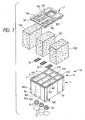
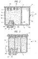
- Container body 1 is divided by a plurality of partitions 2, 3 and 4 to form three ink chambers 271, 272 and 273 for storing ink, with each chamber having a corresponding foam chamber 160, 161 and 162.
- Each foam chamber 160, 161, 162 is designed and constructed to accommodate a respective porous body 150, 151, 152, preferably made of a resilient material suitable for absorbing ink.
- Three ink supply ports 180, 181 and 182 are formed in bottom wall 1a below foam chambers 160, 161 and 162, respectively. Ink supply ports 180, 181 and 182 may be formed in front wall 1b, back wall 1c or side walls 1d.
- Each ink chamber 271, 272, 273 is designed to contain a quantity of liquid ink 67.
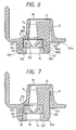
- ink supply ports 180, 181, 182 are shaped to receive an ink supply needle of a recording head (not shown), and are formed in bottom walls 160a, 161a, 162a of respective foam chambers 160, 161, 162.
- Ink supply ports 180, 181, 182 each include an upper step portion 180a, 181a, 182a, a lower step portion 180b, 181b, 182b, and a lower surface 180c, 181c, 182c.
- a packing member 115 is disposed within each supply port 180, 181, 182 to prevent leakage.
- outer surface 123 and rib 124 abut lower step portion 182b of ink supply port 180, 181, 182.
- Upper surfaces 119 and 125, and outer surface 121 of upper tubular portion 116 abut upper step portion 182a of ink supply port 180, 181, 182, and are preferably fixed to upper step portion 182a by means of an ink resistant adhesive 92. In this manner, a space S located between upper step portion 182a and upper surfaces 119 and 125 is completely filled, and ink 67 is prevented from leaking around packing member 115.
- seal 16 is preferably formed of a low-density polyethylene film that is very permeable to gas and impermeable to moisture, is secured over ink supply ports 180, 181, 182, and is capable of being breached by the ink supply needle prior to printing.
- a channel 127 located adjacent to ink supply ports 180, 181, 182, extending upward from bottom wall 162a into a dead space of protuberance 12 is provided as a space into which air that remains in ink supply ports 180, 181, 182 may be evacuated during the packaging process, described below.
- Channel 127 is sized such that channel 127 does not weaken the integrity of ink supply ports 180, 181, 182.
- Channel 127 is preferably located at the location of the dead space and proximal ink supply ports 180, 181, 182, exhaustion ports 190, 191, 192, or ink injection ports 100, 101, 102. However, channel 127 may also be located at any outer surface position of container body 1.
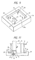
- FIG. 9 shows one embodiment of a pallet 20 formed in accordance with one embodiment of the invention, having a surface 20a, sized, spaced and arranged for transporting container body 1 during the course of the manufacture process.
- At least four inner pins 21 extend upwardly from pallet surface 20a sized, spaced and positioned for receiving the outer periphery of the surface of bottom wall 1a of container body 1.
- At least four outer pins 22 extend upwardly from pallet surface 20a sized, spaced and positioned for receiving an inner surface 1f of container body 1.
- container body 1 is positioned and set on pallet 20 by seating container body 1 in an upside-down position where bottom wall 1a of container body 1 faces upward and opening 1e faces pallet surface 20a, and inner surface 1f of container body 1 is positioned adjacent to pins 22, which hold body 1 to pallet 20.
- inner surfaces 1f, including filter 18, recess 13, protuberance 12, communication path 14, and ink supply port 180, 181, 182, of container body 1 may be exposed to ultraviolet radiation (or other suitable treatment) to improve the wettability of the surface.
- packing member 115 having a thinly applied adhesive 92 on upper surfaces 119, 125 is temporarily pressed into ink supply port 180, 181, 182 by a pressing jig 36 in a direction indicated by an arrow A, and is further pressed in the direction of arrow A to a predetermined position while, at the same time, to reduce friction, pressing jig 30 rotates about the center axis of jig 30 in a direction shown by an arrow B.
- By pressing packing member 115 while also torquing packing member 115 packing member 115 is fitted into ink supply port 180, 181, 182 without curling or distorting the peripheral edge of ink supply port 180, 181, 182.
- packing member 115 is reliably prevented from disengaging from ink supply ports 180, 181, 182 after foam chambers 271, 272, 278 have been filled with ink. Further, space S between packing member 115 and ink supply port 182 (FIG. 6), as well as the other corresponding spaces, are reliably filled and sealed with adhesive 92, thereby preventing air from entering container body 1 or ink from escaping container body 1 via space S.
- container body 1 is re-positioned on pallet 20 such that opening 1e of container body 1 faces upward and bottom wall 1a is flush with pallet surface 20a.
- the repositioning can be done manually, robotically or otherwise.
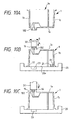
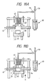
- FIG. 8 shows a porous member insertion device 39 constructed in accordance with an embodiment of the invention.
- porous member insertion device 39 comprises compression members 33 and 34, which are comb-shaped, and a press member 35 which is interposed between compression members 33 and 34.
- Compression members 33 and 34 include bases 33b, 34b and teeth 33a, 34a, which extend downwardly from bases 33b and 34b, respectively.
- the width between teeth 33a and 34a in a horizontal direction is shown as a double arrow X in FIG. 13A.
- Teeth 33a and 34a taper to free end 33c and 34c, respectively.
- Compression members 33 and 34 are moveable in the X direction by an activation means (not shown) to decrease the width to X', as shown in FIG. 13B.
- porous member 152 is sandwiched between compression members 33, 34 by actuation of compression members 33 and 34 toward press member 35 opposite the X direction until the distance between the outer edges of compression members 33 and 34 is smaller than the inner width of foam chamber 162. As such, porous member 152 is compressed to a size X' that fits within foam chamber 162.
- porous member insertion device 39 is positioned over foam chamber 162, such that tapered ends 33c and 34c of teeth 33a and 34a fit within foam chamber 162, and press member 35 is actuated by an activating means (not shown) to urge foam chamber 162 in the direction shown as an arrow Y in FIG. 13C.
- porous member 152 is pressed into foam chamber 162.
- press member 34 is lowered slightly further, and container body 1 is transported away from porous member insertion device 39.
- porous member 152 which is formed so as to be slightly larger than the volume of foam chamber 162, is positioned in foam chamber 162 in a compressed state.
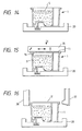
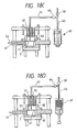
- cover 11 is positioned over opening 1e of container body 1 and is pressed toward container body 1 by a pressing means at a specified pressure in a direction indicated by arrow E. Further, by way of a jig 35, ultrasound vibrations are applied to cover 11 in the same plane as cover 11, in a direction perpendicular to cover 11, in a direction oblique to cover 11, or in a combination thereof. Thus, opening 1e of container body 1 is frictionally fused (ultrasonically welded) to the reverse side of cover 11.
- a heat rod 36 which is heated to a temperature sufficient to soften the material of container body 1 and cover 11, is brought into contact with the periphery of a heating plate or jig 38 shown in FIG. 19, thereby ensuring that heating plate 38 fuse-bonds (heat seals) seal 19 to cover 11.
- Hot air is then blown from an injection nozzle 37 onto container body 1, so as to help eliminate any burrs resulting from the attachment of cover 11 to container body 1.
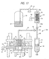
- FIG. 17 shows an ink filling apparatus 200, constructed in accordance with one embodiment of the invention.
- Filling apparatus 200 includes a table 40 for supporting pallet 20.
- Table 40 can be vertically actuated in the direction indicated by a double arrow F by means of a drive mechanism (not shown).
- container body 1 remains seated in pallet 20 in its upright position.
- a bed 41 having a through hole 41a, formed to accommodate container body 1, is positioned on a raised section 24.
- An injection chamber 43 is formed in through hole 41a by the combination of pallet 20, which forms a lower surface of chamber 43, and a cover member 42 which forms an upper surface of chamber 43.
- Injection chamber 43 is connected to a vacuum pump 45 via a channel 44 formed in bed 41.
- a through hole 46 is formed in cover member 42 so as to oppose injection chamber 43.
- a piston 47 is inserted into through hole 46, and is constructed to maintain injection chamber 43 in an air-tight state while moving vertically in a direction indicated by a double arrow G.
- Piston 47 includes an injection needle 48, positioned to face ink injection ports 100, 101, 102 of container body 1, set in injection chamber 43, and a channel 50, which faces atmospheric communication ports 190, 191, 192 of container body 1, and is connected to an air supply device (not shown).
- Injection needle 48 is connected to a branch tube 52 via a channel 49 formed in piston 47, a tube 51, and a stop valve 64.
- Ink filling apparatus 200 also includes a gas-liquid separation unit 53.
- gas-liquid separation unit 53 includes a hollow yarn bundle 54, which is preferably connected fluid-tight at both longitudinal ends to a cylinder 55 so as to permit fluid to flow therethrough.
- Cylinder 55 is connected to a vacuum pump 56 so as to produce negative pressure around the outer periphery of yarn bundle 54.
- Cylinder 55 includes an inlet 55a, which is connected to an ink tank 58, having ink 67 therein, via a tube 57, and an outlet 55b, which is connected to branch pipe 52 via a stop valve 58.
- Branch pipe 52 is also connected to a measuring tube 60 via a tube 63.
- Measuring tube 60 includes a cylinder 61 and a piston 62, and is preferably connected to branch pipe 52 at the center of one end of cylinder 61.
- stop valve 58 is closed to isolate gas-liquid separation unit 53, stop valve 64 is opened, and piston 62 of measuring tube 60 is pressed to discharge the predetermined quantity of ink 67 into foam chamber 160 via ink injection port 100.
- ink 67 which has been completely degassed by gas-liquid separation unit 53, is absorbed into porous member 150.
- gas trapped in the pores of porous member 150 that were not discharged in the foregoing depressurization step readily dissolves into ink 67. Therefore, ink 67 is uniformly absorbed by porous member 150 without causing air bubbles to form in porous member 150.
- foam chamber 160 When foam chamber 160 is filled with ink 67, air bubbles do not exist in at least porous members 150, and because air bubbles are not introduced via channel 50, ink 67 provided to the recording head via the porous member 150 is free of bubbles, thereby ensuring print quality.
- tube 51 is advantageously heated to a temperature of at least approximately 10 to 20 C° above the ambient temperature, so that ink 67 becomes less viscous and may more easily enter the pores of porous member 150. In this manner, any gas that had previously been contained in porous member 150 is more readily displaced by ink 67, thereby further ensuring reliable ink ejection and high quality.
- the remaining foam chambers 161, 162 are filled with ink by a similar process.
- channel 50 is opened to ambient air, so that ink 67 that remains on an upper part of porous member 150 is completely absorbed into porous member 150 by means of the pressure differential between the pressure in porous member 150 and ambient pressure.
- table 40 is lowered, and pallet 20 is transported to the next assembly station.
- the other porous members can be filled with ink in a similar fashion. Any ink that has adhered to ink injection port 100 during the filling process can be wiped off by vacuum suction or with a cloth.
- a conduit (not shown) is advantageously brought into contact with ink injection port 100, and a very small positive suction is applied to the conduit, thereby suctioning any ink adhered to the reverse-side of cover 11.
- container body 1 is housed in a depressurization container 38 and is inclined in such a way that exhausting ports 190, 191, 192 face upward.
- Seal 19 is formed so as to cover at least exhaustion ports 190, 191, 192, the ink inlet ports 100, 101, 102 and grooves 170, 171, 172 and can be temporarily adhered to cover 11 by heat welding or otherwise.
- seal 19 covering grooves 170, 171, 172 is heated, so that a part of seal 19 is welded to the surface of cover 11 such that is sealed.
- capillaries are formed by grooves 170, 171, 172 and seal 19. The principal portion of the remainder of seal 19 is adhered to cover 11 such that it can be readily peeled away from cover 11.
- ink cartridge 1 in another embodiment of a method of manufacturing ink tank cartridge 1, after heat fusing seal 19 to cover grooves 170, 171, 172, the additional step of housing the ink cartridge in an evacuation chamber and evacuating ink cartridge 1 prior to the other portion of seal 19 being heat fused to cover 11 is performed. In this manner, ink cartridge 1 may be decompressed again to prevent the formation of foam in the vicinity of packing member 115.
- ink cartridge 1 is evacuated to approximately 200 mm Hg (-200 mm) below atmospheric pressure so that ink 67 may be prevented from being ejected from ink inlet ports 100, 101, 102, thereby maximizing the amount of ink 67 contained in ink cartridge 1.
- an ink cartridge can be efficiently manufactured by transporting the ink cartridge on the pallet at several or each step of the manufacturing process.
- in an ink-filled ink cartridge 70 at least ink supply ports 180, 181, 182 are bought into contact with a buffer 71 so as to prevent seals 16 from rupturing. As is described above, it is understood that each ink supply port 180, 181, 182 is sealed with a seal 16. Further, tongue 19a of seal 19 is folded, and ink cartridge 70 is then inserted into a bag 72, which is preferably formed from a gas-insulating film, and has a collar 72a. Collar 72a is arranged near the opening of bag 72, and is folded inwardly to a uniform thickness. The opening of bag 72 is heat welded in a vacuum environment as shown in FIG. 21A.
- channel 127 provided in the vicinity of ink supply port 182 and any other space within bag 72 forms decompressed space.
- seals 16 are composed of a low-density polyethylene film which is very permeable to gas, the air dissolved in ink 67 in the vicinity of ink supply port 180, 181, 182 passes through seals 16 and is contained in the decompressed space provided in channel 127 and bag 72.
- this step is performed within approximately 72 hours after the second depressurization step.
- the quantity of dissolved air in ink cartridge 70 is minimized and foams are prevented from forming by composing seal 16 for sealing ink supply port 180, 181, 182 and seal 19 for sealing ink injection ports 100, 101, 102, exhaustion ports 190, 191, 192, and grooves 170, 171, 172 of cover 11 by a film, such as a low-density polyethylene film, that is very permeable to gas and is not permeable to moisture.
- a film such as a low-density polyethylene film
- ink in ink cartridge 70 is held in a vacuum of approximately -200 or even -300 mm Hg to securely dissolve foams in ink 67 and remove the foams by permitting the air to pass through seal 16 or seal 19.
- ink 67 is held in a high degree of degassing as described above, it is desirable that the volume of channel 127 be increased.
- a concave portion and a through hole are provided to thick cushioning material 71 to positively form dead space between bag 72 and ink cartridge 70 and a spacer is provided for sealing.
- the present invention has been described with reference to the cartridge having multiple ink chambers, the present invention can be applied to the manufacture of an ink cartridge 75 such as that shown in FIG. 22, where ink is only filled into porous member 5 housed in container body 1'.
- only one opening 77 may be formed in a cartridge 76 so as to serve as an ink inlet port and an atmospheric communication port.
- ink injection needle 48 and channel 50 connected to the exhaust device are provided coaxially with respect to each other.
- one opening 77 can be used both for ink injection and air exhaust operations.
- the present invention further provides an ink tank cartridge (70) for use in an ink jet recording apparatus, comprising: a tank body (1) having a plurality of exterior walls (1a, 1b, 1c, 1d) defining an interior space; at least one porous member (150, 151, 152) within said interior space of the tank body; at least one port (180, 181, 182) extending through one of said exterior walls of said body (1); a gas-permeable seal (16) for sealing said port (180, 181, 182); and a gas-impermeable seal (72) for sealing the ink tank cartridge (70) and defining a decompressed dead space into which gas dissolved in said tank body (1) can flow via said ink supply port (180, 181, 182) and said gas-permeable seal (16) when said ink tank cartridge (70) is sealed.
- At least one of said plurality of exterior walls (1a, 1b, 1c, 1d) may have an outer surface defining a channel, at least in part defining said decompressed dead space.
- Said ports (180, 181, 182) may be configured and coupled to the interior of the tank body (1) to serve as an ink port for supplying ink to the exterior of the cartridge (70) or injecting ink into the interior of the cartridge (70).
- Said ports (180, 181, 182) may alternativeatively be configured and coupled to the interior of the ink tank body (1) to serve as an exhaustion port for exhausting gas from the interior of the cartridge (70).
- the gas-permeable seal (16) preferably comprises a low-density polyethylene film.
- the ink tank cartridge of claim 9, further comprise a cushioning material to positively form dead space outside the ink cartridge (70).
- an ink tank cartridge (70) for use in an ink jet recording apparatus, comprising: a body (1) having exterior walls (1a, 1b, 1c, 1d) and defining an interior portion; an ink supply port (180, 181, 182), extending through one of said exterior walls (1a, 1b, 1c, 1d) of said body (1) to supply ink to the exterior of the cartridge (70), said ink supply port (180, 181, 182) including a bore defined by an inner surface, and wherein at least a portion of said inner surface has a hydrophilic property.
- the present invention furthermore provides a method of manufacturing an ink cartridge (70) having an ink supply port (180, 181, 182), having an inlet, formed in the container body (1), for use in an ink jet recorder, comprising the step of treating at least a portion of the ink supply port inlet with ultraviolet radiation to improve the wettability of the treated portion.
- the present invention futhermore provides a method of manufacturing an ink cartridge (70) for use in an ink jet recorder, comprising the step of heating ink while it is being injected into the ink cartridge (70), to a temperature of at least approximately 10°C above the ambient temperature of the ink.
- the present invention furthermore provides a method of manufacturing an ink cartridge (70) for use in an ink jet recorder, comprising the step of heating ink while it is being injected into the ink cartridge (70), to a temperature of between approximately 10°C and 20°C above the ambient temperature of the ink.
- the present invention furthermore provides a method of manufacturing an ink cartridge (70) for use in an ink jet recorder, comprising the step of heating ink while it is being injected into the ink cartridge (70), to a temperature of more than 20°C above the ambient temperature of the ink.
- the present invention furthemore privdes a method of manufacturing an ink cartridge for use in an ink jet recorder, comprising the step of providing a container body (1) having a first wall and a plurality of walls extending upwardly therefrom to define an opening spaced from the bottom walls on a pallet, the container body (1) including a chamber for accommodating a porous member (150, 151, 152) therein, and an ink supply port (180, 181, 182), having an inlet formed in the bottom surface of the chamber and an outlet; inserting a packing member (115) into the ink supply port (180, 181, 182) and then sealing the ink supply port outlet; inserting a porous member (150, 151, 152) into the foam chamber (160, 161, 162); bonding a cover (11) to the opening of the container body (1); depressurizing the ink cartridge (70) a first time; injecting ink into the foam chamber (160, 161, 162) after the first depressurizing step; depressurizing the ink cartridge (70)
- the container Prior to inserting the packing member (115), the container may be positioned on a pallet such that the first wall faces upward away from the top of the pallet, and after inserting the packing member (115), resetting the container body on the pallet by turning the container body (1) upside down such that the opening faces upward and the first wall faces the pallet.
- the method may, furthermore, comprise the step of affixing a filter to the ink supply port inlet.
- the ink cartridge (70) may be depressurized to approximately 200 mm Hg below atmospheric pressure during the second depressurization step.
- the method may, furthermore, comprise the steps of inserting the container body (1) into a bag having an opening and sealing the bag opening in a vacuum environment.
- the present invention further provides a method of manufacturing an ink cartridge for use in an ink jet recorder, comprising the step of providing a container body (1) having a first wall and a plurality of walls (1a, 1b, 1c, 1d) extending upwardly therefrom to define an opening spaced from the bottom walls on a pallet, the container body (1) including a foam chamber (160, 161, 162) for accommodating a porous member (150, 151, 152) therein, and an ink supply port (180, 181, 182), having an inlet formed in the bottom surface of the foam chamber (160, 161, 162) and an outlet; inserting packing member (115) into the ink supply port (180, 181, 182) and then sealing the ink supply port outlet; inserting a porous member (150, 151, 152) into the foam chamber (160, 161, 162); bonding a cover (11) to the opening of the container body (1); depressurizing the ink cartridge (70) a first time; injecting ink into the foam chamber (160, 161,
- the bag opening may be sealed in a vacuum environment within approximately 72 hours after the second depressurization step.
- the container Prior to inserting the packing member (115), the container may be positioned on a pallet such that the first wall faces upward away from the top of the pallet, and after inserting the packing member (115), resetting the container body (1) on the pallet by turning the container body (1) upside down such that the opening faces upward and the first wall faces the pallet.
- the method may furthemore, comprise the step of affixing a filter to the ink supply port inlet.
Abstract
Description
Accordingly, it is an object of the present invention to develop an ink tank cartridge for use with an ink jet recorder and a method for manufacturing an ink cartridge for use in an ink jet recorder, that overcomes disadvantages and limitations of existing products and methods. To solve this object the present invention provides an ink tank cartridge as specified in
The claims are understood as a first non-limiting approach for defining the invention in general terms.
An ink tank cartridge for use in an ink jet recorder which is convenient to manufacture, assemble, store and connect, which helps prevent the formation of bubbles in the ink is provided. The cartridge can include a container body having exterior walls, a porous member stored in the container, an ink supply port that extends through one of the exterior walls of the body to supply ink to the exterior of the cartridge, and a packing member, disposed within the ink supply port and having an opening therethrough and a rib formed on a upper surface is provided. A pressing member may be provided to bias the packing member against an inner surface of the ink supply port. The ink cartridge for the inkjet recording apparatus can be constructed to exhaust air retained within the ink supply port. The ink tank cartridge can also be constructed to efficiently prevent air from entering into the ink cartridge through the ink supply port.
Claims (8)
- An ink tank cartridge (70) for use in an ink jet recording apparatus, comprising:wherein a rib (120) is formed on said upper surface (119), and wherein another rib (124) is formed on an outer surface of said packing member.a tank body (1) having exterior walls (1a, 1b, 1c, 1d);a porous member (150, 151, 152) stored in said tank body (1);an ink supply port (180, 181, 182) configured to receive an ink supply needle of an ink jet recording head, the supply port having an inner surface, defined by and extending through one of said exterior walls of said body (1) to supply ink to the exterior of the cartridge (70); anda packing member (115) disposed within said ink supply port (180, 181, 182), said packing member (115) having an opening therethrough, a lower surface (122) and an upper surface (119),
- The ink tank cartridge of claim 1, comprising an adhesive layer attaching said packing member to said ink port surface.
- The ink tank cartridge of claim 2, wherein said adhesive layer is ink-resistant.
- The ink tank cartridge of any one of claims 1 to 3, comprising a pressing member (90) having a window (91), the pressing member (90) pressing against said lower surface (122) of said packing member (115) and biasing said packing member (115) against said inner surface of said ink supply port (180, 181, 182).
- The ink tank cartridge of claim 4, wherein said rib (120) is maintained in an elastically deformed condition as a result of the pressing from the pressing member (90) said rib (120).
- The ink tank cartridge of claim 4 or 5, wherein said window (91) is a thin film.
- The ink tank cartridge of claim 4, wherein said pressing member (90) is thermally welded to said body (1).
- The ink tank cartridge of claim 1, wherein the inner surface of the ink supply port (180, 181, 182) has been treated to increase the hydrophilic properties thereof.
Applications Claiming Priority (4)
| Application Number | Priority Date | Filing Date | Title |
|---|---|---|---|
| JP7658297 | 1997-03-12 | ||
| JP9076582A JPH10250104A (en) | 1997-03-12 | 1997-03-12 | Ink cartridge for ink-jet type recording apparatus, and its manufacture |
| EP98104500A EP0864428B1 (en) | 1997-03-12 | 1998-03-12 | Ink cartridge for ink jet recorder and method of manufacturing same |
| EP00106529A EP1046508B1 (en) | 1997-03-12 | 1998-03-12 | Cartridge for ink-jet recorder |
Related Parent Applications (3)
| Application Number | Title | Priority Date | Filing Date |
|---|---|---|---|
| EP98104500.8 Division | 1998-03-12 | ||
| EP00106529A Division EP1046508B1 (en) | 1997-03-12 | 1998-03-12 | Cartridge for ink-jet recorder |
| EP00106529.1 Division | 2000-03-27 |
Publications (3)
| Publication Number | Publication Date |
|---|---|
| EP1598197A2 true EP1598197A2 (en) | 2005-11-23 |
| EP1598197A3 EP1598197A3 (en) | 2007-04-18 |
| EP1598197B1 EP1598197B1 (en) | 2008-11-26 |
Family
ID=13609288
Family Applications (5)
| Application Number | Title | Priority Date | Filing Date |
|---|---|---|---|
| EP98104500A Expired - Lifetime EP0864428B1 (en) | 1997-03-12 | 1998-03-12 | Ink cartridge for ink jet recorder and method of manufacturing same |
| EP05018497A Expired - Lifetime EP1598197B1 (en) | 1997-03-12 | 1998-03-12 | Ink cartridge for ink-jet recorder |
| EP00106529A Expired - Lifetime EP1046508B1 (en) | 1997-03-12 | 1998-03-12 | Cartridge for ink-jet recorder |
| EP00106530A Expired - Lifetime EP1013442B1 (en) | 1997-03-12 | 1998-03-12 | Method of manufacturing ink cartridge for ink-jet recorder |
| EP00106528A Expired - Lifetime EP1013441B1 (en) | 1997-03-12 | 1998-03-12 | Ink cartridge for ink-jet recorder and method of manufacturing same |
Family Applications Before (1)
| Application Number | Title | Priority Date | Filing Date |
|---|---|---|---|
| EP98104500A Expired - Lifetime EP0864428B1 (en) | 1997-03-12 | 1998-03-12 | Ink cartridge for ink jet recorder and method of manufacturing same |
Family Applications After (3)
| Application Number | Title | Priority Date | Filing Date |
|---|---|---|---|
| EP00106529A Expired - Lifetime EP1046508B1 (en) | 1997-03-12 | 1998-03-12 | Cartridge for ink-jet recorder |
| EP00106530A Expired - Lifetime EP1013442B1 (en) | 1997-03-12 | 1998-03-12 | Method of manufacturing ink cartridge for ink-jet recorder |
| EP00106528A Expired - Lifetime EP1013441B1 (en) | 1997-03-12 | 1998-03-12 | Ink cartridge for ink-jet recorder and method of manufacturing same |
Country Status (5)
| Country | Link |
|---|---|
| US (4) | US6312115B1 (en) |
| EP (5) | EP0864428B1 (en) |
| JP (1) | JPH10250104A (en) |
| DE (5) | DE69832201T2 (en) |
| HK (3) | HK1029965A1 (en) |
Families Citing this family (66)
| Publication number | Priority date | Publication date | Assignee | Title |
|---|---|---|---|---|
| JPH10250104A (en) | 1997-03-12 | 1998-09-22 | Seiko Epson Corp | Ink cartridge for ink-jet type recording apparatus, and its manufacture |
| EP0949080A3 (en) * | 1998-04-06 | 2000-01-26 | Xerox Corporation | Ink container with improved sealing of ink container outlet port |
| SG95595A1 (en) * | 1998-05-13 | 2003-04-23 | Seiko Epson Corp | Ink cartridge for ink-jet printing apparatus |
| DE69938202T3 (en) * | 1998-07-15 | 2013-06-13 | Seiko Epson Corp. | An ink supply system |
| KR100362908B1 (en) | 1998-11-11 | 2002-11-29 | 세이코 엡슨 가부시키가이샤 | Inkjet type recording apparatus, ink supplying system and ink cartridge |
| US6799820B1 (en) * | 1999-05-20 | 2004-10-05 | Seiko Epson Corporation | Liquid container having a liquid detecting device |
| DE19943948B4 (en) | 1999-09-14 | 2005-07-14 | Artech Gmbh Design + Production In Plastic | Method for producing an ink cartridge for an inkjet printer |
| JP2001105599A (en) | 1999-10-05 | 2001-04-17 | Canon Inc | Liquid jet head, producing method therefor and liquid jet apparatus |
| ATE340027T1 (en) * | 1999-10-22 | 2006-10-15 | Ngk Insulators Ltd | FLUID DISPENSER FOR PRODUCING DNA MICROARRAYS |
| JP4282043B2 (en) * | 1999-12-06 | 2009-06-17 | キヤノン株式会社 | Recording liquid supply passage, recording liquid storage container, recording liquid supply apparatus including these, and surface modification method thereof |
| US7137679B2 (en) * | 2000-05-18 | 2006-11-21 | Seiko Epson Corporation | Ink consumption detecting method, and ink jet recording apparatus |
| CN1198730C (en) | 2000-05-18 | 2005-04-27 | 精工爱普生株式会社 | Method and apparatus for detecting consumption of ink |
| KR100439616B1 (en) * | 2000-05-18 | 2004-07-12 | 세이코 엡슨 가부시키가이샤 | Mounting structure, module body and liquid container |
| EP1283110B1 (en) * | 2000-05-18 | 2009-03-04 | Seiko Epson Corporation | Ink consumption detecting method, and ink jet recording apparatus |
| DK1679196T3 (en) * | 2000-06-15 | 2008-08-25 | Seiko Epson Corp | Liquid filling process, liquid container and process for making it |
| KR100640677B1 (en) | 2000-07-07 | 2006-11-02 | 세이코 엡슨 가부시키가이샤 | Liquid container, ink-jet recording apparatus, device and method for controlling the apparatus, liquid consumption sensing device and method |
| EP1176403A3 (en) * | 2000-07-28 | 2003-03-19 | Seiko Epson Corporation | Detector of liquid consumption condition |
| JP2002207807A (en) * | 2000-09-19 | 2002-07-26 | Seiko Epson Corp | Separately sold parts of equipment, equipment having separately sold parts, access device, method for distributing separately sold parts, and ink cartridge |
| US6776477B2 (en) * | 2000-10-06 | 2004-08-17 | Seiko Epson Corporation | Mechanical seal cap for ink-cartridge |
| JP3770315B2 (en) | 2000-12-25 | 2006-04-26 | セイコーエプソン株式会社 | ink cartridge |
| JP4193435B2 (en) | 2002-07-23 | 2008-12-10 | ブラザー工業株式会社 | Ink cartridge and ink filling method thereof |
| EP1258362B1 (en) * | 2001-05-17 | 2010-08-11 | Seiko Epson Corporation | Ink cartridge and method of ink injection thereinto |
| EP1258361B1 (en) * | 2001-05-17 | 2009-03-11 | Seiko Epson Corporation | Method of ink injection into an ink cartridge |
| DE10125957A1 (en) * | 2001-05-29 | 2002-12-12 | Artech Gmbh Design & Prod | Method for filling an inkjet printer ink cartridge includes a final stage in which the cartridge is subjected to centrifugal action to force ink thought an outlet filter so that it extends right up to the outlet seal |
| CN2571588Y (en) | 2001-09-19 | 2003-09-10 | 精工爱普生株式会社 | Ink cartridge |
| US20040189755A1 (en) * | 2001-11-03 | 2004-09-30 | Studholme John William | Authentication of a remote user to a host in data communication system |
| US6692116B2 (en) * | 2002-06-06 | 2004-02-17 | Eastman Kodak Company | Replaceable ink jet print head cartridge assembly with reduced internal pressure for shipping |
| EP1375162B1 (en) * | 2002-06-28 | 2008-09-17 | Océ-Technologies B.V. | Ink tank for ink jet |
| TWI296239B (en) * | 2002-06-28 | 2008-05-01 | Oce Tech Bv | Ink tank for ink jet |
| KR20040020146A (en) * | 2002-08-29 | 2004-03-09 | 삼성전자주식회사 | Ink-cartridge |
| KR20040020147A (en) * | 2002-08-29 | 2004-03-09 | 삼성전자주식회사 | Ink-cartridge |
| JP2004174961A (en) | 2002-11-28 | 2004-06-24 | Brother Ind Ltd | Ink jet recorder and its ink introducing method |
| KR100487585B1 (en) * | 2002-12-20 | 2005-05-03 | 주식회사 프린톤 | Method of refilling ink in an ink cartridge for an inkjet printer |
| JP2004338383A (en) * | 2003-04-25 | 2004-12-02 | Canon Inc | Ink cartridge, printing device equipped with ink cartridge, and manufacturing process of ink tank |
| US6948805B2 (en) * | 2003-04-29 | 2005-09-27 | Hewlett-Packard Development Company, L.P. | Ink cartridge reservoir |
| US7207667B2 (en) * | 2003-06-24 | 2007-04-24 | Tonerhead, Inc. | Apparatus and method for refurbishing used cartridges for ink jet type imaging devices |
| US7290869B2 (en) * | 2003-07-25 | 2007-11-06 | Seiko Epson Corporation | Liquid container |
| US7384133B2 (en) * | 2003-08-08 | 2008-06-10 | Seiko Epson Corporation | Liquid container capable of maintaining airtightness |
| US7261397B2 (en) * | 2003-08-19 | 2007-08-28 | Canon Kabushiki Kaisha | Tank unit, ink jet recording head and method of manufacturing tank unit and ink jet recording head |
| ES2268261T7 (en) * | 2003-11-19 | 2009-06-18 | 3T Supplies Ag | INK CARTRIDGE, INK CARTRIDGE GROUP AND PRINT HEAD BY INK JET. |
| US7334887B2 (en) * | 2004-01-12 | 2008-02-26 | Nu-Kote International, Inc. | Ink container for an ink jet cartridge |
| US7118206B1 (en) * | 2004-03-19 | 2006-10-10 | 3D Systems, Inc. | Gas bubble removal from ink-jet dispensing devices |
| US20060253844A1 (en) | 2005-04-21 | 2006-11-09 | Holt John M | Computer architecture and method of operation for multi-computer distributed processing with initialization of objects |
| US7844665B2 (en) | 2004-04-23 | 2010-11-30 | Waratek Pty Ltd. | Modified computer architecture having coordinated deletion of corresponding replicated memory locations among plural computers |
| JP2006168794A (en) * | 2004-12-16 | 2006-06-29 | Seiko Epson Corp | Pack body, droplet discharge device, electro-optic device and electronic device |
| US7429101B2 (en) * | 2005-04-22 | 2008-09-30 | Hewlett-Packard Development Company, L.P. | Ink supply with ink/air separator assembly that is isolated from ink until time of use |
| JP4725182B2 (en) * | 2005-04-28 | 2011-07-13 | セイコーエプソン株式会社 | Method for manufacturing liquid supply system and liquid supply system |
| US7325909B2 (en) * | 2005-04-28 | 2008-02-05 | Kenneth Yuen | Automatic ink refill system and methods |
| DE602006012896D1 (en) * | 2005-04-28 | 2010-04-29 | Brother Ind Ltd | Ink jet recording apparatus and control thereof |
| US7556364B2 (en) | 2005-12-05 | 2009-07-07 | Silverbrook Research Pty Ltd | Ink cartridge with self sealing outlet valve |
| SG133454A1 (en) * | 2005-12-27 | 2007-07-30 | Inke Pte Ltd | Colour cartridge refilling apparatus |
| US7607768B2 (en) * | 2006-03-21 | 2009-10-27 | Hewlett-Packard Development Company, L.P. | Liquid supply means |
| US8322835B2 (en) * | 2007-02-19 | 2012-12-04 | Seiko Epson Corporation | Sealing structure of fluid container, and method of manufacturing and reusing fluid container |
| JP2008230214A (en) * | 2007-02-19 | 2008-10-02 | Seiko Epson Corp | Sealing structure and sealing method of fluid lead-out part, fluid container, refilling fluid container, and its refilling method |
| JP5162651B2 (en) * | 2010-12-20 | 2013-03-13 | 富士ゼロックス株式会社 | Liquid supply device |
| JP5213973B2 (en) | 2011-02-18 | 2013-06-19 | 富士フイルム株式会社 | Image recording liquid cartridge and image forming apparatus |
| JP5754989B2 (en) * | 2011-03-09 | 2015-07-29 | キヤノン株式会社 | Method for manufacturing liquid storage device |
| US9539812B2 (en) | 2012-12-14 | 2017-01-10 | Hewlett Packard Devleopment Company, L.P. | Fluid flow structure |
| JP6230231B2 (en) * | 2012-12-28 | 2017-11-15 | キヤノン株式会社 | Ink tank |
| GB2526033B (en) * | 2013-03-20 | 2020-01-01 | Hewlett Packard Development Co | Printhead assembly with fluid interconnect cover |
| JP2016172325A (en) * | 2015-03-16 | 2016-09-29 | 株式会社リコー | Liquid heating device and image forming device |
| JP6611564B2 (en) * | 2015-10-30 | 2019-11-27 | キヤノン株式会社 | Liquid storage bottle and liquid storage bottle package |
| JP6930074B2 (en) * | 2016-08-12 | 2021-09-01 | セイコーエプソン株式会社 | Liquid containment |
| CN111267494B (en) * | 2020-02-27 | 2021-04-02 | 宁波润爵科技有限公司 | Assembling equipment for printer ink box |
| US11801370B2 (en) * | 2021-02-17 | 2023-10-31 | Funai Electric Co., Ltd. | Gas management for jetting cartridge |
| JP2022168619A (en) * | 2021-04-26 | 2022-11-08 | 船井電機株式会社 | Ink cartridge, cartridge holding mechanism, and printer |
Citations (1)
| Publication number | Priority date | Publication date | Assignee | Title |
|---|---|---|---|---|
| EP0581531A1 (en) | 1992-07-24 | 1994-02-02 | Canon Kabushiki Kaisha | Ink container, ink and ink jet recording apparatus using ink container |
Family Cites Families (63)
| Publication number | Priority date | Publication date | Assignee | Title |
|---|---|---|---|---|
| JPS58101066A (en) * | 1981-12-09 | 1983-06-16 | Konishiroku Photo Ind Co Ltd | Ink jet recorder |
| US5182572A (en) * | 1981-12-17 | 1993-01-26 | Dataproducts Corporation | Demand ink jet utilizing a phase change ink and method of operating |
| US4454518A (en) * | 1982-05-12 | 1984-06-12 | Ncr Corporation | Temperature control of ink for ink jet printer |
| JPS59131837U (en) * | 1983-02-23 | 1984-09-04 | シャープ株式会社 | Ink cartridge device for inkjet printers |
| JP3513979B2 (en) | 1994-09-16 | 2004-03-31 | セイコーエプソン株式会社 | Ink cartridge for inkjet printer |
| US4771295B1 (en) * | 1986-07-01 | 1995-08-01 | Hewlett Packard Co | Thermal ink jet pen body construction having improved ink storage and feed capability |
| JPS63153146A (en) * | 1986-12-17 | 1988-06-25 | Ricoh Co Ltd | Ink cartridge for ink jet recording apparatus |
| US4814786A (en) * | 1987-04-28 | 1989-03-21 | Spectra, Inc. | Hot melt ink supply system |
| JPS63276554A (en) | 1987-05-08 | 1988-11-14 | Ricoh Co Ltd | Ink cartridge apparatus |
| US4843796A (en) * | 1988-03-22 | 1989-07-04 | Ecs Corporation | Method and apparatus for vacuum packaging |
| JP2757199B2 (en) | 1989-01-31 | 1998-05-25 | スズキ株式会社 | Knock control device for internal combustion engine |
| US5244092A (en) | 1989-12-06 | 1993-09-14 | Canon Kabushiki Kaisha | Package for ink jet cartridge |
| US5131539A (en) | 1989-12-06 | 1992-07-21 | Canon Kabushiki Kaisha | Package for ink jet cartridge |
| JP3171214B2 (en) | 1992-01-28 | 2001-05-28 | セイコーエプソン株式会社 | Ink cartridge for inkjet recording device |
| JP3160312B2 (en) | 1990-07-10 | 2001-04-25 | キヤノン株式会社 | Ink jet cartridge and recording apparatus using the cartridge |
| JP3169958B2 (en) | 1990-10-05 | 2001-05-28 | セイコーエプソン株式会社 | Ink tank |
| ATE157046T1 (en) | 1991-01-18 | 1997-09-15 | Canon Kk | METHOD FOR PRODUCING A COLOR RAY RECORDING HEAD |
| JPH05315660A (en) * | 1991-04-25 | 1993-11-26 | Ricoh Co Ltd | Manufacture of semiconductor integrated circuit device |
| JP2829447B2 (en) | 1991-06-24 | 1998-11-25 | 株式会社ブリヂストン | Method for compressing and filling urethane foam |
| JPH0516387A (en) | 1991-07-15 | 1993-01-26 | Canon Inc | Package for ink jet cartridge |
| ATE162469T1 (en) * | 1991-10-31 | 1998-02-15 | Canon Kk | INK JET HEAD AND ITS MANUFACTURING PROCESS |
| US5790158A (en) * | 1992-01-28 | 1998-08-04 | Seiko Epson Corporation | Ink-jet recording apparatus and ink tank cartridge therefor |
| EP0782927B1 (en) * | 1992-01-28 | 2001-11-07 | Seiko Epson Corporation | A fluid sealable container for an ink tank cartridge |
| JP3108788B2 (en) * | 1992-03-18 | 2000-11-13 | セイコーエプソン株式会社 | Inkjet head cleaning method and apparatus |
| JPH05345420A (en) | 1992-06-15 | 1993-12-27 | Canon Inc | Ink jet recording apparatus |
| JPH06966A (en) | 1992-06-18 | 1994-01-11 | Fuji Xerox Co Ltd | Ink jet cartridge, and ink tank and ink jet head which are used therefor |
| US5400060A (en) | 1992-06-25 | 1995-03-21 | Xerox Corporation | Thermal ink jet cartridge face sealing for shipping |
| JPH0615846A (en) | 1992-07-01 | 1994-01-25 | Canon Inc | Driving circuit for ink jet record head |
| JPH06106732A (en) | 1992-09-28 | 1994-04-19 | Fuji Xerox Co Ltd | Ink jet recording device |
| WO1994011195A1 (en) * | 1992-11-12 | 1994-05-26 | Graphic Utilities, Inc. | Method for refilling ink jet cartridges |
| JP3233175B2 (en) * | 1993-03-11 | 2001-11-26 | セイコーエプソン株式会社 | Ink jet recording device |
| JPH06311824A (en) | 1993-04-28 | 1994-11-08 | Mitsubishi Kasei Corp | Film for culturing fruit tree |
| DE69414296T2 (en) | 1993-05-03 | 1999-03-25 | Hewlett Packard Co | Frame made of two materials with different properties for thermal inkjet printhead |
| JP3199092B2 (en) * | 1993-11-05 | 2001-08-13 | セイコーエプソン株式会社 | Ink cartridge for printer |
| JPH06330099A (en) | 1993-05-25 | 1994-11-29 | Kao Corp | Article for bleaching treatment |
| EP0627317B1 (en) | 1993-05-25 | 1998-08-12 | Canon Kabushiki Kaisha | Packing case and opening method therefor |
| ES2176559T3 (en) * | 1993-06-29 | 2002-12-01 | Canon Kk | DEPOSIT FOR LIQUIDS, CARTRIDGE FOR INK JETS THAT HAS DICHODEPOSITE FOR LIQUIDS AND APPLIANCE FOR INK JETS THAT HAS DICHOCARTUCHO FOR INK JETS. |
| US5479968A (en) * | 1993-08-16 | 1996-01-02 | Xerox Corporation | Ink filling apparatus and method for filling ink cartridges |
| US5790157A (en) * | 1993-08-31 | 1998-08-04 | Canon Kabushiki Kaisha | Ink filling method and apparatus for ink cartridge |
| JP3168122B2 (en) * | 1993-09-03 | 2001-05-21 | キヤノン株式会社 | Ink jet head and ink jet recording apparatus provided with the ink jet head |
| JP3259481B2 (en) | 1993-11-09 | 2002-02-25 | セイコーエプソン株式会社 | Ink tank and manufacturing method thereof |
| JP3145573B2 (en) | 1994-07-29 | 2001-03-12 | キヤノン株式会社 | Ink jet recording device and ink tank |
| JP3065204B2 (en) | 1993-12-09 | 2000-07-17 | 株式会社大協精工 | Polysulfone resin composition and medical / pharmaceutical device comprising the same |
| JPH07164638A (en) | 1993-12-16 | 1995-06-27 | Fuji Electric Co Ltd | Ink jet printer and manufacture thereof |
| JP3253206B2 (en) | 1994-01-14 | 2002-02-04 | キヤノン株式会社 | Ink filling method |
| JP3101482B2 (en) | 1994-01-31 | 2000-10-23 | キヤノン株式会社 | Method and apparatus for manufacturing liquid holding container |
| JPH07227153A (en) | 1994-02-17 | 1995-08-29 | Mitsubishi Chem Corp | High-ridge fruit plant cultivation method |
| JP3424313B2 (en) | 1994-03-28 | 2003-07-07 | セイコーエプソン株式会社 | Ink tank manufacturing method |
| JPH07276629A (en) | 1994-04-12 | 1995-10-24 | Fuji Electric Co Ltd | Hydrophilicity treatment method and device for ink jet recording head |
| JP3603329B2 (en) | 1994-05-13 | 2004-12-22 | 大日本インキ化学工業株式会社 | Ink degassing method |
| DE69511461T2 (en) * | 1994-05-31 | 2000-04-13 | Canon Kk | Interchangeable ink cartridge with locking structure |
| JPH08132636A (en) | 1994-09-16 | 1996-05-28 | Seiko Epson Corp | Ink cartridge for ink jet printer and filling of cartridge with ink |
| JPH0966608A (en) | 1995-08-30 | 1997-03-11 | Brother Ind Ltd | Ink jet recorder |
| JP3347559B2 (en) | 1994-12-28 | 2002-11-20 | キヤノン株式会社 | Ink tank, inkjet cartridge, and inkjet recording apparatus |
| US6022103A (en) * | 1995-02-07 | 2000-02-08 | Canon Kabushiki Kaisha | Method for positioning an ink cartridge, and the ink cartridge and ink jet recording apparatus used for such method |
| JPH08230207A (en) | 1995-03-01 | 1996-09-10 | Canon Inc | Ink tank and production thereof |
| JPH0958009A (en) | 1995-08-23 | 1997-03-04 | Seiko Epson Corp | Ink cartridge, packing case therefor and packing method |
| US6102517A (en) * | 1995-12-25 | 2000-08-15 | Seiko Epson Corporation | Ink-jet recording apparatus for ink cartridge |
| US5879615A (en) * | 1996-07-22 | 1999-03-09 | Guardian Fiberglass, Inc. | Method of impregnating a mineral fiber insulation batt with extruded synthetic fibers |
| JP3245092B2 (en) | 1996-09-11 | 2002-01-07 | キヤノン株式会社 | Liquid injection method |
| JPH10138507A (en) | 1996-11-14 | 1998-05-26 | Seiko Epson Corp | Manufacture of ink cartridge for ink jet recording unit |
| JPH10250104A (en) * | 1997-03-12 | 1998-09-22 | Seiko Epson Corp | Ink cartridge for ink-jet type recording apparatus, and its manufacture |
| JP3892098B2 (en) * | 1997-03-19 | 2007-03-14 | ブラザー工業株式会社 | Ink injection method to ink cartridge |
-
1997
- 1997-03-12 JP JP9076582A patent/JPH10250104A/en active Pending
-
1998
- 1998-03-12 DE DE69832201T patent/DE69832201T2/en not_active Expired - Lifetime
- 1998-03-12 US US09/041,890 patent/US6312115B1/en not_active Expired - Lifetime
- 1998-03-12 EP EP98104500A patent/EP0864428B1/en not_active Expired - Lifetime
- 1998-03-12 DE DE69840280T patent/DE69840280D1/en not_active Expired - Lifetime
- 1998-03-12 EP EP05018497A patent/EP1598197B1/en not_active Expired - Lifetime
- 1998-03-12 DE DE69801246T patent/DE69801246T2/en not_active Expired - Lifetime
- 1998-03-12 EP EP00106529A patent/EP1046508B1/en not_active Expired - Lifetime
- 1998-03-12 EP EP00106530A patent/EP1013442B1/en not_active Expired - Lifetime
- 1998-03-12 EP EP00106528A patent/EP1013441B1/en not_active Expired - Lifetime
- 1998-03-12 DE DE69830501T patent/DE69830501T2/en not_active Expired - Lifetime
- 1998-03-12 DE DE69810642T patent/DE69810642T2/en not_active Expired - Lifetime
-
2000
- 2000-12-27 HK HK00108422A patent/HK1029965A1/en not_active IP Right Cessation
- 2000-12-27 HK HK00108420A patent/HK1029964A1/en not_active IP Right Cessation
-
2001
- 2001-03-21 HK HK01102053A patent/HK1032771A1/en not_active IP Right Cessation
- 2001-08-07 US US09/924,312 patent/US6854834B2/en not_active Expired - Fee Related
-
2004
- 2004-06-28 US US10/879,652 patent/US6929359B2/en not_active Expired - Fee Related
- 2004-07-27 US US10/899,640 patent/US7086723B2/en not_active Expired - Fee Related
Patent Citations (1)
| Publication number | Priority date | Publication date | Assignee | Title |
|---|---|---|---|---|
| EP0581531A1 (en) | 1992-07-24 | 1994-02-02 | Canon Kabushiki Kaisha | Ink container, ink and ink jet recording apparatus using ink container |
Also Published As
Similar Documents
| Publication | Publication Date | Title |
|---|---|---|
| EP1013442B1 (en) | Method of manufacturing ink cartridge for ink-jet recorder | |
| US6250746B1 (en) | Method of manufacturing an ink cartridge for use in ink-jet recorder | |
| US6053607A (en) | Negative pressure ink delivery system | |
| KR100497454B1 (en) | Liquid container, liquid supplying apparatus, and recording apparatus | |
| JP2002321387A (en) | Storage form of ink jet head and method for liquid filling during storage of ink jet head | |
| CN103600586A (en) | Liquid supply system and liquid ejection apparatus | |
| JP4929798B2 (en) | Liquid container, method for manufacturing the same, and ink jet recording apparatus using the liquid container | |
| JP2003118144A (en) | Ink containing device and ink-jet recorder heaving the same | |
| US6742879B2 (en) | Dual chamber ink-jet cartridge | |
| KR20060006083A (en) | Liquid jetting device | |
| JP3412150B2 (en) | ink cartridge | |
| JP4167961B2 (en) | ink cartridge | |
| JP2003063031A (en) | Method for manufacturing ink cartridge | |
| JP4281372B2 (en) | ink cartridge | |
| JP2000158662A (en) | Manufacture for ink cartridge for ink-jet recording apparatus | |
| JPH10329329A (en) | Ink cartridge for ink jet recorder | |
| JP2004122498A (en) | Process for producing convex sheet being employed in liquid container, liquid container and its manufacturing process | |
| JP2004050698A (en) | Ink cartridge and its manufacturing method | |
| TW202237415A (en) | Cartridge lid, cartridge, ink jet print head and ink jet printer | |
| JPH10315497A (en) | Ink cartridge | |
| JP2003118130A (en) | Ink storing bag for ink-jet recording apparatus |
Legal Events
| Date | Code | Title | Description |
|---|---|---|---|
| PUAI | Public reference made under article 153(3) epc to a published international application that has entered the european phase |
Free format text: ORIGINAL CODE: 0009012 |
|
| 17P | Request for examination filed |
Effective date: 20050825 |
|
| AC | Divisional application: reference to earlier application |
Ref document number: 0864428 Country of ref document: EP Kind code of ref document: P Ref document number: 1046508 Country of ref document: EP Kind code of ref document: P |
|
| AK | Designated contracting states |
Kind code of ref document: A2 Designated state(s): CH DE FR GB IT LI |
|
| PUAL | Search report despatched |
Free format text: ORIGINAL CODE: 0009013 |
|
| AK | Designated contracting states |
Kind code of ref document: A3 Designated state(s): CH DE FR GB IT LI |
|
| AKX | Designation fees paid |
Designated state(s): CH DE FR GB IT LI |
|
| GRAP | Despatch of communication of intention to grant a patent |
Free format text: ORIGINAL CODE: EPIDOSNIGR1 |
|
| GRAS | Grant fee paid |
Free format text: ORIGINAL CODE: EPIDOSNIGR3 |
|
| GRAA | (expected) grant |
Free format text: ORIGINAL CODE: 0009210 |
|
| AC | Divisional application: reference to earlier application |
Ref document number: 0864428 Country of ref document: EP Kind code of ref document: P Ref document number: 1046508 Country of ref document: EP Kind code of ref document: P |
|
| AK | Designated contracting states |
Kind code of ref document: B1 Designated state(s): CH DE FR GB IT LI |
|
| REG | Reference to a national code |
Ref country code: GB Ref legal event code: FG4D |
|
| REG | Reference to a national code |
Ref country code: CH Ref legal event code: NV Representative=s name: BOVARD AG PATENTANWAELTE Ref country code: CH Ref legal event code: EP |
|
| REF | Corresponds to: |
Ref document number: 69840280 Country of ref document: DE Date of ref document: 20090108 Kind code of ref document: P |
|
| PLBE | No opposition filed within time limit |
Free format text: ORIGINAL CODE: 0009261 |
|
| STAA | Information on the status of an ep patent application or granted ep patent |
Free format text: STATUS: NO OPPOSITION FILED WITHIN TIME LIMIT |
|
| 26N | No opposition filed |
Effective date: 20090827 |
|
| REG | Reference to a national code |
Ref country code: CH Ref legal event code: PFA Owner name: SEIKO EPSON CORPORATION Free format text: SEIKO EPSON CORPORATION#4-1, NISHISHINJUKU 2-CHOME#SHINJUKU-KU TOKYO (JP) -TRANSFER TO- SEIKO EPSON CORPORATION#4-1, NISHISHINJUKU 2-CHOME#SHINJUKU-KU TOKYO (JP) |
|
| PGFP | Annual fee paid to national office [announced via postgrant information from national office to epo] |
Ref country code: CH Payment date: 20120313 Year of fee payment: 15 |
|
| REG | Reference to a national code |
Ref country code: CH Ref legal event code: PL |
|
| PG25 | Lapsed in a contracting state [announced via postgrant information from national office to epo] |
Ref country code: LI Free format text: LAPSE BECAUSE OF NON-PAYMENT OF DUE FEES Effective date: 20130331 Ref country code: CH Free format text: LAPSE BECAUSE OF NON-PAYMENT OF DUE FEES Effective date: 20130331 |
|
| REG | Reference to a national code |
Ref country code: FR Ref legal event code: PLFP Year of fee payment: 19 |
|
| PGFP | Annual fee paid to national office [announced via postgrant information from national office to epo] |
Ref country code: IT Payment date: 20160324 Year of fee payment: 19 |
|
| REG | Reference to a national code |
Ref country code: FR Ref legal event code: PLFP Year of fee payment: 20 |
|
| PGFP | Annual fee paid to national office [announced via postgrant information from national office to epo] |
Ref country code: FR Payment date: 20170213 Year of fee payment: 20 Ref country code: DE Payment date: 20170307 Year of fee payment: 20 |
|
| PGFP | Annual fee paid to national office [announced via postgrant information from national office to epo] |
Ref country code: GB Payment date: 20170308 Year of fee payment: 20 |
|
| PG25 | Lapsed in a contracting state [announced via postgrant information from national office to epo] |
Ref country code: IT Free format text: LAPSE BECAUSE OF NON-PAYMENT OF DUE FEES Effective date: 20170312 |
|
| REG | Reference to a national code |
Ref country code: DE Ref legal event code: R071 Ref document number: 69840280 Country of ref document: DE |
|
| REG | Reference to a national code |
Ref country code: GB Ref legal event code: PE20 Expiry date: 20180311 |
|
| PG25 | Lapsed in a contracting state [announced via postgrant information from national office to epo] |
Ref country code: GB Free format text: LAPSE BECAUSE OF EXPIRATION OF PROTECTION Effective date: 20180311 |