EP1598277A2 - Fed through sealing apparatus - Google Patents
Fed through sealing apparatus Download PDFInfo
- Publication number
- EP1598277A2 EP1598277A2 EP05010103A EP05010103A EP1598277A2 EP 1598277 A2 EP1598277 A2 EP 1598277A2 EP 05010103 A EP05010103 A EP 05010103A EP 05010103 A EP05010103 A EP 05010103A EP 1598277 A2 EP1598277 A2 EP 1598277A2
- Authority
- EP
- European Patent Office
- Prior art keywords
- ribbon
- print head
- device housing
- continuous
- thermal
- Prior art date
- Legal status (The legal status is an assumption and is not a legal conclusion. Google has not performed a legal analysis and makes no representation as to the accuracy of the status listed.)
- Granted
Links
- 238000007789 sealing Methods 0.000 title claims description 34
- 238000007639 printing Methods 0.000 claims abstract description 20
- 238000003466 welding Methods 0.000 claims abstract description 9
- 238000004806 packaging method and process Methods 0.000 claims description 4
- 239000002985 plastic film Substances 0.000 claims description 3
- 229920006255 plastic film Polymers 0.000 claims description 3
- 230000035515 penetration Effects 0.000 claims description 2
- 238000007651 thermal printing Methods 0.000 abstract description 2
- 238000000034 method Methods 0.000 description 7
- 238000010023 transfer printing Methods 0.000 description 6
- 239000011888 foil Substances 0.000 description 2
- 239000011159 matrix material Substances 0.000 description 2
- 230000001360 synchronised effect Effects 0.000 description 2
- 230000003111 delayed effect Effects 0.000 description 1
- 238000001514 detection method Methods 0.000 description 1
- 238000010380 label transfer Methods 0.000 description 1
- 230000005923 long-lasting effect Effects 0.000 description 1
- 238000012856 packing Methods 0.000 description 1
- 230000001954 sterilising effect Effects 0.000 description 1
- 238000004659 sterilization and disinfection Methods 0.000 description 1
- 238000011144 upstream manufacturing Methods 0.000 description 1
Images
Classifications
-
- B—PERFORMING OPERATIONS; TRANSPORTING
- B65—CONVEYING; PACKING; STORING; HANDLING THIN OR FILAMENTARY MATERIAL
- B65B—MACHINES, APPARATUS OR DEVICES FOR, OR METHODS OF, PACKAGING ARTICLES OR MATERIALS; UNPACKING
- B65B51/00—Devices for, or methods of, sealing or securing package folds or closures; Devices for gathering or twisting wrappers, or necks of bags
- B65B51/10—Applying or generating heat or pressure or combinations thereof
- B65B51/16—Applying or generating heat or pressure or combinations thereof by rotary members
-
- B—PERFORMING OPERATIONS; TRANSPORTING
- B29—WORKING OF PLASTICS; WORKING OF SUBSTANCES IN A PLASTIC STATE IN GENERAL
- B29C—SHAPING OR JOINING OF PLASTICS; SHAPING OF MATERIAL IN A PLASTIC STATE, NOT OTHERWISE PROVIDED FOR; AFTER-TREATMENT OF THE SHAPED PRODUCTS, e.g. REPAIRING
- B29C65/00—Joining or sealing of preformed parts, e.g. welding of plastics materials; Apparatus therefor
- B29C65/02—Joining or sealing of preformed parts, e.g. welding of plastics materials; Apparatus therefor by heating, with or without pressure
-
- B—PERFORMING OPERATIONS; TRANSPORTING
- B29—WORKING OF PLASTICS; WORKING OF SUBSTANCES IN A PLASTIC STATE IN GENERAL
- B29C—SHAPING OR JOINING OF PLASTICS; SHAPING OF MATERIAL IN A PLASTIC STATE, NOT OTHERWISE PROVIDED FOR; AFTER-TREATMENT OF THE SHAPED PRODUCTS, e.g. REPAIRING
- B29C66/00—General aspects of processes or apparatus for joining preformed parts
- B29C66/01—General aspects dealing with the joint area or with the area to be joined
- B29C66/05—Particular design of joint configurations
- B29C66/10—Particular design of joint configurations particular design of the joint cross-sections
- B29C66/11—Joint cross-sections comprising a single joint-segment, i.e. one of the parts to be joined comprising a single joint-segment in the joint cross-section
- B29C66/112—Single lapped joints
- B29C66/1122—Single lap to lap joints, i.e. overlap joints
-
- B—PERFORMING OPERATIONS; TRANSPORTING
- B29—WORKING OF PLASTICS; WORKING OF SUBSTANCES IN A PLASTIC STATE IN GENERAL
- B29C—SHAPING OR JOINING OF PLASTICS; SHAPING OF MATERIAL IN A PLASTIC STATE, NOT OTHERWISE PROVIDED FOR; AFTER-TREATMENT OF THE SHAPED PRODUCTS, e.g. REPAIRING
- B29C66/00—General aspects of processes or apparatus for joining preformed parts
- B29C66/01—General aspects dealing with the joint area or with the area to be joined
- B29C66/05—Particular design of joint configurations
- B29C66/306—Applying a mark during joining
-
- B—PERFORMING OPERATIONS; TRANSPORTING
- B29—WORKING OF PLASTICS; WORKING OF SUBSTANCES IN A PLASTIC STATE IN GENERAL
- B29C—SHAPING OR JOINING OF PLASTICS; SHAPING OF MATERIAL IN A PLASTIC STATE, NOT OTHERWISE PROVIDED FOR; AFTER-TREATMENT OF THE SHAPED PRODUCTS, e.g. REPAIRING
- B29C66/00—General aspects of processes or apparatus for joining preformed parts
- B29C66/40—General aspects of joining substantially flat articles, e.g. plates, sheets or web-like materials; Making flat seams in tubular or hollow articles; Joining single elements to substantially flat surfaces
- B29C66/41—Joining substantially flat articles ; Making flat seams in tubular or hollow articles
- B29C66/43—Joining a relatively small portion of the surface of said articles
- B29C66/431—Joining the articles to themselves
- B29C66/4312—Joining the articles to themselves for making flat seams in tubular or hollow articles, e.g. transversal seams
- B29C66/43121—Closing the ends of tubular or hollow single articles, e.g. closing the ends of bags
-
- B—PERFORMING OPERATIONS; TRANSPORTING
- B41—PRINTING; LINING MACHINES; TYPEWRITERS; STAMPS
- B41J—TYPEWRITERS; SELECTIVE PRINTING MECHANISMS, i.e. MECHANISMS PRINTING OTHERWISE THAN FROM A FORME; CORRECTION OF TYPOGRAPHICAL ERRORS
- B41J2/00—Typewriters or selective printing mechanisms characterised by the printing or marking process for which they are designed
- B41J2/315—Typewriters or selective printing mechanisms characterised by the printing or marking process for which they are designed characterised by selective application of heat to a heat sensitive printing or impression-transfer material
- B41J2/32—Typewriters or selective printing mechanisms characterised by the printing or marking process for which they are designed characterised by selective application of heat to a heat sensitive printing or impression-transfer material using thermal heads
- B41J2/325—Typewriters or selective printing mechanisms characterised by the printing or marking process for which they are designed characterised by selective application of heat to a heat sensitive printing or impression-transfer material using thermal heads by selective transfer of ink from ink carrier, e.g. from ink ribbon or sheet
-
- B—PERFORMING OPERATIONS; TRANSPORTING
- B41—PRINTING; LINING MACHINES; TYPEWRITERS; STAMPS
- B41J—TYPEWRITERS; SELECTIVE PRINTING MECHANISMS, i.e. MECHANISMS PRINTING OTHERWISE THAN FROM A FORME; CORRECTION OF TYPOGRAPHICAL ERRORS
- B41J3/00—Typewriters or selective printing or marking mechanisms characterised by the purpose for which they are constructed
- B41J3/407—Typewriters or selective printing or marking mechanisms characterised by the purpose for which they are constructed for marking on special material
-
- B—PERFORMING OPERATIONS; TRANSPORTING
- B41—PRINTING; LINING MACHINES; TYPEWRITERS; STAMPS
- B41J—TYPEWRITERS; SELECTIVE PRINTING MECHANISMS, i.e. MECHANISMS PRINTING OTHERWISE THAN FROM A FORME; CORRECTION OF TYPOGRAPHICAL ERRORS
- B41J3/00—Typewriters or selective printing or marking mechanisms characterised by the purpose for which they are constructed
- B41J3/44—Typewriters or selective printing mechanisms having dual functions or combined with, or coupled to, apparatus performing other functions
-
- B—PERFORMING OPERATIONS; TRANSPORTING
- B29—WORKING OF PLASTICS; WORKING OF SUBSTANCES IN A PLASTIC STATE IN GENERAL
- B29C—SHAPING OR JOINING OF PLASTICS; SHAPING OF MATERIAL IN A PLASTIC STATE, NOT OTHERWISE PROVIDED FOR; AFTER-TREATMENT OF THE SHAPED PRODUCTS, e.g. REPAIRING
- B29C2795/00—Printing on articles made from plastics or substances in a plastic state
- B29C2795/007—Printing on articles made from plastics or substances in a plastic state after shaping
-
- B—PERFORMING OPERATIONS; TRANSPORTING
- B29—WORKING OF PLASTICS; WORKING OF SUBSTANCES IN A PLASTIC STATE IN GENERAL
- B29C—SHAPING OR JOINING OF PLASTICS; SHAPING OF MATERIAL IN A PLASTIC STATE, NOT OTHERWISE PROVIDED FOR; AFTER-TREATMENT OF THE SHAPED PRODUCTS, e.g. REPAIRING
- B29C65/00—Joining or sealing of preformed parts, e.g. welding of plastics materials; Apparatus therefor
- B29C65/02—Joining or sealing of preformed parts, e.g. welding of plastics materials; Apparatus therefor by heating, with or without pressure
- B29C65/18—Joining or sealing of preformed parts, e.g. welding of plastics materials; Apparatus therefor by heating, with or without pressure using heated tools
-
- B—PERFORMING OPERATIONS; TRANSPORTING
- B29—WORKING OF PLASTICS; WORKING OF SUBSTANCES IN A PLASTIC STATE IN GENERAL
- B29C—SHAPING OR JOINING OF PLASTICS; SHAPING OF MATERIAL IN A PLASTIC STATE, NOT OTHERWISE PROVIDED FOR; AFTER-TREATMENT OF THE SHAPED PRODUCTS, e.g. REPAIRING
- B29C65/00—Joining or sealing of preformed parts, e.g. welding of plastics materials; Apparatus therefor
- B29C65/78—Means for handling the parts to be joined, e.g. for making containers or hollow articles, e.g. means for handling sheets, plates, web-like materials, tubular articles, hollow articles or elements to be joined therewith; Means for discharging the joined articles from the joining apparatus
- B29C65/7858—Means for handling the parts to be joined, e.g. for making containers or hollow articles, e.g. means for handling sheets, plates, web-like materials, tubular articles, hollow articles or elements to be joined therewith; Means for discharging the joined articles from the joining apparatus characterised by the feeding movement of the parts to be joined
- B29C65/7861—In-line machines, i.e. feeding, joining and discharging are in one production line
- B29C65/787—In-line machines, i.e. feeding, joining and discharging are in one production line using conveyor belts or conveyor chains
- B29C65/7873—In-line machines, i.e. feeding, joining and discharging are in one production line using conveyor belts or conveyor chains using cooperating conveyor belts or cooperating conveyor chains
-
- B—PERFORMING OPERATIONS; TRANSPORTING
- B29—WORKING OF PLASTICS; WORKING OF SUBSTANCES IN A PLASTIC STATE IN GENERAL
- B29C—SHAPING OR JOINING OF PLASTICS; SHAPING OF MATERIAL IN A PLASTIC STATE, NOT OTHERWISE PROVIDED FOR; AFTER-TREATMENT OF THE SHAPED PRODUCTS, e.g. REPAIRING
- B29C66/00—General aspects of processes or apparatus for joining preformed parts
- B29C66/80—General aspects of machine operations or constructions and parts thereof
- B29C66/83—General aspects of machine operations or constructions and parts thereof characterised by the movement of the joining or pressing tools
- B29C66/834—General aspects of machine operations or constructions and parts thereof characterised by the movement of the joining or pressing tools moving with the parts to be joined
- B29C66/8341—Roller, cylinder or drum types; Band or belt types; Ball types
- B29C66/83421—Roller, cylinder or drum types; Band or belt types; Ball types band or belt types
- B29C66/83423—Roller, cylinder or drum types; Band or belt types; Ball types band or belt types cooperating bands or belts
-
- B—PERFORMING OPERATIONS; TRANSPORTING
- B29—WORKING OF PLASTICS; WORKING OF SUBSTANCES IN A PLASTIC STATE IN GENERAL
- B29C—SHAPING OR JOINING OF PLASTICS; SHAPING OF MATERIAL IN A PLASTIC STATE, NOT OTHERWISE PROVIDED FOR; AFTER-TREATMENT OF THE SHAPED PRODUCTS, e.g. REPAIRING
- B29C66/00—General aspects of processes or apparatus for joining preformed parts
- B29C66/80—General aspects of machine operations or constructions and parts thereof
- B29C66/84—Specific machine types or machines suitable for specific applications
-
- B—PERFORMING OPERATIONS; TRANSPORTING
- B29—WORKING OF PLASTICS; WORKING OF SUBSTANCES IN A PLASTIC STATE IN GENERAL
- B29C—SHAPING OR JOINING OF PLASTICS; SHAPING OF MATERIAL IN A PLASTIC STATE, NOT OTHERWISE PROVIDED FOR; AFTER-TREATMENT OF THE SHAPED PRODUCTS, e.g. REPAIRING
- B29C66/00—General aspects of processes or apparatus for joining preformed parts
- B29C66/90—Measuring or controlling the joining process
- B29C66/96—Measuring or controlling the joining process characterised by the method for implementing the controlling of the joining process
- B29C66/967—Measuring or controlling the joining process characterised by the method for implementing the controlling of the joining process involving special data inputs or special data outputs, e.g. for monitoring purposes
- B29C66/9674—Measuring or controlling the joining process characterised by the method for implementing the controlling of the joining process involving special data inputs or special data outputs, e.g. for monitoring purposes involving special data outputs, e.g. special data display means
-
- B—PERFORMING OPERATIONS; TRANSPORTING
- B29—WORKING OF PLASTICS; WORKING OF SUBSTANCES IN A PLASTIC STATE IN GENERAL
- B29L—INDEXING SCHEME ASSOCIATED WITH SUBCLASS B29C, RELATING TO PARTICULAR ARTICLES
- B29L2031/00—Other particular articles
- B29L2031/712—Containers; Packaging elements or accessories, Packages
- B29L2031/7128—Bags, sacks, sachets
Definitions
- the invention relates to a continuous sealing device for welding the opening edges of filled with sterile goods packaging bags made of weldable plastic film, consisting from a arranged in a flow guide of the device Welding tool for detecting and welding the opening edges each passing bag and one in the end arranged the flow guide of the device housing Printing unit for printing on the sealed opening edges.
- Continuous sealing devices are, for example, according to DE-A-296 10 976 U1 known and provided such devices, as stated in the introduction, with a printer according to DE-A-200 19 799 U1, is these printers are associated with such printers special continuous sealing devices, where known, exclusively to so-called dot-matrix printing.
- Semi-automatic machines as doing the filled and to be sealed Bag applied by hand in the laterally open flow guide and be pushed in, then under passage one Foil preheating of the further transport by means of two endless transport between two sealing rolls, which are the two Seal adjacent opening edges of a bag together. This is followed by the printing of the sealing edge, for example.
- content-specific data are eg. to understand the sterilization date, expiration date, lot number, so-called BAR codes and the like. Data.
- This object is to sealing devices of the type mentioned solved according to the invention in that the printing unit from a Programmable thermal printhead and this one over parallel to and guided directly above the passage guide Thermal transfer ribbon arranged and this ribbon of also arranged on the pass guide Ab- and casserole coils is guided, between which the thermal print head in Einwirk ein is arranged to the ribbon, wherein in the Pass guide in front of the thermal printhead with this and the Ribbon drive in controlling operative connection standing seal edge sensor is arranged.
- thermal transfer printing certain, programmable thermal printer are known, but come, as far as known, in particular for label printing for use, as a separate device, the on a carrier tape with the same distance and supplied labels continuously with each entered Data are printed by thermal loading of the ink ribbon by means of so-called "dots".
- separate thermal transfer printing devices are also equipment of eg. Packing tables for the sterile packaging of interest here by means of the aforementioned continuous sealing devices, although the printed labels after removal from their carrier tape on the seal edges of the sealed packaging bag or whatever must be transmitted.
- a direct transfer of this thermal transfer printing method which leads to excellent and long-lasting print results on plastic films, on continuous sealers was contrary to that of these
- a change to a gegf. desired other ink is to accomplish easily by changing the ribbon.
- the Coils with their ribbon in the form of a removable cassette are formed, the coil enclosing the cassette parts by a tangent of the coils off and Bounding ribbon leading web are connected in the one Pass-through window for the pressure-active part of the thermal print head is arranged.
- the device housing in the area of the printer and cartridge assembly provided with a closable access opening and also with an input keyboard for programming.
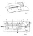
- the continuous sealer remains as before and in known Way with reference to Fig.1,2 from a in a flow guide 2 of the device arranged welding tool 3 for Detection and welding or sealing of the opening edges R of each passing bag VB and one in the End region of the flow guide 2 of the device housing 1 arranged Printing unit 4 for printing on the sealed opening edges R.
- the bags to be sealed and printed VB are still applied to the left of the device, from one Transport device TE detected and for sealing and printing transported. For this required heaters and Pressure or sealing rollers are denoted by the reference H and A Mistake.
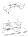
- the thermal print head 4 ' With regard to the fact that on the one hand in the thermal transfer printing process the surface to be printed and the ribbon 5 synchronously go through under the stationary arranged thermal print head 4 ', the tempered and preprogrammed "dots" of the Printhead with the passage speed brought to action and, on the other hand, unlike label printing when sealing the bag different degrees of sealing edges and can be incurred, but always the same, relatively weak contact pressure for color transfer must be complied with, there is an advantageous development in that the thermal print head 4 'with the thermal transfer ribbon 5 distanceable with respect to the plane of the flow guide 2 is arranged in the device housing 1. This distance adjustability moves on the order of only Millimeter fractions up to a few millimeters. This is not particularly illustrated and not especially to explain therefor corresponding constructive possibilities and Items readily available.
- the coils 6,6 ' are with their ribbon 5 in the form of a removable cassette 8, whose the coils 6,6 'enclosing cassette parts 8' by a the tangent of the coils 6,6 'and accumulating ribbon 5 leading web 9 are connected, in which a penetration window 10 for the pressure-active part of the thermal printhead 4 ' is arranged.
- To be able to make continuous sealing device is the device housing 1 in the field of printer and cartridge assembly with a provided lockable access opening 11, as shown in Fig.1 indicated by dashed lines.
- this programming panel 12 by reference on Fig.4 preferably as a separate accessory on the desk-like inclined front surface 13 of the device housing 1 is arranged is that also also on the service side with a display 14 to display the currently programmed print data is provided.
Abstract
Description
Die Erfindung betrifft ein Durchlaufsiegelgerät zum Schweißversiegeln der Öffnungsränder von mit Sterilgut gefüllten Verpackungsbeuteln aus verschweißbarer Kunststofffolie, bestehend aus einem in einer Durchlaufführung des Gerätes angeordneten Schweißwerkzeug zur Erfassung und Verschweißung der Öffnungsränder des jeweils passierenden Beutels und aus einem im Endbereich der Durchlaufführung des Gerätegehäuses angeordneten Druckwerkes zum Bedrucken der versiegelten Öffnungsränder.The invention relates to a continuous sealing device for welding the opening edges of filled with sterile goods packaging bags made of weldable plastic film, consisting from a arranged in a flow guide of the device Welding tool for detecting and welding the opening edges each passing bag and one in the end arranged the flow guide of the device housing Printing unit for printing on the sealed opening edges.
Durchlaufsiegelgeräte sind bspw. nach dem DE-A-296 10 976 U1 bekannt und sofern solche Geräte, wie einleitend angegeben, mit einem Drucker gemäß DE-A-200 19 799 U1 ausgestattet sind, handelt es sich bei diesen Druckern in Verbindung mit solchen speziellen Durchlaufsiegelgeräten, soweit bekannt, ausschließlich um sogenannte Nadeldruckwerke. Bei solchen Durchlaufsiegelgeräten handelt es sich ferner insofern um so genannte Halbautomaten, als dabei die gefüllten und zu versiegelnden Beutel von Hand in die seitlich offene Durchlaufführung angelegt und eingeschoben werden, in der dann unter Passage einer Folienvorheizung der Weitertransport mittels zweier Endlostransporte zwischen zwei Siegelrollen erfolgt, die die beiden benachbarten Öffnungsränder eines Beutels miteinander versiegeln. Daran schließt sich das Bedrucken des Siegelrandes bspw. mit inhaltsspezifischen Daten an, und zwar mittels des im Endbereich der Durchlaufführung im Gerätegehäuse mit angeordneten Nadeldruckers. Unter inhaltsspezifischen Daten sind dabei bspw. zu verstehen das Sterilisationsdatum, das Verfallsdatum, Chargennummer, sogenannte BAR-Codes und dgl. Daten. Continuous sealing devices are, for example, according to DE-A-296 10 976 U1 known and provided such devices, as stated in the introduction, with a printer according to DE-A-200 19 799 U1, is these printers are associated with such printers special continuous sealing devices, where known, exclusively to so-called dot-matrix printing. In such continuous sealing devices are so far in this respect so-called Semi-automatic machines, as doing the filled and to be sealed Bag applied by hand in the laterally open flow guide and be pushed in, then under passage one Foil preheating of the further transport by means of two endless transport between two sealing rolls, which are the two Seal adjacent opening edges of a bag together. This is followed by the printing of the sealing edge, for example. with content-specific data, by means of the in the end the flow guide in the device housing arranged with Dot-matrix printer. Under content-specific data are eg. to understand the sterilization date, expiration date, lot number, so-called BAR codes and the like. Data.
Derartige Durchlaufsiegelgeräte haben sich hinsichtlich des Bedruckens der Beutelsiegelränder als verbesserbar erwiesen, d.h., das Durchlaufsiegelgerät soll besser steuerbar sein, ein besseres Druckbild ergeben, variable Schriftgrößen und gewünschtenfalls auch den Druckübertrag von Graphikdarstellungen zulassen.Such Durchlaufsiegelgeräte have in terms of Printing the bag seal edges proved to be improvable that is, the flow-seal device should be more controllable produce better print image, variable font sizes and if desired also the pressure transfer of graphical representations allow.
Diese Aufgabe ist an Siegelgeräten der eingangs genannten Art nach der Erfindung dadurch gelöst, daß das Druckwerk aus einem programmierbaren Thermodruckkopf gebildet und dieser über einem parallel zur und unmittelbar über der Durchlaufführung geführten Thermotransfer-Farbband angeordnet und dieses Farbband von ebenfalls über der Durchlaufführung angeordneten Ab- und Auflaufspulen geführt ist, zwischen denen der Thermodruckkopf in Einwirkstellung zum Farbband angeordnet ist, wobei in der Durchlaufführung vor dem Thermodruckkopf ein mit diesem und dem Farbbandantrieb in steuerender Wirkverbindung stehender Siegelrandsensor angeordnet ist.This object is to sealing devices of the type mentioned solved according to the invention in that the printing unit from a Programmable thermal printhead and this one over parallel to and guided directly above the passage guide Thermal transfer ribbon arranged and this ribbon of also arranged on the pass guide Ab- and casserole coils is guided, between which the thermal print head in Einwirkstellung is arranged to the ribbon, wherein in the Pass guide in front of the thermal printhead with this and the Ribbon drive in controlling operative connection standing seal edge sensor is arranged.
Solche,für den sogenannten Thermotransferdruck bestimmte, programmierbare
Thermodrucker sind zwar bekannt, kommen aber, soweit
bekannt, insbesondere für den Etikettendruck zur Verwendung,
und zwar als separate Geräte, wobei die auf einem Trägerband
mit gleichem Abstand befindlichen und zugeführten Etiketten
fortlaufend mit den jeweils eingegebenen Daten durch
thermische Beaufschlagung des Farbbandes mittels sogenannter
"dots" bedruckt werden. Solche separaten Thermotransfer-Druckgeräte
sind auch schon Ausstattungsgegenstand von bspw. Packtischen
für die hier interessierende Sterilgutverpackung mittels
der vorerwähnten Durchlaufsiegelgeräte, wobei allerdings
die bedruckten Etiketten nach Ablösung von ihrem Trägerband auf
die Siegelränder der versiegelten Verpackungsbeutel oder was
auch immer übertragen werden müssen.
Einer unmittelbaren Übertragung dieser Thermotransferdruckmethode,
die zu hervorragenden und dauerhaft haltbaren Druckergebnissen
auch auf Kunststofffolien führt, auf Durchlaufsiegelgeräte
stand jedoch entgegen, daß es sich bei diesen Such, for the so-called thermal transfer printing certain, programmable thermal printer are known, but come, as far as known, in particular for label printing for use, as a separate device, the on a carrier tape with the same distance and supplied labels continuously with each entered Data are printed by thermal loading of the ink ribbon by means of so-called "dots". Such separate thermal transfer printing devices are also equipment of eg. Packing tables for the sterile packaging of interest here by means of the aforementioned continuous sealing devices, although the printed labels after removal from their carrier tape on the seal edges of the sealed packaging bag or whatever must be transmitted.
However, a direct transfer of this thermal transfer printing method, which leads to excellent and long-lasting print results on plastic films, on continuous sealers was contrary to that of these
Geräten, wie erwähnt, um sogenannte Halbautomaten handelt, bei denen also keine gleichmäßig kontinuierliche Zufuhr der zu bedruckenden Siegelränder zu verwirklichen ist. Abgesehen davon, war auch nicht ohne weiteres zu erwarten, daß sich das Thermotransfer-Druckverfahren erfolgreich auch dann anwenden läßt, wenn unter vorteilhafter Vermeidung einer Etikettenübertragung vom Siegelvorgang bereits erwärmte bzw. noch relativ warme Foliensiegelränder bedruckt werden sollen.Devices, as mentioned, are so-called semi-automatic, at which therefore not a uniform continuous supply of is to realize printing sealing edges. Apart from this, was not to be expected without further ado that the Successfully apply thermal transfer printing process leaves, if advantageously avoid label transfer already heated by the sealing process or still relatively warm foil seal edges to be printed.
Unter einem programmierbaren Thermodruckkopf ist also ein Druckkopf zu verstehen, mit dem die auf dem Farbband auf der druckerabgewandten Seite befindliche, per Wärme und einem gewissen Druck übertragbare Farbe bei in Druckkontakt befindlichen und per Programm am Druckkopf eingestellten Lettern, Zahlen oder auch sonstige Darstellungen auf die Siegelrandfläche des betreffenden Beutels wiedergabegenau übertragen wird. Der auf die gewünschten Daten eingestellte Druckkopf bzw. dessen sogenannten, individuell zur Wirkung bringbaren "dots" bildet also ein einfach programmierbares Druckmedium, das unter Zwischenschaltung des Farbbandes per Thermostransfer die eingestellten Daten überträgt, die, da gewissermaßen eingebrannt, auch unverwischbar ihre Wiedergabe auf den Siegelrändern finden.So under a programmable thermal print head is a Printhead to understand with the on the ribbon on the printer away side, by heat and a certain Pressure transferable color when in pressure contact and by program on the printhead set letters, Numbers or other representations on the sealing edge surface the bag in question is transmitted reproduction accurate. The printhead set to the desired data or its so-called "dots" that can be brought into action individually So forms an easily programmable print medium that under Interposition of the ribbon by Thermostransfer the set Transmits data that, as it were branded, indelibly find their reproduction on the seal edges.
Abgesehen von der mittels einer Eingabetastatur zu bewirkenden
einfachen Programmierung dessen, was gedruckt werden soll, ist
dabei das Gerät bzgl. des Weitertransportes des Farbbandes
einfach zu steuern und zwar in Übereinstimmung mit einem in der
Durchlaufführung ankommenden Siegelrand, welches Ankommen nicht
in gleichmäßigen Abständen erfolgt, da ja die zu versiegelnden
Beutel von Hand in das Siegelgerät eingegeben werden. Aus diesem
Grunde ist in der Durchlaufführung vor dem Thermodruckkopf
ein Siegelrandsensor angeordnet, der über die Gerätesteuerung
mit dem Transportantrieb für das Thermofarbband verschaltet ist
und gegf. geringfügig zeitversetzt den Thermotransfervorgang
beginnen läßt.
Im Gegensatz zum bisher praktizierten Thermotransferdruckverfahren,
das einen Synchronlauf von Farband, bspw. Etikettenband
und dazu synchronen Druckvorgang verlangt, und zwar im kontinuierlichen
Durchlauf, ist beim erfindungsgemäßen Durchlaufsiegelgerät
dafür gesorgt, daß diese Synchronizität nur für den
eigentlichen Druckvorgang am gerade den Druckkopf passierenden
Siegelrand gewährleistet ist.Apart from the simple programming of what is to be printed by means of an input keyboard, while the device with respect to the further transport of the ink ribbon is easy to control in accordance with an incoming in the flow guide sealing edge, which arrival is not evenly spaced, since the bags to be sealed by hand are entered into the sealing device. For this reason, a seal edge sensor is arranged in the flow guide in front of the thermal print head, which is connected via the device control with the transport drive for the thermal ribbon and gegf. slightly delayed start the thermal transfer process.
In contrast to the previously practiced thermal transfer printing process, which requires a synchronous operation of Farband, for example. Label tape and synchronous printing process, in a continuous run, it is ensured in the continuous sealing device according to the invention ensures that this synchronicity ensures only for the actual printing on the sealing edge passing just the print head is.
Ein Umstellen auf eine gegf. gewünschte andere Druckfarbe ist ohne weiteres durch Wechsel des Farbbandes zu bewerkstelligen. Um einen solchen Wechsel oder auch einen Austausch gegen ein neues Farbband so einfach wie möglich durchführen zu können, besteht eine bevorzugte, besonders vorteilhafte und im Einzelnen noch näher zu erläuternde Ausführungsform darin, daß die Spulen mit ihrem Farbband in Form einer auswechselbaren Kassette ausgebildet sind, deren die Spulen umschließenden Kassettenteile durch einen das tangential von den Spulen ab- und auflaufende Farbband führenden Steg verbunden sind, in dem ein Durchgriffsfenster für den druckaktiven Teil des Thermo-Druckkopfes angeordnet ist.A change to a gegf. desired other ink is to accomplish easily by changing the ribbon. To such a change or even an exchange against to carry out a new ribbon as simply as possible, There is a preferred, particularly advantageous and in detail to be explained in more detail embodiment in that the Coils with their ribbon in the form of a removable cassette are formed, the coil enclosing the cassette parts by a tangent of the coils off and Bounding ribbon leading web are connected in the one Pass-through window for the pressure-active part of the thermal print head is arranged.
Mit Rücksicht auf die einfache Kassettenaustauschbarkeit ist schließlich das Gerätegehäuse im Bereich der Drucker- und Kassettenanordnung mit einer verschließbaren Zugriffsöffnung versehen und außerdem mit einer Eingabetastatur für die Programmierung.With respect to the easy cassette interchangeability is Finally, the device housing in the area of the printer and cartridge assembly provided with a closable access opening and also with an input keyboard for programming.
Das erfindungsgemäße Siegelgerät wird nachfolgend anhand der zeichnerischen Darstellung von Ausführungsbeispielen näher erläutert.The sealing device according to the invention is described below with reference to Drawings of exemplary embodiments closer explained.
Es zeigt schematisch
- Fig.1
- perspektivisch ein Ausführungsbeispiel des DurchlaufSiegelgerätes;
- Fig.2
- schematisch einen Längsschnitt durch das Gerät;
- Fig.3
- perspektivisch eine Ausführungsform der Farbbandkassette und
- Fig.4
- perspektivisch eine bevorzugte Ausführungsform des Durchlauf-Siegelgerätes.
- Fig.1
- in perspective, an embodiment of the continuous sealing device;
- Fig.2
- schematically a longitudinal section through the device;
- Figure 3
- perspective view of an embodiment of the ribbon cassette and
- Figure 4
- in perspective, a preferred embodiment of the continuous sealing device.
Das Durchlaufsiegelgerät besteht nach wie vor und in bekannter
Weise unter Verweis auf die Fig.1,2 aus einem in einer Durchlaufführung
2 des Gerätes angeordneten Schweißwerkzeug 3 zur
Erfassung und Verschweißung bzw. Versiegelung der Öffnungsränder
R des jeweils passierenden Beutels VB und aus einem im
Endbereich der Durchlaufführung 2 des Gerätegehäuses 1 angeordneten
Druckwerk 4 zum Bedrucken der versiegelten Öffnungsränder
R. Die zu versiegelnden und zu bedruckenden Beutel VB
werden dabei nach wie vor links am Gerät angelegt, von einer
Transporteinrichtung TE erfaßt und zum Versiegeln und Bedrucken
weitertransportiert. Dafür erforderliche Heizeinrichtungen und
Andruck- bzw. Siegelrollen sind mit den Bezugszeichen H und A
versehen.The continuous sealer remains as before and in known
Way with reference to Fig.1,2 from a in a
Für ein solches Durchlaufsiegelgerät ist nun wesentlich, daß
das Druckwerk 4 aus einem programmierbaren Thermodruckkopf 4'
gebildet und dieser über einem parallel zur und unmittelbar
über der Durchlaufführung 2 geführten Thermotransfer-Farbband 5
angeordnet. Dieses Farbband 5 ist dabei von ebenfalls über der
Durchlaufführung 2 angeordneten Ab- und Auflaufspulen 6,6' geführt,
zwischen denen der Thermodruckkopf 4' in Einwirkstellung
zum Farbband 5 angeordnet ist, wobei in der Durchlaufführung 2
vor dem Thermodruckkopf 4' ein mit diesem und dem Farbbandantrieb
(nicht besonders dargestellt) in steuerender Wirkverbindung
stehender Siegelrandsensor 7 angeordnet ist.For such a continuous sealing device is now essential that
the
Dieser via Gerätesteuerung 12 (siehe Fig.2) mit dem Farbbandantrieb
verschaltete Sensor 7 sorgt dafür, daß für den ankommenden
Beutel bzw. Siegelrand R ein unverbrauchter, neuer
Farbbandabschnitt zur Verfügung steht, der sich an den vorgelaufenen,
verbrauchten Abschnitt so dicht wie möglich anschließt.This via device control 12 (see Figure 2) with the ribbon drive
interconnected
Mit Rücksicht darauf, daß zum Einen beim Thermotransfer-Druckverfahren
die zu bedruckende Fläche und das Farbband 5 synchron
unter dem stationär angeordneten Thermodruckkopf 4' durchlaufen,
wobei die temperierten und vorprogrammierten "dots" des
Druckkopfes mit der Durchlaufgeschwindigkeit zur Wirkung gebracht
werden, und daß zum Anderen im Gegensatz zum Etikettendruck
beim Beutelversiegeln unterschiedlich starke Siegelränder
anfallen können und zu bedrucken sind, wobei aber immer
der gleiche, relativ schwache Kontaktdruck für den Farbtransfer
eingehalten sein muß, besteht eine vorteilhafte Weiterbildung
darin, daß der Thermodruckkopf 4' mit dem Thermotransfer-Farbband
5 in Bezug auf die Ebene der Durchlaufführung 2 distanzeinstellbar
im Gerätegehäuse 1 angeordnet ist. Diese Distanzeinstellbarkeit
bewegt sich dabei in der Größenordnung von nur
Millimeterbruchteilen bis zu wenigen Millimetern. Dies ist
nicht besonders dargestellt und auch nicht beonders zu erläutern,
da dafür entsprechend konstruktive Möglichkeiten und
Elemente ohne weiteres zur Verfügung stehen.With regard to the fact that on the one hand in the thermal transfer printing process
the surface to be printed and the
Unter Verweis auf Fig.3 sind die Spulen 6,6' mit ihrem Farbband
5 in Form einer auswechselbaren Kassette 8 ausgebildet, deren
die Spulen 6,6' umschließenden Kassettenteile 8' durch einen
das tangential von den Spulen 6,6' ab- und auflaufende Farbband
5 führenden Steg 9 verbunden sind, in dem ein Durchgriffsfenster
10 für den druckaktiven Teil des Thermo-Druckkopfes 4'
angeordnet ist.Referring to Fig. 3, the
Um einen Farbbandwechsel oder -austausch komplikationslos am
Durchlaufsiegelgerät vornehmen zu können, ist das Gerätegehäuse
1 im Bereich der Drucker- und Kassettenanordnung mit einer
verschließbaren Zugriffsöffnung 11 versehen, wie dies in Fig.1
gestrichelt angedeutet ist.To a ribbon change or exchange without complications on
To be able to make continuous sealing device is the
Mit Rücksicht auf den programmierbaren Thermodruckkopf 4' ist
das Gerätegehäuse 1 bedienseitig mit einem Programmiertableau
12 versehen, wobei dieses Programmiertableau 12 unter Verweis
auf Fig.4 vorzugsweise als separates Zubehörteil auf der pultartig
geneigten Frontfläche 13 des Gerätegehäuses 1 angeordnet
ist, das außerdem ebenfalls bedienseitig mit einem Display 14
zur Darstellung der jeweils programmierten aktuellen Druckdaten
versehen ist.With regard to the programmable thermal printhead 4 '
the device housing 1 operator side with a
Claims (7)
dadurch gekennzeichnet, daß das Druckwerk (4) aus einem programmierbaren Thermodruckkopf (4') gebildet und dieser über einem parallel zur und unmittelbar über der Durchlaufführung (2) geführten Thermotransfer-Farbband (5) angeordnet und dieses Farbband (5) von ebenfalls über der Durchlaufführung (2) angeordneten Ab- und Auflaufspulen (6,6') geführt ist, zwischen denen der Thermodruckkopf (4') in Einwirkstellung zum Farbband (5) angeordnet ist, wobei in der Durchlaufführung (2) vor dem Thermodruckkopf (4') ein mit diesem und dem Farbbandantrieb in steuerender Wirkverbindung stehender Siegelrandsensor (7) angeordnet ist.Continuous sealer for sealing the opening edges (R) of sterile-filled packaging bags (VB) of weldable plastic film, consisting of a in a flow guide (2) of the device arranged welding tool (3) for detecting and welding the opening edges (R) of each passing bag ( VB) and from a in the end region of the flow guide (2) of the device housing (1) arranged printing unit (4) for printing the sealed opening edges (R),
characterized in that the printing unit (4) from a programmable thermal print head (4 ') formed and this over a parallel to and immediately above the pass guide (2) guided thermal transfer ribbon (5) and arranged this ribbon (5) also on the Passing guide (2) arranged Ab- and Auflaufspulen (6,6 ') is guided, between which the thermal print head (4') in Einwirkstellung to the ink ribbon (5) is arranged, wherein in the pass guide (2) in front of the thermal print head (4 ') a sealing edge sensor (7) which is in controllable operative connection with this and the ribbon drive is arranged.
dadurch gekennzeichnet, daß der Thermodruckkopf (4') mit dem Thermotransfer-Farbband (5) in Bezug auf die Ebene der Durchlaufführung (2) distanzeinstellbar im Gerätegehäuse (1) angeordnet ist.Continuous sealing device according to claim 1,
characterized in that the thermal print head (4 ') with the thermal transfer ribbon (5) with respect to the plane of the flow guide (2) is arranged distanzeinstellbar in the device housing (1).
dadurch gekennzeichnet, daß die Spulen (6,6') mit ihrem Farbband (5) in Form einer auswechselbaren Kassette (8) ausgebildet sind, deren die Spulen (6,6') umschließenden Kassettenteile (8') durch einen das tangential von den Spulen (6,6') ab- und auflaufende Farbband (5) führenden Steg (9) verbunden sind, in dem ein Durchgriffsfenster (10) für den druckaktiven Teil des Druckkopfes (4') angeordnet ist. Continuous sealing device according to claim 1 or 2,
characterized in that the coils (6, 6 ') are formed with their ink ribbon (5) in the form of an exchangeable cassette (8) whose parts (8, 6') surround the coils (6, 6 ') by a tangential one of the cassettes Coils (6,6 ') and emerging ribbon (5) leading web (9) are connected, in which a penetration window (10) for the pressure-active part of the print head (4') is arranged.
dadurch gekennzeichnet, daß das Gerätegehäuse (1) im Bereich der Drucker- und Kassettenanordnung mit einer verschließbaren Zugriffsöffnung (11) versehen ist.Continuous sealing device according to one of claims 1 to 3,
characterized in that the device housing (1) is provided in the region of the printer and cartridge assembly with a closable access opening (11).
dadurch gekennzeichnet, daß das Gerätegehäuse (1) bedienseitig mit einem Programmiertableau (12) für den Thermodruckkopf (4') versehen ist.Continuous sealing device according to one of claims 1 to 4,
characterized in that the device housing (1) on the operating side with a programming panel (12) for the thermal print head (4 ') is provided.
dadurch gekennzeichnet, daß das Programmiertableau (12) als separates Zubehörteil auf der pultartig geneigten Frontfläche (13) des Gerätegehäuses (1) angeordnet ist.Continuous sealing device according to claim 5,
characterized in that the programming panel (12) is arranged as a separate accessory on the desk-like inclined front surface (13) of the device housing (1).
dadurch gekennzeichnet, daß das Gerätegehäuse (1) bedienseitig mit einem Display (14) zur Darstellung der jeweils programmierten Druckdaten versehen ist.A continuous sealer according to any one of claims 1 to 6,
characterized in that the device housing (1) is provided on the operating side with a display (14) for displaying the respectively programmed pressure data.
Applications Claiming Priority (2)
| Application Number | Priority Date | Filing Date | Title |
|---|---|---|---|
| DE202004008007U | 2004-05-18 | ||
| DE202004008007U DE202004008007U1 (en) | 2004-05-18 | 2004-05-18 | Rotary Sealer |
Publications (3)
| Publication Number | Publication Date |
|---|---|
| EP1598277A2 true EP1598277A2 (en) | 2005-11-23 |
| EP1598277A3 EP1598277A3 (en) | 2006-01-04 |
| EP1598277B1 EP1598277B1 (en) | 2007-07-25 |
Family
ID=33154725
Family Applications (1)
| Application Number | Title | Priority Date | Filing Date |
|---|---|---|---|
| EP05010103A Active EP1598277B1 (en) | 2004-05-18 | 2005-05-10 | Fed through sealing apparatus |
Country Status (2)
| Country | Link |
|---|---|
| EP (1) | EP1598277B1 (en) |
| DE (1) | DE202004008007U1 (en) |
Cited By (6)
| Publication number | Priority date | Publication date | Assignee | Title |
|---|---|---|---|---|
| FR2946026A1 (en) * | 2009-05-28 | 2010-12-03 | Labo Electrofrance | Continuous winding integrated heat sealing machine for closing sachet i.e. sterilization type sachet, in e.g. medical field, has crushing pulley whose diameter is greater than diameter of marking pulley |
| CN104552923A (en) * | 2013-08-08 | 2015-04-29 | 通用汽车环球科技运作有限责任公司 | Systems and methods for joining polymeric composites using conductive ink and conductive rivet |
| CN108773189A (en) * | 2018-06-11 | 2018-11-09 | 包旭红 | A kind of thermocompression bonding film coder with the double print cartridge functions of primary and secondary |
| CN110481895A (en) * | 2019-08-26 | 2019-11-22 | 河北今旭面业有限公司 | A kind of film seal device |
| CN113320780A (en) * | 2021-06-04 | 2021-08-31 | 黑龙江省宝泉岭农垦山林粮食加工有限责任公司 | Online ink jet numbering machine |
| DE102017003972B4 (en) | 2016-04-27 | 2023-02-23 | Entrhal Medical Gmbh | Sealing device with interchangeable unit |
Families Citing this family (4)
| Publication number | Priority date | Publication date | Assignee | Title |
|---|---|---|---|---|
| DE202005004647U1 (en) * | 2005-03-20 | 2006-08-03 | Wolf, Hans | Sealing device, sterile goods packaging bag and storage room for sterile goods packaging bags |
| DE202005005126U1 (en) | 2005-03-29 | 2006-08-10 | Wolf, Hans | sealer |
| SE541463C2 (en) * | 2017-10-06 | 2019-10-08 | Sealwacs Ab | Plastic welding sensor |
| DE102018126488A1 (en) * | 2018-10-24 | 2019-08-14 | hawo - Gerätebau GmbH & Co. Maschinenbau KG. | Rotary Sealer |
Citations (6)
| Publication number | Priority date | Publication date | Assignee | Title |
|---|---|---|---|---|
| US5560595A (en) * | 1994-10-28 | 1996-10-01 | Pitney Bowes Inc. | Envelope ejection speed control system and method |
| EP0802117A1 (en) * | 1996-04-19 | 1997-10-22 | Daisey Kikai Co., Ltd. | Line thermal printer head |
| DE29916381U1 (en) * | 1999-09-17 | 2000-01-27 | Getinge Van Dijk Medizintechni | Sealing device with label printer |
| US6285387B1 (en) * | 1999-08-31 | 2001-09-04 | Nisca Corporation | Recording device |
| EP1211179A1 (en) * | 2000-11-21 | 2002-06-05 | Hans Wolf | Sealing device |
| US20040079243A1 (en) * | 2002-05-16 | 2004-04-29 | British American Tobacco (Germany) Gmbh | Device and method for marking cigarette packets |
Family Cites Families (3)
| Publication number | Priority date | Publication date | Assignee | Title |
|---|---|---|---|---|
| JPS5917957A (en) * | 1982-07-20 | 1984-01-30 | Shizuoka Seiki Co Ltd | Rice-bagger with device for printing proper quantity of water for boiling rice |
| JP3669817B2 (en) * | 1997-06-02 | 2005-07-13 | 株式会社大生機械 | Line thermal head printer |
| JP2000128134A (en) * | 1998-10-26 | 2000-05-09 | Marutsune:Kk | Sealing device |
-
2004
- 2004-05-18 DE DE202004008007U patent/DE202004008007U1/en not_active Expired - Lifetime
-
2005
- 2005-05-10 EP EP05010103A patent/EP1598277B1/en active Active
Patent Citations (6)
| Publication number | Priority date | Publication date | Assignee | Title |
|---|---|---|---|---|
| US5560595A (en) * | 1994-10-28 | 1996-10-01 | Pitney Bowes Inc. | Envelope ejection speed control system and method |
| EP0802117A1 (en) * | 1996-04-19 | 1997-10-22 | Daisey Kikai Co., Ltd. | Line thermal printer head |
| US6285387B1 (en) * | 1999-08-31 | 2001-09-04 | Nisca Corporation | Recording device |
| DE29916381U1 (en) * | 1999-09-17 | 2000-01-27 | Getinge Van Dijk Medizintechni | Sealing device with label printer |
| EP1211179A1 (en) * | 2000-11-21 | 2002-06-05 | Hans Wolf | Sealing device |
| US20040079243A1 (en) * | 2002-05-16 | 2004-04-29 | British American Tobacco (Germany) Gmbh | Device and method for marking cigarette packets |
Non-Patent Citations (3)
| Title |
|---|
| PATENT ABSTRACTS OF JAPAN Bd. 008, Nr. 102 (C-222), 12. Mai 1984 (1984-05-12) & JP 59 017957 A (SHIZUOKA SEIKI KK), 30. Januar 1984 (1984-01-30) * |
| PATENT ABSTRACTS OF JAPAN Bd. 1999, Nr. 03, 31. März 1999 (1999-03-31) & JP 10 329344 A (TAISEI KIKAI:KK), 15. Dezember 1998 (1998-12-15) * |
| PATENT ABSTRACTS OF JAPAN Bd. 2000, Nr. 08, 6. Oktober 2000 (2000-10-06) & JP 2000 128134 A (MARUTSUNE:KK), 9. Mai 2000 (2000-05-09) * |
Cited By (8)
| Publication number | Priority date | Publication date | Assignee | Title |
|---|---|---|---|---|
| FR2946026A1 (en) * | 2009-05-28 | 2010-12-03 | Labo Electrofrance | Continuous winding integrated heat sealing machine for closing sachet i.e. sterilization type sachet, in e.g. medical field, has crushing pulley whose diameter is greater than diameter of marking pulley |
| CN104552923A (en) * | 2013-08-08 | 2015-04-29 | 通用汽车环球科技运作有限责任公司 | Systems and methods for joining polymeric composites using conductive ink and conductive rivet |
| CN104552923B (en) * | 2013-08-08 | 2017-11-17 | 通用汽车环球科技运作有限责任公司 | With conductive black liquid and the system and method for conductive rivet connection polymer composites |
| DE102017003972B4 (en) | 2016-04-27 | 2023-02-23 | Entrhal Medical Gmbh | Sealing device with interchangeable unit |
| CN108773189A (en) * | 2018-06-11 | 2018-11-09 | 包旭红 | A kind of thermocompression bonding film coder with the double print cartridge functions of primary and secondary |
| CN110481895A (en) * | 2019-08-26 | 2019-11-22 | 河北今旭面业有限公司 | A kind of film seal device |
| CN110481895B (en) * | 2019-08-26 | 2021-11-09 | 河北今旭面业有限公司 | Film sealing device |
| CN113320780A (en) * | 2021-06-04 | 2021-08-31 | 黑龙江省宝泉岭农垦山林粮食加工有限责任公司 | Online ink jet numbering machine |
Also Published As
| Publication number | Publication date |
|---|---|
| EP1598277B1 (en) | 2007-07-25 |
| DE202004008007U1 (en) | 2004-10-07 |
| EP1598277A3 (en) | 2006-01-04 |
Similar Documents
| Publication | Publication Date | Title |
|---|---|---|
| EP1598277A2 (en) | Fed through sealing apparatus | |
| DE3153377C2 (en) | LABEL PRINTER | |
| DE3316065C2 (en) | Process for filling, venting and sealing bags | |
| DE60122199T2 (en) | FEEDING AND LOADING DEVICE FOR A CONTINUOUS BELT WITH INTERGRATED PRESSURE ARRANGEMENT | |
| DE19824797B4 (en) | Bag manufacturing apparatus and method for manufacturing foil bags | |
| DE60015912T2 (en) | Method for packaging products | |
| DE102008007752A1 (en) | Method and device for producing (tobacco) bags | |
| DE2930963A1 (en) | PACKING DEVICE | |
| EP0179977B1 (en) | Method and apparatus for the thermal embossing of a substrate | |
| DE2943876C2 (en) | Printing facility | |
| DE2909348C2 (en) | ||
| EP0240827A1 (en) | Device for the production of air cushion mailing bags | |
| DE3332992A1 (en) | PRINTER WITH MOSAIC PRINT HEADS | |
| DE2647556C3 (en) | Device for multi-lane application of adhesive labels | |
| DE202007011960U1 (en) | Device for transferring transfer images to a product | |
| DE19618175C1 (en) | Equipment replacing first strip with second in packing machine | |
| DE3935345A1 (en) | Printing on products using thermal transfer printing unit - selectively heating transfer rods as band carrying ink runs by for transfer to intermediate band | |
| DE102004063348A1 (en) | Personalizing process for drink crates involves supplying crate to be personalized, and applying personalized foil to at least one outer wall of crate | |
| DE3118050C2 (en) | Stationary labeling device | |
| DE1244044B (en) | Device for closing plastic bags | |
| DE19542289B4 (en) | Sealing element and method and apparatus for its application to a beverage container | |
| DE544433C (en) | Pay card punching machine | |
| DE3545516A1 (en) | PACKING MACHINE | |
| EP2684806B1 (en) | Applicator device | |
| DE7415354U (en) | Device for labeling packaging bags on a bag closing device |
Legal Events
| Date | Code | Title | Description |
|---|---|---|---|
| PUAI | Public reference made under article 153(3) epc to a published international application that has entered the european phase |
Free format text: ORIGINAL CODE: 0009012 |
|
| PUAL | Search report despatched |
Free format text: ORIGINAL CODE: 0009013 |
|
| AK | Designated contracting states |
Kind code of ref document: A2 Designated state(s): AT BE BG CH CY CZ DE DK EE ES FI FR GB GR HU IE IS IT LI LT LU MC NL PL PT RO SE SI SK TR |
|
| AX | Request for extension of the european patent |
Extension state: AL BA HR LV MK YU |
|
| AK | Designated contracting states |
Kind code of ref document: A3 Designated state(s): AT BE BG CH CY CZ DE DK EE ES FI FR GB GR HU IE IS IT LI LT LU MC NL PL PT RO SE SI SK TR |
|
| AX | Request for extension of the european patent |
Extension state: AL BA HR LV MK YU |
|
| 17P | Request for examination filed |
Effective date: 20060330 |
|
| AKX | Designation fees paid |
Designated state(s): FR IT NL SE |
|
| REG | Reference to a national code |
Ref country code: DE Ref legal event code: 8566 |
|
| GRAP | Despatch of communication of intention to grant a patent |
Free format text: ORIGINAL CODE: EPIDOSNIGR1 |
|
| GRAS | Grant fee paid |
Free format text: ORIGINAL CODE: EPIDOSNIGR3 |
|
| GRAA | (expected) grant |
Free format text: ORIGINAL CODE: 0009210 |
|
| AK | Designated contracting states |
Kind code of ref document: B1 Designated state(s): FR IT NL SE |
|
| REG | Reference to a national code |
Ref country code: SE Ref legal event code: TRGR |
|
| ET | Fr: translation filed | ||
| PLBE | No opposition filed within time limit |
Free format text: ORIGINAL CODE: 0009261 |
|
| STAA | Information on the status of an ep patent application or granted ep patent |
Free format text: STATUS: NO OPPOSITION FILED WITHIN TIME LIMIT |
|
| 26N | No opposition filed |
Effective date: 20080428 |
|
| REG | Reference to a national code |
Ref country code: FR Ref legal event code: PLFP Year of fee payment: 11 |
|
| REG | Reference to a national code |
Ref country code: FR Ref legal event code: PLFP Year of fee payment: 12 |
|
| REG | Reference to a national code |
Ref country code: FR Ref legal event code: PLFP Year of fee payment: 13 |
|
| REG | Reference to a national code |
Ref country code: FR Ref legal event code: PLFP Year of fee payment: 14 |
|
| PGFP | Annual fee paid to national office [announced via postgrant information from national office to epo] |
Ref country code: NL Payment date: 20220310 Year of fee payment: 18 |
|
| PGFP | Annual fee paid to national office [announced via postgrant information from national office to epo] |
Ref country code: FR Payment date: 20220530 Year of fee payment: 18 |
|
| PGFP | Annual fee paid to national office [announced via postgrant information from national office to epo] |
Ref country code: SE Payment date: 20230310 Year of fee payment: 19 |
|
| REG | Reference to a national code |
Ref country code: NL Ref legal event code: MM Effective date: 20230601 |
|
| PGFP | Annual fee paid to national office [announced via postgrant information from national office to epo] |
Ref country code: IT Payment date: 20231124 Year of fee payment: 19 |
|
| PG25 | Lapsed in a contracting state [announced via postgrant information from national office to epo] |
Ref country code: NL Free format text: LAPSE BECAUSE OF NON-PAYMENT OF DUE FEES Effective date: 20230601 |