EP1603473B1 - Electrical needle with radiopaque marker - Google Patents
Electrical needle with radiopaque marker Download PDFInfo
- Publication number
- EP1603473B1 EP1603473B1 EP04717535.1A EP04717535A EP1603473B1 EP 1603473 B1 EP1603473 B1 EP 1603473B1 EP 04717535 A EP04717535 A EP 04717535A EP 1603473 B1 EP1603473 B1 EP 1603473B1
- Authority
- EP
- European Patent Office
- Prior art keywords
- needle
- shaft
- radiopaque
- stylet
- tip
- Prior art date
- Legal status (The legal status is an assumption and is not a legal conclusion. Google has not performed a legal analysis and makes no representation as to the accuracy of the status listed.)
- Expired - Lifetime
Links
- 239000003550 marker Substances 0.000 title claims description 16
- 238000000576 coating method Methods 0.000 claims description 17
- 239000011248 coating agent Substances 0.000 claims description 16
- 239000000523 sample Substances 0.000 claims description 8
- 238000003780 insertion Methods 0.000 claims description 5
- 230000037431 insertion Effects 0.000 claims description 5
- 238000012800 visualization Methods 0.000 claims description 4
- 238000000034 method Methods 0.000 description 12
- 239000000463 material Substances 0.000 description 9
- 229910052751 metal Inorganic materials 0.000 description 7
- 239000002184 metal Substances 0.000 description 7
- 210000001519 tissue Anatomy 0.000 description 6
- 208000002193 Pain Diseases 0.000 description 4
- 230000003902 lesion Effects 0.000 description 4
- 229920000642 polymer Polymers 0.000 description 4
- 238000007740 vapor deposition Methods 0.000 description 4
- 238000005286 illumination Methods 0.000 description 3
- 238000005468 ion implantation Methods 0.000 description 3
- 150000002739 metals Chemical class 0.000 description 3
- 230000001537 neural effect Effects 0.000 description 3
- 238000012795 verification Methods 0.000 description 3
- 208000008035 Back Pain Diseases 0.000 description 2
- 238000002594 fluoroscopy Methods 0.000 description 2
- 238000010438 heat treatment Methods 0.000 description 2
- 238000010849 ion bombardment Methods 0.000 description 2
- 210000005036 nerve Anatomy 0.000 description 2
- BASFCYQUMIYNBI-UHFFFAOYSA-N platinum Chemical compound [Pt] BASFCYQUMIYNBI-UHFFFAOYSA-N 0.000 description 2
- WFKWXMTUELFFGS-UHFFFAOYSA-N tungsten Chemical compound [W] WFKWXMTUELFFGS-UHFFFAOYSA-N 0.000 description 2
- 229910052721 tungsten Inorganic materials 0.000 description 2
- 239000010937 tungsten Substances 0.000 description 2
- 208000003618 Intervertebral Disc Displacement Diseases 0.000 description 1
- 208000031481 Pathologic Constriction Diseases 0.000 description 1
- BQCADISMDOOEFD-UHFFFAOYSA-N Silver Chemical compound [Ag] BQCADISMDOOEFD-UHFFFAOYSA-N 0.000 description 1
- 229910045601 alloy Inorganic materials 0.000 description 1
- 239000000956 alloy Substances 0.000 description 1
- 210000004556 brain Anatomy 0.000 description 1
- 230000015271 coagulation Effects 0.000 description 1
- 238000005345 coagulation Methods 0.000 description 1
- 238000002788 crimping Methods 0.000 description 1
- 230000006378 damage Effects 0.000 description 1
- 238000003618 dip coating Methods 0.000 description 1
- 239000003814 drug Substances 0.000 description 1
- 230000009977 dual effect Effects 0.000 description 1
- 238000009713 electroplating Methods 0.000 description 1
- -1 golf Chemical compound 0.000 description 1
- 238000007689 inspection Methods 0.000 description 1
- 229910052741 iridium Inorganic materials 0.000 description 1
- GKOZUEZYRPOHIO-UHFFFAOYSA-N iridium atom Chemical compound [Ir] GKOZUEZYRPOHIO-UHFFFAOYSA-N 0.000 description 1
- 238000012986 modification Methods 0.000 description 1
- 230000004048 modification Effects 0.000 description 1
- 230000000149 penetrating effect Effects 0.000 description 1
- 230000035515 penetration Effects 0.000 description 1
- 238000007747 plating Methods 0.000 description 1
- 229910052697 platinum Inorganic materials 0.000 description 1
- HWLDNSXPUQTBOD-UHFFFAOYSA-N platinum-iridium alloy Chemical compound [Ir].[Pt] HWLDNSXPUQTBOD-UHFFFAOYSA-N 0.000 description 1
- 239000000843 powder Substances 0.000 description 1
- 229910052709 silver Inorganic materials 0.000 description 1
- 239000004332 silver Substances 0.000 description 1
- 210000004872 soft tissue Anatomy 0.000 description 1
- 229910000679 solder Inorganic materials 0.000 description 1
- 230000036262 stenosis Effects 0.000 description 1
- 208000037804 stenosis Diseases 0.000 description 1
- 229910052715 tantalum Inorganic materials 0.000 description 1
- GUVRBAGPIYLISA-UHFFFAOYSA-N tantalum atom Chemical compound [Ta] GUVRBAGPIYLISA-UHFFFAOYSA-N 0.000 description 1
- 229940124597 therapeutic agent Drugs 0.000 description 1
- 230000000451 tissue damage Effects 0.000 description 1
- 231100000827 tissue damage Toxicity 0.000 description 1
Images


Classifications
-
- A—HUMAN NECESSITIES
- A61—MEDICAL OR VETERINARY SCIENCE; HYGIENE
- A61B—DIAGNOSIS; SURGERY; IDENTIFICATION
- A61B18/00—Surgical instruments, devices or methods for transferring non-mechanical forms of energy to or from the body
- A61B18/04—Surgical instruments, devices or methods for transferring non-mechanical forms of energy to or from the body by heating
- A61B18/12—Surgical instruments, devices or methods for transferring non-mechanical forms of energy to or from the body by heating by passing a current through the tissue to be heated, e.g. high-frequency current
- A61B18/14—Probes or electrodes therefor
- A61B18/1477—Needle-like probes
-
- A—HUMAN NECESSITIES
- A61—MEDICAL OR VETERINARY SCIENCE; HYGIENE
- A61N—ELECTROTHERAPY; MAGNETOTHERAPY; RADIATION THERAPY; ULTRASOUND THERAPY
- A61N1/00—Electrotherapy; Circuits therefor
- A61N1/02—Details
- A61N1/04—Electrodes
- A61N1/06—Electrodes for high-frequency therapy
-
- A—HUMAN NECESSITIES
- A61—MEDICAL OR VETERINARY SCIENCE; HYGIENE
- A61N—ELECTROTHERAPY; MAGNETOTHERAPY; RADIATION THERAPY; ULTRASOUND THERAPY
- A61N1/00—Electrotherapy; Circuits therefor
- A61N1/40—Applying electric fields by inductive or capacitive coupling ; Applying radio-frequency signals
-
- A—HUMAN NECESSITIES
- A61—MEDICAL OR VETERINARY SCIENCE; HYGIENE
- A61B—DIAGNOSIS; SURGERY; IDENTIFICATION
- A61B90/00—Instruments, implements or accessories specially adapted for surgery or diagnosis and not covered by any of the groups A61B1/00 - A61B50/00, e.g. for luxation treatment or for protecting wound edges
- A61B90/39—Markers, e.g. radio-opaque or breast lesions markers
- A61B2090/3966—Radiopaque markers visible in an X-ray image
-
- A—HUMAN NECESSITIES
- A61—MEDICAL OR VETERINARY SCIENCE; HYGIENE
- A61B—DIAGNOSIS; SURGERY; IDENTIFICATION
- A61B90/00—Instruments, implements or accessories specially adapted for surgery or diagnosis and not covered by any of the groups A61B1/00 - A61B50/00, e.g. for luxation treatment or for protecting wound edges
- A61B90/39—Markers, e.g. radio-opaque or breast lesions markers
-
- A—HUMAN NECESSITIES
- A61—MEDICAL OR VETERINARY SCIENCE; HYGIENE
- A61N—ELECTROTHERAPY; MAGNETOTHERAPY; RADIATION THERAPY; ULTRASOUND THERAPY
- A61N1/00—Electrotherapy; Circuits therefor
- A61N1/18—Applying electric currents by contact electrodes
- A61N1/32—Applying electric currents by contact electrodes alternating or intermittent currents
- A61N1/36—Applying electric currents by contact electrodes alternating or intermittent currents for stimulation
- A61N1/36014—External stimulators, e.g. with patch electrodes
- A61N1/36017—External stimulators, e.g. with patch electrodes with leads or electrodes penetrating the skin
-
- A—HUMAN NECESSITIES
- A61—MEDICAL OR VETERINARY SCIENCE; HYGIENE
- A61N—ELECTROTHERAPY; MAGNETOTHERAPY; RADIATION THERAPY; ULTRASOUND THERAPY
- A61N1/00—Electrotherapy; Circuits therefor
- A61N1/18—Applying electric currents by contact electrodes
- A61N1/32—Applying electric currents by contact electrodes alternating or intermittent currents
- A61N1/36—Applying electric currents by contact electrodes alternating or intermittent currents for stimulation
- A61N1/36014—External stimulators, e.g. with patch electrodes
- A61N1/36021—External stimulators, e.g. with patch electrodes for treatment of pain
Definitions
- the invention relates to a needle that delivers electrical current and more particularly to a needle that delivers high frequency electrical current in the vicinity of a neural structure.
- a minimally invasive technique of delivering high frequency electrical current has shown to relieve localized pain in many patients.
- the high frequency electrical current is typically delivered from a generator via connected electrodes that are placed in a patient's body.
- the needles include an insulated shaft with an exposed electrically conductive tip. Tissue resistance to the high frequency electrical current at the tip causes heating of adjacent tissue. When temperature increases sufficiently tissue coagulates. The temperature that is sufficient to coagulate unmyelinated nerve structures is 45 °C, at which point a lesion is formed and pain signals are blocked. This results in relief from pain.
- the exposed tip of the needle can be pointed, blunt and rounded or open, varying in shape in accordance with the needs of different procedures. Pointed tips are self-penetrating while rounded tips are useful in soft tissue areas such as the brain where it is critical not to damage nerves. However, blunt needles can do more tissue damage than small diameter sharp needles. Open tips can be used to deliver a therapeutic agent during electrical treatment.
- United States Patent No. 6,146,380 to Racz et al. describes electrical needles with curved tips used in high frequency lesioning.
- the needle having a hollow shaft and a removable stylet therein is inserted into the patient's body and positioned. Once the needle is positioned, the stylet is withdrawn and a distal end of a high frequency probe is inserted until the distal end of the probe is at least flush with the distal end of the shaft, (i.e. the exposed tip).
- the probe is connected to an external signal generator that generates high frequency electrical current.
- Radiopaque marking has been used to accomplish precise placement of catheters and stents.
- United States Patent No. 5,429,597 to Demello et al. discloses a balloon catheter having a radiopaque distal tip composed of a polymer mixed with a radiopaque powder such as tungsten.
- United States Patent No. 6,315,790 to Gerberding et al. describes a catheter constructed with radiopaque polymer hubs where the hubs provided the dual function of stent crimping and marker bands.
- WO 02/054941 discloses a needle with the features of the preamble of claim 1. Another needle is disclosed in WO 02/089686 .
- a needle for insertion into a patient's body for delivering high frequency electrical current as set forth in claim 1.
- the present invention provides for improved placement of a needle delivering high frequency energy by incorporating a radiopaque marker to distinguish the exposed tip from the shaft under fluoroscopic visualization.
- the tip is distinguishable from the rest of the needle when viewed under X-rays and fluoroscopy.
- a needle with radiopaque marking according to the present invention, is inserted in the patient's body, the location of a lesion made or to be made by the needle can be easily determined, as the tip of the needle can be distinguished from the electrically insulated shaft.
- the present invention provides a needle for insertion into a patient's body comprising an electrically insulated shaft having an electrically conductive tip portion and a radiopaque marker.
- the tip portion of the needle is the exposed tip and can be of varying dimensions.
- the radiopaque marker distinguishes the electrically insulated portion of the needle from the tip portion. This effectively identifies the position of the needle when in the body.
- the marker may be adapted to needles having various geometric shapes.
- the insulated portion of the needle includes an insulating coating. The coating may cover the radiopaque marker on the needle preventing a departure from the needle's true profile.
- the radiopaque marker is band-shaped and can comprise radiopaque coatings of metals/polymers, or radiopaque materials deposited on the surface of the needle by techniques such as ion implantation or vapor deposition.
- a medical apparatus for delivering high frequency electrical current to neural structures.
- the medical apparatus comprises a generator 100 for producing high frequency electrical current, a needle 102 with an electrical probe 110 connected to the generator 100 that is placed in the needle 102 for delivering the high frequency electrical current and a reference electrode 101 that completes the circuit.
- the needle 102 with the probe 110 is placed in a portion of a patient's body indicated generally at 106.
- the hollow shaft of the needle 102 is covered with an insulating coating 103 leaving a portion of the tip 104 uncoated, exposed and electrically conductive.
- the tip 104 may have a sharpened end that will assist with penetration of the tip 104 into the tissue of the body 106 during percutaneous entry.
- the exposed tip 104 represents the active electrode area.
- the reference electrode 101 typically has a much larger area than the exposed tip 104 so that there is no heating at the surface of the body 106 where the reference electrode 101 is attached.
- the passage of high frequency electrical current through the needle 102 produces a lesion 105 in the region of the exposed tip 104.
- the lesion 105 causes coagulation of the neural structures in that region and is responsible for pain relief. It is therefore important to know the position of the exposed tip 104 to gauge the relative position and region that will be affected by the high frequency electrical current.
- Figure 2 depicts the needle 102 having a hollow shaft typically of one or more metals and a hub 201.
- the hub 201 is a Luer lock type molded to the shaft; however, other methods of attachment may be used as will be understood by a person skilled in the art.
- Inserted in needle 102 through the hollow shaft is an elongate stylet 205 shown in dotted outline.
- the stylet 205 is adapted to assist in piercing the skin and tissue for entry to a treatment area.
- the stylet 205 comprises a cap 200 cooperating with Luer lock hub 201.
- the hub 201 is also operable to accommodate an electrical probe 110 that is inserted into the shaft of the needle 102 when the stylet 205 is removed.
- a portion of the shaft is covered with an electrically insulating coating 103 leaving the tip 104 exposed.
- the end-point of the insulating coating 103 on the needle 102 is indicated at numeral 204.
- the needle 102 with the stylet 205 is inserted into the patient's body 106 under X-ray/fluoroscopic guidance.
- One common method for inserting the needle 102 is to locate an X-ray source along one or more desired axes.
- An image detector on the opposite side of the body portion 106 where the needle 102 is inserted receives the X-rays, thereby permitting verification of the proper location and orientation of the tip 104.
- Radiopaque marking on the needle 102 or stylet 205 will not only enable its better visualization in this process, but will also indicate the precise location 204 of the end-point of the insulating coating 103 on the needle 102.
- radiopaque marking on needle 102 may be enhanced by reducing a mass of the stylet 205 at a location 900 of the stylet 205 where the radiopaque band 901 is to be applied.
- the mass may be reduced by removing material from the stylet 205 such as by grinding or other means.
- the stylet 205 may be originally formed with a reduced mass about the location 900.
- Radiopaque marking on the stylet 205 may be coupled with grinding of the stylet 205 mass to increase the thickness of the radiopaque band.
- the needle 102 with the stylet 205 having reduced mass at location 900 could be used to impart radiopacity without any additional band.
- the stylet 205 could also be made of materials of lower radiopacity than the needle 102 to impart greater illumination.
- a radiopaque marker could be applied on selected portions of the needle 102 by, for example, use of masks.
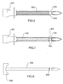
- FIG. 3 and 7 illustrate different exemplary embodiments of patterns of radiopacity that can be adopted in this invention.
- a radiopaque band 300 is located at the edge 204 of the coating and thereby aids in distinguishing between the coated region 103 and uncoated region 104.
- the radiopaque band 300 is located before the coating end-point 204. It may run 360° around the shaft or be applied through a certain distance of the circumference, for example through 180° or 90°.
- Figure 3 illustrates one embodiment that includes a radiopaque band 300 through 180° of the shaft, on the side of the beveled tip, just before the coating end-point 204. This provides a clear demarcation between the coated 103 and exposed regions 104 of the needle 102.
- the band 300 can be applied in a number of ways including techniques such as, but not limited to, vapor deposition, ion implantation, dip coating, metal plating and electro plating. Bands of radiopaque materials such as platinum iridium bands can also be fused onto the needle 102.
- a radiopaque marker 400 may be placed on the needle 102 to distinguish between the coated metal shaft 103 and the exposed metal tip 104 and may be a variety of shapes and sizes. The shape of the marker 400 may also be used to indicate the direction of the beveled tip.
- Figure 5 illustrates another configuration outside the scope of the invention.
- the entire exposed part 104 of the needle 102 is radiopaque indicated at numeral 500 and can be discerned better when viewed under a fluoroscope.
- the coated region of the needle 103 can be masked and the exposed tip 104 coated with a radiopaque material. Techniques such as vapor deposition and ion bombardment can be used to achieve such coating.
- the insulating coating on the needle can be made radiopaque in a number of ways such as vapor deposition, ion-bombardment and ion-implantation. This renders the entire insulated portion of the needle radiopaque.
- Figure 7 illustrates the needle 102 with two radiopaque bands 700 at the coating end-point 204 and the edge of the exposed tip 104. This defines the region of the exposed tip 104 where delivery of high frequency electrical current to the tissue 106 occurs.
- Figure 8 illustrates the stylet 205 with radiopaque marking 800, which may include any of the embodiments described in Figures 3-7 above.
- the stylet 205 and needle 102 are inserted into the patient's body 106 to ensure correct placement.
- the radiopacity on the stylet 205 will serve to identify the exposed tip 104 on the needle 102.
- radiopaque ink with tungsten that is pad printed is radiopaque ink with tungsten that is pad printed. The material is selected based on its radiopacity. Addition of a silver solder band is another technique that may be used to accomplish radiopacity.
- suitable materials include, but are not limited to, high-density metals such as platinum, iridium, golf, silver, tantalum or their alloys, or radiopaque polymeric compounds. Such materials are highly visible under fluoroscopic illumination and are therefore visible even at minimal thickness.
Description
- The invention relates to a needle that delivers electrical current and more particularly to a needle that delivers high frequency electrical current in the vicinity of a neural structure.
- A minimally invasive technique of delivering high frequency electrical current has shown to relieve localized pain in many patients. The high frequency electrical current is typically delivered from a generator via connected electrodes that are placed in a patient's body. The needles include an insulated shaft with an exposed electrically conductive tip. Tissue resistance to the high frequency electrical current at the tip causes heating of adjacent tissue. When temperature increases sufficiently tissue coagulates. The temperature that is sufficient to coagulate unmyelinated nerve structures is 45 °C, at which point a lesion is formed and pain signals are blocked. This results in relief from pain.
- Needles with varying geometries are used in such applications. For example, the exposed tip of the needle can be pointed, blunt and rounded or open, varying in shape in accordance with the needs of different procedures. Pointed tips are self-penetrating while rounded tips are useful in soft tissue areas such as the brain where it is critical not to damage nerves. However, blunt needles can do more tissue damage than small diameter sharp needles. Open tips can be used to deliver a therapeutic agent during electrical treatment. United States Patent No.
6,146,380 to Racz et al. describes electrical needles with curved tips used in high frequency lesioning. - This technique of relieving back pain has also been used with needles penetrating the intervertebral disk. United States Patent Nos.
5,433,739 and5,571,147 to Sluijter et al. and WIPO publicationWO 01/45579 to Finch - For treatment, the needle having a hollow shaft and a removable stylet therein is inserted into the patient's body and positioned. Once the needle is positioned, the stylet is withdrawn and a distal end of a high frequency probe is inserted until the distal end of the probe is at least flush with the distal end of the shaft, (i.e. the exposed tip). The probe is connected to an external signal generator that generates high frequency electrical current.
- These needles are often used to denervate certain portions of a spine of the patient. Accurate placement of the needle in a complicated structure like the spine requires great technical skill by a treating clinician. In these procedures, the needle is viewed via X-ray or a fluoroscope to assist placement and is guided into the body. One limitation of the technique used currently is that the insulated shaft is not distinguishable from the exposed tip of the needle under X-ray or fluoroscopy. Therefore, accurate visualization of the exposed tip is not possible.
- Prior art devices for accurate placement have not been used in conjunction with radio frequency needles. Radiopaque marking has been used to accomplish precise placement of catheters and stents. United States Patent No.
5,429,597 to Demello et al. discloses a balloon catheter having a radiopaque distal tip composed of a polymer mixed with a radiopaque powder such as tungsten. United States Patent No.6,315,790 to Gerberding et al. describes a catheter constructed with radiopaque polymer hubs where the hubs provided the dual function of stent crimping and marker bands. - An example of a catheter utilizing an external marker band is described in United States Patent No.
5,759,174 to Fischell et al. The catheter has a single external metal marker band to identify the central portion of the stenosis once the delivery catheter is removed. - In spite of the improved illumination of the aforementioned devices when marked, there are some limitations to their application. Upon attachment conventional radiopaque markers may project from the surface of the catheter or stent, thereby causing a departure from its ideal profile. Some markers add rigidity to the stent and catheter in areas that had been designated for deformation. A needle for delivering radio frequency that overcomes some or all of the limitations of the prior art is desired.
-
WO 02/054941 WO 02/089686 - In accordance with the present invention, there is provided a needle for insertion into a patient's body for delivering high frequency electrical current as set forth in claim 1.
- The present invention provides for improved placement of a needle delivering high frequency energy by incorporating a radiopaque marker to distinguish the exposed tip from the shaft under fluoroscopic visualization.
- To facilitate precise placement of the exposed tip, the tip is distinguishable from the rest of the needle when viewed under X-rays and fluoroscopy. When a needle with radiopaque marking, according to the present invention, is inserted in the patient's body, the location of a lesion made or to be made by the needle can be easily determined, as the tip of the needle can be distinguished from the electrically insulated shaft.
- The present invention provides a needle for insertion into a patient's body comprising an electrically insulated shaft having an electrically conductive tip portion and a radiopaque marker.
- The tip portion of the needle is the exposed tip and can be of varying dimensions. The radiopaque marker distinguishes the electrically insulated portion of the needle from the tip portion. This effectively identifies the position of the needle when in the body. The marker may be adapted to needles having various geometric shapes. The insulated portion of the needle includes an insulating coating. The coating may cover the radiopaque marker on the needle preventing a departure from the needle's true profile.
- The radiopaque marker is band-shaped and can comprise radiopaque coatings of metals/polymers, or radiopaque materials deposited on the surface of the needle by techniques such as ion implantation or vapor deposition. These features and others will be apparent in the detailed description that follows.
- In order that the invention may be readily understood, embodiments of the invention and arrangements not in accordance with the invention are illustrated by way of examples in the accompanying drawings, in which:
-
Fig. 1 is a schematic illustration of a needle connected to a high frequency generator, in accordance with an embodiment; -
Fig. 2 is a side elevation view of an embodiment of the needle including a stylet; -
Figures 3, 4, 5 ,6 and 7 illustrate side elevation views of different configurations of a needle with radiopaque marking, whereinFigures 3 and7 illustrate embodiments of a needle with radiopaque marking and -
Figures 4, 5 and6 illustrate alternative needles outside the scope of the present invention; -
Figures 8 ,9A and 9B illustrate modification to a stylet to impart radiopacity. - In accordance with an aspect of the invention a medical apparatus is provided for delivering high frequency electrical current to neural structures. As illustrated in
Figure 1 , the medical apparatus comprises agenerator 100 for producing high frequency electrical current, aneedle 102 with anelectrical probe 110 connected to thegenerator 100 that is placed in theneedle 102 for delivering the high frequency electrical current and areference electrode 101 that completes the circuit. Theneedle 102 with theprobe 110 is placed in a portion of a patient's body indicated generally at 106. - As can be seen more clearly in
Figure 2 , the hollow shaft of theneedle 102 is covered with aninsulating coating 103 leaving a portion of thetip 104 uncoated, exposed and electrically conductive. Thetip 104 may have a sharpened end that will assist with penetration of thetip 104 into the tissue of thebody 106 during percutaneous entry. The exposedtip 104 represents the active electrode area. Thereference electrode 101 typically has a much larger area than the exposedtip 104 so that there is no heating at the surface of thebody 106 where thereference electrode 101 is attached. The passage of high frequency electrical current through theneedle 102 produces alesion 105 in the region of the exposedtip 104. Thelesion 105 causes coagulation of the neural structures in that region and is responsible for pain relief. It is therefore important to know the position of the exposedtip 104 to gauge the relative position and region that will be affected by the high frequency electrical current. - As stated above,
Figure 2 depicts theneedle 102 having a hollow shaft typically of one or more metals and ahub 201. Preferably thehub 201 is a Luer lock type molded to the shaft; however, other methods of attachment may be used as will be understood by a person skilled in the art. Inserted inneedle 102 through the hollow shaft is anelongate stylet 205 shown in dotted outline. Thestylet 205 is adapted to assist in piercing the skin and tissue for entry to a treatment area. Thestylet 205 comprises acap 200 cooperating withLuer lock hub 201. Thehub 201 is also operable to accommodate anelectrical probe 110 that is inserted into the shaft of theneedle 102 when thestylet 205 is removed. A portion of the shaft is covered with an electrically insulatingcoating 103 leaving thetip 104 exposed. The end-point of the insulatingcoating 103 on theneedle 102 is indicated atnumeral 204. In use, theneedle 102 with thestylet 205 is inserted into thebody 106. Once a correct position has been attained thestylet 205 is removed and theelectrical probe 110 that delivers the high frequency electrical current is inserted through theneedle 102. - The
needle 102 with thestylet 205 is inserted into the patient'sbody 106 under X-ray/fluoroscopic guidance. One common method for inserting theneedle 102 is to locate an X-ray source along one or more desired axes. An image detector on the opposite side of thebody portion 106 where theneedle 102 is inserted receives the X-rays, thereby permitting verification of the proper location and orientation of thetip 104. Radiopaque marking on theneedle 102 orstylet 205 will not only enable its better visualization in this process, but will also indicate theprecise location 204 of the end-point of the insulatingcoating 103 on theneedle 102. When the radiopaque marking is onneedle 102, the verification oflocation 204 can be performed along with the verification of the location and orientation oftip 104 by removing thestylet 205 and taking a X-ray/fluoroscopic picture. With reference toFigs. 9A and 9B , radiopaque marking on thestylet 205 may be enhanced by reducing a mass of thestylet 205 at alocation 900 of thestylet 205 where theradiopaque band 901 is to be applied. The mass may be reduced by removing material from thestylet 205 such as by grinding or other means. Alternatively thestylet 205 may be originally formed with a reduced mass about thelocation 900. Radiopaque marking on thestylet 205 may be coupled with grinding of thestylet 205 mass to increase the thickness of the radiopaque band. Alternatively, theneedle 102 with thestylet 205 having reduced mass atlocation 900 could be used to impart radiopacity without any additional band. Thestylet 205 could also be made of materials of lower radiopacity than theneedle 102 to impart greater illumination. - A radiopaque marker could be applied on selected portions of the
needle 102 by, for example, use of masks. - Advantageously selected patterns of radiopacity will allow the precise orientation to be discerned by inspection of the fluoroscopic image.
Figures 3 and7 illustrate different exemplary embodiments of patterns of radiopacity that can be adopted in this invention. - In accordance with the invention, as in the embodiment illustrated in
Figure 3 , aradiopaque band 300 is located at theedge 204 of the coating and thereby aids in distinguishing between thecoated region 103 anduncoated region 104. Theradiopaque band 300 is located before the coating end-point 204. It may run 360° around the shaft or be applied through a certain distance of the circumference, for example through 180° or 90°.Figure 3 illustrates one embodiment that includes aradiopaque band 300 through 180° of the shaft, on the side of the beveled tip, just before the coating end-point 204. This provides a clear demarcation between the coated 103 and exposedregions 104 of theneedle 102. - The
band 300 can be applied in a number of ways including techniques such as, but not limited to, vapor deposition, ion implantation, dip coating, metal plating and electro plating. Bands of radiopaque materials such as platinum iridium bands can also be fused onto theneedle 102. - An alternate configuration outside the scope of the invention is depicted in
Figure 4 . Aradiopaque marker 400 may be placed on theneedle 102 to distinguish between thecoated metal shaft 103 and the exposedmetal tip 104 and may be a variety of shapes and sizes. The shape of themarker 400 may also be used to indicate the direction of the beveled tip. -
Figure 5 illustrates another configuration outside the scope of the invention. The entireexposed part 104 of theneedle 102, is radiopaque indicated atnumeral 500 and can be discerned better when viewed under a fluoroscope. The coated region of theneedle 103 can be masked and the exposedtip 104 coated with a radiopaque material. Techniques such as vapor deposition and ion bombardment can be used to achieve such coating. - An alternate configuration which is, per se, outside the scope of the present invention, can be obtained by imparting radiopacity to the insulating
coating 600 as illustrated inFigure 6 . The insulating coating on the needle can be made radiopaque in a number of ways such as vapor deposition, ion-bombardment and ion-implantation. This renders the entire insulated portion of the needle radiopaque. -
Figure 7 illustrates theneedle 102 with tworadiopaque bands 700 at the coating end-point 204 and the edge of the exposedtip 104. This defines the region of the exposedtip 104 where delivery of high frequency electrical current to thetissue 106 occurs. -
Figure 8 illustrates thestylet 205 withradiopaque marking 800, which may include any of the embodiments described inFigures 3-7 above. Thestylet 205 andneedle 102 are inserted into the patient'sbody 106 to ensure correct placement. The radiopacity on thestylet 205 will serve to identify the exposedtip 104 on theneedle 102. - An example of suitable material that may be used to impart the desired radiopacity is radiopaque ink with tungsten that is pad printed. The material is selected based on its radiopacity. Addition of a silver solder band is another technique that may be used to accomplish radiopacity. Other suitable materials include, but are not limited to, high-density metals such as platinum, iridium, golf, silver, tantalum or their alloys, or radiopaque polymeric compounds. Such materials are highly visible under fluoroscopic illumination and are therefore visible even at minimal thickness.
- The embodiments of the invention described above are intended to be exemplary only. The scope of the invention is therefore intended to be limited solely by the scope of the appended claims.
Claims (6)
- A needle (102) for insertion into a patient's body for delivering high frequency electrical current comprising:an electrically insulated shaft having an electrically insulated portion and an exposed electrically conductive tip portion (104), wherein said insulated portion comprises an insulating coating (103); anda band-shaped radiopaque marker (300);characterised in that said marker (300) is located at an edge (204) of the coating, to distinguish between the exposed tip portion of the needle (104) and the electrically insulated portion (103) of the needle under fluoroscopic visualization.
- The needle of claim 1, wherein said insulating coating (103) covers the radiopaque marker (300).
- The needle of claim 1, wherein the shaft is hollow.
- The needle of any preceding claim, wherein the needle is operable to connect to an energy source.
- An apparatus comprising:the needle of claim 1, wherein the shaft is hollow, the apparatus further comprising:a stylet (205) operable to be located within the shaft during insertion of said shaft into said patient's body and operable to be removed therefrom after insertion.
- The apparatus of claim 5, further comprising a probe (110), operable to be connected to an energy source, and operable to be located within said shaft for delivery of high frequency electrical current.
Applications Claiming Priority (3)
| Application Number | Priority Date | Filing Date | Title |
|---|---|---|---|
| US10/382,836 US20040176759A1 (en) | 2003-03-07 | 2003-03-07 | Radiopaque electrical needle |
| US382836 | 2003-03-07 | ||
| PCT/CA2004/000338 WO2004078052A1 (en) | 2003-03-07 | 2004-03-05 | Electrical needle with radiopaque marker |
Publications (2)
| Publication Number | Publication Date |
|---|---|
| EP1603473A1 EP1603473A1 (en) | 2005-12-14 |
| EP1603473B1 true EP1603473B1 (en) | 2016-03-02 |
Family
ID=32926976
Family Applications (1)
| Application Number | Title | Priority Date | Filing Date |
|---|---|---|---|
| EP04717535.1A Expired - Lifetime EP1603473B1 (en) | 2003-03-07 | 2004-03-05 | Electrical needle with radiopaque marker |
Country Status (4)
| Country | Link |
|---|---|
| US (2) | US20040176759A1 (en) |
| EP (1) | EP1603473B1 (en) |
| AU (2) | AU2004216926A1 (en) |
| WO (1) | WO2004078052A1 (en) |
Families Citing this family (60)
| Publication number | Priority date | Publication date | Assignee | Title |
|---|---|---|---|---|
| US7811282B2 (en) | 2000-03-06 | 2010-10-12 | Salient Surgical Technologies, Inc. | Fluid-assisted electrosurgical devices, electrosurgical unit with pump and methods of use thereof |
| US6689131B2 (en) | 2001-03-08 | 2004-02-10 | Tissuelink Medical, Inc. | Electrosurgical device having a tissue reduction sensor |
| US8048070B2 (en) | 2000-03-06 | 2011-11-01 | Salient Surgical Technologies, Inc. | Fluid-assisted medical devices, systems and methods |
| ES2643763T3 (en) | 2000-03-06 | 2017-11-24 | Salient Surgical Technologies, Inc. | Fluid supply system and controller for electrosurgical devices |
| US6558385B1 (en) | 2000-09-22 | 2003-05-06 | Tissuelink Medical, Inc. | Fluid-assisted medical device |
| US8043287B2 (en) | 2002-03-05 | 2011-10-25 | Kimberly-Clark Inc. | Method of treating biological tissue |
| US20050277918A1 (en) * | 2003-03-07 | 2005-12-15 | Baylis Medical Company Inc. | Electrosurgical cannula |
| US8518036B2 (en) | 2002-03-05 | 2013-08-27 | Kimberly-Clark Inc. | Electrosurgical tissue treatment method |
| US8882755B2 (en) | 2002-03-05 | 2014-11-11 | Kimberly-Clark Inc. | Electrosurgical device for treatment of tissue |
| US6896675B2 (en) | 2002-03-05 | 2005-05-24 | Baylis Medical Company Inc. | Intradiscal lesioning device |
| US6907884B2 (en) | 2002-09-30 | 2005-06-21 | Depay Acromed, Inc. | Method of straddling an intraosseous nerve |
| US7258690B2 (en) | 2003-03-28 | 2007-08-21 | Relievant Medsystems, Inc. | Windowed thermal ablation probe |
| US8361067B2 (en) | 2002-09-30 | 2013-01-29 | Relievant Medsystems, Inc. | Methods of therapeutically heating a vertebral body to treat back pain |
| EP1572020A4 (en) | 2002-10-29 | 2006-05-03 | Tissuelink Medical Inc | Fluid-assisted electrosurgical scissors and methods |
| US7727232B1 (en) | 2004-02-04 | 2010-06-01 | Salient Surgical Technologies, Inc. | Fluid-assisted medical devices and methods |
| US8187268B2 (en) | 2004-05-26 | 2012-05-29 | Kimberly-Clark, Inc. | Electrosurgical apparatus having a temperature sensor |
| US20060259008A1 (en) * | 2005-04-27 | 2006-11-16 | Allergan, Inc. | Apparatus and methods useful for intravitreal injection of drugs |
| DE202006021213U1 (en) | 2005-07-21 | 2013-11-08 | Covidien Lp | Apparatus for treating a hollow anatomical structure |
| US7763034B2 (en) * | 2006-01-24 | 2010-07-27 | Medtronic, Inc. | Transobturator lead implantation for pelvic floor stimulation |
| US8374673B2 (en) | 2007-01-25 | 2013-02-12 | Warsaw Orthopedic, Inc. | Integrated surgical navigational and neuromonitoring system having automated surgical assistance and control |
| US7987001B2 (en) | 2007-01-25 | 2011-07-26 | Warsaw Orthopedic, Inc. | Surgical navigational and neuromonitoring instrument |
| US8954162B2 (en) * | 2007-04-25 | 2015-02-10 | Medtronic, Inc. | Medical device implantation |
| US9402643B2 (en) | 2008-01-15 | 2016-08-02 | Novartis Ag | Targeted illumination for surgical instrument |
| US10278725B2 (en) | 2008-09-15 | 2019-05-07 | Paul M. Zeltzer | Lumbar puncture detection device |
| US10028753B2 (en) | 2008-09-26 | 2018-07-24 | Relievant Medsystems, Inc. | Spine treatment kits |
| EP3406210A1 (en) | 2008-09-26 | 2018-11-28 | Relievant Medsystems, Inc. | Systems and for navigating an instrument through bone |
| US20100137908A1 (en) * | 2008-12-01 | 2010-06-03 | Zimmer Spine, Inc. | Dynamic Stabilization System Components Including Readily Visualized Polymeric Compositions |
| BRPI0924552A2 (en) * | 2009-06-09 | 2019-08-27 | Korea Univ Industrial & Academic Collaboration Foundation | controllable steering electrode body to selectively remove body tissue, and guide tubing |
| CA2778997C (en) | 2009-11-05 | 2022-03-08 | Nimbus Concepts, Llc | Methods and systems for radio frequency neurotomy |
| MX2012013280A (en) | 2010-05-21 | 2013-03-05 | Nimbus Concepts Llc | Systems and methods for tissue ablation. |
| US9402560B2 (en) | 2010-07-21 | 2016-08-02 | Diros Technology Inc. | Advanced multi-purpose catheter probes for diagnostic and therapeutic procedures |
| BR112013008190A2 (en) * | 2010-10-04 | 2017-12-12 | Nervomatrix Ltd | electrode and apparatus |
| US10765473B2 (en) | 2010-11-08 | 2020-09-08 | Baylis Medical Company Inc. | Electrosurgical device having a lumen |
| US20120245486A1 (en) * | 2011-03-25 | 2012-09-27 | Anthony Melchiorri | Ghost-core biopsy needle |
| US8939969B2 (en) | 2011-09-30 | 2015-01-27 | Kimberly-Clark, Inc. | Electrosurgical device with offset conductive element |
| AU2012362524B2 (en) | 2011-12-30 | 2018-12-13 | Relievant Medsystems, Inc. | Systems and methods for treating back pain |
| US10588691B2 (en) | 2012-09-12 | 2020-03-17 | Relievant Medsystems, Inc. | Radiofrequency ablation of tissue within a vertebral body |
| CA2881740A1 (en) * | 2012-11-01 | 2014-05-08 | Alcon Research Ltd. | Illuminated vitrectomy cutter with adjustable illumination aperture |
| WO2014071161A1 (en) | 2012-11-05 | 2014-05-08 | Relievant Medsystems, Inc. | System and methods for creating curved paths through bone and modulating nerves within the bone |
| US10076384B2 (en) | 2013-03-08 | 2018-09-18 | Symple Surgical, Inc. | Balloon catheter apparatus with microwave emitter |
| US11937873B2 (en) | 2013-03-12 | 2024-03-26 | Boston Scientific Medical Device Limited | Electrosurgical device having a lumen |
| AU2014290582B2 (en) | 2013-07-14 | 2017-08-31 | Cardiac Pacemakers, Inc. | Multi-electrode lead with backing for mecho/baroreceptor stimulation |
| US9724151B2 (en) | 2013-08-08 | 2017-08-08 | Relievant Medsystems, Inc. | Modulating nerves within bone using bone fasteners |
| US9839785B2 (en) | 2013-12-13 | 2017-12-12 | Cardiac Pacemakers, Inc. | Surgical instrument for implanting leads for baroreceptor stimulation therapy |
| US10029091B2 (en) | 2014-02-20 | 2018-07-24 | Cardiac Pacemakers, Inc. | Apparatus for baroreceptor stimulation therapy |
| US20170049503A1 (en) * | 2014-05-15 | 2017-02-23 | Cosman Medical, Inc. | Electrosurgical system |
| US20150366467A1 (en) * | 2014-06-19 | 2015-12-24 | Cardiac Pacemakers, Inc. | Baroreceptor mapping system |
| US9572975B2 (en) | 2014-09-02 | 2017-02-21 | Cardiac Pacemakers, Inc. | Paddle leads configured for suture fixation |
| US9616219B2 (en) | 2014-09-16 | 2017-04-11 | Cardiac Pacemakers, Inc. | Paddle leads having asymmetric electrode configurations |
| US11173008B2 (en) * | 2015-11-01 | 2021-11-16 | Alcon Inc. | Illuminated ophthalmic cannula |
| US9956053B2 (en) | 2016-03-04 | 2018-05-01 | Novartis Ag | Cannula with an integrated illumination feature |
| KR20190062419A (en) | 2016-10-04 | 2019-06-05 | 아벤트, 인크. | The cooled RF probe |
| US11439742B2 (en) * | 2017-02-08 | 2022-09-13 | Veran Medical Technologies, Inc. | Localization needle |
| GB2571753A (en) * | 2018-03-07 | 2019-09-11 | The Francis Crick Institute Ltd | Multimodal needle |
| US11478297B2 (en) | 2018-03-23 | 2022-10-25 | Avent, Inc. | System and method for controlling energy delivered to an area of tissue during a treatment procedure |
| USD885560S1 (en) | 2018-12-14 | 2020-05-26 | Avent, Inc. | Introducer hub with fluid delivery port |
| US20200188684A1 (en) * | 2018-12-14 | 2020-06-18 | Avent, Inc. | Polymer Introducer for Use with an RF Ablation Probe and Associated RF Ablation Probe Assembly |
| WO2020227540A1 (en) * | 2019-05-08 | 2020-11-12 | Atricure, Inc. | Biological tissue position location and marking |
| JP7284649B2 (en) * | 2019-06-21 | 2023-05-31 | 株式会社メディカロイド | electrosurgical instruments and covers |
| AU2020346827A1 (en) | 2019-09-12 | 2022-03-31 | Relievant Medsystems, Inc. | Systems and methods for tissue modulation |
Citations (2)
| Publication number | Priority date | Publication date | Assignee | Title |
|---|---|---|---|---|
| WO2002054941A2 (en) * | 2001-01-11 | 2002-07-18 | Rita Medical Systems Inc | Bone-treatment instrument and method |
| WO2002089686A1 (en) * | 2001-05-10 | 2002-11-14 | Rita Medical Systems, Inc. | Rf tissue ablation apparatus and method |
Family Cites Families (61)
| Publication number | Priority date | Publication date | Assignee | Title |
|---|---|---|---|---|
| US4041931A (en) * | 1976-05-17 | 1977-08-16 | Elliott Donald P | Radiopaque anastomosis marker |
| US4202349A (en) * | 1978-04-24 | 1980-05-13 | Jones James W | Radiopaque vessel markers |
| US4257429A (en) * | 1979-02-07 | 1981-03-24 | Medtronic, Inc. | Stylet retainer and extension |
| DE2910749C2 (en) * | 1979-03-19 | 1982-11-25 | Dr. Eduard Fresenius, Chemisch-pharmazeutische Industrie KG, 6380 Bad Homburg | Catheter with contrast stripes |
| US4657024A (en) * | 1980-02-04 | 1987-04-14 | Teleflex Incorporated | Medical-surgical catheter |
| US4419095A (en) | 1980-05-14 | 1983-12-06 | Shiley, Inc. | Cannula with radiopaque tip |
| US5693043A (en) * | 1985-03-22 | 1997-12-02 | Massachusetts Institute Of Technology | Catheter for laser angiosurgery |
| US5209749A (en) * | 1990-05-11 | 1993-05-11 | Applied Urology Inc. | Fluoroscopically alignable cutter assembly and method of using the same |
| US5586982A (en) * | 1992-04-10 | 1996-12-24 | Abela; George S. | Cell transfection apparatus and method |
| FR2691905B1 (en) * | 1992-06-03 | 1998-10-16 | Jacques Brehier | EXTRACTIBLE CARDIAC PROBE AND METHOD FOR IMPLEMENTING SAME. |
| US5571147A (en) * | 1993-11-02 | 1996-11-05 | Sluijter; Menno E. | Thermal denervation of an intervertebral disc for relief of back pain |
| US5433739A (en) * | 1993-11-02 | 1995-07-18 | Sluijter; Menno E. | Method and apparatus for heating an intervertebral disc for relief of back pain |
| US5429617A (en) * | 1993-12-13 | 1995-07-04 | The Spectranetics Corporation | Radiopaque tip marker for alignment of a catheter within a body |
| US5429597A (en) * | 1994-03-01 | 1995-07-04 | Boston Scientific Corporation | Kink resistant balloon catheter and method for use |
| US5415664A (en) * | 1994-03-30 | 1995-05-16 | Corvita Corporation | Method and apparatus for introducing a stent or a stent-graft |
| US6251104B1 (en) * | 1995-05-10 | 2001-06-26 | Eclipse Surgical Technologies, Inc. | Guiding catheter system for ablating heart tissue |
| DE19541566A1 (en) * | 1995-11-08 | 1997-05-15 | Laser & Med Tech Gmbh | Application system for HF surgery for interstitial thermotherapy in bipolar technology (HF-ITT) |
| US5779642A (en) * | 1996-01-16 | 1998-07-14 | Nightengale; Christopher | Interrogation device and method |
| US7189222B2 (en) * | 1996-04-30 | 2007-03-13 | Medtronic, Inc. | Therapeutic method of treatment of alzheimer's disease |
| US6048331A (en) * | 1996-05-14 | 2000-04-11 | Embol-X, Inc. | Cardioplegia occluder |
| US5800428A (en) * | 1996-05-16 | 1998-09-01 | Angeion Corporation | Linear catheter ablation system |
| US5855577A (en) * | 1996-09-17 | 1999-01-05 | Eclipse Surgical Technologies, Inc. | Bow shaped catheter |
| US6148380A (en) * | 1997-01-02 | 2000-11-14 | Intel Corporation | Method and apparatus for controlling data transfer between a synchronous DRAM-type memory and a system bus |
| US5759174A (en) * | 1997-01-29 | 1998-06-02 | Cathco, Inc. | Angioplasty balloon with an expandable external radiopaque marker band |
| US5885227A (en) * | 1997-03-25 | 1999-03-23 | Radius Medical Technologies, Inc. | Flexible guidewire with radiopaque plastic tip |
| US5876373A (en) * | 1997-04-04 | 1999-03-02 | Eclipse Surgical Technologies, Inc. | Steerable catheter |
| US6056743A (en) * | 1997-11-04 | 2000-05-02 | Scimed Life Systems, Inc. | Percutaneous myocardial revascularization device and method |
| US6217527B1 (en) * | 1998-09-30 | 2001-04-17 | Lumend, Inc. | Methods and apparatus for crossing vascular occlusions |
| US6146380A (en) | 1998-01-09 | 2000-11-14 | Radionics, Inc. | Bent tip electrical surgical probe |
| US6231546B1 (en) * | 1998-01-13 | 2001-05-15 | Lumend, Inc. | Methods and apparatus for crossing total occlusions in blood vessels |
| US6471700B1 (en) * | 1998-04-08 | 2002-10-29 | Senorx, Inc. | Apparatus and method for accessing biopsy site |
| US6758848B2 (en) * | 1998-03-03 | 2004-07-06 | Senorx, Inc. | Apparatus and method for accessing a body site |
| US6796976B1 (en) * | 1998-03-06 | 2004-09-28 | Scimed Life Systems, Inc. | Establishing access to the body |
| US6196967B1 (en) * | 1998-03-18 | 2001-03-06 | Linvatec Corporation | Arthroscopic component joining system |
| WO1999048548A1 (en) | 1998-03-23 | 1999-09-30 | Medtronic, Inc. | Catheter having extruded radiopaque stripes embedded in soft tip and method of fabrication |
| US6149380A (en) * | 1999-02-04 | 2000-11-21 | Pratt & Whitney Canada Corp. | Hardwall fan case with structured bumper |
| US6464723B1 (en) * | 1999-04-22 | 2002-10-15 | Advanced Cardiovascular Systems, Inc. | Radiopaque stents |
| US6315790B1 (en) * | 1999-06-07 | 2001-11-13 | Scimed Life Systems, Inc. | Radiopaque marker bands |
| US6478793B1 (en) * | 1999-06-11 | 2002-11-12 | Sherwood Services Ag | Ablation treatment of bone metastases |
| US6306132B1 (en) * | 1999-06-17 | 2001-10-23 | Vivant Medical | Modular biopsy and microwave ablation needle delivery apparatus adapted to in situ assembly and method of use |
| TW415136B (en) * | 1999-07-22 | 2000-12-11 | Hon Hai Prec Ind Co Ltd | Method of producing electric connector terminal and electric connector product thereof |
| DE60045386D1 (en) | 1999-12-21 | 2011-01-27 | Covidien Ag | DEVICE FOR THE THERMAL TREATMENT OF BELTS |
| WO2001054761A2 (en) * | 2000-01-28 | 2001-08-02 | William Cook, Europe Aps | Endovascular medical device with plurality of wires |
| US6770070B1 (en) | 2000-03-17 | 2004-08-03 | Rita Medical Systems, Inc. | Lung treatment apparatus and method |
| US6308132B1 (en) * | 2000-06-13 | 2001-10-23 | Honeywell International Inc. | Method and apparatus for displaying real time navigational information |
| US6773446B1 (en) * | 2000-08-02 | 2004-08-10 | Cordis Corporation | Delivery apparatus for a self-expanding stent |
| US6893421B1 (en) * | 2000-08-08 | 2005-05-17 | Scimed Life Systems, Inc. | Catheter shaft assembly |
| US20030158545A1 (en) * | 2000-09-28 | 2003-08-21 | Arthrocare Corporation | Methods and apparatus for treating back pain |
| US6501992B1 (en) * | 2000-10-17 | 2002-12-31 | Medtronic, Inc. | Radiopaque marking of lead electrode zone in a continuous conductor construction |
| US7422586B2 (en) * | 2001-02-28 | 2008-09-09 | Angiodynamics, Inc. | Tissue surface treatment apparatus and method |
| EP1418972A1 (en) * | 2001-05-01 | 2004-05-19 | C.R. Bard, Inc. | Method and apparatus for altering conduction properties along pathways in the heart and in vessels in conductive communication with the heart |
| US20020193781A1 (en) * | 2001-06-14 | 2002-12-19 | Loeb Marvin P. | Devices for interstitial delivery of thermal energy into tissue and methods of use thereof |
| DE10129912A1 (en) * | 2001-06-21 | 2003-01-02 | Efmt Entwicklungs Und Forschun | needle electrode |
| US20030032936A1 (en) * | 2001-08-10 | 2003-02-13 | Lederman Robert J. | Side-exit catheter and method for its use |
| US20030093007A1 (en) * | 2001-10-17 | 2003-05-15 | The Government Of The U.S.A., As Represented By The Secretary, Department Of Health And Human Serv | Biopsy apparatus with radio frequency cauterization and methods for its use |
| AU2002364514B2 (en) * | 2001-11-29 | 2008-12-18 | Cook Medical Technologies Llc | Medical device delivery system |
| WO2003105668A2 (en) * | 2002-06-01 | 2003-12-24 | Alfred E. Mann Institute For Biomedical Engineering At The University Of Southern California | Injection devices and methods for testing implants and for unimpeded target location testing |
| US20040106891A1 (en) * | 2002-08-30 | 2004-06-03 | Inrad, Inc. | Localizing needle with fluid delivery |
| US6902526B2 (en) * | 2002-10-23 | 2005-06-07 | Orthopaedic Development, Llc | Visualizing ablation device and procedure |
| US7399296B2 (en) * | 2003-02-26 | 2008-07-15 | Medtronic Vascular, Inc. | Catheter having highly radiopaque embedded segment |
| US20040267203A1 (en) * | 2003-06-26 | 2004-12-30 | Potter Daniel J. | Splittable cannula having radiopaque marker |
-
2003
- 2003-03-07 US US10/382,836 patent/US20040176759A1/en not_active Abandoned
-
2004
- 2004-03-05 WO PCT/CA2004/000338 patent/WO2004078052A1/en active Application Filing
- 2004-03-05 EP EP04717535.1A patent/EP1603473B1/en not_active Expired - Lifetime
- 2004-03-05 AU AU2004216926A patent/AU2004216926A1/en not_active Abandoned
-
2005
- 2005-03-15 US US11/079,318 patent/US7593778B2/en not_active Expired - Lifetime
-
2010
- 2010-07-12 AU AU2010202944A patent/AU2010202944B2/en not_active Expired
Patent Citations (2)
| Publication number | Priority date | Publication date | Assignee | Title |
|---|---|---|---|---|
| WO2002054941A2 (en) * | 2001-01-11 | 2002-07-18 | Rita Medical Systems Inc | Bone-treatment instrument and method |
| WO2002089686A1 (en) * | 2001-05-10 | 2002-11-14 | Rita Medical Systems, Inc. | Rf tissue ablation apparatus and method |
Also Published As
| Publication number | Publication date |
|---|---|
| WO2004078052A1 (en) | 2004-09-16 |
| US7593778B2 (en) | 2009-09-22 |
| EP1603473A1 (en) | 2005-12-14 |
| AU2010202944B2 (en) | 2012-06-28 |
| AU2010202944A1 (en) | 2010-07-29 |
| US20050159797A1 (en) | 2005-07-21 |
| AU2004216926A1 (en) | 2004-09-16 |
| US20040176759A1 (en) | 2004-09-09 |
Similar Documents
| Publication | Publication Date | Title |
|---|---|---|
| EP1603473B1 (en) | Electrical needle with radiopaque marker | |
| US11135424B2 (en) | Apparatus, system, and method for targeted placement of a percutaneous electrode | |
| US8571685B2 (en) | Directional stimulation lead and orientation system | |
| EP3413962B1 (en) | Stimulation needle apparatus | |
| US20100185082A1 (en) | Device and method for electrosurgery | |
| EP1863558B1 (en) | Electrosurgical cannula | |
| US9216053B2 (en) | Elongate member providing a variation in radiopacity | |
| US8463401B2 (en) | Apparatus for implanting an electrical stimulation lead | |
| AU2010314930C1 (en) | Methods and systems for spinal radio frequency neurotomy | |
| US8801728B2 (en) | Introduction of medical lead into patient | |
| JP3465065B2 (en) | Lead | |
| AU2012315409B2 (en) | Electrosurgical device with offset conductive element | |
| US9314616B2 (en) | Temporary implantable medical electrical leads | |
| US20050256541A1 (en) | Catheter with temporary stimulation electrode | |
| CN114616027A (en) | Fixation component for a multi-electrode implantable medical device | |
| KR20130094729A (en) | Systems and methods for tissue ablation | |
| CN116801939A (en) | Fixation member for multi-electrode implantable medical device | |
| US20230181236A1 (en) | System of medical devices and method for pericardial puncture | |
| AU2023229551A1 (en) | Methods and systems for radiofrequency neurotomy | |
| AU2015261694C1 (en) | Methods and systems for spinal radio frequency neurotomy |
Legal Events
| Date | Code | Title | Description |
|---|---|---|---|
| PUAI | Public reference made under article 153(3) epc to a published international application that has entered the european phase |
Free format text: ORIGINAL CODE: 0009012 |
|
| 17P | Request for examination filed |
Effective date: 20051006 |
|
| AK | Designated contracting states |
Kind code of ref document: A1 Designated state(s): AT BE BG CH CY CZ DE DK EE ES FI FR GB GR HU IE IT LI LU MC NL PL PT RO SE SI SK TR |
|
| AX | Request for extension of the european patent |
Extension state: AL LT LV MK |
|
| DAX | Request for extension of the european patent (deleted) | ||
| 17Q | First examination report despatched |
Effective date: 20100830 |
|
| RAP1 | Party data changed (applicant data changed or rights of an application transferred) |
Owner name: KIMBERLY-CLARK INC. |
|
| RAP1 | Party data changed (applicant data changed or rights of an application transferred) |
Owner name: AVENT, INC. |
|
| GRAP | Despatch of communication of intention to grant a patent |
Free format text: ORIGINAL CODE: EPIDOSNIGR1 |
|
| INTG | Intention to grant announced |
Effective date: 20150706 |
|
| GRAS | Grant fee paid |
Free format text: ORIGINAL CODE: EPIDOSNIGR3 |
|
| GRAA | (expected) grant |
Free format text: ORIGINAL CODE: 0009210 |
|
| AK | Designated contracting states |
Kind code of ref document: B1 Designated state(s): AT BE BG CH CY CZ DE DK EE ES FI FR GB GR HU IE IT LI LU MC NL PL PT RO SE SI SK TR |
|
| INTG | Intention to grant announced |
Effective date: 20160122 |
|
| REG | Reference to a national code |
Ref country code: GB Ref legal event code: FG4D |
|
| REG | Reference to a national code |
Ref country code: AT Ref legal event code: REF Ref document number: 777430 Country of ref document: AT Kind code of ref document: T Effective date: 20160315 Ref country code: CH Ref legal event code: EP |
|
| REG | Reference to a national code |
Ref country code: IE Ref legal event code: FG4D |
|
| REG | Reference to a national code |
Ref country code: DE Ref legal event code: R096 Ref document number: 602004048708 Country of ref document: DE |
|
| REG | Reference to a national code |
Ref country code: FR Ref legal event code: PLFP Year of fee payment: 13 |
|
| REG | Reference to a national code |
Ref country code: NL Ref legal event code: FP |
|
| REG | Reference to a national code |
Ref country code: AT Ref legal event code: MK05 Ref document number: 777430 Country of ref document: AT Kind code of ref document: T Effective date: 20160302 |
|
| PG25 | Lapsed in a contracting state [announced via postgrant information from national office to epo] |
Ref country code: GR Free format text: LAPSE BECAUSE OF FAILURE TO SUBMIT A TRANSLATION OF THE DESCRIPTION OR TO PAY THE FEE WITHIN THE PRESCRIBED TIME-LIMIT Effective date: 20160603 Ref country code: ES Free format text: LAPSE BECAUSE OF FAILURE TO SUBMIT A TRANSLATION OF THE DESCRIPTION OR TO PAY THE FEE WITHIN THE PRESCRIBED TIME-LIMIT Effective date: 20160302 Ref country code: FI Free format text: LAPSE BECAUSE OF FAILURE TO SUBMIT A TRANSLATION OF THE DESCRIPTION OR TO PAY THE FEE WITHIN THE PRESCRIBED TIME-LIMIT Effective date: 20160302 |
|
| PG25 | Lapsed in a contracting state [announced via postgrant information from national office to epo] |
Ref country code: SE Free format text: LAPSE BECAUSE OF FAILURE TO SUBMIT A TRANSLATION OF THE DESCRIPTION OR TO PAY THE FEE WITHIN THE PRESCRIBED TIME-LIMIT Effective date: 20160302 Ref country code: BE Free format text: LAPSE BECAUSE OF NON-PAYMENT OF DUE FEES Effective date: 20160331 Ref country code: AT Free format text: LAPSE BECAUSE OF FAILURE TO SUBMIT A TRANSLATION OF THE DESCRIPTION OR TO PAY THE FEE WITHIN THE PRESCRIBED TIME-LIMIT Effective date: 20160302 Ref country code: PL Free format text: LAPSE BECAUSE OF FAILURE TO SUBMIT A TRANSLATION OF THE DESCRIPTION OR TO PAY THE FEE WITHIN THE PRESCRIBED TIME-LIMIT Effective date: 20160302 |
|
| PG25 | Lapsed in a contracting state [announced via postgrant information from national office to epo] |
Ref country code: EE Free format text: LAPSE BECAUSE OF FAILURE TO SUBMIT A TRANSLATION OF THE DESCRIPTION OR TO PAY THE FEE WITHIN THE PRESCRIBED TIME-LIMIT Effective date: 20160302 |
|
| REG | Reference to a national code |
Ref country code: CH Ref legal event code: PL |
|
| PG25 | Lapsed in a contracting state [announced via postgrant information from national office to epo] |
Ref country code: CZ Free format text: LAPSE BECAUSE OF FAILURE TO SUBMIT A TRANSLATION OF THE DESCRIPTION OR TO PAY THE FEE WITHIN THE PRESCRIBED TIME-LIMIT Effective date: 20160302 Ref country code: RO Free format text: LAPSE BECAUSE OF FAILURE TO SUBMIT A TRANSLATION OF THE DESCRIPTION OR TO PAY THE FEE WITHIN THE PRESCRIBED TIME-LIMIT Effective date: 20160302 Ref country code: PT Free format text: LAPSE BECAUSE OF FAILURE TO SUBMIT A TRANSLATION OF THE DESCRIPTION OR TO PAY THE FEE WITHIN THE PRESCRIBED TIME-LIMIT Effective date: 20160704 Ref country code: SK Free format text: LAPSE BECAUSE OF FAILURE TO SUBMIT A TRANSLATION OF THE DESCRIPTION OR TO PAY THE FEE WITHIN THE PRESCRIBED TIME-LIMIT Effective date: 20160302 |
|
| REG | Reference to a national code |
Ref country code: DE Ref legal event code: R097 Ref document number: 602004048708 Country of ref document: DE |
|
| REG | Reference to a national code |
Ref country code: IE Ref legal event code: MM4A |
|
| PG25 | Lapsed in a contracting state [announced via postgrant information from national office to epo] |
Ref country code: BE Free format text: LAPSE BECAUSE OF FAILURE TO SUBMIT A TRANSLATION OF THE DESCRIPTION OR TO PAY THE FEE WITHIN THE PRESCRIBED TIME-LIMIT Effective date: 20160302 |
|
| PLBE | No opposition filed within time limit |
Free format text: ORIGINAL CODE: 0009261 |
|
| STAA | Information on the status of an ep patent application or granted ep patent |
Free format text: STATUS: NO OPPOSITION FILED WITHIN TIME LIMIT |
|
| PG25 | Lapsed in a contracting state [announced via postgrant information from national office to epo] |
Ref country code: IE Free format text: LAPSE BECAUSE OF NON-PAYMENT OF DUE FEES Effective date: 20160305 Ref country code: LI Free format text: LAPSE BECAUSE OF NON-PAYMENT OF DUE FEES Effective date: 20160331 Ref country code: DK Free format text: LAPSE BECAUSE OF FAILURE TO SUBMIT A TRANSLATION OF THE DESCRIPTION OR TO PAY THE FEE WITHIN THE PRESCRIBED TIME-LIMIT Effective date: 20160302 Ref country code: CH Free format text: LAPSE BECAUSE OF NON-PAYMENT OF DUE FEES Effective date: 20160331 |
|
| 26N | No opposition filed |
Effective date: 20161205 |
|
| REG | Reference to a national code |
Ref country code: FR Ref legal event code: PLFP Year of fee payment: 14 |
|
| PG25 | Lapsed in a contracting state [announced via postgrant information from national office to epo] |
Ref country code: BG Free format text: LAPSE BECAUSE OF FAILURE TO SUBMIT A TRANSLATION OF THE DESCRIPTION OR TO PAY THE FEE WITHIN THE PRESCRIBED TIME-LIMIT Effective date: 20160602 Ref country code: SI Free format text: LAPSE BECAUSE OF FAILURE TO SUBMIT A TRANSLATION OF THE DESCRIPTION OR TO PAY THE FEE WITHIN THE PRESCRIBED TIME-LIMIT Effective date: 20160302 |
|
| REG | Reference to a national code |
Ref country code: FR Ref legal event code: PLFP Year of fee payment: 15 |
|
| PGFP | Annual fee paid to national office [announced via postgrant information from national office to epo] |
Ref country code: NL Payment date: 20180226 Year of fee payment: 15 |
|
| PG25 | Lapsed in a contracting state [announced via postgrant information from national office to epo] |
Ref country code: HU Free format text: LAPSE BECAUSE OF FAILURE TO SUBMIT A TRANSLATION OF THE DESCRIPTION OR TO PAY THE FEE WITHIN THE PRESCRIBED TIME-LIMIT; INVALID AB INITIO Effective date: 20040305 Ref country code: CY Free format text: LAPSE BECAUSE OF FAILURE TO SUBMIT A TRANSLATION OF THE DESCRIPTION OR TO PAY THE FEE WITHIN THE PRESCRIBED TIME-LIMIT Effective date: 20160302 |
|
| PGFP | Annual fee paid to national office [announced via postgrant information from national office to epo] |
Ref country code: IT Payment date: 20180219 Year of fee payment: 15 |
|
| PG25 | Lapsed in a contracting state [announced via postgrant information from national office to epo] |
Ref country code: LU Free format text: LAPSE BECAUSE OF NON-PAYMENT OF DUE FEES Effective date: 20160305 Ref country code: MC Free format text: LAPSE BECAUSE OF FAILURE TO SUBMIT A TRANSLATION OF THE DESCRIPTION OR TO PAY THE FEE WITHIN THE PRESCRIBED TIME-LIMIT Effective date: 20160302 Ref country code: TR Free format text: LAPSE BECAUSE OF FAILURE TO SUBMIT A TRANSLATION OF THE DESCRIPTION OR TO PAY THE FEE WITHIN THE PRESCRIBED TIME-LIMIT Effective date: 20160302 |
|
| REG | Reference to a national code |
Ref country code: NL Ref legal event code: MM Effective date: 20190401 |
|
| PG25 | Lapsed in a contracting state [announced via postgrant information from national office to epo] |
Ref country code: NL Free format text: LAPSE BECAUSE OF NON-PAYMENT OF DUE FEES Effective date: 20190401 |
|
| PG25 | Lapsed in a contracting state [announced via postgrant information from national office to epo] |
Ref country code: IT Free format text: LAPSE BECAUSE OF NON-PAYMENT OF DUE FEES Effective date: 20190305 |
|
| REG | Reference to a national code |
Ref country code: DE Ref legal event code: R082 Ref document number: 602004048708 Country of ref document: DE |
|
| PGFP | Annual fee paid to national office [announced via postgrant information from national office to epo] |
Ref country code: FR Payment date: 20230110 Year of fee payment: 20 |
|
| PGFP | Annual fee paid to national office [announced via postgrant information from national office to epo] |
Ref country code: GB Payment date: 20230112 Year of fee payment: 20 Ref country code: DE Payment date: 20230110 Year of fee payment: 20 |
|
| P01 | Opt-out of the competence of the unified patent court (upc) registered |
Effective date: 20230518 |
|
| REG | Reference to a national code |
Ref country code: DE Ref legal event code: R071 Ref document number: 602004048708 Country of ref document: DE |
|
| REG | Reference to a national code |
Ref country code: GB Ref legal event code: PE20 Expiry date: 20240304 |