EP1604620A1 - Heat generating element, medical therapeutic instrument implementing the same, and treatment apparatus - Google Patents
Heat generating element, medical therapeutic instrument implementing the same, and treatment apparatus Download PDFInfo
- Publication number
- EP1604620A1 EP1604620A1 EP05011957A EP05011957A EP1604620A1 EP 1604620 A1 EP1604620 A1 EP 1604620A1 EP 05011957 A EP05011957 A EP 05011957A EP 05011957 A EP05011957 A EP 05011957A EP 1604620 A1 EP1604620 A1 EP 1604620A1
- Authority
- EP
- European Patent Office
- Prior art keywords
- heat generating
- generating element
- treatment
- heat
- substrate
- Prior art date
- Legal status (The legal status is an assumption and is not a legal conclusion. Google has not performed a legal analysis and makes no representation as to the accuracy of the status listed.)
- Withdrawn
Links
Images


Classifications
-
- A—HUMAN NECESSITIES
- A61—MEDICAL OR VETERINARY SCIENCE; HYGIENE
- A61B—DIAGNOSIS; SURGERY; IDENTIFICATION
- A61B18/00—Surgical instruments, devices or methods for transferring non-mechanical forms of energy to or from the body
- A61B18/04—Surgical instruments, devices or methods for transferring non-mechanical forms of energy to or from the body by heating
- A61B18/08—Surgical instruments, devices or methods for transferring non-mechanical forms of energy to or from the body by heating by means of electrically-heated probes
- A61B18/082—Probes or electrodes therefor
- A61B18/085—Forceps, scissors
-
- H—ELECTRICITY
- H05—ELECTRIC TECHNIQUES NOT OTHERWISE PROVIDED FOR
- H05B—ELECTRIC HEATING; ELECTRIC LIGHT SOURCES NOT OTHERWISE PROVIDED FOR; CIRCUIT ARRANGEMENTS FOR ELECTRIC LIGHT SOURCES, IN GENERAL
- H05B3/00—Ohmic-resistance heating
- H05B3/20—Heating elements having extended surface area substantially in a two-dimensional plane, e.g. plate-heater
- H05B3/22—Heating elements having extended surface area substantially in a two-dimensional plane, e.g. plate-heater non-flexible
- H05B3/26—Heating elements having extended surface area substantially in a two-dimensional plane, e.g. plate-heater non-flexible heating conductor mounted on insulating base
- H05B3/262—Heating elements having extended surface area substantially in a two-dimensional plane, e.g. plate-heater non-flexible heating conductor mounted on insulating base the insulating base being an insulated metal plate
Definitions
- the present invention relates to a heat generating element which generates heat in the treatment of a living body tissue by heating, a medical therapeutic instrument implementing the heat generating element, and a treatment apparatus.
- the medical accessories are inserted into body cavities to heat living-body tissues and, for example, coagulate the living-body tissues.
- Japanese Patent No. 3523839 discloses a surgical instrument serving as a medical therapeutic instrument having a pair of jaws which are opened and closed through a pivotal portion disposed at the proximal end portions.
- the above-described surgical instrument will be described with reference to Fig. 18 to Fig. 20.
- Fig. 18 is a sectional view of distal-end portions of a pair of jaws.
- Fig. 19 is a sectional view of the section taken along a line XIX-XIX shown in Fig. 18.
- a heat generating plate 412 is disposed on the distal-end portion side in the inside of the jaw 406 which is one of the pair of jaws 406 and 407 in the surgical instrument, and the heat generating plate 412 is in the shape of a taper having a width decreasing with increasing proximity to a lower end edge, as shown in Fig. 19.
- An exposed portion of the heat generating plate 412 constitutes a treatment surface in the treatment of a living-body tissue by heating, coagulating, cutting, and the like.
- Thin film resistance heating elements 453a, 453b, and 453c are disposed on the perimeter surface of the exposed portion of the heat generating plate 412, that is, on the treatment surface.
- the thin film resistance heating elements 453a, 453b, and 453c are electrically connected to a lead wire 418 on the proximal-end side of the jaw 406, as shown in Fig. 18.
- Fig. 20 is a magnified diagram of the heat generating plate 412 in Fig. 19.
- the thin film resistance heating elements 453a, 453b, and 453c are formed by superimposing an insulating layer 454, a resistor 455 serving as a heat generating portion, a protective layer 451, and a Teflon coating layer 456 on the heat generating plate 412 in that order to constitute a four-layer structure. Therefore, the resistor 455 is disposed on the treatment surface side.
- the thus configured surgical instrument is used for heating a living-body tissue by taking advantage of heat generation of the resistor 455 of the thin film resistance heating elements 453a, 453b, and 453c disposed on the heat generating plate 412 based on the electric power supplied from a power device, although not shown in the drawing, so as to, for example, coagulate the living-body tissue.
- Japanese Unexamined Patent Application Publication No. 2003-70801 discloses a surgical instrument including a pair of jaws which can be optionally opened and closed and serves as a medical therapeutic instrument used for heating a living-body tissue to, for example, coagulate the living-body tissue.
- the above-described surgical instrument will be described with reference to Fig. 21.
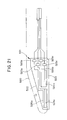
- Fig. 21 is a side view of a heat generating element mounted on one jaw of a pair of the jaws in the surgical instrument.
- heat generating patterns 524a and 524b e.g., thin film resistance heating elements divided into two parts, for example, a front portion and a rear portion, are disposed on the side surface in the vicinity of an edge portion 523 of the heat generating element 522 mounted on the side-surface side in the inside of the jaw 520.
- Two terminal portions 525a and 525b of the heat generating pattern 524a and two terminal portions 525c and 525d of the heat generating pattern 524b are disposed on the proximal end portion 521 of the heat generating element 522.
- the terminal portions 525a and 525b are electrically connected to both end portions of the heat generating pattern 524a by a lead pattern 526a.
- the terminal portions 525c and 525d are electrically connected to both end portions of the heat generating pattern 524b by a lead pattern 526b.
- the thus configured surgical instrument is used for heating a living-body tissue by taking advantage of heat generation of the heat generating patterns 524a and 524b disposed on the heat generating element 522 based on the electric power supplied from a power device, although not shown in the drawing, so that the living-body tissue is coagulated, for example.
- Japanese Unexamined Patent Application Publication No. 9-232102 discloses a heating member which is a heat generating element provided with a resistance layer on a metal substrate and which is used not only for a medical therapeutic instrument, but also for various purposes.
- the heating member will be described with reference to Fig. 22 and Fig. 23.
- the heating member 630 is composed of a substrate 631 made of anodized aluminum, aluminum, stainless steel, enamel-coated steel, copper, or the like, an electrically insulating layer 632 disposed on the substrate 631 and made of a silicone resin containing a thermally conductive filler, an electrical resistance layer 633 disposed on the electrically insulating layer 632 and made of a silicone resin containing an electrically conductive filler, an electrically conductive region 634 disposed on a part of the electrical resistance layer 633, and an insulating protective coating layer 635 disposed on the electrical resistance layer 633.
- the resistance against high temperatures and high power densities can be improved.
- the heat generating plate 412 is formed into the shape of a taper having a width decreasing with increasing proximity to the lower end edge, as shown in Fig. 19 and Fig. 20 and, therefore, there is a problem in that it is difficult to form a patterned resistor on a tapered surface.
- the heat generating element 522 is mounted on the side-surface side of the inside of the jaw 520, when the jaw 520 must be designed to take on a curved shape, the shape of the heat generating element 522 must be agreed with the curved shape. Consequently, there is a problem in that it is difficult to dispose the heat generating patterns 524a and 524b on the curved surface.
- the substrate 631 is composed of anodized aluminum, aluminum, stainless steel, enamel-coated steel, copper, or the like
- the electrical resistance layer 633 serving as a heat generating portion is composed of a silicone resin or the like containing an electrically conductive filler. Consequently, strain occurs between the substrate 631 and the electrical resistance layer 633 due to the difference in coefficient of linear thermal expansion between the substrate 631 and the electrical resistance layer 633, and there is a problem in that the life of the heating member 630 is shortened.
- the present invention was made in consideration of the above-described problems. Accordingly, it is an object of the present invention to provide a heat generating element capable of improving the uniformity of the temperature distribution in heat generation, having high heat-generation resistance, being constructed into the shape of an arbitrary free-form, and exerting a highly efficient and reliable heat effect on a living body, as well as a medical therapeutic instrument implementing the same and a treatment apparatus.
- a heat generating element includes at least a substrate, an insulating film disposed on the substrate, a heat generating portion having a thin film resistor disposed on at least a part of the insulating film, and a protective film disposed on the above-described insulating film and the above-described heat generating portion, wherein the above-described substrate and the above-described heat generating portion are composed of the same member.
- a medical therapeutic instrument implementing a heat generating element includes the above-described heat generating element and a treatment portion provided with the heat generating element to heat a living body tissue by using the heat generated from the heat generating element and treat the living-body tissue, wherein the above-described heat generating element is mounted on the above-described treatment portion in such a manner that an outer surface of the above-described substrate of the heat generating element serves as a treatment surface in the treatment of the living-body tissue.
- a treatment apparatus includes the above-described medical therapeutic instrument and means to supply electric power to the above-described heat generating element disposed on the above-described medical therapeutic instrument.
- Fig. 1 is a perspective view of a heat generating element according to the first embodiment of the present invention.
- Fig. 2 is a sectional view of the section taken along a line II-II shown in Fig. 1.
- a heat generating element 116 is formed into the shape of a free-form surface, for example, a curved shape, in a longitudinal direction (hereafter referred to as principal axis direction).
- two heat generating zones 40 each composed of a heat generating portion 4 described below and, for example, two electrodes 20 connected to the heat generating portion 4, are disposed on the top surface 116a of the heat generating element 116 along the principal axis of the heat generating element 116.
- the electrode 20 is composed of a member suitable for wiring, e.g., copper, and transfers the electric power supplied from a power device, although not shown in the drawing, to the heat generating portion 4.
- the number of heat generating zones to be disposed are not limited to two, and may be one, or two or more in accordance with the length of the principal axis of the heat generating element 116.
- an insulating film 3 composed of, for example, a silicon nitride film is disposed on a substrate 2 composed of, for example, a high-melting point metal, molybdenum.
- the heat generating portion 4 made of a thin film resistor composed of the same member as that of the substrate 2 is disposed on the insulating film 3.
- a protective film 5 composed of, for example, a silicon nitride film is disposed on the heat generating portion 4 and the insulating film 3.
- the substrate 2, the insulating film 3, the heat generating portion 4, and the protective film 5 are disposed integrally.
- the member of the substrate 2 is not limited to molybdenum.
- the substrate 2 may be composed of a member having a high heat conductivity. Examples thereof include high-melting point metals, alloys, and semiconductors, and specifically, noble metals, nickel-chromium, silicon, and tungsten.
- the insulating film 3 composed of a silicon nitride film having a thickness of, for example, 50 to 2,000 nm is formed all over the substrate 2 composed of molybdenum through deposition by, for example, low pressure chemical vapor deposition (LP-CVD).
- LP-CVD low pressure chemical vapor deposition
- the formation of the insulating film 3 is not limited to the deposition of the silicon nitride film, and may be performed by printing, application, and the like of other inorganic insulating films or organic insulating films.
- the insulating film 3 is made of a material having a coefficient of linear thermal expansion close to that of the substrate 2. Since the substrate 2 is composed of molybdenum having a coefficient of linear thermal expansion of 5.44 ⁇ 10 -6 /K at room temperature, the insulating film 3 is composed of a silicon nitride film having the same order of coefficient of linear expansion, that is, 3.00 ⁇ 10 -6 /K to 3.50 ⁇ 10 -6 /K.
- the heat generating portion 4 composed of a thin film resistor made of molybdenum, which is the same material as that of the molybdenum substrate 2, is formed on at least a part of the insulating film 3 in such a manner that the resulting film has a thickness capable of ensuring a heating value required for treating a living body, for example, a thickness of 50 to 2,000 nm, and takes on the shape of, for example, a letter U along the principal axis of the heat generating element 116, as shown in Fig. 1.
- the formation of the heat generating portion 4 on the insulating film 3 is performed by, for example, a method in which molybdenum is deposited and patterned simultaneously by using a mask patterned into a desired shape of a letter U in evaporation or sputtering, or a method in which molybdenum is deposited all over the insulating film 3 and, thereafter, is photo-etched into the shape of a letter U.
- the member of the insulating film 4 is not limited to molybdenum.
- the insulating film 4 may also be formed from a high-melting point metal, an alloy, or a semiconductor, e.g., a noble metal, nickel-chromium, silicon, or tungsten, as long as the member is the same as that of the substrate 2.
- the protective film 5 composed of a silicon nitride film having a thickness of about 1.5 ⁇ m is formed on the heat generating portion 4 and the insulating film 3 through deposition by, for example, LP-CVD.
- the formation of the protective film 5 is not limited to the deposition of the silicon nitride film, and may be performed by printing, application, and the like of other inorganic insulating films or organic insulating films.
- the protective film 5 is also made of a material having a coefficient of linear thermal expansion close to that of the substrate 2 and the heat generating portion 4, as in the insulating film 3.
- Holes are formed in the protective film 5 on two proximal ends of each of two heat generating portions 4 in the shape of a letter U by using photo-etching.
- Four electrodes 20, that is, two electrodes 20 per heat generating zone 40, are formed from, for example, copper to have a thickness of, for example, 0.1 to 30 ⁇ m while covering the holes.
- the formation of the electrodes 20 is performed by, for example, a method in which copper is deposited and patterned simultaneously by using a mask patterned into a desired shape in evaporation, sputtering, or plating, or a method in which copper is deposited all over the surface and, thereafter, is photo-etched into a desired shape.
- the substrate 2 is formed into, for example, a substantially convex shape pointing downward through cutting by dicing, NC cutting, or the like.
- the heat generating element 116 is formed through the above-described steps.
- the substrate 2 and the heat generating portion 4 constituting the heat generating element 116 are composed of the same member. Therefore, there is almost no difference in coefficient of linear thermal expansion between the substrate 2 and the heat generating portion 4, so that the heat generating portion 4 is hardly influenced by strain due to the substrate 2 when heat is generated from the heat generating element 116. Consequently, no strain occur between the substrate 2 and the heat generating portion 4, the heat-generation resistance of the heat generating element 116 can be improved, and the heat generating element having a high heat-generation resistance can be provided.
- the insulating film 3 and the protective film 5 are composed of the silicon nitride film having a coefficient of linear thermal expansion of 3.00 ⁇ 10 -6 /K to 3.50 ⁇ 10 -6 /K close to the coefficient of linear thermal expansion of the substrate 2 of 5.44 ⁇ 10 -6 /K, so that an influence exerted on the heat generating portion 4 by strain due to the protective film 5 is reduced when heat is generated from the heat generating portion 4 of the heat generating element 116. Consequently, the heat-generation resistance of the heat generating element 116 can be improved, and the heat generating element 116 having a high heat-generation resistance can be provided.
- the member of the substrate 2 is not limited to molybdenum.
- the substrate 2 may be composed of a member having a high heat conductivity. Examples thereof include high-melting point metals, alloys, and semiconductors, and specifically, noble metals, nickel-chromium, silicon, and tungsten. Since the heat generating zones 40, each provided with a heat generating portion 4, is disposed along the principal axis of the heat generating element 116, even when the heat generating element 116 is long-disposed in the principal axis direction, the uniformity of the temperature distribution of the heat generating element 116 can be improved in the heat generation.
- the heat generating portion 4 constituting the heat generating zone 40 is formed into the shape of a letter U along the principal axis of the heat generating element 116.
- the shape is not limited to this, and the heat generating portion 4 may be formed into any shape, as a matter of course.
- each heat generating portion 4 is disposed on the proximal ends of each heat generating portions 4 in the shape of a letter U.
- the number of electrodes is not limited to this, and any number of electrodes may be disposed, as a matter of course.
- Fig. 3 is a front view showing a configuration of a treatment apparatus including a heat coagulation cutting forceps for open surgery, the forceps serving as a medical therapeutic instrument, and a power device according to the second embodiment of the present invention.
- Fig. 4 is a sectional view of a distal end portion of the heat coagulation cutting forceps for open surgery shown in Fig. 3.
- Fig. 5 is a sectional view of the section taken along a line V-V shown in Fig. 3.
- Fig. 6 is a magnified perspective view of the heat generating element shown in Fig. 3.
- the heat generating element 116 according to the above-described first embodiment is used for a heat coagulation cutting forceps for open surgery, the forceps serving as a medical therapeutic instrument, or a treatment apparatus including the heat coagulation cutting forceps for open surgery and a power device according to the second embodiment. Therefore, in the description of the present embodiment, the heat generating element 116 described in the first embodiment is indicated by the same reference numeral, and further explanations of the configuration thereof will not be provided.
- a key portion of a treatment apparatus 101 is composed of a heat coagulation cutting forceps for open surgery (hereafter simply referred to as forceps) 102 and a power device 103.
- the forceps 102 is used for subjecting a living-body tissue in a body cavity to various treatments, e.g., coagulation and cutting, by taking advantage of the heat generated based on the electric power supplied.
- the power device 103 is power supply means for controlling the thermal driving of the forceps 102 by supplying electric power to the forceps 102.
- the key portion of the forceps 102 is composed of a first forceps body 105 composed of a rod-shaped member and a second forceps body 107 composed of a rod-shaped member rotatably mounted on the first forceps body 105 through a pivot 106 serving as a pivotal portion.
- a second jaw 109 formed into the shape having a principal axis in a curved shape is disposed on the distal-end side of the second forceps body 107.
- the first jaw 108 pairs off with the second jaw 109 and constitutes a treatment portion 110.
- a first arm 111 is disposed on the rear side of the first forceps body 105, and a first ring 112 for insertion of a finger is disposed on the proximal-end side of the first arm 111.
- a cord connection portion 128 is disposed on the proximal end portion of the first ring 112.
- a second arm 113 is disposed on the rear side of the second forceps body 107 as in the first forceps body 105, and a second ring 114 for insertion of a finger is disposed on the proximal-end side of the second arm 113.
- the first arm 111, the second arm 113, the first ring 112, and the second ring 114 constitute a control portion 115 to perform opening and closing operations of a pair of the first jaw 108 and the second jaw 109 constituting the treatment portion 110.
- a heat generating element 116 to apply thermal energy to a living-body tissue is disposed on the first jaw 108 while being located at the position facing the second jaw 109.
- the heat generating element 116 is mounted on a concave portion 108a formed along the principal axis, on the surface of the first jaw 108 facing the second jaw 109.
- the heat generating element 116 is mounted along the principal axis, on a concave portion 108a with a heat insulating member 122 (refer to Fig. 5), described below, therebetween in such a manner that the treatment surface 2at, described below, of the substrate 2 is located to face the second jaw 109.
- the heat generating element 116 may be mounted on the second jaw 109.
- the heat generating elements may be mounted on both the first jaw 108 and the second jaw 109.
- the configuration of the heat generating element 116 is substantially the same as the heat generating element 116 according to the first embodiment described above with reference to Fig. 1 or Fig. 2. However, the principal axis of the heat generating element 116 is formed into the shape in agreement with the curved shape of the principal axis of the first jaw 108. In this manner, the heat generating element 116 can readily be disposed on the first jaw 108 even though the first jaw 108 is in the curved shape.
- the position 2at which is a perimeter surface 2a of the substrate 2 in the convex shape pointing downward of the heat generating element 116 and which faces the second jaw 109 serves as a treatment surface in the treatment of, for example, a living-body tissue.
- the treatment surface 2at is in a blunt shape.
- the treatment surface 2at is constructed into the shape of a partial arc which is a free-form surface and which has a diameter substantially equal to the width of the heat generating element 116.
- the treatment surface 2at is constructed to have a cross section in the shape of a partial arc which is a free-form surface, the cross section being substantially perpendicular to a longitudinal direction of the heat generating element 116.
- the perimeter surface 2a (refer to Fig. 2) of the substrate 2 substantially in the convex shape pointing downward of the heat generating element 116 may be provided with a non-adhesive coating made of polytetrafluoroethylene (PTFE) or the like in order to prevent sticking of a living-body tissue in the treatment of the living-body tissue.
- PTFE polytetrafluoroethylene
- lead wires 124, 125, 126, and 127 are connected and fixed to respective electrodes 20 disposed on the top surface 116a of the heat generating element 116.
- the connection and fixing can be performed by welding, brazing, soldering, or the like.
- a heat insulating member 122 made of a material having a low thermal conductivity and high heat resistance, e.g., polytetrafluoroethylene (PTFE) or a high-performance thermoplastic resin (PEEK (registered trademark)).
- PTFE polytetrafluoroethylene
- PEEK high-performance thermoplastic resin
- the heat insulating member 122 is fit and fixed to the concave portion 108a disposed along the principal axis on the first jaw 108. As shown in Fig. 4, the heat generating element 116 is fixed to the heat insulating member 122 or the first jaw 108 along the principal axis by using pins 121 for fixing a heat generating element.
- a receiving member 123 is disposed on the second jaw 109 while being located at the position facing the heat generating element 116 mounted on the first jaw 108.
- the receiving member 123 is formed from a resin material, e.g., silicone rubber, fluororubber, or PTFE.
- the lead wires 124 to 127 connected and fixed to the electrodes 20 of the heat generating element 116 are connected to the cord connection portion 128 disposed at the proximal end portion of the first ring 112 disposed on the proximal-end side of the forceps 102.
- connection cord 129 is connected to a power device 103, and the other end is connected to the cord connection portion 128.
- a foot switch 104 to perform ON/OFF control of the electric power of the power device 103 is connected to the power device 103 through a foot switch cord 130.
- a surgeon positions the living-body tissue in between the first jaw 108 and the second jaw 109 of the forceps 102.
- the surgeon grasps the living-body tissue between the treatment surface 2at of the heat generating element 116 mounted on the first jaw 108 and the receiving member 123 of the second jaw 109 by operating the control portion 115 to close the forceps 102 while the living-body tissue is positioned in between the first jaw 108 and the second jaw 109 of the forceps 102.
- the surgeon After grasping the living-body tissue, the surgeon operates the foot switch 104 so that electric power is supplied from the power device 103 through the connection cord 129, the cord connection portion 128, and the lead wires 124 to 127 to the heat generating element 116, the heat generating portion 4 of the heat generating element 116 is made to generate heat, and the living-body tissue is subjected to a treatment, e.g., coagulation or cutting.
- a treatment e.g., coagulation or cutting.
- the heat generating portion 4 and the treatment surface 2at have been integrated in the heat generating element 116, the efficiency of heat transfer from the heat generating portion 4 to the treatment surface 2at can be significantly increased. Since the heat generating portion 4 is disposed on the top surface of the treatment surface 2at, put another way, on the surface opposite to the treatment surface 2at, as shown in Fig. 6, the heat generating portion 4 can readily be formed even when the heat generating element 116 is in a curved shape along the principal axis.
- the electric power is supplied from the power device 103 to the heat generating element 116 by any one of a constant voltage system, a constant current system, and a constant power system, and may be controlled in such a way that the power supply is interrupted or the power supply system is switched when the temperature, time, cumulative amount of power, or the like reaches a threshold value.
- the power supply from the power device 103 to the heat generating element 116 may be controlled in such a way that the temperature of the heat generating element 116 is always kept constant or is changed stepwise.
- This control may be combined with the above-described control in which the power supply is interrupted or the power supply system is switched when a threshold value is reached.
- the heat generating element 116 according to the first embodiment is disposed on the first jaw 108, while the heat generating element 116 has high heat-generation resistance and the uniformity of the temperature distribution in the heat generation is improved, and the living-body tissue is grasped between the treatment surface 2at of the substrate 2 of the heat generating element 116 and the receiving member 123 of the second jaw 109.
- the heat generating portion 4 and the treatment surface 2at of the substrate 2 is integrated in the heat generating element 116.
- the treatment surface 2at of the substrate 2 of the heat generating element 116 is in a blunt shape, and is constructed into the shape of a partial arc which is a free-form surface and which has a diameter substantially equal to the width of the heat generating element 116.
- the shape of the treatment surface 2at is not limited to this, and may be changed in accordance with purposes of treatments. In general, as the shape of the treatment surface 2at becomes sharper, treatments, e.g., cutting, are readily performed, and as the shape becomes blunter, treatments, e.g., coagulation, are readily performed.
- the treatment surface 2at may be formed into a shape in which both sides are constructed by inclined surfaces and the distal end portion has a small radius of curvature, as shown in Fig. 7.
- the treatment surface 2at may be formed into a shape in which both edges are chamfered to have a small radius of curvature and the central portion has a flat portion, as shown in Fig. 8.
- the treatment surface 2at may be formed into the shape of a partial arc having a diameter larger than the width of the heat generating element 116, as shown in Fig. 9.
- the treatment surface 2at may be formed into a shape in which both sides of the heat generating element are constructed by inclined surfaces and the distal end portion is made flat, as shown in Fig. 10.
- Fig. 11 is a front view showing a configuration of a treatment apparatus including a heat coagulation cutting forceps for laparoscopic surgery, the forceps serving as a medical therapeutic instrument, and a power device according to a third embodiment of the present invention.
- Fig. 12 is a sectional view of a distal end portion of the heat coagulation cutting forceps for laparoscopic surgery shown in Fig. 11.
- Fig. 13 is a sectional view of the section taken along a line XIII-XIII shown in Fig. 12.
- the heat generating element 116 according to the above-described first embodiment is used for a heat coagulation cutting forceps for laparoscopic surgery, the forceps serving as a medical therapeutic instrument, or a treatment apparatus including the heat coagulation cutting forceps for laparoscopic surgery and a power device. Therefore, in the description of the present embodiment, the heat generating element 116 described in the first embodiment is indicated by the same reference numeral, and further explanations of the configuration thereof will not be provided.
- the configuration of the heat coagulation cutting forceps for laparoscopic surgery or the treatment apparatus including the heat coagulation cutting forceps for laparoscopic surgery and the power device of the present embodiment is different from the configuration of the heat coagulation cutting forceps for open surgery 102 or the treatment apparatus 101 including the heat coagulation cutting forceps for open surgery 102 and the power device 103 shown in Fig. 3 to Fig. 10 in that the heat generating element 116 is disposed on the heat coagulation cutting forceps for laparoscopic surgery. Therefore, only this dissimilarity will be described.
- the configurations similar to those in the second embodiment are indicated by the same reference numerals, and further explanations thereof will not be provided.
- a treatment apparatus 201 has a configuration including a heat coagulation cutting forceps for laparoscopic surgery (hereafter simply referred to as forceps) 202 used for subjecting a living-body tissue in a body cavity to various treatments, e.g., coagulation and cutting, by taking advantage of the heat generated based on the electric power supplied from the power device 103 serving as power supply means.
- forceps heat coagulation cutting forceps for laparoscopic surgery
- the forceps 202 is provided with a slender insertion portion 208, a treatment portion 207 disposed on the distal-end side of the insertion portion 208, and a control portion 213 disposed on the proximal-end side of the insertion portion 208.
- the treatment portion 207 is composed of a pair of grasp portions which can be optionally opened and closed, for example, a first jaw 205 formed to have a principal axis in a curved shape, which is a free-form surface, and a second jaw 206 formed into the shape having a principal axis in a curved shape.
- the first jaw 205 is formed into the shape in agreement with the shape of the principal axis of the heat generating element 116.
- a key portion of the control portion 213 is composed of a control portion main body 209, a first handle (hereafter referred to as fixed handle) 210 disposed integrally with the control portion main body 209, a second handle (hereafter referred to as movable handle) 211 rotatably attached to the fixed handle 210 through a pivot 212.
- a first handle hereafter referred to as fixed handle
- a second handle hereafter referred to as movable handle
- the control portion main body 209 is provided with a rotation control portion 214 to rotate the insertion portion 208 about the center of axis of the insertion portion 208 in circumferential directions of the axis.
- an outer tube 251 formed from a pipe having a small diameter is disposed in the insertion portion 208.
- a channel pipe 252 and a driving shaft channel 253 are parallel disposed along the principal axis in the inside of the outer tube 251.
- An insertion space 254 is disposed in the inside of the channel pipe 252, and lead wires 124 to 127 to be connected to the heat generating element 116 are inserted through the channel pipe 252. Furthermore, a driving shaft 215 is inserted through the driving shaft channel 253 in such a manner that the driving shaft 215 can be moved optionally in the principal axis direction. As shown in Fig. 11, the proximal end portion of the driving shaft 215 is coupled to a movable handle 211. The driving shaft 215 is driven to move in the principal axis direction while being operatively associated with the opening and closing operation of the movable handle 211.
- a bifurcated support member 255 protruding toward the front is disposed at the distal end portion of the insertion portion 208.
- the proximal-end side of the support member 255 in the principal axis direction is fixed to the front end of the outer tube 251.
- a pivot pin 256 serving as a pivotal portion is disposed at the bifurcated distal end portion of the support member 255 while penetrating the support member 255 in the direction of penetration.
- the proximal end portion of the second jaw 206 in the principal axis direction is rotatably fixed to the support member 255 through the pivot pin 256.
- the proximal end portion of the first jaw 205 in the principal axis direction is coupled to the driving shaft 215 through a coupling pin 257.
- the proximal end portion of the second jaw 206 is rotatably fixed to the proximal end portion of the first jaw 205 through a connection pin 258.
- the driving shaft 215 is driven to move to and fro.
- the first jaw 205 having the proximal end portion coupled to the driving shaft 215 is opened and closed relative to the second jaw 206.
- first jaw 205 and the second jaw 206 are similar to the configuration in the above-described second embodiment. As shown in Fig. 12 and Fig. 13, the first jaw 205 is provided with a heat generating element 116, a heat insulating member 122, and the like, and the second jaw 206 is provided with a receiving member 123 and the like.
- the heat generating element 116 according to the first embodiment is disposed on the first jaw 205, while the heat generating element 116 has high heat-generation resistance and the uniformity of the temperature distribution in the heat generation is improved, and as shown in Fig. 12 and Fig. 13, the living-body tissue is grasped between the treatment surface 2at of the substrate 2 of the heat generating element 116 and the receiving member 123 of the second jaw 206.
- the heat generating portion 4 and the treatment surface 2at of the substrate 2 is integrated in the heat generating element 116.
- the first jaw 205 of the forceps 202 can also be formed into the curved shape along the principal axis. Therefore, the operability in the treatment, e.g., dissecting of the living-body tissue, can be improved.
- the treatment surface 2at of the substrate 2 of the heat generating element 116 is in a blunt shape, and is constructed into the shape of a partial arc which is an arbitrary free-form surface and which has a diameter substantially equal to the width of the heat generating element 116, as shown in Fig. 13, similarly to that in the above-described second embodiment.
- the shape of the treatment surface 2at is not limited to this, and may be changed in accordance with purposes of treatments.
- the shape may be similar to those shown in Fig. 7 to Fig. 10 in the above-described second embodiment.
- Fig. 14 is a front view showing a configuration of a treatment apparatus including a heat coagulation probe serving as a medical therapeutic instrument and a power device according to the fourth embodiment of the present invention.
- Fig. 15 is a sectional view of a distal end portion of the heat coagulation probe shown in Fig. 14.
- Fig. 16 is a perspective view of a heat generating element disposed at the distal end of a shaft of the heat coagulation probe shown in Fig. 14.
- Fig. 17 is a sectional view of the section taken along a line XVII-XVII shown in Fig. 16.
- the heat generating element 116 according to the above-described first embodiment is used for a heat coagulation probe serving as a medical therapeutic instrument or a treatment apparatus including the heat coagulation probe and a power device according to the fourth embodiment. Therefore, in the description of the fourth embodiment, the heat generating element 116 described in the first embodiment is indicated by the same reference numeral, and further explanations of the configuration thereof will not be provided.
- the configuration of the heat coagulation probe or the treatment apparatus including the heat coagulation probe and the power device of the present embodiment is different from the configuration of the heat coagulation cutting forceps for open surgery 102 and the treatment apparatus 101 shown in the above-described Fig. 3 to Fig. 10 and the configuration of the heat coagulation cutting forceps for laparoscopic surgery 202 and the treatment apparatus 201 shown in the above-described Fig. 11 to Fig. 13 in that the heat generating element 116 is deformed in agreement with the shape of the distal end of the heat coagulation probe, and is disposed at the distal end of the heat coagulation probe. Therefore, only this dissimilarity will be described.
- the configurations similar to those in the second embodiment and the third embodiment are indicated by the same reference numerals, and further explanations thereof will not be provided.
- a treatment apparatus 301 has a configuration including a heat coagulation probe (hereafter simply referred to as probe) 302 used for subjecting a living-body tissue to various treatments, e.g., coagulation, by taking advantage of the heat generated based on the electric power supplied from the power device 103 serving as power supply means.
- probe heat coagulation probe
- the probe 302 is provided with a slender shaft 351, a treatment portion 356 disposed on the distal-end side of the shaft 351, and a grip 352 disposed on the proximal-end side of the shaft 351.
- the proximal end portion of the shaft 351 is mounted on the distal end of the grip 352 by screw coupling, for example.
- a cord connection portion 128 is disposed on the proximal end portion of the grip 352.
- a protective tube 354 is disposed in the inside of the shaft 351, and the above-described lead wires 124 to 127 are inserted through the inside of the protective tube 354.
- the treatment portion 356 is disposed on the distal end portion of the shaft 351.
- the treatment portion 356 is composed of the above-described heat insulating member 122 and the heat generating element 116.
- the heat insulating member 122 is formed into a substantially convex shape with steps, and a first projection 122a is fit into the inner perimeter on the distal-end side of the protective tube 354.
- a second projection 122b of the heat insulating member 122 is fit into the inside of the shaft 351 with a watertight O-ring 353 therebetween and is fixed by screw coupling, for example. Furthermore, the lead wires 124 to 127 are also inserted through the inside of the heat insulating member 122.
- a hole portion 122ch is bored in the surface on the distal-end side of a base portion 122c of the heat insulating member 122, and the heat generating element 116 is fit into the hole portion 122ch with a watertight O-ring 353 therebetween and is fixed by screw coupling, for example.
- the heat generating element 116 is composed of a cylindrical fitting portion 2k in the shape of an outward flange having a small diameter and a hemispherical portion 2s which is connected to the end portion of the fitting portion 2k and which has an outer surface 2a in the shape of a free-form surface constituting a treatment surface 2at.
- the treatment surface 2at may be constructed into the shape of other than a hemisphere.
- the treatment surface 2at of the hemispherical portion 2s may be provided with a non-adhesive coating made of polytetrafluoroethylene (PTFE) or the like in order to prevent sticking of a living-body tissue in pealing of the living-body tissue.
- PTFE polytetrafluoroethylene
- the fitting portion 2k of the thus configured heat generating element 116 is fit into the hole portion 122ch of the heat insulating member 122 and is fixed by screw coupling, for example. At this time, the ends of the lead wires 124 to 127 are connected to the electrodes 20 of the heat generating element 116, as described above.
- a surgeon brings the treatment surface 2at of the heat generating element 116 fixed to the distal end of the probe 302 into contact with the living-body tissue.
- the surgeon operates the foot switch 104 so that electric power is supplied from the power device 103 serving as power supply means through the connection cord 129, the cord connection portion 128, and the lead wires 124 to 127 to the heat generating element 116, the heat generating portion 4 of the heat generating element 116 is made to generate heat, and the living-body tissue is subjected to a treatment, e.g., coagulation.
- a treatment e.g., coagulation
- the heat generating element 116 according to the first embodiment is disposed on the distal end of the shaft 351, while the heat generating element 116 has high heat-generation resistance and the uniformity of the temperature distribution in the heat generation is improved, and the treatment surface 2at of the substrate 2 of the heat generating element 116 is brought into contact with the living-body tissue.
- the heat generating portion 4 and the treatment surface 2at of the substrate 2 are integrated in the heat generating element 116.
- the medical therapeutic instrument is exemplified by the probe.
- the medical therapeutic instrument is not limited to this, and as a matter of course, any medical therapeutic instrument may be applied as long as a living-body tissue is treated by an application of heat.
- the heat generating element 116 is composed of the cylindrical fitting portion 2k in the shape of an outward flange having a small diameter and the hemispherical portion 2s which is connected to the end portion of the fitting portion 2k and which has the outer surface 2a in the shape of a free-form surface constituting the treatment surface 2at.
- the structure is not limited to this, and any structure may be adopted as long as the heat generating element can be fixed to the distal end of the shaft 351.
- the treatment surface 2at may formed into an optimum shape selected in accordance with the purpose of the treatment, as a matter of course.
Abstract
A heat generating element of the present invention
includes at least a substrate, an insulating film disposed
on the substrate, a heat generating portion provided with a
thin film resistor disposed on at least a part of the
insulating film, and a protective film disposed on the
above-described insulating film and the above-described heat
generating portion, wherein the above-described substrate
and the above-described heat generating portion are composed
of the same member. A medical therapeutic instrument of the
present invention includes a treatment portion provided with
the above-described heat generating element to heat a living
body tissue by using the heat generated from the heat
generating element and treat the living-body tissue, wherein
the above-described heat generating element is mounted on
the above-described treatment portion in such a manner that
an outer surface of the above-described substrate of the
heat generating element serves as a treatment surface.
Description
The present invention relates to a heat generating
element which generates heat in the treatment of a living
body tissue by heating, a medical therapeutic instrument
implementing the heat generating element, and a treatment
apparatus.
Various medical accessories have been previously
proposed. The medical accessories are inserted into body
cavities to heat living-body tissues and, for example,
coagulate the living-body tissues.
For example, Japanese Patent No. 3523839 discloses a
surgical instrument serving as a medical therapeutic
instrument having a pair of jaws which are opened and closed
through a pivotal portion disposed at the proximal end
portions. The above-described surgical instrument will be
described with reference to Fig. 18 to Fig. 20.
Fig. 18 is a sectional view of distal-end portions of a
pair of jaws. Fig. 19 is a sectional view of the section
taken along a line XIX-XIX shown in Fig. 18. As shown in
the drawings, a heat generating plate 412 is disposed on the
distal-end portion side in the inside of the jaw 406 which
is one of the pair of jaws 406 and 407 in the surgical
instrument, and the heat generating plate 412 is in the
shape of a taper having a width decreasing with increasing
proximity to a lower end edge, as shown in Fig. 19. An
exposed portion of the heat generating plate 412 constitutes
a treatment surface in the treatment of a living-body tissue
by heating, coagulating, cutting, and the like.
Thin film resistance heating elements 453a, 453b, and
453c are disposed on the perimeter surface of the exposed
portion of the heat generating plate 412, that is, on the
treatment surface. The thin film resistance heating
elements 453a, 453b, and 453c are electrically connected to
a lead wire 418 on the proximal-end side of the jaw 406, as
shown in Fig. 18.
Fig. 20 is a magnified diagram of the heat generating
plate 412 in Fig. 19. As shown in the drawing, the thin
film resistance heating elements 453a, 453b, and 453c are
formed by superimposing an insulating layer 454, a resistor
455 serving as a heat generating portion, a protective layer
451, and a Teflon coating layer 456 on the heat generating
plate 412 in that order to constitute a four-layer structure.
Therefore, the resistor 455 is disposed on the treatment
surface side.
The thus configured surgical instrument is used for
heating a living-body tissue by taking advantage of heat
generation of the resistor 455 of the thin film resistance
heating elements 453a, 453b, and 453c disposed on the heat
generating plate 412 based on the electric power supplied
from a power device, although not shown in the drawing, so
as to, for example, coagulate the living-body tissue.
Japanese Unexamined Patent Application Publication No.
2003-70801 discloses a surgical instrument including a pair
of jaws which can be optionally opened and closed and serves
as a medical therapeutic instrument used for heating a
living-body tissue to, for example, coagulate the living-body
tissue. The above-described surgical instrument will
be described with reference to Fig. 21.
Fig. 21 is a side view of a heat generating element
mounted on one jaw of a pair of the jaws in the surgical
instrument. As shown in the drawing, heat generating
patterns 524a and 524b, e.g., thin film resistance heating
elements divided into two parts, for example, a front
portion and a rear portion, are disposed on the side surface
in the vicinity of an edge portion 523 of the heat
generating element 522 mounted on the side-surface side in
the inside of the jaw 520.
Two terminal portions 525a and 525b of the heat
generating pattern 524a and two terminal portions 525c and
525d of the heat generating pattern 524b are disposed on the
proximal end portion 521 of the heat generating element 522.
The terminal portions 525a and 525b are electrically
connected to both end portions of the heat generating
pattern 524a by a lead pattern 526a. The terminal portions
525c and 525d are electrically connected to both end
portions of the heat generating pattern 524b by a lead
pattern 526b.
The thus configured surgical instrument is used for
heating a living-body tissue by taking advantage of heat
generation of the heat generating patterns 524a and 524b
disposed on the heat generating element 522 based on the
electric power supplied from a power device, although not
shown in the drawing, so that the living-body tissue is
coagulated, for example.
In addition, Japanese Unexamined Patent Application
Publication No. 9-232102 discloses a heating member which is
a heat generating element provided with a resistance layer
on a metal substrate and which is used not only for a
medical therapeutic instrument, but also for various
purposes. The heating member will be described with
reference to Fig. 22 and Fig. 23.
Fig. 22 is a sectional view of the heating member, and
Fig. 23 is a top view of the heating member shown in Fig. 22.
As shown in the drawings, the heating member 630 is composed
of a substrate 631 made of anodized aluminum, aluminum,
stainless steel, enamel-coated steel, copper, or the like,
an electrically insulating layer 632 disposed on the
substrate 631 and made of a silicone resin containing a
thermally conductive filler, an electrical resistance layer
633 disposed on the electrically insulating layer 632 and
made of a silicone resin containing an electrically
conductive filler, an electrically conductive region 634
disposed on a part of the electrical resistance layer 633,
and an insulating protective coating layer 635 disposed on
the electrical resistance layer 633.
According to the above-described configuration of the
heating member 630, the resistance against high temperatures
and high power densities can be improved.
However, in the surgical instrument disclosed in
Japanese Patent No. 3523839, the heat generating plate 412
is formed into the shape of a taper having a width
decreasing with increasing proximity to the lower end edge,
as shown in Fig. 19 and Fig. 20 and, therefore, there is a
problem in that it is difficult to form a patterned resistor
on a tapered surface.
In the surgical instrument disclosed in Japanese
Unexamined Patent Application Publication No. 2003-70801,
since the heat generating patterns 524a and 524b are
disposed on the side surface of the heat generating element
522, as shown in Fig. 21, there is a problem in that the
temperature becomes one-sided in the width direction of the
heat generating element when the heat generating element 522
must be designed to have a large width. Therefore,
optimization of the temperature distribution is required.
Furthermore, since the heat generating element 522 is
mounted on the side-surface side of the inside of the jaw
520, when the jaw 520 must be designed to take on a curved
shape, the shape of the heat generating element 522 must be
agreed with the curved shape. Consequently, there is a
problem in that it is difficult to dispose the heat
generating patterns 524a and 524b on the curved surface.
In the heating member disclosed in Japanese Unexamined
Patent Application Publication No. 9-232102, as shown in Fig.
22, the substrate 631 is composed of anodized aluminum,
aluminum, stainless steel, enamel-coated steel, copper, or
the like, and the electrical resistance layer 633 serving as
a heat generating portion is composed of a silicone resin or
the like containing an electrically conductive filler.
Consequently, strain occurs between the substrate 631 and
the electrical resistance layer 633 due to the difference in
coefficient of linear thermal expansion between the
substrate 631 and the electrical resistance layer 633, and
there is a problem in that the life of the heating member
630 is shortened.
The present invention was made in consideration of the
above-described problems. Accordingly, it is an object of
the present invention to provide a heat generating element
capable of improving the uniformity of the temperature
distribution in heat generation, having high heat-generation
resistance, being constructed into the shape of an arbitrary
free-form, and exerting a highly efficient and reliable heat
effect on a living body, as well as a medical therapeutic
instrument implementing the same and a treatment apparatus.
A heat generating element according to an aspect of the
present invention includes at least a substrate, an
insulating film disposed on the substrate, a heat generating
portion having a thin film resistor disposed on at least a
part of the insulating film, and a protective film disposed
on the above-described insulating film and the above-described
heat generating portion, wherein the above-described
substrate and the above-described heat generating
portion are composed of the same member.
A medical therapeutic instrument implementing a heat
generating element according to another aspect of the
present invention includes the above-described heat
generating element and a treatment portion provided with the
heat generating element to heat a living body tissue by
using the heat generated from the heat generating element
and treat the living-body tissue, wherein the above-described
heat generating element is mounted on the above-described
treatment portion in such a manner that an outer
surface of the above-described substrate of the heat
generating element serves as a treatment surface in the
treatment of the living-body tissue.
Furthermore, a treatment apparatus according to another
aspect of the present invention includes the above-described
medical therapeutic instrument and means to supply electric
power to the above-described heat generating element
disposed on the above-described medical therapeutic
instrument.
The above and other objects, features and advantages of
the invention will become more clearly understood from the
following description referring to the accompanying drawings.
The embodiments of the present invention will be
described below with reference to the drawings.
Fig. 1 is a perspective view of a heat generating
element according to the first embodiment of the present
invention. Fig. 2 is a sectional view of the section taken
along a line II-II shown in Fig. 1.
As shown in Fig. 1, a heat generating element 116 is
formed into the shape of a free-form surface, for example, a
curved shape, in a longitudinal direction (hereafter
referred to as principal axis direction).
For example, two heat generating zones 40, each
composed of a heat generating portion 4 described below and,
for example, two electrodes 20 connected to the heat
generating portion 4, are disposed on the top surface 116a
of the heat generating element 116 along the principal axis
of the heat generating element 116.
The electrode 20 is composed of a member suitable for
wiring, e.g., copper, and transfers the electric power
supplied from a power device, although not shown in the
drawing, to the heat generating portion 4. The number of
heat generating zones to be disposed are not limited to two,
and may be one, or two or more in accordance with the length
of the principal axis of the heat generating element 116.
As shown in Fig. 2, an insulating film 3 composed of,
for example, a silicon nitride film is disposed on a
substrate 2 composed of, for example, a high-melting point
metal, molybdenum. The heat generating portion 4 made of a
thin film resistor composed of the same member as that of
the substrate 2 is disposed on the insulating film 3. A
protective film 5 composed of, for example, a silicon
nitride film is disposed on the heat generating portion 4
and the insulating film 3. The substrate 2, the insulating
film 3, the heat generating portion 4, and the protective
film 5 are disposed integrally.
The member of the substrate 2 is not limited to
molybdenum. The substrate 2 may be composed of a member
having a high heat conductivity. Examples thereof include
high-melting point metals, alloys, and semiconductors, and
specifically, noble metals, nickel-chromium, silicon, and
tungsten.
A method for manufacturing the thus configured heat
generating element 116 will be briefly described below.
The insulating film 3 composed of a silicon nitride
film having a thickness of, for example, 50 to 2,000 nm is
formed all over the substrate 2 composed of molybdenum
through deposition by, for example, low pressure chemical
vapor deposition (LP-CVD). The formation of the insulating
film 3 is not limited to the deposition of the silicon
nitride film, and may be performed by printing, application,
and the like of other inorganic insulating films or organic
insulating films.
Desirably, the insulating film 3 is made of a material
having a coefficient of linear thermal expansion close to
that of the substrate 2. Since the substrate 2 is composed
of molybdenum having a coefficient of linear thermal
expansion of 5.44 × 10⁻⁶/K at room temperature, the
insulating film 3 is composed of a silicon nitride film
having the same order of coefficient of linear expansion,
that is, 3.00 × 10⁻⁶/K to 3.50 × 10⁻⁶/K.
The heat generating portion 4 composed of a thin film
resistor made of molybdenum, which is the same material as
that of the molybdenum substrate 2, is formed on at least a
part of the insulating film 3 in such a manner that the
resulting film has a thickness capable of ensuring a heating
value required for treating a living body, for example, a
thickness of 50 to 2,000 nm, and takes on the shape of, for
example, a letter U along the principal axis of the heat
generating element 116, as shown in Fig. 1.
The formation of the heat generating portion 4 on the
insulating film 3 is performed by, for example, a method in
which molybdenum is deposited and patterned simultaneously
by using a mask patterned into a desired shape of a letter U
in evaporation or sputtering, or a method in which
molybdenum is deposited all over the insulating film 3 and,
thereafter, is photo-etched into the shape of a letter U.
The member of the insulating film 4 is not limited to
molybdenum. The insulating film 4 may also be formed from a
high-melting point metal, an alloy, or a semiconductor, e.g.,
a noble metal, nickel-chromium, silicon, or tungsten, as
long as the member is the same as that of the substrate 2.
The protective film 5 composed of a silicon nitride
film having a thickness of about 1.5 µm is formed on the
heat generating portion 4 and the insulating film 3 through
deposition by, for example, LP-CVD. As in the formation of
the insulating film 3, the formation of the protective film
5 is not limited to the deposition of the silicon nitride
film, and may be performed by printing, application, and the
like of other inorganic insulating films or organic
insulating films. Desirably, the protective film 5 is also
made of a material having a coefficient of linear thermal
expansion close to that of the substrate 2 and the heat
generating portion 4, as in the insulating film 3.
Holes are formed in the protective film 5 on two
proximal ends of each of two heat generating portions 4 in
the shape of a letter U by using photo-etching. Four
electrodes 20, that is, two electrodes 20 per heat
generating zone 40, are formed from, for example, copper to
have a thickness of, for example, 0.1 to 30 µm while
covering the holes.
The formation of the electrodes 20 is performed by, for
example, a method in which copper is deposited and patterned
simultaneously by using a mask patterned into a desired
shape in evaporation, sputtering, or plating, or a method in
which copper is deposited all over the surface and,
thereafter, is photo-etched into a desired shape.
Finally, the substrate 2 is formed into, for example, a
substantially convex shape pointing downward through cutting
by dicing, NC cutting, or the like. The heat generating
element 116 is formed through the above-described steps.
In this manner, as for the heat generating element
according to the first embodiment of the present invention,
the substrate 2 and the heat generating portion 4
constituting the heat generating element 116 are composed of
the same member. Therefore, there is almost no difference
in coefficient of linear thermal expansion between the
substrate 2 and the heat generating portion 4, so that the
heat generating portion 4 is hardly influenced by strain due
to the substrate 2 when heat is generated from the heat
generating element 116. Consequently, no strain occur
between the substrate 2 and the heat generating portion 4,
the heat-generation resistance of the heat generating
element 116 can be improved, and the heat generating element
having a high heat-generation resistance can be provided.
In the present embodiment, the insulating film 3 and
the protective film 5 are composed of the silicon nitride
film having a coefficient of linear thermal expansion of
3.00 × 10⁻⁶/K to 3.50 × 10⁻⁶/K close to the coefficient of
linear thermal expansion of the substrate 2 of 5.44 × 10⁻⁶/K,
so that an influence exerted on the heat generating portion
4 by strain due to the protective film 5 is reduced when
heat is generated from the heat generating portion 4 of the
heat generating element 116. Consequently, the heat-generation
resistance of the heat generating element 116 can
be improved, and the heat generating element 116 having a
high heat-generation resistance can be provided.
In the present embodiment, the member of the substrate
2 is not limited to molybdenum. The substrate 2 may be
composed of a member having a high heat conductivity.
Examples thereof include high-melting point metals, alloys,
and semiconductors, and specifically, noble metals, nickel-chromium,
silicon, and tungsten. Since the heat generating
zones 40, each provided with a heat generating portion 4, is
disposed along the principal axis of the heat generating
element 116, even when the heat generating element 116 is
long-disposed in the principal axis direction, the
uniformity of the temperature distribution of the heat
generating element 116 can be improved in the heat
generation.
In the present embodiment, as described above, the heat
generating portion 4 constituting the heat generating zone
40 is formed into the shape of a letter U along the
principal axis of the heat generating element 116. However,
the shape is not limited to this, and the heat generating
portion 4 may be formed into any shape, as a matter of
course.
In the above description, two electrodes 20 are
disposed on the proximal ends of each heat generating
portions 4 in the shape of a letter U. However, the number
of electrodes is not limited to this, and any number of
electrodes may be disposed, as a matter of course.
Fig. 3 is a front view showing a configuration of a
treatment apparatus including a heat coagulation cutting
forceps for open surgery, the forceps serving as a medical
therapeutic instrument, and a power device according to the
second embodiment of the present invention. Fig. 4 is a
sectional view of a distal end portion of the heat
coagulation cutting forceps for open surgery shown in Fig. 3.
Fig. 5 is a sectional view of the section taken along a line
V-V shown in Fig. 3. Fig. 6 is a magnified perspective view
of the heat generating element shown in Fig. 3.
In the present embodiment, an example is shown in which
the heat generating element 116 according to the above-described
first embodiment is used for a heat coagulation
cutting forceps for open surgery, the forceps serving as a
medical therapeutic instrument, or a treatment apparatus
including the heat coagulation cutting forceps for open
surgery and a power device according to the second
embodiment. Therefore, in the description of the present
embodiment, the heat generating element 116 described in the
first embodiment is indicated by the same reference numeral,
and further explanations of the configuration thereof will
not be provided.
As shown in Fig. 3, a key portion of a treatment
apparatus 101 is composed of a heat coagulation cutting
forceps for open surgery (hereafter simply referred to as
forceps) 102 and a power device 103. The forceps 102 is
used for subjecting a living-body tissue in a body cavity to
various treatments, e.g., coagulation and cutting, by taking
advantage of the heat generated based on the electric power
supplied. The power device 103 is power supply means for
controlling the thermal driving of the forceps 102 by
supplying electric power to the forceps 102.
The key portion of the forceps 102 is composed of a
first forceps body 105 composed of a rod-shaped member and a
second forceps body 107 composed of a rod-shaped member
rotatably mounted on the first forceps body 105 through a
pivot 106 serving as a pivotal portion.
A first grasping portion (hereafter referred to as jaw)
108 formed into the shape of a free-form surface, for
example, a curved shape, in a longitudinal direction
(hereafter referred to as principal axis direction) is
disposed on the distal-end side of the first forceps body
105. A second jaw 109 formed into the shape having a
principal axis in a curved shape is disposed on the distal-end
side of the second forceps body 107. The first jaw 108
pairs off with the second jaw 109 and constitutes a
treatment portion 110.
A first arm 111 is disposed on the rear side of the
first forceps body 105, and a first ring 112 for insertion
of a finger is disposed on the proximal-end side of the
first arm 111. A cord connection portion 128 is disposed on
the proximal end portion of the first ring 112.
A second arm 113 is disposed on the rear side of the
second forceps body 107 as in the first forceps body 105,
and a second ring 114 for insertion of a finger is disposed
on the proximal-end side of the second arm 113.
The first arm 111, the second arm 113, the first ring
112, and the second ring 114 constitute a control portion
115 to perform opening and closing operations of a pair of
the first jaw 108 and the second jaw 109 constituting the
treatment portion 110.
A heat generating element 116 to apply thermal energy
to a living-body tissue is disposed on the first jaw 108
while being located at the position facing the second jaw
109. For details, the heat generating element 116 is
mounted on a concave portion 108a formed along the principal
axis, on the surface of the first jaw 108 facing the second
jaw 109.
Specifically, the heat generating element 116 is
mounted along the principal axis, on a concave portion 108a
with a heat insulating member 122 (refer to Fig. 5),
described below, therebetween in such a manner that the
treatment surface 2at, described below, of the substrate 2
is located to face the second jaw 109. The heat generating
element 116 may be mounted on the second jaw 109.
Furthermore, the heat generating elements may be mounted on
both the first jaw 108 and the second jaw 109.
The configuration of the heat generating element 116 is
substantially the same as the heat generating element 116
according to the first embodiment described above with
reference to Fig. 1 or Fig. 2. However, the principal axis
of the heat generating element 116 is formed into the shape
in agreement with the curved shape of the principal axis of
the first jaw 108. In this manner, the heat generating
element 116 can readily be disposed on the first jaw 108
even though the first jaw 108 is in the curved shape.
The position 2at which is a perimeter surface 2a of the
substrate 2 in the convex shape pointing downward of the
heat generating element 116 and which faces the second jaw
109 serves as a treatment surface in the treatment of, for
example, a living-body tissue. The treatment surface 2at is
in a blunt shape. In the present embodiment, the treatment
surface 2at is constructed into the shape of a partial arc
which is a free-form surface and which has a diameter
substantially equal to the width of the heat generating
element 116. Put another way, the treatment surface 2at is
constructed to have a cross section in the shape of a
partial arc which is a free-form surface, the cross section
being substantially perpendicular to a longitudinal
direction of the heat generating element 116.
The perimeter surface 2a (refer to Fig. 2) of the
substrate 2 substantially in the convex shape pointing
downward of the heat generating element 116 may be provided
with a non-adhesive coating made of polytetrafluoroethylene
(PTFE) or the like in order to prevent sticking of a living-body
tissue in the treatment of the living-body tissue.
As shown in Fig. 6, lead wires 124, 125, 126, and 127
are connected and fixed to respective electrodes 20 disposed
on the top surface 116a of the heat generating element 116.
The connection and fixing can be performed by welding,
brazing, soldering, or the like.
As shown in Fig. 4 and Fig. 5, the upper portion of the
heat generating element 116 mounted on the first jaw 108 is
covered with a heat insulating member 122 made of a material
having a low thermal conductivity and high heat resistance,
e.g., polytetrafluoroethylene (PTFE) or a high-performance
thermoplastic resin (PEEK (registered trademark)).
The heat insulating member 122 is fit and fixed to the
concave portion 108a disposed along the principal axis on
the first jaw 108. As shown in Fig. 4, the heat generating
element 116 is fixed to the heat insulating member 122 or
the first jaw 108 along the principal axis by using pins 121
for fixing a heat generating element.
As shown in Fig. 4 and Fig. 5, a receiving member 123
is disposed on the second jaw 109 while being located at the
position facing the heat generating element 116 mounted on
the first jaw 108. The receiving member 123 is formed from
a resin material, e.g., silicone rubber, fluororubber, or
PTFE.
As shown in Fig. 3, the lead wires 124 to 127 connected
and fixed to the electrodes 20 of the heat generating
element 116 are connected to the cord connection portion 128
disposed at the proximal end portion of the first ring 112
disposed on the proximal-end side of the forceps 102.
Furthermore, one end of a connection cord 129 is
connected to a power device 103, and the other end is
connected to the cord connection portion 128. A foot switch
104 to perform ON/OFF control of the electric power of the
power device 103 is connected to the power device 103
through a foot switch cord 130.
An operation of the thus configured treatment apparatus
including the forceps and the power device according to the
present embodiment will be described below.
In the treatment of a living-body tissue by using the
treatment apparatus 101 of the present embodiment, a surgeon
positions the living-body tissue in between the first jaw
108 and the second jaw 109 of the forceps 102.
The surgeon grasps the living-body tissue between the
treatment surface 2at of the heat generating element 116
mounted on the first jaw 108 and the receiving member 123 of
the second jaw 109 by operating the control portion 115 to
close the forceps 102 while the living-body tissue is
positioned in between the first jaw 108 and the second jaw
109 of the forceps 102.
After grasping the living-body tissue, the surgeon
operates the foot switch 104 so that electric power is
supplied from the power device 103 through the connection
cord 129, the cord connection portion 128, and the lead
wires 124 to 127 to the heat generating element 116, the
heat generating portion 4 of the heat generating element 116
is made to generate heat, and the living-body tissue is
subjected to a treatment, e.g., coagulation or cutting.
At this time, since the heat generating portion 4 and
the treatment surface 2at have been integrated in the heat
generating element 116, the efficiency of heat transfer from
the heat generating portion 4 to the treatment surface 2at
can be significantly increased. Since the heat generating
portion 4 is disposed on the top surface of the treatment
surface 2at, put another way, on the surface opposite to the
treatment surface 2at, as shown in Fig. 6, the heat
generating portion 4 can readily be formed even when the
heat generating element 116 is in a curved shape along the
principal axis.
The electric power is supplied from the power device
103 to the heat generating element 116 by any one of a
constant voltage system, a constant current system, and a
constant power system, and may be controlled in such a way
that the power supply is interrupted or the power supply
system is switched when the temperature, time, cumulative
amount of power, or the like reaches a threshold value.
Alternatively, the power supply from the power device
103 to the heat generating element 116 may be controlled in
such a way that the temperature of the heat generating
element 116 is always kept constant or is changed stepwise.
This control may be combined with the above-described
control in which the power supply is interrupted or the
power supply system is switched when a threshold value is
reached.
As described above, in the treatment apparatus
including the forceps 102 and the power device 103 according
to the present embodiment, the heat generating element 116
according to the first embodiment is disposed on the first
jaw 108, while the heat generating element 116 has high
heat-generation resistance and the uniformity of the
temperature distribution in the heat generation is improved,
and the living-body tissue is grasped between the treatment
surface 2at of the substrate 2 of the heat generating
element 116 and the receiving member 123 of the second jaw
109. In addition, the heat generating portion 4 and the
treatment surface 2at of the substrate 2 is integrated in
the heat generating element 116.
In this manner, since the efficiency of heat transfer
from the heat generating portion 4 to the treatment surface
2at is increased, it is possible to provide the forceps 102
or the treatment apparatus 101 capable of exerting a highly
efficient and reliable heat effect on the living body with a
uniform temperature distribution and performing stable
coagulation or cutting of the living-body tissue.
Even when the principal axis of the heat generating
element 116 is formed into the curved shape, since the first
jaw 108 of the forceps 102 can be formed into the curved
shape, which is an arbitrary free-form surface, along the
principal axis, the operability in treatments, e.g.,
dissecting of the living-body tissue, can be improved.
Modified embodiments will be described below. In the
present embodiment described above, the treatment surface
2at of the substrate 2 of the heat generating element 116 is
in a blunt shape, and is constructed into the shape of a
partial arc which is a free-form surface and which has a
diameter substantially equal to the width of the heat
generating element 116.
However, the shape of the treatment surface 2at is not
limited to this, and may be changed in accordance with
purposes of treatments. In general, as the shape of the
treatment surface 2at becomes sharper, treatments, e.g.,
cutting, are readily performed, and as the shape becomes
blunter, treatments, e.g., coagulation, are readily
performed.
Specifically, as for a sharper shape, the treatment
surface 2at may be formed into a shape in which both sides
are constructed by inclined surfaces and the distal end
portion has a small radius of curvature, as shown in Fig. 7.
As for a blunter shape, the treatment surface 2at may
be formed into a shape in which both edges are chamfered to
have a small radius of curvature and the central portion has
a flat portion, as shown in Fig. 8. The treatment surface
2at may be formed into the shape of a partial arc having a
diameter larger than the width of the heat generating
element 116, as shown in Fig. 9. Furthermore, the treatment
surface 2at may be formed into a shape in which both sides
of the heat generating element are constructed by inclined
surfaces and the distal end portion is made flat, as shown
in Fig. 10.
Fig. 11 is a front view showing a configuration of a
treatment apparatus including a heat coagulation cutting
forceps for laparoscopic surgery, the forceps serving as a
medical therapeutic instrument, and a power device according
to a third embodiment of the present invention. Fig. 12 is
a sectional view of a distal end portion of the heat
coagulation cutting forceps for laparoscopic surgery shown
in Fig. 11. Fig. 13 is a sectional view of the section
taken along a line XIII-XIII shown in Fig. 12.
In the present embodiment, an example is shown in which
the heat generating element 116 according to the above-described
first embodiment is used for a heat coagulation
cutting forceps for laparoscopic surgery, the forceps
serving as a medical therapeutic instrument, or a treatment
apparatus including the heat coagulation cutting forceps for
laparoscopic surgery and a power device. Therefore, in the
description of the present embodiment, the heat generating
element 116 described in the first embodiment is indicated
by the same reference numeral, and further explanations of
the configuration thereof will not be provided.
The configuration of the heat coagulation cutting
forceps for laparoscopic surgery or the treatment apparatus
including the heat coagulation cutting forceps for
laparoscopic surgery and the power device of the present
embodiment is different from the configuration of the heat
coagulation cutting forceps for open surgery 102 or the
treatment apparatus 101 including the heat coagulation
cutting forceps for open surgery 102 and the power device
103 shown in Fig. 3 to Fig. 10 in that the heat generating
element 116 is disposed on the heat coagulation cutting
forceps for laparoscopic surgery. Therefore, only this
dissimilarity will be described. The configurations similar
to those in the second embodiment are indicated by the same
reference numerals, and further explanations thereof will
not be provided.
As shown in Fig. 11, a treatment apparatus 201
according to the present embodiment has a configuration
including a heat coagulation cutting forceps for
laparoscopic surgery (hereafter simply referred to as
forceps) 202 used for subjecting a living-body tissue in a
body cavity to various treatments, e.g., coagulation and
cutting, by taking advantage of the heat generated based on
the electric power supplied from the power device 103
serving as power supply means.
The forceps 202 is provided with a slender insertion
portion 208, a treatment portion 207 disposed on the distal-end
side of the insertion portion 208, and a control portion
213 disposed on the proximal-end side of the insertion
portion 208.
The treatment portion 207 is composed of a pair of
grasp portions which can be optionally opened and closed,
for example, a first jaw 205 formed to have a principal axis
in a curved shape, which is a free-form surface, and a
second jaw 206 formed into the shape having a principal axis
in a curved shape. As in the above-described second
embodiment, the first jaw 205 is formed into the shape in
agreement with the shape of the principal axis of the heat
generating element 116.
A key portion of the control portion 213 is composed of
a control portion main body 209, a first handle (hereafter
referred to as fixed handle) 210 disposed integrally with
the control portion main body 209, a second handle
(hereafter referred to as movable handle) 211 rotatably
attached to the fixed handle 210 through a pivot 212.
As the control portion 213 is opened and closed by
operation, the first jaw 205 and the second jaw 206 of the
treatment portion 207 are opened and closed. The control
portion main body 209 is provided with a rotation control
portion 214 to rotate the insertion portion 208 about the
center of axis of the insertion portion 208 in
circumferential directions of the axis.
As shown in Fig. 12, an outer tube 251 formed from a
pipe having a small diameter is disposed in the insertion
portion 208. A channel pipe 252 and a driving shaft channel
253 are parallel disposed along the principal axis in the
inside of the outer tube 251.
An insertion space 254 is disposed in the inside of the
channel pipe 252, and lead wires 124 to 127 to be connected
to the heat generating element 116 are inserted through the
channel pipe 252. Furthermore, a driving shaft 215 is
inserted through the driving shaft channel 253 in such a
manner that the driving shaft 215 can be moved optionally in
the principal axis direction. As shown in Fig. 11, the
proximal end portion of the driving shaft 215 is coupled to
a movable handle 211. The driving shaft 215 is driven to
move in the principal axis direction while being operatively
associated with the opening and closing operation of the
movable handle 211.
As shown in Fig. 12, a bifurcated support member 255
protruding toward the front is disposed at the distal end
portion of the insertion portion 208. The proximal-end side
of the support member 255 in the principal axis direction is
fixed to the front end of the outer tube 251. A pivot pin
256 serving as a pivotal portion is disposed at the
bifurcated distal end portion of the support member 255
while penetrating the support member 255 in the direction of
penetration.
The proximal end portion of the second jaw 206 in the
principal axis direction is rotatably fixed to the support
member 255 through the pivot pin 256. The proximal end
portion of the first jaw 205 in the principal axis direction
is coupled to the driving shaft 215 through a coupling pin
257. Furthermore, the proximal end portion of the second
jaw 206 is rotatably fixed to the proximal end portion of
the first jaw 205 through a connection pin 258.
Consequently, when the opening and closing operation of
the movable handle 211 is performed relative to the fixed
handle 210, the driving shaft 215 is driven to move to and
fro. As a result, the first jaw 205 having the proximal end
portion coupled to the driving shaft 215 is opened and
closed relative to the second jaw 206.
The configurations of the first jaw 205 and the second
jaw 206 are similar to the configuration in the above-described
second embodiment. As shown in Fig. 12 and Fig.
13, the first jaw 205 is provided with a heat generating
element 116, a heat insulating member 122, and the like, and
the second jaw 206 is provided with a receiving member 123
and the like.
Other configurations and the operations of the forceps
202 and the treatment apparatus 201 including the forceps
202 and the power device 103 are the same as those in the
above-described second embodiment. Therefore, further
explanations thereof will not be provided.
As described above, in the treatment apparatus 201
including the forceps 202 and the power device 103 according
to the present embodiment, the heat generating element 116
according to the first embodiment is disposed on the first
jaw 205, while the heat generating element 116 has high
heat-generation resistance and the uniformity of the
temperature distribution in the heat generation is improved,
and as shown in Fig. 12 and Fig. 13, the living-body tissue
is grasped between the treatment surface 2at of the
substrate 2 of the heat generating element 116 and the
receiving member 123 of the second jaw 206. In addition,
the heat generating portion 4 and the treatment surface 2at
of the substrate 2 is integrated in the heat generating
element 116.
In this manner, since the efficiency of heat transfer
from the heat generating portion 4 to the treatment surface
2at is increased, it is possible to provide the forceps 202
or the treatment apparatus 201 capable of exerting a highly
efficient and reliable heat effect on the living body with a
uniform temperature distribution and performing stable
coagulation or cutting of the living-body tissue.
Since the principal axis of the heat generating element
116 can be formed into the curved shape, the first jaw 205
of the forceps 202 can also be formed into the curved shape
along the principal axis. Therefore, the operability in the
treatment, e.g., dissecting of the living-body tissue, can
be improved.
Modified embodiments will be described below. In the
present embodiment described above, the treatment surface
2at of the substrate 2 of the heat generating element 116 is
in a blunt shape, and is constructed into the shape of a
partial arc which is an arbitrary free-form surface and
which has a diameter substantially equal to the width of the
heat generating element 116, as shown in Fig. 13, similarly
to that in the above-described second embodiment.
However, the shape of the treatment surface 2at is not
limited to this, and may be changed in accordance with
purposes of treatments. The shape may be similar to those
shown in Fig. 7 to Fig. 10 in the above-described second
embodiment.
Fig. 14 is a front view showing a configuration of a
treatment apparatus including a heat coagulation probe
serving as a medical therapeutic instrument and a power
device according to the fourth embodiment of the present
invention. Fig. 15 is a sectional view of a distal end
portion of the heat coagulation probe shown in Fig. 14. Fig.
16 is a perspective view of a heat generating element
disposed at the distal end of a shaft of the heat
coagulation probe shown in Fig. 14. Fig. 17 is a sectional
view of the section taken along a line XVII-XVII shown in
Fig. 16.
In the present embodiment, an example is shown in which
the heat generating element 116 according to the above-described
first embodiment is used for a heat coagulation
probe serving as a medical therapeutic instrument or a
treatment apparatus including the heat coagulation probe and
a power device according to the fourth embodiment.
Therefore, in the description of the fourth embodiment, the
heat generating element 116 described in the first
embodiment is indicated by the same reference numeral, and
further explanations of the configuration thereof will not
be provided.
The configuration of the heat coagulation probe or the
treatment apparatus including the heat coagulation probe and
the power device of the present embodiment is different from
the configuration of the heat coagulation cutting forceps
for open surgery 102 and the treatment apparatus 101 shown
in the above-described Fig. 3 to Fig. 10 and the
configuration of the heat coagulation cutting forceps for
laparoscopic surgery 202 and the treatment apparatus 201
shown in the above-described Fig. 11 to Fig. 13 in that the
heat generating element 116 is deformed in agreement with
the shape of the distal end of the heat coagulation probe,
and is disposed at the distal end of the heat coagulation
probe. Therefore, only this dissimilarity will be described.
The configurations similar to those in the second embodiment
and the third embodiment are indicated by the same reference
numerals, and further explanations thereof will not be
provided.
As shown in Fig. 14, a treatment apparatus 301
according to the present embodiment has a configuration
including a heat coagulation probe (hereafter simply
referred to as probe) 302 used for subjecting a living-body
tissue to various treatments, e.g., coagulation, by taking
advantage of the heat generated based on the electric power
supplied from the power device 103 serving as power supply
means.
As shown in Fig. 14 and Fig. 15, the probe 302 is
provided with a slender shaft 351, a treatment portion 356
disposed on the distal-end side of the shaft 351, and a grip
352 disposed on the proximal-end side of the shaft 351.
The proximal end portion of the shaft 351 is mounted on
the distal end of the grip 352 by screw coupling, for
example. A cord connection portion 128 is disposed on the
proximal end portion of the grip 352. As shown in Fig. 15,
a protective tube 354 is disposed in the inside of the shaft
351, and the above-described lead wires 124 to 127 are
inserted through the inside of the protective tube 354.
The treatment portion 356 is disposed on the distal end
portion of the shaft 351. For details, the treatment
portion 356 is composed of the above-described heat
insulating member 122 and the heat generating element 116.
In the present embodiment, the heat insulating member 122 is
formed into a substantially convex shape with steps, and a
first projection 122a is fit into the inner perimeter on the
distal-end side of the protective tube 354.
A second projection 122b of the heat insulating member
122 is fit into the inside of the shaft 351 with a
watertight O-ring 353 therebetween and is fixed by screw
coupling, for example. Furthermore, the lead wires 124 to
127 are also inserted through the inside of the heat
insulating member 122.
A hole portion 122ch is bored in the surface on the
distal-end side of a base portion 122c of the heat
insulating member 122, and the heat generating element 116
is fit into the hole portion 122ch with a watertight O-ring
353 therebetween and is fixed by screw coupling, for example.
In the present embodiment, as shown in Fig. 16 and Fig.
17, the heat generating element 116 is composed of a
cylindrical fitting portion 2k in the shape of an outward
flange having a small diameter and a hemispherical portion
2s which is connected to the end portion of the fitting
portion 2k and which has an outer surface 2a in the shape of
a free-form surface constituting a treatment surface 2at.
The treatment surface 2at may be constructed into the shape
of other than a hemisphere.
In the present embodiment as well, the treatment
surface 2at of the hemispherical portion 2s may be provided
with a non-adhesive coating made of polytetrafluoroethylene
(PTFE) or the like in order to prevent sticking of a living-body
tissue in pealing of the living-body tissue.
The fitting portion 2k of the thus configured heat
generating element 116 is fit into the hole portion 122ch of
the heat insulating member 122 and is fixed by screw
coupling, for example. At this time, the ends of the lead
wires 124 to 127 are connected to the electrodes 20 of the
heat generating element 116, as described above.
Other configurations of the heat generating element 116
and the treatment apparatus 301 are the same as those in the
above-described first to third embodiments. Therefore,
further explanations thereof will not be provided.
An operation of the thus configured treatment apparatus
including the probe and the power device according to the
present embodiment will be described below.
In the treatment of a living-body tissue by using the
treatment apparatus 301 of the present embodiment, a surgeon
brings the treatment surface 2at of the heat generating
element 116 fixed to the distal end of the probe 302 into
contact with the living-body tissue.
The surgeon operates the foot switch 104 so that
electric power is supplied from the power device 103 serving
as power supply means through the connection cord 129, the
cord connection portion 128, and the lead wires 124 to 127
to the heat generating element 116, the heat generating
portion 4 of the heat generating element 116 is made to
generate heat, and the living-body tissue is subjected to a
treatment, e.g., coagulation. At this time, since the heat
generating portion 4 and the treatment surface 2at have been
integrated in the heat generating element 116, the
efficiency of heat transfer from the heat generating portion
4 to the treatment surface 2at can be significantly
increased.
As described above, in the treatment apparatus 301
including the probe 302 and the power device 103 according
to the present embodiment, the heat generating element 116
according to the first embodiment is disposed on the distal
end of the shaft 351, while the heat generating element 116
has high heat-generation resistance and the uniformity of
the temperature distribution in the heat generation is
improved, and the treatment surface 2at of the substrate 2
of the heat generating element 116 is brought into contact
with the living-body tissue. In addition, the heat
generating portion 4 and the treatment surface 2at of the
substrate 2 are integrated in the heat generating element
116.
In this manner, since the efficiency of heat transfer
from the heat generating portion 4 to the treatment surface
2at is increased, it is possible to provide the probe 302 or
the treatment apparatus 301 capable of exerting a highly
efficient and reliable heat effect on the living body with a
uniform temperature distribution and performing stable
coagulation of the living-body tissue.
Modified embodiments will be described below. In the
present embodiment described above, the medical therapeutic
instrument is exemplified by the probe. However, the
medical therapeutic instrument is not limited to this, and
as a matter of course, any medical therapeutic instrument
may be applied as long as a living-body tissue is treated by
an application of heat.
In the present embodiment described above, the heat
generating element 116 is composed of the cylindrical
fitting portion 2k in the shape of an outward flange having
a small diameter and the hemispherical portion 2s which is
connected to the end portion of the fitting portion 2k and
which has the outer surface 2a in the shape of a free-form
surface constituting the treatment surface 2at. However,
the structure is not limited to this, and any structure may
be adopted as long as the heat generating element can be
fixed to the distal end of the shaft 351. The treatment
surface 2at may formed into an optimum shape selected in
accordance with the purpose of the treatment, as a matter of
course.
Having described the preferred embodiments of the
invention referring to the accompanying drawings, it should
be understood that the present invention is not limited to
those precise embodiments and various changes and
modifications thereof could be made by one skilled in the
art without departing from the spirit or scope of the
invention as defined in the appended claims.
Claims (16)
- A heat generating element comprising a substrate, an insulating film disposed on the substrate, a heat generating portion provided with a thin film resistor disposed on at least a part of the insulating film, and a protective film disposed on the insulating film and the heat generating portion,
wherein the substrate and the heat generating portion comprise the same member. - The heat generating element according to Claim 1,
wherein the substrate and the heat generating portion comprise any one of a metal, an alloy, and a semiconductor. - A medical therapeutic instrument implementing a heat generating element, the medical therapeutic instrument comprising:wherein the heat generating element is mounted on the treatment portion in such a manner that an outer surface of the substrate of the heat generating element serves as a treatment surface in the treatment of the living-body tissue.a heat generating element including at least a substrate, an insulating film disposed on the substrate, a heat generating portion provided with a thin film resistor disposed on at least a part of the insulating film, and a protective film disposed on the insulating film and the heat generating portion while the substrate and the heat generating portion comprise the same member; anda treatment portion including the heat generating element to heat a living body tissue by using the heat generated from the heat generating element and treat the living-body tissue,
- The medical therapeutic instrument implementing a heat generating element according to Claim 3,
wherein the substrate and the heat generating portion comprise any one of a metal, an alloy, and a semiconductor. - The medical therapeutic instrument implementing a heat generating element according to Claim 3 or Claim 4,
wherein the treatment portion comprises a pair of jaws which are opened and closed through a pivotal portion disposed at the proximal end portions, and the heat generation element is mounted on at least one jaw of the pair of jaws. - The medical therapeutic instrument implementing a heat generating element according to any one of Claim 3 to Claim 5,
wherein the treatment surface of the heat generating element is in the shape of a free-form surface. - The medical therapeutic instrument implementing a heat generating element according to Claim 5,
wherein the treatment surface of the heat generating element mounted on the at least one of the jaws is in the shape of a free-form surface in a longitudinal direction while the shape is in accordance with the shape of the at least one of the jaws provided with the heat generating element in the longitudinal direction. - The medical therapeutic instrument implementing a heat generating element according to Claim 5 or Claim 7,
wherein the treatment surface of the heat generating element mounted on the at least one of the jaws has a cross section in the shape of a free-form surface, the cross section substantially perpendicular to the longitudinal direction. - The medical therapeutic instrument implementing a heat generating element according to any one of Claim 3 to Claim 8,
wherein the heat generating element comprises a plurality of heat generating portions. - A treatment apparatus comprising:a medical therapeutic instrument implementing a heat generating element and a treatment portion, the heat generating element including at least a substrate, an insulating film disposed on the substrate, a heat generating portion provided with a thin film resistor disposed on at least a part of the insulating film, and a protective film disposed on the insulating film and the heat generating portion wherein the substrate and the heat generating portion comprise the same member, and the treatment portion including the heat generating element to heat a living body tissue by using the heat generated from the heat generating element and treat the living-body tissue wherein the heat generating element is mounted on the treatment portion in such a manner that an outer surface of the substrate of the heat generating element serves as a treatment surface in the treatment of the living-body tissue; andpower supply means to supply electric power to the heat generating element disposed on the medical therapeutic instrument.
- The treatment apparatus according to Claim 10,
wherein the substrate and the heat generating portion comprise any one of a metal, an alloy, and a semiconductor. - The treatment apparatus according to Claim 10 or Claim 11,
wherein the treatment portion comprises a pair of jaws which are opened and closed through a pivotal portion disposed at the proximal end portions, and the heat generation element is mounted on at least one jaw of the pair of jaws. - The treatment apparatus according to any one of Claim 10 to Claim 12,
wherein the treatment surface of the heat generating element is in the shape of a free-form surface. - The treatment apparatus according to Claim 12,
wherein the treatment surface of the heat generating element mounted on the at least one of the jaws is in the shape of a free-form surface in a longitudinal direction while the shape is in accordance with the shape of the at least one of the jaws provided with the heat generating element in the longitudinal direction. - The treatment apparatus according to Claim 12 or Claim 14,
wherein the treatment surface of the heat generating element mounted on the at least one of the jaws has a cross section in the shape of a free-form surface, the cross section substantially perpendicular to the longitudinal direction. - The treatment apparatus according to any one of Claim 10 to Claim 15,
wherein the heat generating element comprises a plurality of heat generating portions.
Applications Claiming Priority (2)
| Application Number | Priority Date | Filing Date | Title |
|---|---|---|---|
| JP2004170336A JP2005348820A (en) | 2004-06-08 | 2004-06-08 | Heating element, medical treatment tool and apparatus using thereof |
| JP2004170336 | 2004-06-08 |
Publications (1)
| Publication Number | Publication Date |
|---|---|
| EP1604620A1 true EP1604620A1 (en) | 2005-12-14 |
Family
ID=34937195
Family Applications (1)
| Application Number | Title | Priority Date | Filing Date |
|---|---|---|---|
| EP05011957A Withdrawn EP1604620A1 (en) | 2004-06-08 | 2005-06-02 | Heat generating element, medical therapeutic instrument implementing the same, and treatment apparatus |
Country Status (4)
| Country | Link |
|---|---|
| US (1) | US7397016B2 (en) |
| EP (1) | EP1604620A1 (en) |
| JP (1) | JP2005348820A (en) |
| CN (1) | CN1706350B (en) |
Cited By (1)
| Publication number | Priority date | Publication date | Assignee | Title |
|---|---|---|---|---|
| US20190037644A1 (en) * | 2017-07-31 | 2019-01-31 | Samsung Electronics Co., Ltd. | Structure, planar heater including the same, heating device including the planar heater, and method of preparing the structure |
Families Citing this family (25)
| Publication number | Priority date | Publication date | Assignee | Title |
|---|---|---|---|---|
| US20080243213A1 (en) * | 2007-04-02 | 2008-10-02 | Tomoyuki Takashino | Curative treatment system, curative treatment device, and treatment method for living tissue using energy |
| JP4556000B2 (en) * | 2007-04-25 | 2010-10-06 | 有限会社リバー精工 | Endoscopic monopolar high-frequency cage |
| JP5183623B2 (en) * | 2007-10-17 | 2013-04-17 | 孝 向井 | Hair iron |
| US8124914B2 (en) * | 2007-12-19 | 2012-02-28 | Kent Yu | Hair iron with dimpled face plates and method of use in styling hair |
| FR2951348B1 (en) * | 2009-10-12 | 2012-02-03 | Tornier Sa | HEATING ELEMENT AND SURGICAL APPARATUS EMPLOYING THE SAME |
| JP5704985B2 (en) * | 2011-03-22 | 2015-04-22 | オリンパス株式会社 | Therapeutic treatment device |
| CN102579128A (en) * | 2012-03-12 | 2012-07-18 | 江苏法得欧医疗器械科技有限公司 | Electrothermal surgical scissors |
| JP5526296B1 (en) * | 2012-06-15 | 2014-06-18 | オリンパスメディカルシステムズ株式会社 | Treatment system |
| JP5988868B2 (en) * | 2012-12-27 | 2016-09-07 | オリンパス株式会社 | Therapeutic treatment device |
| JP5988885B2 (en) * | 2013-01-30 | 2016-09-07 | オリンパス株式会社 | Therapeutic treatment device |
| CN103445859B (en) * | 2013-09-13 | 2016-04-13 | 安徽奥弗医疗设备科技股份有限公司 | A kind of gripper jaw for heat setting cutter |
| CN106456240A (en) * | 2014-10-31 | 2017-02-22 | 奥林巴斯株式会社 | Gripping and treating unit, gripping and treating instrument, and gripping and treating system |
| EP3219275A4 (en) * | 2014-11-11 | 2018-07-11 | Olympus Corporation | Treatment instrument and treatment system |
| WO2016104051A1 (en) * | 2014-12-24 | 2016-06-30 | オリンパス株式会社 | Grasping treatment unit and grasping treatment tool |
| CN106999224A (en) * | 2014-12-25 | 2017-08-01 | 奥林巴斯株式会社 | Treatment disposal plant |
| WO2016189713A1 (en) * | 2015-05-27 | 2016-12-01 | オリンパス株式会社 | Therapeutic energy-application structure and medical treatment device |
| WO2017031712A1 (en) * | 2015-08-26 | 2017-03-02 | Covidien Lp | Electrosurgical end effector assemblies and electrosurgical forceps configured to reduce thermal spread |
| JPWO2017149765A1 (en) * | 2016-03-04 | 2018-12-20 | オリンパス株式会社 | Energy control device and energy treatment device |
| JPWO2017221331A1 (en) * | 2016-06-21 | 2019-04-11 | オリンパス株式会社 | Treatment tool |
| EP3520724A4 (en) * | 2016-09-30 | 2020-04-22 | Terumo Kabushiki Kaisha | Medical device and treatment method |
| CN109922749B (en) * | 2016-11-09 | 2021-10-12 | 奥林巴斯株式会社 | Medical device |
| WO2018092278A1 (en) * | 2016-11-18 | 2018-05-24 | オリンパス株式会社 | Energy treatment tool |
| JP7179070B2 (en) * | 2018-08-31 | 2022-11-28 | オリンパス株式会社 | Medical heater, treatment instrument, and method for manufacturing treatment instrument |
| WO2023187737A1 (en) * | 2022-03-31 | 2023-10-05 | Covidien Lp | Thermal cutting assembly for mechanical engagement within jaw member |
| WO2023187735A1 (en) * | 2022-03-31 | 2023-10-05 | Covidien Lp | Thermal cutting assembly with conductive bridge |
Citations (6)
| Publication number | Priority date | Publication date | Assignee | Title |
|---|---|---|---|---|
| US728883A (en) * | 1902-07-29 | 1903-05-26 | Andrew J Downes | Electrothermic instrument. |
| US5504307A (en) * | 1990-07-13 | 1996-04-02 | Ebara Corporation | Heat transfer material for heating and heating unit and heating apparatus using same material |
| WO2002041370A2 (en) * | 2000-11-16 | 2002-05-23 | Mattson Technology, Inc. | Apparatuses and methods for resistively heating a thermal processing system |
| EP1341215A1 (en) * | 2000-11-29 | 2003-09-03 | Ibiden Co., Ltd. | Ceramic heater for semiconductor manufacturing and inspecting devices |
| US20030171747A1 (en) * | 1999-01-25 | 2003-09-11 | Olympus Optical Co., Ltd. | Medical treatment instrument |
| US20030208201A1 (en) * | 2002-05-06 | 2003-11-06 | Olympus Optical Co., Ltd. | Therapeutic device for tissue from living body |
Family Cites Families (10)
| Publication number | Priority date | Publication date | Assignee | Title |
|---|---|---|---|---|
| JPS6396883A (en) * | 1986-10-09 | 1988-04-27 | 株式会社デンソー | Ceramic heater |
| US5665262A (en) * | 1991-03-11 | 1997-09-09 | Philip Morris Incorporated | Tubular heater for use in an electrical smoking article |
| JPH08255678A (en) * | 1994-12-27 | 1996-10-01 | Tdk Corp | Quick temperature rise heating element and its manufacture |
| JPH08315964A (en) * | 1995-05-22 | 1996-11-29 | Nippon Tungsten Co Ltd | Heating element, electric heater, and its manufacture |
| GB9602873D0 (en) | 1996-02-13 | 1996-04-10 | Dow Corning Sa | Heating elements and process for manufacture thereof |
| JPH09322901A (en) * | 1996-06-05 | 1997-12-16 | Olympus Optical Co Ltd | Cauterization hemostatic device |
| JP2001340349A (en) * | 2000-06-01 | 2001-12-11 | Olympus Optical Co Ltd | Surgical instrument |
| JP3349139B2 (en) * | 2000-01-20 | 2002-11-20 | オリンパス光学工業株式会社 | Coagulation incision system |
| JP3523839B2 (en) | 2000-10-30 | 2004-04-26 | オリンパス株式会社 | Surgical instruments |
| JP2003070801A (en) | 2001-08-31 | 2003-03-11 | Olympus Optical Co Ltd | Operating instrument |
-
2004
- 2004-06-08 JP JP2004170336A patent/JP2005348820A/en active Pending
-
2005
- 2005-06-01 US US11/142,739 patent/US7397016B2/en active Active
- 2005-06-02 EP EP05011957A patent/EP1604620A1/en not_active Withdrawn
- 2005-06-08 CN CN2005100761253A patent/CN1706350B/en not_active Expired - Fee Related
Patent Citations (6)
| Publication number | Priority date | Publication date | Assignee | Title |
|---|---|---|---|---|
| US728883A (en) * | 1902-07-29 | 1903-05-26 | Andrew J Downes | Electrothermic instrument. |
| US5504307A (en) * | 1990-07-13 | 1996-04-02 | Ebara Corporation | Heat transfer material for heating and heating unit and heating apparatus using same material |
| US20030171747A1 (en) * | 1999-01-25 | 2003-09-11 | Olympus Optical Co., Ltd. | Medical treatment instrument |
| WO2002041370A2 (en) * | 2000-11-16 | 2002-05-23 | Mattson Technology, Inc. | Apparatuses and methods for resistively heating a thermal processing system |
| EP1341215A1 (en) * | 2000-11-29 | 2003-09-03 | Ibiden Co., Ltd. | Ceramic heater for semiconductor manufacturing and inspecting devices |
| US20030208201A1 (en) * | 2002-05-06 | 2003-11-06 | Olympus Optical Co., Ltd. | Therapeutic device for tissue from living body |
Cited By (4)
| Publication number | Priority date | Publication date | Assignee | Title |
|---|---|---|---|---|
| US20190037644A1 (en) * | 2017-07-31 | 2019-01-31 | Samsung Electronics Co., Ltd. | Structure, planar heater including the same, heating device including the planar heater, and method of preparing the structure |
| EP3439427A1 (en) * | 2017-07-31 | 2019-02-06 | Samsung Electronics Co., Ltd. | Structure, planar heater including the same, heating device including the planar heater, and method of preparing the structure |
| US10917942B2 (en) | 2017-07-31 | 2021-02-09 | Samsung Electronics Co., Ltd. | Structure, planar heater including the same, heating device including the planar heater, and method of preparing the structure |
| US20210153300A1 (en) * | 2017-07-31 | 2021-05-20 | Samsung Electronics Co., Ltd. | Structure, planar heater including the same, heating device including the planar heater, and method of preparing the structure |
Also Published As
| Publication number | Publication date |
|---|---|
| US20050288747A1 (en) | 2005-12-29 |
| JP2005348820A (en) | 2005-12-22 |
| CN1706350A (en) | 2005-12-14 |
| US7397016B2 (en) | 2008-07-08 |
| CN1706350B (en) | 2010-05-12 |
Similar Documents
| Publication | Publication Date | Title |
|---|---|---|
| EP1604620A1 (en) | Heat generating element, medical therapeutic instrument implementing the same, and treatment apparatus | |
| US7235073B2 (en) | Cooled electrosurgical forceps | |
| JP3523839B2 (en) | Surgical instruments | |
| US7938779B2 (en) | Treating apparatus and treating device for treating living-body tissue | |
| AU2001271688A1 (en) | Cooled electrosurgical forceps | |
| US5573534A (en) | Bipolar electrosurgical instruments | |
| JP3255885B2 (en) | Medical treatment tools | |
| US20210189583A1 (en) | Thermal cutting elements, electrosurgical instruments including thermal cutting elements, and methods of manufacturing | |
| US20230285070A1 (en) | End effector assembly with thin seal plates | |
| US7458969B2 (en) | Therapeutic device for tissue from living body | |
| JP2003144451A (en) | Operation instrument | |
| JP2004188012A (en) | Medical instrument | |
| JP2001340349A (en) | Surgical instrument | |
| JPWO2018055778A1 (en) | Treatment tool and treatment system | |
| JP2004329764A (en) | Medical instrument | |
| JP2003093402A (en) | Operation apparatus | |
| US20230363812A1 (en) | Thermal cutter assembly and seal plate assembly and method for manufacturing same | |
| WO2023187734A1 (en) | High temperature spacer for jaw member and method for manufacturing same | |
| WO2023187735A1 (en) | Thermal cutting assembly with conductive bridge | |
| WO2023187737A1 (en) | Thermal cutting assembly for mechanical engagement within jaw member | |
| WO2023187736A1 (en) | Curved thermal cutter assembly and method for manufacturing same | |
| WO2018092278A1 (en) | Energy treatment tool | |
| JP2002248112A (en) | Medical care equipment | |
| JP2003061976A (en) | Operation instrument | |
| JP2005185656A (en) | Surgical treatment instrument |
Legal Events
| Date | Code | Title | Description |
|---|---|---|---|
| PUAI | Public reference made under article 153(3) epc to a published international application that has entered the european phase |
Free format text: ORIGINAL CODE: 0009012 |
|
| AK | Designated contracting states |
Kind code of ref document: A1 Designated state(s): AT BE BG CH CY CZ DE DK EE ES FI FR GB GR HU IE IS IT LI LT LU MC NL PL PT RO SE SI SK TR |
|
| AX | Request for extension of the european patent |
Extension state: AL BA HR LV MK YU |
|
| AKX | Designation fees paid | ||
| STAA | Information on the status of an ep patent application or granted ep patent |
Free format text: STATUS: THE APPLICATION IS DEEMED TO BE WITHDRAWN |
|
| 18D | Application deemed to be withdrawn |
Effective date: 20060615 |
|
| REG | Reference to a national code |
Ref country code: DE Ref legal event code: 8566 |