EP1608121A2 - Handover for an ofdm wireless communication system - Google Patents
Handover for an ofdm wireless communication system Download PDFInfo
- Publication number
- EP1608121A2 EP1608121A2 EP05013167A EP05013167A EP1608121A2 EP 1608121 A2 EP1608121 A2 EP 1608121A2 EP 05013167 A EP05013167 A EP 05013167A EP 05013167 A EP05013167 A EP 05013167A EP 1608121 A2 EP1608121 A2 EP 1608121A2
- Authority
- EP
- European Patent Office
- Prior art keywords
- control
- data
- base stations
- band
- multiplexed
- Prior art date
- Legal status (The legal status is an assumption and is not a legal conclusion. Google has not performed a legal analysis and makes no representation as to the accuracy of the status listed.)
- Granted
Links
- 238000004891 communication Methods 0.000 title claims description 20
- 238000000034 method Methods 0.000 claims abstract description 70
- 238000010295 mobile communication Methods 0.000 claims abstract description 8
- 230000005540 biological transmission Effects 0.000 claims description 12
- 238000001514 detection method Methods 0.000 claims description 4
- 238000013468 resource allocation Methods 0.000 claims description 4
- 230000001360 synchronised effect Effects 0.000 claims description 3
- 238000010586 diagram Methods 0.000 description 18
- 101150054327 RAR1 gene Proteins 0.000 description 13
- 101100011885 Saccharomyces cerevisiae (strain ATCC 204508 / S288c) ERG12 gene Proteins 0.000 description 13
- 101001100204 Homo sapiens Ras-related protein Rab-40A-like Proteins 0.000 description 12
- 102100038416 Ras-related protein Rab-40A-like Human genes 0.000 description 12
- 238000006243 chemical reaction Methods 0.000 description 2
- 230000000694 effects Effects 0.000 description 2
- 238000004519 manufacturing process Methods 0.000 description 2
- 239000000872 buffer Substances 0.000 description 1
- 230000001413 cellular effect Effects 0.000 description 1
- 238000010276 construction Methods 0.000 description 1
- 230000000737 periodic effect Effects 0.000 description 1
- 230000011664 signaling Effects 0.000 description 1
Images


Classifications
-
- H—ELECTRICITY
- H04—ELECTRIC COMMUNICATION TECHNIQUE
- H04L—TRANSMISSION OF DIGITAL INFORMATION, e.g. TELEGRAPHIC COMMUNICATION
- H04L5/00—Arrangements affording multiple use of the transmission path
- H04L5/0001—Arrangements for dividing the transmission path
- H04L5/0003—Two-dimensional division
- H04L5/0005—Time-frequency
- H04L5/0007—Time-frequency the frequencies being orthogonal, e.g. OFDM(A), DMT
-
- H—ELECTRICITY
- H04—ELECTRIC COMMUNICATION TECHNIQUE
- H04W—WIRELESS COMMUNICATION NETWORKS
- H04W36/00—Hand-off or reselection arrangements
- H04W36/16—Performing reselection for specific purposes
- H04W36/18—Performing reselection for specific purposes for allowing seamless reselection, e.g. soft reselection
-
- H—ELECTRICITY
- H04—ELECTRIC COMMUNICATION TECHNIQUE
- H04L—TRANSMISSION OF DIGITAL INFORMATION, e.g. TELEGRAPHIC COMMUNICATION
- H04L27/00—Modulated-carrier systems
- H04L27/26—Systems using multi-frequency codes
-
- H—ELECTRICITY
- H04—ELECTRIC COMMUNICATION TECHNIQUE
- H04W—WIRELESS COMMUNICATION NETWORKS
- H04W16/00—Network planning, e.g. coverage or traffic planning tools; Network deployment, e.g. resource partitioning or cells structures
- H04W16/02—Resource partitioning among network components, e.g. reuse partitioning
- H04W16/12—Fixed resource partitioning
-
- H—ELECTRICITY
- H04—ELECTRIC COMMUNICATION TECHNIQUE
- H04L—TRANSMISSION OF DIGITAL INFORMATION, e.g. TELEGRAPHIC COMMUNICATION
- H04L5/00—Arrangements affording multiple use of the transmission path
- H04L5/02—Channels characterised by the type of signal
- H04L5/023—Multiplexing of multicarrier modulation signals
-
- H—ELECTRICITY
- H04—ELECTRIC COMMUNICATION TECHNIQUE
- H04W—WIRELESS COMMUNICATION NETWORKS
- H04W36/00—Hand-off or reselection arrangements
- H04W36/0005—Control or signalling for completing the hand-off
- H04W36/0055—Transmission or use of information for re-establishing the radio link
- H04W36/0069—Transmission or use of information for re-establishing the radio link in case of dual connectivity, e.g. decoupled uplink/downlink
- H04W36/00692—Transmission or use of information for re-establishing the radio link in case of dual connectivity, e.g. decoupled uplink/downlink using simultaneous multiple data streams, e.g. cooperative multipoint [CoMP], carrier aggregation [CA] or multiple input multiple output [MIMO]
-
- H—ELECTRICITY
- H04—ELECTRIC COMMUNICATION TECHNIQUE
- H04W—WIRELESS COMMUNICATION NETWORKS
- H04W36/00—Hand-off or reselection arrangements
- H04W36/08—Reselecting an access point
-
- H—ELECTRICITY
- H04—ELECTRIC COMMUNICATION TECHNIQUE
- H04W—WIRELESS COMMUNICATION NETWORKS
- H04W48/00—Access restriction; Network selection; Access point selection
- H04W48/20—Selecting an access point
Definitions
- the present invention relates generally to a mobile communication system, and in particular, to a data transmission and reception method with handover in an Orthogonal Frequency Division Multiplexing (OFDM) communication system.
- OFDM Orthogonal Frequency Division Multiplexing
- OFDM schemes are especially suitable for high-speed data transmission.
- serial input data is converted into parallel streams as such numbers of subcarriers which modulated, respectively, such that the symbol duration can be elongated in proportional with the number of subcarriers while maintaining the original date rate.
- subcarriers are orthogonalized to each other, bandwidth efficiency of the OFDM scheme is excellent compared to the conventional Frequency Division Multiplexing (FDM) scheme.
- FDM Frequency Division Multiplexing
- the OFDM scheme is more robust against inter-symbol interference (ISI) than a single-carrier modulating scheme.
- ISI inter-symbol interference
- modulation/demodulation of OFDM signals is executed efficiently using Inverse Fast Fourier Transform/Fast Fourier Transform (IFFT/FFT) or Inverse Discrete Cosine Transform/Discrete Cosine Transform (IDCT/DCT).
- IFFT/FFT Inverse Fast Fourier Transform/Fast Fourier Transform
- IDCT/DCT Inverse Discrete Cosine Transform/Discrete Cosine Transform
- Handovers can be roughly divided into hard handovers and soft handovers.
- Hard handovers perform handover by occupying one resource among wireless channels after cutting off a connection to a previous base station and making a connection to a new base station in a handover process. If the hard handover is used in an OFDM wideband transmission scheme, the handover can be performed using one physical layer module. However, since the currently connected channel is disconnected before handover to the new base station , quality of service (QoS) cannot be guaranteed. Since one data channel and one control channel are occupied in the hard handover, the switching time is long, and since the handover window is designed large to prevent a ping-pong effect between base stations, data transmission uses a lot of powerincreasng interchannel interference (ICI). Further, because of the physical channel disconnection effect, the hard handover is not suitable for realtime services.
- QoS quality of service
- an MN can be simultaneously connected to a plurality of base stations if pilot signal size is within a predetermined window.
- the MN selects data received from a base station of which pilot signal has a higher signal-to-noise ratio (SNR).
- SNR signal-to-noise ratio
- the soft handover provides better QoS guarantee in low-speed realtime data transmission services such as a voice service.
- two data channels and two control channels are used to perform the soft handover, interference from use of two data channels may occur. So, the soft handover is suitable for low-speed realtime data such as voice.
- the soft handover has limitations in supporting high-speed data services such as multimedia services, e.g., video on demand (VOD).
- multimedia services e.g., video on demand (VOD).
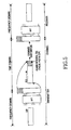
- FIG 1 is a diagram illustrating handover in a conventional Universal Mobile Telecommunication System (UMTS) system.
- the UMTS system includes node-Bs 103a, 103b, 103c, and 103d, one a base station, and radio network controllers (RNCs) 105a and 105b controlling the node-Bs 103a, 103b, 103c, and 103d.
- RNCs radio network controllers
- a UMTS Terrestrial Radio Access Network (UTRAN) 107 composed of the RNCs 105a and 105b is connected to a core network (CN) 109 using an Iu interface.
- CN core network
- Each of the RNCs 105a and 105b selects a node-B 103a, 103b, 103c, or 103d with a higher SNR using an MN 101 and designated channels.
- the MN 101 receives packets from the main node-B 103c. As the MN 101 moves closer to the cell border between the main node-B 103c and the sub node-B 103b, the MN 101 senses a pilot signal from the sub node-B 103b getting stronger. When the pilot signal received from the sub node-B 103b exceeds a predetermined threshold, the MN 101 receives packets from the main node-B 103c and the sub node-B 103b simultaneously.
- the handover algorithm resides in the RNCs 105a and 105b and the MN 101, and is achieved by signaling between the MN 101 and the RNCs 105a and 105b.
- the node-Bs 103a, 103b, 103c, and 103d act as a bridge for transmitting signals from the RNCs 105a and 105b to the MN 101, as the MN 101.
- MNs Since data is modulated/demodulated using IFFT/FFT in an OFDM data transmission/reception scheme, MNs commonly uses two physical layer modules to receive data from different radio access routers (RARs).
- RARs radio access routers
- FIG. 2 is a block diagram illustrating a multiple connection method for supporting mobility of an MN in a conventional OFDM system.
- FIG. 3 is a block diagram illustrating an MN structure for multiple connections.
- an MN 302 maintains connections 410 and 414 with first and second base stations 304 and 306, respectively.
- the connections 410 and 414 include uploading control links 408 and 412, downloading control links 409 and 413, uploading data links 416 and 418, and downloading data links 417 and 419, respectively.
- an MN 900 in order to maintain connections with two base stations, includes an analog processing module 902, an analog-to-digital (A/D) converter 904, a copy module 906, a pair of signal separating circuits 905 and 907, a pair of synchronization loops 908 and 909, and a pair of main digital processing modules 912 and 914.
- A/D analog-to-digital
- An object of the present invention is to substantially solve at least the above problems and/or disadvantages and to provide at least the advantages below. Accordingly, an object of the present invention is to provide a handover method for supporting mobility of a mobile node (MN) by connecting the MN with at least two base stations using one physical layer module.
- MN mobile node
- Another object of the present invention is to provide a handover method for improving resource efficiency by switching an MNthat occupies two control channels and one data channel, between two base stations.
- a further object of the present invention is to provide a handover method for reducing channel noise by using one data channel for switching.
- a further object of the present invention is to provide a handover method for reducing channel occupancy and maximizing space diversity.
- the above objects are achieved by providing a handover method that enables an MN to occupy two control channels and one data channel of at least two base stations simultaneously using one physical layer module.
- a resource allocation method of a multicarrier wireless communication system including a plurality of base stations transmitting data to mobile nodes through an entire system frequency band includes steps of dividing the entire system frequency band into a control band and a data band; and multiplexing the control band to control channels and allocating the multiplexed control channels to the base stations.
- control band is multiplexed using Frequency Division Multiplexing (FDM) or Code Division Multiplexing (CDM).
- FDM Frequency Division Multiplexing
- CDM Code Division Multiplexing
- a data transmission method of a base station in a multicarrier wireless communication system including a plurality of base stations transmitting data to mobile nodes through an entire system frequency band includes the steps of dividing the entire system frequency band into a control band and a data band, and receiving one allocated control channel among control channels generated by multiplexing the control band; and simultaneously transmitting a control signal and data by carrying the control signal on the control channel and the data on the data band.
- a data reception method of a mobile node in a multicarrier wireless communication system including a plurality of base stations transmitting data to mobile nodes through an entire system frequency band includes the steps of receiving signals of the entire system frequency band including a control band multiplexed to control channels for respective base stations and a data band shared by all of the base stations; and selecting a base station to which the mobile node is to be connected according to information included in the control channels for respective base stations of the control band, and receiving data from the selected base station.
- a handover method of a multicarrier wireless communication system including a plurality of base stations transmitting data to mobile nodes through an entire system frequency band includes the steps of receiving signals of the entire system frequency band including a control band multiplexed to control channels for respective base stations and a data band shared by all of the base stations; simultaneously processing the control channels included in the control band; selecting a base station according to the control channel process results; and receiving data from the selected base station via the data channel.
- the control channels include pilot signals.
- Selecting the base station may include the steps of measuring intensity of the pilot signals; and selecting a base station with the pilot signal greatest intensity.
- Selecting the base station may further include steps of comparing intensity of the pilot signals of the base stations with a predetermined threshold; registering base stations, the intensity of pilot signals of which is greater than the predetermined threshold, as handover candidate base stations; determining one of the handover candidate base stations as a handover-target base station if intensity of a pilot signal of a currently connected base station is close to the predetermined threshold; sending a handover initialization request to the currently connected base station and the handover-target base station using a handover decision message; and receiving a duplicate of data transmitted from the currently connected base station and preparing to transmit the duplicate to a mobile node in the handover-target base station if the currently connected base station and the handover-target base station receive the handover decision message.
- a resource allocation method of an OFDM wireless communication system includes the steps of dividing an OFDM symbol duration into a control channel and a data channel; and multiplexing the control channel to a plurality of control subchannels and allocating the multiplexed control subchannels to base stations.
- the control channel is multiplexed using FDM or CDM.
- a data transmission method of a base station in an OFDM wireless communication system includes the steps of dividing an OFDM symbol duration into a control channel and a data channel, and receiving one allocated control subchannel among control subchannels generated by multiplexing the control band; and simultaneously transmitting a control signal and data by carrying the control signal on the allocated control subchannel and the data on the data channel.
- a data reception method of a mobile node in an OFDM wireless communication system includes the steps of receiving an OFDM symbol including a control channel multiplexed to control subchannels for respective base stations and a data channel shared by all of the base stations; and selecting a base station to which the mobile node is to be connected according to information included in the control subchannels for respective base stations of the control channel, and receiving data from the selected base station.
- a mobile node of a multicarrier wireless communication system including a plurality of base stations transmitting data to mobile nodes through an entire system frequency band
- a synchronization module for receiving signals of the entire system frequency band including a control band multiplexed to control channels for respective base stations and a data band shared by all of the base stations and performing timing synchronization on the received signals; a demodulation module for simultaneously demodulating the signals synchronized by the synchronization module; a detection module for detecting the control channels for respective base stations from the signals demodulated by the demodulation module; a selection module for selecting a base station according to the control channels for respective base stations detected by the detection module; and a decoding module for restoring data from the base station selected by the selection module via the data channel.
- the control band is multiplexed using FDM or CDMand the demodulation module is a fast Fourier transformer.
- an OFDM mobile communication system includes a system controller for dividing an OFDM symbol into a control channel and a data channel, multiplexing the control channel to a plurality of control subchannels, and allocating the multiplexed control subchannels to base stations; a plurality of base stations for having allocated the control subchannels and simultaneously transmitting own control signals and data by carrying the own control signals on the control subchannels and the data on the data channel; and a plurality of mobile nodes for receiving an OFDM symbol including a control channel multiplexed to control channels for respective base stations and a data channel shared by all of the base stations and for selecting a base station to be connected according to information included in the control subchannels.
- each base stations includes an inverse fast Fourier transformer for generating an OFDM symbol by modulating the control signal and the data.
- each mobile node includes a physical layer module for simultaneously processing OFDM symbols received from the base stations and the physical layer module is a fast Fourier transformer.
- communication system resources are used more efficiently by using one data channel when switching from movement and by maintaining connections with two handover base stations using two control channels simultaneously.
- FIG. 4 is a schematic block diagram illustrating a structure of a 4 th generation (4G) network based on Mobile IP to which a preferred embodiment of the present invention is applied.
- a core network (CN) 41 includes intermediate routers (IRs) 45a and 45b, which support MN mobility based on an IP (Internet Protocol), and a local gateway (LGW) 43.
- the CN 41 is connected to external networks, such as the Internet, through the LGW 43.
- Each IR 45a and 45b is connected to specific radio access routers (RARs) 47a, 47b and 47c, and provides services to MNs located in its respective service area.
- RARs 47a, 47b and 47c functions like an integrated RNC and BTS (Base station Transceiver Subsystem) in a 3 rd generation (3G) network.
- RNC Radio access routers
- FIG 5 is a conceptual diagram illustrating data transmission and reception in an OFDM system.
- an input signal is converted into a plurality of parallel symbols by serial-to-parallel conversion, and the converted parallel symbols are carried on subcarriers by IFFT.
- the IFFT-processed symbols into which a guard interval (GI) is inserted after the IFFT-processed parallel symbols are multiplexed in a time domain, are then transmitted over a wireless channel.
- GI guard interval
- the receiver the GI is removed from the signal, the signal is removed is restored to the parallel symbols by FFT, and the parallel symbols are restored to the original data by parallel-to-serial conversion.
- FIG. 6 is a conceptual diagram illustrating a data format for handover in an OFDM system according to a preferred embodiment of the present invention.
- bandwidth of a downlink is divided into two parts to realize semi-soft handover according to an embodiment of the present embodiment.
- One part includes dedicated data bands 63a, 63b and 63c for transmitting data
- the other part is a dedicated control band 65 used for a sync channel (SCH), a broadcast channel (BCH), a common pilot channel (CPICH), and a semi-soft-handover control channel (SSHCCH).
- SCH sync channel
- BCH broadcast channel
- CPICH common pilot channel
- SSHCCH semi-soft-handover control channel
- Three RARs transmit data to three MNs .
- the RARs transmit data through the dedicated data bands 63a, 63b and 63c.
- the RARs transmit a control signal including a signal for supporting handover through the dedicated control band 65.
- the dedicated control band 65 is divided and allocated to control channels 65a, 65b and 65c of the three MNs.
- the RARs are distinguished from each other by the unique control channels 65a, 65b and 65c allocated thereto.
- a portion, of the dedicated control band 65, except for its own control channel is zero-padded, and the control channels 65a, 65b and 65c of the RARs are multiplexed and transmitted to the MNs.
- the MNs each receive data from their associated base stations via the dedicated data bands 63a, 63b and 63c by decoding control channels transmitted thereto.
- the dedicated control band 65 can be multiplexed using an FDM technique or a CDM technique.
- the numbers of base stations and MNs in a system according to an embodiment of the present invention are not limited and can be changed according to systems and channel environments.
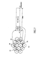
- FIGs. 7 and 8 are conceptual diagrams illustrating control channel allocation of a dedicated control band for handover according to a preferred embodiment of the present invention.
- frequency reuse K 4 to provide an example.
- the dedicated control band is divided into four control channels, and the 4 control channels are allocated one by one to cells 701, 702, 703, and 704 which use independent frequencies.
- Base stations in the cells transmit control signals to MNs by carrying control signals on independent subcarriers, and zero-pad the remaining portion of the dedicated control band. Therefore, each of the MNs can simultaneously analyze sync and broadcast signals transmitted from a plurality of base stations.
- the frequency reuse concept of cellular systems is preferably adopted to present control signal bands from overlapping.
- frequency reuse K 7.
- the dedicated control band is divided into seven control channels, and the seven control channels are allocated one by one to cells 801, 802, 803, 804, 805, 806 and 807, which use independent frequencies.
- FIG. 9 is a conceptual diagram illustrating a procedure in which an MN determines handover using control channels received from two base stations in the system illustrated in FIG 7.
- the MN is moving from a cell#2 702 to a cell#4 704.
- the MN measures and analyzes intensity of pilot signals of the cell#2 702 and the cell#4 704 received via the dedicated control band and determines which cell it will receive data from according to the measured intensity of the pilot signals. Since the intensity of the pilot signal of the cell#4 704 gradually increases, the MN performs handover from an RAR of the cell#2 702 to an RAR of the cell#4 704.
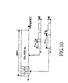
- FIG 10 illustrates a timing synchronization method for simultaneously receiving signals transmitted from different RARs in a handover method according to a preferred embodiment of the present invention.
- a symbol duration and a GI of a control channel are set relatively long compared to the symbol duration and GI of the data channel. It should be noted that lengths of the symbol durations and GIs can be adjusted according to sync performance of the physical layer.
- time periods of the symbol duration and GI of the control channel are set to multiples of time periods of the symbol duration and GI of the data channel. In this example, the time periods of the symbol duration and GI of the control channel are set to two times that of the data channel.
- time periods can be designed differently according to the synchronization methods implemented.
- FIG. 11 is a schematic diagram illustrating a signal transferring procedure in a handover method according to a preferred embodiment of the present invention.
- an MN transmits information on a secondary RAR (SRAR) to a primary RAR (PRAR) in step S1101.
- the PRAR sends a handover initialization request to the SRAR in step S1102.
- the SRAR transmits an ACK message to the PRAR in response to the handover initialization request in step S 1103 and sets up a data channel for handover in step S 1104.
- the PRAR informs the MN that the handover is ready in step S 1105 and transmits a duplicate of a packet received via a CN to the SRAR in step S 1106.
- the PRAR and the SRAR temporarily store the same packet in their own buffers.
- the MN measures intensity of pilot signals received from the PRAR and the SRAR, selects the RAR with greater pilot signal intensity , and informs the PRAR and the SRAR of the selection in step S 1107.
- a signal for handover decision is transmitted from a radio resource controller (RRC) of the MN to RRCs of the PRAR and the SRAR.
- RRC radio resource controller
- the selected SRAR transmits the duplicate of the packet received from the PRAR to the MN in step S 1108.
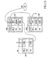
- FIGs. 12 through 15 illustrate a procedure of selecting an RAR in realtime based on pilot signal intensity in a handover method according to a preferred embodiment of the present invention.
- an MN 1205 is moving from an RAR2 1202 to an RAR1 1201 . Since the RAR2 1202 pilot signal is stronger than that of the RAR1 1201 at time P1, the MN 1205 selects the RAR2 1202 as a serving RAR. Once the signal transferring procedure illustrated in FIG. 11 has finished, packets from a CN 1207 are simultaneously transmitted to the RAR1 1201 and the RAR2 1202.
- the MN 1205 informs RAR1 1201 and the RAR2 1202 that the RAR2 1202 has been selected as the serving RAR at time P1.
- the RAR2 1202 receives the selection result message from the MN 1205
- the RAR2 1202 transmits the packets from the CN 1207 to the MN 1205.
- the RAR1 1201 maintains allocated wireless channel resources
- the RAR1 1201 discards the packets buffered to be transmitted to the MN 1205 (refer to FIG 13).
- the MN 1205 when the MN 1205 is getting close to the RAR1 1201, since the RAR1 1201 pilot signal is stronger than that of the pilot signal from the RAR2 1202 at time P2, the MN 1205 selects the RAR1 1201 as the serving RAR.
- the RRC of the MN 1205 informs the RRCs of the RAR1 1201 and the RAR2 1202 that the RAR1 1201 has been selected as the serving RAR at the time P2.
- the RAR1 1201 receives notification from the MN 1205
- the RAR1 1201 transmits the packets from the CN 1207 to the MN 1205.
- the RAR2 1202 receives the selection result message, the RAR2 1202 maintains an idle channel allocated to the MN 1205 and discards the packets from the CN 1207 (refer to FIG 15).
- handover of a mobile node is supported using one physical layer module in an OFDM wireless communication system.
- channel efficiency is improved, and manufacturing costs of mobile nodes are reduced.
- handover is quickly performed without data loss even if only one data channel is used for switching.
- channel occupancy is reduced, and space diversity is maximized.
Abstract
Description
- The present invention relates generally to a mobile communication system, and in particular, to a data transmission and reception method with handover in an Orthogonal Frequency Division Multiplexing (OFDM) communication system.
- OFDM schemes are especially suitable for high-speed data transmission. With the OFDM scheme, serial input data is converted into parallel streams as such numbers of subcarriers which modulated, respectively, such that the symbol duration can be elongated in proportional with the number of subcarriers while maintaining the original date rate.. Since subcarriers are orthogonalized to each other, bandwidth efficiency of the OFDM scheme is excellent compared to the conventional Frequency Division Multiplexing (FDM) scheme. In addition, because the symbol durations are longer in the OFDM scheme, the OFDM scheme is more robust against inter-symbol interference (ISI) than a single-carrier modulating scheme.
- In general, modulation/demodulation of OFDM signals is executed efficiently using Inverse Fast Fourier Transform/Fast Fourier Transform (IFFT/FFT) or Inverse Discrete Cosine Transform/Discrete Cosine Transform (IDCT/DCT). However, since data modulated using IFFT in a modulation process can be restored to its original form by FFT at the reception side, the number of FFT physical layer modules should be equal to the number of base stations to enable simultaneous reception of data from base stations at different locations. In other words, since a mobile node (MN) needs a simultaneous connection to two base stations to perform soft handover, the MN includes two physical layer modules to perform FFT on the data from the two base stations.
- Handovers can be roughly divided into hard handovers and soft handovers.
- Hard handovers perform handover by occupying one resource among wireless channels after cutting off a connection to a previous base station and making a connection to a new base station in a handover process. If the hard handover is used in an OFDM wideband transmission scheme, the handover can be performed using one physical layer module. However, since the currently connected channel is disconnected before handover to the new base station , quality of service (QoS) cannot be guaranteed. Since one data channel and one control channel are occupied in the hard handover, the switching time is long, and since the handover window is designed large to prevent a ping-pong effect between base stations, data transmission uses a lot of powerincreasng interchannel interference (ICI). Further, because of the physical channel disconnection effect, the hard handover is not suitable for realtime services.
- Unlike the hard handover, in the soft handover, an MN can be simultaneously connected to a plurality of base stations if pilot signal size is within a predetermined window. The MN selects data received from a base station of which pilot signal has a higher signal-to-noise ratio (SNR). The soft handover provides better QoS guarantee in low-speed realtime data transmission services such as a voice service. However, since two data channels and two control channels are used to perform the soft handover, interference from use of two data channels may occur. So, the soft handover is suitable for low-speed realtime data such as voice. However, the soft handover has limitations in supporting high-speed data services such as multimedia services, e.g., video on demand (VOD).
- FIG 1 is a diagram illustrating handover in a conventional Universal Mobile Telecommunication System (UMTS) system. Referring to FIG 1, the UMTS system includes node-
Bs Bs RNCs RNCs B MN 101 and designated channels. - In FIG 1, the MN 101 receives packets from the main node-
B 103c. As theMN 101 moves closer to the cell border between the main node-B 103c and the sub node-B 103b, theMN 101 senses a pilot signal from the sub node-B 103b getting stronger. When the pilot signal received from the sub node-B 103b exceeds a predetermined threshold, theMN 101 receives packets from the main node-B 103c and the sub node-B 103b simultaneously. - The handover algorithm resides in the
RNCs MN 101, and is achieved by signaling between theMN 101 and theRNCs Bs RNCs MN 101, as theMN 101. - Since data is modulated/demodulated using IFFT/FFT in an OFDM data transmission/reception scheme, MNs commonly uses two physical layer modules to receive data from different radio access routers (RARs). A system for supporting mobility of an MN using two physical layer modules is disclosed in International Publication No. WO 03/017689.
- FIG. 2 is a block diagram illustrating a multiple connection method for supporting mobility of an MN in a conventional OFDM system. FIG. 3 is a block diagram illustrating an MN structure for multiple connections.
- Referring to FIG. 2, an MN 302 maintains
connections 410 and 414 with first andsecond base stations connections 410 and 414 include uploadingcontrol links control links data links data links MN 900 includes ananalog processing module 902, an analog-to-digital (A/D)converter 904, acopy module 906, a pair ofsignal separating circuits synchronization loops digital processing modules - It is readily apparent that conventional MNs supporting multiple connections, because two physical layer modules are used to support mobility have more complex hardware, increasing manufacturing costs.
- An object of the present invention is to substantially solve at least the above problems and/or disadvantages and to provide at least the advantages below. Accordingly, an object of the present invention is to provide a handover method for supporting mobility of a mobile node (MN) by connecting the MN with at least two base stations using one physical layer module.
- Another object of the present invention is to provide a handover method for improving resource efficiency by switching an MNthat occupies two control channels and one data channel, between two base stations.
- A further object of the present invention is to provide a handover method for reducing channel noise by using one data channel for switching.
- A further object of the present invention is to provide a handover method for reducing channel occupancy and maximizing space diversity.
- The above objects are achieved by providing a handover method that enables an MN to occupy two control channels and one data channel of at least two base stations simultaneously using one physical layer module.
- According to one aspect of the present invention, a resource allocation method of a multicarrier wireless communication system including a plurality of base stations transmitting data to mobile nodes through an entire system frequency band includes steps of dividing the entire system frequency band into a control band and a data band; and multiplexing the control band to control channels and allocating the multiplexed control channels to the base stations.
- It is preferred that the control band is multiplexed using Frequency Division Multiplexing (FDM) or Code Division Multiplexing (CDM).
- According to another aspect of the present invention, a data transmission method of a base station in a multicarrier wireless communication system including a plurality of base stations transmitting data to mobile nodes through an entire system frequency band includes the steps of dividing the entire system frequency band into a control band and a data band, and receiving one allocated control channel among control channels generated by multiplexing the control band; and simultaneously transmitting a control signal and data by carrying the control signal on the control channel and the data on the data band.
- According to another aspect of the present invention, a data reception method of a mobile node in a multicarrier wireless communication system including a plurality of base stations transmitting data to mobile nodes through an entire system frequency band includes the steps of receiving signals of the entire system frequency band including a control band multiplexed to control channels for respective base stations and a data band shared by all of the base stations; and selecting a base station to which the mobile node is to be connected according to information included in the control channels for respective base stations of the control band, and receiving data from the selected base station.
- According to another aspect of the present invention, a handover method of a multicarrier wireless communication system including a plurality of base stations transmitting data to mobile nodes through an entire system frequency band includes the steps of receiving signals of the entire system frequency band including a control band multiplexed to control channels for respective base stations and a data band shared by all of the base stations; simultaneously processing the control channels included in the control band; selecting a base station according to the control channel process results; and receiving data from the selected base station via the data channel. Preferably, the control channels include pilot signals.
- Selecting the base station may include the steps of measuring intensity of the pilot signals; and selecting a base station with the pilot signal greatest intensity.
- Selecting the base station may further include steps of comparing intensity of the pilot signals of the base stations with a predetermined threshold; registering base stations, the intensity of pilot signals of which is greater than the predetermined threshold, as handover candidate base stations; determining one of the handover candidate base stations as a handover-target base station if intensity of a pilot signal of a currently connected base station is close to the predetermined threshold; sending a handover initialization request to the currently connected base station and the handover-target base station using a handover decision message; and receiving a duplicate of data transmitted from the currently connected base station and preparing to transmit the duplicate to a mobile node in the handover-target base station if the currently connected base station and the handover-target base station receive the handover decision message.
- According to one aspect of the present invention, a resource allocation method of an OFDM wireless communication system includes the steps of dividing an OFDM symbol duration into a control channel and a data channel; and multiplexing the control channel to a plurality of control subchannels and allocating the multiplexed control subchannels to base stations. Preferably, the control channel is multiplexed using FDM or CDM.
- According to another aspect of the present invention, a data transmission method of a base station in an OFDM wireless communication system includes the steps of dividing an OFDM symbol duration into a control channel and a data channel, and receiving one allocated control subchannel among control subchannels generated by multiplexing the control band; and simultaneously transmitting a control signal and data by carrying the control signal on the allocated control subchannel and the data on the data channel.
- According to another aspect of the present invention, a data reception method of a mobile node in an OFDM wireless communication system includes the steps of receiving an OFDM symbol including a control channel multiplexed to control subchannels for respective base stations and a data channel shared by all of the base stations; and selecting a base station to which the mobile node is to be connected according to information included in the control subchannels for respective base stations of the control channel, and receiving data from the selected base station.
- According to another aspect of the present invention, a mobile node of a multicarrier wireless communication system including a plurality of base stations transmitting data to mobile nodes through an entire system frequency band includes a synchronization module for receiving signals of the entire system frequency band including a control band multiplexed to control channels for respective base stations and a data band shared by all of the base stations and performing timing synchronization on the received signals; a demodulation module for simultaneously demodulating the signals synchronized by the synchronization module; a detection module for detecting the control channels for respective base stations from the signals demodulated by the demodulation module; a selection module for selecting a base station according to the control channels for respective base stations detected by the detection module; and a decoding module for restoring data from the base station selected by the selection module via the data channel. Preferably, the control band is multiplexed using FDM or CDMand the demodulation module is a fast Fourier transformer.
- According to another aspect of the present invention, an OFDM mobile communication system includes a system controller for dividing an OFDM symbol into a control channel and a data channel, multiplexing the control channel to a plurality of control subchannels, and allocating the multiplexed control subchannels to base stations; a plurality of base stations for having allocated the control subchannels and simultaneously transmitting own control signals and data by carrying the own control signals on the control subchannels and the data on the data channel; and a plurality of mobile nodes for receiving an OFDM symbol including a control channel multiplexed to control channels for respective base stations and a data channel shared by all of the base stations and for selecting a base station to be connected according to information included in the control subchannels. Preferably, each base stations includes an inverse fast Fourier transformer for generating an OFDM symbol by modulating the control signal and the data. It is further preferred that each mobile node includes a physical layer module for simultaneously processing OFDM symbols received from the base stations and the physical layer module is a fast Fourier transformer.
- The above and other objects, features and advantages of the present invention will become more apparent from the following detailed description when taken in conjunction with the accompanying drawings in which:
- FIG 1 is a diagram illustrating handover in a conventional UMTS system;
- FIG 2 is a block diagram illustrating a multiple connection method for supporting MN mobility in a conventional OFDM system; FIG 3 is a block diagram illustrating a MN structure for multiple connections in a conventional OFDM system;
- FIG 4 is a schematic block diagram illustrating a structure of a 4th generation (4G) network based on Mobile IP to which a preferred embodiment of the present invention is applied;
- FIG. 5 is a conceptual diagram illustrating data transmission/reception in an OFDM system;
- FIG. 6 is a conceptual diagram illustrating a data format for handover in an OFDM system according to a preferred embodiment of the present invention;
- FIGs. 7 and 8 are conceptual diagrams illustrating control channel allocation of a dedicated control band for handover according to a preferred embodiment of the present invention;
- FIG 9 is a conceptual diagram illustrating a procedure in which a mobile node determines handover using control channels received from two base stations in the system illustrated in FIG 7;
- FIG. 10 illustrates a timing synchronization method for simultaneously receiving signals transmitted from different RARs in a handover method according to a preferred embodiment of the present invention;
- FIG. 11 is a schematic diagram illustrating a signal transferring procedure in a handover method according to a preferred embodiment of the present invention; and
- FIGs. 12 through 15 illustrate a procedure of selecting an RAR from which data is transmitted in realtime based on intensity of received pilot signals in a handover method according to a preferred embodiment of the present invention.
-
- A preferred embodiment of the present invention will be described herein below with reference to the accompanying drawings. In the following description, well-known functions or constructions are not described in detail since they would obscure the invention in unnecessary detail.
- According to an embodiment of the present invention, communication system resources are used more efficiently by using one data channel when switching from movement and by maintaining connections with two handover base stations using two control channels simultaneously.
- FIG. 4 is a schematic block diagram illustrating a structure of a 4th generation (4G) network based on Mobile IP to which a preferred embodiment of the present invention is applied.
- Referring to FIG. 4, a core network (CN) 41 includes intermediate routers (IRs) 45a and 45b, which support MN mobility based on an IP (Internet Protocol), and a local gateway (LGW) 43. The
CN 41 is connected to external networks, such as the Internet, through theLGW 43. EachIR 45a and 45b is connected to specific radio access routers (RARs) 47a, 47b and 47c, and provides services to MNs located in its respective service area. Each of theRARs - FIG 5 is a conceptual diagram illustrating data transmission and reception in an OFDM system. Referring to FIG. 5, an input signal is converted into a plurality of parallel symbols by serial-to-parallel conversion, and the converted parallel symbols are carried on subcarriers by IFFT. The IFFT-processed symbols, into which a guard interval (GI) is inserted after the IFFT-processed parallel symbols are multiplexed in a time domain, are then transmitted over a wireless channel. In the receiver, the GI is removed from the signal, the signal is removed is restored to the parallel symbols by FFT, and the parallel symbols are restored to the original data by parallel-to-serial conversion.
- FIG. 6 is a conceptual diagram illustrating a data format for handover in an OFDM system according to a preferred embodiment of the present invention.
- Referring to FIG 6, bandwidth of a downlink is divided into two parts to realize semi-soft handover according to an embodiment of the present embodiment. One part includes
dedicated data bands dedicated control band 65 used for a sync channel (SCH), a broadcast channel (BCH), a common pilot channel (CPICH), and a semi-soft-handover control channel (SSHCCH). - Three RARs transmit data to three MNs . In this case, the RARs transmit data through the
dedicated data bands dedicated control band 65. Thededicated control band 65 is divided and allocated to controlchannels - In other words, the RARs are distinguished from each other by the
unique control channels dedicated control band 65, except for its own control channel is zero-padded, and thecontrol channels dedicated data bands - Here, the
dedicated control band 65 can be multiplexed using an FDM technique or a CDM technique. - Although three base stations communicate with three MNs in this example, the numbers of base stations and MNs in a system according to an embodiment of the present invention are not limited and can be changed according to systems and channel environments.
- FIGs. 7 and 8 are conceptual diagrams illustrating control channel allocation of a dedicated control band for handover according to a preferred embodiment of the present invention.
- In FIG 7, frequency reuse K=4 to provide an example., The dedicated control band is divided into four control channels, and the 4 control channels are allocated one by one to
cells - In the example of FIG. 8, frequency reuse K=7. The dedicated control band is divided into seven control channels, and the seven control channels are allocated one by one to
cells - FIG. 9 is a conceptual diagram illustrating a procedure in which an MN determines handover using control channels received from two base stations in the system illustrated in FIG 7.
- Referring to FIG. 9, the MN is moving from a
cell# 2 702 to acell# 4 704. The MN measures and analyzes intensity of pilot signals of thecell# 2 702 and thecell# 4 704 received via the dedicated control band and determines which cell it will receive data from according to the measured intensity of the pilot signals. Since the intensity of the pilot signal of thecell# 4 704 gradually increases, the MN performs handover from an RAR of thecell# 2 702 to an RAR of thecell# 4 704. - FIG 10 illustrates a timing synchronization method for simultaneously receiving signals transmitted from different RARs in a handover method according to a preferred embodiment of the present invention.
- Referring to FIG. 10, in the handover method, a symbol duration and a GI of a control channel are set relatively long compared to the symbol duration and GI of the data channel. It should be noted that lengths of the symbol durations and GIs can be adjusted according to sync performance of the physical layer. To match periodic sync of the two channels, time periods of the symbol duration and GI of the control channel are set to multiples of time periods of the symbol duration and GI of the data channel. In this example, the time periods of the symbol duration and GI of the control channel are set to two times that of the data channel. However, time periods can be designed differently according to the synchronization methods implemented.
- FIG. 11 is a schematic diagram illustrating a signal transferring procedure in a handover method according to a preferred embodiment of the present invention.
- Referring to FIG. 11, an MN transmits information on a secondary RAR (SRAR) to a primary RAR (PRAR) in step S1101. The PRAR sends a handover initialization request to the SRAR in step S1102. The SRAR, transmits an ACK message to the PRAR in response to the handover initialization request in step S 1103 and sets up a data channel for handover in step S 1104. When the PRAR receives the ACK message, the PRAR informs the MN that the handover is ready in step S 1105 and transmits a duplicate of a packet received via a CN to the SRAR in step S 1106. At this point, the PRAR and the SRAR temporarily store the same packet in their own buffers.
- The MN measures intensity of pilot signals received from the PRAR and the SRAR, selects the RAR with greater pilot signal intensity , and informs the PRAR and the SRAR of the selection in step S 1107. At this point, a signal for handover decision is transmitted from a radio resource controller (RRC) of the MN to RRCs of the PRAR and the SRAR. When the handover decision is made, the selected SRAR transmits the duplicate of the packet received from the PRAR to the MN in step S 1108.
- FIGs. 12 through 15 illustrate a procedure of selecting an RAR in realtime based on pilot signal intensity in a handover method according to a preferred embodiment of the present invention.
- Referring to FIG 12, an
MN 1205 is moving from anRAR2 1202 to anRAR1 1201 . Since theRAR2 1202 pilot signal is stronger than that of theRAR1 1201 at time P1, theMN 1205 selects theRAR2 1202 as a serving RAR. Once the signal transferring procedure illustrated in FIG. 11 has finished, packets from aCN 1207 are simultaneously transmitted to theRAR1 1201 and theRAR2 1202. - The
MN 1205 informsRAR1 1201 and theRAR2 1202 that theRAR2 1202 has been selected as the serving RAR at time P1. When theRAR2 1202 receives the selection result message from theMN 1205, theRAR2 1202 transmits the packets from theCN 1207 to theMN 1205. Here, although theRAR1 1201 maintains allocated wireless channel resources, theRAR1 1201 discards the packets buffered to be transmitted to the MN 1205 (refer to FIG 13). - Referring to FIG 14, when the
MN 1205 is getting close to theRAR1 1201, since theRAR1 1201 pilot signal is stronger than that of the pilot signal from theRAR2 1202 at time P2, theMN 1205 selects theRAR1 1201 as the serving RAR. When the serving RAR is changed, the RRC of theMN 1205 informs the RRCs of theRAR1 1201 and theRAR2 1202 that theRAR1 1201 has been selected as the serving RAR at the time P2. When theRAR1 1201 receives notification from theMN 1205, theRAR1 1201 transmits the packets from theCN 1207 to theMN 1205. When theRAR2 1202 receives the selection result message, theRAR2 1202 maintains an idle channel allocated to theMN 1205 and discards the packets from the CN 1207 (refer to FIG 15). - As described above, in the inventive handover methods, handover of a mobile node is supported using one physical layer module in an OFDM wireless communication system. Thus, channel efficiency is improved, and manufacturing costs of mobile nodes are reduced.
- Also, in the inventive handover methods, handover is quickly performed without data loss even if only one data channel is used for switching. Thus, channel occupancy is reduced, and space diversity is maximized.
- While the invention has been shown and described with reference to a certain preferred embodiment thereof, it will be understood by those skilled in the art that various changes in form and details may be made therein without departing from the spirit and scope of the invention as defined by the appended claims.
Claims (31)
- A resource allocation method in a multicarrier wireless communication system including a plurality of base stations transmitting data to mobile nodes through an entire system frequency band, the method comprising:dividing the entire system frequency band into a control band and a data band; andmultiplexing the control band to control channels and allocating the multiplexed control channels to the base stations.
- The method of claim 1, wherein the control band is multiplexed using Frequency Division Multiplexing (FDM).
- The method of claim 1, wherein the control band is multiplexed using Code Division Multiplexing (CDM).
- A data transmission method of a base station in a multicarrier wireless communication system including a plurality of base stations transmitting data to mobile nodes through an entire system frequency band, the method comprising:dividing the entire system frequency band into a control band and a data band, and receiving one allocated control channel among control channels generated by multiplexing the control band; andsimultaneously transmitting a control signal and data by carrying the control signal on the allocated control channel and the data on the data band.
- The method of claim 4, wherein the control band is multiplexed using FDM.
- The method of claim 4, wherein the control band is multiplexed using CDM.
- A data reception method of a mobile node in a multicarrier wireless communication system including a plurality of base stations transmitting data to mobile nodes through an entire system frequency band, the method comprising:receiving signals of the entire system frequency band including a control band multiplexed to control channels for respective base stations and a data band shared by all of the base stations; andselecting a base station to which the mobile node is to be connected according to information included in the control channels for respective base stations of the control band, and receiving data from the selected base station.
- The method of claim 7, wherein the control band is multiplexed using FDM.
- The method of claim 7, wherein the control band is multiplexed using CDM.
- A handover method in a multicarrier wireless communication system including a plurality of base stations transmitting data to mobile nodes through an entire system frequency band, the method comprising the steps of:receiving signals of the entire system frequency band including a control band multiplexed to control channels for respective base stations and a data band shared by all of the base stations;simultaneously processing the control channels included in the control band;selecting a base station according to the control channel process results; andreceiving data from the selected base station via the data channel.
- The method of claim 10, wherein the control channels include pilot signals, respectively.
- The method of claim 11, wherein the step of selecting a base station comprises:measuring intensity of the pilot signals; andselecting a base station with the highest intensity pilot signal.
- The method of claim 12, wherein the step of selecting a base station comprises:comparing intensity of the pilot signals from the base stations with a predetermined threshold;registering the base stations if the intensity is greater than the predetermined threshold, as handover candidate base stations;determining one of the handover candidate base stations as a handover-target base station if intensity of a pilot signal from a currently connected base station is close to the predetermined threshold;sending a handover initialization request to the currently connected base station and the handover-target base station using a handover decision message; andreceiving a duplicate of data transmitted from the currently connected base station and preparing to transmit the duplicate to a mobile node in the handover-target base station if the handover decision message is received.
- A resource allocation method in an OFDM wireless communication system, the method comprising:dividing an OFDM symbol duration into a control channel and a data channel; andmultiplexing the control channel to a plurality of control subchannels and allocating the multiplexed control subchannels to base stations.
- The method of claim 14, wherein the control channel is multiplexed using FDM.
- The method of claim 14, wherein the control channel is multiplexed using CDM.
- A data transmission method of a base station in an OFDM wireless communication system, the method comprising:dividing an OFDM symbol duration into a control channel and a data channel, and receiving one allocated control subchannel among control subchannels generated by multiplexing the control band; andsimultaneously transmitting a control signal and data by carrying the control signal on the allocated control subchannel and the data on the data channel.
- The method of claim 17, wherein the control channel is multiplexed using FDM.
- The method of claim 17, wherein the control channel is multiplexed using CDM.
- A data reception method of a mobile node in an OFDM wireless communication system, the method comprising:receiving an OFDM symbol including a control channel multiplexed to control subchannels for respective base stations and a data channel shared by all of the base stations; andselecting a base station to which the mobile node is to be connected according to information included in the control subchannels for respective base stations of the control channel, and receiving data from the selected base station.
- The method of claim 20, wherein the control channel is multiplexed using FDM.
- The method of claim 20, wherein the control channel is multiplexed using CDM.
- A mobile node in a multicarrier wireless communication system including a plurality of base stations transmitting data to mobile nodes through an entire system frequency band, the mobile node comprising:a synchronization module for receiving signals of the entire system frequency band including a control band multiplexed to control channels for respective base stations and a data band shared by all of the base stations and performing timing synchronization on the received signals;a demodulation module for demodulating the signals synchronized by the synchronization module;a detection module for detecting the control channels for respective base stations from the signals demodulated by the demodulation module;a selection module for selecting a base station according to the control channels for respective base stations detected by the detection module; anda decoding module for restoring data received from the base station selected by the selection module via the data channel.
- The mobile node of claim 23, wherein the control band is multiplexed using FDM.
- The mobile node of claim 23, wherein the control band is multiplexed using CDM.
- The mobile node of claim 23, wherein the demodulation module is a fast Fourier transformer.
- An OFDM mobile communication system comprising:a system controller for dividing an OFDM symbol into a control channel and a data channel, multiplexing the control channel to a plurality of control subchannels, and allocating the multiplexed control subchannels to base stations;a plurality of base stations for receiving allocated control subchannels and simultaneously transmitting their own control signals and data by carrying their own control signals on the control subchannels and the data on the data channel; anda plurality of mobile nodes for receiving an OFDM symbol including a control channel multiplexed to control channels for respective base stations and a data channel shared by all of the base stations and for selecting a base station to which they are to be connected according to information included in the control subchannels.
- The mobile communication system of claim 27, wherein each base station comprises an inverse fast Fourier transformer for generating an OFDM symbol by modulating the control signal and the data.
- The mobile communication system of claim 28, wherein each mobile node includes a physical layer module for simultaneously processing OFDM symbols received from the base stations.
- The mobile communication system of claim 29, wherein the physical layer module is a fast Fourier transformer.
- The mobile communication system of claim 23, wherein the demodulation module simultaneously demonstrates the signals synchronized by the synchronization module.
Applications Claiming Priority (2)
| Application Number | Priority Date | Filing Date | Title |
|---|---|---|---|
| KR1020040045758A KR100744336B1 (en) | 2004-06-18 | 2004-06-18 | Handover method for ofdm-based wireless communication system |
| KR2004045758 | 2004-06-18 |
Publications (3)
| Publication Number | Publication Date |
|---|---|
| EP1608121A2 true EP1608121A2 (en) | 2005-12-21 |
| EP1608121A3 EP1608121A3 (en) | 2006-01-25 |
| EP1608121B1 EP1608121B1 (en) | 2018-05-30 |
Family
ID=34982047
Family Applications (1)
| Application Number | Title | Priority Date | Filing Date |
|---|---|---|---|
| EP05013167.1A Expired - Fee Related EP1608121B1 (en) | 2004-06-18 | 2005-06-17 | Handover for an ofdm wireless communication system |
Country Status (3)
| Country | Link |
|---|---|
| US (1) | US7729313B2 (en) |
| EP (1) | EP1608121B1 (en) |
| KR (1) | KR100744336B1 (en) |
Cited By (4)
| Publication number | Priority date | Publication date | Assignee | Title |
|---|---|---|---|---|
| EP1734684A1 (en) * | 2005-06-15 | 2006-12-20 | Samsung Electronics Co., Ltd. | Multiplexing broadcast and unicast traffic in a multi-carrier wireless network |
| WO2007128704A1 (en) * | 2006-05-10 | 2007-11-15 | Nokia Siemens Networks Gmbh & Co. Kg | Handover in a radio communication system |
| EP2034645A1 (en) * | 2006-06-19 | 2009-03-11 | NTT DoCoMo, Inc. | Transmitting device and communication method |
| EP2037606A1 (en) * | 2006-05-29 | 2009-03-18 | Kyocera Corporation | Wireless base station and method for controlling wireless base station |
Families Citing this family (16)
| Publication number | Priority date | Publication date | Assignee | Title |
|---|---|---|---|---|
| KR100924684B1 (en) | 2006-07-18 | 2009-11-03 | 삼성전자주식회사 | Apparatus and method for communication in broadband wireless communication system |
| JP4519817B2 (en) * | 2006-08-22 | 2010-08-04 | 株式会社エヌ・ティ・ティ・ドコモ | Base station and mobile station |
| JP4777205B2 (en) * | 2006-09-28 | 2011-09-21 | 京セラ株式会社 | Wireless communication system, wireless communication terminal and base station |
| KR100960040B1 (en) * | 2006-10-04 | 2010-05-31 | 삼성전자주식회사 | Relay assisted handover apparatus and method for cellular relay system |
| KR100895101B1 (en) | 2006-10-11 | 2009-04-28 | 한국전자통신연구원 | Apparearus and method for synchronization channel transmission in wireless communication system |
| JP5052280B2 (en) * | 2007-10-01 | 2012-10-17 | 株式会社日立国際電気 | Receiving machine |
| US20090109948A1 (en) * | 2007-10-29 | 2009-04-30 | Infineon Technologies Ag | Radio communication device for generating and transmitting data, radio communication device for receiving and decoding data, method for transmitting data and method for receiving data |
| US8189719B2 (en) | 2008-05-20 | 2012-05-29 | Qualcomm Incorporated | Detection of time-domain sequences sent on a shared control channel |
| DE102010032203A1 (en) * | 2010-07-26 | 2012-01-26 | MAX-PLANCK-Gesellschaft zur Förderung der Wissenschaften e.V. | Method and apparatus for the passive separation and sorting of drops, in particular in a microfluidic system, by using non-optical markers for reactions within the drops |
| JP5660208B2 (en) * | 2011-05-30 | 2015-01-28 | 富士通株式会社 | Data processing method |
| US9198120B2 (en) * | 2012-04-27 | 2015-11-24 | Marvell World Trade Ltd. | Method and apparatus for scanning multiple channels in a wireless network |
| US9838948B2 (en) * | 2014-07-29 | 2017-12-05 | Aruba Networks, Inc. | Deep packet inspection (DPI) aware client steering and load balancing in wireless local area network (WLAN) infrastructure |
| US10868880B2 (en) | 2015-04-30 | 2020-12-15 | V2Com S.A. | Control system with persistent and transient data stores for registration, production and status data for networked devices |
| US10063658B1 (en) * | 2015-04-30 | 2018-08-28 | V2COM, Inc. | Dedicated network platform for data producing devices that emulates distinct data and control channels via bifurcation of single channel environments |
| US10761900B1 (en) | 2015-04-30 | 2020-09-01 | V2Com S.A. | System and method for secure distributed processing across networks of heterogeneous processing nodes |
| CN116546577B (en) * | 2023-07-07 | 2023-09-26 | 中赣通信(集团)有限公司 | Multi-base-station intelligent scheduling method and system for communication switching |
Family Cites Families (15)
| Publication number | Priority date | Publication date | Assignee | Title |
|---|---|---|---|---|
| GB9413481D0 (en) * | 1994-07-05 | 1994-08-24 | British Broadcasting Corp | Improvements to digital transmission systems |
| US6047187A (en) * | 1995-04-07 | 2000-04-04 | Ericsson, Inc. | Stabilized control channel planning using loosely coupled dedicated traffic channels |
| AU766372B2 (en) * | 2000-10-11 | 2003-10-16 | Samsung Electronics Co., Ltd. | Apparatus and method for controlling transmit antenna array for physical downlink shared channel in a mobile communication system |
| KR100735402B1 (en) | 2000-11-07 | 2007-07-04 | 삼성전자주식회사 | Apparatus and Method of Transmission Transmit Format Combination Indicator for Downlink Shared Channel in Asynchronous Mobile Communication System |
| FI20010963A0 (en) * | 2001-05-08 | 2001-05-08 | Nokia Corp | Adaptive Symbol Description in a Mobile System |
| US6980838B2 (en) * | 2001-05-10 | 2005-12-27 | Motorola, Inc. | Control channel to enable a low power mode in a wideband wireless communication system |
| US7042858B1 (en) * | 2002-03-22 | 2006-05-09 | Jianglei Ma | Soft handoff for OFDM |
| US20040081131A1 (en) * | 2002-10-25 | 2004-04-29 | Walton Jay Rod | OFDM communication system with multiple OFDM symbol sizes |
| US7280467B2 (en) * | 2003-01-07 | 2007-10-09 | Qualcomm Incorporated | Pilot transmission schemes for wireless multi-carrier communication systems |
| US7177297B2 (en) * | 2003-05-12 | 2007-02-13 | Qualcomm Incorporated | Fast frequency hopping with a code division multiplexed pilot in an OFDMA system |
| IL156540A0 (en) * | 2003-06-19 | 2004-01-04 | Zion Hada | Ofdma communication system and method |
| KR100950668B1 (en) * | 2003-09-30 | 2010-04-02 | 삼성전자주식회사 | Apparatus and method for transmitting/receiving uplink pilot signal in a communication system using an orthogonal frequency division multiple access scheme |
| US7979072B2 (en) * | 2004-06-04 | 2011-07-12 | Nortel Networks Limited | Method and system for soft handoff in mobile broadband systems |
| US7437164B2 (en) * | 2004-06-08 | 2008-10-14 | Qualcomm Incorporated | Soft handoff for reverse link in a wireless communication system with frequency reuse |
| US7885660B2 (en) * | 2005-08-30 | 2011-02-08 | Samsung Electronics Co., Ltd. | Method and system for performing a soft handoff in an OFDMA wireless network |
-
2004
- 2004-06-18 KR KR1020040045758A patent/KR100744336B1/en not_active IP Right Cessation
-
2005
- 2005-06-17 EP EP05013167.1A patent/EP1608121B1/en not_active Expired - Fee Related
- 2005-06-20 US US11/156,507 patent/US7729313B2/en not_active Expired - Fee Related
Non-Patent Citations (1)
| Title |
|---|
| None |
Cited By (8)
| Publication number | Priority date | Publication date | Assignee | Title |
|---|---|---|---|---|
| EP1734684A1 (en) * | 2005-06-15 | 2006-12-20 | Samsung Electronics Co., Ltd. | Multiplexing broadcast and unicast traffic in a multi-carrier wireless network |
| WO2007128704A1 (en) * | 2006-05-10 | 2007-11-15 | Nokia Siemens Networks Gmbh & Co. Kg | Handover in a radio communication system |
| EP1858282A1 (en) * | 2006-05-10 | 2007-11-21 | Nokia Siemens Networks Gmbh & Co. Kg | Handover in a wiresess communication system |
| US8213384B2 (en) | 2006-05-10 | 2012-07-03 | Nokia Siemens Networks Gmbh & Co. Kg | Handover in a radio communication system |
| EP2037606A1 (en) * | 2006-05-29 | 2009-03-18 | Kyocera Corporation | Wireless base station and method for controlling wireless base station |
| EP2037606A4 (en) * | 2006-05-29 | 2014-02-19 | Kyocera Corp | Wireless base station and method for controlling wireless base station |
| EP2034645A1 (en) * | 2006-06-19 | 2009-03-11 | NTT DoCoMo, Inc. | Transmitting device and communication method |
| EP2034645A4 (en) * | 2006-06-19 | 2014-03-05 | Ntt Docomo Inc | Transmitting device and communication method |
Also Published As
| Publication number | Publication date |
|---|---|
| KR20050120431A (en) | 2005-12-22 |
| EP1608121B1 (en) | 2018-05-30 |
| US7729313B2 (en) | 2010-06-01 |
| EP1608121A3 (en) | 2006-01-25 |
| US20060007888A1 (en) | 2006-01-12 |
| KR100744336B1 (en) | 2007-07-30 |
Similar Documents
| Publication | Publication Date | Title |
|---|---|---|
| US7729313B2 (en) | Handover method for OFDM wireless communication system | |
| US8290067B2 (en) | Spectrum sharing in a wireless communication network | |
| US9867200B2 (en) | Methods and systems for wireless networks with relays | |
| US7782816B2 (en) | Apparatus and method for supporting handover in a broadband wireless access communication system | |
| US8310994B2 (en) | Method for configuring and managing channels in a wireless communication system using AMC channels and diversity channels, transmission/reception apparatus thereof, and system thereof | |
| US7813315B2 (en) | Spectrum sharing in a wireless communication network | |
| US8315229B2 (en) | Methods and apparatus for wireless communication | |
| US7426204B2 (en) | Symbol synchronization method for OFDM-based wireless communication system | |
| KR101614982B1 (en) | The use of first and second preambles in wireless communication signals | |
| KR20140026615A (en) | Systems and methods for uplink signalling | |
| WO2005125250A1 (en) | Soft handoff in ofdma system | |
| JP5059970B2 (en) | Method and system for accelerated wireless communication handover to a target cell | |
| US8811339B2 (en) | Handover schemes for wireless systems | |
| US20050113023A1 (en) | Method of managing communications in a network and the corresponding signal, transmitting device and destination terminal | |
| KR101796802B1 (en) | Multi-carrier operation for wireless systems | |
| KR20120065319A (en) | Apparatus and method for signalling active assignments to a group of wireless stations | |
| KR101085648B1 (en) | Method for transmitting channel quality information in a wireless communication system | |
| CA2767447A1 (en) | Methods and apparatus for wireless communication | |
| KR20050120429A (en) | Frame synchronization method for ofdm-based wireless communication system |
Legal Events
| Date | Code | Title | Description |
|---|---|---|---|
| PUAI | Public reference made under article 153(3) epc to a published international application that has entered the european phase |
Free format text: ORIGINAL CODE: 0009012 |
|
| PUAL | Search report despatched |
Free format text: ORIGINAL CODE: 0009013 |
|
| 17P | Request for examination filed |
Effective date: 20050617 |
|
| AK | Designated contracting states |
Kind code of ref document: A2 Designated state(s): AT BE BG CH CY CZ DE DK EE ES FI FR GB GR HU IE IS IT LI LT LU MC NL PL PT RO SE SI SK TR |
|
| AX | Request for extension of the european patent |
Extension state: AL BA HR LV MK YU |
|
| AK | Designated contracting states |
Kind code of ref document: A3 Designated state(s): AT BE BG CH CY CZ DE DK EE ES FI FR GB GR HU IE IS IT LI LT LU MC NL PL PT RO SE SI SK TR |
|
| AX | Request for extension of the european patent |
Extension state: AL BA HR LV MK YU |
|
| RTI1 | Title (correction) |
Free format text: HANDOVER FOR AN OFDM WIRELESS COMMUNICATION SYSTEM |
|
| AKX | Designation fees paid |
Designated state(s): DE FI FR GB IT SE |
|
| 17Q | First examination report despatched |
Effective date: 20061012 |
|
| RAP1 | Party data changed (applicant data changed or rights of an application transferred) |
Owner name: SAMSUNG ELECTRONICS CO., LTD. Owner name: YONSEI UNIVERSITY |
|
| REG | Reference to a national code |
Ref country code: DE Ref legal event code: R079 Ref document number: 602005054026 Country of ref document: DE Free format text: PREVIOUS MAIN CLASS: H04L0027260000 Ipc: H04W0016120000 |
|
| GRAP | Despatch of communication of intention to grant a patent |
Free format text: ORIGINAL CODE: EPIDOSNIGR1 |
|
| RIC1 | Information provided on ipc code assigned before grant |
Ipc: H04W 36/18 20090101ALI20170210BHEP Ipc: H04W 16/12 20090101AFI20170210BHEP |
|
| INTG | Intention to grant announced |
Effective date: 20170302 |
|
| RIN1 | Information on inventor provided before grant (corrected) |
Inventor name: YUN, SANG-BOH Inventor name: LEE, SANG-HOON Inventor name: CHO, SUNG-HYUN |
|
| GRAJ | Information related to disapproval of communication of intention to grant by the applicant or resumption of examination proceedings by the epo deleted |
Free format text: ORIGINAL CODE: EPIDOSDIGR1 |
|
| INTC | Intention to grant announced (deleted) | ||
| GRAP | Despatch of communication of intention to grant a patent |
Free format text: ORIGINAL CODE: EPIDOSNIGR1 |
|
| INTG | Intention to grant announced |
Effective date: 20171211 |
|
| GRAS | Grant fee paid |
Free format text: ORIGINAL CODE: EPIDOSNIGR3 |
|
| GRAA | (expected) grant |
Free format text: ORIGINAL CODE: 0009210 |
|
| AK | Designated contracting states |
Kind code of ref document: B1 Designated state(s): DE FI FR GB IT SE |
|
| REG | Reference to a national code |
Ref country code: GB Ref legal event code: FG4D |
|
| REG | Reference to a national code |
Ref country code: DE Ref legal event code: R096 Ref document number: 602005054026 Country of ref document: DE |
|
| PG25 | Lapsed in a contracting state [announced via postgrant information from national office to epo] |
Ref country code: FI Free format text: LAPSE BECAUSE OF FAILURE TO SUBMIT A TRANSLATION OF THE DESCRIPTION OR TO PAY THE FEE WITHIN THE PRESCRIBED TIME-LIMIT Effective date: 20180530 Ref country code: SE Free format text: LAPSE BECAUSE OF FAILURE TO SUBMIT A TRANSLATION OF THE DESCRIPTION OR TO PAY THE FEE WITHIN THE PRESCRIBED TIME-LIMIT Effective date: 20180530 |
|
| RIC2 | Information provided on ipc code assigned after grant |
Ipc: H04W 16/12 20090101AFI20170210BHEP Ipc: H04W 36/18 20090101ALI20170210BHEP |
|
| RIC2 | Information provided on ipc code assigned after grant |
Ipc: H04W 16/12 20090101AFI20170210BHEP Ipc: H04W 36/18 20090101ALI20170210BHEP |
|
| PG25 | Lapsed in a contracting state [announced via postgrant information from national office to epo] |
Ref country code: IT Free format text: LAPSE BECAUSE OF FAILURE TO SUBMIT A TRANSLATION OF THE DESCRIPTION OR TO PAY THE FEE WITHIN THE PRESCRIBED TIME-LIMIT Effective date: 20180530 |
|
| REG | Reference to a national code |
Ref country code: DE Ref legal event code: R097 Ref document number: 602005054026 Country of ref document: DE |
|
| PLBE | No opposition filed within time limit |
Free format text: ORIGINAL CODE: 0009261 |
|
| STAA | Information on the status of an ep patent application or granted ep patent |
Free format text: STATUS: NO OPPOSITION FILED WITHIN TIME LIMIT |
|
| PG25 | Lapsed in a contracting state [announced via postgrant information from national office to epo] |
Ref country code: FR Free format text: LAPSE BECAUSE OF NON-PAYMENT OF DUE FEES Effective date: 20180730 |
|
| 26N | No opposition filed |
Effective date: 20190301 |
|
| PGFP | Annual fee paid to national office [announced via postgrant information from national office to epo] |
Ref country code: DE Payment date: 20200520 Year of fee payment: 16 |
|
| PGFP | Annual fee paid to national office [announced via postgrant information from national office to epo] |
Ref country code: GB Payment date: 20200522 Year of fee payment: 16 |
|
| REG | Reference to a national code |
Ref country code: DE Ref legal event code: R119 Ref document number: 602005054026 Country of ref document: DE |
|
| GBPC | Gb: european patent ceased through non-payment of renewal fee |
Effective date: 20210617 |
|
| PG25 | Lapsed in a contracting state [announced via postgrant information from national office to epo] |
Ref country code: GB Free format text: LAPSE BECAUSE OF NON-PAYMENT OF DUE FEES Effective date: 20210617 Ref country code: DE Free format text: LAPSE BECAUSE OF NON-PAYMENT OF DUE FEES Effective date: 20220101 |