EP1610258A1 - RFID communication apparatus with tag position detection means - Google Patents
RFID communication apparatus with tag position detection means Download PDFInfo
- Publication number
- EP1610258A1 EP1610258A1 EP05253882A EP05253882A EP1610258A1 EP 1610258 A1 EP1610258 A1 EP 1610258A1 EP 05253882 A EP05253882 A EP 05253882A EP 05253882 A EP05253882 A EP 05253882A EP 1610258 A1 EP1610258 A1 EP 1610258A1
- Authority
- EP
- European Patent Office
- Prior art keywords
- rfid tag
- antenna
- radio wave
- section
- tag
- Prior art date
- Legal status (The legal status is an assumption and is not a legal conclusion. Google has not performed a legal analysis and makes no representation as to the accuracy of the status listed.)
- Granted
Links
- 230000006854 communication Effects 0.000 title claims description 162
- 238000004891 communication Methods 0.000 title claims description 160
- 238000001514 detection method Methods 0.000 title description 23
- 238000000034 method Methods 0.000 claims description 125
- 230000001276 controlling effect Effects 0.000 claims description 8
- 238000012545 processing Methods 0.000 claims description 6
- 230000002596 correlated effect Effects 0.000 claims description 3
- 230000008569 process Effects 0.000 description 30
- 238000010586 diagram Methods 0.000 description 20
- 230000000875 corresponding effect Effects 0.000 description 6
- 230000008859 change Effects 0.000 description 5
- 238000003384 imaging method Methods 0.000 description 5
- 239000006096 absorbing agent Substances 0.000 description 4
- 238000005259 measurement Methods 0.000 description 4
- 230000003247 decreasing effect Effects 0.000 description 3
- 230000006870 function Effects 0.000 description 3
- 238000012544 monitoring process Methods 0.000 description 3
- 230000003466 anti-cipated effect Effects 0.000 description 2
- 230000005540 biological transmission Effects 0.000 description 2
- 238000005516 engineering process Methods 0.000 description 2
- 238000012986 modification Methods 0.000 description 2
- 230000004048 modification Effects 0.000 description 2
- 230000003044 adaptive effect Effects 0.000 description 1
- 238000003491 array Methods 0.000 description 1
- 230000008901 benefit Effects 0.000 description 1
- 230000007613 environmental effect Effects 0.000 description 1
- 239000012530 fluid Substances 0.000 description 1
Images


Classifications
-
- G—PHYSICS
- G06—COMPUTING; CALCULATING OR COUNTING
- G06K—GRAPHICAL DATA READING; PRESENTATION OF DATA; RECORD CARRIERS; HANDLING RECORD CARRIERS
- G06K17/00—Methods or arrangements for effecting co-operative working between equipments covered by two or more of main groups G06K1/00 - G06K15/00, e.g. automatic card files incorporating conveying and reading operations
-
- G—PHYSICS
- G06—COMPUTING; CALCULATING OR COUNTING
- G06K—GRAPHICAL DATA READING; PRESENTATION OF DATA; RECORD CARRIERS; HANDLING RECORD CARRIERS
- G06K7/00—Methods or arrangements for sensing record carriers, e.g. for reading patterns
- G06K7/0008—General problems related to the reading of electronic memory record carriers, independent of its reading method, e.g. power transfer
-
- G—PHYSICS
- G01—MEASURING; TESTING
- G01S—RADIO DIRECTION-FINDING; RADIO NAVIGATION; DETERMINING DISTANCE OR VELOCITY BY USE OF RADIO WAVES; LOCATING OR PRESENCE-DETECTING BY USE OF THE REFLECTION OR RERADIATION OF RADIO WAVES; ANALOGOUS ARRANGEMENTS USING OTHER WAVES
- G01S3/00—Direction-finders for determining the direction from which infrasonic, sonic, ultrasonic, or electromagnetic waves, or particle emission, not having a directional significance, are being received
- G01S3/02—Direction-finders for determining the direction from which infrasonic, sonic, ultrasonic, or electromagnetic waves, or particle emission, not having a directional significance, are being received using radio waves
- G01S3/74—Multi-channel systems specially adapted for direction-finding, i.e. having a single antenna system capable of giving simultaneous indications of the directions of different signals
-
- G—PHYSICS
- G01—MEASURING; TESTING
- G01S—RADIO DIRECTION-FINDING; RADIO NAVIGATION; DETERMINING DISTANCE OR VELOCITY BY USE OF RADIO WAVES; LOCATING OR PRESENCE-DETECTING BY USE OF THE REFLECTION OR RERADIATION OF RADIO WAVES; ANALOGOUS ARRANGEMENTS USING OTHER WAVES
- G01S5/00—Position-fixing by co-ordinating two or more direction or position line determinations; Position-fixing by co-ordinating two or more distance determinations
- G01S5/02—Position-fixing by co-ordinating two or more direction or position line determinations; Position-fixing by co-ordinating two or more distance determinations using radio waves
- G01S5/04—Position of source determined by a plurality of spaced direction-finders
-
- H04B5/48—
-
- G—PHYSICS
- G01—MEASURING; TESTING
- G01S—RADIO DIRECTION-FINDING; RADIO NAVIGATION; DETERMINING DISTANCE OR VELOCITY BY USE OF RADIO WAVES; LOCATING OR PRESENCE-DETECTING BY USE OF THE REFLECTION OR RERADIATION OF RADIO WAVES; ANALOGOUS ARRANGEMENTS USING OTHER WAVES
- G01S5/00—Position-fixing by co-ordinating two or more direction or position line determinations; Position-fixing by co-ordinating two or more distance determinations
- G01S5/02—Position-fixing by co-ordinating two or more direction or position line determinations; Position-fixing by co-ordinating two or more distance determinations using radio waves
- G01S5/0205—Details
- G01S5/0218—Multipath in signal reception
Definitions
- a frequency band directed to the radio tag includes a 13.56 MHz band, what is called an UHF band of approximately from 800 MHz to 960 MHz, a 2.45 GHz band or the like.
- the radio wave of the UHF band or the 2.45 GHz band of these bands has an advantage that a communication distance can be easily extended longer compared to that of the radio wave of the 13.56 MHz band.
- the radio wave of the UHF band advantageously goes round to shadows more easily compared to the radio wave of the 2.4 GHz. Accordingly, the radio tag and a reader/writer using the radio wave of the UHF band have been progressively developed.
- a distance in which the reader/writer can communicate with the radio tag can be extended from several ten centimeters to about several meters, as compared with a case in which the radio wave of the 13.56 MHz band which is used mainly currently is employed. Therefore, when the radio wave of the UHF band is employed, a communication area as a space region in which the reader/writer can communicate with the radio tag can be extended to a relatively wide range.
- the communication area is widened.
- the number of the radio tags present in the communication area is undesirably increased more than the required number. Accordingly, various methods may be considered for limiting the communication area to a specific space region.
- Fig. 15A shows an example in which beam forming areas are overlapped to control a communication area.
- a plurality of antennas 51 whose directivity is narrowed by a beam forming operation is arranged.
- a space region obtained by overlapping communication areas 52 respectively formed by each of the antennas 51 provided in the reader/writer is set as the communication area by the reader/writer.
- Fig. 15B shows an example in which a communication area is controlled by a beam scanning operation.
- an antenna 51 whose directivity is narrowed is used.
- a predetermined space region is scanned by sequentially changing a directive direction of the antenna 51 within a predetermined range.
- two antennas 51 that scan different space regions respectively are provided.
- a space region obtained by overlapping each of the scanned areas is set as a communication area by the reader/writer.
- the antennas 51 having a high directivity are employed, following merits are obtained as compared with a case in which the antennas 51 having a low directivity are used.
- the communication area 52 covered by the single antenna 51 is narrow, the generation of the collision of the communication can be suppressed and the reliability of the communication can be improved.
- the collision of the communication means that the collision of the communication arises between the antenna 51 and the number of radio tags, since a number of radio tags are present in the communication area 52 corresponding to the certain antenna 51 at the same time. When the collision of the communication arises, the reliability of the communication is lowered.
- the antenna having the low directivity when used, an incommunicable region where the reader/writer cannot communicate with the radio tag is generated within the communication area, which is due to an interference between a direct wave from the reader/writer and a reflected wave which is reflected by a floor surface or a wall surface.
- the antenna 51 having the high directivity when used, such an inconvenience can be eliminated.
- a first problem is that an influence (incommunicable region) due to a multipath arises.
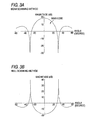
- Fig.16A shows a state that the multipath is generated.
- a reflector 54 exists in the direction of the directivity of the antenna 51
- a beam outputted from the antenna 51 is reflected by the reflector 54.
- the beam is also irradiated to a space region located outside the direction of the directivity of the antenna 51. Accordingly, communication with a radio tag located in a space region other than an estimated communication area is undesirably carried out.
- a radio wave absorber is provided on a surface opposed to the antenna 51 in the communication area in order to prevent the multipath.
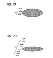
- a second problem is the structural size of the antenna 51 is enlarged.
- the antenna 51 is configured with, for instance, a patch antenna or an array antenna.
- the number of antenna elements 51a provided in the antenna 51 needs to be increased.
- Fig. 17A shows a state of the antenna elements 51a provided in the antenna 51 when the directivity is relatively low
- Fig. 17B shows a state of the antenna elements 51a provided in the antenna 51 when the directivity is relatively high, respectively.
- a third problem is that when a beam scanning operation is carried out, in order to enhance the resolution in a scanning direction, a control of a voltage applied to the antenna elements 51a and the phase thereof becomes complicated.
- Fig. 18 shows a state when the scanning direction of the antenna 51 is changed.
- the antenna elements 51a are respectively provided with voltage controlling phase shifters 51b.
- the voltage applied to the antenna elements 51a respectively corresponding to the voltage controlling phase shifters 51b and the phase of the voltage need to be controlled.
- the voltage controlling phase shifters 51b respectively need to be controlled more finely.
- calculation for the control becomes more complicated, and each of the voltage controlling phase shifters 51b needs to be highly accurate.
- a method may be considered for limiting the communication area by specifying the position of a radio tag performing a communication, and determining whether or not the position of the radio tag is located in a predetermined space region.
- a technique that specifies the position of a GPS receiver by using a GPS is disclosed.
- the GPS receiver measures the incoming time of radio wave from a plurality of GPS satellites to calculate distances between each of the GPS satellites and the GPS receiver. Then, the position is specified based on the calculated distances.
- the above-described techniques may be applied to a specifying operation of the position of the radio tag so as to limit the communication area.
- a complicated circuit for measuring distances to the plurality of the antennas is required.
- timekeeping section for measuring the transmission time of the radio wave is required.
- a synchronization of time with each of the antennas needs to be extremely highly accurately carried out.
- the radio tag basically and preferably has features such as low cost, compact form and low power consumption, it is not preferable to mount such a circuit having high functions on the radio tag.
- a tag communication apparatus that performs a radio communication with the RFID tag through a radio wave, to provide a tag communication apparatus capable of specifying the position of each RFID tag with a simple configuration, a control method of a tag communication apparatus, a computer readable medium for tag communication control and a tag communication control system.
- an apparatus for communicating with an RFID (Radio Frequency Identification) tag through a radio wave said apparatus comprises at least one antenna which receives the radio wave from the RFID tag, a direction estimating section which estimates an incoming direction of the radio wave from the RFID tag in said at least one antenna when the radio wave from the RFID tag is received in said at least one antenna, and a position calculating section which calculates a position of the RFID tag based on the estimated direction.
- RFID Radio Frequency Identification
- a method for controlling an apparatus having at least one antenna which receives a radio wave from an RFID (Radio Frequency Identification) tag to communicate with the RFID tag comprises estimating an incoming direction of the radio wave from the RFID tag in said at least one antenna when the radio wave from the RFID tag is received in said at least one antenna, and calculating a position of the RFID tag based on the estimated direction.
- RFID Radio Frequency Identification
- the tag communication apparatus is provided with at least one antenna. Then, the incoming direction of the radio wave from the RFID tag in each antenna is estimated. In such a way, when the incoming direction of the radio wave is respectively estimated in the at least one antenna, it can be estimated that the RFID tag is located in the vicinity of a point on which the incoming directions of the radio wave converge. Therefore, according to the above-described configuration and the method, on the tag communication apparatus side, the signal received at each antenna is simply processed without adding a special configuration on the RFID tag side. Accordingly, the tag communication apparatus can be provided that can specify the position of the RFID tag capable of performing a communication.
- a direction estimating method referred to as an ESPRIT
- two positions of an array antenna forming one antenna are used so that the incoming directions of the radio wave in the respective positions can be estimated. That is, when the direction estimating method is employed, the above-described configuration and the method according to an embodiment of the present invention can be seemingly realized with a single antenna.
- the tag communication apparatus may further comprises an area determining section which determines whether the calculated position of the RFID tag is within a space region.
- a configuration needs to be taken such as a radio wave absorber is installed in the periphery of the space region.
- a configuration needs to be taken such as a radio wave absorber is installed in the periphery of the space region.
- whether or not the RFID tag is located within the space region is determined on the basis of the position calculated in the position calculating section. Accordingly, an area limitation can be performed without providing the special configuration in an area where the RFID tag may possibly exists and without being influenced by a surrounding environment.
- the tag communication apparatus side since the area limitation is performed by signal processing, change of the area limitation can be easily performed. Accordingly, the tag communication apparatus having a higher flexibility can be provided.
- the tag communication apparatus further comprises a radio wave measuring section which measures an intensity of the radio wave from the RFID tag received in said at least one antenna, and an intensity ratio estimating section which estimates a ratio of the intensity of the radio wave received in said at least one antenna based on a distance between the calculated position of the RFID tag and said at least one antenna, wherein the position calculating section validates the calculated position of the RFID tag based on a ratio of the measured intensity of the radio wave in said at least one antenna and the estimated ratio of the intensity of the radio wave in said at least one antenna.
- the radio wave received from the RFID tag in the antennas respectively may be influenced by the above-described multipath in some cases.
- the position of the RFID tag calculated in the position calculating section may possibly be different from an actual position.
- the multipath is detected by utilizing a fact that the distance between the position of the RFID tag detected on the basis of the estimation of the direction including the multipath and each of antennas is different from the distance between the actual position of the RFID tag and each of antennas. That is, when the estimation of the direction including the multipath is performed, the ratio of the intensity of the actually received radio wave is different from the ratio of the intensity of the received radio wave based on the calculated position.
- the position calculating section detects the difference so that the position calculating section can detect an error of the detection of the position based on the multipath. Accordingly, the position can be more accurately detected.
- said at least one antenna includes a plurality of antenna elements, and the direction estimating section performs signal processing of an output from said at least one antenna so as to execute a scanning operation.
- the signal processing of the output from each of said at least one antenna having the plurality of the antenna elements is performed so as to execute a scanning operation, and the incoming direction of the radio wave is estimated. Accordingly, as compared with, for instance, a configuration in which the scanning operation is performed by physically changing the direction of the antenna, a scanning antenna can be realized with a more simple structure in view of configuration. Thus, a more inexpensive tag communication apparatus can be provided.
- the direction estimating section estimates the incoming direction of the radio wave by null scanning.
- the incoming direction of the radio wave can be detected with a higher resolution than that of a beam scanning method under the same configuration of the antenna and the same conditions.
- the null scanning method is used under the same resolution as that of the beam scanning method, the number of the antenna elements in the antenna can be decreased and the size of the antenna can be decreased.
- a computer readable medium comprises a program including instructions for permitting a computer to perform as the sections in the tag communication apparatus according to an embodiment of the present invention.
- Each of the sections provided in the tag communication apparatus according to an embodiment of the present invention may be realized by a computer.
- the computer is operated as each of the sections.
- each of the sections can be realized by the computer.
- a tag communication control system comprises the tag communication apparatus according to an embodiment of the present invention, and a management section for managing at least one object such as goods, people and a living being correlated with the RFID tag on the basis of a result obtained from the communication with the RFID tag by the tag communication apparatus.
- a system can be easily constituted that can, in managing goods, people and the living being correlated with the RFID tag, recognize positional information thereof.
- the management section includes a photographing section which photographs a space region, and a photographing control section which controls at least one of a photographing direction and a photographing range in the photographing section, and the photographing control section performs the photographing control on the basis of the position of the RFID tag specified by the apparatus.
- the photographing section when it is required to specify a specific goods, a person or a living being in accordance with the result of the communication with the RFID tag, the photographing section performs photographing in direction of the position of the specifiedRFID tag so that a corresponding object may be specified and its evidence can be left.
- the tag communication apparatus As described above, in the tag communication apparatus and the control method for the tag communication apparatus according to the present invention, the incoming direction of the radio wave from the RFID tag in each of the antennas is estimated, and the position of the RFID tag is calculated on the basis of the estimated incoming direction. Accordingly, the tag communication apparatus can be effectively provided in which the position of the RFID tag capable of communication can be specified only by performing a signal processing of signals received by the plurality of the antennas in the tag communication apparatus side without adding any special configurations to the RFID tag side.
- Fig. 1 is a block diagram showing a schematic configuration of an RFID tag communication system according to an embodiment.
- the RFID tag communication system includes one or more RFID tags 1 and a reader/writer (a tag communication apparatus) 2.
- the RFID tag 1 is attached to various kinds of goods, and stores information related to the goods to which the RFID tag is attached, or objects or person related to the goods.
- the RFID tag 1 includes an IC (integrated Circuit) for a radio communication, a storing section and an antenna, etc.
- the usual RFID tag 1 does not have a power source such as a battery, and performs a radio communication with the reader/writer 2 by operating a circuit with an electric power supplied by a radio wave from the reader/writer 2.
- the reader/writer 2 performs the radio communication with each of the RFID tags 1, and reads and writes the information stored in the RFID tag 1. In this embodiment, the reader/writer 2 reads and writes the information stored in the RFID tag 1. However, the reader/writer is not limited thereto, and may be an RFID reader that simply reads the information stored in the RFID tag 1.
- the frequency band of a radio wave transmitted by the reader/writer 2 is what is called a UHF band of approximately from 800 MHz to 960 MHz.
- the radio wave of such a frequency band is employed so that the reader/writer 2 can communicate with the RFID tag 1 located within a range of distance of about several meters.
- the reader/writer 2 includes two or more antennas 3, a position detecting section 4, an area determining section 5, a tag communication control section 6, an area information storing section 7 and an external communication section 8.
- the antennas 3 serve to transmit the radio wave to the RFID tags 1, and receive the radio wave transmitted from the RFID tags 1.
- the antenna 3 is configured with, for instance, a patch antenna, an array antenna or the like, and has a plurality of antenna elements and voltage controlling phase shifters respectively corresponding to the antenna elements.
- the position detecting section 4 is a block for detecting the position of each of the RFID tags 1 on the basis of the receiving state of the radio wave in each of the antennas 3.
- the position detecting section 4 includes a direction estimating section 11, an electric power measuring section (radio wave measuring section) 12, an electric power ratio estimating section (intensity ratio estimating section) 13 and a position calculating section 14.
- the direction estimating section 11 is a block for estimating a direction (angle) in which the RFID tag 1 is located from each of the antennas 3 when the radio wave from the specific RFID tag 1 is received in each of the antennas 3. The detail of a process for estimating the direction will be described below.
- the electric power measuring section 12 is a block for measuring the intensity of the radio wave received in each of the antennas 3 when the radio wave from the specific RFID tag 1 is received in each of the antennas 3. Specifically, the electric power measuring section 12 measures the electric power of the radio wave received in each of the antennas 3.
- the measurement of the intensity of the received radio wave is not limited to the measurement of the electric power. Any of physical quantities may be measured by which the intensity of the radio wave can be measured.
- the position calculating section 14 is a block for calculating the position of the RFID tag 1 on the basis of the direction in which the specific RFID tag 1 is located from each of the antennas 3 and which is estimated in the direction estimating section 11. The detail of a process for calculating the position will be described below.
- the electric power ratio estimating section 13 is a block for estimating the ratio of the intensity of the radio wave from the RFID tag 1 respectively received in the antennas 3 on the basis of the position of the RFID tag 1 calculated in the position calculating section 14.
- the estimated ratio of the intensity of the received radio wave estimated in each of the antennas 3 is compared with the actual ratio of the intensity of the received radio wave that are actually measured by the electric power measuring section 12.
- an error in the detection of the position based on multipath is detected.
- the details of a process for estimating an electric power ratio and the details of a process for detecting the error in the detection of the position will be described below.
- the area determining section 5 is a block for determining whether or not the RFID tag 1 is located within a space region (communication area) on the basis of the position calculated in the position calculating section 14. Area information about what type of space region the communication area belongs to is stored in the area information storing section 7. The area determining section 5 determines whether the position calculated in the position calculating section 14 exists within the communication area specified by the area information. Thus, the area determining section 5 determines whether or not the RFID tag 1 is present in the communication area.
- the tag communication control section 6 is a block for controlling a reading and/or writing operation of information through the antenna 3 about the RFID tag 1 determined to be present in the communication area by the area determining section 5.
- the external communication section 8 is a block for transmitting the information of the RFID tag 1 read in the reader/writer 2 to an external device, or receiving writing information to the RFID tag 1 from the external device.
- the external device is connected for communication to the external communication section 8 by a wired or a wireless system.
- the external device that operates in accordance with reading and writing processes in the RFID tag 1 by the reader/writer 2 may have a configuration in which the reader/writer 2 is incorporated.
- the area information stored in the area information storing section 7 is set depending on an environment in which the reader/writer 2 is installed.
- the area information may be set, for instance, from the external device through the external communication section 8.
- the reader/writer 2 may be provided with a user interface for inputting the area information.
- the position detecting section 4, the area determining section 5, the tag communication control section 6 and the external communication section 8 provided in the above-described reader/writer 2 can be realized by a computing unit such as a CPU executing a program stored in storing devices such as a ROM (Read Only Memory) or a RAM. Accordingly, a computer having the unit and the storing device simply reads a computer readable medium on which the program is recorded, and executes the program so that various kinds of functions and various kinds of processes of the position detecting section 4, the area determining section 5, the tag communication control section 6 and the external communication section 8 can be realized. Further, the program may be recorded on a removable computer readable medium, so that the various kinds of functions and the various kinds of processes can be realized on an arbitrary computer.
- the computer readable medium a memory that is not shown in the drawings to perform a process on a computer, for instance, the ROM may be used as a program medium. Further, a program medium may be employed that can be read by inserting a computer readable medium into a program reading device as an external storing device that is not shown in the drawings.
- the stored program preferably has a configuration accessed and executed by a microprocessor. Further, the program is executed preferably in a way that the program is read, the read program is downloaded in the program storing area of a microcomputer, and then the program is executed.
- the program to be downloaded is previously stored in a main apparatus.
- a computer readable medium When a system configuration is capable of connecting to a communication network including an Internet, a computer readable medium preferably carries the program in a fluid manner such as downloading the program from the communication network.
- a program for downloading is preferably previously stored in the main apparatus or installed from a different computer readable medium.
- Fig. 2A is a diagram conceptually showing a way of estimating the direction on the basis of the outputs of antenna elements 3a provided in the antenna 3.
- the direction estimating section 11 applies different weights Wn to the outputs of the antenna elements 3a respectively to detect the intensity of the radio wave in a specific direction on the basis of sum of signals.
- the combinations of the weights Wn to the outputs of the antenna elements 3a are changed so that a scanning operation is realized by a signal process.
- Fig. 2B and Fig. 2C show the change of directivity (main lobe) when the combinations of the weights Wn are changed.
- a technique that the scanning operation is realized by the signal process on the basis of the outputs from the antenna having the plurality of the antenna elements, and the incoming direction of the radio wave is estimated is called a DOA (Direction Of Arrival).
- DOA Direction Of Arrival
- a Beamformer method, a Capon method, an LP (Linear Prediction) method, a Min-Norm method, a MUSIC method and an ESPRIT method, etc. may be exemplified.
- the Beamformer method and the Capon method of these methods are classified into a direction estimating method by a beam scanning method.
- the LP method, the Min-Norm method, the MUSIC method and the ESPRIT method are classified into a direction estimating method by a null scanning method.
- the beam scanning method is a method for estimating the incoming direction of the radio wave on the basis of the highness of the electric power of the received radio wave.
- Fig. 3A is a graph showing an example of the directivity in the beam scanning method.
- the thickness of the main lobe affects an angular resolution. Accordingly, to enhance the resolution, the width of the beam needs to be reduced by, for instance, increasing the number of the antenna elements 3a in the antenna 3.
- the null scanning method is a method for estimating the incoming direction of the radio wave on the basis of the lowness of the electric power of the received radio wave.
- Fig. 3B is a graph showing an example of the directivity in the null scanning method.
- the null scanning method has a merit that a highly accurate direction resolution can be obtained even with a small number of arrays (the number of the antenna elements).
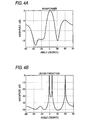
- Fig. 4A is a graph showing a result of the estimated direction when the Beamformer method is used as the example of the beam scanning method.
- Fig. 4B is a graph showing a result of the estimated direction when the LP method is used as the example of the null scanning method.
- a horizontal line shows an angle corresponding to a direction
- a vertical line shows intensity corresponding to the angle.
- ⁇ wavelength of incoming wave
- an SNR Signal to Noise Ratio
- the resolution is relatively low so that the detection of the incoming wave from 0° and 10° is overlapped and unclear.
- the three incoming wave are apparently detected with fine accuracy.
- the direction of the incoming wave can be detected with a higher resolution than that of the beam scanning method under the same configuration of the antenna and the same conditions, compared to the beam scanning method.
- the LP method by the null scanning method is employed under the same resolution, the number of antenna elements in the antenna can be reduced more than that of the beam scanning method.
- the size of the antenna can be decreased more than that of the beam scanning method.
- Fig. 5A and Fig. 5B respectively show the configuration of the antenna 3 in the beam scanning method and the configuration of the antenna 3 in the null scanning method under the same resolution.
- the direction estimating section 11 estimates the direction by using the LP method by the null scanning method.
- the method of the DOA employed in the direction estimating section 11 is not limited to the LP method. Other method of the null scanning method may be employed. Further, the direction estimating section 11 may employ the beam scanning method depending on a permissible size of the antenna 3 or a required resolution.
- Fig. 6 is a diagram for explaining a method for estimating the position of the RFID tag 1 on the basis of the estimation of the incoming directions of the radio wave by two antennas 3X and 3Y.
- the direction estimating section 11 estimates that an angle showing the direction in which the RFID tag 1 is arranged is ⁇ 1 on the basis of a receiving state in the antenna 3X. Further, the direction estimating section 11 estimates in the same manner that an angle showing the direction in which the RFID tag 1 is arranged is ⁇ 2 on the basis of a receiving state in the antenna 3Y.
- the position calculating section 14 calculates the position of the RFID tag 1 on the basis of the above-described ⁇ 1 and ⁇ 2, and the positions P1 and P2 in which the antenna 3X and the antenna 3Y are arranged. Specifically, an intersecting point of a straight line directed to the direction at the angle of ⁇ 1 from the antenna 3X and a straight line directed to the direction at the angle of ⁇ 2 from the antenna 3Y is calculated as the position of the RFID tag 1.
- a method of detecting an error in the position detection based on multipath in the position calculating section 14 will be described.
- the RFID tag 1 is arranged in a position shown as P11.
- the two antennas 3X and 3Y directly receive the radio wave from the RFID tag 1, the position P11 can be precisely detected.
- the position P11 can be precisely detected.
- Fig. 7 a phenomenon in which the position is erroneously detected due to the multipath.
- the direction estimating section 11 recognizes the incoming direction of the radio wave in the antenna 3Y as a direction different from the direction in which the RFID tag 1 is actually located. As a result, the position calculating section 14 calculates the position where the RFID tag 1 locates as a position P12 different from the actual position.
- the position calculating section 14 compares the estimated ratio of the intensity of the radio wave respectively received in the antennas 3 that is estimated by the electric power ratio estimating section 13, with the actual ratio of the intensity of the received radio wave that is actually measured by the electric power measuring section 12, so as to detect the error in the detection of the position.
- an electric power PX of the received radio wave in the antenna 3X and an electric power PY of the received radio wave in the antenna 3Y are firstly measured.
- the electric power ratio estimating section 13 recognizes a distance from the antenna 3X to the RFID tag 1 and a distance from the antenna 3Y to the RFID tag 1 on the basis of the position of the RFID tag 1 calculated in the position calculating section 14. Then, the electric power ratio estimating section 13 calculates the ratio of an estimated electric power PX' of the received radio wave in the antenna 3X and an estimated electric power PY' of the received radio wave in the antenna 3Y on the basis of these distances.
- the position calculating section 14 calculates a difference between PX/PY and PX'/PY'.
- the position calculating section 14 determines that the detection of the position is an erroneous detection due to the multipath. That is, the position calculating section 14 detects the error in the detection of the position by using a below-described principle. Initially, distances to each of the antennas 3 from the position of the RFID tag 1 detected on the basis of the estimation of the direction including the multipath are respectively different from distances to the antennas 3 from the actual position of the RFID tag 1.
- the ratio of the actual electric power of the received radio wave is different from the ratio of the electric power of the received radio wave based on the calculated position.
- the position calculating section 14 can detect the error in the detection of the position based on the multipath in accordance with the above-described processes.
- Fig. 8 is a diagram for explaining the area determining process.
- the area determining section 5 obtains the information of the calculated position of the RFID tag 1 from the position calculating section 14, and reads the area information related to the communication area stored in the area information storing section 7.
- the communication area is a space region shown by 21 and the calculated position of the RFID tag 1 is a position P21, since the position P21 is located within the communication area 21, the RFID tag 1 is recognized to be present within the communication area.
- the calculated position of the RFID tag 1 is a position P22, since the position P22 is located outside the communication area 21, the RFID tag 1 is recognized to exist outside the communication area.
- the positional information of the obstacle may be included in the area information stored in the area information storing section 7.
- the position calculated by the position calculating section 14 is located within the communication area, if it is determined that the calculated position is in the space region in which the obstacle exists, the position may be recognized to be erroneously detected.
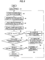
- step 1 an initial setting is carried out.
- the initial setting the area information stored in the area information storing section 7 is set, and the value Ps used for detecting the erroneous detection due to the multipath in the position calculating section 14 is set.
- the initial setting process may be carried out from the external device through, for instance, the external communication section 8 as described above, or may be inputted by a user interface provided in the reader/writer 2 for inputting the area information.
- the initial setting is performed, for instance, when the reader/writer 2 is initially installed. Once the initial setting is performed, the initial setting is not carried out upon start using (turning on a power) the reader/writer 2 as long as change in the initial setting is required thereafter, and a next process from S2 is started.
- the antennas 3 respectively wait for receiving the radio wave from the RFID tag 1. Then, in S2, when each of the antennas 3 receives the radio wave from the RFID tag 1, the direction estimating section 11 performs a process for estimating the angles of the incoming radio wave in the antennas 3 respectively. When two antennas 3 are provided, the direction estimating section 11 respectively calculates incoming angles ⁇ 1 and ⁇ 2 of the radio wave in the antennas 3.
- the electric power measuring section 12 measures the electric power of the radio wave from the RFID tag 1 respectively received in the antennas 3.
- the electric power measuring section 12 measures an electric power PX and PY of the received radio wave in the two antennas 3 respectively.
- the position calculating section 14 calculates the position of the RFID tag 1 on the basis of the incoming angles in the antennas respectively which are calculated in the direction estimating section 11 in the S2.
- the position of the RFID tag 1 is calculated on the basis of the incoming angles ⁇ 1 and ⁇ 2 of the radio wave in the antennas 3 respectively.
- the electric power ratio estimating section 13 performs a process for estimating the ratio (power ratio) of the intensity of the radio wave received from the RFID tag 1 in the antennas 3 respectively on the basis of the position of the RFID tag 1 calculated by the position calculating section 14 in the S4.
- the ratio PX'/PY' of the intensity of the received radio wave is estimated.
- the position calculating section 14 performs a process for detecting an error in the detection of the position based on the multipath. Specifically, the position calculating section 14 calculates a difference between PX/PY and PX' /PY'. When the absolute value of the difference is larger than a value Ps, the position calculating section 14 determines that the detection of the position is an erroneous detection due to the multipath.
- the area determining section 5 determines whether or not the position calculated by the position calculating section 14 is located within the communication area. In the S8, in the case of No, that is, when it is determined that the position calculated by the position calculating section 14 is located outside the communication area, it is determined that the RFID tag 1 is located outside the communication area (S9). Thus, a communication with the RFID tag 1 is not performed, and the process returns to the S2.
- the area determining section 5 determines whether an obstacle is not present in the position calculated in the position calculating section 14 in S10.
- NO in the S10 that is, when it is determined that the obstacle is present in the position calculated in the position calculating section 14, it is determined that the calculated position is erroneously measured (S11).
- the two antennas 3 are provided to calculate the position of the RFID tag 1.
- three or more antennas 3 may be provided and the position of the RFID tag 1 may be calculated on the basis of the estimation of the incoming directions of the radio wave in all the antennas 3.
- the positions of the RFID tag 1 is specified on the basis of positions calculated with each of the combinations. More specifically, the position of the RFID tag 1 is specified by majority voting from the positions calculated with each of the combinations.
- Fig. 10 is a diagram for explaining a method for calculating the position when four antennas 3X, 3Y, 3W and 3Z are provided. In this case, six positions are calculated by the antennas 3X and 3Y, the antennas 3X and 3W, the antennas 3X and 3Z, the antennas 3Y and 3W, the antennas 3Y and 3Z and the antennas 3W and 3Z.
- the position calculated by the antennas 3X and 3Y, the antennas 3X and 3Z and the antennas 3Y and 3Z is referred as P31.
- the position calculated by the antennas 3Y and 3W is referred as P32.
- the position calculated by the antennas 3X and 3W is referred as P33.
- the position calculated by the antennas 3W and the 3Z is referred as P34.
- the position calculating section 14 calculates the position P31 as the position of the RFID tag 1. That is, the position P32, the position P33 and the position P34 are recognized as the erroneous detection due to the influence of the multipath.
- the position P32, the position P33 and the position P34 are detected because the direction of the RFID tag 1 in the antenna 3W is erroneously estimated due to the multipath.
- the three or more antennas 3 are provided so that an error in the detection of the position due to the multipath can be detected. Accordingly, the influence of the multipath that is not detected, for instance, by comparing the power ratio, can be detected by the detection of the position. Therefore, the position can be calculated more accurately.
- Fig. 11 shows an example in which the RFID tag communication system is applied to a system for inspecting and checking distributed goods in a system where the distribution of goods is performed.
- a plurality of goods to which the RFID tags 1 are attached are accommodated in a cargo 41 carried by a forklift.
- the forklift passes a communication area 21 so that the reader/writer 2 perform communication with the RFID tags 1 respectively.
- the distribution of each of the goods can be controlled.
- the system is the RFID tag communication system in which the communication area 21 is not clearly set, and when the RFID tag 1 that does not need to be communicated with is located at a position relatively near the reader/writer 2, a communication with the RFID tag 1 is likewise performed. Accordingly, the communication area 21 needs to be clearly set. However, in most of the cases, a radio wave absorber is hardly installed in an environmental point of view. As compared therewith, in the RFID tag communication system according to this embodiment, since the communication area 21 is set by the process in the reader/writer 2, there is no need to install something for an environment. That is, the RFID tag communication system according to this embodiment can be easily set irrespective of an environment in which the RFID tag communication system is installed.
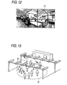
- Fig. 12 shows an example in which the RFID tag communication system according to the embodiment is applied to a system for monitoring the robbery of goods in a shop or the like.
- the RFID tags are attached to CDs or the like as the goods, and a system is employed in which a gate provided with a reader/writer communicating with the RFID tags is provided in an entrance of the shop.
- the gates need to be provided in all the entrances to the shop.
- the shop is installed in an open space as shown in Fig. 12, the system is hardly applied.
- the communication area 21 is set to an area where the entire part of the shop is covered as shown in Fig. 12.
- the gates do not need to be provided. Accordingly, the RFID tag communication system can be flexibly constructed in various kinds of environments of the shops.
- the entire part of the shop can be set in the communication area 21, not only the robbery of the goods can be monitored, but also where a certain goods is located can be detected.
- Fig. 13 shows an example in which the RFID tag communication system is applied to a place requiring a ticket wicket such as a station or a movie theater.
- a system for examining tickets using the RFID tag has been spread.
- a reader/writer is provided in a gate to examine tickets.
- the entire part of a passage for examining the tickets is set to the communication area 21. Accordingly, the tickets can be examined without providing the gate.
- the RFID tag 1 may be incorporated in a portable telephone possessed by a user.
- a monitor camera is provided in the above-described RFID tag communication system.
- the system when there is a user who is not permitted to pass, in accordance with a communication result with the RFID tag 1, there may be a need to specify the who is not permitted to pass.
- the position of the user who is not permitted to pass which is specified by the reader/writer 2 is photographed by the monitor camera, so that the user who is not permitted to pass can be specified and an evidence thereof can be left.
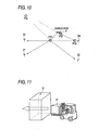
- Fig. 14 shows a structural example in which a monitor camera (a photographing section) 43 is provided in the RFID tag communication system.
- the monitor camera 43 includes a communication section 44, a direction control section (a photographing control section) 45, a zoom control section (a photographing control section) 46 and an imaging section 47.
- the communication section 44 serves to communicate with a reader/writer 2 and obtains information related to a position to be photographed from the reader/writer 2.
- the direction control section 45 controls a changing operation of a photographing direction by the imaging section 47 on the basis of the information related to the position to be photographed that is received by the communication section 44.
- the zoom control section 46 controls a zooming operation in the imaging section 47 on the basis of a distance between the position to be photographed that is received by the communication section 44 and the imaging section 47. The user who is not permitted to pass can be properly photographed by the above-described configuration.
- the tag communication apparatus and the tag communication system having the tag communication apparatus according to the present invention may be applied to the uses for various objects, such as the above-described system for inspecting and checking the goods to be distributed, the system for monitoring the robbery of the goods in the shop or the like, a wicket system installed in the place requiring a wicket for examining tickets such as the station or the movie theater, etc.
Abstract
Description
- This application claims foreign priority based on Japanese Patent application No. 2004-184094, filed June 22, 2004, the contents of which is incorporated herein by reference in its entirety.
- 1. The present invention relates to an apparatus for communicating with an RFID (Radio Frequency Identification) tag through a radio wave (hereinafter, referred to as tag communication apparatus), a control method for a tag communication apparatus, a computer readable medium for tag communication control and a tag communication control system.
- 2. In recent years, the use of an RFID (Radio Frequency Identification) tag (radio rag) has been progressively spread. The radio tag is anticipated especially in a field of physical distribution as an alternative of a bar code. Thus, the radio tag is expected to be widely used in near future.
-
- Currently, a frequency band directed to the radio tag includes a 13.56 MHz band, what is called an UHF band of approximately from 800 MHz to 960 MHz, a 2.45 GHz band or the like. The radio wave of the UHF band or the 2.45 GHz band of these bands has an advantage that a communication distance can be easily extended longer compared to that of the radio wave of the 13.56 MHz band. Further, the radio wave of the UHF band advantageously goes round to shadows more easily compared to the radio wave of the 2.4 GHz. Accordingly, the radio tag and a reader/writer using the radio wave of the UHF band have been progressively developed.
- When the radio wave of the UHF band is employed, a distance in which the reader/writer can communicate with the radio tag can be extended from several ten centimeters to about several meters, as compared with a case in which the radio wave of the 13.56 MHz band which is used mainly currently is employed. Therefore, when the radio wave of the UHF band is employed, a communication area as a space region in which the reader/writer can communicate with the radio tag can be extended to a relatively wide range. (Refer to JP-A-2002-198722, JP-A-9-5431, "View of GPS technology", Journal of Institute of Electronics, Information, and Communication Engineers, B, Vol.J84-B, No.12, pp.2082-2091, December 2001, "Highly accurate position measuring technique using portable telephone that can use positional information service even indoors" http://www.hitachi.co.jp/Sp/TJ/2001/hrnjan01/hrn0111 j.htm, "Adaptive signal processing by array antenna", Chapter 9, High resolution estimation of incoming direction by array antenna, Nobuyoshi Kikuma, Science Press, Inc., issued on November 25, 1998.)
- As described above, when the distance in which the reader/writer can communicate with the radio tag is set to about several meters, the communication area is widened. Thus, the number of the radio tags present in the communication area is undesirably increased more than the required number. Accordingly, various methods may be considered for limiting the communication area to a specific space region.
- Fig. 15A shows an example in which beam forming areas are overlapped to control a communication area. In this example, a plurality of
antennas 51 whose directivity is narrowed by a beam forming operation is arranged. Thus, a space region obtained by overlappingcommunication areas 52 respectively formed by each of theantennas 51 provided in the reader/writer is set as the communication area by the reader/writer. - Fig. 15B shows an example in which a communication area is controlled by a beam scanning operation. In this example, an
antenna 51 whose directivity is narrowed is used. A predetermined space region is scanned by sequentially changing a directive direction of theantenna 51 within a predetermined range. Further, in this example, twoantennas 51 that scan different space regions respectively are provided. A space region obtained by overlapping each of the scanned areas is set as a communication area by the reader/writer. - In the above-described two examples, since the
antennas 51 having a high directivity are employed, following merits are obtained as compared with a case in which theantennas 51 having a low directivity are used. Firstly, since thecommunication area 52 covered by thesingle antenna 51 is narrow, the generation of the collision of the communication can be suppressed and the reliability of the communication can be improved. The collision of the communication means that the collision of the communication arises between theantenna 51 and the number of radio tags, since a number of radio tags are present in thecommunication area 52 corresponding to thecertain antenna 51 at the same time. When the collision of the communication arises, the reliability of the communication is lowered. - Further, when the antenna having the low directivity is used, an incommunicable region where the reader/writer cannot communicate with the radio tag is generated within the communication area, which is due to an interference between a direct wave from the reader/writer and a reflected wave which is reflected by a floor surface or a wall surface. However, when the
antenna 51 having the high directivity is used, such an inconvenience can be eliminated. - However, the above-described examples have the following problems. A first problem is that an influence (incommunicable region) due to a multipath arises. Fig.16A shows a state that the multipath is generated. When a
reflector 54 exists in the direction of the directivity of theantenna 51, a beam outputted from theantenna 51 is reflected by thereflector 54. Thus, the beam is also irradiated to a space region located outside the direction of the directivity of theantenna 51. Accordingly, communication with a radio tag located in a space region other than an estimated communication area is undesirably carried out. - In order to prevent this area distortion, for every place in which the reader/writer is installed, an environment where the reader/writer is installed needs to be tuned, or a radio wave cut-off configuration needs to be provided so as not to be influenced by the multipath. For instance, as shown in Fig. 16B, a radio wave absorber is provided on a surface opposed to the
antenna 51 in the communication area in order to prevent the multipath. - Further, a second problem is the structural size of the
antenna 51 is enlarged. When the communication area is controlled by overlapping the beam forming areas or performing the beam scanning operation as in the above-described examples, the directivity of theantenna 51 needs to be relatively enhanced. Theantenna 51 is configured with, for instance, a patch antenna or an array antenna. In order to strengthen the directivity, the number ofantenna elements 51a provided in theantenna 51 needs to be increased. Fig. 17A shows a state of theantenna elements 51a provided in theantenna 51 when the directivity is relatively low, and Fig. 17B shows a state of theantenna elements 51a provided in theantenna 51 when the directivity is relatively high, respectively. - Further, a third problem is that when a beam scanning operation is carried out, in order to enhance the resolution in a scanning direction, a control of a voltage applied to the
antenna elements 51a and the phase thereof becomes complicated. Fig. 18 shows a state when the scanning direction of theantenna 51 is changed. As shown in Fig. 18, theantenna elements 51a are respectively provided with voltage controllingphase shifters 51b. In order to change the scanning direction, the voltage applied to theantenna elements 51a respectively corresponding to the voltage controllingphase shifters 51b and the phase of the voltage need to be controlled. Here, in order to enhance the resolution in changing the scanning direction, the voltage controllingphase shifters 51b respectively need to be controlled more finely. Thus, calculation for the control becomes more complicated, and each of the voltage controllingphase shifters 51b needs to be highly accurate. - On the other hand, a method may be considered for limiting the communication area by specifying the position of a radio tag performing a communication, and determining whether or not the position of the radio tag is located in a predetermined space region. Here, in "View of GPS technology", Journal of Institute of Electronics, Information, and Communication Engineers, B, Vol.J84-B, No.12, pp.2082-2091, December 2001, a technique that specifies the position of a GPS receiver by using a GPS is disclosed. In this technique, the GPS receiver measures the incoming time of radio wave from a plurality of GPS satellites to calculate distances between each of the GPS satellites and the GPS receiver. Then, the position is specified based on the calculated distances.
- Further, in "Highly accurate position measuring technique using portable telephone that can use positional information service even indoors" http://www.hitachi.co.jp/Sp/TJ/2001/hrnjan01/hrn0111 j.htm, a technique is disclosed that the same system as that of the position detection by the GPS is applied to a portable telephone to specify the position of the portable telephone. In this technique, a base station in a portable telephone network plays the role of the GPS satellite in GPS to measure the position.
- The above-described techniques may be applied to a specifying operation of the position of the radio tag so as to limit the communication area. However, in this case, following problems arise. Initially, in the radio tag side, for instance, a complicated circuit for measuring distances to the plurality of the antennas is required. For instance, to measure the distance between the antenna and the radio tag, timekeeping section for measuring the transmission time of the radio wave is required. To measure the transmission time of the radio wave located within a distance of about several meters or smaller, extremely highly accurate timekeeping operation needs to be carried out. Further, a synchronization of time with each of the antennas needs to be extremely highly accurately carried out. Since the radio tag basically and preferably has features such as low cost, compact form and low power consumption, it is not preferable to mount such a circuit having high functions on the radio tag.
- Considering the above-described problems, it is an object of the present invention, in a tag communication apparatus that performs a radio communication with the RFID tag through a radio wave, to provide a tag communication apparatus capable of specifying the position of each RFID tag with a simple configuration, a control method of a tag communication apparatus, a computer readable medium for tag communication control and a tag communication control system.
- In order to solve the above-described problems, according to an embodiment of the invention, an apparatus for communicating with an RFID (Radio Frequency Identification) tag through a radio wave, said apparatus comprises at least one antenna which receives the radio wave from the RFID tag, a direction estimating section which estimates an incoming direction of the radio wave from the RFID tag in said at least one antenna when the radio wave from the RFID tag is received in said at least one antenna, and a position calculating section which calculates a position of the RFID tag based on the estimated direction.
- Further, in order to solve the above-described problems, according to an embodiment of the invention, a method for controlling an apparatus having at least one antenna which receives a radio wave from an RFID (Radio Frequency Identification) tag to communicate with the RFID tag, said method comprises estimating an incoming direction of the radio wave from the RFID tag in said at least one antenna when the radio wave from the RFID tag is received in said at least one antenna, and calculating a position of the RFID tag based on the estimated direction.
- In the above-described configuration and the method, firstly, the tag communication apparatus is provided with at least one antenna. Then, the incoming direction of the radio wave from the RFID tag in each antenna is estimated. In such a way, when the incoming direction of the radio wave is respectively estimated in the at least one antenna, it can be estimated that the RFID tag is located in the vicinity of a point on which the incoming directions of the radio wave converge. Therefore, according to the above-described configuration and the method, on the tag communication apparatus side, the signal received at each antenna is simply processed without adding a special configuration on the RFID tag side. Accordingly, the tag communication apparatus can be provided that can specify the position of the RFID tag capable of performing a communication.
- According to a direction estimating method referred to as an ESPRIT, two positions of an array antenna forming one antenna are used so that the incoming directions of the radio wave in the respective positions can be estimated. That is, when the direction estimating method is employed, the above-described configuration and the method according to an embodiment of the present invention can be seemingly realized with a single antenna.
- Further, the tag communication apparatus according to an embodiment of the present invention may further comprises an area determining section which determines whether the calculated position of the RFID tag is within a space region.
- Usually, in order to communicate with only the RFID tag located within the space region, for instance, a configuration needs to be taken such as a radio wave absorber is installed in the periphery of the space region. As compared therewith, according to the above-described configuration, whether or not the RFID tag is located within the space region is determined on the basis of the position calculated in the position calculating section. Accordingly, an area limitation can be performed without providing the special configuration in an area where the RFID tag may possibly exists and without being influenced by a surrounding environment.
- Further, also in the tag communication apparatus side, since the area limitation is performed by signal processing, change of the area limitation can be easily performed. Accordingly, the tag communication apparatus having a higher flexibility can be provided.
- Further, the tag communication apparatus according to an embodiment of the present invention further comprises a radio wave measuring section which measures an intensity of the radio wave from the RFID tag received in said at least one antenna, and an intensity ratio estimating section which estimates a ratio of the intensity of the radio wave received in said at least one antenna based on a distance between the calculated position of the RFID tag and said at least one antenna, wherein the position calculating section validates the calculated position of the RFID tag based on a ratio of the measured intensity of the radio wave in said at least one antenna and the estimated ratio of the intensity of the radio wave in said at least one antenna.
- The radio wave received from the RFID tag in the antennas respectively may be influenced by the above-described multipath in some cases. When the radio wave is affected by the multipath, the position of the RFID tag calculated in the position calculating section may possibly be different from an actual position. As compared therewith, intheabove-describedconfiguration, the multipath is detected by utilizing a fact that the distance between the position of the RFID tag detected on the basis of the estimation of the direction including the multipath and each of antennas is different from the distance between the actual position of the RFID tag and each of antennas. That is, when the estimation of the direction including the multipath is performed, the ratio of the intensity of the actually received radio wave is different from the ratio of the intensity of the received radio wave based on the calculated position. Thus, the position calculating section detects the difference so that the position calculating section can detect an error of the detection of the position based on the multipath. Accordingly, the position can be more accurately detected.
- In the tag communication apparatus according to an embodiment of the present invention, said at least one antenna includes a plurality of antenna elements, and the direction estimating section performs signal processing of an output from said at least one antenna so as to execute a scanning operation.
- According to the above-described configuration, the signal processing of the output from each of said at least one antenna having the plurality of the antenna elements is performed so as to execute a scanning operation, and the incoming direction of the radio wave is estimated. Accordingly, as compared with, for instance, a configuration in which the scanning operation is performed by physically changing the direction of the antenna, a scanning antenna can be realized with a more simple structure in view of configuration. Thus, a more inexpensive tag communication apparatus can be provided.
- In the tag communication apparatus according an embodiment of the present invention, the direction estimating section estimates the incoming direction of the radio wave by null scanning.
- When the incoming direction of the radio wave is estimated by the null scanning method, the incoming direction of the radio wave can be detected with a higher resolution than that of a beam scanning method under the same configuration of the antenna and the same conditions. Conversely, when the null scanning method is used under the same resolution as that of the beam scanning method, the number of the antenna elements in the antenna can be decreased and the size of the antenna can be decreased.
- In an embodiment of the present invention, a computer readable medium comprises a program including instructions for permitting a computer to perform as the sections in the tag communication apparatus according to an embodiment of the present invention.
- Each of the sections provided in the tag communication apparatus according to an embodiment of the present invention may be realized by a computer. In this case, the computer is operated as each of the sections. Thus, each of the sections can be realized by the computer.
- Further, a tag communication control system according to an embodiment of the present invention comprises the tag communication apparatus according to an embodiment of the present invention, and a management section for managing at least one object such as goods, people and a living being correlated with the RFID tag on the basis of a result obtained from the communication with the RFID tag by the tag communication apparatus.
- According to the above-described configuration, a system can be easily constituted that can, in managing goods, people and the living being correlated with the RFID tag, recognize positional information thereof.
- In the tag communication control system according to an embodiment of the present invention, the management section includes a photographing section which photographs a space region, and a photographing control section which controls at least one of a photographing direction and a photographing range in the photographing section, and the photographing control section performs the photographing control on the basis of the position of the RFID tag specified by the apparatus.
- According to the above-described configuration, when it is required to specify a specific goods, a person or a living being in accordance with the result of the communication with the RFID tag, the photographing section performs photographing in direction of the position of the specifiedRFID tag so that a corresponding object may be specified and its evidence can be left.
- As described above, in the tag communication apparatus and the control method for the tag communication apparatus according to the present invention, the incoming direction of the radio wave from the RFID tag in each of the antennas is estimated, and the position of the RFID tag is calculated on the basis of the estimated incoming direction. Accordingly, the tag communication apparatus can be effectively provided in which the position of the RFID tag capable of communication can be specified only by performing a signal processing of signals received by the plurality of the antennas in the tag communication apparatus side without adding any special configurations to the RFID tag side.
-
- Fig. 1 is a block diagram showing a schematic configuration of an RFID tag communication system according to an embodiment of the invention.
- Fig. 2A is a diagram conceptually showing that a scanning operation is performed on the basis of the outputs of antenna elements provided in an antenna.
- Fig. 2B and Fig.2C are diagrams showing the change of directivity when the combinations of weights Wn are changed.
- Fig. 3A is a graph showing an example of directivity in a beam scanning method.
- Fig. 3B is a graph showing an example of directivity in a null scanning method.
- Fig. 4A is a graph showing a result of the estimated direction when a Beamformer method is used as an example of the beam scanning method.
- Fig. 4B is a graph showing a result of the estimated direction when the LP method is used as an example of the null scanning method.
- Fig. 5A and Fig. 5B are schematic views respectively showing the configuration of an antenna in the beam scanning method and the configuration of an antenna in the null scanning method under the same resolution.
- Fig. 6 is a diagram for explaining a method for estimating the position of an RFID tag on the basis of the estimation of incoming directions of radio wave in two antennas.
- Fig. 7 is a diagram for explaining a phenomenon that a position is erroneously detected by multipath.
- Fig. 8 is a diagram for explaining an area determining process.
- Fig. 9 is a flowchart showing the flow of processes in a reader/writer.
- Fig. 10 is a diagram for explaining a method for calculating a position when four antennas are provided.
- Fig. 11 is a diagram showing an example in which the RFID tag communication system according an embodiment is applied to a system for inspecting and checking goods to be distributed in a system where distribution of goods is performed.
- Fig. 12 is a diagram showing an example in which the RFID tag communication system of an embodiment is applied to a system for monitoring the robbery of goods in a shop or the like.
- Fig. 13 is a diagram showing an example in which the RFID tag communication system of an embodiment is applied to a place requiring a ticket wicket such as a station or a movie theater or the like.
- Fig. 14 is a block diagram showing an example of a system configuration in which a monitor camera is provided in the RFID communication system.
- Fig. 15A shows an example in which beam forming areas are overlapped to control a communication area.
- Fig. 15B shows an example in which a communication area is controlled by a beam scanning operation.
- Fig.16A shows a state that the multipath is generated.
- Fig. 16B is a diagram showing an example of providing a radio wave absorber in order to prevent the multipath.
- Fig. 17A is a diagram showing a state of the antenna elements provided in the antenna when the directivity is relatively low.
- Fig. 17B is a diagram showing a state of the antenna elements provided in the antenna when the directivity is relatively high.
- Fig. 18 is a diagram showing a state when the scanning direction of the antenna is changed.
-
- Now, an embodiment of the present invention will be described below with reference to Figs. 1 to 14.
- Fig. 1 is a block diagram showing a schematic configuration of an RFID tag communication system according to an embodiment. As shown in Fig. 1, the RFID tag communication system includes one or
more RFID tags 1 and a reader/writer (a tag communication apparatus) 2. - The
RFID tag 1 is attached to various kinds of goods, and stores information related to the goods to which the RFID tag is attached, or objects or person related to the goods. TheRFID tag 1 includes an IC (integrated Circuit) for a radio communication, a storing section and an antenna, etc. Theusual RFID tag 1 does not have a power source such as a battery, and performs a radio communication with the reader/writer 2 by operating a circuit with an electric power supplied by a radio wave from the reader/writer 2. - The reader/
writer 2 performs the radio communication with each of the RFID tags 1, and reads and writes the information stored in theRFID tag 1. In this embodiment, the reader/writer 2 reads and writes the information stored in theRFID tag 1. However, the reader/writer is not limited thereto, and may be an RFID reader that simply reads the information stored in theRFID tag 1. - In this embodiment, the frequency band of a radio wave transmitted by the reader/
writer 2 is what is called a UHF band of approximately from 800 MHz to 960 MHz. The radio wave of such a frequency band is employed so that the reader/writer 2 can communicate with theRFID tag 1 located within a range of distance of about several meters. - The reader/
writer 2 includes two ormore antennas 3, aposition detecting section 4, anarea determining section 5, a tagcommunication control section 6, an area information storing section 7 and anexternal communication section 8. - The
antennas 3 serve to transmit the radio wave to the RFID tags 1, and receive the radio wave transmitted from the RFID tags 1. Theantenna 3 is configured with, for instance, a patch antenna, an array antenna or the like, and has a plurality of antenna elements and voltage controlling phase shifters respectively corresponding to the antenna elements. - The
position detecting section 4 is a block for detecting the position of each of the RFID tags 1 on the basis of the receiving state of the radio wave in each of theantennas 3. Theposition detecting section 4 includes adirection estimating section 11, an electric power measuring section (radio wave measuring section) 12, an electric power ratio estimating section (intensity ratio estimating section) 13 and aposition calculating section 14. - The
direction estimating section 11 is a block for estimating a direction (angle) in which theRFID tag 1 is located from each of theantennas 3 when the radio wave from thespecific RFID tag 1 is received in each of theantennas 3. The detail of a process for estimating the direction will be described below. - The electric
power measuring section 12 is a block for measuring the intensity of the radio wave received in each of theantennas 3 when the radio wave from thespecific RFID tag 1 is received in each of theantennas 3. Specifically, the electricpower measuring section 12 measures the electric power of the radio wave received in each of theantennas 3. The measurement of the intensity of the received radio wave is not limited to the measurement of the electric power. Any of physical quantities may be measured by which the intensity of the radio wave can be measured. - The
position calculating section 14 is a block for calculating the position of theRFID tag 1 on the basis of the direction in which thespecific RFID tag 1 is located from each of theantennas 3 and which is estimated in thedirection estimating section 11. The detail of a process for calculating the position will be described below. - The electric power
ratio estimating section 13 is a block for estimating the ratio of the intensity of the radio wave from theRFID tag 1 respectively received in theantennas 3 on the basis of the position of theRFID tag 1 calculated in theposition calculating section 14. Here, in theposition calculating section 14, the estimated ratio of the intensity of the received radio wave estimated in each of theantennas 3 is compared with the actual ratio of the intensity of the received radio wave that are actually measured by the electricpower measuring section 12. Thus, an error in the detection of the position based on multipath is detected. The details of a process for estimating an electric power ratio and the details of a process for detecting the error in the detection of the position will be described below. - The
area determining section 5 is a block for determining whether or not theRFID tag 1 is located within a space region (communication area) on the basis of the position calculated in theposition calculating section 14. Area information about what type of space region the communication area belongs to is stored in the area information storing section 7. Thearea determining section 5 determines whether the position calculated in theposition calculating section 14 exists within the communication area specified by the area information. Thus, thearea determining section 5 determines whether or not theRFID tag 1 is present in the communication area. - The tag
communication control section 6 is a block for controlling a reading and/or writing operation of information through theantenna 3 about theRFID tag 1 determined to be present in the communication area by thearea determining section 5. - The
external communication section 8 is a block for transmitting the information of theRFID tag 1 read in the reader/writer 2 to an external device, or receiving writing information to theRFID tag 1 from the external device. The external device is connected for communication to theexternal communication section 8 by a wired or a wireless system. In this case, the external device that operates in accordance with reading and writing processes in theRFID tag 1 by the reader/writer 2 may have a configuration in which the reader/writer 2 is incorporated. - The area information stored in the area information storing section 7 is set depending on an environment in which the reader/
writer 2 is installed. The area information may be set, for instance, from the external device through theexternal communication section 8. The reader/writer 2 may be provided with a user interface for inputting the area information. - The
position detecting section 4, thearea determining section 5, the tagcommunication control section 6 and theexternal communication section 8 provided in the above-described reader/writer 2 can be realized by a computing unit such as a CPU executing a program stored in storing devices such as a ROM (Read Only Memory) or a RAM. Accordingly, a computer having the unit and the storing device simply reads a computer readable medium on which the program is recorded, and executes the program so that various kinds of functions and various kinds of processes of theposition detecting section 4, thearea determining section 5, the tagcommunication control section 6 and theexternal communication section 8 can be realized. Further, the program may be recorded on a removable computer readable medium, so that the various kinds of functions and the various kinds of processes can be realized on an arbitrary computer. - As the computer readable medium, a memory that is not shown in the drawings to perform a process on a computer, for instance, the ROM may be used as a program medium. Further, a program medium may be employed that can be read by inserting a computer readable medium into a program reading device as an external storing device that is not shown in the drawings.
- In any case, the stored program preferably has a configuration accessed and executed by a microprocessor. Further, the program is executed preferably in a way that the program is read, the read program is downloaded in the program storing area of a microcomputer, and then the program is executed. The program to be downloaded is previously stored in a main apparatus.
- When a system configuration is capable of connecting to a communication network including an Internet, a computer readable medium preferably carries the program in a fluid manner such as downloading the program from the communication network.
- As described above, when the program is downloaded from the communication network, a program for downloading is preferably previously stored in the main apparatus or installed from a different computer readable medium.
- Next, a method will be described by which the
direction estimating section 11 estimates in which direction theRFID tag 1 as a transmitter of the received radio wave is located with respect to theantenna 3 on the basis of the radio wave received in theantenna 3. Fig. 2A is a diagram conceptually showing a way of estimating the direction on the basis of the outputs ofantenna elements 3a provided in theantenna 3. As shown in Fig. 2A, thedirection estimating section 11 applies different weights Wn to the outputs of theantenna elements 3a respectively to detect the intensity of the radio wave in a specific direction on the basis of sum of signals. Then, the combinations of the weights Wn to the outputs of theantenna elements 3a are changed so that a scanning operation is realized by a signal process. Fig. 2B and Fig. 2C show the change of directivity (main lobe) when the combinations of the weights Wn are changed. - As described above, a technique that the scanning operation is realized by the signal process on the basis of the outputs from the antenna having the plurality of the antenna elements, and the incoming direction of the radio wave is estimated is called a DOA (Direction Of Arrival). As methods of the DOA, a Beamformer method, a Capon method, an LP (Linear Prediction) method, a Min-Norm method, a MUSIC method and an ESPRIT method, etc. may be exemplified. The Beamformer method and the Capon method of these methods are classified into a direction estimating method by a beam scanning method. The LP method, the Min-Norm method, the MUSIC method and the ESPRIT method are classified into a direction estimating method by a null scanning method.
- The beam scanning method is a method for estimating the incoming direction of the radio wave on the basis of the highness of the electric power of the received radio wave. Fig. 3A is a graph showing an example of the directivity in the beam scanning method. In the case of the beam scanning method, the thickness of the main lobe (width of beam) affects an angular resolution. Accordingly, to enhance the resolution, the width of the beam needs to be reduced by, for instance, increasing the number of the
antenna elements 3a in theantenna 3. - On the other hand, in the null scanning method, the conception of the beam scanning method is reversed. The null scanning method is a method for estimating the incoming direction of the radio wave on the basis of the lowness of the electric power of the received radio wave. Fig. 3B is a graph showing an example of the directivity in the null scanning method. The null scanning method has a merit that a highly accurate direction resolution can be obtained even with a small number of arrays (the number of the antenna elements).
- Here, the difference in accuracy of the angular resolution between the beam scanning method and the null scanning method will be described below. Fig. 4A is a graph showing a result of the estimated direction when the Beamformer method is used as the example of the beam scanning method. Fig. 4B is a graph showing a result of the estimated direction when the LP method is used as the example of the null scanning method. In these graphs, a horizontal line shows an angle corresponding to a direction, and a vertical line shows intensity corresponding to the angle. Thus, it is determined that the radio wave comes from the angle having high intensity. In both the examples, an antenna having six antenna elements that are linearly arranged at intervals of λ (wavelength of incoming wave)/2 is used. Three incoming wave reach to the antenna from the directions at angles of 0°, 10° and 60° with the same intensity. Further, an SNR (Signal to Noise Ratio) is 20 dB.
- As shown in these graphs, in the Beamformer method, the resolution is relatively low so that the detection of the incoming wave from 0° and 10° is overlapped and unclear. On the other hand, in the LP method, the three incoming wave are apparently detected with fine accuracy.
- As described above, when the LP method by the null scanning method is employed, the direction of the incoming wave can be detected with a higher resolution than that of the beam scanning method under the same configuration of the antenna and the same conditions, compared to the beam scanning method. Conversely, when the LP method by the null scanning method is employed under the same resolution, the number of antenna elements in the antenna can be reduced more than that of the beam scanning method. Thus, the size of the antenna can be decreased more than that of the beam scanning method. Fig. 5A and Fig. 5B respectively show the configuration of the
antenna 3 in the beam scanning method and the configuration of theantenna 3 in the null scanning method under the same resolution. - As described above, according to the null scanning method, while the increase in size of the
antenna 3 is suppressed, the angular resolution in the incoming direction of the radio wave can be enhanced. In this embodiment, thedirection estimating section 11 estimates the direction by using the LP method by the null scanning method. The method of the DOA employed in thedirection estimating section 11 is not limited to the LP method. Other method of the null scanning method may be employed. Further, thedirection estimating section 11 may employ the beam scanning method depending on a permissible size of theantenna 3 or a required resolution. - Next, a method will be described by which the
position calculating section 14 calculates the arranged position of theRFID tag 1 on the basis of the arranged directions of the RFID tag in each of theantennas 3 estimated by thedirection estimating section 11. Fig. 6 is a diagram for explaining a method for estimating the position of theRFID tag 1 on the basis of the estimation of the incoming directions of the radio wave by twoantennas - Firstly, the
direction estimating section 11 estimates that an angle showing the direction in which theRFID tag 1 is arranged is 1 on the basis of a receiving state in theantenna 3X. Further, thedirection estimating section 11 estimates in the same manner that an angle showing the direction in which theRFID tag 1 is arranged is 2 on the basis of a receiving state in theantenna 3Y. - Then, the
position calculating section 14 calculates the position of theRFID tag 1 on the basis of the above-described 1 and 2, and the positions P1 and P2 in which theantenna 3X and theantenna 3Y are arranged. Specifically, an intersecting point of a straight line directed to the direction at the angle of 1 from theantenna 3X and a straight line directed to the direction at the angle of 2 from theantenna 3Y is calculated as the position of theRFID tag 1. - Next, a method of detecting an error in the position detection based on multipath in the
position calculating section 14 will be described. Firstly, referring to Fig. 7, a phenomenon in which the position is erroneously detected due to the multipath will be described. In Fig. 7, theRFID tag 1 is arranged in a position shown as P11. When the twoantennas RFID tag 1, the position P11 can be precisely detected. However, as shown in Fig. 7, when a reflector X exists, for instance, when theantenna 3Y receives the radio wave outputted from theRFID tag 1 and reflected by the reflector X, thedirection estimating section 11 recognizes the incoming direction of the radio wave in theantenna 3Y as a direction different from the direction in which theRFID tag 1 is actually located. As a result, theposition calculating section 14 calculates the position where theRFID tag 1 locates as a position P12 different from the actual position. - Thus, the
position calculating section 14 compares the estimated ratio of the intensity of the radio wave respectively received in theantennas 3 that is estimated by the electric powerratio estimating section 13, with the actual ratio of the intensity of the received radio wave that is actually measured by the electricpower measuring section 12, so as to detect the error in the detection of the position. - Specifically described, in the electric
power measuring section 12, an electric power PX of the received radio wave in theantenna 3X and an electric power PY of the received radio wave in theantenna 3Y are firstly measured. On the other hand, the electric powerratio estimating section 13 recognizes a distance from theantenna 3X to theRFID tag 1 and a distance from theantenna 3Y to theRFID tag 1 on the basis of the position of theRFID tag 1 calculated in theposition calculating section 14. Then, the electric powerratio estimating section 13 calculates the ratio of an estimated electric power PX' of the received radio wave in theantenna 3X and an estimated electric power PY' of the received radio wave in theantenna 3Y on the basis of these distances. - Subsequently, the
position calculating section 14 calculates a difference between PX/PY and PX'/PY'. When the absolute value of the difference is larger than a value Ps, theposition calculating section 14 determines that the detection of the position is an erroneous detection due to the multipath. That is, theposition calculating section 14 detects the error in the detection of the position by using a below-described principle. Initially, distances to each of theantennas 3 from the position of theRFID tag 1 detected on the basis of the estimation of the direction including the multipath are respectively different from distances to theantennas 3 from the actual position of theRFID tag 1. Accordingly, when the estimation of the direction including the multipath is carried out, the ratio of the actual electric power of the received radio wave is different from the ratio of the electric power of the received radio wave based on the calculated position. Theposition calculating section 14 can detect the error in the detection of the position based on the multipath in accordance with the above-described processes. - Next, an area determining process in the
area determining section 5 will be described below. Fig. 8 is a diagram for explaining the area determining process. Thearea determining section 5 obtains the information of the calculated position of theRFID tag 1 from theposition calculating section 14, and reads the area information related to the communication area stored in the area information storing section 7. - For instance, in an example shown in Fig. 8, when the communication area is a space region shown by 21 and the calculated position of the
RFID tag 1 is a position P21, since the position P21 is located within thecommunication area 21, theRFID tag 1 is recognized to be present within the communication area. On the other hand, when the calculated position of theRFID tag 1 is a position P22, since the position P22 is located outside thecommunication area 21, theRFID tag 1 is recognized to exist outside the communication area. - Here, when an obstacle or the like exists within the communication area, the positional information of the obstacle may be included in the area information stored in the area information storing section 7. In this case, even when the position calculated by the
position calculating section 14 is located within the communication area, if it is determined that the calculated position is in the space region in which the obstacle exists, the position may be recognized to be erroneously detected. - Next, a flow of processes in the reader/
writer 2 will be described below by referring to a flowchart shown in Fig. 9. Firstly, in step 1 (hereinafter, referred as S1), an initial setting is carried out. As the initial setting, the area information stored in the area information storing section 7 is set, and the value Ps used for detecting the erroneous detection due to the multipath in theposition calculating section 14 is set. The initial setting process may be carried out from the external device through, for instance, theexternal communication section 8 as described above, or may be inputted by a user interface provided in the reader/writer 2 for inputting the area information. The initial setting is performed, for instance, when the reader/writer 2 is initially installed. Once the initial setting is performed, the initial setting is not carried out upon start using (turning on a power) the reader/writer 2 as long as change in the initial setting is required thereafter, and a next process from S2 is started. - After the initial setting is performed, the
antennas 3 respectively wait for receiving the radio wave from theRFID tag 1. Then, in S2, when each of theantennas 3 receives the radio wave from theRFID tag 1, thedirection estimating section 11 performs a process for estimating the angles of the incoming radio wave in theantennas 3 respectively. When twoantennas 3 are provided, thedirection estimating section 11 respectively calculates incoming angles 1 and 2 of the radio wave in theantennas 3. - Then, in S3, the electric
power measuring section 12 measures the electric power of the radio wave from theRFID tag 1 respectively received in theantennas 3. When the twoantennas 3 are provided, the electricpower measuring section 12 measures an electric power PX and PY of the received radio wave in the twoantennas 3 respectively. - Then, in S4, the
position calculating section 14 calculates the position of theRFID tag 1 on the basis of the incoming angles in the antennas respectively which are calculated in thedirection estimating section 11 in the S2. When the twoantennas 3 are provided, the position of theRFID tag 1 is calculated on the basis of the incoming angles 1 and 2 of the radio wave in theantennas 3 respectively. - Then, in S5, the electric power
ratio estimating section 13 performs a process for estimating the ratio (power ratio) of the intensity of the radio wave received from theRFID tag 1 in theantennas 3 respectively on the basis of the position of theRFID tag 1 calculated by theposition calculating section 14 in the S4. When the twoantennas 3 are provided, the ratio PX'/PY' of the intensity of the received radio wave is estimated. - Then, in S6, the
position calculating section 14 performs a process for detecting an error in the detection of the position based on the multipath. Specifically, theposition calculating section 14 calculates a difference between PX/PY and PX' /PY'. When the absolute value of the difference is larger than a value Ps, theposition calculating section 14 determines that the detection of the position is an erroneous detection due to the multipath. - In S6, in the case of NO, that is, when the absolute value of the difference between PX/PY and PX'/PY' is larger than the value Ps, it is determined that the detection of the position is the erroneous detection due to the multipath (S7). Thus, a communication with the
RFID tag 1 is not performed, and the process returns to the S2. On the other hand, in the S6, in the case of YES, that is, when the absolute value of the difference between PX/PY and PX'/PY' is smaller than the value Ps, it is determined that the detection of the position is not affected by the multipath, and processes from next S8 are performed. - In S8, the
area determining section 5 determines whether or not the position calculated by theposition calculating section 14 is located within the communication area. In the S8, in the case of No, that is, when it is determined that the position calculated by theposition calculating section 14 is located outside the communication area, it is determined that theRFID tag 1 is located outside the communication area (S9). Thus, a communication with theRFID tag 1 is not performed, and the process returns to the S2. - On the other hand, in the S8, in the case of YES, that is, when it is determined that the position calculated by the
position calculating section 14 is located within the communication area, thearea determining section 5 determines whether an obstacle is not present in the position calculated in theposition calculating section 14 in S10. In the case of NO in the S10, that is, when it is determined that the obstacle is present in the position calculated in theposition calculating section 14, it is determined that the calculated position is erroneously measured (S11). Thus, a communication with theRFID tag 1 is not performed, and the process returns to the S2. - On the other hand, in the case of YES in the S10, that is, when it is determined that the obstacle is not present in the position calculated by the
position calculating section 14, it is determined that the position is properly calculated, and a communication process with theRFID tag 1 is performed under the control of the tag communication control section 6 (S12). Further, a communication result by the tagcommunication control section 6 is transmitted to the external device through theexternal communication section 8. Further, the tagcommunication control section 6 performs a communication process on the basis of a communication instruction received from the external device through theexternal communication section 8. Then, the processes from the S2 are repeated until the operation of the reader/writer 2 is instructed to stop. - In the above-described example, the two
antennas 3 are provided to calculate the position of theRFID tag 1. However, three ormore antennas 3 may be provided and the position of theRFID tag 1 may be calculated on the basis of the estimation of the incoming directions of the radio wave in all theantennas 3. In this case, assuming that the combinations of the twoantennas 3 taken out from the plurality of theantennas 3, the position of theRFID tag 1 is specified on the basis of positions calculated with each of the combinations. More specifically, the position of theRFID tag 1 is specified by majority voting from the positions calculated with each of the combinations. - Fig. 10 is a diagram for explaining a method for calculating the position when four
antennas antennas antennas antennas antennas antennas antennas - In the example shown in Fig.10, the position calculated by the
antennas antennas antennas antennas antennas antennas 3W and the 3Z is referred as P34. In such a state, since there are many combinations of theantennas 3 that calculate the position P31, theposition calculating section 14 calculates the position P31 as the position of theRFID tag 1. That is, the position P32, the position P33 and the position P34 are recognized as the erroneous detection due to the influence of the multipath. In the example shown in Fig. 10, the position P32, the position P33 and the position P34 are detected because the direction of theRFID tag 1 in theantenna 3W is erroneously estimated due to the multipath. - As described above, the three or
more antennas 3 are provided so that an error in the detection of the position due to the multipath can be detected. Accordingly, the influence of the multipath that is not detected, for instance, by comparing the power ratio, can be detected by the detection of the position. Therefore, the position can be calculated more accurately. - When the positions calculated respectively by the combinations of the
antennas 3 deviate within a range of a relatively small distance, it is anticipated that the deviation of the positions arises due to an error in estimating the directions. Accordingly, the positions that greatly deviate are excluded, and an average position of the positions located within a range of the distance may be calculated as the position of theRFID tag 1. - Next, examples in which the RFID tag communication system according to this embodiment is applied to specific systems will be describedbelow. Fig. 11 shows an example in which the RFID tag communication system is applied to a system for inspecting and checking distributed goods in a system where the distribution of goods is performed. In the example shown in Fig. 11, a plurality of goods to which the RFID tags 1 are attached are accommodated in a
cargo 41 carried by a forklift. Then, the forklift passes acommunication area 21 so that the reader/writer 2 perform communication with the RFID tags 1 respectively. Thus, the distribution of each of the goods can be controlled. - In such a system, when the system is the RFID tag communication system in which the
communication area 21 is not clearly set, and when theRFID tag 1 that does not need to be communicated with is located at a position relatively near the reader/writer 2, a communication with theRFID tag 1 is likewise performed. Accordingly, thecommunication area 21 needs to be clearly set. However, in most of the cases, a radio wave absorber is hardly installed in an environmental point of view. As compared therewith, in the RFID tag communication system according to this embodiment, since thecommunication area 21 is set by the process in the reader/writer 2, there is no need to install something for an environment. That is, the RFID tag communication system according to this embodiment can be easily set irrespective of an environment in which the RFID tag communication system is installed. - Fig. 12 shows an example in which the RFID tag communication system according to the embodiment is applied to a system for monitoring the robbery of goods in a shop or the like. Usually, for instance, in a CD shop, the RFID tags are attached to CDs or the like as the goods, and a system is employed in which a gate provided with a reader/writer communicating with the RFID tags is provided in an entrance of the shop. However, in such a system, the gates need to be provided in all the entrances to the shop. When the shop is installed in an open space as shown in Fig. 12, the system is hardly applied.
- As compared therewith, in the RFID tag communication system according to this embodiment, the
communication area 21 is set to an area where the entire part of the shop is covered as shown in Fig. 12. Thus, the gates do not need to be provided. Accordingly, the RFID tag communication system can be flexibly constructed in various kinds of environments of the shops. - Further, in the RFID tag communication system according to this embodiment, since the entire part of the shop can be set in the
communication area 21, not only the robbery of the goods can be monitored, but also where a certain goods is located can be detected. - Fig. 13 shows an example in which the RFID tag communication system is applied to a place requiring a ticket wicket such as a station or a movie theater. In these days, for instance, in the wicket of the station, a system for examining tickets using the RFID tag has been spread. In this system, a reader/writer is provided in a gate to examine tickets. As compared therewith, in the RFID tag communication system according to this embodiment, the entire part of a passage for examining the tickets is set to the
communication area 21. Accordingly, the tickets can be examined without providing the gate. In this case, theRFID tag 1 may be incorporated in a portable telephone possessed by a user. - Next, a system in which a monitor camera is provided in the above-described RFID tag communication systemwill be described below. For instance, in the example to which the system is applied as shown in Fig. 13, when there is a user who is not permitted to pass, in accordance with a communication result with the
RFID tag 1, there may be a need to specify the who is not permitted to pass. In this case, the position of the user who is not permitted to pass which is specified by the reader/writer 2 is photographed by the monitor camera, so that the user who is not permitted to pass can be specified and an evidence thereof can be left. Fig. 14 shows a structural example in which a monitor camera (a photographing section) 43 is provided in the RFID tag communication system. - As shown in Fig. 14, the
monitor camera 43 includes acommunication section 44, a direction control section (a photographing control section) 45, a zoom control section (a photographing control section) 46 and animaging section 47. Thecommunication section 44 serves to communicate with a reader/writer 2 and obtains information related to a position to be photographed from the reader/writer 2. - The
direction control section 45 controls a changing operation of a photographing direction by theimaging section 47 on the basis of the information related to the position to be photographed that is received by thecommunication section 44. Thezoom control section 46 controls a zooming operation in theimaging section 47 on the basis of a distance between the position to be photographed that is received by thecommunication section 44 and theimaging section 47. The user who is not permitted to pass can be properly photographed by the above-described configuration. - The present invention is not limited to the above-described embodiment, and various kinds of changes may be made within a scope described in claims. That is, embodiments obtained by combining technical means suitably changed within the scope described in claims may be included in the technical scope of the present invention.
- The tag communication apparatus and the tag communication system having the tag communication apparatus according to the present invention may be applied to the uses for various objects, such as the above-described system for inspecting and checking the goods to be distributed, the system for monitoring the robbery of the goods in the shop or the like, a wicket system installed in the place requiring a wicket for examining tickets such as the station or the movie theater, etc.
- It will be apparent to those skilled in the art that various modifications and variations can be made to the described preferred embodiments of the present invention without departing from the spirit or scope of the invention. Thus, it is intended that the present invention cover all modifications and variations of this invention consistent with the scope of the appended claims and their equivalents.
- [Fig. 1]
- 1 RFID tag
- 3 Antenna
- 2 Reader/writer
- 4 Position detecting section
- 11 Direction estimating section
- 12 Electric power measuring section
- 13 Electric power ratio estimating section
- 14 Position calculating section
- 6 Tag communication control section
- 5 Area determining section
- 8 External communication section
- 7 Area information storing section
- #1 external device
-
- [Fig. 9]
- S1. Initial setting
- S2. Estimate incoming angle (1, 2) in each antenna
- S3. Measure received electric power (PX, PY) in each antenna
- S4. Calculate position based on estimated angle 1 and 2
- S5. Estimate power ratio (PX'/PY') based on calculated position
- S7. Determine as erroneous measurement due to multipath
- S8. Calculated position is located within communication area?
- S9. Determine that calculated position is located outside communication area
- S10. Obstacle does not exist in calculated position?
- S11. Determine as erroneous measurement
- S12. Execute communication
-
- [Fig. 14]
- 1
- RFID tag
- 2
- Reader/Writer
- 43
- Monitor camera
- 44
- Communication section
- 45
- Direction control section
- 46
- Zoom control section
- 47
- Imaging section
Claims (9)
- An apparatus for communicating with an RFID (Radio Frequency Identification) tag through a radio wave, said apparatus comprising:at least one antenna which receives the radio wave from the RFID tag;a direction estimating section which estimates an incoming direction of the radio wave from the RFID tag in said at least one antenna when the radio wave from the RFID tag is received in said at least one antenna; anda position calculating section which calculates a position of the RFID tag based on the estimated direction.
- The apparatus as claimed in claim 1 further comprising:an area determining section which determines whether the calculated position of the RFID tag is within a space region.
- The apparatus as claimed in claim 1 or 2 further comprising:wherein the position calculating section validates the calculated position of the RFID tag based on a ratio of the measured intensity of the radio wave in said at least one antenna and the estimated ratio of the intensity of the radio wave in said at least one antenna.a radio wave measuring section which measures an intensity of the radio wave from the RFID tag received in said at least one antenna; andan intensity ratio estimating section which estimates a ratio of the intensity of the radio wave received in said at least one antenna based on a distance between the calculated position of the RFID tag and said at least one antenna,
- The apparatus as claimed in claim 1, wherein
said at least one antenna includes a plurality of antenna elements, and
the direction estimating section performs signal processing of an output from said at least one antenna so as to execute a scanning operation. - The apparatus as claimed in claim 4, wherein the direction estimating section estimates the incoming direction of the radio wave by null scanning.
- A method for controlling an apparatus having at least one antenna which receives a radio wave from an RFID (Radio Frequency Identification) tag to communicate with the RFID tag, said method comprising:estimating an incoming direction of the radio wave from the RFID tag in said at least one antenna when the radio wave from the RFID tag is received in said at least one antenna; andcalculating a position of the RFID tag based on the estimated direction.
- A computer readable medium comprising a program including instructions for permitting a computer to perform as sections in the apparatus as claimed in any one of claims 1 to 5.
- A tag communication control system comprising:the apparatus as claimed in any one of claims 1 to 5; anda management section for managing at least one obj ect correlated with the RFID tag based on a result obtained from the communication with the RFID tag by the apparatus.
- The tag communication control system as claimed in claim 8, wherein
the management section includes a photographing section which photographs a space region, and a photographing control section which controls at least one of a photographing direction and a photographing range in the photographing section, and
the photographing control section performs the photographing control based on the position of the RFID tag specified by the apparatus.
Applications Claiming Priority (2)
| Application Number | Priority Date | Filing Date | Title |
|---|---|---|---|
| JP2004184094 | 2004-06-22 | ||
| JP2004184094A JP4123195B2 (en) | 2004-06-22 | 2004-06-22 | Tag communication device, tag communication device control method, tag communication control program, and tag communication management system |
Publications (2)
| Publication Number | Publication Date |
|---|---|
| EP1610258A1 true EP1610258A1 (en) | 2005-12-28 |
| EP1610258B1 EP1610258B1 (en) | 2010-12-01 |
Family
ID=34941749
Family Applications (1)
| Application Number | Title | Priority Date | Filing Date |
|---|---|---|---|
| EP05253882A Active EP1610258B1 (en) | 2004-06-22 | 2005-06-22 | RFID communication apparatus with tag position detection means |
Country Status (8)
| Country | Link |
|---|---|
| US (1) | US7573418B2 (en) |
| EP (1) | EP1610258B1 (en) |
| JP (1) | JP4123195B2 (en) |
| KR (2) | KR100737047B1 (en) |
| CN (1) | CN100585427C (en) |
| AT (1) | ATE490513T1 (en) |
| CA (1) | CA2510388C (en) |
| DE (1) | DE602005025060D1 (en) |
Cited By (21)
| Publication number | Priority date | Publication date | Assignee | Title |
|---|---|---|---|---|
| WO2008055761A1 (en) * | 2006-11-08 | 2008-05-15 | Siemens Aktiengesellschaft | Arrangement and method for data acquisition |
| EP1967983A3 (en) * | 2007-03-05 | 2008-10-15 | Omron Corporation | Tag communication apparatus and tag communication system |
| WO2009147662A1 (en) * | 2008-06-03 | 2009-12-10 | Hisep Technology Ltd. | Direction finding method and device |
| EP2220792A1 (en) * | 2007-11-21 | 2010-08-25 | LG Innotek Co., Ltd. | Near field radio frequency communication system |
| EP2228755A1 (en) * | 2007-12-04 | 2010-09-15 | Omron Corporation | Non-contact ic medium communication device |
| WO2011035256A3 (en) * | 2009-09-21 | 2011-05-12 | Checkpoint Systems, Inc. | Beamforming and localizing in a configurable monitoring device system |
| US7978066B2 (en) | 2007-04-30 | 2011-07-12 | Gwangju Institute Of Science And Technology | Navigation apparatus and method using RFID |
| US8378826B2 (en) | 2009-10-02 | 2013-02-19 | Checkpoint Systems, Inc. | Key device for monitoring systems |
| WO2013053945A1 (en) * | 2011-10-14 | 2013-04-18 | Siemens Aktiengesellschaft | Method and system for supplying energy to at least one mobile component in a wireless communications system, in particular to rfid tags of an rfid system |
| US8452868B2 (en) | 2009-09-21 | 2013-05-28 | Checkpoint Systems, Inc. | Retail product tracking system, method, and apparatus |
| US8508367B2 (en) | 2009-09-21 | 2013-08-13 | Checkpoint Systems, Inc. | Configurable monitoring device |
| CN103250191A (en) * | 2009-09-28 | 2013-08-14 | 关卡系统公司 | System, method, and apparatus for triggering alarm |
| US8547206B2 (en) | 2007-12-13 | 2013-10-01 | Omron Corporation | Apparatus, method and program for detecting direction of noncontact IC medium and computer-readable recording medium having the program recorded thereon |
| WO2014001651A1 (en) | 2012-06-29 | 2014-01-03 | Blinksight | Device and method for locating an rfid transmitter |
| US8786440B2 (en) | 2009-10-02 | 2014-07-22 | Checkpoint Systems, Inc. | Calibration of beamforming nodes in a configurable monitoring device system |
| US8967485B2 (en) | 2009-12-16 | 2015-03-03 | Adant Srl | Reconfigurable antenna system for radio frequency identification (RFId) |
| EP2259445A3 (en) * | 2009-06-05 | 2015-04-15 | Fujitsu Limited | Radio wave control apparatus, radio wave control system, and radio wave control method |
| US9262912B2 (en) | 2008-02-25 | 2016-02-16 | Checkpoint Systems, Inc. | Localizing tagged assets using modulated backscatter |
| DE102018209731A1 (en) | 2018-06-15 | 2019-12-19 | Bayerische Motoren Werke Aktiengesellschaft | Collision avoidance between vehicles and objects |
| DE102018209732A1 (en) | 2018-06-15 | 2019-12-19 | Bayerische Motoren Werke Aktiengesellschaft | Monitoring device for a motor vehicle with an RFID detection system |
| RU2813090C1 (en) * | 2023-06-28 | 2024-02-06 | Иванов Сергей Григорьевич | Method for determining position of radio tags in controlled area |
Families Citing this family (69)
| Publication number | Priority date | Publication date | Assignee | Title |
|---|---|---|---|---|
| JP4019986B2 (en) * | 2003-03-20 | 2007-12-12 | セイコーエプソン株式会社 | Non-contact data communication system, position information management system, data communication apparatus, and data communication apparatus control program |
| KR100540194B1 (en) * | 2003-09-23 | 2006-01-10 | 한국전자통신연구원 | Establishment System of RFID Tag Using Vehicle and Method Using It |
| JP4123195B2 (en) * | 2004-06-22 | 2008-07-23 | オムロン株式会社 | Tag communication device, tag communication device control method, tag communication control program, and tag communication management system |
| JP2006020083A (en) * | 2004-07-01 | 2006-01-19 | Omron Corp | Antenna for tag communication, tag communication device, tag communication system, scan adjusting method of tag communication device, and scan adjustment program |
| JP4982966B2 (en) * | 2005-05-18 | 2012-07-25 | ブラザー工業株式会社 | Wireless tag detection system |
| JP2006277233A (en) * | 2005-03-29 | 2006-10-12 | Fujitsu Ltd | Tag testing device, tag testing method, and tag testing program |
| WO2007006005A2 (en) * | 2005-07-06 | 2007-01-11 | Kestrel Wireless Inc. | Device and method for authenticating and securing transactions using rf communication |
| JP2007187563A (en) * | 2006-01-13 | 2007-07-26 | Seiko Precision Inc | Method and system for identifying position |
| JP2007198919A (en) * | 2006-01-26 | 2007-08-09 | Matsushita Electric Works Ltd | Positioning method and positioning device |
| JP4832123B2 (en) * | 2006-03-13 | 2011-12-07 | セイコープレシジョン株式会社 | Filter, position identification device, data processing method, position identification method, and program |
| JP5070726B2 (en) * | 2006-03-30 | 2012-11-14 | 株式会社大林組 | System and method for locating moving object at construction site |
| JP4904930B2 (en) * | 2006-06-01 | 2012-03-28 | 三菱電機株式会社 | RFID reader device and RFID system |
| GB2445384A (en) * | 2006-10-12 | 2008-07-09 | Nokia Corp | Determining the position of a signal source |
| JP2008160456A (en) * | 2006-12-22 | 2008-07-10 | Oki Electric Ind Co Ltd | Radio tag position estimating device, radio tag communication equipment, radio tag position estimation system, radio tag position estimating method, and radio tag position estimation program |
| JP5179054B2 (en) * | 2006-12-25 | 2013-04-10 | パナソニック株式会社 | Positioning method and positioning device |
| KR20080087942A (en) * | 2007-03-28 | 2008-10-02 | 주식회사 이엠따블유안테나 | Rfid antenna module and rfid reader/writer having the same |
| JP4968678B2 (en) * | 2007-06-14 | 2012-07-04 | 清水建設株式会社 | Location information acquisition system |
| KR100872677B1 (en) * | 2007-07-20 | 2008-12-10 | 엘지이노텍 주식회사 | Communication device being capable of measurement of radio frequency identification network |
| JP5170838B2 (en) | 2007-11-12 | 2013-03-27 | オムロン株式会社 | Tag association method, tag moving direction detection system |
| US20090160638A1 (en) * | 2007-12-20 | 2009-06-25 | 3M Innovative Properties Company | Radio frequency identification reader system |
| WO2009087896A1 (en) | 2008-01-08 | 2009-07-16 | Omron Corporation | Tag communication device, tag communication system, and tag communication method |
| JP5256793B2 (en) * | 2008-03-12 | 2013-08-07 | オムロン株式会社 | Tag information processing apparatus, tag information processing system, tag information processing method, and program |
| US8217760B2 (en) * | 2008-03-20 | 2012-07-10 | Checkpoint Systems, Inc. | Applique nodes for performance and functionality enhancement in radio frequency identification systems |
| JP2009230469A (en) * | 2008-03-24 | 2009-10-08 | Kyocera Mita Corp | Operation device and image forming apparatus |
| JP5163421B2 (en) * | 2008-10-22 | 2013-03-13 | 株式会社デンソー | Direction detection device |
| JP5048021B2 (en) * | 2009-06-16 | 2012-10-17 | 株式会社エヌ・ティ・ティ・ドコモ | Building influence estimation apparatus and building influence estimation method |
| WO2011025843A1 (en) * | 2009-08-25 | 2011-03-03 | Maria Estela Seitz | Trans-security components system and methods |
| CN102103678B (en) * | 2009-12-18 | 2015-09-02 | 上海科斗电子科技有限公司 | Articles seeking system and supporting electronic tag thereof |
| CN102103682B (en) * | 2009-12-18 | 2015-03-18 | 上海本星电子科技有限公司 | Electronic scanning article search system and assorted electronic tag thereof |
| JP5541207B2 (en) * | 2010-03-23 | 2014-07-09 | 株式会社デンソーウェーブ | Wireless tag reader, monitoring system |
| CN102243703A (en) * | 2010-05-11 | 2011-11-16 | 上海科斗电子科技有限公司 | Express delivery search system, matched radio frequency identification (RFID) and application thereof |
| JP5589569B2 (en) * | 2010-06-02 | 2014-09-17 | ソニー株式会社 | Wireless communication apparatus, program, and wireless communication method |
| JP5875221B2 (en) | 2010-10-12 | 2016-03-02 | インターナショナル・ビジネス・マシーンズ・コーポレーションInternational Business Machines Corporation | Object management method and apparatus |
| US9166289B2 (en) * | 2011-03-16 | 2015-10-20 | Aliphcom | Apparatus and method for determining relative direction of a wireless peer device from another device |
| JP5708391B2 (en) * | 2011-09-10 | 2015-04-30 | 株式会社デンソーウェーブ | Wireless tag reader and monitoring system |
| JP5810911B2 (en) * | 2011-12-28 | 2015-11-11 | 富士通株式会社 | Reading processing apparatus, reading processing system, reading processing method, reading processing program |
| CN104115021B (en) * | 2012-02-08 | 2016-03-23 | 阿尔卑斯电气株式会社 | Multipath detection method and angle of arrival calculation element |
| JP2013217663A (en) * | 2012-04-04 | 2013-10-24 | Nec Corp | Radio wave emission source estimation device, estimation method therefor and estimation program |
| US9715609B1 (en) | 2013-03-11 | 2017-07-25 | The United States Of America As Represented By The Administrator Of The National Aeronautics And Space Administration | Systems, apparatuses and methods for beamforming RFID tags |
| CN103927503B (en) * | 2014-04-03 | 2017-06-16 | 北京智谷睿拓技术服务有限公司 | Correlating method and associate device |
| JP6522902B2 (en) * | 2014-08-08 | 2019-05-29 | 株式会社Soken | Position estimation device |
| WO2016065314A1 (en) * | 2014-10-23 | 2016-04-28 | Automaton, Inc. | Systems and methods for rfid tag locating using constructive interference |
| KR101682129B1 (en) * | 2014-12-31 | 2016-12-02 | 큐빗 주식회사 | Method of managing products using a rfid tag and monitoring product flow |
| KR101579705B1 (en) * | 2015-01-30 | 2015-12-23 | 세종대학교산학협력단 | Wi-Fi Backscatter System and Method For Beamforming using The Same |
| US10158436B2 (en) | 2015-02-17 | 2018-12-18 | Mitsubishi Electric Corporation | Receiver apparatus and reception method |
| JP2016200478A (en) * | 2015-04-09 | 2016-12-01 | 株式会社日本自動車部品総合研究所 | Position estimation device |
| CN105139044B (en) * | 2015-05-27 | 2018-07-27 | 北京万集科技股份有限公司 | Overload of vehicle overrun testing method, apparatus based on vehicle electron identifying and system |
| JP6401671B2 (en) * | 2015-07-15 | 2018-10-10 | 日本電信電話株式会社 | Position detection apparatus and position detection method |
| JP6041944B1 (en) * | 2015-08-18 | 2016-12-14 | 佐藤 創一 | Target person monitoring system |
| US10013829B2 (en) * | 2015-10-09 | 2018-07-03 | Walmart Apollo, Llc | Apparatus and method for securing merchandise with optical lock and key |
| CN106446733B (en) * | 2015-11-13 | 2018-12-07 | 湖南大学 | A kind of label reception power forecasting method of UHF RFID ETC application |
| JP6582945B2 (en) | 2015-12-08 | 2019-10-02 | 富士通株式会社 | Wireless communication system, wireless communication method, transmission apparatus, and transmission method |
| DE102016213234A1 (en) | 2016-02-12 | 2017-08-31 | Fraunhofer-Gesellschaft zur Förderung der angewandten Forschung e.V. | Device for displaying user information and corresponding method |
| JP6084742B1 (en) * | 2016-07-01 | 2017-02-22 | 佐藤 創一 | Target person monitoring system |
| JP6747688B2 (en) * | 2016-07-29 | 2020-08-26 | 国立大学法人東京工業大学 | Source estimation method and source estimation apparatus using the same |
| EP3550890B1 (en) * | 2016-12-26 | 2022-03-23 | Huawei Technologies Co., Ltd. | Method for recognizing line-of-sight path, and wireless device |
| US10334454B2 (en) * | 2017-05-11 | 2019-06-25 | Intel Corporation | Multi-finger beamforming and array pattern synthesis |
| CN107204057A (en) * | 2017-05-23 | 2017-09-26 | 陈维龙 | A kind of unlocking method and system of self-help payment |
| US10366257B1 (en) * | 2018-01-15 | 2019-07-30 | Amazon Technologies, Inc. | RFID tag singulation in dense RFID environments |
| JP7109016B2 (en) * | 2018-02-21 | 2022-07-29 | 国立大学法人富山大学 | antenna device |
| JP6874734B2 (en) | 2018-04-23 | 2021-05-19 | オムロン株式会社 | Tag communication device, its control method, and control program |
| CN109143163A (en) * | 2018-08-06 | 2019-01-04 | 西南石油大学 | A kind of indoor orientation method and device based on wireless signal strength positioning |
| CN111667608B (en) * | 2020-02-19 | 2022-09-13 | 中国银联股份有限公司 | Control method, system and device for gate passage and gate |
| KR102325053B1 (en) * | 2020-04-21 | 2021-11-11 | 엘에스전선 주식회사 | System and method for detecting position of cable drum |
| KR102328610B1 (en) * | 2020-04-21 | 2021-11-17 | 엘에스전선 주식회사 | System and method for detecting position of cable drum |
| CN111815886B (en) * | 2020-06-16 | 2022-02-15 | 广东齐达科技有限公司 | Control method and device for security antenna device, anti-theft system and storage medium |
| JP7416670B2 (en) | 2020-07-06 | 2024-01-17 | 株式会社東海理化電機製作所 | Communication control device, vehicle equipped with the same, and communication control method |
| CN114339861A (en) * | 2020-09-30 | 2022-04-12 | 中国移动通信集团广东有限公司 | Method, device and system for positioning faults of indoor distribution equipment |
| CN116432670B (en) * | 2023-04-20 | 2024-01-23 | 欧科华创自动化(深圳)有限公司 | Energy-saving RFID method and system capable of self-adjusting power |
Citations (11)
| Publication number | Priority date | Publication date | Assignee | Title |
|---|---|---|---|---|
| EP0580139A2 (en) * | 1992-07-22 | 1994-01-26 | Hughes Aircraft Company | Transponder location and tracking system and method |
| EP0583522A2 (en) * | 1992-08-20 | 1994-02-23 | Nexus Telecommunication Systems Ltd. | Remote position determination system |
| JPH095431A (en) | 1995-06-23 | 1997-01-10 | Unyusho Senpaku Gijutsu Kenkyusho | Aircraft identification method and identification device for airport surface |
| US5835060A (en) * | 1996-10-07 | 1998-11-10 | Lockheed Martin Corporation | Self-resolving LBI triangulation |
| US6046683A (en) * | 1996-12-31 | 2000-04-04 | Lucent Technologies Inc. | Modulated backscatter location system |
| US6380894B1 (en) * | 1999-08-30 | 2002-04-30 | Wherenet Corporation | Multi-lateration system with automatic calibration and error removal |
| JP2002198722A (en) | 2000-12-22 | 2002-07-12 | Kyocera Corp | Beam scan antenna |
| US20030058155A1 (en) * | 2000-06-05 | 2003-03-27 | Landt Jeremy A. | Method and apparatus to determine the direction to a transponder in a modulated backscatter communication system |
| GB2383708A (en) * | 2001-12-31 | 2003-07-02 | Systems Engineering & Assessme | Position determination |
| US20040035927A1 (en) * | 2002-08-23 | 2004-02-26 | Yoram Neumark | Inventory control and identification method |
| JP2004184094A (en) | 2002-11-29 | 2004-07-02 | Tomori Kensetsu:Kk | Device and method for measuring propulsion locus of propulsion object in shield pipe jacking method |
Family Cites Families (19)
| Publication number | Priority date | Publication date | Assignee | Title |
|---|---|---|---|---|
| JP3100860B2 (en) * | 1995-03-10 | 2000-10-23 | 株式会社ヨコオ | Communication device |
| US6175332B1 (en) * | 1997-09-16 | 2001-01-16 | The United States Of America As Represented By The Secretary Of The Air Force | Diffractive beam forming and scanning antenna array |
| US6169483B1 (en) * | 1999-05-04 | 2001-01-02 | Sensormatic Electronics Corporation | Self-checkout/self-check-in RFID and electronics article surveillance system |
| US6714121B1 (en) * | 1999-08-09 | 2004-03-30 | Micron Technology, Inc. | RFID material tracking method and apparatus |
| JP3872953B2 (en) * | 1999-12-27 | 2007-01-24 | 株式会社東芝 | Wireless communication device using adaptive antenna |
| EP1220475A3 (en) * | 2000-12-25 | 2003-11-19 | Kabushiki Kaisha Toshiba | Mobile communication terminal apparatus with antenna array |
| JP2002262328A (en) * | 2000-12-25 | 2002-09-13 | Toshiba Corp | Mobile communication terminal |
| JP2003157477A (en) * | 2001-11-19 | 2003-05-30 | Hitachi Ltd | Tag management server and information acquiring/using system using it |
| US20050159187A1 (en) * | 2002-03-18 | 2005-07-21 | Greg Mendolia | Antenna system and method |
| US20050113138A1 (en) * | 2002-03-18 | 2005-05-26 | Greg Mendolia | RF ID tag reader utlizing a scanning antenna system and method |
| US6975229B2 (en) * | 2002-08-09 | 2005-12-13 | Battelle Memorial Institute K1-53 | System and method for acquisition management of subject position information |
| US20040174434A1 (en) * | 2002-12-18 | 2004-09-09 | Walker Jay S. | Systems and methods for suggesting meta-information to a camera user |
| US7440762B2 (en) * | 2003-12-30 | 2008-10-21 | Trueposition, Inc. | TDOA/GPS hybrid wireless location system |
| US7199712B2 (en) * | 2004-06-17 | 2007-04-03 | Tafas Triantafyllos P | System for automatically locating and manipulating positions on an object |
| JP4123195B2 (en) * | 2004-06-22 | 2008-07-23 | オムロン株式会社 | Tag communication device, tag communication device control method, tag communication control program, and tag communication management system |
| US20060010027A1 (en) * | 2004-07-09 | 2006-01-12 | Redman Paul J | Method, system and program product for measuring customer preferences and needs with traffic pattern analysis |
| JP2006106897A (en) * | 2004-09-30 | 2006-04-20 | Fujitsu Ltd | Reader/writer and rfid system |
| US20060258442A1 (en) * | 2005-05-13 | 2006-11-16 | Ryan Chad A | Multi-purpose casino chips |
| JP4701849B2 (en) * | 2005-06-14 | 2011-06-15 | 日本電気株式会社 | Reception quality display method and system |
-
2004
- 2004-06-22 JP JP2004184094A patent/JP4123195B2/en active Active
-
2005
- 2005-06-20 US US11/155,776 patent/US7573418B2/en active Active
- 2005-06-21 KR KR1020050053439A patent/KR100737047B1/en active IP Right Grant
- 2005-06-21 CA CA2510388A patent/CA2510388C/en not_active Expired - Fee Related
- 2005-06-22 CN CN200510079525A patent/CN100585427C/en active Active
- 2005-06-22 AT AT05253882T patent/ATE490513T1/en not_active IP Right Cessation
- 2005-06-22 DE DE602005025060T patent/DE602005025060D1/en active Active
- 2005-06-22 EP EP05253882A patent/EP1610258B1/en active Active
-
2007
- 2007-03-26 KR KR1020070029163A patent/KR100959739B1/en active IP Right Grant
Patent Citations (11)
| Publication number | Priority date | Publication date | Assignee | Title |
|---|---|---|---|---|
| EP0580139A2 (en) * | 1992-07-22 | 1994-01-26 | Hughes Aircraft Company | Transponder location and tracking system and method |
| EP0583522A2 (en) * | 1992-08-20 | 1994-02-23 | Nexus Telecommunication Systems Ltd. | Remote position determination system |
| JPH095431A (en) | 1995-06-23 | 1997-01-10 | Unyusho Senpaku Gijutsu Kenkyusho | Aircraft identification method and identification device for airport surface |
| US5835060A (en) * | 1996-10-07 | 1998-11-10 | Lockheed Martin Corporation | Self-resolving LBI triangulation |
| US6046683A (en) * | 1996-12-31 | 2000-04-04 | Lucent Technologies Inc. | Modulated backscatter location system |
| US6380894B1 (en) * | 1999-08-30 | 2002-04-30 | Wherenet Corporation | Multi-lateration system with automatic calibration and error removal |
| US20030058155A1 (en) * | 2000-06-05 | 2003-03-27 | Landt Jeremy A. | Method and apparatus to determine the direction to a transponder in a modulated backscatter communication system |
| JP2002198722A (en) | 2000-12-22 | 2002-07-12 | Kyocera Corp | Beam scan antenna |
| GB2383708A (en) * | 2001-12-31 | 2003-07-02 | Systems Engineering & Assessme | Position determination |
| US20040035927A1 (en) * | 2002-08-23 | 2004-02-26 | Yoram Neumark | Inventory control and identification method |
| JP2004184094A (en) | 2002-11-29 | 2004-07-02 | Tomori Kensetsu:Kk | Device and method for measuring propulsion locus of propulsion object in shield pipe jacking method |
Non-Patent Citations (3)
| Title |
|---|
| "View of GPS technology", JOURNAL OF INSTITUTE OF ELECTRONICS, INFORMATION, AND COMMUNICATION ENGINEERS, vol. J84-B, no. 12, December 2001 (2001-12-01), pages 2082 - 2091 |
| HIGHLY ACCURATE POSITION MEASURING TECHNIQUE USING PORTABLE TELEPHONE THAT CAN USE POSITIONAL INFORMATION SERVICE EVEN INDOORS, Retrieved from the Internet <URL:http://www.hitachi.co.jp/Sp/TJ/2001/hrnjan01/hrn0111 j.htm> |
| NOBUYOSHI KIKUMA: "HIGH RESOLUTION ESTIMATION OF INCOMING DIRECTION BY ARRAY ANTENNA", 25 November 1998, SCIENCE PRESS, INC., article "Adaptive signal processing by array antenna" |
Cited By (34)
| Publication number | Priority date | Publication date | Assignee | Title |
|---|---|---|---|---|
| CN101536010B (en) * | 2006-11-08 | 2012-01-11 | 西门子公司 | Arrangement and method for data acquisition |
| WO2008055761A1 (en) * | 2006-11-08 | 2008-05-15 | Siemens Aktiengesellschaft | Arrangement and method for data acquisition |
| US8222998B2 (en) | 2006-11-08 | 2012-07-17 | Siemens Aktiengesellschaft | Arrangement and method for data acquisition |
| EP1967983A3 (en) * | 2007-03-05 | 2008-10-15 | Omron Corporation | Tag communication apparatus and tag communication system |
| US8072328B2 (en) | 2007-03-05 | 2011-12-06 | Omron Corporation | Tag communication apparatus and tag communication system |
| US7978066B2 (en) | 2007-04-30 | 2011-07-12 | Gwangju Institute Of Science And Technology | Navigation apparatus and method using RFID |
| EP2220792A1 (en) * | 2007-11-21 | 2010-08-25 | LG Innotek Co., Ltd. | Near field radio frequency communication system |
| US8947210B2 (en) | 2007-11-21 | 2015-02-03 | Lg Innotek Co., Ltd. | Near field radio frequency communication system |
| CN101868927A (en) * | 2007-11-21 | 2010-10-20 | Lg伊诺特有限公司 | Near field radio frequency communication system |
| EP2220792A4 (en) * | 2007-11-21 | 2012-11-14 | Lg Innotek Co Ltd | Near field radio frequency communication system |
| EP2228755A1 (en) * | 2007-12-04 | 2010-09-15 | Omron Corporation | Non-contact ic medium communication device |
| EP2228755A4 (en) * | 2007-12-04 | 2011-09-14 | Omron Tateisi Electronics Co | Non-contact ic medium communication device |
| US8456281B2 (en) | 2007-12-04 | 2013-06-04 | Omron Corporation | Non-contact IC medium communication device |
| US8547206B2 (en) | 2007-12-13 | 2013-10-01 | Omron Corporation | Apparatus, method and program for detecting direction of noncontact IC medium and computer-readable recording medium having the program recorded thereon |
| US9262912B2 (en) | 2008-02-25 | 2016-02-16 | Checkpoint Systems, Inc. | Localizing tagged assets using modulated backscatter |
| US8405549B2 (en) | 2008-06-03 | 2013-03-26 | Hisep Technology Ltd. | Direction finding method and device |
| WO2009147662A1 (en) * | 2008-06-03 | 2009-12-10 | Hisep Technology Ltd. | Direction finding method and device |
| EP2259445A3 (en) * | 2009-06-05 | 2015-04-15 | Fujitsu Limited | Radio wave control apparatus, radio wave control system, and radio wave control method |
| US8452868B2 (en) | 2009-09-21 | 2013-05-28 | Checkpoint Systems, Inc. | Retail product tracking system, method, and apparatus |
| US8508367B2 (en) | 2009-09-21 | 2013-08-13 | Checkpoint Systems, Inc. | Configurable monitoring device |
| WO2011035256A3 (en) * | 2009-09-21 | 2011-05-12 | Checkpoint Systems, Inc. | Beamforming and localizing in a configurable monitoring device system |
| CN103250191A (en) * | 2009-09-28 | 2013-08-14 | 关卡系统公司 | System, method, and apparatus for triggering alarm |
| US8378826B2 (en) | 2009-10-02 | 2013-02-19 | Checkpoint Systems, Inc. | Key device for monitoring systems |
| US8786440B2 (en) | 2009-10-02 | 2014-07-22 | Checkpoint Systems, Inc. | Calibration of beamforming nodes in a configurable monitoring device system |
| US9449202B2 (en) | 2009-10-02 | 2016-09-20 | Checkpoint Systems, Inc. | Localizing tagged assets in a configurable monitoring device system |
| US8967485B2 (en) | 2009-12-16 | 2015-03-03 | Adant Srl | Reconfigurable antenna system for radio frequency identification (RFId) |
| US9196970B2 (en) | 2009-12-16 | 2015-11-24 | Adant Technologies, Inc. | Metamaterial reconfigurable antennas |
| WO2013053945A1 (en) * | 2011-10-14 | 2013-04-18 | Siemens Aktiengesellschaft | Method and system for supplying energy to at least one mobile component in a wireless communications system, in particular to rfid tags of an rfid system |
| US9712210B2 (en) | 2011-10-14 | 2017-07-18 | Siemens Aktiengesellschaft | Method and system for supplying energy to at least one mobile component in a wireless communications system, in particular to RFID tags of an RFID system |
| WO2014001651A1 (en) | 2012-06-29 | 2014-01-03 | Blinksight | Device and method for locating an rfid transmitter |
| US9778340B2 (en) | 2012-06-29 | 2017-10-03 | Blinksight | Device and method for location of an RFID transmitter |
| DE102018209731A1 (en) | 2018-06-15 | 2019-12-19 | Bayerische Motoren Werke Aktiengesellschaft | Collision avoidance between vehicles and objects |
| DE102018209732A1 (en) | 2018-06-15 | 2019-12-19 | Bayerische Motoren Werke Aktiengesellschaft | Monitoring device for a motor vehicle with an RFID detection system |
| RU2813090C1 (en) * | 2023-06-28 | 2024-02-06 | Иванов Сергей Григорьевич | Method for determining position of radio tags in controlled area |
Also Published As
| Publication number | Publication date |
|---|---|
| CN100585427C (en) | 2010-01-27 |
| EP1610258B1 (en) | 2010-12-01 |
| JP2006010345A (en) | 2006-01-12 |
| JP4123195B2 (en) | 2008-07-23 |
| KR100959739B1 (en) | 2010-05-25 |
| DE602005025060D1 (en) | 2011-01-13 |
| KR20060049645A (en) | 2006-05-19 |
| CN1712984A (en) | 2005-12-28 |
| KR100737047B1 (en) | 2007-07-09 |
| KR20070041480A (en) | 2007-04-18 |
| US7573418B2 (en) | 2009-08-11 |
| US20050280538A1 (en) | 2005-12-22 |
| CA2510388C (en) | 2010-07-27 |
| ATE490513T1 (en) | 2010-12-15 |
| CA2510388A1 (en) | 2005-12-22 |
Similar Documents
| Publication | Publication Date | Title |
|---|---|---|
| EP1610258B1 (en) | RFID communication apparatus with tag position detection means | |
| JP2006010345A5 (en) | ||
| EP1790993B1 (en) | Method for recognizing location using built-in camera and device thereof | |
| JP4265694B2 (en) | Distance measuring device, distance measuring method, reflector, and communication system | |
| JP5440893B2 (en) | Information processing apparatus, information processing method, reflector, and communication system | |
| US5969641A (en) | Vehicle identification system for electric toll collection system | |
| JP2016110629A (en) | Object detection device and road reflecting mirror | |
| US20100237995A1 (en) | Tag associating system, tag associating method, and tag moving direction detection system | |
| US20060071854A1 (en) | Ranging and positioning method and apparatus | |
| EP2188868A1 (en) | Radio frequency signal acquisition and source location system | |
| WO2009096358A1 (en) | Position detection device, position detection method, and position detection program | |
| US20140225804A1 (en) | Multiplexed antenna localizing | |
| Krukowski et al. | RFID-based positioning for building management systems | |
| US11693079B2 (en) | Device for determining a position of a transmitter and corresponding method | |
| JP2006266966A (en) | Positioning system and positioning method | |
| Baha Aldin et al. | Advanced boundary virtual reference algorithm for an indoor system using an active RFID interrogator and transponder | |
| Fernandes et al. | Wi-Fi intruder detection | |
| Murofushi et al. | Indoor positioning system based on the RSSI using passive tags | |
| WO2005106821A1 (en) | Discrimination device | |
| JP2022023570A (en) | Position specifying device | |
| Zhao et al. | Localization performance analysis for passive UHF RFID technology employing directional antennas and omnidirectional antennas | |
| CN114814812A (en) | Target positioning method, device, system, computer equipment and storage medium | |
| Chen et al. | Dual Antenna-Based Line Crossing Detection with UHF RFID | |
| JPH11271473A (en) | Method and device for measuring passing time of running body | |
| Kharrat et al. | New technique for indoor location based on RSSI method using UHF RFID systems |
Legal Events
| Date | Code | Title | Description |
|---|---|---|---|
| PUAI | Public reference made under article 153(3) epc to a published international application that has entered the european phase |
Free format text: ORIGINAL CODE: 0009012 |
|
| 17P | Request for examination filed |
Effective date: 20050711 |
|
| AK | Designated contracting states |
Kind code of ref document: A1 Designated state(s): AT BE BG CH CY CZ DE DK EE ES FI FR GB GR HU IE IS IT LI LT LU MC NL PL PT RO SE SI SK TR |
|
| AX | Request for extension of the european patent |
Extension state: AL BA HR LV MK YU |
|
| AKX | Designation fees paid |
Designated state(s): AT BE BG CH CY CZ DE DK EE ES FI FR GB GR HU IE IS IT LI LT LU MC NL PL PT RO SE SI SK TR |
|
| 17Q | First examination report despatched |
Effective date: 20071116 |
|
| GRAP | Despatch of communication of intention to grant a patent |
Free format text: ORIGINAL CODE: EPIDOSNIGR1 |
|
| GRAS | Grant fee paid |
Free format text: ORIGINAL CODE: EPIDOSNIGR3 |
|
| GRAA | (expected) grant |
Free format text: ORIGINAL CODE: 0009210 |
|
| AK | Designated contracting states |
Kind code of ref document: B1 Designated state(s): AT BE BG CH CY CZ DE DK EE ES FI FR GB GR HU IE IS IT LI LT LU MC NL PL PT RO SE SI SK TR |
|
| REG | Reference to a national code |
Ref country code: GB Ref legal event code: FG4D |
|
| REG | Reference to a national code |
Ref country code: CH Ref legal event code: EP |
|
| REG | Reference to a national code |
Ref country code: IE Ref legal event code: FG4D |
|
| REF | Corresponds to: |
Ref document number: 602005025060 Country of ref document: DE Date of ref document: 20110113 Kind code of ref document: P |
|
| REG | Reference to a national code |
Ref country code: NL Ref legal event code: VDEP Effective date: 20101201 |
|
| PG25 | Lapsed in a contracting state [announced via postgrant information from national office to epo] |
Ref country code: LT Free format text: LAPSE BECAUSE OF FAILURE TO SUBMIT A TRANSLATION OF THE DESCRIPTION OR TO PAY THE FEE WITHIN THE PRESCRIBED TIME-LIMIT Effective date: 20101201 |
|
| LTIE | Lt: invalidation of european patent or patent extension |
Effective date: 20101201 |
|
| PG25 | Lapsed in a contracting state [announced via postgrant information from national office to epo] |
Ref country code: NL Free format text: LAPSE BECAUSE OF FAILURE TO SUBMIT A TRANSLATION OF THE DESCRIPTION OR TO PAY THE FEE WITHIN THE PRESCRIBED TIME-LIMIT Effective date: 20101201 Ref country code: SI Free format text: LAPSE BECAUSE OF FAILURE TO SUBMIT A TRANSLATION OF THE DESCRIPTION OR TO PAY THE FEE WITHIN THE PRESCRIBED TIME-LIMIT Effective date: 20101201 Ref country code: FI Free format text: LAPSE BECAUSE OF FAILURE TO SUBMIT A TRANSLATION OF THE DESCRIPTION OR TO PAY THE FEE WITHIN THE PRESCRIBED TIME-LIMIT Effective date: 20101201 Ref country code: SE Free format text: LAPSE BECAUSE OF FAILURE TO SUBMIT A TRANSLATION OF THE DESCRIPTION OR TO PAY THE FEE WITHIN THE PRESCRIBED TIME-LIMIT Effective date: 20101201 Ref country code: CY Free format text: LAPSE BECAUSE OF FAILURE TO SUBMIT A TRANSLATION OF THE DESCRIPTION OR TO PAY THE FEE WITHIN THE PRESCRIBED TIME-LIMIT Effective date: 20101201 Ref country code: AT Free format text: LAPSE BECAUSE OF FAILURE TO SUBMIT A TRANSLATION OF THE DESCRIPTION OR TO PAY THE FEE WITHIN THE PRESCRIBED TIME-LIMIT Effective date: 20101201 Ref country code: BG Free format text: LAPSE BECAUSE OF FAILURE TO SUBMIT A TRANSLATION OF THE DESCRIPTION OR TO PAY THE FEE WITHIN THE PRESCRIBED TIME-LIMIT Effective date: 20110301 |
|
| PG25 | Lapsed in a contracting state [announced via postgrant information from national office to epo] |
Ref country code: GR Free format text: LAPSE BECAUSE OF FAILURE TO SUBMIT A TRANSLATION OF THE DESCRIPTION OR TO PAY THE FEE WITHIN THE PRESCRIBED TIME-LIMIT Effective date: 20110302 |
|
| PG25 | Lapsed in a contracting state [announced via postgrant information from national office to epo] |
Ref country code: PT Free format text: LAPSE BECAUSE OF FAILURE TO SUBMIT A TRANSLATION OF THE DESCRIPTION OR TO PAY THE FEE WITHIN THE PRESCRIBED TIME-LIMIT Effective date: 20110401 Ref country code: EE Free format text: LAPSE BECAUSE OF FAILURE TO SUBMIT A TRANSLATION OF THE DESCRIPTION OR TO PAY THE FEE WITHIN THE PRESCRIBED TIME-LIMIT Effective date: 20101201 Ref country code: ES Free format text: LAPSE BECAUSE OF FAILURE TO SUBMIT A TRANSLATION OF THE DESCRIPTION OR TO PAY THE FEE WITHIN THE PRESCRIBED TIME-LIMIT Effective date: 20110312 Ref country code: IS Free format text: LAPSE BECAUSE OF FAILURE TO SUBMIT A TRANSLATION OF THE DESCRIPTION OR TO PAY THE FEE WITHIN THE PRESCRIBED TIME-LIMIT Effective date: 20110401 Ref country code: BE Free format text: LAPSE BECAUSE OF FAILURE TO SUBMIT A TRANSLATION OF THE DESCRIPTION OR TO PAY THE FEE WITHIN THE PRESCRIBED TIME-LIMIT Effective date: 20101201 Ref country code: CZ Free format text: LAPSE BECAUSE OF FAILURE TO SUBMIT A TRANSLATION OF THE DESCRIPTION OR TO PAY THE FEE WITHIN THE PRESCRIBED TIME-LIMIT Effective date: 20101201 |
|
| PG25 | Lapsed in a contracting state [announced via postgrant information from national office to epo] |
Ref country code: SK Free format text: LAPSE BECAUSE OF FAILURE TO SUBMIT A TRANSLATION OF THE DESCRIPTION OR TO PAY THE FEE WITHIN THE PRESCRIBED TIME-LIMIT Effective date: 20101201 Ref country code: PL Free format text: LAPSE BECAUSE OF FAILURE TO SUBMIT A TRANSLATION OF THE DESCRIPTION OR TO PAY THE FEE WITHIN THE PRESCRIBED TIME-LIMIT Effective date: 20101201 Ref country code: RO Free format text: LAPSE BECAUSE OF FAILURE TO SUBMIT A TRANSLATION OF THE DESCRIPTION OR TO PAY THE FEE WITHIN THE PRESCRIBED TIME-LIMIT Effective date: 20101201 |
|
| PLBE | No opposition filed within time limit |
Free format text: ORIGINAL CODE: 0009261 |
|
| STAA | Information on the status of an ep patent application or granted ep patent |
Free format text: STATUS: NO OPPOSITION FILED WITHIN TIME LIMIT |
|
| PG25 | Lapsed in a contracting state [announced via postgrant information from national office to epo] |
Ref country code: DK Free format text: LAPSE BECAUSE OF FAILURE TO SUBMIT A TRANSLATION OF THE DESCRIPTION OR TO PAY THE FEE WITHIN THE PRESCRIBED TIME-LIMIT Effective date: 20101201 |
|
| 26N | No opposition filed |
Effective date: 20110902 |
|
| REG | Reference to a national code |
Ref country code: DE Ref legal event code: R097 Ref document number: 602005025060 Country of ref document: DE Effective date: 20110902 |
|
| REG | Reference to a national code |
Ref country code: CH Ref legal event code: PL |
|
| REG | Reference to a national code |
Ref country code: IE Ref legal event code: MM4A |
|
| PG25 | Lapsed in a contracting state [announced via postgrant information from national office to epo] |
Ref country code: CH Free format text: LAPSE BECAUSE OF NON-PAYMENT OF DUE FEES Effective date: 20110630 Ref country code: IE Free format text: LAPSE BECAUSE OF NON-PAYMENT OF DUE FEES Effective date: 20110622 Ref country code: LI Free format text: LAPSE BECAUSE OF NON-PAYMENT OF DUE FEES Effective date: 20110630 |
|
| REG | Reference to a national code |
Ref country code: DE Ref legal event code: R082 Ref document number: 602005025060 Country of ref document: DE Representative=s name: KILIAN KILIAN & PARTNER MBB PATENTANWAELTE, DE Ref country code: DE Ref legal event code: R082 Ref document number: 602005025060 Country of ref document: DE Representative=s name: KILIAN KILIAN & PARTNER, DE |
|
| PG25 | Lapsed in a contracting state [announced via postgrant information from national office to epo] |
Ref country code: MC Free format text: LAPSE BECAUSE OF NON-PAYMENT OF DUE FEES Effective date: 20110630 |
|
| PG25 | Lapsed in a contracting state [announced via postgrant information from national office to epo] |
Ref country code: LU Free format text: LAPSE BECAUSE OF NON-PAYMENT OF DUE FEES Effective date: 20110622 |
|
| PG25 | Lapsed in a contracting state [announced via postgrant information from national office to epo] |
Ref country code: TR Free format text: LAPSE BECAUSE OF FAILURE TO SUBMIT A TRANSLATION OF THE DESCRIPTION OR TO PAY THE FEE WITHIN THE PRESCRIBED TIME-LIMIT Effective date: 20101201 |
|
| PG25 | Lapsed in a contracting state [announced via postgrant information from national office to epo] |
Ref country code: HU Free format text: LAPSE BECAUSE OF FAILURE TO SUBMIT A TRANSLATION OF THE DESCRIPTION OR TO PAY THE FEE WITHIN THE PRESCRIBED TIME-LIMIT Effective date: 20101201 |
|
| REG | Reference to a national code |
Ref country code: FR Ref legal event code: PLFP Year of fee payment: 12 |
|
| REG | Reference to a national code |
Ref country code: FR Ref legal event code: PLFP Year of fee payment: 13 |
|
| REG | Reference to a national code |
Ref country code: FR Ref legal event code: PLFP Year of fee payment: 14 |
|
| PGFP | Annual fee paid to national office [announced via postgrant information from national office to epo] |
Ref country code: FR Payment date: 20210513 Year of fee payment: 17 Ref country code: IT Payment date: 20210511 Year of fee payment: 17 |
|
| PGFP | Annual fee paid to national office [announced via postgrant information from national office to epo] |
Ref country code: GB Payment date: 20210526 Year of fee payment: 17 |
|
| GBPC | Gb: european patent ceased through non-payment of renewal fee |
Effective date: 20220622 |
|
| PG25 | Lapsed in a contracting state [announced via postgrant information from national office to epo] |
Ref country code: FR Free format text: LAPSE BECAUSE OF NON-PAYMENT OF DUE FEES Effective date: 20220630 |
|
| PG25 | Lapsed in a contracting state [announced via postgrant information from national office to epo] |
Ref country code: GB Free format text: LAPSE BECAUSE OF NON-PAYMENT OF DUE FEES Effective date: 20220622 |
|
| PG25 | Lapsed in a contracting state [announced via postgrant information from national office to epo] |
Ref country code: IT Free format text: LAPSE BECAUSE OF NON-PAYMENT OF DUE FEES Effective date: 20220622 |
|
| PGFP | Annual fee paid to national office [announced via postgrant information from national office to epo] |
Ref country code: DE Payment date: 20230502 Year of fee payment: 19 |