EP1612714A2 - Biometric authentication with transmission of scrambled data - Google Patents
Biometric authentication with transmission of scrambled data Download PDFInfo
- Publication number
- EP1612714A2 EP1612714A2 EP05251674A EP05251674A EP1612714A2 EP 1612714 A2 EP1612714 A2 EP 1612714A2 EP 05251674 A EP05251674 A EP 05251674A EP 05251674 A EP05251674 A EP 05251674A EP 1612714 A2 EP1612714 A2 EP 1612714A2
- Authority
- EP
- European Patent Office
- Prior art keywords
- characteristic data
- data
- card
- biometric
- image
- Prior art date
- Legal status (The legal status is an assumption and is not a legal conclusion. Google has not performed a legal analysis and makes no representation as to the accuracy of the status listed.)
- Granted
Links
Images


Classifications
-
- G—PHYSICS
- G06—COMPUTING; CALCULATING OR COUNTING
- G06F—ELECTRIC DIGITAL DATA PROCESSING
- G06F21/00—Security arrangements for protecting computers, components thereof, programs or data against unauthorised activity
- G06F21/30—Authentication, i.e. establishing the identity or authorisation of security principals
- G06F21/31—User authentication
- G06F21/32—User authentication using biometric data, e.g. fingerprints, iris scans or voiceprints
-
- G—PHYSICS
- G06—COMPUTING; CALCULATING OR COUNTING
- G06F—ELECTRIC DIGITAL DATA PROCESSING
- G06F21/00—Security arrangements for protecting computers, components thereof, programs or data against unauthorised activity
- G06F21/30—Authentication, i.e. establishing the identity or authorisation of security principals
- G06F21/31—User authentication
- G06F21/34—User authentication involving the use of external additional devices, e.g. dongles or smart cards
-
- G—PHYSICS
- G06—COMPUTING; CALCULATING OR COUNTING
- G06F—ELECTRIC DIGITAL DATA PROCESSING
- G06F21/00—Security arrangements for protecting computers, components thereof, programs or data against unauthorised activity
- G06F21/70—Protecting specific internal or peripheral components, in which the protection of a component leads to protection of the entire computer
- G06F21/86—Secure or tamper-resistant housings
-
- G—PHYSICS
- G06—COMPUTING; CALCULATING OR COUNTING
- G06Q—INFORMATION AND COMMUNICATION TECHNOLOGY [ICT] SPECIALLY ADAPTED FOR ADMINISTRATIVE, COMMERCIAL, FINANCIAL, MANAGERIAL OR SUPERVISORY PURPOSES; SYSTEMS OR METHODS SPECIALLY ADAPTED FOR ADMINISTRATIVE, COMMERCIAL, FINANCIAL, MANAGERIAL OR SUPERVISORY PURPOSES, NOT OTHERWISE PROVIDED FOR
- G06Q20/00—Payment architectures, schemes or protocols
- G06Q20/30—Payment architectures, schemes or protocols characterised by the use of specific devices or networks
- G06Q20/34—Payment architectures, schemes or protocols characterised by the use of specific devices or networks using cards, e.g. integrated circuit [IC] cards or magnetic cards
- G06Q20/341—Active cards, i.e. cards including their own processing means, e.g. including an IC or chip
-
- G—PHYSICS
- G06—COMPUTING; CALCULATING OR COUNTING
- G06Q—INFORMATION AND COMMUNICATION TECHNOLOGY [ICT] SPECIALLY ADAPTED FOR ADMINISTRATIVE, COMMERCIAL, FINANCIAL, MANAGERIAL OR SUPERVISORY PURPOSES; SYSTEMS OR METHODS SPECIALLY ADAPTED FOR ADMINISTRATIVE, COMMERCIAL, FINANCIAL, MANAGERIAL OR SUPERVISORY PURPOSES, NOT OTHERWISE PROVIDED FOR
- G06Q20/00—Payment architectures, schemes or protocols
- G06Q20/38—Payment protocols; Details thereof
- G06Q20/40—Authorisation, e.g. identification of payer or payee, verification of customer or shop credentials; Review and approval of payers, e.g. check credit lines or negative lists
- G06Q20/401—Transaction verification
- G06Q20/4014—Identity check for transactions
- G06Q20/40145—Biometric identity checks
-
- G—PHYSICS
- G06—COMPUTING; CALCULATING OR COUNTING
- G06V—IMAGE OR VIDEO RECOGNITION OR UNDERSTANDING
- G06V40/00—Recognition of biometric, human-related or animal-related patterns in image or video data
- G06V40/10—Human or animal bodies, e.g. vehicle occupants or pedestrians; Body parts, e.g. hands
- G06V40/12—Fingerprints or palmprints
- G06V40/1365—Matching; Classification
-
- G—PHYSICS
- G07—CHECKING-DEVICES
- G07C—TIME OR ATTENDANCE REGISTERS; REGISTERING OR INDICATING THE WORKING OF MACHINES; GENERATING RANDOM NUMBERS; VOTING OR LOTTERY APPARATUS; ARRANGEMENTS, SYSTEMS OR APPARATUS FOR CHECKING NOT PROVIDED FOR ELSEWHERE
- G07C9/00—Individual registration on entry or exit
- G07C9/20—Individual registration on entry or exit involving the use of a pass
- G07C9/22—Individual registration on entry or exit involving the use of a pass in combination with an identity check of the pass holder
- G07C9/25—Individual registration on entry or exit involving the use of a pass in combination with an identity check of the pass holder using biometric data, e.g. fingerprints, iris scans or voice recognition
- G07C9/257—Individual registration on entry or exit involving the use of a pass in combination with an identity check of the pass holder using biometric data, e.g. fingerprints, iris scans or voice recognition electronically
-
- G—PHYSICS
- G07—CHECKING-DEVICES
- G07F—COIN-FREED OR LIKE APPARATUS
- G07F19/00—Complete banking systems; Coded card-freed arrangements adapted for dispensing or receiving monies or the like and posting such transactions to existing accounts, e.g. automatic teller machines
- G07F19/20—Automatic teller machines [ATMs]
- G07F19/211—Software architecture within ATMs or in relation to the ATM network
-
- G—PHYSICS
- G07—CHECKING-DEVICES
- G07F—COIN-FREED OR LIKE APPARATUS
- G07F7/00—Mechanisms actuated by objects other than coins to free or to actuate vending, hiring, coin or paper currency dispensing or refunding apparatus
- G07F7/08—Mechanisms actuated by objects other than coins to free or to actuate vending, hiring, coin or paper currency dispensing or refunding apparatus by coded identity card or credit card or other personal identification means
- G07F7/10—Mechanisms actuated by objects other than coins to free or to actuate vending, hiring, coin or paper currency dispensing or refunding apparatus by coded identity card or credit card or other personal identification means together with a coded signal, e.g. in the form of personal identification information, like personal identification number [PIN] or biometric data
- G07F7/1008—Active credit-cards provided with means to personalise their use, e.g. with PIN-introduction/comparison system
-
- G—PHYSICS
- G06—COMPUTING; CALCULATING OR COUNTING
- G06V—IMAGE OR VIDEO RECOGNITION OR UNDERSTANDING
- G06V40/00—Recognition of biometric, human-related or animal-related patterns in image or video data
- G06V40/10—Human or animal bodies, e.g. vehicle occupants or pedestrians; Body parts, e.g. hands
- G06V40/14—Vascular patterns
Definitions
- This invention relates to a biometrics authentication method and biometrics authentication device to authenticate individuals using features of a portion of the human body, and in particular relates to a biometrics authentication method and biometrics authentication device suitable for verifying registered blood vessel image information for a body part against blood vessel information detected for a body part, in a contactless manner.
- Fig. 19 to Fig. 22 explain conventional technology for authentication using the palm.
- the user brings the palm of a hand 110 close to an image capture device 100.
- the image capture device 100 emits near-infrared rays, which are incident on the palm of the hand 110.
- the image capture device 100 receives the near-infrared rays reflected from the palm of the hand 110 using a sensor.
- hemoglobin (haemoglobin) within the red corpuscles flowing in the veins 112 has lost oxygen.
- This hemoglobin (reduced hemoglobin) absorbs near-infrared rays at wavelengths near 760 nanometers. Consequently when near-infrared rays are made incident on the palm of a hand, reflection is reduced only in the areas in which there are veins, and the (reduction in) intensity of the reflected near-infrared rays can be used to identify the positions of veins.
- a user first registers in a server and ID card the vein image data for the palm of his own hand, using the image capture device 100 of Fig. 19.
- the user uses the image capture device 100 of Fig. 19 to cause the vein image data of his own palm to be read.
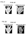
- the individual is authenticated by comparing the patterns of veins in the registered vein image retrieved using the user's ID and in the vein verification image read by the image capture device 100. For example, on comparing the vein patterns in the registered image and a verification image as in Fig. 21, the individual is authenticated as the individual in question. On the other hand, upon comparison of the vein patterns in a registered image and in a verification image as in Fig. 22, the individual is not authenticated (see for example Japanese Patent Laid-open No. 2004-062826).
- the IC card stores comparatively low-level characteristic data A (which may be leaked to outside parties), and comparatively high-level characteristic data B which should be kept confidential, taking into consideration the processing capacity of the IC card.
- Characteristic data A is transmitted from the IC card to an external device including a fingerprint sensor, and in the external device verification with the characteristic data A (called “primary verification") is performed.
- the verification result and characteristic data B' extracted from an image from the fingerprint sensor are transmitted to the IC card, and within the IC card verification with the characteristic data B (called “secondary verification”) is performed.
- One aspect of the invention provides a biometrics authentication device for detecting and registering biometrics characteristic data from a body part, capturing an image of the above body part, detecting biometrics characteristic data from the captured image, and verifying the characteristic data against the said registered characteristic data, to thus perform individual authentication.
- the device has an image capture device, for capturing images of the body part, scrambling and transmitting the images; an IC card reader/writer, for reading ard writing IC cards storing comparatively coarse first biometrics characteristic data and comparatively fine second characteristic data of a user; and a control unit for performing verification processing.
- the control unit can descramble the scrambled captured image, receive scrambled first characteristic data from the IC card, perform primary verification of the captured image and the first characteristic data, create final verification data, and scramble and transmit the final verification data to the IC card.
- the IC card can descramble the final verification data, and perform secondary verification with its stored second characteristic data.
- control unit aligns the (descrambled) captured image and the first characteristic data and create the above final verification data from the captured image.
- the control unit descrambles a scrambled captured image from the image capture device, creates the comparatively coarse first biometrics characteristic data and the comparatively fine second characteristic data for the user from the unscrambled captured image, scrambles and transmits to the IC card the first biometrics characteristic data, and transmits to the IC card the encrypted second characteristic data.
- the above IC card decrypts and stores the said encrypted second characteristic data.
- control unit scrambles the final verification data and transmits the data to the IC card reader/writer, and that at the IC card reader/writer the scrambled final verification data is encrypted and transmitted to the control unit.
- the image capture device is a unit able to capture images of blood vessels of the above user, that the first characteristic data be comparatively coarse (general, low definition characteristic data of the blood vessel images, and that the second characteristic data be comparatively fine (detailed) characteristic data of the blood vessel image.
- Another aspect of the invention provides an authentication method.
- biometrics authentication processing processing, biometrics characteristic data registration processing, biometrics characteristic data authentication processing, and other embodiments.
- Fig. 1 shows the configuration of a biometrics authentication system of an embodiment of the invention
- Fig. 2 shows the configuration of the business terminal device/bank window device of Fig. 1
- Fig. 3 is an external view of the palm image capture device of Fig. 1
- Fig. 2 shows the configuration of the business terminal device/bank window device of Fig. 1
- Fig. 3 is an external view of the palm image capture device of Fig. 1
- Fig. 4 shows the configuration of the image capture device of Fig. 3
- Fig. 5 is an external view of the automated transaction machine of Fig. 1
- Fig. 6 shows the configuration of the automated transaction machine of Fig. 5.
- Fig. 1 shows a palm vein pattern authentication system in a financial institution, as an example of a biometrics authentication system.
- a palm image capture device 1 explained in Fig. 3 and a branch office terminal (for example, a personal computer) 3 connected thereto are provided in an area 2 (e.g. window area) of the financial institution.
- a user requesting vein pattern authentication places his hand over the palm image capture device (hereafter called the "image capture device") 1.
- the image capture device 1 reads the palm image, and blood vessel extraction processing in the terminal 3 is used to extract the vein pattern, and this pattern is registered as vein data in the terminal device 3.
- This vein data is stored in a storage area 4a of a database server 4 connected to the terminal device 3 and in an individual card (for example, an IC card) 5 held by the user.
- the server 4 is connected to a bank window terminal device 8 of a bank window area 7 of the financial institution, and the bank window terminal device 8 is connected to an image capture device 1.
- the user inserts an IC card 5 into an IC card reader(explained in Fig. 2),and places his hand over the image capture device 1 provided in the bank window area 7.
- the image capture device 1 reads the palm image, and blood vessel image extraction processing by the window terminal device 8 extracts the vein pattern. Verification processing by the window terminal device 8 verifies (compares) this vein pattern, as vein data, against the vein data registered in the IC card 5 to authenticate the individual.
- the server 4 can be connected to an ATM (automated cash insertion/dispensing machine) 6 of the financial institution, and the transactions through vein authentication may be performed at the ATM 6.
- ATM automated cash insertion/dispensing machine
- the ATM 6 extracts the vein pattern (blood vessel image), verifies this, as vein data, against the vein data registered in the IC card 5 held by the user, and authenticates (determines the identify of) the individual.
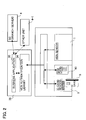
- Fig. 2 and Fig. 3 show the configurations of the service/window terminal devices 3, 8 of Fig. 1.
- an application 30 in the terminal devices 3 and 8 are mounted an application 30 and a vein authentication library (program) 34.
- a vein sensor (palm image capture device) 1 and IC card reader/writer 9 are connected to the terminal devices 3 and 8.
- the IC card reader/writer 9 reads and writes the IC chip and magnetic strip of the IC card 5 of a user.
- a security access module (SAM) is provided in the IC card reader/writer 9, and the module permits only authenticated access, to maintain the security of the IC card 5.
- the palm image capture device 1 of Fig. 1 and Fig. 2 has a sensor unit 18 mounted substantially in the center of a main unit 10.
- a front guide 14 is provided at a front portion (on the user side) of the sensor unit 18, and a rear guide 19 is provided at a rear portion.
- the front guide 14 is constructed of a sheet of transparent or substantially transparent synthetic resin.
- the front guide 14 serves the purposes of guiding the hand of the user in the front and of supporting the wrist. Hence above the sensor unit 18, the front guide 14 aids the user by guiding the wrist, and also supports the wrist. As a result, the attitude of the palm above the sensor unit 18, that is, the position, inclination, and size can be regulated above the sensor unit 18.
- the cross-sectional shape of the front guide 14 has a vertical body and, in the top portion, a horizontal portion 14-1 to support the wrist. A depression 14-2 is formed continuously in the center of the horizontal portion 14-1, to facilitate positioning of the wrist.
- the rear guide 19 serves to support the fingers.
- the sensor unit 18 is provided with an infrared sensor (CMOS sensor) and focusing lens 16, and with a distance sensor 15 in the center, and on the periphery thereof with a plurality of near-infrared light-emitting elements (LEDs) 12.
- CMOS sensor infrared sensor
- LEDs near-infrared light-emitting elements
- near-infrared LEDs are provided in eight places on the periphery, to emit near-infrared rays upwards.
- the readable region V of this sensor unit 18 is regulated by the relation between the sensor, focusing lens, and near-infrared light emission region. Hence the position and height of the front guide 14 are set such that the supported wrist is positioned in the readable region V.
- the palm When a hand 52 is extended with palm flat, the palm has maximum area, and moreover is flat, so that when the palm is subjected to image capture in the image capture region V of the sensor unit 18, an accurate vein pattern which can be used in registration and verification is obtained.
- the distance from the sensor unit 18 to the palm is within a prescribed range, a sharp, focused image is obtained by the sensor 16 of the sensor unit 18.
- the front guide 14 can guide and support the user's hand so that the position, inclination and height of the palm above the sensor unit 18 are made precise with respect to the image capture range of the sensor unit 18.
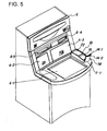
- the automated transaction machine (ATM) of Fig. 1 is explained.
- the ATM 6 has, on the front face thereof, a card insertion/ejection inlet 6-4; a bankbook insertion/ejection inlet 6-5; a paper currency insertion/dispensing inlet 6-3; a coin insertion/dispensing inlet 6-2; and a user operation panel 6-1 for operation and display.
- the image capture device 1-1 is provided on the side of the user operation panel 6-1.
- the sensor unit 18 explained in Fig. 4 is mounted on the forward side of the main unit 10 of the image capture device 1.
- On the forward portion (on the user side) of the sensor unit 18 is provided a front guide 14.
- the front guide 14 is constructed of a sheet of synthetic resin, transparent or substantially transparent.
- the cross-sectional shape of the front guide 14 has a vertical body and, in the top portion, a horizontal portion 14-1 to support the wrist.
- a depression 14-2 is formed continuously in the center of the horizontal portion 14-1, to facilitate positioning of the wrist.
- the sensor unit 18 of the main unit 10 faces rearward and is inclined upward, and a flat portion 22 is provided therebehind.
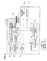
- the ATM 1 has a CIP (Card Reader Printer) unit 60 having a card insertion/ejection inlet 6-4; a bankbook (passbook) unit 64 having a bankbook insertion/ejection inlet 6-5; a paper currency/coin counting unit 66 having a paper currency insertion/dispensing inlet 6-3 and a coin insertion/dispensing inlet 6-2; an attendant operation portion 65; a control unit 67; a user operation panel 6-1 (UOP) for operation and display; and an image capture device (vein sensor) 1-1.
- CIP Card Reader Printer
- the CIP unit 60 has an IC card reader/writer 61 which reads and writes the magnetic stripe and IC chip of an IC card 5; a receipt printer 63 which records transactions on a receipt; a journal printer 62 which prints the history of transactionson journal forms; and a security access module (SAM) 70.
- SAM security access module
- the bankbook unit 64 prints transactions on pages of a bankbook, and when necessary turns the pages.
- the attendant operation portion 65 is for operations by an attendant, who can perform operations upon occurrence of a fault or during inspections according to status display.
- the paper currency/coin counting unit 66 differentiates, counts, and stores inserted paper currency and coins, and counts and dispenses paper currency and coins in the required quantities.
- the control unit 67 communicates with the server 4, and has an ATM application 68 which controls ATM operation and an authentication library (program) 69 for authentication processing.
- a portion of this ATM application 68 controls biometric authentication guidance screens of the UOP (user operation panel) 6-1 in connection with the authentication library 69.
- Fig. 7 is a block diagram of BIOMETRICS authentication processing in an embodiment of the invention
- Fig. 8 explains the detected blood vessel image in Fig. 7
- Fig. 9 explains verification processing in Fig. 7.
- the authentication library 34 of the service/window terminal devices 3, 8 connected to the image capture device 1 execute a series of registration and verification processes 34-1 to 34-5.
- the authentication library 69 of the control portion 67 in the ATM 6 executes similar processing.
- the service/window terminal devices 3, 8 and the control portion 67 of the ATM 6 have, for example, a CPU and various types of memory, interface circuitry, and other circuits necessary for data processing.
- the CPU executes a series of registration and verification processes 34-1 to 34-5.
- the IC chip of an IC card 5 also executes verification process 34-3.
- the CPU receives the distance measured by the distance sensor 15 from the image capture device 1-1 and judges whether the hand or other object is at a distance within a prescribed range from the sensor unit 18, and also detects the outline of the hand from the image captured by the sensor unit 18 and judges from the outline whether the image can be used in registration and verification processing. For example, the palm may not appear sufficiently in the image.
- Guidance message output processing 34-5 is used to output to the display of the service/window terminal devices 3, 8 a message guiding the palm of the hand leftward, rightward, forward, backward, upward or downward when the distance detected by the distance sensor 15 and the position of the hand according to outline extraction indicates that the hand or similar is outside the image capture range, and when the image captured cannot be used in registration and verification processing. By this means, the palm of the user is guided over the image capture device 1.
- Blood vessel image extraction processing 34-2 is used to extract a vein image from the image of the hand when hand outline detection processing 34-1 judges that an image has been captured with the hand held correctly. That is, as explained using Fig. 19 and Fig. 20, grayscale data of the image of the palm such as that of Fig. 9 is obtained through differences in reflectivity.
- the vein pattern image is an image like that shown in Fig. 8; the data is grayscale data such as that in Fig. 9.
- Registered blood vessel image retrieval processing 34-4 retrieves registered blood vessel image data A, B corresponding to the individual ID (account number) from the storage portion of the IC chip in the IC card 5 shown in Fig. 1, Fig. 2 and Fig. 6.
- Verification processing 34-3 compares the blood vessel image data N1 detected in the blood vessel image detection processing 34-2 with the registered blood vessel image data N2 as shown in Fig. 9, performs verification processing, and outputs the verification result.
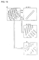
- Registration processing 34-5 divides the detected blood vessel image data into comparatively coarse-level (low detail) blood vessel image data A and comparatively fine-level (high detail) blood vessel image data B, as shown in Fig. 13, and stores the results in the IC chip 50 of the IC card 5, via the IC card reader/writer 9.
- Fig. 10 shows the flow of biometrics characteristic data registration processing in the IC card 5; Fig. 11 and Fig. 12 explain vein data registration in Fig. 10; and Fig. 13 explains the registration data A, B.
- the registered blood vessel image data A, B is created from the captured image and is registered in the IC card 5. Registration processing is explained using Fig. 11 to Fig. 13. As shown in Fig. 11 and Fig. 12, image data (plain data) R captured by the image capture device 1 is scrambled using a prescribed algorithm, and is transmitted to the authentication libraries 34 of the service/window terminal devices 3 and 8. In the authentication libraries 34, the transmitted image data is descrambled and returned to plain data. The authentication library 34 creates the registration data A, B from the plain data R. As shown in Fig. 13, the plain data (blood vessel image data) R can be classified into trunk Aa, thick branch Ab, and fine branch Ac leading to thick branch Ab, as is seen in Fig. 8.
- the trunk A1 and thick branches A2 are divided into the comparatively coarse characteristic data A, and the thinbranches Ac are classified as the comparatively finer characteristic data B, to create the registration data A, B.
- the registration data A is comparatively coarse, and so does not include finer details as characteristics, but indicates only rougher characteristics.
- the registration data B is comparatively finer, and so indicates finer(more detailed, precise) characteristics.
- the registration data A is scrambled in the authentication library 34, and the scrambled registration data A is stored in the IC chip 50 of the IC card 5.
- the registration data B requires greater security. Therefore the data B is scrambled by the authentication library 34, and the scrambled registration data B is sent to the security access module 90 of the IC card reader/writer 9.
- the security access module 90 descrambles and encrypts the scrambledregistration data B by using a secret key.
- the result is sent to the authentication library 34, and from the authentication library 34, the encrypted registration data B is sent to the IC chip 50 of the IC card 5.
- the CPU of the IC chip 50 decrypts the data B by using the secret key, and stores the registration data B in the memory of the IC chip 50.
- the validity of the registration data A and B can be confirmed.
- the plain data is automatically erased by the authentication library 34, so that confidentiality is further improved.
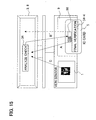
- Fig. 14 shows the flow of transaction processing, including biometrics characteristic data verification processing using an IC card 5; Fig. 15 and Fig. 16 explain the vein data verification of Fig. 14.
- the plain data and registration data A are aligned, e.g. mapped onto one another, and final verification data B' is created if alignment is successful.
- the fine branches Ac of the plain (image) data create the final verification data B' as the comparatively fine characteristic data.
- the authentication library 34 scrambles this final verification data B' and transmits it to the IC chip 50 of the IC card 5.
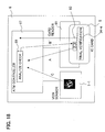
- Fig. 17 and Fig. 18 explain transaction processing, including biometrics authentication processing, in an automated transaction machine.
- step S56 the registration data A of the IC card 5 is used to perform primary verification (analysis verification) in the authentication library 69 of the control portion 67 in the ATM 6.
- step S58 Next, similarly to step S38, final verification is performed within the IC card 5.
- the password number is input using the UOP 6-1, and this is compared with the registered password number corresponding to the account number read from the magnetic stripe of the IC card 5. If the password verification result is satisfactory, the user inputs an amount to the UOP 6-1. The user confirms the amount, and communication with the host takes place.
- 'IC card' used in the description is not to be construed as meaning solely a (e.g. 2-D) card, but rather includes any suitable medium incorporating an IC chip and which can be read by a reader device.
Abstract
Description
- This invention relates to a biometrics authentication method and biometrics authentication device to authenticate individuals using features of a portion of the human body, and in particular relates to a biometrics authentication method and biometrics authentication device suitable for verifying registered blood vessel image information for a body part against blood vessel information detected for a body part, in a contactless manner.
- In the human body there are numerous parts which can be used to differentiate individuals, such as fingerprints of hand and toe, the retinas of the eyes, facial features, and blood vessel patterns. Advances in biometrics technology in recent years have been accompanied by proposals of various devices which identify biometric characteristics of such regions of the human body to authenticate individuals.
- Of these, because blood vessels in the palms and fingers and palm prints provide a comparatively large quantity of individual characteristic data, they are suited to individual authentication where high reliability is required. In particular, the patterns of blood vessels (veins) remain unchanged from the fetus throughout life, and are thought to be completely unique, and so are suited to individual authentication. Fig. 19 to Fig. 22 explain conventional technology for authentication using the palm. As shown in Fig. 19, at the time of registration or authentication, the user brings the palm of a
hand 110 close to animage capture device 100. Theimage capture device 100 emits near-infrared rays, which are incident on the palm of thehand 110. Theimage capture device 100 receives the near-infrared rays reflected from the palm of thehand 110 using a sensor. - As shown in Fig. 20, hemoglobin (haemoglobin) within the red corpuscles flowing in the
veins 112 has lost oxygen. This hemoglobin (reduced hemoglobin) absorbs near-infrared rays at wavelengths near 760 nanometers. Consequently when near-infrared rays are made incident on the palm of a hand, reflection is reduced only in the areas in which there are veins, and the (reduction in) intensity of the reflected near-infrared rays can be used to identify the positions of veins. - As shown in Fig. 19, a user first registers in a server and ID card the vein image data for the palm of his own hand, using the
image capture device 100 of Fig. 19. Next, in order to perform individual authentication, the user uses theimage capture device 100 of Fig. 19 to cause the vein image data of his own palm to be read. - The individual is authenticated by comparing the patterns of veins in the registered vein image retrieved using the user's ID and in the vein verification image read by the
image capture device 100. For example, on comparing the vein patterns in the registered image and a verification image as in Fig. 21, the individual is authenticated as the individual in question. On the other hand, upon comparison of the vein patterns in a registered image and in a verification image as in Fig. 22, the individual is not authenticated (see for example Japanese Patent Laid-open No. 2004-062826). - In a biometrics authentication system, measures must be taken to ensure that biometric characteristic data is not leaked to outside parties. Hence in the field of fingerprint authentication, a method of individual authentication has been proposed in which fingerprint characteristic data for an individual is registered in an IC card, and fingerprint characteristic data read from a fingerprint sensor is verified against the data within the IC card (Japanese Patent Laid-open No. 2000-293643).
- Further, in the above proposal, the IC card stores comparatively low-level characteristic data A (which may be leaked to outside parties), and comparatively high-level characteristic data B which should be kept confidential, taking into consideration the processing capacity of the IC card. Characteristic data A is transmitted from the IC card to an external device including a fingerprint sensor, and in the external device verification with the characteristic data A (called "primary verification") is performed. The verification result and characteristic data B' extracted from an image from the fingerprint sensor are transmitted to the IC card, and within the IC card verification with the characteristic data B (called "secondary verification") is performed.
- In this method, two stage verification operations are performed, externally and in the IC card, so that high-speed authentication can be achieved while maintaining security of biometric characteristic data.
- However, in order to further prevent leakage of characteristic data, security measures should also be applied to communication between the sensor, external device, and the IC card. In the above-described technology of the prior art, at the time of registration of characteristic data A, B in the IC card from the external device, data is encrypted and transmitted, and is decrypted and stored in the IC card (Japanese Patent Laid-open No. 2000-293643, paragraph 0055). And to perform secondary verification, characteristic data B' is encrypted and transmitted from the external device to the IC card, and is decrypted and used in secondary verification in the IC card (Japanese Patent Laid-open No. 2000-293643, paragraphs 0061, 0062).
- However, in the technology of the prior art, no security measures are taken with respect to biometric information sent from the sensor to the external device at the times of registration and verification. Consequently there are respects in which protection of biometric information detected by the sensor is lacking. And because characteristic data A which may be released externally is also encrypted, the IC card has had to bear the substantial processing burden of decrypting the characteristic data A and B.
- It is therefore desirable to provide an authentication (validation) processing method for a biometrics authentication device and a biometrics authentication device which reduce the load on the IC card while further improving the security of biometric information.
- It is further desirable to provide an authentication processing method for a biometrics authentication device and a biometrics authentication device which effectively utilize the processing functions of an external device to reduce the load on the IC card while further improving the security of biometric information.
- It is still further desirable to provide an authentication processing method for a biometrics authentication device and a biometrics authentication device which reduce the load on the IC card while further improving the security of complex biometric information.
- One aspect of the invention provides a biometrics authentication device for detecting and registering biometrics characteristic data from a body part, capturing an image of the above body part, detecting biometrics characteristic data from the captured image, and verifying the characteristic data against the said registered characteristic data, to thus perform individual authentication. The device has an image capture device, for capturing images of the body part, scrambling and transmitting the images; an IC card reader/writer, for reading ard writing IC cards storing comparatively coarse first biometrics characteristic data and comparatively fine second characteristic data of a user; and a control unit for performing verification processing. The control unitcan descramble the scrambled captured image, receive scrambled first characteristic data from the IC card, perform primary verification of the captured image and the first characteristic data, create final verification data, and scramble and transmit the final verification data to the IC card. The IC card can descramble the final verification data, and perform secondary verification with its stored second characteristic data.
- In this aspect , it is preferable that the control unit aligns the (descrambled) captured image and the first characteristic data and create the above final verification data from the captured image.
- Furthermore, it is preferable that at the time of registration of the said' characteristic data, the control unit descrambles a scrambled captured image from the image capture device, creates the comparatively coarse first biometrics characteristic data and the comparatively fine second characteristic data for the user from the unscrambled captured image, scrambles and transmits to the IC card the first biometrics characteristic data, and transmits to the IC card the encrypted second characteristic data. And the above IC card decrypts and stores the said encrypted second characteristic data.
- Also , it is preferable that the control unit scrambles the final verification data and transmits the data to the IC card reader/writer, and that at the IC card reader/writer the scrambled final verification data is encrypted and transmitted to the control unit.
- In addition , it is preferable that the image capture device is a unit able to capture images of blood vessels of the above user, that the first characteristic data be comparatively coarse (general, low definition characteristic data of the blood vessel images, and that the second characteristic data be comparatively fine (detailed) characteristic data of the blood vessel image.
- In this aspect , even through primary and second verification are performed by different units, because data is scrambled and transmitted, and moreover fine registration data B of importance for authentication is stored within the IC card while coarse registration data A is registered in the IC card in a scrambled state, descrambling processing need not be performed by the IC card. As the only processing within the IC card is descrambling of final verification data and verification, security is further improved, while keeping the load on the CPU of the IC chip in the IC card low.
- Another aspect of the invention provides an authentication method.
- Reference is now made, by way of example, to the accompanying drawings, in which:
- Fig. 1 shows a configuration of a biometric(biometrics) authentication system of an embodiment of the invention;
- Fig. 2 shows the configuration of the bank window device of Fig. 1;
- Fig. 3 is an external view of the image capture device of Fig. 1;
- Fig. 4 shows the configuration of the image capture device of Fig. 3;
- Fig. 5 is an external view of the ATM of Fig. 1;
- Fig. 6 is a block diagram of the ATM of Fig. 5;
- Fig. 7 is a functional block diagram of biometric information registration/verification processing in an embodiment of the invention;
- Fig. 8 explains the blood vessel image of Fig. 7;
- Fig. 9 explains the blood vessel image data of Fig. 8;
- Fig. 10 is a diagram of the flow of biometrics characteristic data registration processing in an embodiment of the invention;
- Fig. 11 shows the flow of data in the registration processing of Fig. 10;
- Fig. 12 explains the registration processing of Fig. 10;
- Fig. 13 explains the characteristic data A and B of Fig. 10;
- Fig. 14 is a diagram of the flow of biometrics characteristic data verification processing in an embodiment of the invention;
- Fig. 15 shows the flow of data in the verification processing of Fig. 14;
- Fig. 16 explains the verification processing of Fig. 14;
- Fig. 17 is a diagram of the flow of biometrics characteristic data verification processing in another embodiment of the invention;
- Fig. 18 shows the flow of data in the verification processing of Fig. 17;
- Fig. 19 explains a conventional palm image capture device;
- Fig. 20 explains the principle of a conventional palm image capture device;
- Fig. 21 explains conventional palm authentication technology; and,
- Fig. 22 further explains conventional palm authentication technology.
- Below, embodiments of the invention are explained in the order of a biometrics authentication system, biometrics authentication processing, biometrics characteristic data registration processing, biometrics characteristic data authentication processing, and other embodiments.
- Fig. 1 shows the configuration of a biometrics authentication system of an embodiment of the invention, Fig. 2 shows the configuration of the business terminal device/bank window device of Fig. 1, Fig. 3 is an external view of the palm image capture device of Fig. 1 and Fig. 2, Fig. 4 shows the configuration of the image capture device of Fig. 3, Fig. 5 is an external view of the automated transaction machine of Fig. 1, and Fig. 6 shows the configuration of the automated transaction machine of Fig. 5.
- Fig. 1 shows a palm vein pattern authentication system in a financial institution, as an example of a biometrics authentication system. A palm
image capture device 1 explained in Fig. 3 and a branch office terminal (for example, a personal computer) 3 connected thereto are provided in an area 2 (e.g. window area) of the financial institution. A user requesting vein pattern authentication places his hand over the palm image capture device (hereafter called the "image capture device") 1. Theimage capture device 1 reads the palm image, and blood vessel extraction processing in theterminal 3 is used to extract the vein pattern, and this pattern is registered as vein data in theterminal device 3. - This vein data is stored in a storage area 4a of a
database server 4 connected to theterminal device 3 and in an individual card (for example, an IC card) 5 held by the user. Theserver 4 is connected to a bankwindow terminal device 8 of abank window area 7 of the financial institution, and the bankwindow terminal device 8 is connected to animage capture device 1. - In order to make a withdrawal or perform some other financial transaction at the
bank window area 7 of the financial institution, the user inserts anIC card 5 into an IC card reader(explained in Fig. 2),and places his hand over theimage capture device 1 provided in thebank window area 7. Theimage capture device 1 reads the palm image, and blood vessel image extraction processing by thewindow terminal device 8 extracts the vein pattern. Verification processing by thewindow terminal device 8 verifies (compares) this vein pattern, as vein data, against the vein data registered in theIC card 5 to authenticate the individual. - The
server 4 can be connected to an ATM (automated cash insertion/dispensing machine) 6 of the financial institution, and the transactions through vein authentication may be performed at theATM 6. When a user employs theATM 6 to make a withdrawal or perform some other financial transaction, the user places his hand over an image capture device 1-1 provided in theATM 6. The image capture device 1-1 reads the palm image. Similarly to thewindow terminal device 8, theATM 6 extracts the vein pattern (blood vessel image), verifies this, as vein data, against the vein data registered in theIC card 5 held by the user, and authenticates (determines the identify of) the individual. - Fig. 2 and Fig. 3 show the configurations of the service/
window terminal devices terminal devices application 30 and a vein authentication library (program) 34. A vein sensor (palm image capture device) 1 and IC card reader/writer 9 are connected to theterminal devices - The IC card reader/
writer 9 reads and writes the IC chip and magnetic strip of theIC card 5 of a user. A security access module (SAM) is provided in the IC card reader/writer 9, and the module permits only authenticated access, to maintain the security of theIC card 5. - As shown in Fig. 3, the palm
image capture device 1 of Fig. 1 and Fig. 2 has asensor unit 18 mounted substantially in the center of amain unit 10. Afront guide 14 is provided at a front portion (on the user side) of thesensor unit 18, and arear guide 19 is provided at a rear portion. Thefront guide 14 is constructed of a sheet of transparent or substantially transparent synthetic resin. - The
front guide 14 serves the purposes of guiding the hand of the user in the front and of supporting the wrist. Hence above thesensor unit 18, thefront guide 14 aids the user by guiding the wrist, and also supports the wrist. As a result, the attitude of the palm above thesensor unit 18, that is, the position, inclination, and size can be regulated above thesensor unit 18. The cross-sectional shape of thefront guide 14 has a vertical body and, in the top portion, a horizontal portion 14-1 to support the wrist. A depression 14-2 is formed continuously in the center of the horizontal portion 14-1, to facilitate positioning of the wrist. Therear guide 19 serves to support the fingers. - As shown in Fig. 4, the
sensor unit 18 is provided with an infrared sensor (CMOS sensor) and focusinglens 16, and with adistance sensor 15 in the center, and on the periphery thereof with a plurality of near-infrared light-emitting elements (LEDs) 12. For example, near-infrared LEDs are provided in eight places on the periphery, to emit near-infrared rays upwards. - The readable region V of this
sensor unit 18 is regulated by the relation between the sensor, focusing lens, and near-infrared light emission region. Hence the position and height of thefront guide 14 are set such that the supported wrist is positioned in the readable region V. - When a
hand 52 is extended with palm flat, the palm has maximum area, and moreover is flat, so that when the palm is subjected to image capture in the image capture region V of thesensor unit 18, an accurate vein pattern which can be used in registration and verification is obtained. When the distance from thesensor unit 18 to the palm is within a prescribed range, a sharp, focused image is obtained by thesensor 16 of thesensor unit 18. - Hence as shown in Fig. 4, by supporting the
wrist 52 with thefront guide 14 above thesensor unit 18, thefront guide 14 can guide and support the user's hand so that the position, inclination and height of the palm above thesensor unit 18 are made precise with respect to the image capture range of thesensor unit 18. - Next, the automated transaction machine (ATM) of Fig. 1 is explained. As shown in Fig. 5, the
ATM 6 has, on the front face thereof, a card insertion/ejection inlet 6-4; a bankbook insertion/ejection inlet 6-5; a paper currency insertion/dispensing inlet 6-3; a coin insertion/dispensing inlet 6-2; and a user operation panel 6-1 for operation and display. - In this example, the image capture device 1-1 is provided on the side of the user operation panel 6-1. The
sensor unit 18 explained in Fig. 4 is mounted on the forward side of themain unit 10 of theimage capture device 1. On the forward portion (on the user side) of thesensor unit 18 is provided afront guide 14. Thefront guide 14 is constructed of a sheet of synthetic resin, transparent or substantially transparent. In order to serve the purposes of guiding the hand of the user in the front and of supporting the wrist, the cross-sectional shape of thefront guide 14 has a vertical body and, in the top portion, a horizontal portion 14-1 to support the wrist. A depression 14-2 is formed continuously in the center of the horizontal portion 14-1, to facilitate positioning of the wrist. - Further, the
sensor unit 18 of themain unit 10 faces rearward and is inclined upward, and aflat portion 22 is provided therebehind. - As shown in Fig. 6, the
ATM 1 has a CIP (Card Reader Printer)unit 60 having a card insertion/ejection inlet 6-4; a bankbook (passbook)unit 64 having a bankbook insertion/ejection inlet 6-5; a paper currency/coin counting unit 66 having a paper currency insertion/dispensing inlet 6-3 and a coin insertion/dispensing inlet 6-2; anattendant operation portion 65; acontrol unit 67; a user operation panel 6-1 (UOP) for operation and display; and an image capture device (vein sensor) 1-1. - The
CIP unit 60 has an IC card reader/writer 61 which reads and writes the magnetic stripe and IC chip of anIC card 5; areceipt printer 63 which records transactions on a receipt; ajournal printer 62 which prints the history of transactionson journal forms; and a security access module (SAM) 70. - The
bankbook unit 64 prints transactions on pages of a bankbook, and when necessary turns the pages. Theattendant operation portion 65 is for operations by an attendant, who can perform operations upon occurrence of a fault or during inspections according to status display. The paper currency/coin counting unit 66 differentiates, counts, and stores inserted paper currency and coins, and counts and dispenses paper currency and coins in the required quantities. - The
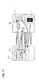
control unit 67 communicates with theserver 4, and has anATM application 68 which controls ATM operation and an authentication library (program) 69 for authentication processing. A portion of thisATM application 68 controls biometric authentication guidance screens of the UOP (user operation panel) 6-1 in connection with theauthentication library 69. - Fig. 7 is a block diagram of BIOMETRICS authentication processing in an embodiment of the invention, Fig. 8 explains the detected blood vessel image in Fig. 7, and Fig. 9 explains verification processing in Fig. 7.
- As shown in Fig. 7, the
authentication library 34 of the service/window terminal devices image capture device 1 execute a series of registration and verification processes 34-1 to 34-5. Theauthentication library 69 of thecontrol portion 67 in theATM 6 executes similar processing. The service/window terminal devices control portion 67 of theATM 6 have, for example, a CPU and various types of memory, interface circuitry, and other circuits necessary for data processing. The CPU executes a series of registration and verification processes 34-1 to 34-5. As explained below, the IC chip of anIC card 5 also executes verification process 34-3. - In distance/hand outline detection processing 34-1, the CPU receives the distance measured by the
distance sensor 15 from the image capture device 1-1 and judges whether the hand or other object is at a distance within a prescribed range from thesensor unit 18, and also detects the outline of the hand from the image captured by thesensor unit 18 and judges from the outline whether the image can be used in registration and verification processing. For example, the palm may not appear sufficiently in the image. - Guidance message output processing 34-5 is used to output to the display of the service/
window terminal devices 3, 8 a message guiding the palm of the hand leftward, rightward, forward, backward, upward or downward when the distance detected by thedistance sensor 15 and the position of the hand according to outline extraction indicates that the hand or similar is outside the image capture range, and when the image captured cannot be used in registration and verification processing. By this means, the palm of the user is guided over theimage capture device 1. - Blood vessel image extraction processing 34-2 is used to extract a vein image from the image of the hand when hand outline detection processing 34-1 judges that an image has been captured with the hand held correctly. That is, as explained using Fig. 19 and Fig. 20, grayscale data of the image of the palm such as that of Fig. 9 is obtained through differences in reflectivity. The vein pattern image is an image like that shown in Fig. 8; the data is grayscale data such as that in Fig. 9.
- Registered blood vessel image retrieval processing 34-4 retrieves registered blood vessel image data A, B corresponding to the individual ID (account number) from the storage portion of the IC chip in the
IC card 5 shown in Fig. 1, Fig. 2 and Fig. 6. Verification processing 34-3 compares the blood vessel image data N1 detected in the blood vessel image detection processing 34-2 with the registered blood vessel image data N2 as shown in Fig. 9, performs verification processing, and outputs the verification result. - Registration processing 34-5 divides the detected blood vessel image data into comparatively coarse-level (low detail) blood vessel image data A and comparatively fine-level (high detail) blood vessel image data B, as shown in Fig. 13, and stores the results in the
IC chip 50 of theIC card 5, via the IC card reader/writer 9. - In such a blood vessel image authentication system, the simultaneous achievement of confidentiality of blood vessel image data and faster authentication processing is advantageous for rapid biometric authentication.
- Next, the biometrics characteristic data registration processing outlined in Fig. 7 is explained in Fig. 10 to Fig. 13. Fig. 10 shows the flow of biometrics characteristic data registration processing in the
IC card 5; Fig. 11 and Fig. 12 explain vein data registration in Fig. 10; and Fig. 13 explains the registration data A, B. - (S10) First, a user who has applied for IC card biometric authentication presents his IC card and driver's licence or other personal identification at the bank window area, and is authenticated by the issuing source of the IC card.
- (S12) Upon being confirmed to be the individual in question, the user places his hand over the
image capture device 1 so that an image of his palm can be captured. - (S14) As explained above, the registered blood vessel image data A, B is created from the captured image and is registered in the
IC card 5. Registration processing is explained using Fig. 11 to Fig. 13. As shown in Fig. 11 and Fig. 12, image data (plain data) R captured by theimage capture device 1 is scrambled using a prescribed algorithm, and is transmitted to theauthentication libraries 34 of the service/window terminal devices authentication libraries 34, the transmitted image data is descrambled and returned to plain data. Theauthentication library 34 creates the registration data A, B from the plain data R. As shown in Fig. 13, the plain data (blood vessel image data) R can be classified into trunk Aa, thick branch Ab, and fine branch Ac leading to thick branch Ab, as is seen in Fig. 8. The trunk A1 and thick branches A2 are divided into the comparatively coarse characteristic data A, and the thinbranches Ac are classified as the comparatively finer characteristic data B, to create the registration data A, B. The registration data A is comparatively coarse, and so does not include finer details as characteristics, but indicates only rougher characteristics. The registration data B is comparatively finer, and so indicates finer(more detailed, precise) characteristics. - Hence the registration data A is scrambled in the
authentication library 34, and the scrambled registration data A is stored in theIC chip 50 of theIC card 5. On the other hand, the registration data B requires greater security. Therefore the data B is scrambled by theauthentication library 34, and the scrambled registration data B is sent to thesecurity access module 90 of the IC card reader/writer 9. Thesecurity access module 90 descrambles and encrypts the scrambledregistration data B by using a secret key. The result is sent to theauthentication library 34, and from theauthentication library 34, the encrypted registration data B is sent to theIC chip 50 of theIC card 5. The CPU of theIC chip 50 decrypts the data B by using the secret key, and stores the registration data B in the memory of theIC chip 50. - (S16) Next, execution proceeds to registration confirmation processing. That is, trial authentication is performed. For this purpose, the user again places his hand over the
image capture device 1, to capture an image of his palm. - (S18) A series of verification (analysis and comparison) operations are performed using the authentication processing of Fig. 14 and later.
- (S20) Similarly, secondary verification (final verification) is performed using the authentication processing of Fig. 14 and later. As a result, the validity of registration data A and B for authentication is confirmed.
- In this way data is scrambled, transmitted, and the registration data B which is more important (reliable, secure) for authentication is also encrypted. The encryption and decryption are performed not at the service/
window terminals writer 9, so that it is difficult for the encryption key and encryption algorithm to be identified on the side of the service/window terminal devices, and security is enhanced. At the time of registration, the CPU of theIC chip 50 in theIC card 5 performs only decryption processing of registration data B, and so the load imposed is small. - Further, because trial authentication is performed, the validity of the registration data A and B can be confirmed. Upon the end of registration, the plain data is automatically erased by the
authentication library 34, so that confidentiality is further improved. - Next, the biometrics characteristic data verification processing outlined in Fig. 7 is further explained in Fig. 14 to Fig. 18. Fig. 14 shows the flow of transaction processing, including biometrics characteristic data verification processing using an
IC card 5; Fig. 15 and Fig. 16 explain the vein data verification of Fig. 14. - (S30) First, a transaction is selected. At the window area, a user fills in a slip, and a teller performs input.
- (S32) The user inserts the
IC card 5 of the user into the IC card reader/writer 9, and the reader/writer 9 reads the magnetic stripe data (account number and similar) of theIC card 5. - (S34) Next, the user places his hand over the
image capture device 1, and an image of the palm is captured. - (S36) Using the registration data A of the
IC card 5, primary verification (analysis verification) is performed by theauthentication libraries 34 of service/window terminal devices image capture device 1 is scrambled using a prescribed algorithm, and is transmitted to theauthentication libraries 34 of the service/window terminal devices authentication library 34, the transmitted image data is descrambled to return it to plain data. Next, theauthentication library 34 reads scrambled registration data A from theIC card 5 and performs descrambling. In the example of Fig. 13, the registration data is returned to the comparatively coarse registration data A of trunks A1 and thick branches A2. - Next, the plain data and registration data A are aligned, e.g. mapped onto one another, and final verification data B' is created if alignment is successful. The fine branches Ac of the plain (image) data create the final verification data B' as the comparatively fine characteristic data. The
authentication library 34 scrambles this final verification data B' and transmits it to theIC chip 50 of theIC card 5. - (S38) Next, final verification is performed within the
IC card 5. That is, the CPU of theIC chip 50 in theIC card 5 descrambles the scrambled final verification data B', and performs verification (comparison) against the registration data B in memory. The verification result is presented to theauthentication library 34. - (S40) If the verification result is satisfactory, a password number is input, and this is compared with the registered password number corresponding to the account number read from the magnetic stripe of the
IC card 5. - (S42) If the result of password number comparison is satisfactory, the user inputs an amount.
- (S44) The user confirms the transaction.
- (S46) As a result, the service/
window terminal device - Thus data is scrambled and transmitted, and registration data B which is more important for authentication is stored within the
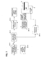
IC card 5. Because the registration data A is registered in theIC card 5 in scrambled form, when theIC card 5 pass the data A to theauthentication library 34, scrambling processing need not be performed within theIC card 5. Processing performed within theIC card 5 is descrambling and confirmation of the final verification data. Hence security is further improved, and the load on the CPU of theIC chip 50 in theIC card 5 is reduced. - Fig. 17 and Fig. 18 explain transaction processing, including biometrics authentication processing, in an automated transaction machine.
- (S50) First the transaction is selected. The transaction is selected on the UOP 6-1 of the
ATM 6. - (S52) The user inserts an
IC card 5 into the IC card reader/writer 9, which reads the magnetic stripe data (account number and similar). - (S54) Next, the user places his hand over the image capture device 1-1, and an image of the palm is captured.
- (S56) Similarly to step S36, the registration data A of the
IC card 5 is used to perform primary verification (analysis verification) in theauthentication library 69 of thecontrol portion 67 in theATM 6. - (S58) Next, similarly to step S38, final verification is performed within the
IC card 5. - (S60) If the verification result is satisfactory, the password number is input using the UOP 6-1, and this is compared with the registered password number corresponding to the account number read from the magnetic stripe of the
IC card 5. If the password verification result is satisfactory, the user inputs an amount to the UOP 6-1. The user confirms the amount, and communication with the host takes place. - (S62) Upon response from the host, the amount of cash is counted in the case of withdrawal, and a receipt is printed. The
IC card 5 and receipt are returned to the user, and cash is dispensed. - In the above-described embodiment, authentication using palm vein patterns was explained; but application to authentication using finger vein patterns, palm prints and other characteristics of the palm, as well as to fingerprints, facial features, and other biometrics authentication is also possible. Automated teller machines at financial institutions were explained, but application to automated ticket dispensing machines, automated vending machines, and automated equipment in other fields, as well as to computers, the opening and closing of doors requiring individual authentication, use in place of keys, and other tasks is also possible.
- In the above, embodiments of this invention have been explained; but various modifications can be made within the scope of the invention, and these modifications are not excluded from the scope of the invention.
- Even when primary and secondary verification are performed by different units, the data is scrambled and transmitted, and moreover registration data B which is more important to authentication is stored within the
IC card 5, and registration data A is registered in theIC card 5 in a scrambled state, so that scrambling processing need not be performed by the IC card. Because processing performed within the IC card is final verification data descrambling and verification, security can be further enhanced, and the load on the CPU of the IC chip in the IC card can be reduced. - The term 'IC card' used in the description is not to be construed as meaning solely a (e.g. 2-D) card, but rather includes any suitable medium incorporating an IC chip and which can be read by a reader device.
Claims (12)
- A biometric authentication device for verifying detected biometric characteristic data against registered biometric characteristic data, comprising:an image capture device for capturing an image of a living body part, scrambling and transmitting the image;an IC card reader/writer for reading from and writing to an IC card storing comparatively coarse first biometric characteristic data and comparatively fine second biometric characteristic data of a user; anda control unit for descrambling said scrambled captured image transmitted from the image capture device, receiving scrambled first biometric characteristic data from said IC card, performing primary verification of said captured image with said first biometric characteristic data, creating final verification data, and scrambling and transmitting to said IC card said final verification data,wherein said IC card is operable to descramble said scrambled final verification data, and to perform secondary verification with said stored second biometric characteristic data.
- The biometric authentication device according to Claim 1, wherein said control unit performs primary verification by aligning said captured image and said first biometric characteristic data and creates the final verification data from the captured image.
- The biometric authentication device according to Claim 1 or 2, wherein said control unit, at the time of registration of said biometric characteristic data, descrambles said scrambled captured image from the image capture device, creates the comparatively coarse first biometric characteristic data and the comparatively fine second biometric characteristic data for said user from said descrambled captured image, scrambles and transmits to said IC card said first biometric characteristic data, and transmits to said IC card said second biometric characteristic data as encrypted second biometric characteristic data,
and wherein said IC card stores said scrambled first biometric data, and decrypts and stores said encrypted second biometric characteristic data. - The biometric authentication device according to Claim 3, wherein said control unit scrambles said final verification data and transmits the scrambled final verification data to said IC card reader/writer,
and wherein said IC card reader/writer descrambles and encrypts said scrambled final verification data and transmits the encrypted final verification data to said control unit. - The biometric authentication device according to any preceding Claim, wherein said image capture device comprises a unit for capturing an image of blood vessels of a body part of said user,
and wherein said first biometric characteristic data is comparatively coarse characteristic data of said blood vessel image, and said second biometric characteristic data is comparatively fine characteristic data of said blood vessel image. - The biometric authentication device according to Claim 5, wherein said unit of said image capture device is operable to capture images of blood vessels of a palm of said user.
- A biometric authentication method for verifying detected biometric characteristic data from a living body against registered biometric characteristic data for individual authentication of a user, comprising the steps of:capturing an image of said living body, and scrambling and transmitting the captured image to a control unit;descrambling said transmitted scrambled capture image in said control unit;receiving comparatively coarse first biometric characteristic data of a user, in a scrambled state, from an IC card of the user;performing primary verification of said captured image with said first characteristic data, and creating final verification data in said control unit;scrambling and transmitting to said IC card said final verification data; anddescrambling said final verification data, and performing secondary verification with stored second characteristic data, in said IC card.
- The biometric authentication method according to Claim 7, wherein said primary verification and creation of final verification data comprises:a step of aligning said captured image and said first biometric characteristic data; anda step of creating said final verification data from said captured image.
- The biometric authentication method according to Claim 7 or 8, further comprising a registering step of registering said characteristic data,
wherein said registering step comprises the steps of:descrambling a scrambled captured image from the image capture device in said control unit;creating, from said descrambled captured image, comparatively coarse first biometric characteristic data and comparatively fine second biometric characteristic data of said user;scrambling said first biometric characteristic data, and transmitting the scrambled first biometric characteristic data to said IC card;transmitting encrypted second biometric characteristic data to said IC card;decrypting said encrypted second biometric characteristic data;and storing the scrambled first biometric characteristic data and the decrypted second biometric characteristic data, in said IC card. - The biometric authentication method according to any of Claims 7 to 9, further comprising the steps of:scrambling said final verification data and transmitting the scrambled final verification data to an IC card reader/writer;descrambling and encrypting said scrambled final verification data in said IC card reader/writer; andtransmitting said encrypted final verification data to said control unit from said IC card reader/writer.
- The biometric authentication method according to any of Claims 7 to 10, wherein said captured image comprises a blood vessel image of said living body,
and wherein said first biometric characteristic data is comparatively coarse characteristic data of said blood vessel image, and said second biometric characteristic data is comparatively fine characteristic data of said blood vessel image. - The biometric authentication method according to Claim 11, wherein said blood vessel image comprises blood vessels of a palm of said user.
Applications Claiming Priority (3)
| Application Number | Priority Date | Filing Date | Title |
|---|---|---|---|
| JP2004190438A JP4546169B2 (en) | 2004-06-28 | 2004-06-28 | An imaging device for palm authentication |
| JP2004224270A JP4515850B2 (en) | 2004-07-30 | 2004-07-30 | Biometric device guidance screen control method, biometric device and program thereof |
| JP2004296974A JP4657668B2 (en) | 2004-10-08 | 2004-10-08 | Biometric authentication method and biometric authentication device |
Publications (3)
| Publication Number | Publication Date |
|---|---|
| EP1612714A2 true EP1612714A2 (en) | 2006-01-04 |
| EP1612714A3 EP1612714A3 (en) | 2006-12-13 |
| EP1612714B1 EP1612714B1 (en) | 2009-06-24 |
Family
ID=35063373
Family Applications (1)
| Application Number | Title | Priority Date | Filing Date |
|---|---|---|---|
| EP05251674A Active EP1612714B1 (en) | 2004-06-28 | 2005-03-18 | Biometric authentication with transmission of scrambled data |
Country Status (4)
| Country | Link |
|---|---|
| EP (1) | EP1612714B1 (en) |
| AT (1) | ATE434800T1 (en) |
| DE (1) | DE602005015057D1 (en) |
| ES (1) | ES2327649T3 (en) |
Cited By (6)
| Publication number | Priority date | Publication date | Assignee | Title |
|---|---|---|---|---|
| EP1693774A3 (en) * | 2005-02-21 | 2006-09-06 | Hitachi-Omron Terminal Solutions, Corp. | Biometric authentication apparatus, terminal device and automatic transaction machine |
| WO2007096520A1 (en) * | 2006-02-24 | 2007-08-30 | Sagem Securite | Biodetector functioning without contact |
| WO2008074342A1 (en) * | 2006-12-19 | 2008-06-26 | Telecom Italia S.P.A. | Method and arrangement for secure user authentication based on a biometric data detection device |
| WO2009080089A1 (en) * | 2007-12-24 | 2009-07-02 | Telecom Italia S.P.A. | Biometrics based identification |
| CN101925914B (en) * | 2007-12-24 | 2016-12-14 | 意大利电信股份公司 | Mark based on bioassay |
| CN108027951A (en) * | 2015-09-03 | 2018-05-11 | 武礼伟仁株式会社 | A kind of multifunction card and card settlement terminal and card settling account system |
Citations (5)
| Publication number | Priority date | Publication date | Assignee | Title |
|---|---|---|---|---|
| US4993068A (en) * | 1989-11-27 | 1991-02-12 | Motorola, Inc. | Unforgeable personal identification system |
| EP0864996A2 (en) * | 1997-03-13 | 1998-09-16 | Hitachi, Ltd. | Portable electronic device and method for personal identification |
| EP1237091A1 (en) * | 1999-12-10 | 2002-09-04 | Fujitsu Limited | Personal authentication system and portable electronic device having personal authentication function using body information |
| DE10206843A1 (en) * | 2002-02-18 | 2003-09-04 | Orga Kartensysteme Gmbh | Data carrier such as chip-card, for biometric user-authentication has two different sets of biometric characteristics stored in carrier and associated with different stations |
| WO2004021884A1 (en) * | 2002-09-03 | 2004-03-18 | Fujitsu Limited | Individual identification device |
Family Cites Families (1)
| Publication number | Priority date | Publication date | Assignee | Title |
|---|---|---|---|---|
| US8190239B2 (en) * | 2002-09-03 | 2012-05-29 | Fujitsu Limited | Individual identification device |
-
2005
- 2005-03-18 AT AT05251674T patent/ATE434800T1/en not_active IP Right Cessation
- 2005-03-18 DE DE602005015057T patent/DE602005015057D1/en active Active
- 2005-03-18 EP EP05251674A patent/EP1612714B1/en active Active
- 2005-03-18 ES ES05251674T patent/ES2327649T3/en active Active
Patent Citations (5)
| Publication number | Priority date | Publication date | Assignee | Title |
|---|---|---|---|---|
| US4993068A (en) * | 1989-11-27 | 1991-02-12 | Motorola, Inc. | Unforgeable personal identification system |
| EP0864996A2 (en) * | 1997-03-13 | 1998-09-16 | Hitachi, Ltd. | Portable electronic device and method for personal identification |
| EP1237091A1 (en) * | 1999-12-10 | 2002-09-04 | Fujitsu Limited | Personal authentication system and portable electronic device having personal authentication function using body information |
| DE10206843A1 (en) * | 2002-02-18 | 2003-09-04 | Orga Kartensysteme Gmbh | Data carrier such as chip-card, for biometric user-authentication has two different sets of biometric characteristics stored in carrier and associated with different stations |
| WO2004021884A1 (en) * | 2002-09-03 | 2004-03-18 | Fujitsu Limited | Individual identification device |
Cited By (12)
| Publication number | Priority date | Publication date | Assignee | Title |
|---|---|---|---|---|
| EP1693774A3 (en) * | 2005-02-21 | 2006-09-06 | Hitachi-Omron Terminal Solutions, Corp. | Biometric authentication apparatus, terminal device and automatic transaction machine |
| KR100745625B1 (en) * | 2005-02-21 | 2007-08-03 | 히타치 오므론 터미널 솔루션즈 가부시키가이샤 | Biometric authentication apparatus, terminal device and automatic transaction machine |
| WO2007096520A1 (en) * | 2006-02-24 | 2007-08-30 | Sagem Securite | Biodetector functioning without contact |
| FR2897966A1 (en) * | 2006-02-24 | 2007-08-31 | Sagem Defense Securite | Biosensor for recognition and identification of user, has device forming and recording image when face of hand or finger is placed in plane portion, where portion is situated in placement volume of hand or finger deprived of contact surface |
| US20090046331A1 (en) * | 2006-02-24 | 2009-02-19 | Sagem Defense Securite | Contactless Biodetector |
| US8340371B2 (en) * | 2006-02-24 | 2012-12-25 | Morpho | Contactless biodetector |
| WO2008074342A1 (en) * | 2006-12-19 | 2008-06-26 | Telecom Italia S.P.A. | Method and arrangement for secure user authentication based on a biometric data detection device |
| US8955083B2 (en) | 2006-12-19 | 2015-02-10 | Telecom Italia S.P.A. | Method and arrangement for secure user authentication based on a biometric data detection device |
| WO2009080089A1 (en) * | 2007-12-24 | 2009-07-02 | Telecom Italia S.P.A. | Biometrics based identification |
| US8631243B2 (en) | 2007-12-24 | 2014-01-14 | Telecom Italia S.P.A. | Biometrics based identification |
| CN101925914B (en) * | 2007-12-24 | 2016-12-14 | 意大利电信股份公司 | Mark based on bioassay |
| CN108027951A (en) * | 2015-09-03 | 2018-05-11 | 武礼伟仁株式会社 | A kind of multifunction card and card settlement terminal and card settling account system |
Also Published As
| Publication number | Publication date |
|---|---|
| ES2327649T3 (en) | 2009-11-02 |
| EP1612714B1 (en) | 2009-06-24 |
| DE602005015057D1 (en) | 2009-08-06 |
| ATE434800T1 (en) | 2009-07-15 |
| EP1612714A3 (en) | 2006-12-13 |
Similar Documents
| Publication | Publication Date | Title |
|---|---|---|
| US7725733B2 (en) | Biometrics authentication method and biometrics authentication device | |
| EP1679666B1 (en) | Renewal method and renewal apparatus for a medium having biometric authentication functions | |
| US7742626B2 (en) | Biometrics system and biometrics method | |
| EP1739592B1 (en) | Biometric authentication and blood vessel image reading device | |
| US7508958B2 (en) | IC card access control method for biometrics authentication, biometrics authentication method, and biometrics authentication device | |
| US6871784B2 (en) | Security in mag-stripe card transactions | |
| US20060143117A1 (en) | Automated transaction control method, automated transaction device, and storage medium stored program for same | |
| US20070022303A1 (en) | Method of modification of authorization details for a biometrics authentication device, biometrics authentication method, and biometrics authentication device | |
| KR100788768B1 (en) | System for automatic teller machine and automatic cash transaction device | |
| KR100848926B1 (en) | Biometrics control method, a computer readable medium having stored thereon biometrics control program | |
| US20030046555A1 (en) | Identity verification using biometrics | |
| EP1612714B1 (en) | Biometric authentication with transmission of scrambled data | |
| US7508957B2 (en) | Method of registration of authorized agent information for a biometrics authentication device, authentication method for a biometrics authentication device, and biometrics authentication device | |
| Scheuermann et al. | Usability of biometrics in relation to electronic signatures | |
| JP4834785B2 (en) | Automatic cash deposit system and apparatus | |
| US20020122571A1 (en) | Identity verification using biometrics in analog format |
Legal Events
| Date | Code | Title | Description |
|---|---|---|---|
| PUAI | Public reference made under article 153(3) epc to a published international application that has entered the european phase |
Free format text: ORIGINAL CODE: 0009012 |
|
| AK | Designated contracting states |
Kind code of ref document: A2 Designated state(s): AT BE BG CH CY CZ DE DK EE ES FI FR GB GR HU IE IS IT LI LT LU MC NL PL PT RO SE SI SK TR |
|
| AX | Request for extension of the european patent |
Extension state: AL BA HR LV MK YU |
|
| PUAL | Search report despatched |
Free format text: ORIGINAL CODE: 0009013 |
|
| AK | Designated contracting states |
Kind code of ref document: A3 Designated state(s): AT BE BG CH CY CZ DE DK EE ES FI FR GB GR HU IE IS IT LI LT LU MC NL PL PT RO SE SI SK TR |
|
| AX | Request for extension of the european patent |
Extension state: AL BA HR LV MK YU |
|
| 17P | Request for examination filed |
Effective date: 20070606 |
|
| 17Q | First examination report despatched |
Effective date: 20070709 |
|
| AKX | Designation fees paid |
Designated state(s): AT BE BG CH CY CZ DE DK EE ES FI FR GB GR HU IE IS IT LI LT LU MC NL PL PT RO SE SI SK TR |
|
| GRAP | Despatch of communication of intention to grant a patent |
Free format text: ORIGINAL CODE: EPIDOSNIGR1 |
|
| GRAS | Grant fee paid |
Free format text: ORIGINAL CODE: EPIDOSNIGR3 |
|
| GRAA | (expected) grant |
Free format text: ORIGINAL CODE: 0009210 |
|
| RAP1 | Party data changed (applicant data changed or rights of an application transferred) |
Owner name: FUJITSU LIMITED Owner name: FUJITSU FRONTECH LIMITED |
|
| AK | Designated contracting states |
Kind code of ref document: B1 Designated state(s): AT BE BG CH CY CZ DE DK EE ES FI FR GB GR HU IE IS IT LI LT LU MC NL PL PT RO SE SI SK TR |
|
| REG | Reference to a national code |
Ref country code: GB Ref legal event code: FG4D |
|
| REG | Reference to a national code |
Ref country code: CH Ref legal event code: EP |
|
| REG | Reference to a national code |
Ref country code: IE Ref legal event code: FG4D |
|
| REF | Corresponds to: |
Ref document number: 602005015057 Country of ref document: DE Date of ref document: 20090806 Kind code of ref document: P |
|
| PG25 | Lapsed in a contracting state [announced via postgrant information from national office to epo] |
Ref country code: LT Free format text: LAPSE BECAUSE OF FAILURE TO SUBMIT A TRANSLATION OF THE DESCRIPTION OR TO PAY THE FEE WITHIN THE PRESCRIBED TIME-LIMIT Effective date: 20090624 Ref country code: AT Free format text: LAPSE BECAUSE OF FAILURE TO SUBMIT A TRANSLATION OF THE DESCRIPTION OR TO PAY THE FEE WITHIN THE PRESCRIBED TIME-LIMIT Effective date: 20090624 Ref country code: FI Free format text: LAPSE BECAUSE OF FAILURE TO SUBMIT A TRANSLATION OF THE DESCRIPTION OR TO PAY THE FEE WITHIN THE PRESCRIBED TIME-LIMIT Effective date: 20090624 |
|
| REG | Reference to a national code |
Ref country code: ES Ref legal event code: FG2A Ref document number: 2327649 Country of ref document: ES Kind code of ref document: T3 |
|
| PG25 | Lapsed in a contracting state [announced via postgrant information from national office to epo] |
Ref country code: SI Free format text: LAPSE BECAUSE OF FAILURE TO SUBMIT A TRANSLATION OF THE DESCRIPTION OR TO PAY THE FEE WITHIN THE PRESCRIBED TIME-LIMIT Effective date: 20090624 Ref country code: SE Free format text: LAPSE BECAUSE OF FAILURE TO SUBMIT A TRANSLATION OF THE DESCRIPTION OR TO PAY THE FEE WITHIN THE PRESCRIBED TIME-LIMIT Effective date: 20090924 Ref country code: PL Free format text: LAPSE BECAUSE OF FAILURE TO SUBMIT A TRANSLATION OF THE DESCRIPTION OR TO PAY THE FEE WITHIN THE PRESCRIBED TIME-LIMIT Effective date: 20090624 |
|
| NLV1 | Nl: lapsed or annulled due to failure to fulfill the requirements of art. 29p and 29m of the patents act | ||
| PG25 | Lapsed in a contracting state [announced via postgrant information from national office to epo] |
Ref country code: IS Free format text: LAPSE BECAUSE OF FAILURE TO SUBMIT A TRANSLATION OF THE DESCRIPTION OR TO PAY THE FEE WITHIN THE PRESCRIBED TIME-LIMIT Effective date: 20091024 Ref country code: EE Free format text: LAPSE BECAUSE OF FAILURE TO SUBMIT A TRANSLATION OF THE DESCRIPTION OR TO PAY THE FEE WITHIN THE PRESCRIBED TIME-LIMIT Effective date: 20090624 Ref country code: CZ Free format text: LAPSE BECAUSE OF FAILURE TO SUBMIT A TRANSLATION OF THE DESCRIPTION OR TO PAY THE FEE WITHIN THE PRESCRIBED TIME-LIMIT Effective date: 20090624 |
|
| PG25 | Lapsed in a contracting state [announced via postgrant information from national office to epo] |
Ref country code: SK Free format text: LAPSE BECAUSE OF FAILURE TO SUBMIT A TRANSLATION OF THE DESCRIPTION OR TO PAY THE FEE WITHIN THE PRESCRIBED TIME-LIMIT Effective date: 20090624 Ref country code: NL Free format text: LAPSE BECAUSE OF FAILURE TO SUBMIT A TRANSLATION OF THE DESCRIPTION OR TO PAY THE FEE WITHIN THE PRESCRIBED TIME-LIMIT Effective date: 20090624 Ref country code: BE Free format text: LAPSE BECAUSE OF FAILURE TO SUBMIT A TRANSLATION OF THE DESCRIPTION OR TO PAY THE FEE WITHIN THE PRESCRIBED TIME-LIMIT Effective date: 20090624 |
|
| PG25 | Lapsed in a contracting state [announced via postgrant information from national office to epo] |
Ref country code: BG Free format text: LAPSE BECAUSE OF FAILURE TO SUBMIT A TRANSLATION OF THE DESCRIPTION OR TO PAY THE FEE WITHIN THE PRESCRIBED TIME-LIMIT Effective date: 20090924 Ref country code: PT Free format text: LAPSE BECAUSE OF FAILURE TO SUBMIT A TRANSLATION OF THE DESCRIPTION OR TO PAY THE FEE WITHIN THE PRESCRIBED TIME-LIMIT Effective date: 20091024 |
|
| PG25 | Lapsed in a contracting state [announced via postgrant information from national office to epo] |
Ref country code: DK Free format text: LAPSE BECAUSE OF FAILURE TO SUBMIT A TRANSLATION OF THE DESCRIPTION OR TO PAY THE FEE WITHIN THE PRESCRIBED TIME-LIMIT Effective date: 20090624 |
|
| PLBE | No opposition filed within time limit |
Free format text: ORIGINAL CODE: 0009261 |
|
| STAA | Information on the status of an ep patent application or granted ep patent |
Free format text: STATUS: NO OPPOSITION FILED WITHIN TIME LIMIT |
|
| 26N | No opposition filed |
Effective date: 20100325 |
|
| PG25 | Lapsed in a contracting state [announced via postgrant information from national office to epo] |
Ref country code: MC Free format text: LAPSE BECAUSE OF NON-PAYMENT OF DUE FEES Effective date: 20100331 Ref country code: GR Free format text: LAPSE BECAUSE OF FAILURE TO SUBMIT A TRANSLATION OF THE DESCRIPTION OR TO PAY THE FEE WITHIN THE PRESCRIBED TIME-LIMIT Effective date: 20090925 |
|
| REG | Reference to a national code |
Ref country code: CH Ref legal event code: PL |
|
| PG25 | Lapsed in a contracting state [announced via postgrant information from national office to epo] |
Ref country code: IE Free format text: LAPSE BECAUSE OF NON-PAYMENT OF DUE FEES Effective date: 20100318 |
|
| PG25 | Lapsed in a contracting state [announced via postgrant information from national office to epo] |
Ref country code: LI Free format text: LAPSE BECAUSE OF NON-PAYMENT OF DUE FEES Effective date: 20100331 Ref country code: CH Free format text: LAPSE BECAUSE OF NON-PAYMENT OF DUE FEES Effective date: 20100331 |
|
| PG25 | Lapsed in a contracting state [announced via postgrant information from national office to epo] |
Ref country code: IT Free format text: LAPSE BECAUSE OF FAILURE TO SUBMIT A TRANSLATION OF THE DESCRIPTION OR TO PAY THE FEE WITHIN THE PRESCRIBED TIME-LIMIT Effective date: 20090624 |
|
| PG25 | Lapsed in a contracting state [announced via postgrant information from national office to epo] |
Ref country code: CY Free format text: LAPSE BECAUSE OF FAILURE TO SUBMIT A TRANSLATION OF THE DESCRIPTION OR TO PAY THE FEE WITHIN THE PRESCRIBED TIME-LIMIT Effective date: 20090624 |
|
| PG25 | Lapsed in a contracting state [announced via postgrant information from national office to epo] |
Ref country code: LU Free format text: LAPSE BECAUSE OF NON-PAYMENT OF DUE FEES Effective date: 20100318 Ref country code: HU Free format text: LAPSE BECAUSE OF FAILURE TO SUBMIT A TRANSLATION OF THE DESCRIPTION OR TO PAY THE FEE WITHIN THE PRESCRIBED TIME-LIMIT Effective date: 20091225 |
|
| PG25 | Lapsed in a contracting state [announced via postgrant information from national office to epo] |
Ref country code: TR Free format text: LAPSE BECAUSE OF FAILURE TO SUBMIT A TRANSLATION OF THE DESCRIPTION OR TO PAY THE FEE WITHIN THE PRESCRIBED TIME-LIMIT Effective date: 20090624 |
|
| PG25 | Lapsed in a contracting state [announced via postgrant information from national office to epo] |
Ref country code: RO Free format text: LAPSE BECAUSE OF FAILURE TO SUBMIT A TRANSLATION OF THE DESCRIPTION OR TO PAY THE FEE WITHIN THE PRESCRIBED TIME-LIMIT Effective date: 20090624 |
|
| REG | Reference to a national code |
Ref country code: FR Ref legal event code: PLFP Year of fee payment: 12 |
|
| REG | Reference to a national code |
Ref country code: FR Ref legal event code: PLFP Year of fee payment: 13 |
|
| REG | Reference to a national code |
Ref country code: FR Ref legal event code: PLFP Year of fee payment: 14 |
|
| REG | Reference to a national code |
Ref country code: DE Ref legal event code: R081 Ref document number: 602005015057 Country of ref document: DE Owner name: FUJITSU FRONTECH LTD., JP Free format text: FORMER OWNERS: FUJITSU LIMITED, KAWASAKI-SHI, KANAGAWA, JP; FUJITSU FRONTECH LTD., TOKIO/TOKYO, JP |
|
| REG | Reference to a national code |
Ref country code: ES Ref legal event code: PC2A Effective date: 20211011 |
|
| REG | Reference to a national code |
Ref country code: GB Ref legal event code: 732E Free format text: REGISTERED BETWEEN 20210923 AND 20210929 |
|
| REG | Reference to a national code |
Ref country code: DE Ref legal event code: R079 Ref document number: 602005015057 Country of ref document: DE Free format text: PREVIOUS MAIN CLASS: G06K0009000000 Ipc: G06V0010000000 |
|
| PGFP | Annual fee paid to national office [announced via postgrant information from national office to epo] |
Ref country code: FR Payment date: 20230208 Year of fee payment: 19 |
|
| PGFP | Annual fee paid to national office [announced via postgrant information from national office to epo] |
Ref country code: GB Payment date: 20230202 Year of fee payment: 19 Ref country code: DE Payment date: 20230131 Year of fee payment: 19 |
|
| PGFP | Annual fee paid to national office [announced via postgrant information from national office to epo] |
Ref country code: ES Payment date: 20230404 Year of fee payment: 19 |