EP1614521A1 - Tool insert for the gate of a hot runner nozzle for an injection moulding machine - Google Patents
Tool insert for the gate of a hot runner nozzle for an injection moulding machine Download PDFInfo
- Publication number
- EP1614521A1 EP1614521A1 EP05013232A EP05013232A EP1614521A1 EP 1614521 A1 EP1614521 A1 EP 1614521A1 EP 05013232 A EP05013232 A EP 05013232A EP 05013232 A EP05013232 A EP 05013232A EP 1614521 A1 EP1614521 A1 EP 1614521A1
- Authority
- EP
- European Patent Office
- Prior art keywords
- tool
- tool insert
- receiving
- head
- receiving head
- Prior art date
- Legal status (The legal status is an assumption and is not a legal conclusion. Google has not performed a legal analysis and makes no representation as to the accuracy of the status listed.)
- Granted
Links
- 238000001746 injection moulding Methods 0.000 title claims abstract description 8
- 239000002826 coolant Substances 0.000 claims abstract description 18
- 230000007704 transition Effects 0.000 claims description 5
- 230000001788 irregular Effects 0.000 claims description 3
- 238000003780 insertion Methods 0.000 claims 1
- 230000037431 insertion Effects 0.000 claims 1
- 238000001816 cooling Methods 0.000 description 5
- 238000002347 injection Methods 0.000 description 5
- 239000007924 injection Substances 0.000 description 5
- 238000000926 separation method Methods 0.000 description 4
- 230000008901 benefit Effects 0.000 description 3
- 239000000155 melt Substances 0.000 description 3
- 239000000463 material Substances 0.000 description 2
- 230000004323 axial length Effects 0.000 description 1
- 230000018109 developmental process Effects 0.000 description 1
- 230000000694 effects Effects 0.000 description 1
- 230000002349 favourable effect Effects 0.000 description 1
- 239000012943 hotmelt Substances 0.000 description 1
- 230000003993 interaction Effects 0.000 description 1
- 239000007788 liquid Substances 0.000 description 1
- 230000004048 modification Effects 0.000 description 1
- 238000012986 modification Methods 0.000 description 1
- 230000000717 retained effect Effects 0.000 description 1
- 239000007921 spray Substances 0.000 description 1
- 230000008646 thermal stress Effects 0.000 description 1
- XLYOFNOQVPJJNP-UHFFFAOYSA-N water Substances O XLYOFNOQVPJJNP-UHFFFAOYSA-N 0.000 description 1
Images


Classifications
-
- B—PERFORMING OPERATIONS; TRANSPORTING
- B29—WORKING OF PLASTICS; WORKING OF SUBSTANCES IN A PLASTIC STATE IN GENERAL
- B29C—SHAPING OR JOINING OF PLASTICS; SHAPING OF MATERIAL IN A PLASTIC STATE, NOT OTHERWISE PROVIDED FOR; AFTER-TREATMENT OF THE SHAPED PRODUCTS, e.g. REPAIRING
- B29C45/00—Injection moulding, i.e. forcing the required volume of moulding material through a nozzle into a closed mould; Apparatus therefor
- B29C45/17—Component parts, details or accessories; Auxiliary operations
- B29C45/26—Moulds
- B29C45/27—Sprue channels ; Runner channels or runner nozzles
- B29C45/2701—Details not specific to hot or cold runner channels
- B29C45/2708—Gates
- B29C45/2711—Gate inserts
-
- B—PERFORMING OPERATIONS; TRANSPORTING
- B29—WORKING OF PLASTICS; WORKING OF SUBSTANCES IN A PLASTIC STATE IN GENERAL
- B29C—SHAPING OR JOINING OF PLASTICS; SHAPING OF MATERIAL IN A PLASTIC STATE, NOT OTHERWISE PROVIDED FOR; AFTER-TREATMENT OF THE SHAPED PRODUCTS, e.g. REPAIRING
- B29C45/00—Injection moulding, i.e. forcing the required volume of moulding material through a nozzle into a closed mould; Apparatus therefor
- B29C45/17—Component parts, details or accessories; Auxiliary operations
- B29C45/26—Moulds
- B29C45/27—Sprue channels ; Runner channels or runner nozzles
- B29C45/2737—Heating or cooling means therefor
-
- B—PERFORMING OPERATIONS; TRANSPORTING
- B29—WORKING OF PLASTICS; WORKING OF SUBSTANCES IN A PLASTIC STATE IN GENERAL
- B29C—SHAPING OR JOINING OF PLASTICS; SHAPING OF MATERIAL IN A PLASTIC STATE, NOT OTHERWISE PROVIDED FOR; AFTER-TREATMENT OF THE SHAPED PRODUCTS, e.g. REPAIRING
- B29C45/00—Injection moulding, i.e. forcing the required volume of moulding material through a nozzle into a closed mould; Apparatus therefor
- B29C45/17—Component parts, details or accessories; Auxiliary operations
- B29C45/26—Moulds
- B29C45/27—Sprue channels ; Runner channels or runner nozzles
- B29C45/278—Nozzle tips
Definitions
- the present invention relates to a tool insert for the gate of a hot runner nozzle for an injection molding machine according to the preamble of claim 1.
- hot melt is injected from an injection molding machine either directly or via a hot runner manifold system by means of a hot runner nozzle in the mold (injection mold).
- the tool consists of a hot runner nozzle receiving the injection side, in which usually the outer shape (cavity) of the plastic part to be cast is located, and an ejector with the inner mold (core).
- the area in which the hot runner nozzle adjoins the tool and the plastic part is referred to as "gate”.
- the front, tool-side part of the hot runner nozzle with the gate area is in injection molding in a recess of the tool.
- the nozzle In the rear area, the nozzle is supported axially on the hot runner manifold block and is fixed with the front gate part by means of a precision seal in the tool. There, the nozzle is exposed to strong mechanical and thermal stresses.
- the gate area of the nozzle is subject to rapid wear, it is not formed as an integral part of the hot runner nozzle but as a replaceable tool bit.
- Important in injection molding is a thermal separation between nozzle and tool.
- the melt injected into the mold should solidify quickly, while the melt retained in the nozzle tip should remain liquid.
- It is therefore known to cool the tool insert by means of a coolant, for example water.
- a coolant for example water.
- the tool insert is provided on its outside in the amount of the two said channels with an annular groove, via which the coolant can flow from the feed channel to the discharge channel.
- the invention has for its object to further develop the known tool insert so that its cooling is significantly improved compared to the known cooling manner.
- the cavities can be obtained for example by flattening on the outer wall of the per se cylindrical receiving head of the tool insert.
- the flow connection between the adjacent cavities or chambers is preferably carried out in the greatest possible distance from the inflow and outflow channel for the coolant in the tool.
- edges of the cuttable projections can be easily defused by a slight flattening or rounding.
- 20 denotes a section of the tool (mold).
- 20a denotes the wall of the injection side of the tool and 20b the cavity.
- the tool insert 10 consists of a cylindrical fitting part 11 with flow channel 11a for the melt and a receiving head 12 for receiving a spray nozzle, not shown.
- the tool itself is a recess 21 which consists of a fitting bore 24 for receiving the fitting part 11 and a receiving bore 22 for receiving the receiving head 12 of the tool insert.
- the axial end position of the tool insert in the tool is determined by the interaction of a flange 18 on the tool facing away from the tool end of the tool and the depth of a corresponding sized, enlarged paragraph 28 at the entrance of the tool recess 21. Between the flange 18 and its support on the extended paragraph 28 is a seal, not shown.
- the axial end position of the tool insert is dimensioned so that when the flange 18 on the shoulder 28 a certain gap a ( Figures 2 and 6) between the truncated cone-shaped transition piece 19 of the tool insert and the bottom 29 of the receiving bore 22 is present.
- the normally circular cylindrical outer surface 12a of the receiving head 12 is formed over its entire length as a regular hexagonal body 17 with the exception of the flange 18 (see Figures 4, 5a and 5b).
- six cavities or chambers 23 are formed, which are separated from each other in the circumferential direction and substantially sealed against each other.
- the mutual separation of the chambers 23 can be achieved, for example, that the diameter of the hexagonal body, measured between two diametrically opposite edges, is selected to be greater than the diameter R of the receiving bore 22 (see Figure 5b). Subsequently, the hexagonal body can then be turned to the diameter R of the receiving bore, so that the wacky narrow extending in the longitudinal direction of the hexagonal cylinder surfaces 25 (see Figure 5c) adjacent chambers 23 separate from each other and also largely seal against each other.
- twisting off the edges 14 that can be seen in FIG. 5b can also be dispensed with in whole or in part. This is the case with the embodiment shown in FIGS. 1 to 5b.
- the diameter of the selected hexagonal body, measured between two diametrically opposite edges, is only slightly larger, for example 0.2 mm, than the diameter R of the receiving bore 22, so that on the outside of the receiving head projections 14 are formed, which in the inner wall of the Mounting hole 22 protrude. This has the consequence that when first inserting the tool insert 10 in the tool recess 21 extending in the longitudinal direction of the recording head 12 edges (projections) of the hexagonal body penetrate into the material of the tool injection side 20a and this guide grooves 15 in the wall of the receiving bore 22 cut or plane.
- the desired angular position of the tool insert is exactly predetermined by the already cut guide grooves 15.
- the defined angular position has the advantage that supply channel 31 and discharge channel 32 always assume the same favorable position relative to the respective adjacent chamber 23.
- a precisely defined rotational angle position is required when the transition between the fitting part 11 and the cavity 20b extends obliquely with respect to the longitudinal axis of the tool insert (not shown). In principle, sufficient to achieve these benefits already a single cut into the wall of the mounting hole projection on the recording head.
- connection between adjacent chambers instead of over the gap a also be created by the fact that at one or more suitable locations the edges of the hexagon over a certain axial length are taken back so far that a flow gap between adjacent chambers arises.
- the cooling is particularly intense when the feed channel 31 and the discharge channel 32 are as far above in the sense of Figure 2 and the connections between the chamber as far down as possible in the sense of Figure 2, ie in the region of the gap a lie.
- FIG. 5a shows the separation and sufficient take place in the upper part Seal between adjacent chamber substantially over along two lines of contact between the tool injection side and tool insert.
- Figure 6 shows a possible development of the embodiment shown in Figures 1 to 5b.
- the edges 14 of the hexagonal body are also removed at the lower end of the receiving head 12 in the sense of the drawing by a small distance c.
- This has the advantage that you get a good centering when inserting the tool insert 10 into the recess 21 in the tool in a simple manner.
- the cylindrical fitting part 11 has generally not yet reached the corresponding receiving bore 24, so that without the section c there is the danger of a non-concentric position of the receiving head 12 in the receiving bore 22.
- a groove 13 is provided in Figure 6 at the lower end of the cutting edge projection 14. On the one hand, it serves to obtain a sharp edge of the cutting edge and, on the other hand, to accommodate the chips that are produced when cutting the guide groove.
- the inventive idea is already realized by two somehow obtained cavities (chambers) between the wall of the receiving bore 22 and the receiving head 12 of the tool insert, one of which with the coolant supply channel 31 and the other with the coolant discharge channel 32 is in communication and wherein the two cavities are connected via a flow channel with each other, which is preferably offset in its altitude relative to the altitude of supply and discharge channel.
- the cavity can also be wholly or partly formed by removing material from the inner wall of the receiving bore 22 present in the tool.
Abstract
Description
Die vorliegende Erfindung bezieht sich auf einen Werkzeugeinsatz für den Anschnitt einer Heißkanaldüse für eine Spritzgießmaschine gemäß dem Oberbegriff des Anspruches 1.The present invention relates to a tool insert for the gate of a hot runner nozzle for an injection molding machine according to the preamble of claim 1.
Beim Spritzgießen wird heiße Schmelze von einer Spritzgießmaschine entweder direkt oder über ein Heißkanalverteilersystem mittels einer Heißkanaldüse in das Werkzeug (Spritzform) eingespritzt. Das Werkzeug besteht aus einer die Heißkanaldüse aufnehmenden Spritzseite, in welcher sich in der Regel die Außenform (Kavität) des zu gießenden Kunststoffteils befindet, und einer Auswerferseite mit der Innenform (Kern). Der Bereich, in welchem die Heißkanaldüse an das Werkzeug und an das Kunststoffteil anschließt, wird als "Anschnitt" bezeichnet. Der vordere, werkzeugseitige Teil der Heißkanaldüse mit dem Anschnittbereich steckt beim Spritzgießen in einer Ausnehmung des Werkzeugs. Im hinteren Bereich stützt sich die Düse axial am Heißkanalverteilerblock ab und ist mit dem vorderen Anschnittteil mittels Präzisionsdichtung im Werkzeug fixiert. Dort ist die Düse starken mechanischen und thermischen Beanspruchungen ausgesetzt.In injection molding hot melt is injected from an injection molding machine either directly or via a hot runner manifold system by means of a hot runner nozzle in the mold (injection mold). The tool consists of a hot runner nozzle receiving the injection side, in which usually the outer shape (cavity) of the plastic part to be cast is located, and an ejector with the inner mold (core). The area in which the hot runner nozzle adjoins the tool and the plastic part is referred to as "gate". The front, tool-side part of the hot runner nozzle with the gate area is in injection molding in a recess of the tool. In the rear area, the nozzle is supported axially on the hot runner manifold block and is fixed with the front gate part by means of a precision seal in the tool. There, the nozzle is exposed to strong mechanical and thermal stresses.
Da der Anschnittbereich der Düse folglich einem schnellen Verschleiß unterliegt, ist er nicht als integrales Teil der Heißkanaldüse ausgebildet, sondern als ein austauschbarer Werkzeugeinsatz. Wichtig ist beim Spritzgießen eine thermische Trennung zwischen Düse und Werkzeug. Die ins Werkzeug eingespritzte Schmelze soll schnell erstarren, während die in der Düsenspitze zurückgehaltene Schmelze flüssig bleiben soll. Es ist es daher bekannt, den Werkzeugeinsatz mittels eines Kühlmittels, zum Beispiel Wasser, zu kühlen. Zu diesem Zweck münden an der Wand der in der Regel zylindrischen Werkzeug-Ausnehmung im Werkzeug diametral gegenüberliegend ein Zuführ- und ein Abführkanal für ein dem Werkzeug zugeführtes Kühlmittel, und der Werkzeugeinsatz ist an seiner Außenseite in Höhe der beiden genannten Kanäle mit einer Ringnut versehen, über die das Kühlmittel vom Zuführkanal zum Abführkanal strömen kann.Consequently, since the gate area of the nozzle is subject to rapid wear, it is not formed as an integral part of the hot runner nozzle but as a replaceable tool bit. Important in injection molding is a thermal separation between nozzle and tool. The melt injected into the mold should solidify quickly, while the melt retained in the nozzle tip should remain liquid. It is therefore known to cool the tool insert by means of a coolant, for example water. For this purpose, on the wall of the generally cylindrical tool recess in the tool diametrically opposite a feed and a discharge channel for a tool supplied coolant, and the tool insert is provided on its outside in the amount of the two said channels with an annular groove, via which the coolant can flow from the feed channel to the discharge channel.
Der Erfindung liegt die Aufgabe zugrunde, den bekannten Werkzeugeinsatz derart weiter zu entwickeln, daß seine Kühlung im Vergleich zu der genannten bekannten Kühlungsweise wesentlich verbessert wird.The invention has for its object to further develop the known tool insert so that its cooling is significantly improved compared to the known cooling manner.
Zur Lösung dieser Aufgabe wird ein Werkzeugeinsatz gemäß dem Oberbegriff des Anspruches 1 vorgeschlagen, welcher erfindungsgemäß die im kennzeichnenden Teil des Anspruches 1 genannten Merkmale hat.To solve this problem, a tool insert according to the preamble of claim 1 is proposed, which according to the invention has the features mentioned in the characterizing part of claim 1.
Weitere Ausgestaltungen der Erfindung sind in den Unteransprüchen genannt.Further embodiments of the invention are mentioned in the subclaims.
Durch die Erfindung werden durch die geschaffenen Hohlräume oder Kammern zwischen dem Aufnahmekopf des Werkzeugeinsatzes und der Ausnehmung in dem Werkzeug Räume mit großen angrenzenden Flächen des Aufnahmekopfes geschaffen, an denen das Kühlmittel vorbeiströmt. Hierdurch wird eine intensivere Kühlung erreicht, als durch die oben genannte bekannte Ringnut am Aufnahmekopf, über die das Kühlmittel nur einen geringen Teil der Oberfläche des Aufnahmekopfes bestreicht.By the invention, spaces created by the created cavities or chambers between the receiving head of the tool insert and the recess in the tool with large adjacent surfaces of the receiving head, where the coolant flows past. This will be a more intense Cooling achieved, as by the above-mentioned known annular groove on the receiving head, over which the coolant sweeps only a small part of the surface of the recording head.
Die Hohlräume können beispielsweise durch Abflachungen an der Außenwand des an sich zylindrischen Aufnahmekopfes des Werkzeugeinsatzes gewonnen werden.The cavities can be obtained for example by flattening on the outer wall of the per se cylindrical receiving head of the tool insert.
Die Strömungsverbindung zwischen den benachbarten Hohlräumen oder Kammern erfolgt vorzugsweise in möglichst großer Entfernung von dem Zufluß- und Abflußkanal für das Kühlmittel im Werkzeug.The flow connection between the adjacent cavities or chambers is preferably carried out in the greatest possible distance from the inflow and outflow channel for the coolant in the tool.
Die Kanten der schneidfähigen Vorsprünge können durch eine leichte Abflachung oder Abrundung leicht entschärft werden.The edges of the cuttable projections can be easily defused by a slight flattening or rounding.
Anhand der in den Figuren gezeigten Ausführungsbeispiele soll die Erfindung näher erläutert werden. Es zeigen:
- Figur 1
- ein erstes Ausführungsbeispiel eines Werkzeugeinsatzes gemäß der Erfindung in Draufsicht, gesehen von der Seite des Werkzeugs,
- Figur 2
- den in ein Werkzeug eingesetzten Werkzeugeinsatz gemäß Figur 1 im Schitt längs der Linie A-A in Figur 1,
- Figur 3
- den in ein Werkzeug eingesetzten Werkzeugeinsatz gemäß Figur 1 im Schitt längs der Linie B-B in Figur 1,
- Figur 4
- den Werkzeugeinsatz gemäß den Figuren 1 bis 3 in perspektivischer Ansicht,
- Figur 5a
- im vergrößerten Maßstab ein Details im Schnitt längs der Linie C-C in Figur 2,
- Figur 5b
- im vergrößerten Maßstab ein Details im Schnitt längs der Linie D-D in Figur 2,
- Figur 5c
- eine zweite Ausführungsform der Erfindung, die eine Abwandlung der in den Figuren 1 bis 5b gezeigten Ausführungsform dargestellt,
Figur 6- eine dritte Ausführungsform der Erfindung, die sich lediglich im Bereich des Kreises A in Figur 2 vom der in den Figuren 1 bis 5b gezeigten Ausführungsform unterscheidet.
- FIG. 1
- a first embodiment of a tool insert according to the invention in plan view, seen from the side of the tool,
- FIG. 2
- the tool insert used in a tool according to FIG. 1 in the section along the line AA in FIG. 1,
- FIG. 3
- the tool insert used in a tool according to FIG. 1 in the section along the line BB in FIG. 1,
- FIG. 4
- the tool insert according to the figures 1 to 3 in a perspective view,
- FIG. 5a
- on an enlarged scale a detail in section along the line CC in Figure 2,
- FIG. 5b
- on an enlarged scale a detail in section along the line DD in Figure 2,
- FIG. 5c
- A second embodiment of the invention showing a modification of the embodiment shown in FIGS. 1 to 5b.
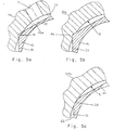
- FIG. 6
- A third embodiment of the invention, which differs only in the region of the circle A in Figure 2 from the embodiment shown in Figures 1 to 5b.
In Figur 2 ist mit 20 ein Ausschnitt aus dem Werkzeug (Form) bezeichnet. Dabei bezeichnet 20a die Wand der Spritzseite des Werkzeugs und 20b die Kavität. Der Werkzeugeinsatz 10 besteht aus einem zylindrischen Paßteil 11 mit Fließkanal 11a für die Schmelze und einem Aufnahmekopf 12 zur Aufnahme einer nicht dargestellten Spritzdüse. Im Werkzeug selbst befindet sich eine Ausnehmung 21, die aus einer Paßbohrung 24 zur Aufnahme des Paßteils 11 und eine Aufnahmebohrung 22 zur Aufnahme des Aufnahmekopfes 12 des Werkzeugeinsatzes besteht. Die Dichtung zwischen der nicht dargestellten Düse und Werkzeugeinsatz erfolgt über die in Figur 2 mit D bezeichneten Zylinderflächen von Werkzeugeinsatz 10 und Düse. Sowohl in der Werkzeug-Ausnehmung 21 als auch am Werkzeugeinsatz 10 erfolgt der Übergang von dem im Sinne der Figur 2 oberen zylindrischen Teil 22,12 zu dem unteren zylindrischen Teil 24,11 in der Regel über ein kegelstumpf-förmigesbergangsstück 19,29 (siehe auch Figur 6).In FIG. 2, 20 denotes a section of the tool (mold). Here, 20a denotes the wall of the injection side of the tool and 20b the cavity. The
Die achsiale Endlage des Werkzeugeinsatzes im Werkzeug wird bestimmt durch das Zusammenwirken eines Flansches 18 am vom Werkzeug abgewendeten Ende des Werkzeugeinsatzes und durch die Tiefe eines entsprechend bemessenen, erweiterten Absatzes 28 am Eingang der Werkzeug-Ausnehmung 21. Zwischen dem Flansch 18 und seiner Auflage auf dem erweiterten Absatz 28 befindet sich eine nicht dargestellte Dichtung. Die achsiale Endlage des Werkzeugeinsatzes ist so bemessen, daß bei Auflage des Flansches 18 auf dem Absatz 28 ein gewisser Spalt a (Figuren 2 und 6) zwischen dem kegelstumpf-förmigen Übergangsstück 19 des Werkzeugeinsatzes und dem Boden 29 der Aufnahmebohrung 22 vorhanden bleibt. Hierdurch wird neben der im folgenden beschriebenen Wirkung eine thermische Trennung und eine statisch bestimmte Anlage des Werkzeugeinsatzes in der Werkzeug-Ausnehmung 21 erreicht. Der soweit beschriebene Gegenstand gehört zum Stande der Technik.The axial end position of the tool insert in the tool is determined by the interaction of a
Bei dem in den Figuren 1 bis 5b gezeigten Ausführungsbeispiel der Erfindung ist mit Ausnahme des Flansches 18 die normalerweise kreiszylindrische äußeren Mantelfläche 12a des Aufnahmekopfes 12 über ihre gesamte Länge als ein regelmäßiger Sechskantkörper 17 ausgebildet (siehe Figuren 4, 5a und 5b). Dadurch bilden sich zwischen der kreiszylindrischen Innenwand der Aufnahmebohrung 22 und dem Sechskantkörper sechs Hohlräume oder Kammern 23, die in Umfangsrichtung voneinander getrennt und im wesentlichen gegeneinander abgedichtet sind. Von zwei diametral gegenüber liegenden Kammern 23 ist die eine, vorzugsweise mittig und oben, an den im Werkzeug vorgesehenen Zuführkanal 31 für das Kühlmittel angeschlossen und die andere an den Abführkanal 32 für das Kühlmittel.In the embodiment of the invention shown in Figures 1 to 5b, the normally circular cylindrical
Die gegenseitige Trennung der Kammern 23 kann beispielsweise dadurch erreicht werden, daß der Durchmesser des Sechskantkörpers, gemessen zwischen zwei diametral gegenüber liegenden Kanten, größer gewählt wird, als der Durchmesser R der Aufnahmebohrung 22 (siehe Figur 5b). Anschließend kann der Sechskantkörper dann auf das Durchmessermaß R der Aufnahmebohrung abgedreht werden, so daß die abgedrehten schmalen in Längsrichtung des Sechskants verlaufenden Zylinderflächen 25 (siehe Figur 5c) benachbarte Kammern 23 voneinander trennen und auch weitgehend gegeneinander abdichten.The mutual separation of the
Auf ein Abdrehen der in Figur 5b erkennbaren Kanten 14 kann jedoch auch ganz oder teilweise verzichtet werden. Dies ist der Fall bei dem in den Figuren 1 bis 5b gezeigten Ausführungsbeispiel. Der Durchmesser des dabei gewählten Sechskantkörpers, gemessen zwischen zwei diametral gegenüber liegenden Kanten, ist nur geringfügig größer, beispielsweise 0,2 mm, als der Durchmesser R der Aufnahmebohrung 22, so daß an der Außenseite des Aufnahmekopfes Vorsprünge 14 entstehen, die in die Innenwand der Aufnahmebohrung 22 hineinragen. Dies hat zur Folge, daß beim erstmaligen Einsetzen des Werkzeugeinsatzes 10 in die Werkzeug-Ausnehmung 21 die in Längsrichtung des Aufnahmekopfes 12 verlaufenden Kanten (Vorsprünge) des Sechskantkörpers in das Material der Werkzeugspritzseite 20a eindringen und hierbei Führungsnuten 15 in die Wand der Aufnahmebohrung 22 schneiden bzw. hobeln.However, twisting off the
Wird nach einer Demontage des Werkzeugeinsatzes dieser oder ein mit entsprechenden Vorsprüngen versehener neuer Werkzeugeinsatz in die Werkzeug-Ausnehmung 21 eingesetzt, so ist die gewünschte Drehwinkellage des Werkzeugeinsatzes durch die bereits eingeschnittenen Führungsnuten 15 exakt vorgegeben. Die definierte Drehwinkellage hat den Vorteil, daß Zuführkanal 31 und Abführkanal 32 stets dieselbe günstige Lage relativ zur jeweils angrenzenden Kammer 23 einnehmen. Ferner ist eine exakt definierte Drehwinkellage dann erforderlich, wenn der Übergang zwischen dem Paßteil 11 und der Kavität 20b schräg in Bezug auf die Längsachse des Werkzeugeinsatzes verläuft (nicht dargestellt). Im Prinzip genügt zur Erzielung dieser Vorteile bereits ein einziger in die Wand der Aufnahmebohrung einschneider Vorsprung am Aufnahmekopf.If, after disassembly of the tool insert, this or a new tool insert provided with corresponding projections is inserted into the
Bei dem gezeigten Ausführungsbeispiel besteht eine Verbindung zwischen den sechs Kammern 23 nur über den Spalt a zwischen dem kegelstumpf-förmigen Übergangsstück 19 und dem kegelstumpf-förmigen Boden des Aufnahmekopfes 12. Untersuchungen haben gezeigt, daß bei Zufuhr von Kühlmittel über den Zuführkanal 31 dieses in eine erste Kammer 23 einströmt, in dieser großflächig nach unten zum Spalt a strömt, dann in die beiden benachbarten Kammern praktisch bis zur oberen Begrenzung dieser Kammern einströmt und wieder zurückströmt, wie die durch die Pfeillinien b in Figur 4 angedeutet ist, und dann in diejenige Kammer einströmt, an die der Abführkanal 32 für das Kühlmittel angeschlossen ist. Auf diese Weise wird eine sehr effektive Kühlung des Werkzeugeinsatzes erzielt.In the embodiment shown, there is a connection between the six
Natürlich kann die Verbindung zwischen benachbarten Kammern statt über den Spalt a auch dadurch geschaffen werden, daß an einer oder mehreren geeigneten Stellen die Kanten des Sechskant über eine gewisse achsiale Länge soweit zurückgenommen werden, daß ein Durchflußspalt zwischen benachbarten Kammern entsteht. Die Kühlung ist jedoch besonders intensiv, wenn der Zuführkanal 31 und der Abführkanal 32 möglichst weit oben im Sinne der Figur 2 liegen und die Verbindungen zwischen den Kammer möglichst weit unten im Sinne der Figur 2, also im Bereich des Spaltes a, liegen.Of course, the connection between adjacent chambers instead of over the gap a also be created by the fact that at one or more suitable locations the edges of the hexagon over a certain axial length are taken back so far that a flow gap between adjacent chambers arises. However, the cooling is particularly intense when the
Um die für das erstmalige Eindrücken des Werkzeugeinsatz in das Werkzeug erforderliche Kraft klein zu halten, erstreckt sich bei dem gezeigten Ausführungsbeispiel der Figuren 1 bis 5b die nicht weggenommene Kante 14 nur über einen im Sinne der Figur 2 unteren Abschnitt 17a des Aufnahmekopfes 12. Die Figuren 5a und 5b zeigen den sich dabei ergebenden Aufbau im oberen beziehungsweise unteren Teil der Aufnahmebohrung 22 bei eingesetztem Werkzeugeinsatz. Wie Figur 5a zeigt, erfolgt dabei im oberen Teil die Trennung und ausreichende Dichtung zwischen benachbarten Kammer im wesentlichen über längs zweier Berührungslinien zwischen Werkzeugspritzseite und Werkzeugeinsatz.In order to keep the required for the first time impressions of the tool insert force in the tool small, extends in the illustrated embodiment of Figures 1 to 5b not taken away
Figur 6 zeigt eine mögliche Weiterbildung der in den Figuren 1 bis 5b gezeigten Ausführungsform. Hier sind die Kanten 14 des Sechskantkörpers auch an dem im Sinne der Zeichnung unteren Ende des Aufnahmekopfes 12 um eine kleine Strecke c weggenommen. Dies hat den Vorteil, daß man beim Einsetzen des Werkzeugeinsatzes 10 in die Ausnehmung 21 im Werkzeug auf einfache Weise eine gute Zentrierung erhält. Wenn die Schneidkante 14 ansetzt, hat das zylindrische Paßteil 11 nämlich in der Regel noch nicht die entsprechende Aufnahmebohrung 24 erreicht, so daß ohne den Abschnitt c die Gefahr einer nicht-konzentrischen Lage des Aufnahmekopfes 12 in der Aufnahmebohrung 22 besteht.Figure 6 shows a possible development of the embodiment shown in Figures 1 to 5b. Here, the
Außerdem ist in Figur 6 am unteren Ende des Schneidkantenvorsprungs 14 eine Rille 13 vorgesehen. Sie dient einerseits dazu, einen scharfen Schneidkantenanfang zu erhalten und zum anderen zur Aufnahme der beim Schneiden der Führungsnut anfallenden Späne.In addition, a
Die Erfindung ist nicht auf die gezeigten Ausführungsbeispiele beschränkt, sondern kann im Rahmen der Patentansprüche in vielfacher Weise variiert werden. So kann der in den Figuren gezeigte regelmäßigen Sechskantkörper 17 durch irgendeinen anderer regelmäßigen oder unregelmäßigen Mehrkantkörper ersetzt werden.The invention is not limited to the exemplary embodiments shown, but can be varied within the scope of the claims in many ways. Thus, the regular
Im Prinzip wird die erfinderische Idee bereits durch zwei irgendwie beschaffenen Hohlräume (Kammern) zwischen der Wand der Aufnahmebohrung 22 und dem Aufnahmekopf 12 des Werkzeugeinsatzes verwirklicht, von denen der eine mit dem Kühlmittel-Zuführkanal 31 und der andere mit dem Kühlmittel-Abführkanal 32 in Verbindung steht und wobei die beiden Hohlräume über einen Strömungskanal miteinander in Verbindung stehen, der vorzugsweise in seiner Höhenlage gegenüber der Höhenlage von Zuführ- und Abführkanal versetzt ist. Grundsätzlich kann der Hohlraum auch ganz oder teilweise durch Herausnahme von Material aus der Innenwand der im Werkzeug vorhandenen Aufnahmebohrung 22 gebildet werden.In principle, the inventive idea is already realized by two somehow obtained cavities (chambers) between the wall of the receiving bore 22 and the receiving
Claims (10)
Applications Claiming Priority (1)
| Application Number | Priority Date | Filing Date | Title |
|---|---|---|---|
| DE102004033469A DE102004033469B3 (en) | 2004-07-10 | 2004-07-10 | Tool insert for the cutting of a hot runner nozzle for an injection molding machine |
Publications (2)
| Publication Number | Publication Date |
|---|---|
| EP1614521A1 true EP1614521A1 (en) | 2006-01-11 |
| EP1614521B1 EP1614521B1 (en) | 2014-12-17 |
Family
ID=34980212
Family Applications (1)
| Application Number | Title | Priority Date | Filing Date |
|---|---|---|---|
| EP05013232.3A Active EP1614521B1 (en) | 2004-07-10 | 2005-06-18 | Tool insert for the gate of a hot runner nozzle for an injection moulding machine |
Country Status (3)
| Country | Link |
|---|---|
| US (1) | US7316560B2 (en) |
| EP (1) | EP1614521B1 (en) |
| DE (1) | DE102004033469B3 (en) |
Families Citing this family (4)
| Publication number | Priority date | Publication date | Assignee | Title |
|---|---|---|---|---|
| US7370417B2 (en) | 2005-12-09 | 2008-05-13 | Mold-Masters (2007) Limited | Method of installing a mold gate insert in an injection molding apparatus |
| DE202008006865U1 (en) | 2008-05-15 | 2008-07-24 | Stemke, Gudrun | Nozzle cooling for forming tools |
| DE102010000196A1 (en) | 2010-01-26 | 2011-07-28 | RPC Bramlage GmbH, 49393 | Plastic injection tool and method for plastic injection |
| CN109789618B (en) * | 2016-10-05 | 2021-11-30 | 赫斯基注塑系统有限公司 | Multi-material hot runner nozzle |
Citations (6)
| Publication number | Priority date | Publication date | Assignee | Title |
|---|---|---|---|---|
| US4266723A (en) * | 1979-11-02 | 1981-05-12 | Incoe Corporation | Nozzle for injection molding machines |
| JPS63120625A (en) * | 1986-11-08 | 1988-05-25 | Mitsubishi Metal Corp | Injection mold |
| JPH0524076A (en) * | 1991-07-24 | 1993-02-02 | Fuji Photo Film Co Ltd | Injection mold |
| JPH07290539A (en) * | 1994-04-26 | 1995-11-07 | Mitsubishi Materials Corp | Hot runner molds |
| JPH10286843A (en) * | 1997-04-11 | 1998-10-27 | Meiki Co Ltd | Stringing prevention structure for injection molding equipment |
| EP0933186A1 (en) * | 1998-02-02 | 1999-08-04 | Mold-Masters Limited | Injection molding cooled gate insert |
Family Cites Families (5)
| Publication number | Priority date | Publication date | Assignee | Title |
|---|---|---|---|---|
| US4622001A (en) * | 1985-03-12 | 1986-11-11 | Electra Form, Inc. | Cavity cooling system |
| DE3811112A1 (en) * | 1988-03-31 | 1989-10-12 | Fritz Mueller | INJECTION MOLDING PROCESS FOR PLASTICS AND INJECTION MOLD |
| US4950154A (en) * | 1989-07-03 | 1990-08-21 | Moberg Clifford A | Combination injection mold and sprue bushing |
| CA2037186C (en) * | 1991-02-27 | 2002-07-30 | Jobst Ulrich Gellert | Injection molding probe with a longitudinal thermocouple bore and off center heating element |
| US6394785B1 (en) * | 2000-11-20 | 2002-05-28 | Top Grade Molds Ltd. | Nozzle for injection mold |
-
2004
- 2004-07-10 DE DE102004033469A patent/DE102004033469B3/en active Active
-
2005
- 2005-06-18 EP EP05013232.3A patent/EP1614521B1/en active Active
- 2005-07-08 US US11/160,788 patent/US7316560B2/en active Active
Patent Citations (6)
| Publication number | Priority date | Publication date | Assignee | Title |
|---|---|---|---|---|
| US4266723A (en) * | 1979-11-02 | 1981-05-12 | Incoe Corporation | Nozzle for injection molding machines |
| JPS63120625A (en) * | 1986-11-08 | 1988-05-25 | Mitsubishi Metal Corp | Injection mold |
| JPH0524076A (en) * | 1991-07-24 | 1993-02-02 | Fuji Photo Film Co Ltd | Injection mold |
| JPH07290539A (en) * | 1994-04-26 | 1995-11-07 | Mitsubishi Materials Corp | Hot runner molds |
| JPH10286843A (en) * | 1997-04-11 | 1998-10-27 | Meiki Co Ltd | Stringing prevention structure for injection molding equipment |
| EP0933186A1 (en) * | 1998-02-02 | 1999-08-04 | Mold-Masters Limited | Injection molding cooled gate insert |
Non-Patent Citations (4)
| Title |
|---|
| PATENT ABSTRACTS OF JAPAN vol. 012, no. 364 (M - 747) 29 September 1988 (1988-09-29) * |
| PATENT ABSTRACTS OF JAPAN vol. 017, no. 300 (M - 1426) 8 June 1993 (1993-06-08) * |
| PATENT ABSTRACTS OF JAPAN vol. 1996, no. 03 29 March 1996 (1996-03-29) * |
| PATENT ABSTRACTS OF JAPAN vol. 1999, no. 01 29 January 1999 (1999-01-29) * |
Also Published As
| Publication number | Publication date |
|---|---|
| US20060024402A1 (en) | 2006-02-02 |
| US7316560B2 (en) | 2008-01-08 |
| DE102004033469B3 (en) | 2006-04-13 |
| EP1614521B1 (en) | 2014-12-17 |
Similar Documents
| Publication | Publication Date | Title |
|---|---|---|
| EP2032295B1 (en) | Junction between two components of a rotating tool system | |
| DE60209642T2 (en) | Trimmer head with fixed cutting line with automatic loading | |
| EP2406029B1 (en) | Cutting tool for a machine tool | |
| EP2676781B1 (en) | Method and device for producing a single-piece multi-component injection moulded brush | |
| DE10012810A1 (en) | Rolling body screw drive has at least one re-orientation element fastened to threaded nut encompassing threaded spindle by means of fixing pins extending parallel to spindle's longitudinal axis | |
| DE4125853A1 (en) | ELASTIC ADJUSTMENT SCREW | |
| DE102006004928A1 (en) | Improved neck back cooling | |
| EP1614521B1 (en) | Tool insert for the gate of a hot runner nozzle for an injection moulding machine | |
| EP0800907B1 (en) | Needle shut-off nozzle with injection mold and shut-off needle | |
| DE102005059130B4 (en) | Device for injection molding of molded parts | |
| DE19956214A1 (en) | Open injection nozzle | |
| DE4421566C1 (en) | Plastic piston mfr. | |
| DE10024625B4 (en) | Mold nest for plastics processing | |
| DE1550419B2 (en) | VALVE CAP AND PROCESS FOR ITS MANUFACTURING | |
| EP1911564B1 (en) | Injection nozzle for introducing a molten mass into a plastic injection moulding form | |
| EP1568463B1 (en) | Tool insert with the associated tool component for the gate of a hot runner nozzle for an injection moulding machine | |
| DE19713874B4 (en) | Device for introducing gas into a mold | |
| EP0992332A2 (en) | Hot channel closure | |
| AT396574B (en) | DEVICE FOR MAKING TWO OR MORE EXCLUSIONS AT PRESET DISTANCES IN A WALL | |
| DE102020112808A1 (en) | Cutting tool and method of making a cutting tool | |
| DE3729424C2 (en) | ||
| DE1937751A1 (en) | Plastic spool for high frequency solenoids | |
| DE202018006125U1 (en) | Tool for machining a workpiece | |
| DE19916249A1 (en) | Mold for use in a gas assisted injection molding system and adjustable overflow pin assembly for use therein | |
| DE3519592C2 (en) | Rotary impact drill bit |
Legal Events
| Date | Code | Title | Description |
|---|---|---|---|
| PUAI | Public reference made under article 153(3) epc to a published international application that has entered the european phase |
Free format text: ORIGINAL CODE: 0009012 |
|
| AK | Designated contracting states |
Kind code of ref document: A1 Designated state(s): AT BE BG CH CY CZ DE DK EE ES FI FR GB GR HU IE IS IT LI LT LU MC NL PL PT RO SE SI SK TR |
|
| AX | Request for extension of the european patent |
Extension state: AL BA HR LV MK YU |
|
| 17P | Request for examination filed |
Effective date: 20060224 |
|
| AKX | Designation fees paid |
Designated state(s): AT BE BG CH CY CZ DE DK EE ES FI FR GB GR HU IE IS IT LI LT LU MC NL PL PT RO SE SI SK TR |
|
| 17Q | First examination report despatched |
Effective date: 20070222 |
|
| GRAP | Despatch of communication of intention to grant a patent |
Free format text: ORIGINAL CODE: EPIDOSNIGR1 |
|
| INTG | Intention to grant announced |
Effective date: 20140303 |
|
| GRAP | Despatch of communication of intention to grant a patent |
Free format text: ORIGINAL CODE: EPIDOSNIGR1 |
|
| INTG | Intention to grant announced |
Effective date: 20140604 |
|
| GRAS | Grant fee paid |
Free format text: ORIGINAL CODE: EPIDOSNIGR3 |
|
| GRAP | Despatch of communication of intention to grant a patent |
Free format text: ORIGINAL CODE: EPIDOSNIGR1 |
|
| INTG | Intention to grant announced |
Effective date: 20140915 |
|
| GRAA | (expected) grant |
Free format text: ORIGINAL CODE: 0009210 |
|
| AK | Designated contracting states |
Kind code of ref document: B1 Designated state(s): AT BE BG CH CY CZ DE DK EE ES FI FR GB GR HU IE IS IT LI LT LU MC NL PL PT RO SE SI SK TR |
|
| REG | Reference to a national code |
Ref country code: GB Ref legal event code: FG4D Free format text: NOT ENGLISH |
|
| REG | Reference to a national code |
Ref country code: CH Ref legal event code: EP |
|
| REG | Reference to a national code |
Ref country code: IE Ref legal event code: FG4D Free format text: LANGUAGE OF EP DOCUMENT: GERMAN |
|
| REG | Reference to a national code |
Ref country code: AT Ref legal event code: REF Ref document number: 701550 Country of ref document: AT Kind code of ref document: T Effective date: 20150115 |
|
| REG | Reference to a national code |
Ref country code: DE Ref legal event code: R096 Ref document number: 502005014619 Country of ref document: DE Effective date: 20150129 |
|
| REG | Reference to a national code |
Ref country code: CH Ref legal event code: NV Representative=s name: PATENTANWAELTE SCHAAD, BALASS, MENZL AND PARTN, CH |
|
| PG25 | Lapsed in a contracting state [announced via postgrant information from national office to epo] |
Ref country code: FI Free format text: LAPSE BECAUSE OF FAILURE TO SUBMIT A TRANSLATION OF THE DESCRIPTION OR TO PAY THE FEE WITHIN THE PRESCRIBED TIME-LIMIT Effective date: 20141217 Ref country code: LT Free format text: LAPSE BECAUSE OF FAILURE TO SUBMIT A TRANSLATION OF THE DESCRIPTION OR TO PAY THE FEE WITHIN THE PRESCRIBED TIME-LIMIT Effective date: 20141217 |
|
| REG | Reference to a national code |
Ref country code: LT Ref legal event code: MG4D |
|
| PG25 | Lapsed in a contracting state [announced via postgrant information from national office to epo] |
Ref country code: GR Free format text: LAPSE BECAUSE OF FAILURE TO SUBMIT A TRANSLATION OF THE DESCRIPTION OR TO PAY THE FEE WITHIN THE PRESCRIBED TIME-LIMIT Effective date: 20150318 Ref country code: SE Free format text: LAPSE BECAUSE OF FAILURE TO SUBMIT A TRANSLATION OF THE DESCRIPTION OR TO PAY THE FEE WITHIN THE PRESCRIBED TIME-LIMIT Effective date: 20141217 |
|
| PG25 | Lapsed in a contracting state [announced via postgrant information from national office to epo] |
Ref country code: NL Free format text: LAPSE BECAUSE OF FAILURE TO SUBMIT A TRANSLATION OF THE DESCRIPTION OR TO PAY THE FEE WITHIN THE PRESCRIBED TIME-LIMIT Effective date: 20141217 |
|
| PG25 | Lapsed in a contracting state [announced via postgrant information from national office to epo] |
Ref country code: SK Free format text: LAPSE BECAUSE OF FAILURE TO SUBMIT A TRANSLATION OF THE DESCRIPTION OR TO PAY THE FEE WITHIN THE PRESCRIBED TIME-LIMIT Effective date: 20141217 Ref country code: RO Free format text: LAPSE BECAUSE OF FAILURE TO SUBMIT A TRANSLATION OF THE DESCRIPTION OR TO PAY THE FEE WITHIN THE PRESCRIBED TIME-LIMIT Effective date: 20141217 Ref country code: EE Free format text: LAPSE BECAUSE OF FAILURE TO SUBMIT A TRANSLATION OF THE DESCRIPTION OR TO PAY THE FEE WITHIN THE PRESCRIBED TIME-LIMIT Effective date: 20141217 Ref country code: CZ Free format text: LAPSE BECAUSE OF FAILURE TO SUBMIT A TRANSLATION OF THE DESCRIPTION OR TO PAY THE FEE WITHIN THE PRESCRIBED TIME-LIMIT Effective date: 20141217 Ref country code: ES Free format text: LAPSE BECAUSE OF FAILURE TO SUBMIT A TRANSLATION OF THE DESCRIPTION OR TO PAY THE FEE WITHIN THE PRESCRIBED TIME-LIMIT Effective date: 20141217 |
|
| PG25 | Lapsed in a contracting state [announced via postgrant information from national office to epo] |
Ref country code: IS Free format text: LAPSE BECAUSE OF FAILURE TO SUBMIT A TRANSLATION OF THE DESCRIPTION OR TO PAY THE FEE WITHIN THE PRESCRIBED TIME-LIMIT Effective date: 20150417 Ref country code: PL Free format text: LAPSE BECAUSE OF FAILURE TO SUBMIT A TRANSLATION OF THE DESCRIPTION OR TO PAY THE FEE WITHIN THE PRESCRIBED TIME-LIMIT Effective date: 20141217 |
|
| REG | Reference to a national code |
Ref country code: DE Ref legal event code: R097 Ref document number: 502005014619 Country of ref document: DE |
|
| PLBE | No opposition filed within time limit |
Free format text: ORIGINAL CODE: 0009261 |
|
| STAA | Information on the status of an ep patent application or granted ep patent |
Free format text: STATUS: NO OPPOSITION FILED WITHIN TIME LIMIT |
|
| PG25 | Lapsed in a contracting state [announced via postgrant information from national office to epo] |
Ref country code: DK Free format text: LAPSE BECAUSE OF FAILURE TO SUBMIT A TRANSLATION OF THE DESCRIPTION OR TO PAY THE FEE WITHIN THE PRESCRIBED TIME-LIMIT Effective date: 20141217 |
|
| 26N | No opposition filed |
Effective date: 20150918 |
|
| PG25 | Lapsed in a contracting state [announced via postgrant information from national office to epo] |
Ref country code: MC Free format text: LAPSE BECAUSE OF FAILURE TO SUBMIT A TRANSLATION OF THE DESCRIPTION OR TO PAY THE FEE WITHIN THE PRESCRIBED TIME-LIMIT Effective date: 20141217 |
|
| GBPC | Gb: european patent ceased through non-payment of renewal fee |
Effective date: 20150618 |
|
| PG25 | Lapsed in a contracting state [announced via postgrant information from national office to epo] |
Ref country code: SI Free format text: LAPSE BECAUSE OF FAILURE TO SUBMIT A TRANSLATION OF THE DESCRIPTION OR TO PAY THE FEE WITHIN THE PRESCRIBED TIME-LIMIT Effective date: 20141217 |
|
| REG | Reference to a national code |
Ref country code: IE Ref legal event code: MM4A |
|
| PG25 | Lapsed in a contracting state [announced via postgrant information from national office to epo] |
Ref country code: GB Free format text: LAPSE BECAUSE OF NON-PAYMENT OF DUE FEES Effective date: 20150618 Ref country code: IE Free format text: LAPSE BECAUSE OF NON-PAYMENT OF DUE FEES Effective date: 20150618 |
|
| REG | Reference to a national code |
Ref country code: FR Ref legal event code: PLFP Year of fee payment: 12 |
|
| REG | Reference to a national code |
Ref country code: AT Ref legal event code: MM01 Ref document number: 701550 Country of ref document: AT Kind code of ref document: T Effective date: 20150618 |
|
| PG25 | Lapsed in a contracting state [announced via postgrant information from national office to epo] |
Ref country code: AT Free format text: LAPSE BECAUSE OF NON-PAYMENT OF DUE FEES Effective date: 20150618 |
|
| PG25 | Lapsed in a contracting state [announced via postgrant information from national office to epo] |
Ref country code: HU Free format text: LAPSE BECAUSE OF FAILURE TO SUBMIT A TRANSLATION OF THE DESCRIPTION OR TO PAY THE FEE WITHIN THE PRESCRIBED TIME-LIMIT; INVALID AB INITIO Effective date: 20050618 Ref country code: BG Free format text: LAPSE BECAUSE OF FAILURE TO SUBMIT A TRANSLATION OF THE DESCRIPTION OR TO PAY THE FEE WITHIN THE PRESCRIBED TIME-LIMIT Effective date: 20141217 |
|
| REG | Reference to a national code |
Ref country code: FR Ref legal event code: PLFP Year of fee payment: 13 |
|
| PG25 | Lapsed in a contracting state [announced via postgrant information from national office to epo] |
Ref country code: CY Free format text: LAPSE BECAUSE OF FAILURE TO SUBMIT A TRANSLATION OF THE DESCRIPTION OR TO PAY THE FEE WITHIN THE PRESCRIBED TIME-LIMIT Effective date: 20141217 |
|
| PG25 | Lapsed in a contracting state [announced via postgrant information from national office to epo] |
Ref country code: BE Free format text: LAPSE BECAUSE OF NON-PAYMENT OF DUE FEES Effective date: 20150630 |
|
| PG25 | Lapsed in a contracting state [announced via postgrant information from national office to epo] |
Ref country code: TR Free format text: LAPSE BECAUSE OF FAILURE TO SUBMIT A TRANSLATION OF THE DESCRIPTION OR TO PAY THE FEE WITHIN THE PRESCRIBED TIME-LIMIT Effective date: 20141217 |
|
| REG | Reference to a national code |
Ref country code: DE Ref legal event code: R082 Ref document number: 502005014619 Country of ref document: DE Representative=s name: 2K PATENTANWAELTE BLASBERG KEWITZ & REICHEL PA, DE |
|
| REG | Reference to a national code |
Ref country code: DE Ref legal event code: R082 Ref document number: 502005014619 Country of ref document: DE Representative=s name: 2K PATENTANWAELTE BLASBERG KEWITZ & REICHEL PA, DE |
|
| REG | Reference to a national code |
Ref country code: FR Ref legal event code: PLFP Year of fee payment: 14 |
|
| PG25 | Lapsed in a contracting state [announced via postgrant information from national office to epo] |
Ref country code: PT Free format text: LAPSE BECAUSE OF FAILURE TO SUBMIT A TRANSLATION OF THE DESCRIPTION OR TO PAY THE FEE WITHIN THE PRESCRIBED TIME-LIMIT Effective date: 20141217 |
|
| PGFP | Annual fee paid to national office [announced via postgrant information from national office to epo] |
Ref country code: CH Payment date: 20180626 Year of fee payment: 14 Ref country code: LU Payment date: 20180625 Year of fee payment: 14 |
|
| PGFP | Annual fee paid to national office [announced via postgrant information from national office to epo] |
Ref country code: FR Payment date: 20180625 Year of fee payment: 14 |
|
| REG | Reference to a national code |
Ref country code: CH Ref legal event code: PL |
|
| PG25 | Lapsed in a contracting state [announced via postgrant information from national office to epo] |
Ref country code: LU Free format text: LAPSE BECAUSE OF NON-PAYMENT OF DUE FEES Effective date: 20190618 Ref country code: CH Free format text: LAPSE BECAUSE OF NON-PAYMENT OF DUE FEES Effective date: 20190630 Ref country code: LI Free format text: LAPSE BECAUSE OF NON-PAYMENT OF DUE FEES Effective date: 20190630 |
|
| PG25 | Lapsed in a contracting state [announced via postgrant information from national office to epo] |
Ref country code: FR Free format text: LAPSE BECAUSE OF NON-PAYMENT OF DUE FEES Effective date: 20190630 |
|
| REG | Reference to a national code |
Ref country code: DE Ref legal event code: R082 Ref document number: 502005014619 Country of ref document: DE Representative=s name: 2K PATENTANWAELTE BLASBERG KEWITZ & REICHEL PA, DE Ref country code: DE Ref legal event code: R081 Ref document number: 502005014619 Country of ref document: DE Owner name: INCOE CORP. USA, AUBURN HILLS, US Free format text: FORMER OWNER: INCOE INTERNATIONAL, INC., 63322 ROEDERMARK, DE |
|
| PGFP | Annual fee paid to national office [announced via postgrant information from national office to epo] |
Ref country code: DE Payment date: 20230630 Year of fee payment: 19 |
|
| PGFP | Annual fee paid to national office [announced via postgrant information from national office to epo] |
Ref country code: IT Payment date: 20230630 Year of fee payment: 19 |