EP1621968B1 - Liquid crystal display device protection structure for electronic equipment - Google Patents
Liquid crystal display device protection structure for electronic equipment Download PDFInfo
- Publication number
- EP1621968B1 EP1621968B1 EP04021044.5A EP04021044A EP1621968B1 EP 1621968 B1 EP1621968 B1 EP 1621968B1 EP 04021044 A EP04021044 A EP 04021044A EP 1621968 B1 EP1621968 B1 EP 1621968B1
- Authority
- EP
- European Patent Office
- Prior art keywords
- reinforcing frame
- liquid crystal
- crystal display
- display device
- electronic equipment
- Prior art date
- Legal status (The legal status is an assumption and is not a legal conclusion. Google has not performed a legal analysis and makes no representation as to the accuracy of the status listed.)
- Expired - Fee Related
Links
Images


Classifications
-
- G—PHYSICS
- G06—COMPUTING; CALCULATING OR COUNTING
- G06F—ELECTRIC DIGITAL DATA PROCESSING
- G06F1/00—Details not covered by groups G06F3/00 - G06F13/00 and G06F21/00
- G06F1/16—Constructional details or arrangements
- G06F1/1613—Constructional details or arrangements for portable computers
- G06F1/1633—Constructional details or arrangements of portable computers not specific to the type of enclosures covered by groups G06F1/1615 - G06F1/1626
- G06F1/1637—Details related to the display arrangement, including those related to the mounting of the display in the housing
-
- G—PHYSICS
- G02—OPTICS
- G02F—OPTICAL DEVICES OR ARRANGEMENTS FOR THE CONTROL OF LIGHT BY MODIFICATION OF THE OPTICAL PROPERTIES OF THE MEDIA OF THE ELEMENTS INVOLVED THEREIN; NON-LINEAR OPTICS; FREQUENCY-CHANGING OF LIGHT; OPTICAL LOGIC ELEMENTS; OPTICAL ANALOGUE/DIGITAL CONVERTERS
- G02F1/00—Devices or arrangements for the control of the intensity, colour, phase, polarisation or direction of light arriving from an independent light source, e.g. switching, gating or modulating; Non-linear optics
- G02F1/01—Devices or arrangements for the control of the intensity, colour, phase, polarisation or direction of light arriving from an independent light source, e.g. switching, gating or modulating; Non-linear optics for the control of the intensity, phase, polarisation or colour
- G02F1/13—Devices or arrangements for the control of the intensity, colour, phase, polarisation or direction of light arriving from an independent light source, e.g. switching, gating or modulating; Non-linear optics for the control of the intensity, phase, polarisation or colour based on liquid crystals, e.g. single liquid crystal display cells
- G02F1/133—Constructional arrangements; Operation of liquid crystal cells; Circuit arrangements
- G02F1/1333—Constructional arrangements; Manufacturing methods
- G02F1/133308—Support structures for LCD panels, e.g. frames or bezels
-
- G—PHYSICS
- G06—COMPUTING; CALCULATING OR COUNTING
- G06F—ELECTRIC DIGITAL DATA PROCESSING
- G06F1/00—Details not covered by groups G06F3/00 - G06F13/00 and G06F21/00
- G06F1/16—Constructional details or arrangements
-
- G—PHYSICS
- G06—COMPUTING; CALCULATING OR COUNTING
- G06F—ELECTRIC DIGITAL DATA PROCESSING
- G06F1/00—Details not covered by groups G06F3/00 - G06F13/00 and G06F21/00
- G06F1/16—Constructional details or arrangements
- G06F1/1613—Constructional details or arrangements for portable computers
- G06F1/1615—Constructional details or arrangements for portable computers with several enclosures having relative motions, each enclosure supporting at least one I/O or computing function
- G06F1/1616—Constructional details or arrangements for portable computers with several enclosures having relative motions, each enclosure supporting at least one I/O or computing function with folding flat displays, e.g. laptop computers or notebooks having a clamshell configuration, with body parts pivoting to an open position around an axis parallel to the plane they define in closed position
-
- G—PHYSICS
- G02—OPTICS
- G02F—OPTICAL DEVICES OR ARRANGEMENTS FOR THE CONTROL OF LIGHT BY MODIFICATION OF THE OPTICAL PROPERTIES OF THE MEDIA OF THE ELEMENTS INVOLVED THEREIN; NON-LINEAR OPTICS; FREQUENCY-CHANGING OF LIGHT; OPTICAL LOGIC ELEMENTS; OPTICAL ANALOGUE/DIGITAL CONVERTERS
- G02F2201/00—Constructional arrangements not provided for in groups G02F1/00 - G02F7/00
- G02F2201/50—Protective arrangements
- G02F2201/503—Arrangements improving the resistance to shock
Definitions
- the present invention relates to a liquid crystal display device protection structure for electronic equipment, and specifically, to a protection structure for preventing the damage to the liquid crystal display device, which can be applied to electronic equipment including a liquid crystal display device accommodated in the inside of an equipment cabinet made of a plastic material, a viewing window which is faced with the display screen of the liquid crystal display device and is formed in the equipment cabinet, and a display screen protection cover which covers the viewing window.
- a liquid crystal display device for informing a variety of information to the user by means of characters and images is mounted.
- a liquid crystal display device E is accommodated in the inside of an upper cabinet D which is connected to a lower cabinet B having a variety of controllers by means of a hinge C.
- the liquid crystal display device E together with a backlight device G is mounted, through a holder H, on a circuit board F disposed in the upper cabinet D that comprises an upper inner casing Da and an upper outer casing Db.
- a viewing window Do which is faced with the display screen Ef of the liquid crystal display device E is formed.
- a display screen protection cover I made of a light transmitting material is mounted in the viewing window Do.
- the equipment cabinet is made of a plastic material for the purposes of reduction in weight, etc.
- the upper inner casing Da is likely to be deflected or deformed relatively easily when the display screen protection cover I is heavily depressed from the outside, which may cause the display screen protection cover I to be brought into contact with the liquid crystal display device E, resulting in that damages such as cracks are created in the display device E.
- an upper inner casing Da' accommodates, together with an upper outer casing Db', a liquid crystal display device E' which is loaded on a circuit board F' through a holder H'.
- a display screen protection cover I' is mounted in a viewing window Do' of the upper inner casing Da' and a pair of hinges C' are provided at the base side end of the upper inner casing Da'.
- the upper inner casing Da' is integrally molded with a reinforcing member J as shown in FIG. 22 in the injection molding.
- the reinforcing member J has a top plate Ja in which an opening Jo is formed corresponding to the viewing window Do' in the upper inner casing Da'.
- a pair of side plates Jb are erected from the right and left edges of the top plate Ja, and a pair of bearing members Jc which have a cylindrical shape are formed at the base side end of the top plate Ja.
- the mechanical strength of the upper inner casing Da' is greatly improved because it is integrally formed with the reinforcing member J.
- the upper inner casing Da' will not be easily deflected or deformed.
- damage to the liquid crystal display device E' due to the contact with the display screen protection cover I' can be prevented.
- the top plate Ja, the right and left side plates Jb, and the pair of bearing members Jc are provided, thus the reinforcing member J is integrally insert molded with the upper inner casing Da' over the entire area of the upper inner casing Da', which results in an increase in the rigidity of the upper inner casing Da' as a whole, which leads to an increase in the rigidity of the upper cabinet including the upper inner casing Da'.
- the upper cabinet has a high rigidity and lacks the flexibility as stated above, when the upper cabinet is subjected to a great impact force due to such a cause as dropping, the impact force is neither absorbed nor attenuated by the upper cabinet, but directly acts on the liquid crystal display device E'. As a result, the liquid crystal display device E', which comprises a glass substrate, and the plastic material portion itself of the equipment cabinet may be cracked or otherwise damaged.
- JP 2003 258446 A discloses a high-durability case for a folding portable terminal device having a first case body in which a liquid crystal device is housed and a second case body in which a control device is housed.
- the first and second case bodies are coupled by a hinge mechanism in a foldable manner.
- WO 03/040906 A1 and EP 1 443 386 A1 disclose a touch panel assembly having a housing frame that supports components of a front light unit in an integral manner but no reinforcement member. To attenuate deformation of the touch panel, a transparent buffer member is disposed between the touch panel and a light conductor plate so that the touch panel does not contact and damage the light conductor plate.
- the present invention has been made in view of the above-mentioned problems, and may provide a liquid crystal display device protection structure for electronic equipment that allows the outline size to be minimized while preventing damage to the liquid crystal display device.
- a liquid crystal display device protection structure for electronic equipment having an equipment cabinet made of a plastic material in which a liquid crystal display device is accommodated, the equipment cabinet formed with a viewing window so as to be faced with a display screen of the liquid crystal display device, comprises a display screen protection cover which covers the viewing window; and a reinforcing frame made of a material having a mechanical strength higher than that of the plastic material used for the equipment cabinet, and having a frame shape matched to a periphery of the viewing window, the reinforcing frame being integrally fixed to the equipment cabinet so as to be matched to the periphery of the viewing window, wherein the display screen protection cover is mounted to the reinforcing frame.
- the rigidity at the periphery of the viewing window is greatly improved by integrally fixing the reinforcing frame having a frame shape to the equipment cabinet, and thus, even when the display screen protection cover is pressed from the outside, the equipment will not be easily deflected or deformed at the periphery of the viewing window of the equipment cabinet, which allows damage to the liquid crystal display device to be prevented without increasing the outline size by increasing the wall thickness of the equipment cabinet or otherwise changing the configuration.
- the flexibility of the plastic material used for the equipment cabinet is retained in the areas other than the periphery of the viewing window in the equipment cabinet, where the rigidity is greatly improved by fixing the reinforcing frame having a frame shape. Therefore, even when the equipment cabinet is dropped, for example, and subjected to a great impact force, the impact force will be attenuated by the flexibility of the equipment cabinet made of a plastic material, and thus will not directly act on the liquid crystal display device, which allows preventing of damage to the liquid crystal display device.
- the outline size can be minimized while damage to the liquid crystal display device can be prevented, even when the display screen protection cover is pressed from the outside, or when the equipment cabinet is dropped, for example, and subjected to an impact force.
- a liquid crystal display device protection structure for electronic equipment provides a liquid crystal display device protection structure for electronic equipment according to the first aspect of the present invention, wherein the reinforcing frame has a box-like shape, and comprises a front plate that is developed so as to be matched to the display screen of the liquid crystal display device, and has an opening for exposing the display screen; and side plates that are developed from an outer edge of the front plate to a direction along thickness of the front plate so as to surround an entire periphery of the liquid crystal display device.
- the outline size can be minimized while damage to the liquid crystal display device can be prevented, as with the liquid crystal display device protection structure for electronic equipment relating to the invention as set forth in claim 1, and because the reinforcing frame is adapted to provide a box-like shape with the front plate and the side plates, the rigidity of the reinforcing frame itself is improved, with the rigidity at the periphery of the viewing window in the equipment cabinet where the reinforcing frame is integrally fixed being greatly improved; therefore the effect of prevention of the liquid crystal display device from being damaged when the display screen protection cover is pressed from the outside is substantially enhanced.
- a liquid crystal display device protection structure for electronic equipment provides a liquid crystal display device protection structure for electronic equipment according to the second aspect of the present invention, wherein the reinforcing frame has four corners each of which is formed by the front plate and the side plates which are adjacent to each other, and the front plate and the side plates which are adjacent to each other are connected to one another.
- the front plate and the side plates adjacent to each other which form each of the four corners are connected to one another, which results in the rigidity of the reinforcing frame itself being substantially improved, with the rigidity at the periphery of the viewing window in the equipment cabinet where the reinforcing frame is integrally fixed being greatly improved; therefore the effect of prevention of the liquid crystal display device from being damaged when the display screen protection cover is pressed from the outside is substantially enhanced.
- a liquid crystal display device protection structure for electronic equipment according to a fourth aspect of the present invention a liquid crystal display device protection structure for electronic equipment according to the first aspect of the present invention, wherein the reinforcing frame is integrally fixed to the equipment cabinet by insert molding of the reinforcing frame to the equipment cabinet.
- the reinforcing frame is integrally fixed to the equipment cabinet by insert molding; therefore, the reinforcing frame can be extremely easily fixed to the equipment cabinet.
- a liquid crystal display device protection structure for electronic equipment provides a liquid crystal display device protection structure for electronic equipment according to the first aspect of the present invention, wherein, by hooking the reinforcing frame to claws provided for the equipment cabinet, the reinforcing frame is integrally fixed to the equipment cabinet.
- the reinforcing frame is integrally fixed to the equipment cabinet by hooking the reinforcing frame to claws provided for the equipment cabinet; therefore, the reinforcing frame can be extremely easily fixed to the equipment cabinet.
- a liquid crystal display device protection structure for electronic equipment provides a liquid crystal display device protection structure for electronic equipment according to the first aspect of the present invention, wherein, by welding the reinforcing frame to the equipment cabinet, the reinforcing frame is integrally fixed to the equipment cabinet.
- the reinforcing frame is integrally fixed to the equipment cabinet by welding; therefore, the reinforcing frame can be extremely easily fixed to the equipment cabinet.
- a liquid crystal display device protection structure for electronic equipment provides a liquid crystal display device protection structure for electronic equipment according to the first aspect of the present invention, wherein, by using screws for fixing the reinforcing frame to the equipment cabinet, the reinforcing frame is integrally fixed to the equipment cabinet.
- the reinforcing frame is integrally fixed to the equipment cabinet by using screws; therefore, the reinforcing frame can be extremely easily fixed to the equipment cabinet.
- a liquid crystal display device protection structure for electronic equipment provides a liquid crystal display device protection structure for electronic equipment according to the first aspect of the present invention, wherein, by hooking hooks provided for the reinforcing frame to the equipment cabinet, the reinforcing frame is integrally fixed to the equipment cabinet.
- the reinforcing frame is integrally fixed to the equipment cabinet by hooking hooks provided for the reinforcing frame to the equipment cabinet; therefore, the reinforcing frame can be extremely easily fixed to the equipment cabinet.
- FIG. 1 through FIG. 6 show a first embodiment where a liquid crystal display device protection structure relating to the present invention is applied to a foldable mobile phone, which is a type of electronic equipment.
- This mobile phone 1 comprises a lower cabinet 2 provided with a variety of controllers, and an upper cabinet 3 accommodating a liquid crystal display device 7 later described.
- the lower cabinet 2 and the upper cabinet 3 are connected to each other through a hinge 4 such that the foldable mobile phone can be freely opened and closed.
- the upper cabinet 3 which constitutes the equipment cabinet together with the lower cabinet 2, comprises an upper inner casing 3I and an upper outer casing 30 which are assembled to each other, and the upper inner casing 3I and the upper outer casing 30 are both manufactured in a desired shape by injection molding of plastic material.
- a circuit board 5 is accommodated in the inside of the upper cabinet 3, and on the component mounting surface of the circuit board 5, a backlight device6 and a liquid crystal display device 7 constituting a liquid crystal display unit are mounted in a prescribed location through a holder 8.
- a viewing window 3o which is faced with the display screen 7f of the liquid crystal display device 7.
- a display screen protection cover 9 made of a light transmitting material, such as a clear acrylic plastic material, with the use of a double-sided adhesive tape (not shown), the viewing window 3o in the upper inner casing 3I being covered with the display screen protection cover 9.
- a reinforcing frame 100 having a frame shape which is matched to the periphery of the viewing window 3o is integrally fixed to the upper inner casing 3I.
- the reinforcing frame 100 is formed by press working (drawing operation) of a material with a mechanical strength higher than that of the plastic material used for the upper inner casing 3I and the like.
- the reinforcing frame 100 may be formed of a stainless steel sheet.
- the reinforcing frame 100 has a front plate 101 which is developed so as to be matched to the display screen 7f of the liquid crystal display device 7.
- the reinforcing frame 100 further has side plates 102 on all the sides that surround the liquid crystal display device 7.
- the side plates 102 are developed from the outer edge of the front plate 101 in the direction along the plate thickness, specifically, towards the inside of the upper inner casing 3I, and are formed over the entire periphery of the front plate 101.
- an opening 101o for exposing the display screen 7f of the liquid crystal display device 7 is formed.
- a rib 102r is formed over the entire periphery.
- the reinforcing frame 100 comprising the front plate 101 having the opening 101o and the side plates 102 on all the sides thereof has a frame shape which is matched to the periphery of the viewing window 3o, and also has a box-like shape having four corners each of which is formed by the front plate 101 and the adjacent side plates 102.
- the reinforcing frame 100 is integrally fixed to the upper inner casing 3I by insert molding when the upper inner casing 3I is injection molded.
- the front plate 101 of the reinforcing frame 100 which is fixed to the upper inner casing 3I is exposed in the viewing window 3o in the upper inner casing 3I.
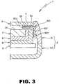
- the display screen protection cover 9 is mounted by using the double-sided adhesive tape T as shown in FIG. 2 and Fig. 3 .
- the rigidity at the periphery of the viewing window 3o is greatly improved by integrally fixing the reinforcing frame 100 having a frame shape to the upper inner casing 3I, and thus, even when the display screen protection cover 9 is pressed from the outside, the mobile phone I will not be easily deflected or deformed at the periphery of the viewing window 3o of the upper inner casing 3I.
- the display screen protection cover 9 is mounted to the front plate 101 of the reinforcing frame 100.
- the reinforcing frame 100 which has a great mechanical strength, positively supports the external force, which results in no undesired deformation being produced in the upper inner casing 3I.
- the flexibility of the plastic material used for the upper cabinet 3 is retained in the areas other than the periphery of the viewing window 3o in the upper inner casing 3I, where the rigidity is greatly improved by fixing the reinforcing frame 100 having a frame shape. Therefore, even when the upper cabinet 3 is dropped, for example, and subjected to a great impact force, the impact force will be attenuated by the flexibility of the upper cabinet 3 made of a plastic material, and thus will not directly act on the liquid crystal display device 7. As a result, damage to the liquid crystal display device 7 and the plastic material portion itself of the equipment cabinet can be prevented.
- the reinforcing frame 100 is adapted to provide a box-like shape with the front plate 101 and with the side plates 102 on all the sides. Specifically, the reinforcing frame has a box-like shape with four corners, each of which is formed by the front plate 101 and the adjacent side plates 102, 102.
- the rigidity of the reinforcing frame 100 itself is greatly increased, which results in the rigidity of the upper inner casing 3I where the reinforcing frame 100 is fixed being substantially improved. Therefore, damage to the liquid crystal display device 7 when the display screen protection cover 9 is pressed from the outside being extremely effectively prevented.
- the display screen protection cover 9 is mounted to the upper inner casing 3I where the reinforcing frame 100 is fixed.
- the upper inner casing 3I, the reinforcing frame 100, and the display screen protection cover 9 are handled as a single component, i.e., a casing assembly.
- the circuit board 5 loaded with the liquid crystal display device 7 is mounted to the casing assembly, specifically, the upper inner casing 3I by using screws S, and then the upper outer casing 30 is assembled to the upper inner casing 3I.
- the assembling operation can be performed extremely simply by handling the upper inner casing 3I, the reinforcing frame 100, and the display screen protection cover 9 as a casing assembly or a single component, which allows substantial increase in the production efficiency to be achieved.
- FIG. 7 to FIG. 12 show a second embodiment where a liquid crystal display device protection structure relating to the present invention is applied to a mobile phone, which is a type of electronic equipment.
- An upper cabinet (equipment cabinet) 13 in the foldable mobile phone 10 comprises an upper inner casing 131 and an upper outer casing 130 which are assembled to each other, and the upper inner casing 13I and the upper outer casing 130 are both manufactured in a desired shape by injection molding of plastic material.
- a circuit board 15 is accommodated in the inside of the upper cabinet 13, and on the component mounting surface of the circuit board 15, a backlight device 16 and a liquid crystal display device 17 constituting a liquid crystal display unit are mounted in a prescribed location through a holder 18.
- a viewing window 13o which is faced with the display screen 17f of the liquid crystal display device 17.
- a display screen protection cover 19 made of a light transmitting material, such as a clear acrylic plastic material, with the use of a double-sided adhesive tape T (see FIG. 9 ).
- the viewing window 13o in the upper inner casing 13I is covered with the display screen protection cover 19.
- a reinforcing frame 110 having a frame shape which is matched to the periphery of the viewing window 13o is integrally fixed to the upper inner casing 13I, the reinforcing frame 110 being formed by press working (drawing forming) of a material with a mechanical strength higher than that of the plastic material used for the upper inner casing 13I and the like, specifically, of a stainless steel sheet.
- the reinforcing frame 110 has a front plate 111 which is developed so as to be matched to the display screen 17f of the liquid crystal display device 17, and also has side plates 112 on all the sides that surround the liquid crystal display device 17, being developed from the outer edge of the front plate 111 in the direction along the plate thickness, specifically, towards the inside of the upper inner casing 13I, and being formed over the entire periphery of the front plate 111.
- an opening 111o for exposing the display screen 17f of the liquid crystal display device 17 is formed.
- a rib 112r is formed over the entire periphery.
- two tabs 113 each having a mounting hole 113o are formed as being protruded (thus four tabs are formed in total).
- the reinforcing frame 110 comprising the front plate 111 having the opening 111o and the side plates 112 on all the sides provides a frame shape which is matched to the periphery of the viewing window 13o, and also provides a box-like shape having four corners each of which is formed by the front plate 111 and the adjacent side plates 112, 112.
- the reinforcing frame 110 is integrally fixed in the prescribed location in the upper inner casing 13I.
- the front plate 111 of the reinforcing frame 110 which is fixed to the upper inner casing 13I is exposed in the viewing window 13o in the upper inner casing 13I, and to the front plate 111 (the reinforcing frame 110), the display screen protection cover 19 is mounted by using the double-sided adhesive tape T.
- the outline size can be minimized while damage to the liquid crystal display device 17 can be prevented, in completely the same manner as with the mobile phone 1 in the first embodiment described above in detail, even when the display screen protection cover 19 is pressed from the outside, or when the upper cabinet 13 is dropped, for example, and subjected to a great impact force.
- the display screen protection cover 19 is mounted to the upper inner casing 13I where the reinforcing frame 110 is fixed as shown in FIG. 10 .
- the upper inner casing 13I, the reinforcing frame 110, and the display screen protection cover 19 are handled as a single component, i.e., a casing assembly.
- the circuit board 15 loaded with the liquid crystal display device 17 is mounted to the casing assembly, specifically, the upper inner casing 13I by using screws S.
- the upper outer casing 130 is assembled to the upper inner casing 13I. Therefore, the assembling operation can be performed extremely simply, and a substantial increase in the production efficiency can be achieved.
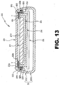
- FIG. 13 to FIG. 18 show a third embodiment where a liquid crystal display device protection structure relating to the present invention is applied to a mobile phone, which is a type of electronic equipment.
- An upper cabinet (equipment cabinet) 23 in this foldable mobile phone 20 comprises an upper inner casing 23I and an upper outer casing 230 which are assembled to each other.
- the upper inner casing 23I and the upper outer casing 230 are both manufactured in a desired shape by injection molding of plastic material.
- a circuit board 25 is accommodated in the inside of the upper cabinet 23.
- a backlight device 26 and a liquid crystal display device 27 constituting a liquid crystal display unit are mounted in a prescribed location through a holder 28.
- a viewing window 23o which is faced with the display screen 27f of the liquid crystal display device 27.
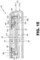
- a display screen protection cover 29 made of a light transmitting material, such as a clear acrylic plastic material, with the use of a double-sided adhesive tape T (see FIG. 15 ).
- the viewing window 23o in the upper inner casing 23I is covered with the display screen protection cover 29.
- a reinforcing frame 120 having a frame shape which is matched to the periphery of the viewing window 23o is integrally fixed to the upper inner casing 23I.
- the reinforcing frame 120 is formed by press working (drawing forming) of a material with a mechanical strength higher than that of the plastic material used for the upper inner casing 23I and the like, specifically, of a stainless steel sheet.
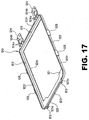
- the reinforcing frame 120 has a front plate 121 which is developed so as to be matched to the display screen 27f of the liquid crystal display device 27.
- the reinforcing frame 120 also has side plates 122 on all the sides that surround the liquid crystal display device 27.
- the side plates 122 are developed from the outer edge of the front plate 121 in the direction along the plate thickness, specifically, towards the inside of the upper inner casing 23I, and are formed over the entire periphery of the front plate 121.
- an opening 121o for exposing the display screen 27f of the liquid crystal display device 27 is formed.
- a rib 122r is formed over the entire periphery.
- the reinforcing frame 120 comprising the front plate 121 having the opening 121o and the side plates 122 arranged on all the sides thereof provides a frame shape which is matched to the periphery of the viewing window 23o.
- the front plate 121 also provides a box-like shape having four corners each of which is formed by the front plate 121 and the adjacent side plates 122, 122.
- two tabs 123 each having a mounting hole 123o are formed to be protruded.
- two tabs 124 each having a mounting hole 124o and a screw hole 124h are formed as being protruded.
- two hooks 125 are formed to be protruded toward the outside (thus four hooks are formed in total).
- the reinforcing frame 120 is integrally fixed in the prescribed location in the upper inner casing 23I.
- the tabs 124 of the reinforcing frame 120 are tightened to both the extension 28a (see FIG. 15 and FIG. 18 ) of the holder 28 and the upper inner casing 23I by means of the screws S which are penetrated through the screw holes 124h, thereby the portions of the upper inner casing 23I and the circuit board 25 that are poor in strength are connected to the reinforcing frame 120 to be effectively reinforced.
- the front plate 121 of the reinforcing frame 120 which is fixed to the upper inner casing 23I is exposed in the viewing window 23o in the upper inner casing 23I.
- the display screen protection cover 29 is mounted by using the double-sided adhesive tape T.
- the outline size can be minimized while damage to the liquid crystal display device 27 can be prevented in completely the same manner as in the first embodiment and the second embodiment described above, when a great impact force is applied such as when the display screen protection cover 29 is pressed from the outside, or when the upper cabinet 23 is dropped.
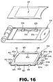
- the display screen protection cover 29 is mounted to the upper inner casing 23I where the reinforcing frame 120 is fixed as shown in FIG. 18 .
- the upper inner casing 23I, the reinforcing frame 120, and the display screen protection cover 29 are handled as a single component, i.e., a casing assembly.
- the circuit board 25 loaded with the liquid crystal display device 27 is mounted to the casing assembly, specifically, the upper inner casing 23I by using screws S, and then the upper outer casing 230 is assembled to the upper inner casing 23I. Therefore, the assembling operation can be performed extremely simply, and a substantial increase in the production efficiency can be achieved.
- the reinforcing frame is formed by drawing forming a stainless steel sheet.
- appropriate metallic materials other than stainless steel may be used for formation of the reinforcing frame, if it has a mechanical strength higher than that of the plastic material used for the upper inner casing and the like.
- appropriate methods of forming other than drawing may be used for formation of the reinforcing frame.
- the liquid crystal display device can be prevented from being broken down due to the static electricity applied from the outside.
- such reinforcing frame may be used as an antenna.
- the reinforcing frame can, of course, be fixed to the upper inner casing by using a double-sided adhesive tape, an adhesive, or any other appropriate means which are not mentioned in the embodiments.
- an adhesive, screws, or any appropriate means other than the double-sided tape that is mentioned in the embodiments, may be adopted.
- the present invention is applied to a mobile phone, which is a type of electronic equipment.
- the present invention can also be applied, as an extremely effective liquid crystal display protection structure, to communication equipment such as a portable telephone and a PHS (personal handyphone system), portable information terminals such as an electronic dictionary and a PDA (personal data assistance), and other various types of electronic equipment having a liquid crystal display device.
- communication equipment such as a portable telephone and a PHS (personal handyphone system), portable information terminals such as an electronic dictionary and a PDA (personal data assistance), and other various types of electronic equipment having a liquid crystal display device.
Landscapes
- Engineering & Computer Science (AREA)
- Physics & Mathematics (AREA)
- Theoretical Computer Science (AREA)
- General Physics & Mathematics (AREA)
- Computer Hardware Design (AREA)
- Human Computer Interaction (AREA)
- General Engineering & Computer Science (AREA)
- Mathematical Physics (AREA)
- Nonlinear Science (AREA)
- Chemical & Material Sciences (AREA)
- Crystallography & Structural Chemistry (AREA)
- Optics & Photonics (AREA)
- Devices For Indicating Variable Information By Combining Individual Elements (AREA)
- Liquid Crystal (AREA)
Description
- This application is based upon and claims the benefit of priority from the prior Japanese Patent Application No.
2004-190025 filed on June 28, 2004 - The present invention relates to a liquid crystal display device protection structure for electronic equipment, and specifically, to a protection structure for preventing the damage to the liquid crystal display device, which can be applied to electronic equipment including a liquid crystal display device accommodated in the inside of an equipment cabinet made of a plastic material, a viewing window which is faced with the display screen of the liquid crystal display device and is formed in the equipment cabinet, and a display screen protection cover which covers the viewing window.
- In a mobile phone, which is a type of electronic equipment, a liquid crystal display device for informing a variety of information to the user by means of characters and images is mounted. In a foldable mobile phone A as shown in
FIG. 19 and FIG. 20 , a liquid crystal display device E is accommodated in the inside of an upper cabinet D which is connected to a lower cabinet B having a variety of controllers by means of a hinge C. - The liquid crystal display device E together with a backlight device G is mounted, through a holder H, on a circuit board F disposed in the upper cabinet D that comprises an upper inner casing Da and an upper outer casing Db. In the upper inner casing Da, a viewing window Do which is faced with the display screen Ef of the liquid crystal display device E is formed. In the viewing window Do, a display screen protection cover I made of a light transmitting material is mounted.
- In general electronic equipment, the equipment cabinet is made of a plastic material for the purposes of reduction in weight, etc. With the mobile phone A described above in which a large viewing window Do is formed in the upper inner casing Da, the upper inner casing Da is likely to be deflected or deformed relatively easily when the display screen protection cover I is heavily depressed from the outside, which may cause the display screen protection cover I to be brought into contact with the liquid crystal display device E, resulting in that damages such as cracks are created in the display device E.
- Possible solutions to such a problem are to increase the wall thickness of the upper cabinet D including that of the upper inner casing Da thereby enhancing the strength, or to increase the clearance between the display screen Ef of the liquid crystal display device E and the display screen protection cover I. However, these solutions inevitably cause another problem of an undesired increase in the size of the mobile phone A.
- On the other hand, a solution which increases the mechanical strength of the equipment cabinet has been proposed in which the equipment cabinet made of a plastic material is integrally molded with the reinforcing member made of a metallic material.
- Specifically, as shown in
FIG. 21 , an upper inner casing Da' accommodates, together with an upper outer casing Db', a liquid crystal display device E' which is loaded on a circuit board F' through a holder H'. A display screen protection cover I' is mounted in a viewing window Do' of the upper inner casing Da' and a pair of hinges C' are provided at the base side end of the upper inner casing Da'. Further, the upper inner casing Da' is integrally molded with a reinforcing member J as shown inFIG. 22 in the injection molding. - The reinforcing member J has a top plate Ja in which an opening Jo is formed corresponding to the viewing window Do' in the upper inner casing Da'. A pair of side plates Jb are erected from the right and left edges of the top plate Ja, and a pair of bearing members Jc which have a cylindrical shape are formed at the base side end of the top plate Ja.
- According to this configuration, the mechanical strength of the upper inner casing Da' is greatly improved because it is integrally formed with the reinforcing member J. With this configuration, even if the display screen protection cover I' is heavily pressed from the outside, the upper inner casing Da' will not be easily deflected or deformed. Thus, damage to the liquid crystal display device E' due to the contact with the display screen protection cover I' can be prevented.
- However, with the configuration as described above, although the mechanical strength of the upper inner casing Da' is improved, the reinforcing member J occupies a significantly large portion of the inside of the upper inner casing Da' as shown in
FIG. 23 . Therefore, the size of the outline shape is inevitably increased. - Further, with the configuration as described above, the top plate Ja, the right and left side plates Jb, and the pair of bearing members Jc are provided, thus the reinforcing member J is integrally insert molded with the upper inner casing Da' over the entire area of the upper inner casing Da', which results in an increase in the rigidity of the upper inner casing Da' as a whole, which leads to an increase in the rigidity of the upper cabinet including the upper inner casing Da'.
- Therefore, even if the display screen protection cover I' is heavily pressed from the outside, damage to the liquid crystal display device E' can be prevented. However, because the upper cabinet has a high rigidity and lacks the flexibility as stated above, when the upper cabinet is subjected to a great impact force due to such a cause as dropping, the impact force is neither absorbed nor attenuated by the upper cabinet, but directly acts on the liquid crystal display device E'. As a result, the liquid crystal display device E', which comprises a glass substrate, and the plastic material portion itself of the equipment cabinet may be cracked or otherwise damaged.
-
JP 2003 258446 A -
WO 03/040906 A1 EP 1 443 386 A1 disclose a touch panel assembly having a housing frame that supports components of a front light unit in an integral manner but no reinforcement member. To attenuate deformation of the touch panel, a transparent buffer member is disposed between the touch panel and a light conductor plate so that the touch panel does not contact and damage the light conductor plate. - The present invention has been made in view of the above-mentioned problems, and may provide a liquid crystal display device protection structure for electronic equipment that allows the outline size to be minimized while preventing damage to the liquid crystal display device.
- According to a first aspect of the invention, a liquid crystal display device protection structure for electronic equipment having an equipment cabinet made of a plastic material in which a liquid crystal display device is accommodated, the equipment cabinet formed with a viewing window so as to be faced with a display screen of the liquid crystal display device, comprises a display screen protection cover which covers the viewing window; and a reinforcing frame made of a material having a mechanical strength higher than that of the plastic material used for the equipment cabinet, and having a frame shape matched to a periphery of the viewing window, the reinforcing frame being integrally fixed to the equipment cabinet so as to be matched to the periphery of the viewing window, wherein the display screen protection cover is mounted to the reinforcing frame.
- With this configuration of the liquid crystal display device protection structure for electronic equipment according to the first aspect of the invention, the rigidity at the periphery of the viewing window is greatly improved by integrally fixing the reinforcing frame having a frame shape to the equipment cabinet, and thus, even when the display screen protection cover is pressed from the outside, the equipment will not be easily deflected or deformed at the periphery of the viewing window of the equipment cabinet, which allows damage to the liquid crystal display device to be prevented without increasing the outline size by increasing the wall thickness of the equipment cabinet or otherwise changing the configuration.
- In addition, the liquid crystal display device protection structure for electronic equipment according to the first aspect of the invention, the flexibility of the plastic material used for the equipment cabinet is retained in the areas other than the periphery of the viewing window in the equipment cabinet, where the rigidity is greatly improved by fixing the reinforcing frame having a frame shape. Therefore, even when the equipment cabinet is dropped, for example, and subjected to a great impact force, the impact force will be attenuated by the flexibility of the equipment cabinet made of a plastic material, and thus will not directly act on the liquid crystal display device, which allows preventing of damage to the liquid crystal display device.
- Thus, with the liquid crystal display device protection structure for electronic equipment according to the first aspect of the present invention, the outline size can be minimized while damage to the liquid crystal display device can be prevented, even when the display screen protection cover is pressed from the outside, or when the equipment cabinet is dropped, for example, and subjected to an impact force.
- A liquid crystal display device protection structure for electronic equipment according to the present invention provides a liquid crystal display device protection structure for electronic equipment according to the first aspect of the present invention, wherein the reinforcing frame has a box-like shape, and comprises a front plate that is developed so as to be matched to the display screen of the liquid crystal display device, and has an opening for exposing the display screen; and side plates that are developed from an outer edge of the front plate to a direction along thickness of the front plate so as to surround an entire periphery of the liquid crystal display device.
- With this configuration of the liquid crystal display device protection structure for electronic equipment according to the second aspect of the present invention, the outline size can be minimized while damage to the liquid crystal display device can be prevented, as with the liquid crystal display device protection structure for electronic equipment relating to the invention as set forth in claim 1, and because the reinforcing frame is adapted to provide a box-like shape with the front plate and the side plates, the rigidity of the reinforcing frame itself is improved, with the rigidity at the periphery of the viewing window in the equipment cabinet where the reinforcing frame is integrally fixed being greatly improved; therefore the effect of prevention of the liquid crystal display device from being damaged when the display screen protection cover is pressed from the outside is substantially enhanced.
- A liquid crystal display device protection structure for electronic equipment according to a third aspect of the present invention provides a liquid crystal display device protection structure for electronic equipment according to the second aspect of the present invention, wherein the reinforcing frame has four corners each of which is formed by the front plate and the side plates which are adjacent to each other, and the front plate and the side plates which are adjacent to each other are connected to one another.
- With this configuration of the liquid crystal display device protection structure for electronic equipment according to the third aspect of the present invention, the front plate and the side plates adjacent to each other which form each of the four corners are connected to one another, which results in the rigidity of the reinforcing frame itself being substantially improved, with the rigidity at the periphery of the viewing window in the equipment cabinet where the reinforcing frame is integrally fixed being greatly improved; therefore the effect of prevention of the liquid crystal display device from being damaged when the display screen protection cover is pressed from the outside is substantially enhanced.
- A liquid crystal display device protection structure for electronic equipment according to a fourth aspect of the present invention, a liquid crystal display device protection structure for electronic equipment according to the first aspect of the present invention, wherein the reinforcing frame is integrally fixed to the equipment cabinet by insert molding of the reinforcing frame to the equipment cabinet.
- With this configuration of the liquid crystal display device protection structure for electronic equipment according to the fourth aspect of the present invention, the reinforcing frame is integrally fixed to the equipment cabinet by insert molding; therefore, the reinforcing frame can be extremely easily fixed to the equipment cabinet.
- A liquid crystal display device protection structure for electronic equipment according to a fifth aspect of the present invention provides a liquid crystal display device protection structure for electronic equipment according to the first aspect of the present invention, wherein, by hooking the reinforcing frame to claws provided for the equipment cabinet, the reinforcing frame is integrally fixed to the equipment cabinet.
- With the liquid crystal display device protection structure for electronic equipment according to the fifth aspect of the present invention, the reinforcing frame is integrally fixed to the equipment cabinet by hooking the reinforcing frame to claws provided for the equipment cabinet; therefore, the reinforcing frame can be extremely easily fixed to the equipment cabinet.
- A liquid crystal display device protection structure for electronic equipment according to a sixth aspect of the present invention provides a liquid crystal display device protection structure for electronic equipment according to the first aspect of the present invention, wherein, by welding the reinforcing frame to the equipment cabinet, the reinforcing frame is integrally fixed to the equipment cabinet.
- With this configuration of the liquid crystal display device protection structure for electronic equipment according to the sixth aspect of the present invention, the reinforcing frame is integrally fixed to the equipment cabinet by welding; therefore, the reinforcing frame can be extremely easily fixed to the equipment cabinet.
- A liquid crystal display device protection structure for electronic equipment according to a seventh aspect of the present invention provides a liquid crystal display device protection structure for electronic equipment according to the first aspect of the present invention, wherein, by using screws for fixing the reinforcing frame to the equipment cabinet, the reinforcing frame is integrally fixed to the equipment cabinet.
- With this configuration of the liquid crystal display device protection structure for electronic equipment according to the seventh aspect of the present invention, the reinforcing frame is integrally fixed to the equipment cabinet by using screws; therefore, the reinforcing frame can be extremely easily fixed to the equipment cabinet.
- A liquid crystal display device protection structure for electronic equipment according to an eighth aspect of the present invention provides a liquid crystal display device protection structure for electronic equipment according to the first aspect of the present invention, wherein, by hooking hooks provided for the reinforcing frame to the equipment cabinet, the reinforcing frame is integrally fixed to the equipment cabinet.
- With this configuration of the liquid crystal display device protection structure for electronic equipment according to the eighth aspect of the present invention, the reinforcing frame is integrally fixed to the equipment cabinet by hooking hooks provided for the reinforcing frame to the equipment cabinet; therefore, the reinforcing frame can be extremely easily fixed to the equipment cabinet.
- Embodiments of the present invention will be described in detail based on the following figures, wherein:
-
FIG. 1 is an appearance perspective view showing a first embodiment of electronic equipment which adopts a liquid crystal display device protection structure relating to the present invention; -
FIG. 2 is a transverse cross section showing the electronic equipment of the first embodiment; -
FIG. 3 is a main portion enlarged sectional view showing the electronic equipment of the first embodiment; -
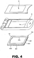
FIG. 4 is an exploded perspective view showing an upper inner casing assembly in the electronic equipment of the first embodiment; -
FIG. 5 is an appearance perspective view showing a reinforcing frame in the electronic equipment of the first embodiment; -
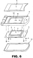
FIG. 6 is an exploded perspective view showing the electronic equipment of the first embodiment; -
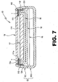
FIG. 7 is a transverse cross section showing a second embodiment of electronic equipment which adopts a liquid crystal display device protection structure relating to the present invention; -
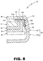
FIG. 8 is a main portion enlarged sectional view showing electronic equipment of the second embodiment; -
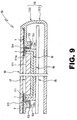
FIG. 9 is a longitudinal section showing electronic equipment of the second embodiment; -
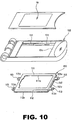
FIG. 10 is an exploded perspective view showing an upper inner casing assembly in electronic equipment of the second embodiment; -
FIG. 11 is an appearance perspective view showing a reinforcing frame in electronic equipment of the second embodiment; -
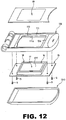
FIG. 12 is an exploded perspective view showing electronic equipment of the second embodiment; -
FIG. 13 is a transverse cross section showing a third embodiment of electronic equipment which adopts a liquid crystal display device protection structure relating to the present invention; -
FIG. 14A and FIG. 14B are main portion enlarged sectional views showing electronic equipment of the third embodiment; -
FIG. 15 is a longitudinal section showing electronic equipment of the third embodiment; -
FIG. 16 is an exploded perspective view showing an upper inner casing assembly in electronic equipment of the third embodiment; -
FIG. 17 is an appearance perspective view showing a reinforcing frame in electronic equipment of the third embodiment; -
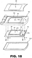
FIG. 18 is an exploded perspective view showing electronic equipment of the third embodiment; -
FIG. 19 is an appearance perspective view showing an example of conventional electronic equipment; -
FIG. 20 is a schematic transverse cross section showing the conventional electronic equipment as shown inFIG. 19 ; -
FIG. 21 is an exploded perspective view showing another conventional electronic equipment; -
FIG. 22 is an appearance perspective view showing a reinforcing member in the conventional electronic equipment as shown inFIG. 21 ; and -
FIG. 23 is a schematic transverse cross section showing the conventional electronic equipment as shown inFIG. 21 ; - Embodiments of the present invention will be described with reference to the accompanying drawings.
-
FIG. 1 through FIG. 6 show a first embodiment where a liquid crystal display device protection structure relating to the present invention is applied to a foldable mobile phone, which is a type of electronic equipment. This mobile phone 1 comprises alower cabinet 2 provided with a variety of controllers, and anupper cabinet 3 accommodating a liquidcrystal display device 7 later described. Thelower cabinet 2 and theupper cabinet 3 are connected to each other through a hinge 4 such that the foldable mobile phone can be freely opened and closed. - The
upper cabinet 3, which constitutes the equipment cabinet together with thelower cabinet 2, comprises an upper inner casing 3I and an upperouter casing 30 which are assembled to each other, and the upper inner casing 3I and the upperouter casing 30 are both manufactured in a desired shape by injection molding of plastic material. - As shown in
FIG. 2 andFIG. 3 , acircuit board 5 is accommodated in the inside of theupper cabinet 3, and on the component mounting surface of thecircuit board 5, a backlight device6 and a liquidcrystal display device 7 constituting a liquid crystal display unit are mounted in a prescribed location through aholder 8. - In the upper inner casing 3I in the
upper cabinet 3 is formed a viewing window 3o which is faced with thedisplay screen 7f of the liquidcrystal display device 7. To the front of the inner casing 3I is mounted a displayscreen protection cover 9 made of a light transmitting material, such as a clear acrylic plastic material, with the use of a double-sided adhesive tape (not shown), the viewing window 3o in the upper inner casing 3I being covered with the displayscreen protection cover 9. - Further, in the upper inner casing 3I of the
upper cabinet 3, a reinforcingframe 100 having a frame shape which is matched to the periphery of the viewing window 3o is integrally fixed to the upper inner casing 3I. The reinforcingframe 100 is formed by press working (drawing operation) of a material with a mechanical strength higher than that of the plastic material used for the upper inner casing 3I and the like. Specifically, the reinforcingframe 100 may be formed of a stainless steel sheet. - As shown in
FIG. 4 andFIG. 5 , the reinforcingframe 100 has afront plate 101 which is developed so as to be matched to thedisplay screen 7f of the liquidcrystal display device 7. The reinforcingframe 100 further hasside plates 102 on all the sides that surround the liquidcrystal display device 7. Theside plates 102 are developed from the outer edge of thefront plate 101 in the direction along the plate thickness, specifically, towards the inside of the upper inner casing 3I, and are formed over the entire periphery of thefront plate 101. - In the
front plate 101 of the reinforcingframe 100, an opening 101o for exposing thedisplay screen 7f of the liquidcrystal display device 7 is formed. At the edges of theside plates 102 on all the sides, arib 102r is formed over the entire periphery. - As stated above, the reinforcing
frame 100 comprising thefront plate 101 having the opening 101o and theside plates 102 on all the sides thereof has a frame shape which is matched to the periphery of the viewing window 3o, and also has a box-like shape having four corners each of which is formed by thefront plate 101 and theadjacent side plates 102. - Further, the reinforcing
frame 100 is integrally fixed to the upper inner casing 3I by insert molding when the upper inner casing 3I is injection molded. - As shown in
FIG. 2 andFIG. 6 , thefront plate 101 of the reinforcingframe 100 which is fixed to the upper inner casing 3I is exposed in the viewing window 3o in the upper inner casing 3I. To the front plate 101 (the reinforcing frame 100), the displayscreen protection cover 9 is mounted by using the double-sided adhesive tape T as shown inFIG. 2 andFig. 3 . - With the mobile phone 1 which adopts the liquid crystal display device protection structure as stated above, the rigidity at the periphery of the viewing window 3o is greatly improved by integrally fixing the reinforcing
frame 100 having a frame shape to the upper inner casing 3I, and thus, even when the displayscreen protection cover 9 is pressed from the outside, the mobile phone I will not be easily deflected or deformed at the periphery of the viewing window 3o of the upper inner casing 3I. - In addition, the display
screen protection cover 9 is mounted to thefront plate 101 of the reinforcingframe 100. Thus, even when the displayscreen protection cover 9 is pressed from the outside, the reinforcingframe 100, which has a great mechanical strength, positively supports the external force, which results in no undesired deformation being produced in the upper inner casing 3I. - Therefore, without the need for increasing the wall thickness of the
upper cabinet 3 including the upper inner casing 3I to enhance the strength, or for widening the clearance between thedisplay screen 7f of the liquidcrystal display device 7 and the displayscreen protection cover 9, in other words, without any undesired increase in the size of the mobile phone 1 being caused, damage to the liquidcrystal display device 7 can be prevented. - In addition, with the mobile phone 1 which adopts the liquid crystal display device protection structure as stated above, the flexibility of the plastic material used for the
upper cabinet 3 is retained in the areas other than the periphery of the viewing window 3o in the upper inner casing 3I, where the rigidity is greatly improved by fixing the reinforcingframe 100 having a frame shape. Therefore, even when theupper cabinet 3 is dropped, for example, and subjected to a great impact force, the impact force will be attenuated by the flexibility of theupper cabinet 3 made of a plastic material, and thus will not directly act on the liquidcrystal display device 7. As a result, damage to the liquidcrystal display device 7 and the plastic material portion itself of the equipment cabinet can be prevented. - Further, with the mobile phone 1 which adopts the liquid crystal display device protection structure as stated above, the reinforcing
frame 100 is adapted to provide a box-like shape with thefront plate 101 and with theside plates 102 on all the sides. Specifically, the reinforcing frame has a box-like shape with four corners, each of which is formed by thefront plate 101 and theadjacent side plates frame 100 itself is greatly increased, which results in the rigidity of the upper inner casing 3I where the reinforcingframe 100 is fixed being substantially improved. Therefore, damage to the liquidcrystal display device 7 when the displayscreen protection cover 9 is pressed from the outside being extremely effectively prevented. - Referring to
FIG. 6 , to assemble the mobile phone 1 having a configuration as stated above, the displayscreen protection cover 9 is mounted to the upper inner casing 3I where the reinforcingframe 100 is fixed. Thus, the upper inner casing 3I, the reinforcingframe 100, and the displayscreen protection cover 9 are handled as a single component, i.e., a casing assembly. Thecircuit board 5 loaded with the liquidcrystal display device 7 is mounted to the casing assembly, specifically, the upper inner casing 3I by using screws S, and then the upperouter casing 30 is assembled to the upper inner casing 3I. - With the mobile phone 1 which adopts the liquid crystal display device protection structure as stated above, the assembling operation can be performed extremely simply by handling the upper inner casing 3I, the reinforcing
frame 100, and the displayscreen protection cover 9 as a casing assembly or a single component, which allows substantial increase in the production efficiency to be achieved. -
FIG. 7 to FIG. 12 show a second embodiment where a liquid crystal display device protection structure relating to the present invention is applied to a mobile phone, which is a type of electronic equipment. An upper cabinet (equipment cabinet) 13 in the foldablemobile phone 10 comprises an upperinner casing 131 and an upperouter casing 130 which are assembled to each other, and the upperinner casing 13I and the upperouter casing 130 are both manufactured in a desired shape by injection molding of plastic material. - As shown in
FIG. 7 to FIG. 9 , acircuit board 15 is accommodated in the inside of theupper cabinet 13, and on the component mounting surface of thecircuit board 15, abacklight device 16 and a liquidcrystal display device 17 constituting a liquid crystal display unit are mounted in a prescribed location through aholder 18. - In the upper
inner casing 131 of theupper cabinet 13 is formed a viewing window 13o which is faced with thedisplay screen 17f of the liquidcrystal display device 17. To the front of theinner casing 13I is mounted a displayscreen protection cover 19 made of a light transmitting material, such as a clear acrylic plastic material, with the use of a double-sided adhesive tape T (seeFIG. 9 ). The viewing window 13o in the upperinner casing 13I is covered with the displayscreen protection cover 19. - Further, in the upper
inner casing 13I of theupper cabinet 13, a reinforcingframe 110 having a frame shape which is matched to the periphery of the viewing window 13o is integrally fixed to the upperinner casing 13I, the reinforcingframe 110 being formed by press working (drawing forming) of a material with a mechanical strength higher than that of the plastic material used for the upperinner casing 13I and the like, specifically, of a stainless steel sheet. - As shown in
FIG. 10 andFIG. 11 , the reinforcingframe 110 has afront plate 111 which is developed so as to be matched to thedisplay screen 17f of the liquidcrystal display device 17, and also hasside plates 112 on all the sides that surround the liquidcrystal display device 17, being developed from the outer edge of thefront plate 111 in the direction along the plate thickness, specifically, towards the inside of the upperinner casing 13I, and being formed over the entire periphery of thefront plate 111. - In the
front plate 111 of the reinforcingframe 110, an opening 111o for exposing thedisplay screen 17f of the liquidcrystal display device 17 is formed. At the edges of theside plates 112 on all the sides, arib 112r is formed over the entire periphery. On each of a pair ofside plates tabs 113 each having a mounting hole 113o are formed as being protruded (thus four tabs are formed in total). - As stated above, the reinforcing
frame 110 comprising thefront plate 111 having the opening 111o and theside plates 112 on all the sides provides a frame shape which is matched to the periphery of the viewing window 13o, and also provides a box-like shape having four corners each of which is formed by thefront plate 111 and theadjacent side plates - As shown in
FIG. 7 ,FIG. 9 , andFIG. 10 , in the inside of the upperinner casing 13I, four hookingclaws 13t are formed inside the side walls which are opposed to each other, and four mountingpins 13p are formed to be protruded inside the front wall, sandwiching the viewing window 13o. By hooking theribs 112r of the reinforcingframe 110 to the respective hookingclaws 13t, and heating and pressing the head of the mountingpin 13p that is inserted into the mounting hole 113o in therespective tabs 113 for upsetting and welding it, the reinforcingframe 110 is integrally fixed in the prescribed location in the upperinner casing 13I. - As shown in
FIG. 7 to FIG. 9 , andFIG. 12 , thefront plate 111 of the reinforcingframe 110 which is fixed to the upperinner casing 13I is exposed in the viewing window 13o in the upperinner casing 13I, and to the front plate 111 (the reinforcing frame 110), the displayscreen protection cover 19 is mounted by using the double-sided adhesive tape T. - Also with the
mobile phone 10 which adopts the liquid crystal display device protection structure as stated above, the outline size can be minimized while damage to the liquidcrystal display device 17 can be prevented, in completely the same manner as with the mobile phone 1 in the first embodiment described above in detail, even when the displayscreen protection cover 19 is pressed from the outside, or when theupper cabinet 13 is dropped, for example, and subjected to a great impact force. - When the
mobile phone 10 having a configuration as stated above is assembled, the displayscreen protection cover 19 is mounted to the upperinner casing 13I where the reinforcingframe 110 is fixed as shown inFIG. 10 . The upperinner casing 13I, the reinforcingframe 110, and the displayscreen protection cover 19 are handled as a single component, i.e., a casing assembly. Thecircuit board 15 loaded with the liquidcrystal display device 17 is mounted to the casing assembly, specifically, the upperinner casing 13I by using screws S. Then the upperouter casing 130 is assembled to the upperinner casing 13I. Therefore, the assembling operation can be performed extremely simply, and a substantial increase in the production efficiency can be achieved. -
FIG. 13 to FIG. 18 show a third embodiment where a liquid crystal display device protection structure relating to the present invention is applied to a mobile phone, which is a type of electronic equipment. An upper cabinet (equipment cabinet) 23 in this foldablemobile phone 20 comprises an upper inner casing 23I and an upperouter casing 230 which are assembled to each other. The upper inner casing 23I and the upperouter casing 230 are both manufactured in a desired shape by injection molding of plastic material. - As shown in
FIG. 13 to FIG. 15 , acircuit board 25 is accommodated in the inside of theupper cabinet 23. On the component mounting surface of thecircuit board 25, abacklight device 26 and a liquidcrystal display device 27 constituting a liquid crystal display unit are mounted in a prescribed location through aholder 28. - In the upper inner casing 23I of the
upper cabinet 23 is formed a viewing window 23o which is faced with thedisplay screen 27f of the liquidcrystal display device 27. To the front of the inner casing 23I is mounted a displayscreen protection cover 29 made of a light transmitting material, such as a clear acrylic plastic material, with the use of a double-sided adhesive tape T (seeFIG. 15 ). The viewing window 23o in the upper inner casing 23I is covered with the displayscreen protection cover 29. - Further, in the upper inner casing 23I of the
upper cabinet 23, a reinforcingframe 120 having a frame shape which is matched to the periphery of the viewing window 23o is integrally fixed to the upper inner casing 23I. The reinforcingframe 120 is formed by press working (drawing forming) of a material with a mechanical strength higher than that of the plastic material used for the upper inner casing 23I and the like, specifically, of a stainless steel sheet. - As shown in
FIG. 16 andFIG. 17 , the reinforcingframe 120 has afront plate 121 which is developed so as to be matched to thedisplay screen 27f of the liquidcrystal display device 27. The reinforcingframe 120 also hasside plates 122 on all the sides that surround the liquidcrystal display device 27. Theside plates 122 are developed from the outer edge of thefront plate 121 in the direction along the plate thickness, specifically, towards the inside of the upper inner casing 23I, and are formed over the entire periphery of thefront plate 121. - In the
front plate 121 of the reinforcingframe 120, an opening 121o for exposing thedisplay screen 27f of the liquidcrystal display device 27 is formed. At the edges of theside plates 122 on all the sides, arib 122r is formed over the entire periphery. - The reinforcing
frame 120 comprising thefront plate 121 having the opening 121o and theside plates 122 arranged on all the sides thereof provides a frame shape which is matched to the periphery of the viewing window 23o. Thefront plate 121 also provides a box-like shape having four corners each of which is formed by thefront plate 121 and theadjacent side plates - On one
side plate 122 in the longitudinal direction of the reinforcingframe 120, twotabs 123 each having a mounting hole 123o are formed to be protruded. On theother side plate 122 in the longitudinal direction of the reinforcingframe 120, twotabs 124 each having a mounting hole 124o and ascrew hole 124h are formed as being protruded. Further, on each of a pair ofside plates frame 120, twohooks 125 are formed to be protruded toward the outside (thus four hooks are formed in total). - As shown in
FIG. 13 ,FIG. 15 , andFIG. 16 , in the inside of each of the side walls of the upper inner casing 23I that are opposed to each other, one hooking claw and two hooks are formed (thus two hooking claws and four hooks are formed in total). Further, in the inside of the front walls in the upper inner casing 23I, four mountingpins 23p are formed to be protruded, sandwiching the viewing window 23o. - By hooking the
ribs 122r to the respective hookingclaws 23t in the upper inner casing 23I, engaging thehooks 125 with thehooks 23h in the upper inner casing 23I, and heating and pressing the heads of the mounting pins 23 p that are inserted into the mounting holes 123o in thetabs 123 and the mounting holes 124o in thetabs 124 for upsetting and welding them, the reinforcingframe 120 is integrally fixed in the prescribed location in the upper inner casing 23I. - By engaging the
hooks 125 in the reinforcingframe 120 with thehooks 23h in the upper inner casing 23I, the side walls of the upper inner casing 23I are connected to the reinforcingframe 120. Thus, an undesired deformation of the side walls of the upper inner casing 23I being prevented when an external force is applied. - As shown in
FIG. 15 , thetabs 124 of the reinforcingframe 120 are tightened to both theextension 28a (seeFIG. 15 andFIG. 18 ) of theholder 28 and the upper inner casing 23I by means of the screws S which are penetrated through thescrew holes 124h, thereby the portions of the upper inner casing 23I and thecircuit board 25 that are poor in strength are connected to the reinforcingframe 120 to be effectively reinforced. - As shown in
FIG. 13 ,FIG. 15 , andFIG. 18 , thefront plate 121 of the reinforcingframe 120 which is fixed to the upper inner casing 23I is exposed in the viewing window 23o in the upper inner casing 23I. To the front plate 121 (the reinforcing frame 120), the displayscreen protection cover 29 is mounted by using the double-sided adhesive tape T. - Also with the
mobile phone 20 which adopts the liquid crystal display device protection structure as stated above, the outline size can be minimized while damage to the liquidcrystal display device 27 can be prevented in completely the same manner as in the first embodiment and the second embodiment described above, when a great impact force is applied such as when the displayscreen protection cover 29 is pressed from the outside, or when theupper cabinet 23 is dropped. - When the
mobile phone 20 having a configuration as stated above is assembled, the displayscreen protection cover 29 is mounted to the upper inner casing 23I where the reinforcingframe 120 is fixed as shown inFIG. 18 . The upper inner casing 23I, the reinforcingframe 120, and the displayscreen protection cover 29 are handled as a single component, i.e., a casing assembly. Thecircuit board 25 loaded with the liquidcrystal display device 27 is mounted to the casing assembly, specifically, the upper inner casing 23I by using screws S, and then the upperouter casing 230 is assembled to the upper inner casing 23I. Therefore, the assembling operation can be performed extremely simply, and a substantial increase in the production efficiency can be achieved. - In each of the embodiments described above, the reinforcing frame is formed by drawing forming a stainless steel sheet. Alternatively, appropriate metallic materials other than stainless steel may be used for formation of the reinforcing frame, if it has a mechanical strength higher than that of the plastic material used for the upper inner casing and the like. Also, appropriate methods of forming other than drawing may be used for formation of the reinforcing frame.
- However, although an appropriate material other than metallic materials may be used for formation of the reinforcing frame if it has a mechanical strength higher than that of the plastic material, using the metallic materials is, of course, the most advantageous from the viewpoint of workability and cost.
- Further, by grounding the reinforcing frame made of a metallic material, and configured such that it surrounds the liquid crystal display device, the liquid crystal display device can be prevented from being broken down due to the static electricity applied from the outside. Further, such reinforcing frame may be used as an antenna.
- In each of the embodiments described above, insert molding, welding, or using hooking claws and screws are mentioned as the configuration for integrally fixing the reinforcing frame to the upper inner casing. However, the reinforcing frame can, of course, be fixed to the upper inner casing by using a double-sided adhesive tape, an adhesive, or any other appropriate means which are not mentioned in the embodiments.
- Also as means for mounting the display screen protection cover to the reinforcing frame and the upper inner casing, an adhesive, screws, or any appropriate means other than the double-sided tape that is mentioned in the embodiments, may be adopted.
- Further, in the embodiments described above, the present invention is applied to a mobile phone, which is a type of electronic equipment. However, the present invention can also be applied, as an extremely effective liquid crystal display protection structure, to communication equipment such as a portable telephone and a PHS (personal handyphone system), portable information terminals such as an electronic dictionary and a PDA (personal data assistance), and other various types of electronic equipment having a liquid crystal display device.
Claims (7)
- A liquid crystal display device protection structure for electronic equipment having an equipment cabinet (3) made of a plastic material in which a liquid crystal display device (7) is accommodated, the equipment cabinet (3) formed with a viewing window (3o) so as to be faced with a display screen (7f) of the liquid crystal display device (7), comprising:a reinforcing frame (100) made of a material having a mechanical strength higher than that of the plastic material used for the equipment cabinet (3), and having a frame shape matched to a periphery of the viewing window (3o), the reinforcing frame (100) being integrally fixed to the equipment cabinet (3) so as to be matched to the periphery of the viewing window (3o), anda display screen protection cover (9) which is mounted to the reinforcing frame (100) and covers the viewing window (3o),wherein the reinforcing frame (100) comprises:a front plate (101) that is developed so as to be matched to the display screen (7f) of the liquid crystal display device (7), and has an opening (101o) for exposing the display screen (7f); andcharacterized in thatthe display screen protection cover (9) is mounted to the reinforcing frame (100) by using a double-sided adhesive tape (T),and in that the reinforcing frame has a box-like shape and comprises:side plates (102) that are developed from an outer edge of the front plate (101) to a direction along thickness of the front plate (101) so as to surround an entire periphery of the liquid crystal display device (7).
- The liquid crystal display device protection structure for electronic equipment of claim 1, wherein the reinforcing frame (100) has four corners each of which is formed by the front plate (101) and the side plates (102) which are adjacent to each other, and the front plate (101) and the side plates (102) which are adjacent to each other are connected to one another.
- The liquid crystal display device protection structure for electronic equipment of claim 1, wherein the reinforcing frame (100) is integrally fixed to the equipment cabinet (3) by insert molding of the reinforcing frame to the equipment cabinet.
- The liquid crystal display device protection structure for electronic equipment of claim 1, wherein the reinforcing frame (100) is integrally fixed to the equipment cabinet (3) by hooking the reinforcing frame (100) to claws (13t) provided at the equipment cabinet (3).
- The liquid crystal display device protection structure for electronic equipment of claim 1, wherein the reinforcing frame (100) is integrally fixed to the equipment cabinet (3) by melting the reinforcing frame (100) to the equipment cabinet (3).
- The liquid crystal display device protection structure for electronic equipment of claim 1, wherein the reinforcing frame (100) is integrally fixed to the equipment cabinet (3) by using screws (S) for fixing the reinforcing frame (100) to the equipment cabinet (3).
- The liquid crystal display device protection structure for electronic equipment of claim 1, wherein the reinforcing frame (100) is integrally fixed to the equipment cabinet (3) by hooking hooks (125) provided at the reinforcing frame to the equipment cabinet (3).
Applications Claiming Priority (1)
| Application Number | Priority Date | Filing Date | Title |
|---|---|---|---|
| JP2004190025A JP3850847B2 (en) | 2004-06-28 | 2004-06-28 | Liquid crystal display protection structure for electronic equipment |
Publications (3)
| Publication Number | Publication Date |
|---|---|
| EP1621968A2 EP1621968A2 (en) | 2006-02-01 |
| EP1621968A3 EP1621968A3 (en) | 2011-11-23 |
| EP1621968B1 true EP1621968B1 (en) | 2016-07-27 |
Family
ID=35427248
Family Applications (1)
| Application Number | Title | Priority Date | Filing Date |
|---|---|---|---|
| EP04021044.5A Expired - Fee Related EP1621968B1 (en) | 2004-06-28 | 2004-09-03 | Liquid crystal display device protection structure for electronic equipment |
Country Status (3)
| Country | Link |
|---|---|
| US (2) | US7271861B2 (en) |
| EP (1) | EP1621968B1 (en) |
| JP (1) | JP3850847B2 (en) |
Families Citing this family (162)
| Publication number | Priority date | Publication date | Assignee | Title |
|---|---|---|---|---|
| US5910854A (en) | 1993-02-26 | 1999-06-08 | Donnelly Corporation | Electrochromic polymeric solid films, manufacturing electrochromic devices using such solid films, and processes for making such solid films and devices |
| US5668663A (en) * | 1994-05-05 | 1997-09-16 | Donnelly Corporation | Electrochromic mirrors and devices |
| US6891563B2 (en) * | 1996-05-22 | 2005-05-10 | Donnelly Corporation | Vehicular vision system |
| US8294975B2 (en) | 1997-08-25 | 2012-10-23 | Donnelly Corporation | Automotive rearview mirror assembly |
| US6172613B1 (en) | 1998-02-18 | 2001-01-09 | Donnelly Corporation | Rearview mirror assembly incorporating vehicle information display |
| US6124886A (en) | 1997-08-25 | 2000-09-26 | Donnelly Corporation | Modular rearview mirror assembly |
| US6326613B1 (en) * | 1998-01-07 | 2001-12-04 | Donnelly Corporation | Vehicle interior mirror assembly adapted for containing a rain sensor |
| US8288711B2 (en) | 1998-01-07 | 2012-10-16 | Donnelly Corporation | Interior rearview mirror system with forwardly-viewing camera and a control |
| US6445287B1 (en) | 2000-02-28 | 2002-09-03 | Donnelly Corporation | Tire inflation assistance monitoring system |
| US6477464B2 (en) * | 2000-03-09 | 2002-11-05 | Donnelly Corporation | Complete mirror-based global-positioning system (GPS) navigation solution |
| US6329925B1 (en) | 1999-11-24 | 2001-12-11 | Donnelly Corporation | Rearview mirror assembly with added feature modular display |
| US6693517B2 (en) | 2000-04-21 | 2004-02-17 | Donnelly Corporation | Vehicle mirror assembly communicating wirelessly with vehicle accessories and occupants |
| US7370983B2 (en) | 2000-03-02 | 2008-05-13 | Donnelly Corporation | Interior mirror assembly with display |
| US7167796B2 (en) | 2000-03-09 | 2007-01-23 | Donnelly Corporation | Vehicle navigation system for use with a telematics system |
| AU2001243285A1 (en) | 2000-03-02 | 2001-09-12 | Donnelly Corporation | Video mirror systems incorporating an accessory module |
| WO2007053710A2 (en) | 2005-11-01 | 2007-05-10 | Donnelly Corporation | Interior rearview mirror with display |
| ES2287266T3 (en) | 2001-01-23 | 2007-12-16 | Donnelly Corporation | IMPROVED VEHICLE LIGHTING SYSTEM. |
| US7255451B2 (en) | 2002-09-20 | 2007-08-14 | Donnelly Corporation | Electro-optic mirror cell |
| US7581859B2 (en) | 2005-09-14 | 2009-09-01 | Donnelly Corp. | Display device for exterior rearview mirror |
| US6918674B2 (en) | 2002-05-03 | 2005-07-19 | Donnelly Corporation | Vehicle rearview mirror system |
| US7329013B2 (en) | 2002-06-06 | 2008-02-12 | Donnelly Corporation | Interior rearview mirror system with compass |
| WO2003105099A1 (en) | 2002-06-06 | 2003-12-18 | Donnelly Corporation | Interior rearview mirror system with compass |
| US7310177B2 (en) | 2002-09-20 | 2007-12-18 | Donnelly Corporation | Electro-optic reflective element assembly |
| AU2003278863A1 (en) * | 2002-09-20 | 2004-04-08 | Donnelly Corporation | Mirror reflective element assembly |
| WO2004103772A2 (en) | 2003-05-19 | 2004-12-02 | Donnelly Corporation | Mirror assembly for vehicle |
| US7446924B2 (en) | 2003-10-02 | 2008-11-04 | Donnelly Corporation | Mirror reflective element assembly including electronic component |
| US7308341B2 (en) | 2003-10-14 | 2007-12-11 | Donnelly Corporation | Vehicle communication system |
| JP4622430B2 (en) * | 2004-09-30 | 2011-02-02 | セイコーエプソン株式会社 | Liquid crystal display device |
| JP4581726B2 (en) * | 2004-12-28 | 2010-11-17 | ソニー株式会社 | Display device and portable device |
| US8462301B2 (en) * | 2005-01-19 | 2013-06-11 | Stephen Derby O'Donnell | High-strength optical bonding method using optical silicone as a bonding medium and pressure sensitive adhesive as an intermediate layer |
| US7539513B2 (en) * | 2005-02-02 | 2009-05-26 | National Telephone Products, Inc. | Portable phone with ergonomic image projection system |
| JP2006293926A (en) * | 2005-04-14 | 2006-10-26 | Toshiba Corp | Display device and portable electronic device |
| EP1883855B1 (en) | 2005-05-16 | 2011-07-20 | Donnelly Corporation | Vehicle mirror assembly with indicia at reflective element |
| KR100726212B1 (en) * | 2005-05-26 | 2007-06-11 | 삼성전자주식회사 | Electro-static discharge structure for terminal with lcd module |
| KR100652750B1 (en) * | 2005-08-04 | 2006-12-01 | 엘지전자 주식회사 | Portable terminal having protection window combined with input button |
| JP5000110B2 (en) | 2005-08-24 | 2012-08-15 | 日本電気株式会社 | Foldable portable device and method of manufacturing the same |
| CN101248712B (en) * | 2005-08-25 | 2012-09-05 | 日本电气株式会社 | Mobile device with display unit |
| KR100658283B1 (en) * | 2005-11-23 | 2006-12-14 | 삼성에스디아이 주식회사 | A display diode with window assembly and the mobile phone having it |
| KR101232043B1 (en) * | 2006-02-21 | 2013-02-12 | 삼성디스플레이 주식회사 | Liquid crystal display apparatus |
| JP4285504B2 (en) | 2006-05-24 | 2009-06-24 | ソニー株式会社 | Display device having touch panel |
| JP5000243B2 (en) * | 2006-09-08 | 2012-08-15 | 京セラ株式会社 | Electronics |
| JP5296970B2 (en) * | 2006-09-20 | 2013-09-25 | 日本電気株式会社 | Portable terminal device and thin casing reinforcing structure used therefor |
| TWI352246B (en) * | 2007-01-17 | 2011-11-11 | Askey Computer Corp | A fixing device for protecting a flat structure an |
| JP4353266B2 (en) | 2007-04-05 | 2009-10-28 | エプソンイメージングデバイス株式会社 | Electro-optical device and electronic apparatus |
| CN201035282Y (en) * | 2007-04-11 | 2008-03-12 | 北京京东方光电科技有限公司 | Back light source frame |
| JP4930841B2 (en) * | 2007-05-11 | 2012-05-16 | Necカシオモバイルコミュニケーションズ株式会社 | Electronics |
| JP4508265B2 (en) * | 2007-06-27 | 2010-07-21 | エプソンイメージングデバイス株式会社 | Electro-optical device and electronic apparatus |
| JP5165288B2 (en) * | 2007-06-27 | 2013-03-21 | 任天堂株式会社 | Display device |
| JP2009021674A (en) * | 2007-07-10 | 2009-01-29 | Funai Electric Co Ltd | Portable electronic device |
| US20100134713A1 (en) * | 2007-07-17 | 2010-06-03 | Sony Chemical & Information Device Corporation | Image Display Device and Production Method Thereof |
| JP5023875B2 (en) * | 2007-08-07 | 2012-09-12 | エプソンイメージングデバイス株式会社 | Display device and electronic device |
| JP4591550B2 (en) * | 2007-09-12 | 2010-12-01 | ソニー株式会社 | Electro-optical device and electronic apparatus |
| US8797473B2 (en) * | 2007-09-12 | 2014-08-05 | Japan Display West Inc. | Electro-optical device having a frame including a conduction part and a resin part |
| JP4678041B2 (en) * | 2007-09-12 | 2011-04-27 | エプソンイメージングデバイス株式会社 | Electro-optical device and electronic apparatus |
| KR101431154B1 (en) * | 2007-11-08 | 2014-08-18 | 삼성디스플레이 주식회사 | Display apparatus and method for assembling the same |
| JP5121412B2 (en) * | 2007-11-15 | 2013-01-16 | 三菱電機株式会社 | Display device |
| US7952862B2 (en) | 2008-02-22 | 2011-05-31 | Epson Imaging Devices Corporation | Electro-optical device and electronic apparatus |
| JP2009198849A (en) * | 2008-02-22 | 2009-09-03 | Epson Imaging Devices Corp | Electrooptical device and electronic equipment |
| JP5442954B2 (en) * | 2008-02-29 | 2014-03-19 | 京セラ株式会社 | Electronic equipment with liquid crystal display panel |
| US8154418B2 (en) | 2008-03-31 | 2012-04-10 | Magna Mirrors Of America, Inc. | Interior rearview mirror system |
| JP4900304B2 (en) * | 2008-03-31 | 2012-03-21 | 富士通株式会社 | Mobile terminal device |
| US8238087B2 (en) * | 2010-01-06 | 2012-08-07 | Apple Inc. | Display module |
| JP5044510B2 (en) * | 2008-06-03 | 2012-10-10 | 株式会社東芝 | Housing, electronic device, and manufacturing method of housing |
| US8673163B2 (en) | 2008-06-27 | 2014-03-18 | Apple Inc. | Method for fabricating thin sheets of glass |
| US7810355B2 (en) | 2008-06-30 | 2010-10-12 | Apple Inc. | Full perimeter chemical strengthening of substrates |
| KR101376656B1 (en) * | 2008-08-13 | 2014-03-20 | 엘지디스플레이 주식회사 | Liquid crystal display device |
| US8023261B2 (en) | 2008-09-05 | 2011-09-20 | Apple Inc. | Electronic device assembly |
| US7697281B2 (en) | 2008-09-05 | 2010-04-13 | Apple Inc. | Handheld computing device |
| JP5098918B2 (en) * | 2008-09-17 | 2012-12-12 | 富士通株式会社 | Mobile terminal device |
| KR20100034918A (en) * | 2008-09-25 | 2010-04-02 | 삼성전자주식회사 | Portable terminal |
| JP5141518B2 (en) * | 2008-11-28 | 2013-02-13 | 富士通株式会社 | Mobile terminal device |
| JP5146286B2 (en) * | 2008-11-28 | 2013-02-20 | 富士通株式会社 | Device housing and portable terminal device |
| JP5126033B2 (en) * | 2008-12-02 | 2013-01-23 | 三菱電機株式会社 | Display device |
| JP5205287B2 (en) * | 2009-01-07 | 2013-06-05 | パナソニック液晶ディスプレイ株式会社 | Liquid crystal display |
| EP2404228B1 (en) | 2009-03-02 | 2020-01-15 | Apple Inc. | Techniques for strengthening glass covers for portable electronic devices |
| JP5222229B2 (en) * | 2009-05-29 | 2013-06-26 | 株式会社ジャパンディスプレイイースト | Display device |
| JP5402325B2 (en) * | 2009-07-07 | 2014-01-29 | カシオ計算機株式会社 | Display device |
| JP5263113B2 (en) * | 2009-10-07 | 2013-08-14 | 富士通株式会社 | Electronics |
| US8213168B2 (en) * | 2010-01-06 | 2012-07-03 | Apple Inc. | Assembly of a display module |
| US9778685B2 (en) | 2011-05-04 | 2017-10-03 | Apple Inc. | Housing for portable electronic device with reduced border region |
| US8345410B2 (en) * | 2010-01-06 | 2013-01-01 | Apple Inc. | Handheld computing device |
| US7995334B2 (en) * | 2010-01-06 | 2011-08-09 | Apple Inc. | Printed circuit board |
| US8432678B2 (en) * | 2010-01-06 | 2013-04-30 | Apple Inc. | Component assembly |
| KR101688657B1 (en) * | 2010-02-01 | 2016-12-21 | 엘지전자 주식회사 | Dispaly module and dispaly apparatus thereof |
| US8797721B2 (en) | 2010-02-02 | 2014-08-05 | Apple Inc. | Portable electronic device housing with outer glass surfaces |
| JP5586974B2 (en) * | 2010-02-02 | 2014-09-10 | キヤノン株式会社 | Display device |
| JP5376598B2 (en) * | 2010-02-03 | 2013-12-25 | 株式会社ジャパンディスプレイ | Electro-optical device and electronic apparatus |
| JP5433450B2 (en) * | 2010-02-03 | 2014-03-05 | 株式会社ジャパンディスプレイ | Electro-optical device and electronic apparatus |
| JP2011165405A (en) * | 2010-02-05 | 2011-08-25 | Canon Inc | Electronic equipment |
| CN101778231B (en) * | 2010-02-10 | 2011-09-07 | 佛山市南海海信多媒体技术有限公司 | Display device and assembling method thereof |
| CN102207641A (en) * | 2010-03-30 | 2011-10-05 | 康准电子科技(昆山)有限公司 | Display screen |
| US8264837B2 (en) * | 2010-04-19 | 2012-09-11 | Apple Inc. | Systems and methods for cover assembly retention of a portable electronic device |
| KR101327743B1 (en) * | 2010-04-27 | 2013-11-11 | 엘지디스플레이 주식회사 | Display apparatus |
| US9213451B2 (en) | 2010-06-04 | 2015-12-15 | Apple Inc. | Thin glass for touch panel sensors and methods therefor |
| CN101902604A (en) * | 2010-07-07 | 2010-12-01 | 深圳创维-Rgb电子有限公司 | Non-frame design and preparation method of two-color shell |
| JP4945667B2 (en) * | 2010-08-05 | 2012-06-06 | 株式会社東芝 | Display device |
| US10189743B2 (en) | 2010-08-18 | 2019-01-29 | Apple Inc. | Enhanced strengthening of glass |
| US8611077B2 (en) * | 2010-08-27 | 2013-12-17 | Apple Inc. | Electronic devices with component mounting structures |
| US8344836B2 (en) | 2010-09-17 | 2013-01-01 | Apple Inc. | Protective cover for a tablet computer |
| US8264310B2 (en) * | 2010-09-17 | 2012-09-11 | Apple Inc. | Accessory device for peek mode |
| US8824140B2 (en) | 2010-09-17 | 2014-09-02 | Apple Inc. | Glass enclosure |
| CN103645578B (en) | 2010-10-28 | 2017-06-30 | Lg电子株式会社 | Display device |
| US9235240B2 (en) | 2010-11-11 | 2016-01-12 | Apple Inc. | Insert molding around glass members for portable electronic devices |
| KR20120068577A (en) * | 2010-12-17 | 2012-06-27 | 삼성전자주식회사 | Insert injection case |
| US8416361B2 (en) * | 2011-01-12 | 2013-04-09 | Lg Electronics Inc. | Display apparatus |
| JP5660314B2 (en) | 2011-02-10 | 2015-01-28 | ソニー株式会社 | Display device |
| US9725359B2 (en) | 2011-03-16 | 2017-08-08 | Apple Inc. | Electronic device having selectively strengthened glass |
| US10781135B2 (en) | 2011-03-16 | 2020-09-22 | Apple Inc. | Strengthening variable thickness glass |
| TWI433074B (en) | 2011-03-18 | 2014-04-01 | Pegatron Corp | Electronic apparatus and display panel module |
| US9128666B2 (en) | 2011-05-04 | 2015-09-08 | Apple Inc. | Housing for portable electronic device with reduced border region |
| JP5719693B2 (en) * | 2011-05-30 | 2015-05-20 | レノボ・イノベーションズ・リミテッド(香港) | Electronic equipment unit |
| JP2012253094A (en) * | 2011-05-31 | 2012-12-20 | Sony Corp | Electronic apparatus |
| JP5542100B2 (en) * | 2011-06-29 | 2014-07-09 | 株式会社ソニー・コンピュータエンタテインメント | Portable electronic devices |
| US9944554B2 (en) | 2011-09-15 | 2018-04-17 | Apple Inc. | Perforated mother sheet for partial edge chemical strengthening and method therefor |
| US9516149B2 (en) | 2011-09-29 | 2016-12-06 | Apple Inc. | Multi-layer transparent structures for electronic device housings |
| US10144669B2 (en) | 2011-11-21 | 2018-12-04 | Apple Inc. | Self-optimizing chemical strengthening bath for glass |
| US9864403B2 (en) | 2011-12-02 | 2018-01-09 | Apple Inc. | Electronic devices with structural glass members |
| TWI436195B (en) * | 2011-12-08 | 2014-05-01 | Quanta Comp Inc | Protection cover mechanism |
| FR2985156B1 (en) * | 2011-12-21 | 2013-12-27 | Archos | END CASE FOR ELECTRONIC APPARATUS. |
| US8684613B2 (en) | 2012-01-10 | 2014-04-01 | Apple Inc. | Integrated camera window |
| US10133156B2 (en) | 2012-01-10 | 2018-11-20 | Apple Inc. | Fused opaque and clear glass for camera or display window |
| US8773848B2 (en) | 2012-01-25 | 2014-07-08 | Apple Inc. | Fused glass device housings |
| KR101307960B1 (en) * | 2012-04-26 | 2013-09-12 | 엘지디스플레이 주식회사 | Display device |
| KR101346083B1 (en) * | 2012-04-26 | 2013-12-31 | 엘지디스플레이 주식회사 | Display Device |
| US20150168767A1 (en) * | 2012-06-11 | 2015-06-18 | Sharp Kabushiki Kaisha | Display device |
| JP5500209B2 (en) * | 2012-06-14 | 2014-05-21 | エプソンイメージングデバイス株式会社 | Display device and electronic device |
| US8947866B2 (en) * | 2012-06-21 | 2015-02-03 | Corning Incorporated | Edge armored display cover plate |
| US9710018B2 (en) * | 2012-08-10 | 2017-07-18 | Nokia Technologies Oy | Display apparatus |
| US20140049718A1 (en) * | 2012-08-20 | 2014-02-20 | Shenzhen China Star Optoelectronics Technology Co., Ltd. | Liquid Crystal Display Device |
| US9072167B2 (en) * | 2012-08-27 | 2015-06-30 | Shenzhen China Star Optoelectronics Technology Co., Ltd. | Display device |
| US9084338B2 (en) * | 2012-08-27 | 2015-07-14 | Shenzhen China Star Optoelectronics Technology Co., Ltd. | Display device |
| US8988866B2 (en) * | 2012-08-27 | 2015-03-24 | Shenzhen China Star Optoelectronics Technology Co., Ltd. | Display device |
| US9946302B2 (en) * | 2012-09-19 | 2018-04-17 | Apple Inc. | Exposed glass article with inner recessed area for portable electronic device housing |
| JP2014062996A (en) * | 2012-09-20 | 2014-04-10 | Toshiba Corp | Electronic apparatus |
| CN102883007A (en) * | 2012-09-28 | 2013-01-16 | 惠州Tcl移动通信有限公司 | Mobile terminal framework and mobile terminal |
| US8860903B2 (en) * | 2012-10-31 | 2014-10-14 | Shenzhen China Star Optoelectronics Technology Co., Ltd. | Liquid crystal display device |
| CN103857235A (en) * | 2012-12-07 | 2014-06-11 | 富泰华工业(深圳)有限公司 | Water-proof electronic device |
| US9420714B2 (en) | 2012-12-17 | 2016-08-16 | Apple Inc. | Electronic device with unified display mounting structures |
| KR102044471B1 (en) | 2013-01-14 | 2019-11-12 | 삼성전자주식회사 | Frame structure for preventing deformation and electronic device having the same |
| KR102031092B1 (en) * | 2013-03-18 | 2019-10-11 | 엘지전자 주식회사 | Mobile terminal |
| JP2014186053A (en) * | 2013-03-21 | 2014-10-02 | Funai Electric Co Ltd | Display device |
| JP6098329B2 (en) * | 2013-04-18 | 2017-03-22 | ブラザー工業株式会社 | Information input device |
| JP5997095B2 (en) * | 2013-05-07 | 2016-09-28 | レノボ・イノベーションズ・リミテッド(香港) | Housing for portable device and portable device |
| US9459661B2 (en) | 2013-06-19 | 2016-10-04 | Apple Inc. | Camouflaged openings in electronic device housings |
| JP5644914B2 (en) * | 2013-08-08 | 2014-12-24 | エプソンイメージングデバイス株式会社 | Display device and electronic device |
| US9680975B2 (en) * | 2013-09-17 | 2017-06-13 | Apple Inc. | Electronic device with reworkable midplate attachment structures |
| CN104661470A (en) * | 2013-11-22 | 2015-05-27 | 富泰华工业(深圳)有限公司 | Mobile terminal housing |
| US9220171B2 (en) * | 2014-01-13 | 2015-12-22 | Htc Corporation | Method of fabricating housing, housing, and electronic apparatus |
| US9886062B2 (en) | 2014-02-28 | 2018-02-06 | Apple Inc. | Exposed glass article with enhanced stiffness for portable electronic device housing |
| JP5833706B2 (en) * | 2014-05-28 | 2015-12-16 | 京セラ株式会社 | Electronics |
| US9690328B2 (en) * | 2014-10-17 | 2017-06-27 | Microsoft Technology Licensing, Llc | Internal display module support |
| CN104317459B (en) * | 2014-11-19 | 2019-05-03 | 合肥鑫晟光电科技有限公司 | Support cover board, touch-control display panel and touch control display apparatus |
| WO2016098248A1 (en) * | 2014-12-19 | 2016-06-23 | 三菱電機株式会社 | Display device |
| WO2017027882A1 (en) * | 2015-08-13 | 2017-02-16 | Randolph Lucian | Modular spectrum-based analyzing and transmitting device |
| EP3494568B1 (en) * | 2016-08-04 | 2023-06-21 | BOE Technology Group Co., Ltd. | Display module, display apparatus having the same, and fabricating method thereof |
| US10098245B2 (en) * | 2017-01-09 | 2018-10-09 | Guangdong Oppo Mobile Telecommunications Corp., Ltd. | Display assembly, electronic device and method for assembling the same |
| US10564749B2 (en) * | 2017-01-09 | 2020-02-18 | Guangdong Oppo Mobile Telecommunications Corp., Ltd. | Display screen assembly, assembling method thereof and electronic device |
| JP6876553B2 (en) * | 2017-07-11 | 2021-05-26 | 株式会社ジャパンディスプレイ | Display device |
| KR102525224B1 (en) * | 2018-07-06 | 2023-04-25 | 삼성디스플레이 주식회사 | Display apparatus |
| KR20200127741A (en) * | 2019-05-03 | 2020-11-11 | 삼성전자주식회사 | Electronic device including display |
| US11889647B2 (en) | 2020-08-19 | 2024-01-30 | Apple Inc. | Display panel bend reinforcement |
| US11800649B2 (en) * | 2020-08-19 | 2023-10-24 | Apple Inc. | Mobile display encapsulation to improve robustness and water resistance |
Family Cites Families (10)
| Publication number | Priority date | Publication date | Assignee | Title |
|---|---|---|---|---|
| JPS60152977A (en) | 1984-01-20 | 1985-08-12 | Seiko Epson Corp | Exterior construction of watch |
| JP3943682B2 (en) * | 1997-11-17 | 2007-07-11 | 株式会社東芝 | Flat panel display |
| JP3141869B2 (en) * | 1999-02-15 | 2001-03-07 | 日本電気株式会社 | Mounting structure of liquid crystal module and portable information terminal device equipped with the same |
| US6477039B2 (en) * | 1999-02-24 | 2002-11-05 | Canon Kabushiki Kaisha | Image display device |
| JP2001069213A (en) | 1999-08-27 | 2001-03-16 | Fujitsu Ltd | Communication device |
| JP2002149272A (en) | 2000-11-15 | 2002-05-24 | Matsushita Electric Ind Co Ltd | Portable information processing apparatus |
| KR100806806B1 (en) * | 2001-05-29 | 2008-02-22 | 엘지.필립스 엘시디 주식회사 | Device for mounting flat type display |
| TWI282936B (en) | 2001-11-09 | 2007-06-21 | Minebea Co Ltd | Touch panel assembly |
| JP2003258446A (en) | 2002-02-28 | 2003-09-12 | Nec Corp | Case for portable terminal |
| KR100955545B1 (en) * | 2002-03-28 | 2010-04-30 | 산요덴키가부시키가이샤 | Liquid crystal display device |
-
2004
- 2004-06-28 JP JP2004190025A patent/JP3850847B2/en not_active Expired - Fee Related
- 2004-09-03 EP EP04021044.5A patent/EP1621968B1/en not_active Expired - Fee Related
- 2004-09-03 US US10/933,331 patent/US7271861B2/en not_active Expired - Fee Related
-
2007
- 2007-05-31 US US11/806,296 patent/US7324172B2/en not_active Expired - Fee Related
Also Published As
| Publication number | Publication date |
|---|---|
| JP3850847B2 (en) | 2006-11-29 |
| US20050285991A1 (en) | 2005-12-29 |
| EP1621968A3 (en) | 2011-11-23 |
| US20070229727A1 (en) | 2007-10-04 |
| US7324172B2 (en) | 2008-01-29 |
| US7271861B2 (en) | 2007-09-18 |
| EP1621968A2 (en) | 2006-02-01 |
| JP2006011163A (en) | 2006-01-12 |
Similar Documents
| Publication | Publication Date | Title |
|---|---|---|
| EP1621968B1 (en) | Liquid crystal display device protection structure for electronic equipment | |
| EP1612594B1 (en) | Liquid crystal display module | |
| US6480397B1 (en) | Cover structure for portable electronic device | |
| JP5703449B2 (en) | Mobile device | |
| EP2262203B1 (en) | Liquid crystal display module for portable terminal | |
| US8284569B2 (en) | Shield casing and electronic apparatus | |
| EP2015132A1 (en) | Portable electronic device | |
| JP2004514929A (en) | Foldable multi-display device | |
| US20070121026A1 (en) | Liquid crystal display with high-profile elastic gasket | |
| US20110084886A1 (en) | Portable apparatus | |
| JP2002341995A (en) | Portable communication equipment | |
| KR100393629B1 (en) | Fixing device for dual type lcd module in portable radiotelephone | |
| EP4009133B1 (en) | Mobile terminal | |
| JP2010109760A (en) | Mobile communication terminal | |
| EP1548492B1 (en) | Back LCD impact absorbing structure of electronic apparatus and electronic apparatus having the structure | |
| EP2169922A1 (en) | Foldable portable terminal | |
| JP2011109289A (en) | Mobile terminal apparatus | |
| JP2002182209A (en) | Liquid crystal display device | |
| EP2196984A1 (en) | Portable terminal device | |
| JP4063579B2 (en) | Mobile communication device | |
| US7515947B2 (en) | Folder type mobile terminal | |
| KR100689299B1 (en) | Electronic equipment | |
| JP2004104584A (en) | Portable electronic equipment | |
| KR200359917Y1 (en) | Main LCD protector frame for mobile communication terminal | |
| US7505581B2 (en) | Folder type mobile terminal |
Legal Events
| Date | Code | Title | Description |
|---|---|---|---|
| PUAI | Public reference made under article 153(3) epc to a published international application that has entered the european phase |
Free format text: ORIGINAL CODE: 0009012 |
|
| 17P | Request for examination filed |
Effective date: 20040903 |
|
| AK | Designated contracting states |
Kind code of ref document: A2 Designated state(s): AT BE BG CH CY CZ DE DK EE ES FI FR GB GR HU IE IT LI LU MC NL PL PT RO SE SI SK TR |
|
| AX | Request for extension of the european patent |
Extension state: AL HR LT LV MK |
|
| RAP1 | Party data changed (applicant data changed or rights of an application transferred) |
Owner name: FUJITSU TOSHIBA MOBILE COMMUNICATIONS LIMITED |
|
| PUAL | Search report despatched |
Free format text: ORIGINAL CODE: 0009013 |
|
| AK | Designated contracting states |
Kind code of ref document: A3 Designated state(s): AT BE BG CH CY CZ DE DK EE ES FI FR GB GR HU IE IT LI LU MC NL PL PT RO SE SI SK TR |
|
| AX | Request for extension of the european patent |
Extension state: AL HR LT LV MK |
|
| RIC1 | Information provided on ipc code assigned before grant |
Ipc: G06F 1/16 20060101ALI20111020BHEP Ipc: G02F 1/13 20060101AFI20111020BHEP |
|
| 17Q | First examination report despatched |
Effective date: 20120525 |
|
| AKX | Designation fees paid |
Designated state(s): DE FR GB |
|
| RAP1 | Party data changed (applicant data changed or rights of an application transferred) |
Owner name: FUJITSU MOBILE COMMUNICATIONS LIMITED |
|
| GRAP | Despatch of communication of intention to grant a patent |
Free format text: ORIGINAL CODE: EPIDOSNIGR1 |
|
| RIC1 | Information provided on ipc code assigned before grant |
Ipc: G02F 1/1333 20060101ALI20160127BHEP Ipc: G06F 1/16 20060101AFI20160127BHEP |
|
| INTG | Intention to grant announced |
Effective date: 20160217 |
|
| GRAS | Grant fee paid |
Free format text: ORIGINAL CODE: EPIDOSNIGR3 |
|
| GRAA | (expected) grant |
Free format text: ORIGINAL CODE: 0009210 |
|
| AK | Designated contracting states |
Kind code of ref document: B1 Designated state(s): DE FR GB |
|
| REG | Reference to a national code |
Ref country code: GB Ref legal event code: FG4D |
|
| REG | Reference to a national code |
Ref country code: FR Ref legal event code: PLFP Year of fee payment: 13 |
|
| REG | Reference to a national code |
Ref country code: DE Ref legal event code: R096 Ref document number: 602004049647 Country of ref document: DE |
|
| PGFP | Annual fee paid to national office [announced via postgrant information from national office to epo] |
Ref country code: GB Payment date: 20160803 Year of fee payment: 13 Ref country code: DE Payment date: 20160805 Year of fee payment: 13 |
|
| PGFP | Annual fee paid to national office [announced via postgrant information from national office to epo] |
Ref country code: FR Payment date: 20160809 Year of fee payment: 13 |
|
| REG | Reference to a national code |
Ref country code: DE Ref legal event code: R097 Ref document number: 602004049647 Country of ref document: DE |
|
| PLBE | No opposition filed within time limit |
Free format text: ORIGINAL CODE: 0009261 |
|
| STAA | Information on the status of an ep patent application or granted ep patent |
Free format text: STATUS: NO OPPOSITION FILED WITHIN TIME LIMIT |
|
| 26N | No opposition filed |
Effective date: 20170502 |
|
| REG | Reference to a national code |
Ref country code: DE Ref legal event code: R119 Ref document number: 602004049647 Country of ref document: DE |
|
| GBPC | Gb: european patent ceased through non-payment of renewal fee |
Effective date: 20170903 |
|
| REG | Reference to a national code |
Ref country code: FR Ref legal event code: ST Effective date: 20180531 |
|
| PG25 | Lapsed in a contracting state [announced via postgrant information from national office to epo] |
Ref country code: GB Free format text: LAPSE BECAUSE OF NON-PAYMENT OF DUE FEES Effective date: 20170903 Ref country code: DE Free format text: LAPSE BECAUSE OF NON-PAYMENT OF DUE FEES Effective date: 20180404 |
|
| PG25 | Lapsed in a contracting state [announced via postgrant information from national office to epo] |
Ref country code: FR Free format text: LAPSE BECAUSE OF NON-PAYMENT OF DUE FEES Effective date: 20171002 |