EP1623940A1 - A unit for conveying products - Google Patents
A unit for conveying products Download PDFInfo
- Publication number
- EP1623940A1 EP1623940A1 EP05425535A EP05425535A EP1623940A1 EP 1623940 A1 EP1623940 A1 EP 1623940A1 EP 05425535 A EP05425535 A EP 05425535A EP 05425535 A EP05425535 A EP 05425535A EP 1623940 A1 EP1623940 A1 EP 1623940A1
- Authority
- EP
- European Patent Office
- Prior art keywords
- conveyor
- products
- pockets
- conveying unit
- packets
- Prior art date
- Legal status (The legal status is an assumption and is not a legal conclusion. Google has not performed a legal analysis and makes no representation as to the accuracy of the status listed.)
- Granted
Links
Images


Classifications
-
- B—PERFORMING OPERATIONS; TRANSPORTING
- B65—CONVEYING; PACKING; STORING; HANDLING THIN OR FILAMENTARY MATERIAL
- B65G—TRANSPORT OR STORAGE DEVICES, e.g. CONVEYORS FOR LOADING OR TIPPING, SHOP CONVEYOR SYSTEMS OR PNEUMATIC TUBE CONVEYORS
- B65G47/00—Article or material-handling devices associated with conveyors; Methods employing such devices
- B65G47/02—Devices for feeding articles or materials to conveyors
- B65G47/04—Devices for feeding articles or materials to conveyors for feeding articles
- B65G47/06—Devices for feeding articles or materials to conveyors for feeding articles from a single group of articles arranged in orderly pattern, e.g. workpieces in magazines
- B65G47/08—Devices for feeding articles or materials to conveyors for feeding articles from a single group of articles arranged in orderly pattern, e.g. workpieces in magazines spacing or grouping the articles during feeding
- B65G47/082—Devices for feeding articles or materials to conveyors for feeding articles from a single group of articles arranged in orderly pattern, e.g. workpieces in magazines spacing or grouping the articles during feeding grouping articles in rows
Definitions
- the present invention relates to a unit for conveying products.
- the present invention relates to a unit for conveying products to a user machine, and more exactly a unit comprising a first and a second conveyor set in continuous motion.
- the invention finds application, to advantage, in the art field of conveying systems for packets of cigarettes, to which reference is made explicitly in the specification albeit implying no limitation in scope.
- packets turned out by a cigarette packer are directed into a cellophaner, which proceeds to envelop each one in an overwrapping of polypropylene; the packets are supplied to the cellophaner by a first conveyor carrying the main flow from the packer, randomly spaced, and by a second recycle conveyor or hopper, which carries unblemished packets readmitted to the production cycle upstream of the cellophaner.
- the readmission step is made necessary for one reason more than any other, namely that to operate correctly, the user machine must be supplied with packets in a continuous and ordered succession, whereas in practice it can happen that gaps will appear in the flow of packets proceeding toward the cellophaner, and in consequence empty spaces on the conveyor, attributable to various different causes.
- the path followed by the aforementioned first or main conveyor will generally incorporate 90° and 180° bends and changes of level, and it is therefore normal for the conveying path to include curvilinear stretches along which the packets are directed downwards toward the cellophaner. These non-rectilinear stretches of the conveying path can cause damage to packets propelled forward at the high operating speeds of modern cigarette packers.
- the packets advance broadside along the rectilinear sections of the path, proceeding in close order with one larger side face resting on the belt of the conveyor, and are caused to strike one against another when passing through the bends and down the gradients of the path.
- a further problem connected with random spacing of the packets is that the dynamic by which they are carried along the path cannot be controlled, so that it is not possible to apply additional items to the packets, such as coupons and/or leaflets, before their entry into the cellophaner.
- the recycle hopper containing readmissible packets is associated with a push rod designed to eject the lowest packet from the hopper and direct it onto the main conveyor whenever there is a gap in the flow of packets advancing on the selfsame conveyor.
- a solution of this type precludes the use of the conventional recycle hopper to readmit unblemished packets as described above, since, at the high operating speeds of the user machine, the cycle time needed for a push rod to transfer a packet from the hopper to the main conveyor would be much longer than the time taken by the empty space to pass across the outlet of the selfsame hopper.
- Solutions of other types would be notably complex from the constructional standpoint, inasmuch as they would be based on the use of a hopper capable of traversing parallel with the feed direction of the flow of packets and thus allowing the outlet to track the adjacent gap so that a recycled packet can be placed accurately in the required position.
- the object of the present invention is to provide a conveying unit for products, presenting a first conveyor and a second conveyor feeding respective ordered flows of the products, such as will allow products missing from the first ordered flow to be made up with products from the second ordered flow, even at the high operating speeds of user machines, employing a device of simple and practical design.
- Adopting a unit in accordance with the invention in particular, any packets missing from the first ordered flow can be made up as the selfsame flow advances, without its progress being interrupted.
- numeral 1 shows a portion of a cigarette packing line, in its entirety.
- the line 1 in question comprises a unit 2 by which packets 3 of cigarettes are conveyed to a user machine such as a cellophaner, represented schematically in figure 1 by a block denoted 4.
- the packets 3 are turned out by an upstream unit consisting for example in a cigarette packer, shown schematically in figure 1 as a block denoted 5, and directed along the conveying unit 2 following a feed path denoted P.
- an upstream unit consisting for example in a cigarette packer, shown schematically in figure 1 as a block denoted 5, and directed along the conveying unit 2 following a feed path denoted P.
- the conveying unit 2 includes a first conveyor 6, set in continuous motion, from which packets 3 are directed into the aforementioned user machine 4, and a second conveyor 7, likewise set in continuous motion, from which packets 3 are directed onto the first conveyor 6.
- the conveyors 6 and 7 might be driven intermittently.
- the advancing packets 3 pass from the second conveyor 7 onto the first conveyor 6 at a transfer point denoted 8.
- the first conveyor 6 consists in a belt conveyor of familiar type equipped with ridges 9 combining in pairs to create respective pockets 10, each one of which accommodates a single packet 3.
- the first conveyor 6 is looped around a plurality of pulleys 11 of which at least one (not indicated) is a driving pulley, whilst the remainder are idle pulleys.
- the first conveyor 6 comprises a substantially horizontal top transport branch 12 extending along a rectilinear direction D and providing one segment of the feed path P along which the packets 3 are directed toward the cellophaner.
- the second conveyor 7 consists in a belt conveyor presenting ridges 9 that combine in pairs to establish a succession of pockets 10 each accommodating a single packet 3.
- the second conveyor 7 is looped around a plurality of pulleys 13 and rollers 14.
- pulleys denoted 13 are illustrated in the accompanying drawings, and at least one (not indicated) is power driven whilst the remainder are idle pulleys.
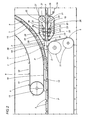
- the second conveyor 7, which occupies a position above the first conveyor 6, comprises a respective transport branch 15 composed of a horizontal upper infeed segment 16 on which the packets 3 emerging from the packer 5 are taken up, also a descending segment denoted 17, and a horizontal lower outfeed segment 18 facing the top transport branch 12 of the first conveyor 6 in the neighbourhood of the transfer point 8.
- the aforementioned descending segment 17 includes a substantially vertical rectilinear portion 17a, and two curvilinear connecting portions 17b and 17c merged respectively with the horizontal upper and lower segments 16 and 18.
- the unit 2 further comprises a third belt conveyor and a fourth belt conveyor, denoted 19 and 20 respectively.
- the third conveyor 19 is looped around a driving pulley 21 and around a plurality of idle rollers 22 and 23, the rollers denoted 22 occupying fixed positions, the rollers denoted 23 mounted flexibly to respective spring elements 24.
- the third conveyor 19 presents an active top branch 25 running in the direction of the arrow F in figure 2, and a bottom return branch 26.
- the fourth conveyor 20 is looped around a driving pulley 27 and around a plurality of idle rollers 28 and 29, the rollers denoted 28 occupying fixed positions and the rollers denoted 29 mounted flexibly to respective spring elements 30.
- the fourth conveyor 20 presents an active bottom branch 31 running in the direction of the arrow F in figure 2, and a top return branch 32.
- the two active branches 25 and 31 presented respectively by the third and fourth conveyors 19 and 20 are mutually opposed.
- the unit 2 further comprises a magazine 33 of multiple hopper type design, in which to store packets 3 releasable to the first conveyor 6 in a manner to be described in due course.
- a fifth belt conveyor 34 substantially of familiar type, not described here in detail, is positioned to coincide with an area 35 at which the packets 3 are released from the magazine 33 and serves to feed the selfsame packets 3 toward the third and fourth conveyors 19 and 20.
- the unit 2 comprises a pair of timing rollers 36 located between the third conveyor 19 and the first conveyor 6, positioned one on each side of the selfsame first conveyor 6; one only of the two rollers 36 is visible in the accompanying drawings.
- the two rollers 36 are rotatable about mutually parallel axes A1, and set in motion by drive means (not indicated) in opposing directions of rotation.
- the unit 2 comprises a guide device 37 of which the purpose is to support and allow packets 3 coming from the second conveyor 7 to slide onto the first conveyor 6, while at the same time allowing packets 3 already on the first conveyor 6 to pass directly through the transfer point 8.
- the guide device 37 includes a plurality of pairs of bridging members 38 angled downwardly along the feed path P followed by the packets 3 along the first conveyor 6.
- the two bridging members 38 of each pair are positioned respectively on opposite sides of the feed path P and present respective portions 38a converging on the selfsame path P.
- the bridging members 38 are flexibly resilient when engaged, in a direction transverse to the rectilinear direction D aforementioned, by the advancing packets 3 carried in the pockets 10 of the first conveyor 6.
- Each bridging member 38 is incorporated into a lever element 39 embodied as a rocker and mounted to a relative fulcrum pivot 40, capable of rocking thus on a respective axis A2 independently of all the other lever elements 39.
- Each lever element 39 comprises a first arm 39a and a second arm 39b positioned on opposite sides of the pivot 40.
- the first arm 39a presents a side face 41 placed to engage the packets 3 occupying the pockets 10 of the first conveyor 6, and a flat face 42 on which the packets 3 directed along the feed path P by the second conveyor 7 are supported and able to slide.
- the aforementioned converging portion 38a is delimited by the side face 41, and thus forms a part of the first arm 39a presented by the lever element 39.
- each lever element 39 Anchored to the second arm 39b of each lever element 39 is a first end 43a of a coil spring 43, of which a second end 43b is anchored to a mounting element 44.
- the lever elements 39 are mounted sequentially in sets of three, each to a respective plate 45 carried in turn by a vertical bulkhead 46 of the frame (not illustrated) on which the conveying unit 2 is carried.
- the second conveyor 7 will be seen to comprise an element 47, extending along the descending segment 17, by means of which to guide and restrain the packets 3 advancing along the conveyor 7.
- the guiding and restraining element 47 is offered to the descending segment 17 in such a manner as to keep each of the packets 3 lodged internally of the relative pocket 10, and terminates at the transfer point 8 in a tongue 48 adjacent to the bridging members 38 of the guidance device 37.
- a proximity transducer 49 Positioned along the transport branch 15 of the second conveyor 7, at a given point upstream of the transfer point 8, is a proximity transducer 49 such as will verify the presence or absence of packets 3 in the respective pockets 10 of the conveyor 7.
- the transducer 49 provides the conveying unit 2 with relative sensing means 50 serving to detect the presence of the packets 3.
- the guide device 37 functions both as means 51 by which packets 3 advancing in the pockets 10 of the second conveyor 7 are slidably supported, and as means 52 by which packets 3 already advancing in the pockets 10 of the first conveyor 6 are afforded a passage through the transfer point 8.
- the timing rollers 36 combine with the third conveyor 19 and the fourth conveyor 20 to provide the conveying unit 2 with placement means 53 by which packets 3 are directed into the pockets 10 of the first conveyor 6.
- the conveying unit 2 will include a computerized master control unit (not illustrated) serving to manage the various operations performed by the unit 2.
- single packets 3 emerging from the packer 5 are directed onto the horizontal upper segment 16 presented by the transport branch 15 of the second conveyor 6, each one being placed, by substantially familiar methods, in a respective pocket 10 delimited by the aforementioned ridges 9.
- the packets 3 advance along the feed path P and down the descending segment 17 of the transport branch 15, supported by the guiding and restraining element 47, arriving ultimately at the point 8 of transfer to the first conveyor 6.
- the single packets 3 slide over the flat faces 42 of the lever elements 39 and locate in a respective pocket 10 presented by the top transport branch 12 of the first conveyor 6.
- a pocket 10 of the second conveyor 7 may happen to contain no packet 3, in which case the empty space is detected by the aforementioned transducer 49 located along the feed path P, upstream of the transfer point 8, and a relative signal is sent to the computerized master control unit (not illustrated).
- the computerized master control unit will pilot the placement means 53 to respond by preparing a recycled packet, denoted 3', in readiness to fill the pocket 10 of the first conveyor 6 that should have been occupied, had the missing packet 3 been transferred as normal from the second conveyor 7 to the first conveyor 6.
- the forwardmost of the packets 3' advanced by the third and fourth conveyors 19 and 20 is positioned in contact with the cylindrical surfaces of the timing rollers 36.
- the timing rollers 36 are set in contrarotation at high speed about their respective axes A1, so that when contact is made with a recycled packet 3' fed forward by the third and fourth conveyors 19 and 20, the packet 3' is accelerated to the point of locating against one ridge 9 of a predetermined pocket 10 presented by the first conveyor 6.
- the pocket 10 in question is precisely the one that would have been occupied by the packet 3 missing from the second conveyor 7.
- the aforementioned packet 3' is directed forward by a ridge 9 (not illustrated) of the corresponding pocket 10 and advanced along the feed direction D, to the point of engaging the lever elements 39 of the guide device 37.
- the lever elements 39 are caused to pivot on their respective fulcrum axes A2, spreading substantially in a transverse direction to allow the passage of the packet 3' and then closing again immediately, returned by the action of the springs 43.
- the unit 2 is equipped with a plurality of the aforementioned lever elements 39, so that the section of the feed path P covered by the guide device 37 can be split between the selfsame levers, or rather between the relative flat faces 42; in other words, observing figure 7, whilst the lever elements 39 farthest downstream along the feed path P remain spread to allow the passage of a recycled packet 3', the elements 39 farthest upstream will already have been returned to the closed position by the action of the springs 43, in readiness to support another packet 3 advancing on the second conveyor 7. Self-evidently, in the event that two or more adjacent packets 3 may be missing on the second conveyor 7, the unit 2 is able to fill the gap by admitting two or more recycled packets 3' in succession.
- a first continuously driven conveyor 6 equipped with pockets 10 can be supplied with packets 3, through the agency of placement means 53, from a second continuously driven conveyor 7 also equipped with pockets 10, in such a way as to compensate any gaps presented by the second of the two conveyors.
- packets 3 leaving the packer 5 could be fed by the conveying unit 2 directly to the first conveyor 6, with the aforementioned transducer 49 providing sensing means 50 located alongside the first conveyor 6 and the placement means 53 operating in conjunction with the second conveyor 7 so as to direct the recycled packets 3' onto this same second conveyor 7.
- coil type return springs 43 of the lever elements 39 might be replaced by other elements equivalent in terms of the art, such as pneumatic or electric actuators (not illustrated).
- first and second conveyors 6 and 7 described and illustrated could be driven intermittently.
Abstract
Description
- The present invention relates to a unit for conveying products.
- In particular, the present invention relates to a unit for conveying products to a user machine, and more exactly a unit comprising a first and a second conveyor set in continuous motion.
- The invention finds application, to advantage, in the art field of conveying systems for packets of cigarettes, to which reference is made explicitly in the specification albeit implying no limitation in scope.
- In a typical cigarette packaging line, packets turned out by a cigarette packer are directed into a cellophaner, which proceeds to envelop each one in an overwrapping of polypropylene; the packets are supplied to the cellophaner by a first conveyor carrying the main flow from the packer, randomly spaced, and by a second recycle conveyor or hopper, which carries unblemished packets readmitted to the production cycle upstream of the cellophaner.
- The readmission step is made necessary for one reason more than any other, namely that to operate correctly, the user machine must be supplied with packets in a continuous and ordered succession, whereas in practice it can happen that gaps will appear in the flow of packets proceeding toward the cellophaner, and in consequence empty spaces on the conveyor, attributable to various different causes.
- Owing to constraints determining the way that the outfeed conveyor of the cigarette packer and the infeed conveyor of the cellophaner are positioned in space, the path followed by the aforementioned first or main conveyor will generally incorporate 90° and 180° bends and changes of level, and it is therefore normal for the conveying path to include curvilinear stretches along which the packets are directed downwards toward the cellophaner. These non-rectilinear stretches of the conveying path can cause damage to packets propelled forward at the high operating speeds of modern cigarette packers. In effect, the packets advance broadside along the rectilinear sections of the path, proceeding in close order with one larger side face resting on the belt of the conveyor, and are caused to strike one against another when passing through the bends and down the gradients of the path. In particular, it will often happen that the corner of one packet rubs against the flank face of the packet in front, generating wear.
- A further problem connected with random spacing of the packets is that the dynamic by which they are carried along the path cannot be controlled, so that it is not possible to apply additional items to the packets, such as coupons and/or leaflets, before their entry into the cellophaner.
- Positioned generally alongside the main conveyor, the recycle hopper containing readmissible packets is associated with a push rod designed to eject the lowest packet from the hopper and direct it onto the main conveyor whenever there is a gap in the flow of packets advancing on the selfsame conveyor.
- More particularly, given that the packets do not advance in a regularly spaced succession, it is not possible with this type of feed system to predict when there are going to be gaps on the conveyor, and the recycle hopper comes into operation only when the cigarette packer is at standstill. Even with the recycle hopper installed and in operation, consequently, there will always be unpredictable gaps in the flow of packets directed along the main conveyor toward the cellophaner, and the resulting empty spaces reduce the efficiency of the machine considerably.
- Attempts have been made to avoid damage to the packets along the non-rectilinear stretches of the main conveyor, by employing conveyors on which the selfsame packets are fed to the cellophaner in a regularly spaced succession, each one occupying a stable position determined by a relative projection or ridge on the surface on the conveyor.
- A solution of this type precludes the use of the conventional recycle hopper to readmit unblemished packets as described above, since, at the high operating speeds of the user machine, the cycle time needed for a push rod to transfer a packet from the hopper to the main conveyor would be much longer than the time taken by the empty space to pass across the outlet of the selfsame hopper.
- Solutions of other types would be notably complex from the constructional standpoint, inasmuch as they would be based on the use of a hopper capable of traversing parallel with the feed direction of the flow of packets and thus allowing the outlet to track the adjacent gap so that a recycled packet can be placed accurately in the required position.
- The object of the present invention is to provide a conveying unit for products, presenting a first conveyor and a second conveyor feeding respective ordered flows of the products, such as will allow products missing from the first ordered flow to be made up with products from the second ordered flow, even at the high operating speeds of user machines, employing a device of simple and practical design.
- Adopting a unit in accordance with the invention, in particular, any packets missing from the first ordered flow can be made up as the selfsame flow advances, without its progress being interrupted.
- The stated object is realized, according to the present invention, in a conveying unit of which the characterizing features are as recited in
claim 1 appended or in any of the claims dependent directly or indirectly onclaim 1. - The invention will now be described in detail, by way of example, with the aid of the accompanying drawings, in which:
- figure 1 shows a preferred embodiment of the unit for conveying products according to the present invention, viewed schematically in a side elevation with certain parts omitted in the interests of clarity;
- figure 2 shows a detail of the unit in figure 1, viewed schematically in a side elevation and in a different operating situation;
- figure 3 shows a detail of the unit in figure 1, viewed in perspective from above and with certain parts omitted better to illustrate others;
- figures 4 and 5 are respective schematic views showing a detail of the unit in figures 1 and 2, in two different operating situations;
- figures 6 and 7 show a detail of the conveying unit according to the present invention, viewed in plan from above with certain parts omitted, and in two different operating situations.
- Referring to figure 1,
numeral 1 shows a portion of a cigarette packing line, in its entirety. - The
line 1 in question comprises a unit 2 by whichpackets 3 of cigarettes are conveyed to a user machine such as a cellophaner, represented schematically in figure 1 by a block denoted 4. - The
packets 3 are turned out by an upstream unit consisting for example in a cigarette packer, shown schematically in figure 1 as a block denoted 5, and directed along the conveying unit 2 following a feed path denoted P. - The conveying unit 2 includes a
first conveyor 6, set in continuous motion, from whichpackets 3 are directed into theaforementioned user machine 4, and asecond conveyor 7, likewise set in continuous motion, from whichpackets 3 are directed onto thefirst conveyor 6. In an alternative embodiment of the unit 2, theconveyors - The advancing
packets 3 pass from thesecond conveyor 7 onto thefirst conveyor 6 at a transfer point denoted 8. - The
first conveyor 6 consists in a belt conveyor of familiar type equipped withridges 9 combining in pairs to createrespective pockets 10, each one of which accommodates asingle packet 3. - The
first conveyor 6 is looped around a plurality ofpulleys 11 of which at least one (not indicated) is a driving pulley, whilst the remainder are idle pulleys. - Only certain of the
pulleys 11 are illustrated in the accompanying drawings. - The
first conveyor 6 comprises a substantially horizontaltop transport branch 12 extending along a rectilinear direction D and providing one segment of the feed path P along which thepackets 3 are directed toward the cellophaner. - Like the
first conveyor 6, thesecond conveyor 7 consists in a beltconveyor presenting ridges 9 that combine in pairs to establish a succession ofpockets 10 each accommodating asingle packet 3. - The
second conveyor 7 is looped around a plurality ofpulleys 13 androllers 14. - Not all of the pulleys denoted 13 are illustrated in the accompanying drawings, and at least one (not indicated) is power driven whilst the remainder are idle pulleys.
- The
second conveyor 7, which occupies a position above thefirst conveyor 6, comprises arespective transport branch 15 composed of a horizontal upper infeedsegment 16 on which thepackets 3 emerging from thepacker 5 are taken up, also a descending segment denoted 17, and a horizontal loweroutfeed segment 18 facing thetop transport branch 12 of thefirst conveyor 6 in the neighbourhood of thetransfer point 8. - The aforementioned descending
segment 17 includes a substantially verticalrectilinear portion 17a, and two curvilinear connectingportions lower segments - Referring to figures 1 and 2, the unit 2 further comprises a third belt conveyor and a fourth belt conveyor, denoted 19 and 20 respectively.
- As illustrated in figure 2, the
third conveyor 19 is looped around adriving pulley 21 and around a plurality ofidle rollers respective spring elements 24. - The
third conveyor 19 presents anactive top branch 25 running in the direction of the arrow F in figure 2, and abottom return branch 26. - Similarly to the
third conveyor 19, thefourth conveyor 20 is looped around adriving pulley 27 and around a plurality ofidle rollers 28 and 29, the rollers denoted 28 occupying fixed positions and the rollers denoted 29 mounted flexibly torespective spring elements 30. - The
fourth conveyor 20 presents anactive bottom branch 31 running in the direction of the arrow F in figure 2, and atop return branch 32. - The two
active branches fourth conveyors - With reference to figure 1, the unit 2 further comprises a
magazine 33 of multiple hopper type design, in which to storepackets 3 releasable to thefirst conveyor 6 in a manner to be described in due course. Afifth belt conveyor 34 substantially of familiar type, not described here in detail, is positioned to coincide with anarea 35 at which thepackets 3 are released from themagazine 33 and serves to feed theselfsame packets 3 toward the third andfourth conveyors - Referring to figure 2, the unit 2 comprises a pair of
timing rollers 36 located between thethird conveyor 19 and thefirst conveyor 6, positioned one on each side of the selfsamefirst conveyor 6; one only of the tworollers 36 is visible in the accompanying drawings. - The two
rollers 36 are rotatable about mutually parallel axes A1, and set in motion by drive means (not indicated) in opposing directions of rotation. - As discernible from the detailed illustration of figure 3, the unit 2 comprises a
guide device 37 of which the purpose is to support and allowpackets 3 coming from thesecond conveyor 7 to slide onto thefirst conveyor 6, while at the sametime allowing packets 3 already on thefirst conveyor 6 to pass directly through thetransfer point 8. - The
guide device 37 includes a plurality of pairs ofbridging members 38 angled downwardly along the feed path P followed by thepackets 3 along thefirst conveyor 6. - As illustrated to advantage in figures 6 and 7, moreover, the two
bridging members 38 of each pair are positioned respectively on opposite sides of the feed path P and presentrespective portions 38a converging on the selfsame path P. - In addition, the
bridging members 38 are flexibly resilient when engaged, in a direction transverse to the rectilinear direction D aforementioned, by the advancingpackets 3 carried in thepockets 10 of thefirst conveyor 6. - Each
bridging member 38 is incorporated into alever element 39 embodied as a rocker and mounted to arelative fulcrum pivot 40, capable of rocking thus on a respective axis A2 independently of all theother lever elements 39. - Each
lever element 39 comprises afirst arm 39a and asecond arm 39b positioned on opposite sides of thepivot 40. - The
first arm 39a presents aside face 41 placed to engage thepackets 3 occupying thepockets 10 of thefirst conveyor 6, and aflat face 42 on which thepackets 3 directed along the feed path P by thesecond conveyor 7 are supported and able to slide. - The
aforementioned converging portion 38a is delimited by theside face 41, and thus forms a part of thefirst arm 39a presented by thelever element 39. - Anchored to the
second arm 39b of eachlever element 39 is afirst end 43a of acoil spring 43, of which asecond end 43b is anchored to amounting element 44. - As illustrated in figure 3, the
lever elements 39 are mounted sequentially in sets of three, each to arespective plate 45 carried in turn by avertical bulkhead 46 of the frame (not illustrated) on which the conveying unit 2 is carried. - Observing figures 2 and 3, the
second conveyor 7 will be seen to comprise anelement 47, extending along thedescending segment 17, by means of which to guide and restrain thepackets 3 advancing along theconveyor 7. - The guiding and restraining
element 47 is offered to the descendingsegment 17 in such a manner as to keep each of thepackets 3 lodged internally of therelative pocket 10, and terminates at thetransfer point 8 in atongue 48 adjacent to thebridging members 38 of theguidance device 37. - Positioned along the
transport branch 15 of thesecond conveyor 7, at a given point upstream of thetransfer point 8, is aproximity transducer 49 such as will verify the presence or absence ofpackets 3 in therespective pockets 10 of theconveyor 7. - The
transducer 49 provides the conveying unit 2 with relative sensing means 50 serving to detect the presence of thepackets 3. - The
guide device 37 functions both asmeans 51 by whichpackets 3 advancing in thepockets 10 of thesecond conveyor 7 are slidably supported, and asmeans 52 by whichpackets 3 already advancing in thepockets 10 of thefirst conveyor 6 are afforded a passage through thetransfer point 8. - The timing
rollers 36 combine with thethird conveyor 19 and thefourth conveyor 20 to provide the conveying unit 2 with placement means 53 by whichpackets 3 are directed into thepockets 10 of thefirst conveyor 6. - In addition, the conveying unit 2 will include a computerized master control unit (not illustrated) serving to manage the various operations performed by the unit 2.
- In operation,
single packets 3 emerging from thepacker 5 are directed onto the horizontalupper segment 16 presented by thetransport branch 15 of thesecond conveyor 6, each one being placed, by substantially familiar methods, in arespective pocket 10 delimited by theaforementioned ridges 9. - Thus, the
packets 3 advance along the feed path P and down the descendingsegment 17 of thetransport branch 15, supported by the guiding and restrainingelement 47, arriving ultimately at thepoint 8 of transfer to thefirst conveyor 6. - Passing from the
second conveyor 7 to thefirst conveyor 6, thesingle packets 3 slide over the flat faces 42 of thelever elements 39 and locate in arespective pocket 10 presented by thetop transport branch 12 of thefirst conveyor 6. - For a number of different reasons such as, for example, the rejection of
defective packets 3 emerging from thecigarette packer 5, apocket 10 of thesecond conveyor 7 may happen to contain nopacket 3, in which case the empty space is detected by theaforementioned transducer 49 located along the feed path P, upstream of thetransfer point 8, and a relative signal is sent to the computerized master control unit (not illustrated). - The computerized master control unit will pilot the placement means 53 to respond by preparing a recycled packet, denoted 3', in readiness to fill the
pocket 10 of thefirst conveyor 6 that should have been occupied, had themissing packet 3 been transferred as normal from thesecond conveyor 7 to thefirst conveyor 6. - For this to occur, more exactly, the forwardmost of the packets 3' advanced by the third and
fourth conveyors rollers 36. - The timing
rollers 36 are set in contrarotation at high speed about their respective axes A1, so that when contact is made with a recycled packet 3' fed forward by the third andfourth conveyors ridge 9 of apredetermined pocket 10 presented by thefirst conveyor 6. - The
pocket 10 in question is precisely the one that would have been occupied by thepacket 3 missing from thesecond conveyor 7. - As illustrated in figure 6, the aforementioned packet 3' is directed forward by a ridge 9 (not illustrated) of the
corresponding pocket 10 and advanced along the feed direction D, to the point of engaging thelever elements 39 of theguide device 37. - Referring to figures 6 and 7, as the recycled packet 3' makes contact with the side faces 41 of the
single lever elements 39, thelever elements 39 are caused to pivot on their respective fulcrum axes A2, spreading substantially in a transverse direction to allow the passage of the packet 3' and then closing again immediately, returned by the action of thesprings 43. - As illustrated in figures 3, 6 and 7, the unit 2 is equipped with a plurality of the
aforementioned lever elements 39, so that the section of the feed path P covered by theguide device 37 can be split between the selfsame levers, or rather between the relative flat faces 42; in other words, observing figure 7, whilst thelever elements 39 farthest downstream along the feed path P remain spread to allow the passage of a recycled packet 3', theelements 39 farthest upstream will already have been returned to the closed position by the action of thesprings 43, in readiness to support anotherpacket 3 advancing on thesecond conveyor 7. Self-evidently, in the event that two or moreadjacent packets 3 may be missing on thesecond conveyor 7, the unit 2 is able to fill the gap by admitting two or more recycled packets 3' in succession. - Thus, by replenishing any
vacant pockets 10 of thefirst conveyor 6 with recycled packets 3' fed directly onto thetransport branch 12 of this samefirst conveyor 6, it becomes possible to maintain an unbroken succession ofpackets 3 downstream of thetransfer point 8, each occupying arespective pocket 10 of theconveyor 6. - With a conveying unit 2 according to the present invention, advantageously, a first continuously driven
conveyor 6 equipped withpockets 10 can be supplied withpackets 3, through the agency of placement means 53, from a second continuously drivenconveyor 7 also equipped withpockets 10, in such a way as to compensate any gaps presented by the second of the two conveyors. - In an alternative embodiment of the invention, not illustrated,
packets 3 leaving thepacker 5 could be fed by the conveying unit 2 directly to thefirst conveyor 6, with theaforementioned transducer 49 providing sensing means 50 located alongside thefirst conveyor 6 and the placement means 53 operating in conjunction with thesecond conveyor 7 so as to direct the recycled packets 3' onto this samesecond conveyor 7. - In other alternative embodiments of the present invention, likewise not illustrated, the coil type return springs 43 of the
lever elements 39 might be replaced by other elements equivalent in terms of the art, such as pneumatic or electric actuators (not illustrated). - In another alternative embodiment of a conveying unit 2 according to the present invention, again not illustrated, the first and
second conveyors
Claims (16)
- A unit for conveying products to a user machine, comprising:- a first conveyor (6) with pockets (10) feeding a succession of products (3) toward the user machine (4) ;- a second conveyor (7) with pockets (10) feeding products (3) onto the first conveyor (6) at a transfer point (8);- sensing means (50) serving to detect the presence of products (3) in the pockets (10) of the second conveyor (7);- placement means (53), interlocked to the sensing means (50), by which products (3) can be directed into the pockets (10) of the first conveyor (6) so as to obtain an unbroken succession of products (3) occupying the pockets (10) of the first conveyor (6) downstream of the transfer point (8).
- A conveying unit as in claim 1, wherein the first conveyor (6) consists in an endless conveying loop presenting a substantially horizontal top transport branch (12) extending along a feed direction (D) and establishing one section of a feed path (P) followed by the products (3), whilst the second conveyor (7) consists in an endless conveying loop located above the first conveyor (6) and comprises a transport branch (15) including a descending segment (17), and a substantially horizontal segment (18) positioned facing the top transport branch (12) of the first conveyor (6) at least near the transfer point (8).
- A conveying unit as in claim 1 or 2, comprising guide means (37), located at the transfer point (8), by which products (3) are directed from the pockets (10) of the second conveyor (7) into the pockets (10) of the first conveyor (6).
- A conveying unit as in claim 3, wherein the guide means (37) function both as means (51) slidably supporting the packets (3) occupying the pockets (10) of the second conveyor (7), and as means (52) affording a passage to the products (3) occupying the pockets (10) of the first conveyor (6).
- A conveying unit as in claim 4, wherein the guide means (37) comprise at least two bridging members (38) angled downwardly along the feed path (P) followed by the products (3) on the first conveyor (6), located on opposite sides of the selfsame feed path (P), and comprising respective portions (38a) converging on the feed path (P) that are flexibly resilient, in a direction transverse to the feed direction (D), when engaged by the advancing products (3) occupying the pockets (10) of the first conveyor (6).
- A conveying unit as in claim 5, wherein the guide means (37) comprise a plurality of bridging members (38).
- A conveying unit as in claim 5 or 6, wherein each bridging member (38) is incorporated into a lever element (39) able to rock on a respective fulcrum axis (A2) independently of each of the other lever elements (39), presenting a side face (41) placed to engage successive products (3) occupying the pockets (10) of the first conveyor (6), and a flat face (42) on which products (3) advanced by the second conveyor (7) are slidably supported.
- A conveying unit as in claim 7, wherein each of the lever elements (39) is embodied as a rocker and comprises a first arm (39a) incorporating the side and flat faces (41, 42), and a second arm (39b) with which spring means (43) are associated in such a way as to oppose the rocking motion of the lever element (39).
- A conveying unit as in claim 7 or 8, of which the guide means (37) comprise a plurality of lever elements (39) located on each of the opposite sides of the feed path (P) followed by the products (3), wherein the lever elements (39) on each side are ordered in series, in such a way as will allow two different lever elements (39) on the same side to engage simultaneously with a product (3) advancing on the first conveyor (6) and with a product (3) advancing on the second conveyor (7), respectively.
- A conveying unit as in claims 1 to 9, wherein the placement means (53) comprise a pair of timing rollers (36) by which products (3) are accelerated to the end of positioning each one in a respective pocket (10) of the first conveyor (6).
- A conveying unit as in claim 10, wherein the placement means (53) comprise a third conveyor (19) by which the products (3) are directed toward the timing rollers (36).
- A conveying unit as in claims 1 to 11, wherein the pockets (10) of the first and second conveyors (6, 7) are delimited by ridges (9) ordered along the developable length of each conveyor (6, 7) at a predetermined distance one from the next.
- A unit for conveying products to a user machine, comprising:a first conveyor (6) with pockets (10) feeding a succession of products (3) toward the user machine (4);a second conveyor (7) with pockets (10) feeding products (3) onto the first conveyor (6) at a transfer point (8);sensing means (50) serving to detect the presence of products (3) in the pockets (10) of the first conveyor (6);placement means (53), interlocked to the sensing means (50), by which products (3) can be directed into the pockets (10) of the second conveyor (7) so as to obtain an unbroken succession of products (3) occupying the pockets (10) of the first conveyor (6) downstream of the transfer point (8).
- A conveying unit as in claim 13, comprising guide means (37), located at the transfer point (8), by which products (3) are directed from the pockets (10) of the second conveyor (7) into the pockets (10) of the first conveyor (6).
- A conveying unit as in claims 1 to 14, wherein both the first conveyor (6) and the second conveyor (7) are driven continuously.
- A conveying unit as in claims 1 to 14, wherein both the first conveyor (6) and the second conveyor (7) are driven intermittently.
Applications Claiming Priority (1)
| Application Number | Priority Date | Filing Date | Title |
|---|---|---|---|
| IT000494A ITBO20040494A1 (en) | 2004-08-03 | 2004-08-03 | PRODUCT CONVEYANCE UNIT |
Publications (2)
| Publication Number | Publication Date |
|---|---|
| EP1623940A1 true EP1623940A1 (en) | 2006-02-08 |
| EP1623940B1 EP1623940B1 (en) | 2008-06-18 |
Family
ID=35149439
Family Applications (1)
| Application Number | Title | Priority Date | Filing Date |
|---|---|---|---|
| EP05425535A Not-in-force EP1623940B1 (en) | 2004-08-03 | 2005-07-22 | A unit for conveying products |
Country Status (7)
| Country | Link |
|---|---|
| US (1) | US7644815B2 (en) |
| EP (1) | EP1623940B1 (en) |
| JP (1) | JP2006044801A (en) |
| CN (1) | CN1736828B (en) |
| AT (1) | ATE398593T1 (en) |
| DE (1) | DE602005007542D1 (en) |
| IT (1) | ITBO20040494A1 (en) |
Cited By (1)
| Publication number | Priority date | Publication date | Assignee | Title |
|---|---|---|---|---|
| GB2454732A (en) * | 2007-11-17 | 2009-05-20 | Vincent Small | Packet inserter for packet wrapping system |
Families Citing this family (9)
| Publication number | Priority date | Publication date | Assignee | Title |
|---|---|---|---|---|
| US7938252B2 (en) * | 2007-12-21 | 2011-05-10 | Cinetic Sorting Corp. | Unstacking conveyor with floating surface |
| US8931240B2 (en) | 2008-10-27 | 2015-01-13 | Formax, Inc. | Shuttle system and method for moving food products into packaging |
| CN102853212B (en) * | 2012-09-20 | 2015-08-26 | 赵炳泉 | The continuous packing producing line of separate compartment type vacuum insulation panel and production method |
| CN103204273B (en) * | 2013-02-05 | 2016-08-03 | 天津市天驰机电技术发展有限公司 | Packet transparent paper packer tobacco bale secondary package fills into device |
| DE102015002798A1 (en) * | 2015-03-06 | 2016-09-08 | Focke & Co. (Gmbh & Co. Kg) | Device for transporting objects, in particular packages |
| CN105540138B (en) * | 2016-01-11 | 2017-10-27 | 昆明理工大学 | A kind of tobacco leaf motion state measurement apparatus |
| BR112018016772A2 (en) * | 2016-02-19 | 2018-12-26 | Gebo Cermex Canada Inc | product detector |
| IT201700099359A1 (en) | 2017-09-05 | 2019-03-05 | Gd Spa | System and method for weighing containers |
| CN109941503A (en) * | 2019-04-24 | 2019-06-28 | 漳州松田包装机械有限公司 | A kind of high-speed pillow type packaging machine Y type binary channels tailstock |
Citations (6)
| Publication number | Priority date | Publication date | Assignee | Title |
|---|---|---|---|---|
| US4558779A (en) * | 1982-10-13 | 1985-12-17 | Rovema Verpackungsmaschinen Gmbh | Conveyor apparatus, in particular for use in packaging plants |
| US5186310A (en) * | 1992-02-05 | 1993-02-16 | Winchester Donald M | Vertical lift conveyor |
| EP0613838A1 (en) * | 1993-03-04 | 1994-09-07 | Geca S.R.L. | Apparatus for conveying and grouping products |
| EP0709315A1 (en) * | 1994-10-27 | 1996-05-01 | HITECH SYSTEMS S.r.l. | Improved machine for grouping individually-conveyed products, particularly food products, confectionery products and the like, for packaging |
| DE29521082U1 (en) * | 1995-06-19 | 1996-08-01 | Schubert Gerhard Gmbh | Grouping and buffering device |
| DE29817239U1 (en) * | 1997-11-07 | 1998-11-26 | Paal Kg Hans | Intermediate storage device |
Family Cites Families (9)
| Publication number | Priority date | Publication date | Assignee | Title |
|---|---|---|---|---|
| US2603395A (en) * | 1948-07-27 | 1952-07-15 | Molins Machine Co Ltd | Collecting mechanism for cigarettes and other rod-shaped articles |
| GB8924078D0 (en) * | 1989-10-26 | 1989-12-13 | Tetra Pak Ab | Continuous to intermittent feeding interface |
| JPH05330636A (en) * | 1992-05-25 | 1993-12-14 | Mitsubishi Materials Corp | Long-size body feeding device |
| IT1260231B (en) * | 1992-12-18 | 1996-04-02 | Gd Spa | DEVICE TO FEED SMOKING ITEMS, IN PARTICULAR CIGARETTES, TO A GROUPING MACHINE |
| IT1260227B (en) * | 1992-12-18 | 1996-04-02 | Gd Spa | CIGARETTE PACKAGE FEEDING DEVICE TO A STICKING MACHINE |
| US5971133A (en) * | 1997-05-08 | 1999-10-26 | Hk Systems, Inc. | Conveyor assembly incorporating a pop-up swivel wheel diverter |
| JP3240466B2 (en) * | 1997-10-31 | 2001-12-17 | 株式会社フジキカイ | Article supply equipment for processing machines such as packaging machines |
| IT1299948B1 (en) * | 1998-04-02 | 2000-04-04 | Azionaria Costruzioni Acma Spa | METHOD AND DEVICE FOR THE FORMATION OF GROUPS OF FLAT ARTICLES. |
| DE50204381D1 (en) * | 2001-10-15 | 2006-02-09 | Ferag Ag | Method and device for the sequential feeding of objects into processing |
-
2004
- 2004-08-03 IT IT000494A patent/ITBO20040494A1/en unknown
-
2005
- 2005-07-22 AT AT05425535T patent/ATE398593T1/en not_active IP Right Cessation
- 2005-07-22 DE DE602005007542T patent/DE602005007542D1/en active Active
- 2005-07-22 EP EP05425535A patent/EP1623940B1/en not_active Not-in-force
- 2005-07-27 US US11/189,772 patent/US7644815B2/en not_active Expired - Fee Related
- 2005-08-01 CN CN2005100911015A patent/CN1736828B/en not_active Expired - Fee Related
- 2005-08-02 JP JP2005224237A patent/JP2006044801A/en active Pending
Patent Citations (6)
| Publication number | Priority date | Publication date | Assignee | Title |
|---|---|---|---|---|
| US4558779A (en) * | 1982-10-13 | 1985-12-17 | Rovema Verpackungsmaschinen Gmbh | Conveyor apparatus, in particular for use in packaging plants |
| US5186310A (en) * | 1992-02-05 | 1993-02-16 | Winchester Donald M | Vertical lift conveyor |
| EP0613838A1 (en) * | 1993-03-04 | 1994-09-07 | Geca S.R.L. | Apparatus for conveying and grouping products |
| EP0709315A1 (en) * | 1994-10-27 | 1996-05-01 | HITECH SYSTEMS S.r.l. | Improved machine for grouping individually-conveyed products, particularly food products, confectionery products and the like, for packaging |
| DE29521082U1 (en) * | 1995-06-19 | 1996-08-01 | Schubert Gerhard Gmbh | Grouping and buffering device |
| DE29817239U1 (en) * | 1997-11-07 | 1998-11-26 | Paal Kg Hans | Intermediate storage device |
Cited By (1)
| Publication number | Priority date | Publication date | Assignee | Title |
|---|---|---|---|---|
| GB2454732A (en) * | 2007-11-17 | 2009-05-20 | Vincent Small | Packet inserter for packet wrapping system |
Also Published As
| Publication number | Publication date |
|---|---|
| US20060070354A1 (en) | 2006-04-06 |
| US7644815B2 (en) | 2010-01-12 |
| CN1736828A (en) | 2006-02-22 |
| CN1736828B (en) | 2010-04-21 |
| DE602005007542D1 (en) | 2008-07-31 |
| ITBO20040494A1 (en) | 2004-11-03 |
| EP1623940B1 (en) | 2008-06-18 |
| ATE398593T1 (en) | 2008-07-15 |
| JP2006044801A (en) | 2006-02-16 |
Similar Documents
| Publication | Publication Date | Title |
|---|---|---|
| EP1623940B1 (en) | A unit for conveying products | |
| US7497316B2 (en) | Sortation conveyor apparatus and methods | |
| US4756400A (en) | Product supply system for accumulation packaging machine | |
| EP0480436A2 (en) | Distributing and collecting device for products to be conveyed | |
| EP0624143A1 (en) | Method and device for arranging a stream of products. | |
| US6508350B1 (en) | Apparatus for avoiding falling over of objects conveyed on a conveyor system | |
| JP2004502608A (en) | Apparatus for discharging cigarette parcels from packaging machines | |
| US20080093791A1 (en) | Unit and a method for feeding labels in a packer machine for tobacco products | |
| US9908646B2 (en) | Method and apparatus for placing products into containers in a robot line | |
| RU2595220C2 (en) | Transport and packaging device for eggs | |
| AU688747B2 (en) | Method and apparatus for feeding, grouping and orientating articles | |
| US7174694B2 (en) | Loading objects into individual pockets of a moving web | |
| US5211529A (en) | Horizontal staging hopper | |
| JP2008529932A (en) | Apparatus and method for conveying rod-shaped articles | |
| US5309697A (en) | Chewing gum packaging machine | |
| US6830145B2 (en) | System for use in an assembly line | |
| US3799324A (en) | Automatic cigarette feed machine | |
| SK279527B6 (en) | A process and device for conveying articles | |
| US4262792A (en) | Distributing streams of articles | |
| US3976085A (en) | Automatic cigarette feed machine | |
| US6543600B2 (en) | Early detection photo controls | |
| US4129205A (en) | Method and assembly for feeding articles | |
| KR100556009B1 (en) | Dispensing supply apparatus and method | |
| CN207550677U (en) | A kind of counting transmission device | |
| JP4887401B2 (en) | Multi-row distributor |
Legal Events
| Date | Code | Title | Description |
|---|---|---|---|
| PUAI | Public reference made under article 153(3) epc to a published international application that has entered the european phase |
Free format text: ORIGINAL CODE: 0009012 |
|
| AK | Designated contracting states |
Kind code of ref document: A1 Designated state(s): AT BE BG CH CY CZ DE DK EE ES FI FR GB GR HU IE IS IT LI LT LU LV MC NL PL PT RO SE SI SK TR |
|
| AX | Request for extension of the european patent |
Extension state: AL BA HR MK YU |
|
| 17P | Request for examination filed |
Effective date: 20060302 |
|
| AKX | Designation fees paid |
Designated state(s): AT BE BG CH CY CZ DE DK EE ES FI FR GB GR HU IE IS IT LI LT LU LV MC NL PL PT RO SE SI SK TR |
|
| GRAP | Despatch of communication of intention to grant a patent |
Free format text: ORIGINAL CODE: EPIDOSNIGR1 |
|
| GRAS | Grant fee paid |
Free format text: ORIGINAL CODE: EPIDOSNIGR3 |
|
| GRAA | (expected) grant |
Free format text: ORIGINAL CODE: 0009210 |
|
| AK | Designated contracting states |
Kind code of ref document: B1 Designated state(s): AT BE BG CH CY CZ DE DK EE ES FI FR GB GR HU IE IS IT LI LT LU LV MC NL PL PT RO SE SI SK TR |
|
| REG | Reference to a national code |
Ref country code: GB Ref legal event code: FG4D |
|
| REF | Corresponds to: |
Ref document number: 602005007542 Country of ref document: DE Date of ref document: 20080731 Kind code of ref document: P |
|
| REG | Reference to a national code |
Ref country code: CH Ref legal event code: NV Representative=s name: BUGNION S.A. Ref country code: CH Ref legal event code: EP |
|
| REG | Reference to a national code |
Ref country code: IE Ref legal event code: FG4D |
|
| PG25 | Lapsed in a contracting state [announced via postgrant information from national office to epo] |
Ref country code: SI Free format text: LAPSE BECAUSE OF FAILURE TO SUBMIT A TRANSLATION OF THE DESCRIPTION OR TO PAY THE FEE WITHIN THE PRESCRIBED TIME-LIMIT Effective date: 20080618 Ref country code: FI Free format text: LAPSE BECAUSE OF FAILURE TO SUBMIT A TRANSLATION OF THE DESCRIPTION OR TO PAY THE FEE WITHIN THE PRESCRIBED TIME-LIMIT Effective date: 20080618 |
|
| PG25 | Lapsed in a contracting state [announced via postgrant information from national office to epo] |
Ref country code: NL Free format text: LAPSE BECAUSE OF FAILURE TO SUBMIT A TRANSLATION OF THE DESCRIPTION OR TO PAY THE FEE WITHIN THE PRESCRIBED TIME-LIMIT Effective date: 20080618 Ref country code: AT Free format text: LAPSE BECAUSE OF FAILURE TO SUBMIT A TRANSLATION OF THE DESCRIPTION OR TO PAY THE FEE WITHIN THE PRESCRIBED TIME-LIMIT Effective date: 20080618 Ref country code: PL Free format text: LAPSE BECAUSE OF FAILURE TO SUBMIT A TRANSLATION OF THE DESCRIPTION OR TO PAY THE FEE WITHIN THE PRESCRIBED TIME-LIMIT Effective date: 20080618 Ref country code: LV Free format text: LAPSE BECAUSE OF FAILURE TO SUBMIT A TRANSLATION OF THE DESCRIPTION OR TO PAY THE FEE WITHIN THE PRESCRIBED TIME-LIMIT Effective date: 20080618 |
|
| NLV1 | Nl: lapsed or annulled due to failure to fulfill the requirements of art. 29p and 29m of the patents act | ||
| PG25 | Lapsed in a contracting state [announced via postgrant information from national office to epo] |
Ref country code: CZ Free format text: LAPSE BECAUSE OF FAILURE TO SUBMIT A TRANSLATION OF THE DESCRIPTION OR TO PAY THE FEE WITHIN THE PRESCRIBED TIME-LIMIT Effective date: 20080618 Ref country code: SE Free format text: LAPSE BECAUSE OF FAILURE TO SUBMIT A TRANSLATION OF THE DESCRIPTION OR TO PAY THE FEE WITHIN THE PRESCRIBED TIME-LIMIT Effective date: 20080918 Ref country code: LT Free format text: LAPSE BECAUSE OF FAILURE TO SUBMIT A TRANSLATION OF THE DESCRIPTION OR TO PAY THE FEE WITHIN THE PRESCRIBED TIME-LIMIT Effective date: 20080618 Ref country code: IS Free format text: LAPSE BECAUSE OF FAILURE TO SUBMIT A TRANSLATION OF THE DESCRIPTION OR TO PAY THE FEE WITHIN THE PRESCRIBED TIME-LIMIT Effective date: 20081018 |
|
| PG25 | Lapsed in a contracting state [announced via postgrant information from national office to epo] |
Ref country code: SK Free format text: LAPSE BECAUSE OF FAILURE TO SUBMIT A TRANSLATION OF THE DESCRIPTION OR TO PAY THE FEE WITHIN THE PRESCRIBED TIME-LIMIT Effective date: 20080618 Ref country code: RO Free format text: LAPSE BECAUSE OF FAILURE TO SUBMIT A TRANSLATION OF THE DESCRIPTION OR TO PAY THE FEE WITHIN THE PRESCRIBED TIME-LIMIT Effective date: 20080618 Ref country code: BE Free format text: LAPSE BECAUSE OF FAILURE TO SUBMIT A TRANSLATION OF THE DESCRIPTION OR TO PAY THE FEE WITHIN THE PRESCRIBED TIME-LIMIT Effective date: 20080618 Ref country code: ES Free format text: LAPSE BECAUSE OF FAILURE TO SUBMIT A TRANSLATION OF THE DESCRIPTION OR TO PAY THE FEE WITHIN THE PRESCRIBED TIME-LIMIT Effective date: 20080929 Ref country code: PT Free format text: LAPSE BECAUSE OF FAILURE TO SUBMIT A TRANSLATION OF THE DESCRIPTION OR TO PAY THE FEE WITHIN THE PRESCRIBED TIME-LIMIT Effective date: 20081118 |
|
| PG25 | Lapsed in a contracting state [announced via postgrant information from national office to epo] |
Ref country code: MC Free format text: LAPSE BECAUSE OF NON-PAYMENT OF DUE FEES Effective date: 20080731 |
|
| PLBE | No opposition filed within time limit |
Free format text: ORIGINAL CODE: 0009261 |
|
| STAA | Information on the status of an ep patent application or granted ep patent |
Free format text: STATUS: NO OPPOSITION FILED WITHIN TIME LIMIT |
|
| REG | Reference to a national code |
Ref country code: IE Ref legal event code: MM4A |
|
| PG25 | Lapsed in a contracting state [announced via postgrant information from national office to epo] |
Ref country code: EE Free format text: LAPSE BECAUSE OF FAILURE TO SUBMIT A TRANSLATION OF THE DESCRIPTION OR TO PAY THE FEE WITHIN THE PRESCRIBED TIME-LIMIT Effective date: 20080618 Ref country code: BG Free format text: LAPSE BECAUSE OF FAILURE TO SUBMIT A TRANSLATION OF THE DESCRIPTION OR TO PAY THE FEE WITHIN THE PRESCRIBED TIME-LIMIT Effective date: 20080918 Ref country code: DK Free format text: LAPSE BECAUSE OF FAILURE TO SUBMIT A TRANSLATION OF THE DESCRIPTION OR TO PAY THE FEE WITHIN THE PRESCRIBED TIME-LIMIT Effective date: 20080618 |
|
| 26N | No opposition filed |
Effective date: 20090319 |
|
| REG | Reference to a national code |
Ref country code: FR Ref legal event code: ST Effective date: 20090529 |
|
| PG25 | Lapsed in a contracting state [announced via postgrant information from national office to epo] |
Ref country code: IE Free format text: LAPSE BECAUSE OF NON-PAYMENT OF DUE FEES Effective date: 20080722 |
|
| PG25 | Lapsed in a contracting state [announced via postgrant information from national office to epo] |
Ref country code: IT Free format text: LAPSE BECAUSE OF FAILURE TO SUBMIT A TRANSLATION OF THE DESCRIPTION OR TO PAY THE FEE WITHIN THE PRESCRIBED TIME-LIMIT Effective date: 20080618 |
|
| PG25 | Lapsed in a contracting state [announced via postgrant information from national office to epo] |
Ref country code: FR Free format text: LAPSE BECAUSE OF NON-PAYMENT OF DUE FEES Effective date: 20080731 |
|
| PG25 | Lapsed in a contracting state [announced via postgrant information from national office to epo] |
Ref country code: LU Free format text: LAPSE BECAUSE OF NON-PAYMENT OF DUE FEES Effective date: 20080722 Ref country code: HU Free format text: LAPSE BECAUSE OF FAILURE TO SUBMIT A TRANSLATION OF THE DESCRIPTION OR TO PAY THE FEE WITHIN THE PRESCRIBED TIME-LIMIT Effective date: 20081219 Ref country code: CY Free format text: LAPSE BECAUSE OF FAILURE TO SUBMIT A TRANSLATION OF THE DESCRIPTION OR TO PAY THE FEE WITHIN THE PRESCRIBED TIME-LIMIT Effective date: 20080618 |
|
| PG25 | Lapsed in a contracting state [announced via postgrant information from national office to epo] |
Ref country code: TR Free format text: LAPSE BECAUSE OF FAILURE TO SUBMIT A TRANSLATION OF THE DESCRIPTION OR TO PAY THE FEE WITHIN THE PRESCRIBED TIME-LIMIT Effective date: 20080618 |
|
| PG25 | Lapsed in a contracting state [announced via postgrant information from national office to epo] |
Ref country code: GR Free format text: LAPSE BECAUSE OF FAILURE TO SUBMIT A TRANSLATION OF THE DESCRIPTION OR TO PAY THE FEE WITHIN THE PRESCRIBED TIME-LIMIT Effective date: 20080919 |
|
| PGFP | Annual fee paid to national office [announced via postgrant information from national office to epo] |
Ref country code: CH Payment date: 20100726 Year of fee payment: 6 |
|
| PGFP | Annual fee paid to national office [announced via postgrant information from national office to epo] |
Ref country code: GB Payment date: 20110725 Year of fee payment: 7 Ref country code: DE Payment date: 20110727 Year of fee payment: 7 |
|
| REG | Reference to a national code |
Ref country code: CH Ref legal event code: PL |
|
| PG25 | Lapsed in a contracting state [announced via postgrant information from national office to epo] |
Ref country code: LI Free format text: LAPSE BECAUSE OF NON-PAYMENT OF DUE FEES Effective date: 20110731 Ref country code: CH Free format text: LAPSE BECAUSE OF NON-PAYMENT OF DUE FEES Effective date: 20110731 |
|
| GBPC | Gb: european patent ceased through non-payment of renewal fee |
Effective date: 20120722 |
|
| PG25 | Lapsed in a contracting state [announced via postgrant information from national office to epo] |
Ref country code: GB Free format text: LAPSE BECAUSE OF NON-PAYMENT OF DUE FEES Effective date: 20120722 Ref country code: DE Free format text: LAPSE BECAUSE OF NON-PAYMENT OF DUE FEES Effective date: 20130201 |
|
| REG | Reference to a national code |
Ref country code: DE Ref legal event code: R119 Ref document number: 602005007542 Country of ref document: DE Effective date: 20130201 |