EP1626152A1 - Solar protection device for glass roof - Google Patents
Solar protection device for glass roof Download PDFInfo
- Publication number
- EP1626152A1 EP1626152A1 EP05016148A EP05016148A EP1626152A1 EP 1626152 A1 EP1626152 A1 EP 1626152A1 EP 05016148 A EP05016148 A EP 05016148A EP 05016148 A EP05016148 A EP 05016148A EP 1626152 A1 EP1626152 A1 EP 1626152A1
- Authority
- EP
- European Patent Office
- Prior art keywords
- winding shaft
- winding
- blind according
- sun blind
- shaft
- Prior art date
- Legal status (The legal status is an assumption and is not a legal conclusion. Google has not performed a legal analysis and makes no representation as to the accuracy of the status listed.)
- Withdrawn
Links
Images


Classifications
-
- B—PERFORMING OPERATIONS; TRANSPORTING
- B60—VEHICLES IN GENERAL
- B60J—WINDOWS, WINDSCREENS, NON-FIXED ROOFS, DOORS, OR SIMILAR DEVICES FOR VEHICLES; REMOVABLE EXTERNAL PROTECTIVE COVERINGS SPECIALLY ADAPTED FOR VEHICLES
- B60J7/00—Non-fixed roofs; Roofs with movable panels, e.g. rotary sunroofs
- B60J7/0007—Non-fixed roofs; Roofs with movable panels, e.g. rotary sunroofs moveable head-liners, screens, curtains or blinds for ceilings
- B60J7/0015—Non-fixed roofs; Roofs with movable panels, e.g. rotary sunroofs moveable head-liners, screens, curtains or blinds for ceilings roller blind
-
- B—PERFORMING OPERATIONS; TRANSPORTING
- B60—VEHICLES IN GENERAL
- B60J—WINDOWS, WINDSCREENS, NON-FIXED ROOFS, DOORS, OR SIMILAR DEVICES FOR VEHICLES; REMOVABLE EXTERNAL PROTECTIVE COVERINGS SPECIALLY ADAPTED FOR VEHICLES
- B60J1/00—Windows; Windscreens; Accessories therefor
- B60J1/20—Accessories, e.g. wind deflectors, blinds
- B60J1/2011—Blinds; curtains or screens reducing heat or light intensity
- B60J1/2013—Roller blinds
- B60J1/2036—Roller blinds characterised by structural elements
- B60J1/2058—Springs for compensating the number of windings of the blind on the tube in case winding tube and draw bar are driven together
-
- E—FIXED CONSTRUCTIONS
- E06—DOORS, WINDOWS, SHUTTERS, OR ROLLER BLINDS IN GENERAL; LADDERS
- E06B—FIXED OR MOVABLE CLOSURES FOR OPENINGS IN BUILDINGS, VEHICLES, FENCES OR LIKE ENCLOSURES IN GENERAL, e.g. DOORS, WINDOWS, BLINDS, GATES
- E06B9/00—Screening or protective devices for wall or similar openings, with or without operating or securing mechanisms; Closures of similar construction
- E06B9/24—Screens or other constructions affording protection against light, especially against sunshine; Similar screens for privacy or appearance; Slat blinds
- E06B9/40—Roller blinds
-
- E—FIXED CONSTRUCTIONS
- E06—DOORS, WINDOWS, SHUTTERS, OR ROLLER BLINDS IN GENERAL; LADDERS
- E06B—FIXED OR MOVABLE CLOSURES FOR OPENINGS IN BUILDINGS, VEHICLES, FENCES OR LIKE ENCLOSURES IN GENERAL, e.g. DOORS, WINDOWS, BLINDS, GATES
- E06B9/00—Screening or protective devices for wall or similar openings, with or without operating or securing mechanisms; Closures of similar construction
- E06B9/56—Operating, guiding or securing devices or arrangements for roll-type closures; Spring drums; Tape drums; Counterweighting arrangements therefor
- E06B9/68—Operating devices or mechanisms, e.g. with electric drive
Landscapes
- Engineering & Computer Science (AREA)
- Structural Engineering (AREA)
- Architecture (AREA)
- Civil Engineering (AREA)
- Mechanical Engineering (AREA)
- Operating, Guiding And Securing Of Roll- Type Closing Members (AREA)
Abstract
Description
Es ist bekannt in den Dächern von PKW's Schiebedächer vorzusehen. Solche Schiebedächer können aus Glasplatten bestehen, um einen Lichteinfall von oben zu ermöglichen. Schiebedächer mit Glasfenstern werden als Glasdächer bezeichnet, obwohl lediglich ein Teil des Fahrzeugdachs aus Glas hergestellt ist.It is known to provide in the roofs of cars sliding roofs. Such sunroofs can be made of glass plates to allow light from above. Sliding roofs with glass windows are referred to as glass roofs, although only part of the vehicle roof is made of glass.
Eine andere Ausführungsform von Glasdächern sind so genannte Hubdächer, bei denen der Glaseinsatz lediglich gegenüber dem Dach angehoben, jedoch nicht verschoben werden kann.Another embodiment of glass roofs are so-called lifting roofs, in which the glass insert only raised relative to the roof, but can not be moved.
Bei extrem starker Sonneneinstrahlung oder sehr hohen Temperaturen besteht die Notwendigkeit, die Sonneneinstrahlung durch das Glasdach hindurch abzumindern, um ein unnötiges Aufheizen des Fahrzeuginnenraums zu vermeiden.In extreme sunlight or very high temperatures, there is a need to reduce the sunlight through the glass roof, to an unnecessary To avoid heating the vehicle interior.
Es ist deswegen weiterhin aus der Praxis bekannt, unterhalb des Glasdachs in dem Dachinnenraum, d.h. zwischen der Dachaußenhaut und dem Dachhimmel, Rollos unterzubringen, die bei Bedarf unterhalb des Glasdachs ausgebreitet werden können. Derartige bekannte Rollos umfassen eine in dem Dach gelagerte Wickelwelle und eine daran befestigte Rollobahn.It is therefore still known from practice, below the glass roof in the roof interior, i. between the roof outer skin and the headliner to accommodate blinds that can be spread below the glass roof if necessary. Such known roller blinds comprise a winding shaft mounted in the roof and a roller blind attached thereto.
Bei aufwändigen Lösungen können die Rollobahnen mit Hilfe eines elektrischen Antriebs zwischen einer abschattenden Stellung und einer Stellung, in der das Glasdach freigegeben ist, hin und her bewegt werden.In complex solutions, the roller blinds can be moved by means of an electric drive between a shading position and a position in which the glass roof is released, back and forth.
Ausgehend hiervon ist es Aufgabe der Erfindung ein Sonnenschutzrollo für Glasdächer zu schaffen, das leicht von Hand zu bedienen ist und das in beliebigen Zwischenstellungen stehen bleibt.Based on this, it is an object of the invention to provide a sun screen for glass roofs, which is easy to operate by hand and which stops in any intermediate positions.
Diese Aufgabe wird erfindungsgemäß durch ein Sonnenschutzrollo mit den Merkmalen des Anspruches 1 gelöst.This object is achieved by a sun blind with the features of claim 1.
Bei dem neuen Sonnenschutzrollo ist eine Wickelwelle vorgesehen, die in der üblichen Weise in den Dachinnenraum zwischen dem Dachhimmel und der Dachaußenhaut drehbar gelagert ist. An dieser Wickelwelle ist mit einer Kante eine Rollobahn befestigt, an deren freier Kante zwei Zugglieder angreifen. Die beiden Zugglieder sind, jedes für sich, an einer zugehörigen Wickelscheibe verankert. Jede dieser beiden Wickelscheiben ist über einen zugehörigen Federmotor, der als Spanneinrichtung dient, mit der Wickelwelle gekuppelt.In the new sun blind a winding shaft is provided, which is rotatably mounted in the usual way in the roof interior between the headliner and the roof outer skin. At this winding shaft a roller blind is attached with one edge, attack at the free edge of two tension members. The two tension members are, each on its own, anchored to an associated winding disk. Each of these two winding discs is coupled via an associated spring motor, which serves as a tensioning device, with the winding shaft.
Durch die beiden Spanneinrichtungen wird die Rollobahn zwischen der Wickelwelle und der Vorderkante gespannt gehalten. Gleichzeitig ist das System nach außen hin kräftefrei, d.h. die Vorderkante der Rollobahn kann in jede beliebige Stellung gebracht werden, ohne dass eine Kraft entsteht, die bestrebt ist, die freie Kante in irgend einer Richtung zu bewegen. Die Spannung bleibt vielmehr in dem System und hält die Spannung der Rollobahn aufrecht.By the two clamping devices, the roller blind is held taut between the winding shaft and the front edge. At the same time, the system is outwardly free of forces, i. the leading edge of the shade can be placed in any position without creating a force that tends to move the free edge in any direction. The tension remains in the system and maintains the tension of the roller blind upright.
Mit anderen Worten: Die Kraft die bestrebt ist, die freie Kante der Rollobahn von der Wickelwelle weg zu ziehen ist genauso groß wie jene Kraft, die bestrebt ist, die Rollobahn auf der Wickelwelle aufzuwickeln.In other words, the force that strives to pull the free edge of the roller blind away from the winding shaft is just as large as the force that tends to wind the roller blind on the winding shaft.
Die Verwendung von zwei getrennten Spanneinrichtungen je Seite der Wickelwelle bietet den Vorteil einer wesentlich einfacheren Montage, weil die Spanneinrichtung an jeder Seite der Wickelwelle für sich montiert werden kann.The use of two separate clamping devices on each side of the winding shaft offers the advantage of a much simpler installation, because the clamping device can be mounted on each side of the winding shaft for themselves.
Jede der beiden Spanneinrichtungen hält das eigene Zugglied gespannt. Dadurch werden Längentoleranzen ausgeglichen. Kein Zugglied kann schlaff durchhängen. Es ist nicht nötig die Länge der Zugglieder exakt gleich zu bemessen und auf den Wickelscheiben fest zu legen. Hierin liegt ein weiterer erheblicher Montagevorteil.Each of the two clamping devices holds its own tension member tensioned. This compensates for length tolerances. No tension member can sag slack. It is not necessary to measure the length of the tension members exactly the same and to lay them firmly on the winding disks. This is another significant installation advantage.
Außerdem können in der Spanneinrichtung schwächere Federn verwendet werden, weil die Gesamtspannung in der Rollobahn durch zwei Federn aufgebracht wird. Die Verwendung zweier einzelner, schwächerer Federn vereinfacht die Konstruktion außerdem.In addition, weaker springs can be used in the clamping device, because the total tension in the roller blind is applied by two springs. The use of two single, weaker springs also simplifies the design.
Die Spanneinrichtung auf jeder Seite der Wickelwelle kann von einer Schraubenfeder oder einer Spiralfeder gebildet sein, dabei ist die Verwendung einer Schraubenfeder besonders platzsparend, weil sie innerhalb der Wickelwelle angeordnet werden kann. Die Spiralfeder dagegen kann innerhalb der Wickelscheibe platziert werden.The tensioning device on each side of the winding shaft may be formed by a coil spring or a coil spring, while the use of a coil spring is particularly space-saving, because it can be arranged within the winding shaft. In contrast, the spiral spring can be placed inside the winding disk.
Einfache Montageverhältnisse ergeben sich außerdem, wenn die Spanneinrichtung eine vormontierte Einheit bildet, die ein eigenes Gehäuse umfasst. Die Einheit kann als solche ohne weiteres in der Wickelwelle untergebracht und dort verankert werden.Simple mounting conditions also arise when the clamping device forms a preassembled unit, which includes its own housing. The unit can be housed as such readily in the winding shaft and anchored there.
Zur Lagerung der Wickelwelle kann eine Lagerwellenanordnung vorgesehen sein, die einerseits ein Widerlager für das Federelement der Spanneinrichtung bildet und andererseits ein Lager für die Wickelwelle bildet.For supporting the winding shaft, a bearing shaft arrangement can be provided which on the one hand forms an abutment for the spring element of the tensioning device and on the other hand forms a bearing for the winding shaft.
Die Lagerwellenanordnung kann ferner einen weiteren Lagerzapfen tragen, über den die gesamte Anordnung in der Karosserie gelagert ist.The bearing shaft assembly may also carry another bearing journal, via which the entire assembly is mounted in the body.
Zu der Spanneinrichtung gehört ein in der Wickelwelle verankertes Widerlager, das beispielsweise das Gehäuse der Spanneinrichtung umfassen kann.To the clamping device includes an anchored in the winding shaft abutment, which may include, for example, the housing of the clamping device.
Das Zugglied auf jeder Seite kann von einem Seil oder einem Band gebildet sein. Dabei hat ein Seil den Vorteil beliebig umlenkbar zu sein, während Bänder ohne Beschädigung um geringere Biegeradien an der Umlenkstelle umlenkbar sind.The tension member on each side may be formed by a rope or a band. In this case, a rope has the advantage of being deflected arbitrarily, while belts are deflected without damage to lower bending radii at the deflection.
Die erfindungsgemäße Sonnenschutzrolloanordnung kann sowohl ohne als auch mit Führungsschienen ausgeführt sein. Führungsschienen haben den Vorteil, dass in jeder Zwischenstellung ein endseitiger Spriegel an der Rollobahn möglichst dicht neben dem Glasdach geführt wird.The sunshade blind assembly according to the invention can be designed both without and with guide rails. Guide rails have the advantage that in each intermediate position, an end-side bow is guided as close as possible to the roller blind next to the glass roof.
Die Umlenkglieder für die Zugglieder sind zweckmäßigerweise lose drehbare Umlenkrollen, wodurch die Reibung und damit der Verschleiß gemindert wird.The deflection members for the tension members are suitably loosely rotatable pulleys, whereby the friction and thus the wear is reduced.
Die elastischen Elemente der Spanneinrichtungen können gleichzeitig auch im Sinne einer Vereinfachung der Montage eingesetzt werden. Hierzu ist die Anordnung so getroffen, dass im nicht montierten Zustand die Lagerzapfen ein größeres Stück aus der Wickelwelle vorstehen und gegen die Kraft des Federglieds in die Wickelwelle zurückgedrückt werden, damit sie anschließend in eine entsprechende Lagerbohrung einschnappen können.The elastic elements of the clamping devices can be used simultaneously in the sense of simplifying the assembly. For this purpose, the arrangement is such that in the unassembled state, the journals protrude a greater portion of the winding shaft and are pushed back against the force of the spring member in the winding shaft, so that they can then snap into a corresponding bearing bore.
Im Übrigen sind Weiterbildungen der Erfindung Gegenstand von Unteransprüchen.Incidentally, developments of the invention are the subject of subclaims.
Das im Folgenden erläuterte Ausführungsbeispiel kann in vielfältiger Hinsicht abgewandelt werden, um es den jeweiligen Montage- und Herstellungsgegebenheiten anzupassen, wie dies für den Fachmann ohne Weiteres ersichtlich ist.The exemplary embodiment explained below can be modified in many ways in order to adapt it to the respective assembly and production conditions, as will be readily apparent to those skilled in the art.
In der Zeichnung ist ein Ausführungsbeispiel des Gegenstandes der Erfindung dargestellt. Es zeigen:
- Fig. 1
- ein Kraftfahrzeug in einer Ansicht von oben;
- Fig. 2
- eine Prinzipdarstellung des erfindungsgemäßen Sonnenschutzrollos,
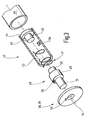
- Fig. 3
- eine vormontierte Baueinheit der Spanneinrichtung des Sonnenrollos nach Fig. 2 in einer perspektivischen Explosionsdarstellung, teilweise aufgebrochen, und
- Fig. 4
- eine Spanneinrichtung unter Verwendung einer Spiralfeder, in einer perspektivischen Explosionsdarstellung.
- Fig. 1
- a motor vehicle in a view from above;
- Fig. 2
- a schematic diagram of the invention sunscreen,
- Fig. 3
- a preassembled unit of the tensioning device of the sunblind of FIG. 2 in a perspective exploded view, partially broken, and
- Fig. 4
- a tensioning device using a spiral spring, in an exploded perspective view.
Fig. 1 zeigt in einer schematisierten Draufsicht eines Kombi-PKW 1. Zu Erkennen ist sein Dach 2, von dem an der Vorderkante zwei A-Säulen 3 und 4 ausgehen. Zwischen den beiden A-Säulen 3 und 4 befindet sich eine Windschutzscheibe 5, die an der Unterkante in eine Kühlerhaube 6 übergeht. Nach hinten folgen auf die beiden A-Säulen 3 und 4, B-Säulen 7 und 8, C-Säulen 9 und 10 sowie D-Säulen 11 und 12. Zwischen den Säulen 3...12 sind vordere Seitenscheiben 13, 14, hintere Seitenscheiben 15, 16 und Seitenscheiben des Kofferraums 17, 18 zu erkennen. Den Abschluss bildet eine Heckscheibe 19, die zwischen den beiden D-Säulen 11, 12 vorhanden ist.Fig. 1 shows in a schematic plan view of a station wagon 1. To recognize is its
Im vorderen Bereich des Daches 2 ist angrenzend an die Frontscheibe 5 eine Dachöffnung 20 enthalten, in der sich ein Dachfenster 21 befindet. Das Dachfenster 21 kann ein Glasschiebedach oder ein Glashubdach sein. Es kann sich auch um ein Glasdach handeln, das beide Funktionen miteinander vereint.In the front area of the
Unterhalb des Glasdaches 21 befindet sich ein Sonnenrollo 22, dessen Rollobahn 23 durch das Glasdach 21 zu erkennen ist. Die Rollobahn 23 endet an einer freien Kante 24, die etwa in der Mitte der Dachöffnung 20 steht.Below the
Der Aufbau des Sonnenrollos 22 ist in Fig. 2 schematisiert dargestellt.The structure of the
Zu dem Sonnenrollo 22 gehört eine Wickelwelle 25, die in dem Dachinnenraum, d.h. zwischen der äußeren Dachhaut der Rohkarosserie und dem Himmel drehbar gelagert ist. An der Wickelwelle 25 ist mit einer Kante die Rollobahn 23 befestigt, deren Zuschnitt etwa der Größe und der Form des Dachausschnitts 20 entspricht.Belonging to the
Im Falle der Verwendung von zwei getrennten nebeneinander liegenden Sonnenrollos sind dementsprechend zwei Rollobahnen vorhanden, die in derselben Weise angetrieben sind, wie dies nachstehend erläutert ist.In the case of using two separate side-by-side sunblinds, there are accordingly two blinds, which are driven in the same way, as explained below.
Die von der Wickelwelle 25 abliegende freie Kante 24 ist zu einer Schlaufe 26 geformt, durch die ein Spriegel 27 hindurch führt. Der Spriegel 27 steht endseits über und trägt dort Führungsstücke 28, 29, mit denen er in Führungsschienen 30 und 31 geführt ist. Die Führungsschienen 30 und 31 laufen parallel zu der Fahrzeuglängsachse neben den Seitenkanten der Dachöffnung 20, vorzugsweise dort in den Himmel integriert.The free from the winding
Die beiden Führungsschienen 30, 31 sind die in dieser Technik üblichen C-förmigen Schienen mit einer Nutenkammer 32, die sich in Richtung auf einen Nutenschlitz 33 öffnet. Die Nutenschlitze 33 der beiden Schienen 30, 31 öffnen sich aufeinander zu.The two
Zum besseren Verständnis sind die beiden Führungsschienen 30, 31 längs ihres Rückens aufgeschnitten und außerdem sind sie lediglich abschnittsweise dargestellt.For better understanding, the two
An dem von der Wickelwelle abliegenden Ende der Führungsschienen 30, 31 sind zwei Umlenkrollen 34 und 35 lose drehbar gelagert. Die Umlenkrollen 34, 35 dienen der Umlenkung von zwei Zugseilen 36, 37, die bei der praktischen Ausführung durch die Führungsschienen 30, 31 laufen und einends an dem Spriegel 27 verankert sind. Das andere Ende jedes Zugseils 36, 37 führt zu einer zugehörigen Seilscheibe 38, 39. Die beiden Seilscheiben 38, 39 sind koaxial zu der rohrförmigen Wickelwelle 25 neben deren Stirnenden drehbar gelagert. Sie sind gegenüber der Wickelwelle 25 drehbar.At the remote from the winding shaft end of the guide rails 30, 31, two
Jede Seilscheibe 38, 39 enthält eine Seilnut 40, die von Bordwänden begrenzt ist, um ein Herunterspringen des jeweils aufgewickelten Abschnitts des betreffenden Zugseils 36, 37 zu verhindern.Each
Zwischen jeder Seilscheibe 38, 39 und der Wickelwelle 25 ist eine zugehörige Spanneinrichtung 41 wirksam. Die beiden Spanneinrichtungen 41 sind baugleich, jedoch spiegelsymmetrisch. Ihr Aufbau wird nachstehend anhand von Fig.3 erläutert.Between each
Zu jeder Spanneinrichtung 41 gehört ein becherförmiges Gehäuse 42, dass sich aus einem rohrförmigen Mantel 43 und einem in diesem Rohrstück 43 verankerten Bodenstück 44 zusammensetzt. Von dem Bodenstück 44 geht ein Zentrierzapfen 45 aus, der in den Rohrabschnitt 43 hineinragt und zu diesem koaxial ist. Neben dem Zentrierzapfen 45 enthält das Bodenstück 44 eine Verankerungsbohrung 46. Das Bodenstück 44 bildet so ein Widerlager für eine Schraubenfeder 47, in die der Zentrierzapfen 45 hineinragt. Die Schraubenfeder 47 ist als Runddrahtfeder veranschaulicht. Bevorzugt wird zur Herstellung der Feder jedoch ein Draht mit rechteckigem Querschnitt verwendet, um eine möglichst gute Raumausnutzung zu erzielen. Die lange Seite des Rechtecks liegt etwa parallel zu dem Radius der Schraubenfederwindung.Each clamping
Das dem Bodenstück 44 benachbarte Ende der Feder 47 ist, wie dargestellt, achsparallel abgebogen und steckt im montierten Zustand in der Bohrung 46.The
In dem offenen Ende des becherförmigen Gehäuses 42 steckt drehbar eine Lagerwelle 48. Die Lagerwelle 48 weist einen Mittelteil 49 auf, das so bemessen ist, dass es mit geringem Radialspiel in dem becherförmigen Gehäuse 42 drehbar ist. Auf seiner vom Betrachter abgekehrten Rückseite geht das Mittelstück 49 in einen Zentrierzapfen 51 über, auf dem das benachbarte Ende der Schraubenfeder 47 sitzt. Zur Verankerung der Schraubenfeder 47 enthält das Mittelstück 50 eine Aufnahmebohrung, ähnlich der Bohrung 46, in die im montierten Zustand das achsparallel abgewinkelte Ende der Schraubenfeder 47 eingesteckt ist.In the open end of the cup-shaped
Auf der von dem Zentrierzapfen 50 abliegenden Seite trägt das Mittelstück 49 koaxial einen Lagerzapfen 51. Der Lagerzapfen 51 dient einerseits als Sitz für die bereits erwähnte Seilscheibe 38 bzw. 39. Sein über die Seilscheibe 38, 39 überstehendes Ende steckt in einer karosseriefesten Lagerbuchse, wie sie in Fig. 2 bei 52 bzw. 53 veranschaulicht sind.On the side remote from the centering
Hierzu ist der Lagerzapfen 51 deutlich länger, als es der Dicke der Seilscheibe 38, 39 entspricht.For this purpose, the bearing
Die Seilscheibe 38, 39 enthält eine Lagerbohrung 54, die stramm auf den Zapfen 21 passt. Seitlich versetzt neben der Bohrung 54 enthält jede Seilscheibe 38, 39 eine Mitnehmeröffnung 55, in die im montierten Zustand ein Mitnehmerzapfen 56 eingreift, der von dem Mittelstück 49 ausgeht und sich parallel neben dem Zapfen 51 erstreckt.The
Die Darstellung nach Fig. 3 ist vereinfacht insofern, als die erforderlichen Maßnahmen zum dauerhaften Verankern der Seilscheiben 38, 39 auf den Zapfen 51 ebenso wenig veranschaulicht sind, wie die Maßnahmen, die dazu dienen, die Lagerwelle 48 axial in dem Gehäuse 42 zu sichern. Schließlich sind auch jene Maßnahmen nicht veranschaulicht, die dazu dienen, die Feder 47 im vorgespannten Zustand zu sichern. Solche Maßnahmen sind beispielsweise in der auf die Anmelderin zurückgehenden Patentanmeldung DE 102 01 786 A1 erläutert ist, auf die hier ausdrücklich Bezug genommen ist.The illustration of FIG. 3 is simplified insofar as the measures required for permanently anchoring the
Das becherförmige Gehäuse 42 jeder Spanneinrichtung 41 ist drehfest mit der rohrförmigen Wickelwelle 25 verbunden. Das Gehäuse 42 enthält eine rechteckige Öffnung 58, in die während der Montage eine Nase oder eine Lasche eingedrückt wird, die einstückiger Bestandteil der Wickelwelle 25 ist.The cup-shaped
Die Wirkungsweise der Anordnung ist wie folgt:The operation of the arrangement is as follows:
Von beiden Enden der Wickelwelle 25 her wird je eine als selbstständige Einheit ausgeführte Spanneinrichtung 41 eingesteckt. Die beiden Spanneinrichtungen 41 unterscheiden sich voneinander lediglich hinsichtlich des Wickelsinns der jeweils verwendeten Schraubenfeder 47. Ansonsten sind die beiden Spanneinrichtungen 41 baugleich. Nach dem Einstecken der Gehäuse 42 werden diese in der Wickelwelle 25 verstemmt, indem Material in Gestalt einer Lasche oder Sicke aus der Wickelwelle 25 in die Öffnung 58 eingedrückt wird. Sodann wird jede Spanneinrichtung 41 um einige Umdrehungen aufgezogen, und beispielsweise, wie in der oben erwähnten Druckschrift beschrieben, gesichert. Sodann wird mit jeder Seilscheibe 38, 39 das zugehörige Zugseil 36, 37 einends verbunden und es wird eine entsprechende Zahl von Seilwindungen auf die betreffende Seilscheibe 38, 39 aufgelegt.From both ends of the winding
Mit der Wickelwelle 25 wird die Rollobahn 23 mit der entsprechenden Kante verklebt. Das so erhaltene Gebilde wird im Fahrzeug montiert, indem die Lagerzapfen 51 in die Lagerbuchsen 52, 53 eingefädelt werden. Die Zugseile werden sodann durch die Führungsschienen 30, 31, in die zuvor die Führungsstücke 28, 29 des Spriegels 27 eingesteckt wurden, hindurchgefädelt und um die zugehörige Umlenkrolle 34, 35 herumgeführt. Anschließend werden die noch freien Enden der Zugseile 36, 37 mit dem Spriegel 27 verbunden.With the winding
Nachdem die Montage abgeschlossen ist, werden die Sicherungen der Spanneinrichtungen 41 gezogen, damit die von der Spanneinrichtung 41 ausgehende Kraft frei werden kann. Es entsteht nun hierdurch ein Relativdrehmoment zwischen der Wickelwelle 25 einerseits und den beiden Seilscheiben 38. Das Drehmoment ist so gerichtet, dass es einerseits bestrebt ist, die Rollobahn 23 auf die Wickelwelle 25 aufzuwickeln, andererseits aber auch die Zugseile 36, 37 auf die Seilscheiben 38, 39 aufzuspulen. Auf diese Weise wird die Rollobahn 23 in dem nicht aufgewickelten Bereich zwischen der Wickelwelle 25 und dem Spriegel 27 gespannt gehalten. Die Spannkraft entspricht dem Drehmoment, das die beiden Spanneinrichtungen 41 erzeugen können.After assembly is complete, the fuses of the
Beim Ausfahren der Rollobahn 23 verändert sich der Ballendurchmesser, während pro Umdrehung der Seilscheibe etwa gleichviel Zugseil auf- oder abgewickelt wird. Dementsprechend kommt eine Relativdrehung zwischen der Wickelwelle 25 und den beiden Seilscheiben 38, 39 zustande. Diese Relativdrehung wird von den Spanneinrichtungen 41 aufgenommen, und zwar in jeder Betriebsstellung des Sonnenschutzrollos 22.When extending the
Andererseits gibt es nach außen hin keine freien Kräfte, so dass der Benutzer jederzeit mit Hilfe eines nicht weiter gezeigten Griffs im Bereich der freien Kante 24 von Hand das Sonnenrollo 22 vor der Öffnung 20 ausbreiten kann oder den Sonnenschutz zurückschieben kann, wobei die Rollobahn 23 selbsttätig auf der Wickelwelle 25 aufgewickelt wird.On the other hand, there are no free forces to the outside, so that the user at any time with the help of a handle not shown in the area of the
Die Kraft, die der Benutzer aufbringen muss, um die Rollobahn hin und her zu schieben ist im Wesentlichen nur jene Kraft, die notwendig ist, um die Führungsstücke 28, 29 durch die Führungsschiene 30, 31 gleiten zu lassen. Somit wird ein Sonnenrollo geschaffen, dass leicht von Hand zu betätigen ist. Außerdem ist die Montage wesentlich vereinfacht, weil kein gemeinsamer Federantrieb vorgesehen ist, um die beiden Seilscheiben 38, 39 mit der Wickelwelle 25 zu kuppeln. Vielmehr ist jede Seilscheibe für sich mit der Wickelwelle 25 verbunden, was die Montage erheblich vereinfacht, denn die Wickelwelle 25 hat eine beachtliche Längn entsprechend der Breite des Fahrzeugs im Dachbereich.The force that the user must apply to push the roller blind back and forth is essentially only that force necessary to slide the
Die Montage der Wickelwelle 25 kann noch vereinfacht werden, wenn beispielsweise die Lagerwelle 48 in axialer Richtung in dem Gehäuse 42 verschiebbar gelagert ist. Hierzu wird eine Schraubenfeder verwendet, die im entspannten Zustand die Lagerwelle 48 in axialer Richtung vorspannt und andererseits Platz lässt, damit die Lagerwelle 48 ein Stück weit in das Gehäuse 42 zurückgedrückt werden kann.The assembly of the winding
Anstelle einer Schraubenfeder 47 kann die kinematische Verbindung zwischen der Wickelwelle 25 und der Seilscheibe 38, 39 auch mit Hilfe einer Spiralfeder bewerkstelligt werden, wie dies in Fig. 4 schematisch angedeutet ist. Die Seilscheibe 38, 39 ist für sich becherförmig ausgeführt und nimmt, ähnlich einer Uhrwerksfeder, eine spiralförmige Feder 61 in ihrem Innenraum 62 auf. Die Spiralfeder 61 ist eine Blattfeder, deren außenliegendes Ende 63 in einer Nut 64 des Federgehäuses verankert ist. Das innenliegende Ende 65 sitzt in einem Radialschlitz 66 der modifizierten Lagerwelle 48. Die Lagerwelle 48 sitzt bei diesem Ausführungsbeispiel drehfest in der rohrförmigen Wickelwelle 25, so dass das Gehäuse 42 entbehrlich ist. Auf dem Lagerzapfen 51 steckt die becherförmige Seilscheibe 38, 39 drehbar, wodurch das gewünschte Drehmoment zwischen der Seilscheibe 38, 39 und der Wickelwelle 25 erzeugt werden kann.Instead of a
Bei einem Sonnenschutzrollo, insbesondere für Glasdächer, ist eine Wickelwelle vorhanden, zu der koaxial zwei Wickelscheiben angeordnet sind. Zwischen der Rollowelle und der jeweiligen Wickelscheibe sitzt ein Federglied, mit dessen Hilfe ein Relativdrehmoment zwischen diesen beiden Bauteilen erzeugt werden kann. An der Wickelwelle ist eine Rollobahn befestigt, deren freie Kante mit einem Zugseil verbunden ist, das um eine Umlenkeinrichtung zu der jeweiligen Wickelscheibe zurückführt. Mit Hilfe der Spanneinrichtung wird die Rollobahn zwischen der freien Kante und der Wickelwelle gespannt gehalten.In a sunblind, especially for glass roofs, a winding shaft is present, to the coaxial two winding discs are arranged. Between the roller shaft and the respective winding disk sits a spring member, with the aid of a relative torque between these two components can be generated. On the winding shaft a roller blind is attached, the free edge is connected to a pull rope, which leads back to a deflection device to the respective winding disk. With the help of the clamping device, the roller blind is kept taut between the free edge and the winding shaft.
Claims (16)
mit einer drehbar gelagerten Wickelwelle (25),
mit einer Rollobahn (23), die mit einer Kante an der Wickelwelle (25) befestigt ist und die eine freie Kante (24) aufweist,
mit einer ersten Spanneinrichtung (41), die kinematisch zwischen der Wickelwelle (25) und einer Wickelscheibe (38,39) liegt,
mit einer zweiten Spanneinrichtung (41), die kinematisch zwischen der Wickelwelle (25) und einer zweiten Wickelscheibe (38,38) liegt,
mit einem ersten linienförmigen Zugglied (36,37), das mit einem Ende an der ersten Wickelscheibe (38,39) festgelegt und mit dem anderen Ende mit der freien Kante (24) der Rollobahn (23) verbunden ist,
mit einem zweiten linienförmigen Zugglied (36,37), das mit einem Ende an der zweiten Wickelscheibe (38,39) festgelegt und mit dem anderen Ende mit der freien Kante (24) der Rollobahn (23) verbunden ist,
mit zwei Umlenkgliedern (34,35) die aus der Sicht der Wickelwelle (25) jenseits jener Stelle angeordnet sind in die die freie Kante (24) der Rollobahn (23) maximal bringbar ist, wobei um jedes Umlenkglied (34,35) das jeweils zugehörige Zugglied (36,37) herumläuft.Sun protection roller blind for glass roofs of motor vehicles,
with a rotatably mounted winding shaft (25),
with a roller blind web (23) which is fastened with one edge to the winding shaft (25) and which has a free edge (24),
with a first tensioning device (41), which lies kinematically between the winding shaft (25) and a winding disk (38, 39),
with a second tensioning device (41), which lies kinematically between the winding shaft (25) and a second winding disk (38, 38),
with a first line-shaped tension member (36, 37) which is fixed at one end to the first winding disk (38, 39) and at the other end to the free edge (24) of the roller blind (23),
with a second linear tension member (36, 37) fixed at one end to the second winding disk (38, 39) and connected at the other end to the free edge (24) of the roller blind (23),
with two deflecting members (34,35) which are arranged from the view of the winding shaft (25) beyond that point into which the free edge (24) of the roller blind (23) can be brought maximum, with each deflecting member (34,35) each associated tension member (36,37) runs around.
Applications Claiming Priority (1)
| Application Number | Priority Date | Filing Date | Title |
|---|---|---|---|
| DE200410038756 DE102004038756A1 (en) | 2004-08-09 | 2004-08-09 | Sun protection roller blind for glass roofs |
Publications (1)
| Publication Number | Publication Date |
|---|---|
| EP1626152A1 true EP1626152A1 (en) | 2006-02-15 |
Family
ID=35148789
Family Applications (1)
| Application Number | Title | Priority Date | Filing Date |
|---|---|---|---|
| EP05016148A Withdrawn EP1626152A1 (en) | 2004-08-09 | 2005-07-26 | Solar protection device for glass roof |
Country Status (2)
| Country | Link |
|---|---|
| EP (1) | EP1626152A1 (en) |
| DE (1) | DE102004038756A1 (en) |
Cited By (11)
| Publication number | Priority date | Publication date | Assignee | Title |
|---|---|---|---|---|
| WO2006058527A1 (en) * | 2004-12-01 | 2006-06-08 | Webasto Ag | Darkening device for vehicles |
| EP1870271A1 (en) * | 2006-06-20 | 2007-12-26 | HS Products Engineering GmbH | Roller blind for a vehicle window |
| EP2025546A1 (en) * | 2007-08-14 | 2009-02-18 | Inalfa Roof Systems Group B.V. | Sun screen assembly |
| EP2058158A1 (en) * | 2007-11-06 | 2009-05-13 | Inalfa Roof Systems Group B.V. | Tensioning device and sunscreen assembly provided therewith |
| FR2925102A1 (en) * | 2007-12-17 | 2009-06-19 | Peugeot Citroen Automobiles Sa | Shading device for e.g. window glass, of car, has roller comprising curved tube fixed with respect to support and flexible tube placed around curved tube, where flexible tube forms rotation free element of roller |
| WO2011086084A1 (en) * | 2010-01-13 | 2011-07-21 | In2P Gmbh | Roller blind device |
| DE102013221558A1 (en) * | 2013-10-23 | 2015-04-23 | Bos Gmbh & Co. Kg | net device |
| CN107234952A (en) * | 2017-06-21 | 2017-10-10 | 安徽省地坤汽车天窗科技有限公司 | A kind of roller blind device of outward opening panoramic sunroof of automobile |
| CN109017229A (en) * | 2018-09-07 | 2018-12-18 | 威海瑞琦汽车制造股份有限公司 | A kind of filter device for caravan skylight |
| CN110094154A (en) * | 2019-05-27 | 2019-08-06 | 北京东方凌云科技有限公司 | Glass curtain wall and door and window with transparent sun protection heat-insulating and energy-saving roller shutter |
| CN112829552A (en) * | 2019-11-25 | 2021-05-25 | 宝适汽车部件(太仓)有限公司 | Shading device for side window of motor vehicle |
Families Citing this family (4)
| Publication number | Priority date | Publication date | Assignee | Title |
|---|---|---|---|---|
| EP1905646B1 (en) | 2006-09-27 | 2011-04-13 | BOS GmbH & Co. KG | Luggage compartment with automatic opening |
| DE102008016909B4 (en) * | 2008-03-25 | 2010-12-02 | Bos Gmbh & Co. Kg | window treatment |
| DE202012000995U1 (en) | 2012-01-31 | 2012-04-24 | Lisa Dräxlmaier GmbH | Roller blind with tensioning device |
| CN105522899A (en) * | 2016-01-27 | 2016-04-27 | 江苏德福来汽车部件有限公司 | Sunshade curtain capable of being opened and closed at any time |
Citations (7)
| Publication number | Priority date | Publication date | Assignee | Title |
|---|---|---|---|---|
| US3180401A (en) * | 1962-03-02 | 1965-04-27 | Thomas F Gambon | Shade |
| FR2604203A2 (en) * | 1981-04-28 | 1988-03-25 | Franciaflex | Blind with lateral guiding and long extension such as a sunshade for glasshouses, verandas and the like |
| US4887660A (en) * | 1988-06-30 | 1989-12-19 | Frommelt Industries, Inc. | Roll-up door |
| US5271446A (en) * | 1993-03-02 | 1993-12-21 | Hwang Chyi Ming | Multi-purpose automatically rewindable sun-shade |
| EP1034954A2 (en) * | 1999-03-11 | 2000-09-13 | Webasto Vehicle Systems International GmbH | Roller sun-blind for vehicle roof |
| EP1319772A1 (en) * | 2001-12-14 | 2003-06-18 | MHZ SONNENSCHUTZTECHNIK GmbH | Positive return awning with one sided length compensating device |
| DE10201786A1 (en) | 2002-01-17 | 2003-08-07 | Bos Gmbh | Pre-assembled roller blind unit |
-
2004
- 2004-08-09 DE DE200410038756 patent/DE102004038756A1/en not_active Ceased
-
2005
- 2005-07-26 EP EP05016148A patent/EP1626152A1/en not_active Withdrawn
Patent Citations (7)
| Publication number | Priority date | Publication date | Assignee | Title |
|---|---|---|---|---|
| US3180401A (en) * | 1962-03-02 | 1965-04-27 | Thomas F Gambon | Shade |
| FR2604203A2 (en) * | 1981-04-28 | 1988-03-25 | Franciaflex | Blind with lateral guiding and long extension such as a sunshade for glasshouses, verandas and the like |
| US4887660A (en) * | 1988-06-30 | 1989-12-19 | Frommelt Industries, Inc. | Roll-up door |
| US5271446A (en) * | 1993-03-02 | 1993-12-21 | Hwang Chyi Ming | Multi-purpose automatically rewindable sun-shade |
| EP1034954A2 (en) * | 1999-03-11 | 2000-09-13 | Webasto Vehicle Systems International GmbH | Roller sun-blind for vehicle roof |
| EP1319772A1 (en) * | 2001-12-14 | 2003-06-18 | MHZ SONNENSCHUTZTECHNIK GmbH | Positive return awning with one sided length compensating device |
| DE10201786A1 (en) | 2002-01-17 | 2003-08-07 | Bos Gmbh | Pre-assembled roller blind unit |
Cited By (14)
| Publication number | Priority date | Publication date | Assignee | Title |
|---|---|---|---|---|
| WO2006058527A1 (en) * | 2004-12-01 | 2006-06-08 | Webasto Ag | Darkening device for vehicles |
| EP1870271A1 (en) * | 2006-06-20 | 2007-12-26 | HS Products Engineering GmbH | Roller blind for a vehicle window |
| EP2025546A1 (en) * | 2007-08-14 | 2009-02-18 | Inalfa Roof Systems Group B.V. | Sun screen assembly |
| CN101428549B (en) * | 2007-11-06 | 2013-01-30 | 银娜珐天窗系统集团股份有限公司 | Tensioning device and sunscreen assembly provided therewith |
| EP2058158A1 (en) * | 2007-11-06 | 2009-05-13 | Inalfa Roof Systems Group B.V. | Tensioning device and sunscreen assembly provided therewith |
| US9227488B2 (en) | 2007-11-06 | 2016-01-05 | Inalfa Roof Systems Group B.V. | Tensioning device and sunscreen assembly provided therewith |
| FR2925102A1 (en) * | 2007-12-17 | 2009-06-19 | Peugeot Citroen Automobiles Sa | Shading device for e.g. window glass, of car, has roller comprising curved tube fixed with respect to support and flexible tube placed around curved tube, where flexible tube forms rotation free element of roller |
| WO2011086084A1 (en) * | 2010-01-13 | 2011-07-21 | In2P Gmbh | Roller blind device |
| DE102013221558A1 (en) * | 2013-10-23 | 2015-04-23 | Bos Gmbh & Co. Kg | net device |
| DE102013221558B4 (en) * | 2013-10-23 | 2015-05-28 | Bos Gmbh & Co. Kg | net device |
| CN107234952A (en) * | 2017-06-21 | 2017-10-10 | 安徽省地坤汽车天窗科技有限公司 | A kind of roller blind device of outward opening panoramic sunroof of automobile |
| CN109017229A (en) * | 2018-09-07 | 2018-12-18 | 威海瑞琦汽车制造股份有限公司 | A kind of filter device for caravan skylight |
| CN110094154A (en) * | 2019-05-27 | 2019-08-06 | 北京东方凌云科技有限公司 | Glass curtain wall and door and window with transparent sun protection heat-insulating and energy-saving roller shutter |
| CN112829552A (en) * | 2019-11-25 | 2021-05-25 | 宝适汽车部件(太仓)有限公司 | Shading device for side window of motor vehicle |
Also Published As
| Publication number | Publication date |
|---|---|
| DE102004038756A1 (en) | 2006-02-23 |
Similar Documents
| Publication | Publication Date | Title |
|---|---|---|
| EP1626152A1 (en) | Solar protection device for glass roof | |
| EP1182066B1 (en) | Vehicle with roller blind in the roof | |
| DE10124100C1 (en) | Roller blind device for a transparent roof element | |
| DE10232536B4 (en) | net device | |
| DE102010018259B4 (en) | Vehicle roller blind assembly, assembly with a vehicle blind assembly, and roof assembly | |
| WO2006034690A1 (en) | Blind arrangement for a motor vehicle | |
| EP2062780B1 (en) | Roller blind system | |
| DE102007012259A1 (en) | Sun protection roller blind for motor vehicles | |
| EP1747923A2 (en) | Window roller blind with non-profiled thrust members | |
| DE202004014652U1 (en) | Door for a vehicle comprises a window blind with a blind path which moves parallel to the window pane using a mechanism a part of which is guided on the window lifter guide rail | |
| DE19834777C2 (en) | Roller blind, in particular sun protection roller blind for the transparent roof window of a motor vehicle | |
| EP3142878B1 (en) | Roller blind arrangement having lateral guidance | |
| WO2016198194A1 (en) | Roller blind arrangement with driving devices for laterally guiding a roller blind web | |
| DE102015106528A1 (en) | Vehicle window shade with cable pull concept and drive of the cable pull via toothed belt | |
| DE10322709B3 (en) | Sun blind arrangement for a vehicle roof and vehicle roof with such a sunshade blind arrangement | |
| DE10215322A1 (en) | Sun protection roller blind for side windows in motor vehicles has flexible winder shaft with roller length to prevent sun glare while covering minimum part of window | |
| DE102007039214A1 (en) | Sun protection device for transparent roof area of motor vehicle, has traction device designed as flexible pull cable or pull rope with reduced dimensional stability, for supporting closing movement of blind to close roof area | |
| WO2006063565A1 (en) | Blind for a vehicle window | |
| EP0529591B1 (en) | Roller blind, preferably for vehicle rear windows | |
| DE10063056A1 (en) | Winding type sun shade device for sunroof apparatus of e.g. motor vehicle, has tensile force control device which makes tensile force of sheet adjustable and includes brackets and shape retaining component | |
| DE202007004175U1 (en) | vehicle blind | |
| WO2009033981A1 (en) | Adjustment device for a cover device in a motor vehicle | |
| DE102008012434A1 (en) | Module assembly for installation in a motor vehicle | |
| DE10216186A1 (en) | Sun protection roller blind for windows in motor vehicles has roller length of self-supporting material and tension cable between blind layers, to eliminate need for side guide rails | |
| DE102005056608A1 (en) | Roller blind device for sunroof of motor vehicle, has web, which can be winded by winding device and includes two winding rolls that can be rotatably driven independent of one another and are arranged in region of longitudinal edges of web |
Legal Events
| Date | Code | Title | Description |
|---|---|---|---|
| PUAI | Public reference made under article 153(3) epc to a published international application that has entered the european phase |
Free format text: ORIGINAL CODE: 0009012 |
|
| AK | Designated contracting states |
Kind code of ref document: A1 Designated state(s): AT BE BG CH CY CZ DE DK EE ES FI FR GB GR HU IE IS IT LI LT LU LV MC NL PL PT RO SE SI SK TR |
|
| AX | Request for extension of the european patent |
Extension state: AL BA HR MK YU |
|
| 17P | Request for examination filed |
Effective date: 20060405 |
|
| 17Q | First examination report despatched |
Effective date: 20060622 |
|
| AKX | Designation fees paid |
Designated state(s): AT BE BG CH CY CZ DE DK EE ES FI FR GB GR HU IE IS IT LI LT LU LV MC NL PL PT RO SE SI SK TR |
|
| GRAP | Despatch of communication of intention to grant a patent |
Free format text: ORIGINAL CODE: EPIDOSNIGR1 |
|
| STAA | Information on the status of an ep patent application or granted ep patent |
Free format text: STATUS: THE APPLICATION IS DEEMED TO BE WITHDRAWN |
|
| 18D | Application deemed to be withdrawn |
Effective date: 20130528 |