EP1627700A2 - Keyless chuck with automatic and manual locking - Google Patents
Keyless chuck with automatic and manual locking Download PDFInfo
- Publication number
- EP1627700A2 EP1627700A2 EP05017487A EP05017487A EP1627700A2 EP 1627700 A2 EP1627700 A2 EP 1627700A2 EP 05017487 A EP05017487 A EP 05017487A EP 05017487 A EP05017487 A EP 05017487A EP 1627700 A2 EP1627700 A2 EP 1627700A2
- Authority
- EP
- European Patent Office
- Prior art keywords
- jaws
- sleeve
- relative
- chuck
- actuating member
- Prior art date
- Legal status (The legal status is an assumption and is not a legal conclusion. Google has not performed a legal analysis and makes no representation as to the accuracy of the status listed.)
- Granted
Links
Images


Classifications
-
- B—PERFORMING OPERATIONS; TRANSPORTING
- B23—MACHINE TOOLS; METAL-WORKING NOT OTHERWISE PROVIDED FOR
- B23B—TURNING; BORING
- B23B31/00—Chucks; Expansion mandrels; Adaptations thereof for remote control
- B23B31/02—Chucks
- B23B31/10—Chucks characterised by the retaining or gripping devices or their immediate operating means
- B23B31/12—Chucks with simultaneously-acting jaws, whether or not also individually adjustable
- B23B31/1207—Chucks with simultaneously-acting jaws, whether or not also individually adjustable moving obliquely to the axis of the chuck in a plane containing this axis
- B23B31/123—Chucks with simultaneously-acting jaws, whether or not also individually adjustable moving obliquely to the axis of the chuck in a plane containing this axis with locking arrangements
-
- B—PERFORMING OPERATIONS; TRANSPORTING
- B23—MACHINE TOOLS; METAL-WORKING NOT OTHERWISE PROVIDED FOR
- B23B—TURNING; BORING
- B23B31/00—Chucks; Expansion mandrels; Adaptations thereof for remote control
- B23B31/02—Chucks
- B23B31/10—Chucks characterised by the retaining or gripping devices or their immediate operating means
- B23B31/12—Chucks with simultaneously-acting jaws, whether or not also individually adjustable
- B23B31/1207—Chucks with simultaneously-acting jaws, whether or not also individually adjustable moving obliquely to the axis of the chuck in a plane containing this axis
- B23B31/1238—Jaws movement actuated by a nut with conical screw-thread
-
- B—PERFORMING OPERATIONS; TRANSPORTING
- B23—MACHINE TOOLS; METAL-WORKING NOT OTHERWISE PROVIDED FOR
- B23B—TURNING; BORING
- B23B2231/00—Details of chucks, toolholder shanks or tool shanks
- B23B2231/38—Keyless chucks for hand tools
-
- Y—GENERAL TAGGING OF NEW TECHNOLOGICAL DEVELOPMENTS; GENERAL TAGGING OF CROSS-SECTIONAL TECHNOLOGIES SPANNING OVER SEVERAL SECTIONS OF THE IPC; TECHNICAL SUBJECTS COVERED BY FORMER USPC CROSS-REFERENCE ART COLLECTIONS [XRACs] AND DIGESTS
- Y10—TECHNICAL SUBJECTS COVERED BY FORMER USPC
- Y10S—TECHNICAL SUBJECTS COVERED BY FORMER USPC CROSS-REFERENCE ART COLLECTIONS [XRACs] AND DIGESTS
- Y10S279/00—Chucks or sockets
- Y10S279/902—Keyless type socket
-
- Y—GENERAL TAGGING OF NEW TECHNOLOGICAL DEVELOPMENTS; GENERAL TAGGING OF CROSS-SECTIONAL TECHNOLOGIES SPANNING OVER SEVERAL SECTIONS OF THE IPC; TECHNICAL SUBJECTS COVERED BY FORMER USPC CROSS-REFERENCE ART COLLECTIONS [XRACs] AND DIGESTS
- Y10—TECHNICAL SUBJECTS COVERED BY FORMER USPC
- Y10T—TECHNICAL SUBJECTS COVERED BY FORMER US CLASSIFICATION
- Y10T279/00—Chucks or sockets
- Y10T279/10—Expanding
- Y10T279/1004—Collet type
- Y10T279/1008—Fixed jaws and moving cam
-
- Y—GENERAL TAGGING OF NEW TECHNOLOGICAL DEVELOPMENTS; GENERAL TAGGING OF CROSS-SECTIONAL TECHNOLOGIES SPANNING OVER SEVERAL SECTIONS OF THE IPC; TECHNICAL SUBJECTS COVERED BY FORMER USPC CROSS-REFERENCE ART COLLECTIONS [XRACs] AND DIGESTS
- Y10—TECHNICAL SUBJECTS COVERED BY FORMER USPC
- Y10T—TECHNICAL SUBJECTS COVERED BY FORMER US CLASSIFICATION
- Y10T279/00—Chucks or sockets
- Y10T279/17—Socket type
- Y10T279/17615—Obliquely guided reciprocating jaws
- Y10T279/17623—Threaded sleeve and jaw
- Y10T279/17632—Conical sleeve
-
- Y—GENERAL TAGGING OF NEW TECHNOLOGICAL DEVELOPMENTS; GENERAL TAGGING OF CROSS-SECTIONAL TECHNOLOGIES SPANNING OVER SEVERAL SECTIONS OF THE IPC; TECHNICAL SUBJECTS COVERED BY FORMER USPC CROSS-REFERENCE ART COLLECTIONS [XRACs] AND DIGESTS
- Y10—TECHNICAL SUBJECTS COVERED BY FORMER USPC
- Y10T—TECHNICAL SUBJECTS COVERED BY FORMER US CLASSIFICATION
- Y10T279/00—Chucks or sockets
- Y10T279/32—Means to prevent jaw loosening
-
- Y—GENERAL TAGGING OF NEW TECHNOLOGICAL DEVELOPMENTS; GENERAL TAGGING OF CROSS-SECTIONAL TECHNOLOGIES SPANNING OVER SEVERAL SECTIONS OF THE IPC; TECHNICAL SUBJECTS COVERED BY FORMER USPC CROSS-REFERENCE ART COLLECTIONS [XRACs] AND DIGESTS
- Y10—TECHNICAL SUBJECTS COVERED BY FORMER USPC
- Y10T—TECHNICAL SUBJECTS COVERED BY FORMER US CLASSIFICATION
- Y10T29/00—Metal working
- Y10T29/49—Method of mechanical manufacture
- Y10T29/49998—Work holding
-
- Y—GENERAL TAGGING OF NEW TECHNOLOGICAL DEVELOPMENTS; GENERAL TAGGING OF CROSS-SECTIONAL TECHNOLOGIES SPANNING OVER SEVERAL SECTIONS OF THE IPC; TECHNICAL SUBJECTS COVERED BY FORMER USPC CROSS-REFERENCE ART COLLECTIONS [XRACs] AND DIGESTS
- Y10—TECHNICAL SUBJECTS COVERED BY FORMER USPC
- Y10T—TECHNICAL SUBJECTS COVERED BY FORMER US CLASSIFICATION
- Y10T408/00—Cutting by use of rotating axially moving tool
- Y10T408/94—Tool-support
- Y10T408/95—Tool-support with tool-retaining means
- Y10T408/953—Clamping jaws
Landscapes
- Engineering & Computer Science (AREA)
- Mechanical Engineering (AREA)
- Gripping On Spindles (AREA)
- Lock And Its Accessories (AREA)
- Manipulator (AREA)
- Sealing Of Jars (AREA)
Abstract
Description
- The present invention relates to keyless chucks and, more particularly to keyless chucks with an automatic axial lock.
- Keyless chucks operable to retain a work piece therein by rotational movement of an outer sleeve relative to the body of the chuck is known. Many of these keyless chucks incorporate a locking feature to prevent the sleeve from opening the chuck during use. One type of locking feature is an automatic locking feature wherein as the jaws are tightened about the work piece, the sleeve, upon receiving a tightening torque in excess of a predetermined value, will lock or detent into a locked position that inhibits loosening of the chuck. This automatic locking feature provides for a quick and easy way of locking the work piece in the chuck. This automatic locking feature, however, may open during use in certain situations, such as abrupt stall. high vibration and when the sleeve rubs on an object while working in a tight space. Thus, while this type of automatic locking feature provides for a quick and easy way of securing a work piece in a chuck, it only provides moderate performance and may be susceptible to opening during use.
- A second type of locking feature that can be utilized is a manual locking feature. With this type of locking feature, a user is required to tighten the chuck onto the work piece and then manually lock the chuck sleeve via axial movement of the sleeve, or a connected component, with respect to the body. This type of locking chuck provides excellent performance in that the locking sleeve is prevented from loosening during operation by being rotationally fixed relative to the body. The use of the manually locking feature, however, adds an extra step to the use of the tool incorporating the chuck. Thus, while greater performance can be achieved, the use of such a chuck is more time consuming.
- Thus, the current keyless locking chucks require a choice between utilizing one that incorporates an automatic lock or one that incorporates a manual locking feature. Accordingly, when selecting a chuck, a trade off must be made between choosing one that is quicker to operate but provides a less secure locking feature and may loosen during use and choosing one that provides superior locking performance but requires an additional step to achieve this benefit.
- The inventors of the present invention have developed a new and novel approach to address the tradeoffs required in prior art keyless chucks. The inventors have developed a new keyless chuck that incorporates both an automatic locking feature and a manual locking feature. The chuck can be operated with just the automatic locking feature during situations when the quick securing of a work piece to the chuck is desirable and the additional protection of the manual locking feature is not necessary. When the additional protection provided by the manual locking feature is needed and the extra step associated with performing the manual locking feature is desired, the chuck can also be manually locked in place. Thus, the keyless chuck of the present invention provides the benefits of both an automatic locking feature and a manual locking feature without requiring a tradeoff between the two types of locking features. Furthermore, the present chuck allows for utilizing strictly the automatic locking feature or utilizing the automatic locking feature in conjunction with the manual locking feature.
- A chuck according to the principles of the present invention includes moveable jaws operable to selectively retain a work piece. There is an actuating member operable to cause the jaws to move when the actuating member rotates relative to the jaws. Movement of the jaws corresponds to tightening and loosening of the jaws. A first locking feature is operable to selectively prevent the actuating member from rotating relative to the jaws. The second locking feature is operable to inhibit the actuating member from rotating relative to the jaws. The second locking feature inhibits loosening of the jaws after a tightening force exceeding a predetermined value has been imparted between the actuating member and a component of the second locking feature.
- In another aspect of the present invention, a method of securing a work piece in a chuck is disclosed. The method includes: (1) positioning the work piece between jaws of the chuck; (2) rotating an actuating member relative to the jaws to tighten the jaws to the work piece; (3) automatically inhibiting loosening rotation of the actuating member with a first locking member after a tightening force exceeding a predetermined value is imparted between the actuating member and the first locking member; and (4) rotationally locking the actuating member relative to the jaws with a second locking member.
- Further areas of applicability of the present invention will become apparent from the detailed description provided hereinafter. It should be understood that the detailed description and speafic examples, while indicating the preferred embodiment of the invention, are intended for purposes of illustration only and are not intended to limit the scope of the invention.
- The present invention will become more fully understood from the detailed description and the accompanying drawings, wherein:
- Figure 1 is a side elevation view of a keyless chuck according to the principles of the present invention utilized on a power tool;
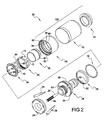
- Figure 2 is an exploded perspective view of the components of the chuck of Figure 1;
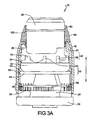
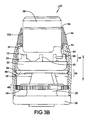
- Figures 3A and B show a partial cross-sectional view of the chuck of Figure 1 with the automatic locking feature engaged and a manual locking feature respectively disengaged and engaged;
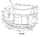
- Figures 4A and B are fragmented partial sectional views of a portion of the chuck of Figure 1 showing the engagement between the ratcheting mechanism and the inner sleeve with the automatic locking feature engaged and the manual locking feature respectively disengaged and engaged;
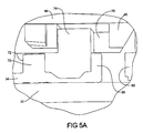
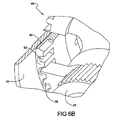
- Figures 5A and B are fragmented partial sectional views of a portion of the chuck of Figure 1 showing the engagement between the nut, the inner sleeve and the ratcheting mechanism with the automatic locking feature engaged and the manual locking feature respectively disengaged and engaged; and
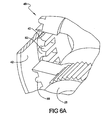
- Figures 6A and B are fragmented partial sectional views of a portion of the chuck of Figure 1 showing a portion of the manual locking feature in a respective disengaged and engaged position.
- The following description of the preferred embodiment(s) is merely exemplary in nature and is in no way intended to limit the invention, its application, or uses.
- Referring to Figure 1, a
keyless chuck 20 according to the principles of the present invention, is shown attached to apower tool 22, such as a drill or a like. An exploded view ofchuck 20 is shown in Figure 2. Chuck 20 includes anend cap 24, threejaws 26, abody 28, aretaining cup 30,loose ball bearings 32, an automatic locking andratcheting mechanism 34, anut 26, aninner nose 38, aninner sleeve 40, anouter sleeve 42, and anouter nose 44. These components ofchuck 20 are assembled together and enablechuck 20 to selectively retain a work piece and to impart a desired movement thereto via operation ofpower tool 22. - Referring now to Figures 3A and B,
chuck 20 includes an automatic locking feature generally indicated as 46.Automatic locking feature 46 operates to lockchuck 20 in a tightened position and inhibits a loosening ofchuck 20.Automatic locking feature 46 includes engagement between the automatic locking and ratcheting mechanism 34 (hereinafter referred to as ratcheting mechanism) andinner sleeve 40, as described in more detail below. Chuck 20 also includes a manual locking feature, generally indicated as 48.Manual locking feature 48 is operable to rotationally lockinner sleeve 40 tobody 28 such that relative rotation therebetween is prevented.Manual locking feature 48 allows selective engagement betweeninner sleeve 40 andbody 28, as shown in Figures 6A and B, by axially movinginner sleeve 40 relative tobody 28, as described in more detail below. Chuck 20 also includes a retaining feature generally indicated as 50. Retainingfeature 50 inhibits axial movement ofinner sleeve 40 relative tobody 28 and works in conjunction withmanual locking feature 48, as described in more detail below. - Jaws 26 are disposed around
body 28 inguides 52. Eachjaw 26 hasouter threads 54 that engage withintemal threads 55 onnut 36.Jaws 26 move axially along a center line axis (not shown) ofguides 52 relative tobody 28 asnut 36 rotates relative tobody 28.Jaws 26 are preferably made of metal, such as steel. -
Body 28 has three sets ofteeth 56 extending radially outwardly.Teeth 56 are spaced apart along the outer surface ofbody 28. Teeth 56 form a portion ofmanual locking feature 48 and can be engaged with complementary teeth oninner sleeve 40 to rotationally fixinner sleeve 40 andbody 28 together such that relative rotation therebetween is prevented, as described in more detail below.Body 28 also includes a radially extendingannular projection 58 that engages with complementary annular recesses ininner sleeve 40 to inhibit axial movement ofinner sleeve 40 relative tobody 28 thereby preventing or minimizing the accidental unlocking ofmanual locking feature 48, as described in more detail below. The engagement betweenannular protection 58 and the complementary recesses oninner sleeve 40form retaining feature 50.Body 28 is preferably made of metal, such as steel. - Referring now to Figures 2 and 4, retaining
cup 30 is disposed aroundbody 28. Radially inwardly extending projections ortabs 60 oncup 30 engage with complementary recesses onbody 28 to rotationally fixcup 30 tobody 28 such that relative rotation therebetween is prohibited.Cup 30 includes a track or race forbearings 32 to reside in and roll around during loosening and tightening ofchuck 20.Cup 30 also includes a plurality of ratcheting steps orteeth 62 that engage withratcheting mechanism 34 to provide an audible indication of the tightening ofchuck 20, as described in more detail below.Cup 30 is preferably made of steel. - Referring to Figures 2, 3 and 4,
ratcheting mechanism 34 is disposed aroundbody 28. Ratchetingmechanism 34 is capable of rotation relative tobody 28. Ratchetingmechanism 34 includes a track or race that faces the track oncup 30 and engages withbearings 32 disposed therebetween.Bearings 32 facilitate relative rotation between ratchetingmechanism 34 andbody 28. Ratchetingmechanism 34 has three sets of arms, generally indicated as 64, that extend axially and radially outwardly and are spaced apart along ratchetingmechanism 34. As shown in Figures 3 and 4, each set ofarms 64 includes a ratchetingarm 66 and a lockingarm 68. Each ratchetingarm 66 engages with a recess andinner sleeve 40 and with ratchetingsteps 62 incup 30 to provide an audible clicking aschuck 20 is being tightened, as described below. Each lockingarm 68 engages with a pair of recesses ininner sleeve 40 to allowinner sleeve 40 to rotateratcheting mechanism 34 to tighten and loosenchuck 20. Lockingarm 68 functions to automatically lockchuck 20 in a tightened state once a torque applied byinner sleeve 40 to ratchetingmechanism 34 exceeds a predetermined value, as discussed below. Ratchetingmechanism 34 is preferably made of metal, such as stamped spring steel. - Referring now to Figures 2, 3 and 5,
ratcheting mechanism 34 includes axially extending projections ortabs 70 that engage withrecesses 72 onnut 36 to rotationallyfix ratcheting mechanism 34 tonut 36 such that relative rotation therebetween is not possible. - Referring now to Figures 2 and 5,
nut 36 is disposed onbody 28 withthreads 55 engaged withthreads 54 onjaws 26.Nut 36 is capable of rotation relative tobody 28 andjaws 26.Nut 36 includes axially extending projections ortabs 74 that engage withrecesses 76 in the inner surface ofinner sleeve 40.Tabs 74 are narrower thanrecesses 76 and allow for a limited range of relative rotation betweennut 36 andinner sleeve 40. This limited relative rotation allows for lockingarm 68 to lock and unlockchuck 20 in the tightened state, as described in more detail below. Rotation ofnut 36 relative tobody 28 causesjaws 26 to move in and out ofchuck 20 to grip and release a work piece, as is known in the art.Nut 36 is preferably made of metal, such as powered metal. - Referring now to Figures 2 and 3,
inner nose 38 is pressed ontobody 28 and is rotationally and axially fixed thereto.Jaws 26 extend out of and retract intoinner nose 38 when tightening and looseningchuck 20.Inner nose 38 axially securescup 30,ratcheting mechanism 34 andnut 36 relative tobody 28.Inner nose 38 includes a radially outwardly extendingannular projection 80 that, as shown in Figures 3A and B, limits forward axial movement ofouter nose 44.Inner nose 30 is preferably made of metal, such as steel. - Referring now to Figures 2-6,
inner sleeve 40 is disposed aroundbody 28 and is axially moveable between an unlocked position (Figures 3A, 4A, 5A and 6A) and a locked position (Figures 3B, 4B, 5B and 6B) relative tobody 28. When in the unlocked position,inner sleeve 40 can rotate relative tobody 28. When in the locked position,inner sleeve 40 is rotationally fixed tobody 28 and relative rotation therebetween is prevented. The inner surface ofinner sleeve 40 includes a plurality of radially inwardly extendingteeth 82 that can be selectively engaged withteeth 56 onbody 28, via axial movement ofinner sleeve 40 relative tobody 28, to rotationally lockinner sleeve 40 tobody 28 such that relative rotation therebetween is prevented. Engagement ofteeth 82 withteeth 56 corresponds to the locked position ofinner sleeve 40.Teeth 38 oninner sleeve 40 andteeth 56 andbody 28 formmanual locking feature 48.Inner sleeve 40 is preferably made of a polymer, such as a glass filled nylon. Preferably, the nylon contains at least 30% glass by weight. - As best seen in Figures 3A and B, the inner surface of
inner sleeve 40 includes a front and rearannular recess Recesses annular projection 58 onbody 28 to inhibit axial movement ofinner sleeve 40 relative tobody 28. Inhibiting the relative axial movement prevents or minimizes accidental locking and unlocking ofmanual locking feature 48. The inhibition is overcome by application of an axial force sufficient to overcome the engagement betweenprojection 58 and recesses 84, 86. Front andrear recesses 84. 86 oninner sleeve 40 andannular projection 58 onbody 28form retaining feature 50. When in the unlocked position, as shown in Figure 3A,projection 58 is disposed withinrear recess 86. When in the locked position, as shown in Figure 3B,projection 58 is disposed infront recess 84. The use ofannular projection 58 is advantageous in that it provides a 360 degree engagement withrecesses projection 58 andfront recesses - Referring now to Figures 4A and B,
inner sleeve 40 includes 3 sets of axially extending recesses that engage with three sets ofarms 64 of ratchetingmechanism 34. Each set of recesses indudes aratchet recess 88, a loosening/opening recess 90, and a tightening orclosing recess 92.Ratchet recess 88 includes a tightening/closing ramp 94 and a loosening/opening ramp 96.Ratchet arm 66 will ride along tighteningramp 94 wheninner sleeve 40 is being rotated to tightenchuck 20 and will ride along looseningramp 96 wheninner sleeve 40 is being rotated to loosenchuck 20. The shape or slope of looseningramp 96causes ratcheting arm 66 to move radially inwardly and disengage from ratchetsteps 62 such that no audible clicking will be heard during the loosening ofchuck 20. - A jump or
projection 98 is disposed between loosening and tighteningrecesses arm 68 will ride within looseningrecess 90 and press againstjump 98 whileinner sleeve 40 is being rotated to tightenchuck 20. This interaction causesratchet mechanism 34 to drive rotation ofnut 36 to tightenjaws 26 andchuck 20. When the torque betweeninner sleeve 40 and lockingarm 68 exceeds a predetermined value (as determined by such things as the height and slope ofjump 98, the friction betweenjump 98 and lockingarm 68, and the spring rate of locking arm 68) lockingarm 68 will jump overjump 98 and into tighteningrecess 94. The movement of lockingarm 68 into tighteningramp 94 causes a single loud audible click or noise indicating thatchuck 20 is now fully tightened. The jumping of lockingarm 68 overjump 98 results in a limited relative rotation betweeninner sleeve 40 andnut 36. Wheninner sleeve 40 is subsequently rotated to loosenchuck 20, lockingarm 68 will jump back overjump 98 and into looseningrecess 90 and drive rotation of ratchetingmechanism 34 which in turn drives rotation ofnut 36 to loosenjaws 26 andchuck 20. - Referring now to Figures 5A and B, axially extending
recess 76 ininner sleeve 40 is shown withtabs 74 ofnut 36 disposed therein.Recess 76 is wider thantab 34 to allow for limited relative rotation therebetween and accommodates movement of lockingarm 68 between loosening and tighteningrecesses arm 66 between tighteningramp 94 and looseningramp 96. - Loosening and tightening
recesses arm 68 and their engagement formsautomatic locking feature 46. The jumping of lockingarm 68 from looseningrecess 90 into tighteningrecess 92 is the automatic lock ofchuck 20 and locks chuck 20 in the tightened state. - Referring now to Figures 2 and 3,
outer sleeve 42 is disposed oninner sleeve 40 and is fixed axially and rotationally relative thereto. Rotation ofouter sleeve 42 drives rotation orinner sleeve 40 and axial movement ofouter sleeve 42 drives axial movement ofinner sleeve 40.Outer sleeve 42 is preferably made of metal, such as steel. - Still referring to Figures 2 and 3,
outer nose 44 snaps ontoinner sleeve 40 and retainsouter sleeve 42 oninner sleeve 40.Outer nose 44 is fixed rotationally and axially toinner sleeve 40 andouter sleeve 42. As such, rotation ofouter sleeve 42 causes rotation ofouter nose 44 and axial movement ofouter sleeve 42 causes axial movement ofouter nose 44. The fixed relation betweeninner sleeve 40,outer sleeve 42 andouter nose 44 forms a sleeve assembly, generally indicated as 100, with all of these components moving in unison with one another.Outer nose 44 includes an internalannular shoulder 102 that engages withprojection 80 oninner nose 38 to limit forward axial movement ofsleeve assembly 100.Outer nose 44 is preferably made of metal, such as steel. - In operation, the loosening of
chuck 20 is performed by rotatingsleeve assembly 100 relative tobody 28.Sleeve assembly 100 can be rotated relative tobody 28 whenmanual locking feature 48 is in the unlocked state, as shown in Figures 3A and 6A. The unlocked state formanual locking feature 48 corresponds tosleeve assembly 100 being axially moved to its forwardmost position. When in this position,teeth 82 ininner sleeve 40 are forward of and not engaged withteeth 56 onbody 28. Withmanual locking feature 48 disengaged,sleeve assembly 100 is capable of rotation relative tobody 28 to causechuck 20 to loosen or tighten, depending upon the direction of rotation ofsleeve assembly 100. Furthermore, withmanual locking feature 48 in the unlocked position,annular projection 58 is engaged inrear recess 86 ofinner sleeve 40. - When
chuck 20 is in its loosest state, ratchetarm 66 is disposed withinratchet recess 88 between tighteningramp 94 and looseningramp 96. Lockingarm 68 is disposed within looseningrecess 90. As shown in Figures 4A and B, the axial depth ofratchet recess 88, looseningrecess 90 and tighteningrecess 92 accommodates the axial movement ofsleeve assembly 100 relative to ratchetingmechanism 34 while maintaining an engagement between ratcheting and lockingarms inner sleeve 40. This is evidenced by the gap between the ends of the projections onarms recesses inner sleeve 40, as shown in Figure 4A. Whensleeve assembly 100 is moved to its rearmost position, as shown in Figure 4B, the gap between the forward end walls ofrecesses arms - Accordingly, chuck 20 allows for axial movement of
inner sleeve 40 andsleeve assembly 100 relative to ratchetingmechanism 34. Additionally, recesses 76 are also dimensioned to allow for relative axial movement betweeninner sleeve 40 andnut 36 while maintainingtabs 74 withinrecesses 76, as shown in Figures 5A and B. Furthermore, whenchuck 20 is in a loose state,tabs 74 ofnut 36 may be disposed at any location withinrecesses 76 and are not necessarily engaged with the sidewalls ofrecesses 76, thus allowing for some limited relative rotation betweeninner sleeve 40 andnut 36. - To tighten
chuck 20,sleeve assembly 100 is rotated. The rotation ofsleeve assembly 100 is imparted to ratchetingmechanism 34 via the engagement between lockingarm 68 and jump 98 andinner sleeve 40. Asinner sleeve 40 is rotated. lockingarm 68 approaches jump 98.Jump 98 prevents lockingarm 68 from jumping into tighteningrecess 92 until the torque therebetween exceeds a predetermined value. Thus, jump 98 pushes on lockingarm 68 to cause rotation of ratchetingmechanism 34 relative tobody 28. As ratchetingmechanism 34 rotates,tabs 70 impart rotational movement tonut 36. Asnut 36 rotates relative tobody 28,jaws 26 extend out ofchuck 20 and tighten about a work piece disposed withinjaws 26. Additionally, ratchetingarm 66 is disposed on tighteningramp 94. With ratchetingarm 66 engaged with tighteningramp 94, ratchetingarm 66 will also be engaged with ratchet steps 62. Thus, asratchet mechanism 34 rotates relative to thebody 28 andcup 30, the engagement between ratchetingarm 66 and ratchetstep 62 will provide a substantially continues audible clicking as the relative rotation occurs. - Once
jaws 26 come into engagement with the work piece or with one another, continued rotation ofsleeve assembly 100 causes the torque betweeninner sleeve 40 andratcheting mechanism 34 to increase. Once the torque exceeds the predetermined value, lockingarm 68 will jump overjump 98 and into tighteningrecess 92 and provide a single loud audible click to indicate thatchuck 20 is now fully tightened. Furthermore, as lockingarm 68 jumps into tighteningrecess 92, ratchetingarm 66 will move further along tighteningramp 94. Additionally, relative rotation betweeninner sleeve 40 andnut 36 occurs as lockingarm 68 jumps from looseningrecess 90 to tighteningrecess 92 and results intabs 74 ofnut 36 moving to a position adjacent the sidewall ofrecess 76 ofinner sleeve 40. This engagement betweentabs 74 andrecess 76 rotationally locksinner sleeve 40 tonut 36 such that no more relative rotation in the tightening direction is possible. - With locking
arm 68 residing within tighteningrecess 92,automatic locking feature 46 is thereby engaged and chuck 20 and the work piece therein can be used as desired. If additional security againstchuck 20 loosening during operation is desired,manual locking feature 48 can be engaged by movingsleeve assembly 100 axially rearwardly. Retainingfeature 50 will resist this movement such that engagement ofmanual locking feature 48 cannot be accidentally engaged or disengaged. To engagemanual locking feature 48,sleeve assembly 100 is moved axially rearwardly andprojection 58 exitsrear recess 86 and entersfront recess 84, as shown in Figure 3B. Simultaneously,teeth 82 oninner sleeve 40 move into engagement withteeth 56 onbody 28, as shown in Figures 3B and 6B. Engagement betweenteeth 82 andteeth 56 rotationally securesinner sleeve 40 tobody 28 such that rotational movement therebetween is prevented. Withautomatic locking feature 46 engaged andmanual locking feature 48 engage, chuck 20 is prevented from loosening during operation, thus providing a superior holding ability. Accordingly, chuck 20 can be operated with either only theautomatic locking feature 46 engaged or with bothautomatic locking feature 46 andmanual locking feature 48 engaged. - To loosen
chuck 20, manually lockingfeature 48, if engaged, is moved to a disengaged position by movingsleeve assembly 100 axially forward relative tobody 28. This relative movement causesprojection 58 to move from being engaged withfront recess 84, as shown in Figure 3B, to being engaged withrear recess 86, as shown in Figure 3A. Simultaneously,teeth 82 ofinner sleeve 40 disengage fromteeth 56 onbody 28, as shown in Figures 3A and 6A. Withmanual locking feature 48 disengaged,sleeve assembly 100 can then be rotated relative tobody 28 to loosenchuck 20. Initial rotation ofsleeve 100 to loosenchuck 20 is inhibited byautomatic locking feature 46 and the engagement between lockingarm 68 andjump 98. When a sufficient torque exists betweenjump 98 and lockingarm 68, lockingarm 68 will jumpjump 98 and move into looseningrecess 90 and providing a single loud audible click or noise. Simultaneously, relative rotation betweeninner sleeve 40 andnut 36 will occur due to the difference in width betweenrecesses 76 ofinner sleeve 40 andtabs 34 ofnut 36. Asinner sleeve 40 is continued to be rotated relative tobody 28 to loosenchuck 20, looseningrecess 90 will push on lockingarm 68 to drive rotation of ratchetingmechanism 34 andnut 36 relative tobody 28 andcause ratcheting arm 66 to ride up onto looseningramp 96. As ratchetingarm 66 rides up looseningramp 96, ratchetingarm 66 moves radially inwardly and disengages from ratchet steps 62. This disengagement prevents ratchetsteps 62 from inhibiting the loosening ofchuck 20 and removes any audible noise from recurring aschuck 20 is loosened.Sleeve assembly 100 can then continue to be rotated untilchuck 20 is in the desired loose state. If desired, chuck 20 can be manually locked whilechuck 20 is in a loose state by axially movingsleeve assembly 100 rearwardly relative tobody 28. - The proceeding description of the invention is merely exemplary in nature and, thus, variations that do not depart from the gist of the invention are intended to be within the scope of the invention. For example, the audible noises provided by engagement of
ratcheting mechanism 34inner sleeve 40 and/orcup 30 can be eliminated, if desired. Furthermore, the number of sets ofarms 64 and sets ofrecesses inner sleeve 40 can be more or less as desired. Additionally, other materials of construction can be imparted for the various components. Moreover, it should be appreciated thatmanual locking feature 48 can be used without engagingautomatic locking feature 46, if desired. For example, when a work piece having a hex shaped shaft is used, the work piece can be tightened to less than the predetermined torque, thereby not activatingautomatic locking feature 46, and then engagingmanual locking feature 48. Such a usage may be useful to provide quick changes between work pieces having hex shafts of similar size. It should also be appreciated thatchuck 20 can be used on a manually operated tool. Accordingly, such variations are not to be regarded as a departure from the spirit and scope of the invention.
Claims (28)
- A chuck comprising:moveable jaws operable to selectively retain a work piece;an actuating member operable to cause said jaws to move when said actuating member rotates relative to said jaws, movement of said jaws corresponding to tightening and loosening said jaws;a first locking feature operable to selectively prevent said actuating member from rotating relative to said jaws; anda second locking feature operable to inhibit said actuating member from rotating relative to said jaws, said second locking feature inhibiting loosening of said jaws after a tightening force exceeding a predetermined value has been imparted between said actuating member and a component of said second locking feature.
- The chuck of claim 1, wherein said actuating member is manually axially moveable between first and second positions, said first position corresponding to said first locking feature allowing rotation of said actuating member relative to said jaws, and said second position corresponding to said first locking feature preventing rotation of said actuating member relative to said jaws.
- The chuck of claim 2, further comprising a retaining feature operable to inhibit axial movement of said actuating member between said first and second positions.
- The chuck of claim 1, further comprising:a body around which said jaws are disposed, said body and said jaws being substantially rotationally fixed relative to one another, anda nut disposed on said body and capable of rotation relative to said body, said nut being engaged with said jaws so that rotation of said nut relative to said jaws causes movement of said jaws,wherein said second locking feature indudes a locking member rotationally fixed relative to said nut and operable to transmit rotational force from said actuating member to said nut, said locking member being engaged with a first recess of said actuating member during tightening of said jaws and said locking member being engaged with a second recess of said actuating member when said tightening force exceeding said predetermined value has been imparted between said actuating member and said locking member.
- The chuck of claim 4, wherein said actuating member is a sleeve directly engaged with said nut and said engagement between said sleeve and said nut allows a limited relative rotation therebetween.
- The chuck of claim 5, wherein said sleeve can move axially relative to said nut and maintain said engagement between said actuating member and said nut.
- The chuck of claim 1, wherein said actuating member has a plurality of teeth, a component of said first locking feature includes a plurality of teeth that are substantially rotationally fixed relative to said jaws, and engagement of said actuating member teeth with said teeth of said component of said first locking feature prevents rotation of said actuating member relative to said jaws.
- The chuck of claim 1, wherein said second locking feature includes a locking member operable between a first engaged position and a second engaged position with said actuating member, said first position not inhibiting loosening of said jaws, said second position inhibiting loosening of said jaws, and said locking member moving from said first position to said second position when said tightening force exceeding said predetermined value has been imparted between said actuating member and said locking member.
- The chuck of claim 1, wherein said first locking feature is operable to prevent said actuating member from rotating relative to said jaws independent of a status of said second locking feature.
- A chuck comprising:a body having an outer surface with a projection thereon;a plurality of moveable jaws operable to retain a work piece, said jaws disposed around said body; anda sleeve radially surrounding a portion of said body and capable of both axial and rotational movement relative to said body, said sleeve having an inner surface with a recess therein facing said body, and rotation of said sleeve relative to said body causing movement of said jaws.wherein engagement between said projection on said body with said recess on said sleeve inhibits axial movement of said sleeve relative to said body.
- The chuck of claim 10, wherein said sleeve can be axially moved relative to said body between first and second positions, said sleeve being rotationally locked relative to said body when in said first position and said sleeve being capable of rotating relative to said body when in said second position.
- The chuck of claim 11, wherein said sleeve has a plurality of teeth facing said body, said body has a plurality of teeth facing said sleeve, said sleeve teeth and said body teeth being engaged when said sleeve is in said first position, said sleeve teeth and said body teeth being disengaged when said sleeve is in said second position, and engagement of said sleeve teeth with said body teeth rotationally locking said sleeve to said body.
- The chuck of claim 11, wherein engagement between said projection on said body with said recess on said sleeve inhibits axial movement of said sleeve from said first position to said second position.
- The chuck of claim 10, wherein said projection is an annular projection and said recess is an annular recess thereby allowing 360 degree engagement between said projection and said recess.
- The chuck of claim 10, wherein said recess is a first recess, said sleeve has a second recess facing said body and axially spaced apart from said first recess, and said sleeve is axially moveable relative to said body between a first position wherein said projection is engaged with said first recess and a second position wherein said projection is engaged with said second recess.
- A chuck comprising:a body;a plurality of moveable jaws operable to retain a work piece, said jaws disposed around said body;a nut disposed on said body and engaged with said jaws, rotation of said nut relative to said body causing said jaws to move;a sleeve radially surrounding a portion of said body and operable to transmit a rotational force to said nut such that rotation of said sleeve relative to said body causes said nut to drive movement of said jaws,wherein said sleeve is capable of axial movement relative to said nut.
- The chuck of claim 16, wherein said sleeve has a direct engagement with said nut, said sleeve is axially moveable relative to said nut between first and second positions, and said sleeve remains engaged with said nut in both of said first and second positions.
- The chuck of claim 16, wherein said sleeve is capable of rotating relative to said body when in said first position and said sleeve is rotationally locked to said body when in said second position.
- The chuck of claim 16, wherein said sleeve is an inner sleeve and further comprising an outer sleeve radially surrounding a portion of said inner sleeve, and said outer sleeve is both rotationally and axially fixed to said inner sleeve.
- A chuck comprising:a plurality of moveable jaws operable to selectively retain a work piece, movement of said jaws corresponding to tightening and loosening said jaws;a locking member operable cause said jaws to move when said locking member rotates relative to said jaws; andan actuating member engaged with said locking member and capable of rotation relative to said jaws, said actuating member operable to rotate said locking member and drive movement of said jaws, and said actuating member being capable of axial movement relative to said locking member while maintaining engagement with said locking member,wherein said locking member is operable between a first engaged position and a second engaged position with said actuating member, said first position not inhibiting loosening of said jaws, said second position inhibiting loosening of said jaws, and said locking member moves from said first position to said second position when a tightening force exceeding a predetermined value has been imparted between said actuating member and said locking member.
- The chuck of claim 20, further comprising a nut engaged with said jaws such that rotation of said nut relative to said jaws causes said jaws to move and said nut is engaged with and rotationally fixed to said locking member
- The chuck of claim 21, wherein said actuating member is engaged with said nut and can move axially relative to said nut, and said actuating member being engaged with said nut in both of said first and second positions.
- The chuck of claim 20, wherein said actuating member moves axially relative to said locking member between a position corresponding to said actuating member being substantially rotationally fixed relative to said jaws and a position corresponding to said actuating member being capable of rotational movement relative to said jaws.
- The chuck of claim 20, wherein said actuating member is a sleeve that radially surrounds a portion of said jaws and said locking member.
- The chuck of claim 20, wherein said locking member includes a ratcheting member that provides audible sounds as said jaws are being tightened.
- A method of securing a work piece in a chuck, the method comprising:(a) positioning the work piece between jaws of the chuck;(b) rotating an actuating member relative to said jaws to tighten said jaws to the work piece;(c) automatically inhibiting loosening rotation of said actuating member with a first locking member after a tightening force exceeding a predetermined value is imparted between said actuating member and said first locking member, and(d) rotationally locking said actuating member relative to said jaws with a second locking member.
- The method of claim 26, wherein (d) includes axially moving said actuating member from a first position allowing said actuating member to rotate relative to said jaws to a second position that rotationally locks said actuating member relative to said jaws.
- The method of claim 26, wherein movement of said jaws is driven by an engagement between said actuating member and said locking member, (b) is performed with said locking member engaged with a first engagement feature on said actuating member, and (c) indudes moving said locking member from said first engagement feature to a second engagement feature on said actuating member as said force exceeds said predetermined value.
Priority Applications (3)
| Application Number | Priority Date | Filing Date | Title |
|---|---|---|---|
| EP07115283A EP1894651B1 (en) | 2004-08-17 | 2005-08-11 | Keyless chuck with automatic and manual locking |
| EP06114558A EP1716952B1 (en) | 2004-08-17 | 2005-08-11 | Keyless chuck with automatic and manual locking |
| PL05017487T PL1627700T3 (en) | 2004-08-17 | 2005-08-11 | Keyless chuck with automatic and manual locking |
Applications Claiming Priority (1)
| Application Number | Priority Date | Filing Date | Title |
|---|---|---|---|
| US10/920,139 US7360770B2 (en) | 2004-08-17 | 2004-08-17 | Keyless chuck with automatic and manual locking |
Related Child Applications (1)
| Application Number | Title | Priority Date | Filing Date |
|---|---|---|---|
| EP06114558A Division EP1716952B1 (en) | 2004-08-17 | 2005-08-11 | Keyless chuck with automatic and manual locking |
Publications (3)
| Publication Number | Publication Date |
|---|---|
| EP1627700A2 true EP1627700A2 (en) | 2006-02-22 |
| EP1627700A3 EP1627700A3 (en) | 2006-04-26 |
| EP1627700B1 EP1627700B1 (en) | 2007-11-28 |
Family
ID=35276244
Family Applications (3)
| Application Number | Title | Priority Date | Filing Date |
|---|---|---|---|
| EP06114558A Not-in-force EP1716952B1 (en) | 2004-08-17 | 2005-08-11 | Keyless chuck with automatic and manual locking |
| EP05017487A Not-in-force EP1627700B1 (en) | 2004-08-17 | 2005-08-11 | Keyless chuck with automatic and manual locking |
| EP07115283A Not-in-force EP1894651B1 (en) | 2004-08-17 | 2005-08-11 | Keyless chuck with automatic and manual locking |
Family Applications Before (1)
| Application Number | Title | Priority Date | Filing Date |
|---|---|---|---|
| EP06114558A Not-in-force EP1716952B1 (en) | 2004-08-17 | 2005-08-11 | Keyless chuck with automatic and manual locking |
Family Applications After (1)
| Application Number | Title | Priority Date | Filing Date |
|---|---|---|---|
| EP07115283A Not-in-force EP1894651B1 (en) | 2004-08-17 | 2005-08-11 | Keyless chuck with automatic and manual locking |
Country Status (10)
| Country | Link |
|---|---|
| US (2) | US7360770B2 (en) |
| EP (3) | EP1716952B1 (en) |
| JP (1) | JP2006055992A (en) |
| CN (1) | CN100562389C (en) |
| AT (2) | ATE455616T1 (en) |
| DE (3) | DE602005003517T2 (en) |
| ES (1) | ES2296025T3 (en) |
| PL (1) | PL1627700T3 (en) |
| TW (1) | TWI275432B (en) |
| WO (1) | WO2006023405A2 (en) |
Cited By (3)
| Publication number | Priority date | Publication date | Assignee | Title |
|---|---|---|---|---|
| WO2010057397A1 (en) * | 2008-11-24 | 2010-05-27 | 浙江三鸥机械股份有限公司 | A self-lock manual tightening drill chuck |
| GB2441023B (en) * | 2006-08-15 | 2011-11-16 | Jacobs Chuck Mfg Co | Locking chuck |
| WO2016057886A1 (en) * | 2014-10-10 | 2016-04-14 | Apex Brands, Inc. | Locking chuck |
Families Citing this family (30)
| Publication number | Priority date | Publication date | Assignee | Title |
|---|---|---|---|---|
| JP4616576B2 (en) * | 2004-04-20 | 2011-01-19 | ユキワ精工株式会社 | Chuck device |
| US7708288B2 (en) | 2005-05-18 | 2010-05-04 | Jacobs Chuck Manufacturing Company | Locking chuck |
| FR2886183B1 (en) * | 2005-05-27 | 2007-07-13 | Amyot Sa Sa Ets | TOOL HOLDER CHUCK FOR THE EQUIPMENT OF A ROTATING MACHINE, IN PARTICULAR OF THE "SHOCK KEY" TYPE |
| US7527273B2 (en) * | 2005-09-02 | 2009-05-05 | Jacobs Chuck Manufacturing Company | Locking chuck |
| US7455303B2 (en) * | 2005-09-02 | 2008-11-25 | The Jacobs Chuck Manufacturing Company | Chuck with internal nut |
| DE102006005241A1 (en) * | 2006-02-06 | 2007-08-09 | Röhm Gmbh | chuck |
| FR2897789B1 (en) | 2006-02-27 | 2008-05-09 | Amyot Sa Sa Ets | TOOL HOLDER CHUCK FOR THE EQUIPMENT OF A ROTATING MACHINE WITH RADIAL LOCKING AND AXIAL SEQUENCE MECHANISMS |
| CN101505896A (en) * | 2006-06-19 | 2009-08-12 | 迪美科技控股有限公司 | A power tool and chuck release tool |
| DE102006043040A1 (en) * | 2006-09-14 | 2008-03-27 | Röhm Gmbh | chuck |
| US8212943B2 (en) * | 2006-10-25 | 2012-07-03 | Mstar Semiconductor, Inc. | Triple-conversion television tuner |
| US8075229B2 (en) * | 2007-06-26 | 2011-12-13 | Techtronic Power Tools Technology Limited | Multi-speed drill and chuck assembly |
| US8057134B2 (en) | 2007-06-26 | 2011-11-15 | Techtronic Power Tools Technology Limited | Chuck assembly |
| US7900937B2 (en) * | 2007-08-17 | 2011-03-08 | Jacobs Chuck Manufacturing Company | Locking chuck |
| US8403339B2 (en) * | 2008-06-18 | 2013-03-26 | Jacobs Chuck Manufacturing Company | Self tightening chuck with an axial lock |
| CN101869996B (en) * | 2010-06-25 | 2012-06-13 | 山东威达机械股份有限公司 | Locking mechanism, chuck device with same and fastening clamp |
| DE102011055869A1 (en) * | 2011-11-30 | 2013-06-06 | Röhm Gmbh | drilling |
| US8616561B2 (en) | 2012-04-10 | 2013-12-31 | Apex Brands, Inc. | Locking chuck |
| US9259790B2 (en) | 2012-04-23 | 2016-02-16 | Black & Decker Inc. | Power tool with automatic chuck |
| JP6026788B2 (en) * | 2012-06-11 | 2016-11-16 | 株式会社 ムラテクノロジー | Chuck device |
| DE102013111731A1 (en) * | 2013-10-24 | 2015-04-30 | Röhm Gmbh | chuck |
| US9643258B2 (en) | 2014-04-28 | 2017-05-09 | Milwaukee Electric Tool Corporation | Chuck assembly for a rotary power tool |
| JP2015231649A (en) * | 2014-06-10 | 2015-12-24 | 株式会社 ムラテクノロジー | Chuck device |
| US10239127B2 (en) * | 2015-08-12 | 2019-03-26 | Jacobs Chuck Manufacturing (Suzhou) Company, Ltd. | Locking chuck |
| ES2610053B2 (en) | 2015-09-22 | 2019-11-27 | Stryker Corp | KEYBOARD HOLDER WITH LOCK DEVICE |
| CN107282959B (en) * | 2016-03-31 | 2021-08-10 | 苏州宝时得电动工具有限公司 | Chuck and power tool using same |
| DE102016110110A1 (en) * | 2016-06-01 | 2017-12-07 | Röhm Gmbh | chuck |
| US11084105B2 (en) | 2017-10-18 | 2021-08-10 | Milwaukee Electric Tool Corporation | Chuck assembly for a rotary power tool |
| EP3698907B1 (en) * | 2019-02-20 | 2022-08-10 | Llambrich Precisión, S.L. | A chuck having a locking device |
| WO2022172911A1 (en) * | 2021-02-09 | 2022-08-18 | 株式会社 ムラテクノロジー | Chuck device and electric tool |
| EP4212270A1 (en) * | 2021-06-30 | 2023-07-19 | Techtronic Cordless GP | Collet |
Citations (2)
| Publication number | Priority date | Publication date | Assignee | Title |
|---|---|---|---|---|
| US5174588A (en) * | 1990-02-23 | 1992-12-29 | Robert Bosch Gmbh | Automatically locking chuck for drill or the like |
| US5624125A (en) * | 1994-12-22 | 1997-04-29 | Roehm; Guenter H. | Keyless power-drill chuck assembly |
Family Cites Families (91)
| Publication number | Priority date | Publication date | Assignee | Title |
|---|---|---|---|---|
| US573189A (en) * | 1896-12-15 | Ernest ii | ||
| US1907553A (en) * | 1932-09-13 | 1933-05-09 | American Mach & Foundry | Automatic chuck |
| US2684856A (en) * | 1950-03-18 | 1954-07-27 | Jacobs Mfg Co | Apparatus for tightening chucks of power drills |
| DE2341642C3 (en) * | 1973-08-17 | 1981-10-01 | Metabowerke KG Closs, Rauch & Schnizler, 7440 Nürtingen | Chuck for drill bits |
| DE7804747U1 (en) * | 1978-02-17 | 1978-06-15 | Roehm, Guenter Horst, 7927 Sontheim | CHUCK |
| DE2847927C2 (en) | 1978-11-04 | 1986-10-16 | Günter Horst 7927 Sontheim Röhm | Chucks, in particular drill chucks |
| DE7910976U1 (en) * | 1979-04-14 | 1979-07-19 | Roehm, Guenter Horst, 7927 Sontheim | RE-CLAMPING DRILL CHUCK |
| DE3025021A1 (en) | 1980-07-02 | 1982-01-21 | Günter Horst 7927 Sontheim Röhm | DRILL CHUCK |
| US4395170A (en) * | 1980-08-18 | 1983-07-26 | The Singer Company | Drill, drill chuck, and methods of chucking and unchucking |
| US4498682A (en) * | 1982-11-17 | 1985-02-12 | The Singer Company | Free floating actuating sleeve for keyless chuck |
| US4598840A (en) * | 1983-10-11 | 1986-07-08 | Burg Donald E | Snap-in cartridge diluter |
| DE3405511C1 (en) * | 1984-02-16 | 1985-07-11 | Günter Horst 7927 Sontheim Röhm | Chuck, especially drill chuck |
| DE3406668A1 (en) * | 1984-02-24 | 1985-09-12 | Günter Horst 7927 Sontheim Röhm | DRILL CHUCK FOR DRILLING |
| US4682918A (en) * | 1984-04-16 | 1987-07-28 | Milwaukee Electric Tool Corporation | Keyless impacting chuck |
| DE3418881A1 (en) | 1984-05-21 | 1985-11-21 | Hilti Ag | DRILL CHUCK FOR HAND DEVICES |
| DE8436752U1 (en) * | 1984-12-15 | 1985-03-21 | Röhm, Günter Horst, 7927 Sontheim | DRILL CHUCK |
| DE3516451C1 (en) * | 1985-05-08 | 1986-11-20 | Günter Horst 7927 Sontheim Röhm | Impact drilling device |
| DE3520324A1 (en) * | 1985-06-07 | 1986-12-11 | Hilti Ag, Schaan | DRILL CHUCK FOR HAND TOOLS |
| JPS62166906A (en) * | 1986-01-21 | 1987-07-23 | Matsushita Electric Works Ltd | Chucking tool |
| DE3617105C2 (en) | 1986-05-21 | 1995-05-11 | Bosch Gmbh Robert | Drill chuck |
| JPH0192009A (en) | 1987-06-12 | 1989-04-11 | Sakamaki Seisakusho:Kk | Chuck for tool |
| JPS649005U (en) * | 1987-07-03 | 1989-01-18 | ||
| JPH0716808B2 (en) | 1987-07-21 | 1995-03-01 | ユキワ精工株式会社 | Tool chuck |
| US5234223A (en) * | 1987-07-21 | 1993-08-10 | Sakamaki Mfg. Co., Ltd. | Chuck for tools |
| DE3727147A1 (en) * | 1987-08-14 | 1989-02-23 | Roehm Guenter H | TENSIONING DRILL CHUCK |
| JPH029517A (en) * | 1987-10-16 | 1990-01-12 | Sakamaki Seisakusho:Kk | Chuck for tool |
| US4840387A (en) * | 1988-01-20 | 1989-06-20 | The Jacobs Manufacturing Company | Self-actuating keyless chuck |
| JPH0283105A (en) * | 1988-03-28 | 1990-03-23 | Matsushita Electric Works Ltd | Fastening tool |
| FR2630546B1 (en) * | 1988-04-20 | 1993-07-30 | Centre Nat Rech Scient | ENZYMATIC ELECTRODE AND ITS PREPARATION METHOD |
| JPH01289608A (en) | 1988-05-17 | 1989-11-21 | Sakamaki Seisakusho:Kk | Tool chuck |
| US4958840A (en) | 1988-05-27 | 1990-09-25 | Milwaukee Electric Tool Corporation | Self disengaging keyless chuck |
| DE58901039D1 (en) * | 1988-11-23 | 1992-04-30 | Roehm Guenter H | SELF-CLAMPING DRILL CHUCK. |
| FR2645056B1 (en) | 1989-03-29 | 1991-06-21 | Amyot Ets Sa | TOOL HOLDER CHUCK FOR THE EQUIPMENT OF A MACHINE WITH TWO DIRECTIONS OF ROTATION |
| DE3914311C1 (en) | 1989-04-29 | 1990-06-13 | Guenter Horst 7927 Sontheim De Roehm | |
| DE58904089D1 (en) * | 1989-08-18 | 1993-05-19 | Roehm Guenter H | TENSIONING DRILL CHUCK. |
| US5573254A (en) * | 1989-12-11 | 1996-11-12 | Power Tool Holders Incorporated | Non-impact keyless chuck |
| US5452906B1 (en) * | 1989-12-11 | 1997-07-29 | Power Tool Holders Inc | Non-impact keyless chuck |
| US5125673A (en) * | 1989-12-11 | 1992-06-30 | Huff Robert O | Non-impact keyless chuck |
| US5476273A (en) * | 1989-12-11 | 1995-12-19 | Power Tool Holders Incorporated | Plastic grip boots for chucks |
| JPH0829443B2 (en) | 1990-03-17 | 1996-03-27 | 株式会社デルタ | Tool chuck |
| US5195760A (en) * | 1990-06-12 | 1993-03-23 | Black & Decker Inc. | Keyless chuck |
| DE59101925D1 (en) * | 1990-07-21 | 1994-07-21 | Roehm Guenter H | Drill chuck. |
| DE4023303C1 (en) * | 1990-07-21 | 1991-09-26 | Guenter Horst 7927 Sontheim De Roehm | |
| JPH0783961B2 (en) * | 1991-06-13 | 1995-09-13 | ユキワ精工株式会社 | Tool chuck |
| DE4129048A1 (en) * | 1991-08-31 | 1993-03-04 | Roehm Guenter H | DRILL CHUCK |
| DE4203200A1 (en) * | 1992-02-05 | 1993-08-12 | Roehm Guenter H | DRILL CHUCK |
| US5232230A (en) * | 1992-09-28 | 1993-08-03 | Lin Pi Chu | Chuck assembly for a drilling apparatus |
| BR9304703A (en) * | 1992-11-14 | 1994-05-17 | Roehm Guenter H | Drill chuck |
| DE4238464C1 (en) * | 1992-11-16 | 1994-03-03 | Roehm Guenter H | Self-tightening drill chuck |
| DE4238461C1 (en) * | 1992-11-16 | 1994-02-17 | Roehm Guenter H | Drill chuck |
| FR2702975B1 (en) * | 1993-03-26 | 1995-06-16 | Amyot Ets Sa | TOOL HOLDER CHUCK FOR THE EQUIPMENT OF A ROTATING MACHINE, SUCH AS A DRILL. |
| ES2096131T3 (en) * | 1993-04-16 | 1997-03-01 | Roehm Guenter H | CHUCK CHUCK. |
| DE4313742C2 (en) * | 1993-04-27 | 2000-10-05 | Roehm Guenter H | Drill chuck |
| US5501473A (en) * | 1993-08-13 | 1996-03-26 | Power Tool Holders Incorporated | Chuck |
| US5348317A (en) * | 1993-08-13 | 1994-09-20 | Jacobs Chuck Technology Corporation | Chuck |
| US5409243A (en) * | 1993-12-15 | 1995-04-25 | Jacobs Chuck Technology Corporation | Removable nosepieces for chucks and similar tool holders |
| JPH07195210A (en) * | 1993-12-29 | 1995-08-01 | Yukiwa Seiko Kk | Chuck device |
| DE4407854B4 (en) * | 1994-03-09 | 2008-03-27 | Röhm Gmbh | chuck |
| DE4416224C1 (en) * | 1994-05-07 | 1995-11-23 | Metabowerke Kg | Keyless chuck |
| US5464229A (en) * | 1994-05-26 | 1995-11-07 | Power Tool Holders, Inc. | Quick release chuck device |
| TW342756U (en) * | 1994-08-31 | 1998-10-11 | Yukiwa Seiko Kk | Chuck apparatus |
| JP3786726B2 (en) | 1994-09-27 | 2006-06-14 | ユキワ精工株式会社 | Chuck device |
| DE19606795C2 (en) * | 1996-02-23 | 1998-01-22 | Metabowerke Kg | Drill chuck |
| US5957469A (en) * | 1996-09-25 | 1999-09-28 | Power Tool Holders, Inc. | Spring chuck |
| US5741016A (en) | 1996-10-02 | 1998-04-21 | Power Tool Holders Incorporated | Chuck |
| US5816583A (en) * | 1996-12-04 | 1998-10-06 | Power Tool Holders, Inc. | Integral locking sleeve chuck |
| US5913524A (en) * | 1997-10-08 | 1999-06-22 | Power Tool Holders, Inc. | Chuck with gripping mechanism stop |
| US6168170B1 (en) * | 1998-01-30 | 2001-01-02 | Power Tool Holders Incorporated | Chuck with jaw blade rotational stop |
| US6073939A (en) * | 1998-06-05 | 2000-06-13 | Power Tool Holders Incorporated | Locking chuck |
| US6022029A (en) * | 1998-06-19 | 2000-02-08 | Yukiwa Seiko Kabushiki Kaisha | Chuck assembly |
| JP2000061716A (en) * | 1998-08-13 | 2000-02-29 | Yukiwa Seiko Inc | Chuck device |
| JP4409674B2 (en) * | 1998-10-09 | 2010-02-03 | ユキワ精工株式会社 | Chuck device |
| US6196554B1 (en) * | 1998-12-15 | 2001-03-06 | Power Tool Holders Incorporated | Locking chuck |
| US6260856B1 (en) * | 1999-11-17 | 2001-07-17 | Power Tool Holders Incorporated | Locking chuck |
| US6729812B2 (en) * | 1999-12-06 | 2004-05-04 | Theodore G. Yaksich | Power driver having geared tool holder |
| CN2407862Y (en) | 2000-02-16 | 2000-11-29 | 谢春菊 | Composite gripping head structure of electric drill |
| US6402160B1 (en) * | 2000-02-18 | 2002-06-11 | Power Tool Holders Incorporated | Chuck with improved bearing |
| US6390481B1 (en) | 2000-03-10 | 2002-05-21 | Power Tool Holders Incorporated | Locking chuck |
| US6302407B1 (en) * | 2000-04-20 | 2001-10-16 | Chun Chu Hsueh | Chuck structure with locking and positioning functions |
| US6409181B1 (en) * | 2000-07-19 | 2002-06-25 | Chun Chu Hsueh | Combination type electric drill chuck structure |
| US6398226B1 (en) * | 2000-08-02 | 2002-06-04 | Power Tool Holders Incorporated | Chuck with one-way lock |
| US6517088B1 (en) * | 2000-08-08 | 2003-02-11 | Rohm Gmbh | Lockable drill chuck |
| DE10101212A1 (en) * | 2001-01-11 | 2002-07-18 | Roehm Gmbh | chuck |
| DE10106251B4 (en) * | 2001-02-10 | 2005-07-28 | Röhm Gmbh | chuck |
| US6959931B2 (en) * | 2001-08-30 | 2005-11-01 | Yukiwa Seiko Inc. | Keyless chuck and associated method |
| JP2003071618A (en) * | 2001-08-30 | 2003-03-12 | Yukiwa Seiko Inc | Chuck device |
| US6824141B1 (en) * | 2001-08-30 | 2004-11-30 | Yukiwa Seiko Kabushiki Kaisha | Chuck device |
| JP4015857B2 (en) * | 2002-01-18 | 2007-11-28 | ユキワ精工株式会社 | Chuck device |
| JP4053301B2 (en) * | 2002-01-31 | 2008-02-27 | ユキワ精工株式会社 | Chuck device |
| FR2846246B1 (en) | 2002-10-25 | 2005-06-24 | Ela Medical Sa | ACTIVE IMPLANTABLE MEDICAL DEVICE OF CARDIAC STIMULATOR, DEFIBRILLATOR, CARDIOVERTOR, OR MULTISITE DEVICE WITH IMPROVED MANAGEMENT OF RESPIRATORY BREAKS OR HYPOPNEES |
| JP4294945B2 (en) * | 2002-12-06 | 2009-07-15 | ユキワ精工株式会社 | Chuck device |
-
2004
- 2004-08-17 US US10/920,139 patent/US7360770B2/en not_active Expired - Fee Related
-
2005
- 2005-08-11 EP EP06114558A patent/EP1716952B1/en not_active Not-in-force
- 2005-08-11 EP EP05017487A patent/EP1627700B1/en not_active Not-in-force
- 2005-08-11 EP EP07115283A patent/EP1894651B1/en not_active Not-in-force
- 2005-08-11 DE DE602005003517T patent/DE602005003517T2/en active Active
- 2005-08-11 PL PL05017487T patent/PL1627700T3/en unknown
- 2005-08-11 DE DE602005018748T patent/DE602005018748D1/en active Active
- 2005-08-11 ES ES05017487T patent/ES2296025T3/en active Active
- 2005-08-11 DE DE602005019112T patent/DE602005019112D1/en active Active
- 2005-08-11 AT AT07115283T patent/ATE455616T1/en not_active IP Right Cessation
- 2005-08-11 AT AT06114558T patent/ATE454236T1/en not_active IP Right Cessation
- 2005-08-15 WO PCT/US2005/028849 patent/WO2006023405A2/en active Application Filing
- 2005-08-16 TW TW094127809A patent/TWI275432B/en not_active IP Right Cessation
- 2005-08-17 CN CNB2005101067438A patent/CN100562389C/en not_active Expired - Fee Related
- 2005-08-17 JP JP2005236233A patent/JP2006055992A/en not_active Withdrawn
-
2008
- 2008-03-24 US US12/054,180 patent/US7757374B2/en not_active Expired - Fee Related
Patent Citations (2)
| Publication number | Priority date | Publication date | Assignee | Title |
|---|---|---|---|---|
| US5174588A (en) * | 1990-02-23 | 1992-12-29 | Robert Bosch Gmbh | Automatically locking chuck for drill or the like |
| US5624125A (en) * | 1994-12-22 | 1997-04-29 | Roehm; Guenter H. | Keyless power-drill chuck assembly |
Cited By (4)
| Publication number | Priority date | Publication date | Assignee | Title |
|---|---|---|---|---|
| GB2441023B (en) * | 2006-08-15 | 2011-11-16 | Jacobs Chuck Mfg Co | Locking chuck |
| WO2010057397A1 (en) * | 2008-11-24 | 2010-05-27 | 浙江三鸥机械股份有限公司 | A self-lock manual tightening drill chuck |
| WO2016057886A1 (en) * | 2014-10-10 | 2016-04-14 | Apex Brands, Inc. | Locking chuck |
| US10603722B2 (en) | 2014-10-10 | 2020-03-31 | Apex Brands, Inc. | Locking chuck |
Also Published As
| Publication number | Publication date |
|---|---|
| WO2006023405A2 (en) | 2006-03-02 |
| EP1894651A2 (en) | 2008-03-05 |
| CN100562389C (en) | 2009-11-25 |
| US20080164662A1 (en) | 2008-07-10 |
| TW200615066A (en) | 2006-05-16 |
| US7360770B2 (en) | 2008-04-22 |
| DE602005003517D1 (en) | 2008-01-10 |
| EP1627700B1 (en) | 2007-11-28 |
| EP1716952B1 (en) | 2010-01-06 |
| ATE454236T1 (en) | 2010-01-15 |
| ATE455616T1 (en) | 2010-02-15 |
| CN1745942A (en) | 2006-03-15 |
| PL1627700T3 (en) | 2008-03-31 |
| WO2006023405A3 (en) | 2007-05-10 |
| US20060038359A1 (en) | 2006-02-23 |
| US7757374B2 (en) | 2010-07-20 |
| EP1716952A2 (en) | 2006-11-02 |
| EP1894651B1 (en) | 2010-01-20 |
| DE602005018748D1 (en) | 2010-02-25 |
| ES2296025T3 (en) | 2008-04-16 |
| EP1627700A3 (en) | 2006-04-26 |
| TWI275432B (en) | 2007-03-11 |
| DE602005003517T2 (en) | 2008-10-23 |
| EP1894651A3 (en) | 2008-05-28 |
| EP1716952A3 (en) | 2007-02-14 |
| DE602005019112D1 (en) | 2010-03-11 |
| JP2006055992A (en) | 2006-03-02 |
Similar Documents
| Publication | Publication Date | Title |
|---|---|---|
| EP1894651B1 (en) | Keyless chuck with automatic and manual locking | |
| US7481608B2 (en) | Rotatable chuck | |
| US8540580B2 (en) | Tool bit or tool holder for power tool | |
| EP1759792B1 (en) | Power driver with dead spindle chucking system with sliding sleve | |
| US7712546B2 (en) | Power tool having torque limiter | |
| US20060027979A1 (en) | Lockable chuck | |
| US20230045384A1 (en) | Attachment mechanism for a power tool | |
| EP3334551B1 (en) | Locking chuck | |
| JP2001500803A (en) | Spring type chuck | |
| US20060186610A1 (en) | Drill chuck actuator | |
| US20090200758A1 (en) | Auto Locking Chuck | |
| JP2005313309A (en) | Chuck having torque indicator | |
| US7249770B2 (en) | Locking drill chuck | |
| US7520512B2 (en) | Drill chuck | |
| EP1329293A2 (en) | Adjustable reaction arm for torque power tool and torque power tool provided therewith | |
| WO2013078381A1 (en) | Chuck with jam release | |
| JPH03142111A (en) | Fastening tool |
Legal Events
| Date | Code | Title | Description |
|---|---|---|---|
| PUAI | Public reference made under article 153(3) epc to a published international application that has entered the european phase |
Free format text: ORIGINAL CODE: 0009012 |
|
| AK | Designated contracting states |
Kind code of ref document: A2 Designated state(s): AT BE BG CH CY CZ DE DK EE ES FI FR GB GR HU IE IS IT LI LT LU LV MC NL PL PT RO SE SI SK TR |
|
| AX | Request for extension of the european patent |
Extension state: AL BA HR MK YU |
|
| PUAL | Search report despatched |
Free format text: ORIGINAL CODE: 0009013 |
|
| AK | Designated contracting states |
Kind code of ref document: A3 Designated state(s): AT BE BG CH CY CZ DE DK EE ES FI FR GB GR HU IE IS IT LI LT LU LV MC NL PL PT RO SE SI SK TR |
|
| AX | Request for extension of the european patent |
Extension state: AL BA HR MK YU |
|
| 17P | Request for examination filed |
Effective date: 20060606 |
|
| AKX | Designation fees paid |
Designated state(s): AT BE BG CH CY CZ DE DK EE ES FI FR GB GR HU IE IS IT LI LT LU LV MC NL PL PT RO SE SI SK TR |
|
| GRAP | Despatch of communication of intention to grant a patent |
Free format text: ORIGINAL CODE: EPIDOSNIGR1 |
|
| GRAS | Grant fee paid |
Free format text: ORIGINAL CODE: EPIDOSNIGR3 |
|
| GRAA | (expected) grant |
Free format text: ORIGINAL CODE: 0009210 |
|
| AK | Designated contracting states |
Kind code of ref document: B1 Designated state(s): AT BE BG CH CY CZ DE DK EE ES FI FR GB GR HU IE IS IT LI LT LU LV MC NL PL PT RO SE SI SK TR |
|
| REG | Reference to a national code |
Ref country code: GB Ref legal event code: FG4D |
|
| REG | Reference to a national code |
Ref country code: IE Ref legal event code: FG4D |
|
| REG | Reference to a national code |
Ref country code: CH Ref legal event code: EP |
|
| REF | Corresponds to: |
Ref document number: 602005003517 Country of ref document: DE Date of ref document: 20080110 Kind code of ref document: P |
|
| REG | Reference to a national code |
Ref country code: SE Ref legal event code: TRGR |
|
| REG | Reference to a national code |
Ref country code: PL Ref legal event code: T3 |
|
| REG | Reference to a national code |
Ref country code: ES Ref legal event code: FG2A Ref document number: 2296025 Country of ref document: ES Kind code of ref document: T3 |
|
| PG25 | Lapsed in a contracting state [announced via postgrant information from national office to epo] |
Ref country code: NL Free format text: LAPSE BECAUSE OF FAILURE TO SUBMIT A TRANSLATION OF THE DESCRIPTION OR TO PAY THE FEE WITHIN THE PRESCRIBED TIME-LIMIT Effective date: 20071128 Ref country code: CH Free format text: LAPSE BECAUSE OF FAILURE TO SUBMIT A TRANSLATION OF THE DESCRIPTION OR TO PAY THE FEE WITHIN THE PRESCRIBED TIME-LIMIT Effective date: 20071128 Ref country code: LI Free format text: LAPSE BECAUSE OF FAILURE TO SUBMIT A TRANSLATION OF THE DESCRIPTION OR TO PAY THE FEE WITHIN THE PRESCRIBED TIME-LIMIT Effective date: 20071128 |
|
| NLV1 | Nl: lapsed or annulled due to failure to fulfill the requirements of art. 29p and 29m of the patents act | ||
| PG25 | Lapsed in a contracting state [announced via postgrant information from national office to epo] |
Ref country code: LT Free format text: LAPSE BECAUSE OF FAILURE TO SUBMIT A TRANSLATION OF THE DESCRIPTION OR TO PAY THE FEE WITHIN THE PRESCRIBED TIME-LIMIT Effective date: 20071128 Ref country code: LV Free format text: LAPSE BECAUSE OF FAILURE TO SUBMIT A TRANSLATION OF THE DESCRIPTION OR TO PAY THE FEE WITHIN THE PRESCRIBED TIME-LIMIT Effective date: 20071128 Ref country code: SI Free format text: LAPSE BECAUSE OF FAILURE TO SUBMIT A TRANSLATION OF THE DESCRIPTION OR TO PAY THE FEE WITHIN THE PRESCRIBED TIME-LIMIT Effective date: 20071128 Ref country code: IS Free format text: LAPSE BECAUSE OF FAILURE TO SUBMIT A TRANSLATION OF THE DESCRIPTION OR TO PAY THE FEE WITHIN THE PRESCRIBED TIME-LIMIT Effective date: 20080328 Ref country code: FI Free format text: LAPSE BECAUSE OF FAILURE TO SUBMIT A TRANSLATION OF THE DESCRIPTION OR TO PAY THE FEE WITHIN THE PRESCRIBED TIME-LIMIT Effective date: 20071128 Ref country code: BG Free format text: LAPSE BECAUSE OF FAILURE TO SUBMIT A TRANSLATION OF THE DESCRIPTION OR TO PAY THE FEE WITHIN THE PRESCRIBED TIME-LIMIT Effective date: 20080228 |
|
| REG | Reference to a national code |
Ref country code: CH Ref legal event code: PL |
|
| PG25 | Lapsed in a contracting state [announced via postgrant information from national office to epo] |
Ref country code: AT Free format text: LAPSE BECAUSE OF FAILURE TO SUBMIT A TRANSLATION OF THE DESCRIPTION OR TO PAY THE FEE WITHIN THE PRESCRIBED TIME-LIMIT Effective date: 20071128 |
|
| ET | Fr: translation filed | ||
| PG25 | Lapsed in a contracting state [announced via postgrant information from national office to epo] |
Ref country code: DK Free format text: LAPSE BECAUSE OF FAILURE TO SUBMIT A TRANSLATION OF THE DESCRIPTION OR TO PAY THE FEE WITHIN THE PRESCRIBED TIME-LIMIT Effective date: 20071128 |
|
| PG25 | Lapsed in a contracting state [announced via postgrant information from national office to epo] |
Ref country code: SK Free format text: LAPSE BECAUSE OF FAILURE TO SUBMIT A TRANSLATION OF THE DESCRIPTION OR TO PAY THE FEE WITHIN THE PRESCRIBED TIME-LIMIT Effective date: 20071128 Ref country code: BE Free format text: LAPSE BECAUSE OF FAILURE TO SUBMIT A TRANSLATION OF THE DESCRIPTION OR TO PAY THE FEE WITHIN THE PRESCRIBED TIME-LIMIT Effective date: 20071128 Ref country code: RO Free format text: LAPSE BECAUSE OF FAILURE TO SUBMIT A TRANSLATION OF THE DESCRIPTION OR TO PAY THE FEE WITHIN THE PRESCRIBED TIME-LIMIT Effective date: 20071128 |
|
| PG25 | Lapsed in a contracting state [announced via postgrant information from national office to epo] |
Ref country code: PT Free format text: LAPSE BECAUSE OF FAILURE TO SUBMIT A TRANSLATION OF THE DESCRIPTION OR TO PAY THE FEE WITHIN THE PRESCRIBED TIME-LIMIT Effective date: 20080428 |
|
| PLBE | No opposition filed within time limit |
Free format text: ORIGINAL CODE: 0009261 |
|
| STAA | Information on the status of an ep patent application or granted ep patent |
Free format text: STATUS: NO OPPOSITION FILED WITHIN TIME LIMIT |
|
| PGFP | Annual fee paid to national office [announced via postgrant information from national office to epo] |
Ref country code: ES Payment date: 20080826 Year of fee payment: 4 |
|
| 26N | No opposition filed |
Effective date: 20080829 |
|
| PGFP | Annual fee paid to national office [announced via postgrant information from national office to epo] |
Ref country code: CZ Payment date: 20080730 Year of fee payment: 4 Ref country code: FR Payment date: 20080818 Year of fee payment: 4 Ref country code: PL Payment date: 20080722 Year of fee payment: 4 |
|
| PG25 | Lapsed in a contracting state [announced via postgrant information from national office to epo] |
Ref country code: GR Free format text: LAPSE BECAUSE OF FAILURE TO SUBMIT A TRANSLATION OF THE DESCRIPTION OR TO PAY THE FEE WITHIN THE PRESCRIBED TIME-LIMIT Effective date: 20080229 |
|
| PGFP | Annual fee paid to national office [announced via postgrant information from national office to epo] |
Ref country code: SE Payment date: 20080827 Year of fee payment: 4 |
|
| PG25 | Lapsed in a contracting state [announced via postgrant information from national office to epo] |
Ref country code: MC Free format text: LAPSE BECAUSE OF NON-PAYMENT OF DUE FEES Effective date: 20080831 |
|
| PG25 | Lapsed in a contracting state [announced via postgrant information from national office to epo] |
Ref country code: EE Free format text: LAPSE BECAUSE OF FAILURE TO SUBMIT A TRANSLATION OF THE DESCRIPTION OR TO PAY THE FEE WITHIN THE PRESCRIBED TIME-LIMIT Effective date: 20071128 |
|
| PG25 | Lapsed in a contracting state [announced via postgrant information from national office to epo] |
Ref country code: CY Free format text: LAPSE BECAUSE OF FAILURE TO SUBMIT A TRANSLATION OF THE DESCRIPTION OR TO PAY THE FEE WITHIN THE PRESCRIBED TIME-LIMIT Effective date: 20071128 Ref country code: IE Free format text: LAPSE BECAUSE OF NON-PAYMENT OF DUE FEES Effective date: 20080811 |
|
| PG25 | Lapsed in a contracting state [announced via postgrant information from national office to epo] |
Ref country code: CZ Free format text: LAPSE BECAUSE OF NON-PAYMENT OF DUE FEES Effective date: 20090811 |
|
| REG | Reference to a national code |
Ref country code: FR Ref legal event code: ST Effective date: 20100430 |
|
| PG25 | Lapsed in a contracting state [announced via postgrant information from national office to epo] |
Ref country code: FR Free format text: LAPSE BECAUSE OF NON-PAYMENT OF DUE FEES Effective date: 20090831 Ref country code: LU Free format text: LAPSE BECAUSE OF NON-PAYMENT OF DUE FEES Effective date: 20080811 Ref country code: HU Free format text: LAPSE BECAUSE OF FAILURE TO SUBMIT A TRANSLATION OF THE DESCRIPTION OR TO PAY THE FEE WITHIN THE PRESCRIBED TIME-LIMIT Effective date: 20080529 |
|
| PG25 | Lapsed in a contracting state [announced via postgrant information from national office to epo] |
Ref country code: TR Free format text: LAPSE BECAUSE OF FAILURE TO SUBMIT A TRANSLATION OF THE DESCRIPTION OR TO PAY THE FEE WITHIN THE PRESCRIBED TIME-LIMIT Effective date: 20071128 |
|
| REG | Reference to a national code |
Ref country code: ES Ref legal event code: FD2A Effective date: 20090812 |
|
| PG25 | Lapsed in a contracting state [announced via postgrant information from national office to epo] |
Ref country code: SE Free format text: LAPSE BECAUSE OF NON-PAYMENT OF DUE FEES Effective date: 20090812 Ref country code: PL Free format text: LAPSE BECAUSE OF NON-PAYMENT OF DUE FEES Effective date: 20090811 |
|
| REG | Reference to a national code |
Ref country code: PL Ref legal event code: LAPE |
|
| PG25 | Lapsed in a contracting state [announced via postgrant information from national office to epo] |
Ref country code: ES Free format text: LAPSE BECAUSE OF NON-PAYMENT OF DUE FEES Effective date: 20090812 |
|
| PGFP | Annual fee paid to national office [announced via postgrant information from national office to epo] |
Ref country code: IT Payment date: 20110823 Year of fee payment: 7 |
|
| PG25 | Lapsed in a contracting state [announced via postgrant information from national office to epo] |
Ref country code: IT Free format text: LAPSE BECAUSE OF NON-PAYMENT OF DUE FEES Effective date: 20120811 |
|
| PGFP | Annual fee paid to national office [announced via postgrant information from national office to epo] |
Ref country code: DE Payment date: 20180731 Year of fee payment: 14 |
|
| PGFP | Annual fee paid to national office [announced via postgrant information from national office to epo] |
Ref country code: GB Payment date: 20180808 Year of fee payment: 14 |
|
| REG | Reference to a national code |
Ref country code: DE Ref legal event code: R119 Ref document number: 602005003517 Country of ref document: DE |
|
| GBPC | Gb: european patent ceased through non-payment of renewal fee |
Effective date: 20190811 |
|
| PG25 | Lapsed in a contracting state [announced via postgrant information from national office to epo] |
Ref country code: DE Free format text: LAPSE BECAUSE OF NON-PAYMENT OF DUE FEES Effective date: 20200303 |
|
| PG25 | Lapsed in a contracting state [announced via postgrant information from national office to epo] |
Ref country code: GB Free format text: LAPSE BECAUSE OF NON-PAYMENT OF DUE FEES Effective date: 20190811 |