EP1630751A2 - Security element - Google Patents
Security element Download PDFInfo
- Publication number
- EP1630751A2 EP1630751A2 EP05019772A EP05019772A EP1630751A2 EP 1630751 A2 EP1630751 A2 EP 1630751A2 EP 05019772 A EP05019772 A EP 05019772A EP 05019772 A EP05019772 A EP 05019772A EP 1630751 A2 EP1630751 A2 EP 1630751A2
- Authority
- EP
- European Patent Office
- Prior art keywords
- layer
- magnetic
- security element
- recesses
- coding
- Prior art date
- Legal status (The legal status is an assumption and is not a legal conclusion. Google has not performed a legal analysis and makes no representation as to the accuracy of the status listed.)
- Granted
Links
- 229920003023 plastic Polymers 0.000 claims abstract description 23
- 239000004033 plastic Substances 0.000 claims abstract description 22
- 230000005540 biological transmission Effects 0.000 claims abstract description 10
- 239000000463 material Substances 0.000 claims description 23
- 239000000696 magnetic material Substances 0.000 claims description 16
- 229910052751 metal Inorganic materials 0.000 claims description 16
- 239000002184 metal Substances 0.000 claims description 16
- 239000004922 lacquer Substances 0.000 claims description 15
- 239000000049 pigment Substances 0.000 claims description 13
- 238000000034 method Methods 0.000 claims description 5
- XEEYBQQBJWHFJM-UHFFFAOYSA-N Iron Chemical compound [Fe] XEEYBQQBJWHFJM-UHFFFAOYSA-N 0.000 claims description 4
- 229910052742 iron Inorganic materials 0.000 claims description 2
- 239000004973 liquid crystal related substance Substances 0.000 claims description 2
- 239000011888 foil Substances 0.000 claims 1
- 238000004519 manufacturing process Methods 0.000 claims 1
- 239000010410 layer Substances 0.000 description 100
- 239000000976 ink Substances 0.000 description 5
- 239000012790 adhesive layer Substances 0.000 description 4
- 239000011248 coating agent Substances 0.000 description 4
- 238000000576 coating method Methods 0.000 description 4
- 239000012876 carrier material Substances 0.000 description 3
- 230000003287 optical effect Effects 0.000 description 2
- 229920000642 polymer Polymers 0.000 description 2
- 230000003746 surface roughness Effects 0.000 description 2
- 230000000007 visual effect Effects 0.000 description 2
- 239000004831 Hot glue Substances 0.000 description 1
- 239000000654 additive Substances 0.000 description 1
- 229910052782 aluminium Inorganic materials 0.000 description 1
- XAGFODPZIPBFFR-UHFFFAOYSA-N aluminium Chemical compound [Al] XAGFODPZIPBFFR-UHFFFAOYSA-N 0.000 description 1
- 239000003086 colorant Substances 0.000 description 1
- 238000004040 coloring Methods 0.000 description 1
- 238000010276 construction Methods 0.000 description 1
- 230000001419 dependent effect Effects 0.000 description 1
- 238000011161 development Methods 0.000 description 1
- 230000018109 developmental process Effects 0.000 description 1
- 230000000694 effects Effects 0.000 description 1
- 239000002932 luster Substances 0.000 description 1
- 239000003973 paint Substances 0.000 description 1
- 230000000704 physical effect Effects 0.000 description 1
- 239000002985 plastic film Substances 0.000 description 1
- 229920006255 plastic film Polymers 0.000 description 1
- 238000000926 separation method Methods 0.000 description 1
- 239000002904 solvent Substances 0.000 description 1
- 239000000126 substance Substances 0.000 description 1
- 239000012815 thermoplastic material Substances 0.000 description 1
- 238000007740 vapor deposition Methods 0.000 description 1
Images


Classifications
-
- B—PERFORMING OPERATIONS; TRANSPORTING
- B42—BOOKBINDING; ALBUMS; FILES; SPECIAL PRINTED MATTER
- B42D—BOOKS; BOOK COVERS; LOOSE LEAVES; PRINTED MATTER CHARACTERISED BY IDENTIFICATION OR SECURITY FEATURES; PRINTED MATTER OF SPECIAL FORMAT OR STYLE NOT OTHERWISE PROVIDED FOR; DEVICES FOR USE THEREWITH AND NOT OTHERWISE PROVIDED FOR; MOVABLE-STRIP WRITING OR READING APPARATUS
- B42D25/00—Information-bearing cards or sheet-like structures characterised by identification or security features; Manufacture thereof
- B42D25/30—Identification or security features, e.g. for preventing forgery
- B42D25/36—Identification or security features, e.g. for preventing forgery comprising special materials
- B42D25/369—Magnetised or magnetisable materials
-
- B—PERFORMING OPERATIONS; TRANSPORTING
- B42—BOOKBINDING; ALBUMS; FILES; SPECIAL PRINTED MATTER
- B42D—BOOKS; BOOK COVERS; LOOSE LEAVES; PRINTED MATTER CHARACTERISED BY IDENTIFICATION OR SECURITY FEATURES; PRINTED MATTER OF SPECIAL FORMAT OR STYLE NOT OTHERWISE PROVIDED FOR; DEVICES FOR USE THEREWITH AND NOT OTHERWISE PROVIDED FOR; MOVABLE-STRIP WRITING OR READING APPARATUS
- B42D25/00—Information-bearing cards or sheet-like structures characterised by identification or security features; Manufacture thereof
- B42D25/30—Identification or security features, e.g. for preventing forgery
- B42D25/355—Security threads
-
- G—PHYSICS
- G06—COMPUTING; CALCULATING OR COUNTING
- G06K—GRAPHICAL DATA READING; PRESENTATION OF DATA; RECORD CARRIERS; HANDLING RECORD CARRIERS
- G06K19/00—Record carriers for use with machines and with at least a part designed to carry digital markings
- G06K19/06—Record carriers for use with machines and with at least a part designed to carry digital markings characterised by the kind of the digital marking, e.g. shape, nature, code
- G06K19/06187—Record carriers for use with machines and with at least a part designed to carry digital markings characterised by the kind of the digital marking, e.g. shape, nature, code with magnetically detectable marking
- G06K19/06196—Constructional details
-
- G—PHYSICS
- G06—COMPUTING; CALCULATING OR COUNTING
- G06K—GRAPHICAL DATA READING; PRESENTATION OF DATA; RECORD CARRIERS; HANDLING RECORD CARRIERS
- G06K19/00—Record carriers for use with machines and with at least a part designed to carry digital markings
- G06K19/06—Record carriers for use with machines and with at least a part designed to carry digital markings characterised by the kind of the digital marking, e.g. shape, nature, code
- G06K19/08—Record carriers for use with machines and with at least a part designed to carry digital markings characterised by the kind of the digital marking, e.g. shape, nature, code using markings of different kinds or more than one marking of the same kind in the same record carrier, e.g. one marking being sensed by optical and the other by magnetic means
- G06K19/10—Record carriers for use with machines and with at least a part designed to carry digital markings characterised by the kind of the digital marking, e.g. shape, nature, code using markings of different kinds or more than one marking of the same kind in the same record carrier, e.g. one marking being sensed by optical and the other by magnetic means at least one kind of marking being used for authentication, e.g. of credit or identity cards
- G06K19/12—Record carriers for use with machines and with at least a part designed to carry digital markings characterised by the kind of the digital marking, e.g. shape, nature, code using markings of different kinds or more than one marking of the same kind in the same record carrier, e.g. one marking being sensed by optical and the other by magnetic means at least one kind of marking being used for authentication, e.g. of credit or identity cards the marking being sensed by magnetic means
-
- G—PHYSICS
- G07—CHECKING-DEVICES
- G07D—HANDLING OF COINS OR VALUABLE PAPERS, e.g. TESTING, SORTING BY DENOMINATIONS, COUNTING, DISPENSING, CHANGING OR DEPOSITING
- G07D7/00—Testing specially adapted to determine the identity or genuineness of valuable papers or for segregating those which are unacceptable, e.g. banknotes that are alien to a currency
- G07D7/003—Testing specially adapted to determine the identity or genuineness of valuable papers or for segregating those which are unacceptable, e.g. banknotes that are alien to a currency using security elements
- G07D7/0032—Testing specially adapted to determine the identity or genuineness of valuable papers or for segregating those which are unacceptable, e.g. banknotes that are alien to a currency using security elements using holograms
-
- G—PHYSICS
- G07—CHECKING-DEVICES
- G07D—HANDLING OF COINS OR VALUABLE PAPERS, e.g. TESTING, SORTING BY DENOMINATIONS, COUNTING, DISPENSING, CHANGING OR DEPOSITING
- G07D7/00—Testing specially adapted to determine the identity or genuineness of valuable papers or for segregating those which are unacceptable, e.g. banknotes that are alien to a currency
- G07D7/004—Testing specially adapted to determine the identity or genuineness of valuable papers or for segregating those which are unacceptable, e.g. banknotes that are alien to a currency using digital security elements, e.g. information coded on a magnetic thread or strip
-
- G—PHYSICS
- G07—CHECKING-DEVICES
- G07D—HANDLING OF COINS OR VALUABLE PAPERS, e.g. TESTING, SORTING BY DENOMINATIONS, COUNTING, DISPENSING, CHANGING OR DEPOSITING
- G07D7/00—Testing specially adapted to determine the identity or genuineness of valuable papers or for segregating those which are unacceptable, e.g. banknotes that are alien to a currency
- G07D7/04—Testing magnetic properties of the materials thereof, e.g. by detection of magnetic imprint
-
- G—PHYSICS
- G07—CHECKING-DEVICES
- G07D—HANDLING OF COINS OR VALUABLE PAPERS, e.g. TESTING, SORTING BY DENOMINATIONS, COUNTING, DISPENSING, CHANGING OR DEPOSITING
- G07D7/00—Testing specially adapted to determine the identity or genuineness of valuable papers or for segregating those which are unacceptable, e.g. banknotes that are alien to a currency
- G07D7/06—Testing specially adapted to determine the identity or genuineness of valuable papers or for segregating those which are unacceptable, e.g. banknotes that are alien to a currency using wave or particle radiation
- G07D7/12—Visible light, infrared or ultraviolet radiation
-
- G—PHYSICS
- G07—CHECKING-DEVICES
- G07D—HANDLING OF COINS OR VALUABLE PAPERS, e.g. TESTING, SORTING BY DENOMINATIONS, COUNTING, DISPENSING, CHANGING OR DEPOSITING
- G07D7/00—Testing specially adapted to determine the identity or genuineness of valuable papers or for segregating those which are unacceptable, e.g. banknotes that are alien to a currency
- G07D7/20—Testing patterns thereon
- G07D7/202—Testing patterns thereon using pattern matching
- G07D7/206—Matching template patterns
-
- B42D2033/16—
Definitions
- the invention relates to a security element for a security document, such as a banknote, identity card or the like, consisting of a translucent carrier material having an opaque layer with visible in transmission recesses in the form of characters, patterns or the like, and a magnetic layer which under the opaque layer is arranged.
- EP 0 407 550 A1 describes a security document with a stored security thread provided with a binary code made of magnetic material.
- certain bit lengths are defined, which are constant over the entire length of the strip. The assignment of a bit length with magnetic material corresponds for example to a 1, while a bit length not provided with magnetic material corresponds to a zero.
- the binary code known from EP 0 407 550 A1 is distinguished by the fact that it consists of alternately arranged separating segments and word segments, wherein the word segment consists of a certain number of bit lengths and the sequence of binary values of the separating segments must not occur within this word length to allow unambiguous recognition of the word segments.
- this security element has the disadvantage that there is no way for provides a quick visual check, as it is necessary in many situations of daily life.
- a security document with such a security element is already known from EP 0 516 790 A1.
- the security thread described here consists of a transparent plastic carrier layer with a metallic coating, in which recesses in the form of characters or patterns, the so-called "negative writing" are provided. These recesses and the metallic environment, if the thread is present in the pulp, hardly visible when viewed in incident light. When viewed in transmitted light, however, the translucent recesses contrast strongly from their opaque environment and are thus easily recognizable.
- the security element has a magnetic coating, e.g. is provided below the metal layer in the edge regions of the thread and symmetrical to the recesses along the running direction of the element in the document.
- the invention is based on this prior art, the object to propose a security element that offers increased protection against counterfeiting and at the same time is easy to produce.
- the invention is based on the idea of combining the advantages of the visually inspectable negative writing and the machine-readable magnetic coding and of the special mutual assignment on the security element to ensure an increased counterfeit protection compared to the individual security features.
- the security element according to the invention therefore consists according to a first embodiment of an at least translucent plastic layer which has an opaque layer with recesses and a magnetic coding, wherein the recesses are arranged in the magnetic layer-free regions of the element.
- the particular geometric arrangement of the recesses and the magnetic regions may consist, for example, in a nesting of coding and recesses, i. the magnetic-layer-free portions of the coding are used to arrange the visually verifiable negative characters in this area.
- another machine-readable feature e.g. to provide a further magnetic layer on the security element, which of course must not affect the verifiability of the other features.
- the security element is in the form of a thread or strip which is at least partially embedded in a document material such as e.g. Banknote paper, embedded, or may be arranged on the surface.
- the security element When the security element is placed on the surface of the document material, it is not absolutely necessary to prepare all the layers necessary for authentication on a separate support. If the security element has an optically active layer, such as a diffraction structure or interference layer elements, it is necessary to smooth the surface of the document material in the area of the security element, since surface roughnesses have the optical effect and the brilliance of the element. This is often done by applying a background layer, such as a lacquer layer. In this layer can now be additionally introduced the magnetic material.
- an optically active layer such as a diffraction structure or interference layer elements
- this background layer can be applied in two passes.
- a magnetic material is added to the first layer to be applied, and this layer is then discontinuously, e.g. applied in the form of a barcode.
- the second layer is placed over the entire surface over the first layer and is assembled so as to provide optimum adhesion between document material and other marking layers to be applied, such as e.g. a hologram is generated.
- the security element is preferably designed in the form of a strip.
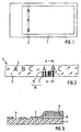
- a security document 1 such as a banknote, in which a security element 2 in the form of a so-called window security thread is embedded.
- the security thread 2 is virtually woven into the pulp during papermaking, so that it occurs at regular intervals directly to the document surface, which is indicated by the hatched box.
- the security element 2 shows in principle the external appearance of the security element 2.
- the viewer of the security element 2 sees only the opaque layer 3, which has recesses 4, the negative writing, in certain areas.
- the magnetic coding 20 is obscured by the opaque layer 3 and therefore can not be localized without additional aids. However, it must be arranged in a region of the element 2 in which there is no negative writing 4 so as not to impair the optical effect of the negative writing 4.
- the elevation in area 6 shows that the magnetic coding 20 is arranged parallel to the recesses 4 in this case. Both the coding 20 and the recesses occupy about half the thread width.
- the coding 20 is composed of magnetic regions 5 and non-magnetic regions 15 and can be arranged several times on the security element 2. Preferably, the coding 20 is repeated continuously along the element 2.
- the magnetic coding 20 and the opaque layer 3 with the recesses 4 are arranged on an at least translucent plastic material 7.
- a thread which is embedded in the document material it is usually a plastic film, which preferably has a thickness of about 10 to 20 microns.
- a security element that is applied to the document surface, however, it may also be useful to form the plastic material as a thin lacquer layer. Here it makes sense to prepare the layer structure on a separate sheet and then transfer it to the document. This may be particularly advantageous if the security element additionally has a diffraction structure in the form of a relief structure which has been embossed into the plastic material.
- the plastic material may also have other safety relevant features, such as e.g. a coloring with translucent colors and / or luminescent substances.
- the magnetic coding 20 is arranged. Shown here by a magnetic region 5.
- a further opaque layer 8 can be arranged under the coding 20 be.
- This layer 8 can be provided either in the form of a strip over the entire length of the security element 2 or only in the magnetic material-coated areas 5 of the coding 20.
- the opaque layer 8 is made of the same material as the opaque layer 3 or has at least the same hue as the opaque layer 3. However, it can also consist of a material that contrasts with the opaque layer 3 in color.
- the opaque layer 3 is arranged, which covers not only the coding 20 but also the remaining regions of the plastic layer 7 and is interrupted only in places in the form of the negative signs 4.
- This thread 2 can be made in a very simple and efficient way.
- the plastic material 7 is printed with the lower opaque layer 8.
- the magnetic layer 5 and at the same time in the region of the later characters 4 a soluble ink layer is applied in one printing operation or in two successive printing processes.
- the opaque layer 3, preferably aluminum, is vapor-deposited over the entire thread material.
- the soluble ink is dissolved in the region of the characters 4 with a suitable solvent and thus removed in these areas, the metal, so that the negative signs 4 arise.
- the opaque layer 3 is preferably used as a printing layer in which the characters 4 are omitted during the printing process.
- a metal pigment-containing printing ink is preferably used.
- FIG. 4 shows an alternative layer structure, as it results from a section along A - A in FIG. 2 according to the invention.
- the coding 20 or the magnetic material 5 and the opaque layer 3 with the negative marks 4 are arranged on different surfaces of the plastic material 7.
- the magnetic coding is covered on both sides of opaque layers 3 and 8 respectively.
- the opaque layer 8 may be dispensed with if magnetic iron material is used for the magnetic regions of the coding 20 or the magnetic regions 5 of the coding 20, which has a light intrinsic color in contrast to the normally used dark magnetic materials.
- the plastic material 7 is provided in a first step with a semi-transparent metal layer 9, which either by rastered application of an opaque metal layer or by vapor deposition of a very thin, continuous metal layer is produced.
- the magnetic coding 20 is applied to this layer, which is then covered with an opaque, preferably black printing ink 3 and at the same time the negative signs 4 are generated.
- a semitransparent metal layer 10 is again provided over the entire element layer structure in a last step. Due to the semitransparency of the layers 9 and 10, the recesses 4 remain visible in transmitted light as before.
- the coding 20 extends over the entire width of the thread. It is composed of areas 5, which are provided with magnetic material, and magnetic layer-free areas 15 together.
- the code 20 consists of equal bit cells that are either filled with magnetic material (eg, binary "1") or not (eg, binary "0").
- the magnetic layer-free regions 15 of the coding 20 are used in order to arrange the recesses 4 visible in the transmission. In this way Negativschrift 4 and magnetic coding 20 can be provided together on a thread, without affecting each other. The recesses 4 can therefore be arranged in the middle of the thread and produced in the usual size, as in the case of threads which have only one negative writing.
- the recesses 4 can be selected to be so large that they are easily recognizable by the eye, which is particularly advantageous for security threads with a width of 2 to 3 mm, which are embedded in the document material.
- the thread has the same appearance as a conventional negative writing security thread. None indicates from the outside that at the same time a magnetic coding is arranged on the thread.
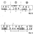
- the idea according to the invention of arranging the recesses 4 in the magnetic layer-free intermediate regions 15 of the coding 20 can also be used particularly advantageously in a coding which is composed of word and separating segments, as is known, for example, from EP 0 407 550 A1. Because one chooses for the bit sequence of the separation segments only binary "0", i. magnetic-layer-free bit cells, this results in a relatively large, magnetic layer-free space in which easily the recesses can be arranged.
- recesses 16 can also be provided in the magnetic-layer-free regions of the word segments. Increased protection against counterfeiting is achieved when the recesses 16 are executed as micro-characters, i. have a much smaller size than the recesses 4. Because the micro-characters can not be imitated or only with great effort.
- FIG. 11 A further embodiment variant is shown in FIG. 11.
- the code 20 and the negative writing 4 or the magnetic layer 5 with the intermediate recesses 4 are not arranged over the entire width of the thread.
- recesses 16 are provided, which, as already described, differ in size from the recesses 4.
- the basic idea of this embodiment is to provide an additional magnetic layer in addition to the magnetic coding and the negative writing, whereby an additional protection against counterfeiting is achieved.
- the magnetic regions 5 of the coding 20 become over another Magnetic layer 11 connected together.
- this magnetic layer 11 must not affect the readability of the coding 20. Since the sensors with which the magnetic coding is read usually require a strong signal, the magnetic material 5 of the coding 20 must have a certain minimum thickness. For a pure magnetic "continuity test" along the thread 2, however, a much smaller layer thickness would be sufficient. That is, the magnetic layer 11 must have a smaller thickness compared to the magnetic layer 5, so that a sensor to detect the coding 20 receives no signal from the magnetic layer 11.
- This magnetic pattern can also be produced in a simple manner by first printing the film 7 with a magnetic strip in the thickness of the magnetic layer 11 and subsequently applying in a second printing process in the regions 5 a magnetic layer whose layer thickness is precisely the difference between the layer thickness the magnetic layer 11 and the required for the coding 20 layer thickness corresponds.
- Fig. 8 shows another embodiment.
- the second magnetic layer 12 is also applied in the form of a coding identical to the Encoding is 20.
- this second coding is applied parallel to the first coding and the recesses 4 are arranged between them.
- the codings may in this case be arranged symmetrically or asymmetrically with respect to the recesses 4.
- the codes can also be provided in a different arrangement on the element, it should only be noted that the negative writing 4 is not obscured.
- the second magnetic layer 13 is likewise applied in the form of a coding.
- this is a negative representation of the first coding 20.
- the two codings are applied parallel and exactly to one another with a gap, so that a continuous magnetic signal results during a test along the thread.
- the security element in subregions here I, II, III, un tergliedert be. At least in the individual sections once the full coding 20 and a negative lettering 4. Both are arranged parallel to each other. In sub-area II, however, the arrangement of the negative writing 4 and the coding 20 changes relative to the arrangement in sub-area I. In the present case, it is a rotation through 180 °, but it would also be possible to arrange the sub-areas in other orientations to each other.
- the subregions could be identical in their internal structure and only the orientation of the subregions could vary, for example by being arranged at different angles to one another.
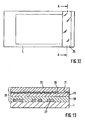
- FIGS. 12 and 13 show a further embodiment of the security document or security element according to the invention.
- FIG. 12 shows a top view of a security document 1, on the surface of which a security element 25 is arranged.
- This security element 25 has an optically variable structure, which causes a change in the color impression of the information displayed when changing the viewing angle and / or reveals another information.
- it is an embossed diffraction structure combined with a metal layer so that the information stored in the diffraction structure becomes visible to the viewer in reflection.
- FIG. 13 shows a section along A - A, which makes the layer structure of the security element 25 clear.
- the value document 1 is provided with a lacquer layer 27 which is applied in the form of a coding, for example a bar code.
- This lacquer layer contains magnetic pigments which can be detected by machine.
- a full-surface further lacquer layer 28 is arranged, which contains no magnetic pigments and serves primarily to compensate for the surface roughness of the document 1 and to ensure good adhesion to the following layers.
- an adhesive layer 29 which may for example consist of a paint or a hot melt adhesive. Adjoining this adhesive layer 29 is a metal layer 30 whose surface has a relief structure which represents the diffraction structure.
- This metal layer 30 contains recesses 31 in the form of characters, patterns or the like, which constitute additional visually visible information.
- a further lacquer layer 32 is arranged above the metal layer. This may consist of any material, such as UV-curable polymers or UV-radiation-initiated polymers or thermoplastic materials.
- the lacquer layer 32, the metal layer 30 and the adhesive layer 29 are advantageously prepared on a separate carrier layer and then connected after the application of the lacquer layers 27 and 28 with the value document material 1.
- the carrier material is subsequently removed from the lacquer layer 32.
- the magnetic layer 27 is usually printed by any printing method, it is very easy to apply the magnetic coding in the areas of the security element 25 in which there are no recesses 31.
- further additives can be integrated, such as color pigments, luminescent pigments or effect or luster pigments.
- the security elements according to the invention can be used advantageously not only on or in bank notes, but also on any other documents, such as e.g. Checks, identity cards or the like.
- a diffraction structure consisting of a lacquer layer, a metal layer and an adhesive layer
- other optically variable layers such as e.g. Interference layer constructions, printing inks with interference-layer pigments or liquid-crystal pigments, etc.
- optically variable layers such as, for example, certain interference layer pigments
- the magnetic code represented by layer 27 is still machine readable through these layers.
Abstract
Description
Die Erfindung betrifft ein Sicherheitselement für ein Sicherheitsdokument, wie eine Banknote, Ausweiskarte oder dergleichen, bestehend aus einem transluzenten Trägermaterial, das eine opake Schicht mit in Transmission erkennbaren Aussparungen in Form von Zeichen, Mustern oder dergleichen aufweist, sowie eine magnetische Schicht, die unter der opaken Schicht angeordnet ist.The invention relates to a security element for a security document, such as a banknote, identity card or the like, consisting of a translucent carrier material having an opaque layer with visible in transmission recesses in the form of characters, patterns or the like, and a magnetic layer which under the opaque layer is arranged.
Es ist seit langem bekannt, Sicherheitsdokumente mit Sicherheitsfäden aus Kunststoff zu versehen, welche eine magnetische Beschichtung aufweisen und damit als maschinenlesbares Sicherheitsmerkmal dienen (DE 16 96 245 A1, EP 0 310 707 A1).It has long been known to provide security documents with security threads made of plastic, which have a magnetic coating and thus serve as a machine-readable security feature (DE 16 96 245 A1, EP 0 310 707 A1).
Um die Fälschungssicherheit dieses bewährten Sicherheitsmerkmals weiter zu erhöhen, wurde auch bereits vorgeschlagen, die magnetische Beschichtung in diskontinuierlicher Form auf dem Trägermaterial vorzusehen. So beschreibt beispielsweise die EP 0 407 550 A1 ein Sicherheitsdokument mit einem eingelagerten Sicherheitsfaden, der mit einem Binärcode aus magnetischem Material versehen ist. Hierbei werden bestimmte Bitlängen definiert, welche über die gesamte Länge des Streifens konstant sind. Die Belegung einer Bitlänge mit magnetischem Material entspricht beispielsweise einer 1, während eine nicht mit magnetischem Material versehene Bitlänge einer 0 entspricht. Der aus der EP 0 407 550 A1 bekannte Binärcode zeichnet sich nun dadurch aus, daß er sich aus alternierend angeordneten Trennsegmenten und Wortsegmenten zusammensetzt, wobei der Wortabschnitt aus einer bestimmten Anzahl von Bitlängen besteht und die Folge der Binärwerte der Trennsegmente innerhalb dieser Wortlänge nicht vorkommen darf, um eine eindeutige Erkennung der Wortsegmente zu ermöglichen. Dieses Sicherheitselement besitzt allerdings den Nachteil, daß es keine Möglichkeit für eine schnelle visuelle Überprüfung bietet, wie sie in vielen Situationen des täglichen Lebens notwendig ist.In order to further increase the security against forgery of this proven security feature, it has also been proposed to provide the magnetic coating in discontinuous form on the carrier material. For example, EP 0 407 550 A1 describes a security document with a stored security thread provided with a binary code made of magnetic material. Here, certain bit lengths are defined, which are constant over the entire length of the strip. The assignment of a bit length with magnetic material corresponds for example to a 1, while a bit length not provided with magnetic material corresponds to a zero. The binary code known from EP 0 407 550 A1 is distinguished by the fact that it consists of alternately arranged separating segments and word segments, wherein the word segment consists of a certain number of bit lengths and the sequence of binary values of the separating segments must not occur within this word length to allow unambiguous recognition of the word segments. However, this security element has the disadvantage that there is no way for provides a quick visual check, as it is necessary in many situations of daily life.
Es wurde daher ebenfalls vorgeschlagen, maschinell prüfbare Sicherheitsmerkmale mit visuellen Merkmalen zu kombinieren. Aus der EP 0 516 790 A1 ist bereits ein Sicherheitsdokument mit einem derartigen Sicherheitselement bekannt. Der hier beschriebene Sicherheitsfaden besteht aus einer transparenten Kunststoffträgerschicht mit einer metallischen Beschichtung, in welcher Aussparungen in Form von Zeichen oder Mustern, der sogenannten "Negativschrift", vorgesehen sind. Diese Aussparungen und die metallische Umgebung sind, sofern der Faden in der Papiermasse vorliegt, bei Betrachtung im Auflicht kaum sichtbar. Bei Betrachtung im Durchlicht allerdings heben sich die lichtdurchlässigen Aussparungen stark kontrastierend von ihrer opaken Umgebung ab und sind damit gut erkennbar. Zugleich weist das Sicherheitselement eine magnetische Beschichtung auf, die z.B. unterhalb der Metallschicht in den Randbereichen des Fadens und symmetrisch zu den Aussparungen entlang der Laufrichtung des Elements im Dokument vorgesehen ist.It has therefore also been proposed to combine machine-testable security features with visual features. A security document with such a security element is already known from EP 0 516 790 A1. The security thread described here consists of a transparent plastic carrier layer with a metallic coating, in which recesses in the form of characters or patterns, the so-called "negative writing" are provided. These recesses and the metallic environment, if the thread is present in the pulp, hardly visible when viewed in incident light. When viewed in transmitted light, however, the translucent recesses contrast strongly from their opaque environment and are thus easily recognizable. At the same time, the security element has a magnetic coating, e.g. is provided below the metal layer in the edge regions of the thread and symmetrical to the recesses along the running direction of the element in the document.
Der Erfindung liegt ausgehend von diesem Stand der Technik die Aufgabe zugrunde, ein Sicherheitselement vorzuschlagen, das einen erhöhten Fälschungsschutz bietet und gleichzeitig einfach herstellbar ist.The invention is based on this prior art, the object to propose a security element that offers increased protection against counterfeiting and at the same time is easy to produce.
Die Lösung dieser Aufgabe ergibt sich aus den unabhängigen Ansprüchen. Weiterbildungen sind Gegenstand der Unteransprüche.The solution to this problem arises from the independent claims. Further developments are the subject of the dependent claims.
Die Erfindung geht von der Idee aus, die Vorteile der visuell prüfbaren Negativschrift und der maschinell lesbaren magnetischen Codierung zu kombinieren und über die besondere gegenseitige Zuordnung auf dem Sicherheitselement einen gegenüber den einzelnen Sicherheitsmerkmalen erhöhten Fälschungsschutz zu gewährleisten.The invention is based on the idea of combining the advantages of the visually inspectable negative writing and the machine-readable magnetic coding and of the special mutual assignment on the security element to ensure an increased counterfeit protection compared to the individual security features.
Das erfindungsgemäße Sicherheitselement besteht daher gemäß einer ersten Ausführungsform aus einer zumindest transluzenten Kunststoffschicht, die eine opake Schicht mit Aussparungen sowie eine magnetische Codierung aufweist, wobei die Aussparungen in den magnetschichtfreien Bereichen des Elements angeordnet sind. Die besondere geometrische Anordnung der Aussparungen und der magnetischen Bereiche kann beispielsweise in einer Ineinanderschachtelung von Codierung und Aussparungen bestehen, d.h. die magnetschichtfreien Anteile der Codierung werden genutzt, um in diesem Bereich die visuell prüfbaren Negativschriftzeichen anzuordnen. Zusätzlich ist es allerdings auch möglich, ein weiteres maschinenlesbares Merkmal, wie z.B. eine weitere magnetische Schicht auf dem Sicherheitselement vorzusehen, das selbstverständlich die Überprüfbarkeit der anderen Merkmale nicht beeinträchtigen darf.The security element according to the invention therefore consists according to a first embodiment of an at least translucent plastic layer which has an opaque layer with recesses and a magnetic coding, wherein the recesses are arranged in the magnetic layer-free regions of the element. The particular geometric arrangement of the recesses and the magnetic regions may consist, for example, in a nesting of coding and recesses, i. the magnetic-layer-free portions of the coding are used to arrange the visually verifiable negative characters in this area. In addition, however, it is also possible to use another machine-readable feature, e.g. to provide a further magnetic layer on the security element, which of course must not affect the verifiability of the other features.
Gemäß einer bevorzugten Ausführungsform weist das Sicherheitselement die Form eines Fadens oder Streifens auf, das zumindest teilweise in ein Dokumentenmaterial, wie z.B. Banknotenpapier, eingebettet wird, oder auch auf der Oberfläche angeordnet sein kann.According to a preferred embodiment, the security element is in the form of a thread or strip which is at least partially embedded in a document material such as e.g. Banknote paper, embedded, or may be arranged on the surface.
Wenn das Sicherheitselement auf der Oberfläche des Dokumentenmaterials angeordnet wird, ist es nicht unbedingt notwendig, alle für die Echtheitserkennung notwendigen Schichten auf einem separaten Träger vorzubereiten. Weist das Sicherheitselement eine optisch wirksame Schicht, wie z.B. eine Beugungsstruktur oder Interferenzschichtelemente auf, ist es notwendig, die Oberfläche des Dokumentenmaterials im Bereich des Sicherheitselements zu glätten, da Oberflächenrauhigkeiten den optischen Effekt und die Brillanz des Elements beeinträchtigen. Dies geschieht häufig durch Aufbringen einer Untergrundschicht, beispielsweise einer Lackschicht. In diese Schicht kann nun zusätzlich das magnetische Material eingebracht werden.When the security element is placed on the surface of the document material, it is not absolutely necessary to prepare all the layers necessary for authentication on a separate support. If the security element has an optically active layer, such as a diffraction structure or interference layer elements, it is necessary to smooth the surface of the document material in the area of the security element, since surface roughnesses have the optical effect and the brilliance of the element. This is often done by applying a background layer, such as a lacquer layer. In this layer can now be additionally introduced the magnetic material.
Gemäß einer weiteren Ausführungsform der Erfindung kann diese Untergrundschicht in zwei Durchgängen aufgebracht werden. Der ersten aufzubringenden Schicht wird ein Magnetmaterial zugesetzt und diese Schicht anschließend diskontinuierlich, z.B. in Form eines Barcodes aufgebracht. Die zweite Schicht wird vollflächig über der ersten Schicht angeordnet und ist so zusammengesetzt, daß eine optimale Haftung zwischen Dokumentenmaterial und weiteren aufzubringenden Kennzeichnungsschichten, wie z.B. einem Hologramm erzeugt wird. Auch hier ist das Sicherheitselement vorzugsweise in Form eines Streifens ausgeführt.According to a further embodiment of the invention, this background layer can be applied in two passes. A magnetic material is added to the first layer to be applied, and this layer is then discontinuously, e.g. applied in the form of a barcode. The second layer is placed over the entire surface over the first layer and is assembled so as to provide optimum adhesion between document material and other marking layers to be applied, such as e.g. a hologram is generated. Again, the security element is preferably designed in the form of a strip.
Die folgenden Beispiele werden daher auch anhand dieser bevorzugten Form beschrieben. Es ist allerdings im Rahmen der Erfindung ebenso möglich, dem Sicherheitselement jede beliebige andere Umrißform zu geben.The following examples are therefore also described in terms of this preferred form. However, it is within the scope of the invention also possible to give the security element any other outline shape.
Die besonderen Ausführungsformen der Erfindung sowie ihre Vorteile werden anhand der Figuren näher erläutert.The particular embodiments of the invention and their advantages will be explained in more detail with reference to FIGS.
Es zeigen:
- Fig. 1
- ein Sicherheitsdokument mit einem erfindungsgemäßen Sicherheitselement,
- Fig. 2
- ein erfindungsgemäßes Sicherheitselement in Aufsicht,
- Fig. 3 bis 5
- Varianten des Schichtaufbaus des Sicherheitselementes bei einem Schnitt entlang A - A,
- Fig. 6 bis 11
- schematische Darstellungen der relativen Anordnung der Negativschrift und der Codierung zueinander in Aufsicht,
- Fig. 12
- ein Sicherheitsdokument mit einer Variante des erfindungsgemäßen Sicherheitselements,
- Fig. 13
- einen Schnitt entlang A - A durch das Sicherheitsdokument gemäß Fig. 12.
- Fig. 1
- a security document with a security element according to the invention,
- Fig. 2
- an inventive security element in supervision,
- Fig. 3 to 5
- Variants of the layer structure of the security element at a section along A - A,
- Fig. 6 to 11
- schematic representations of the relative arrangement of the negative writing and the coding to each other in supervision,
- Fig. 12
- a security document with a variant of the security element according to the invention,
- Fig. 13
- a section along A - A through the security document of FIG. 12th
Fig. 1 zeigt ein erfindungsgemäßes Sicherheitsdokument 1, wie eine Banknote, in welches ein Sicherheitselement 2 in Form eines sogenannten Fenster-Sicherheitsfadens eingebettet ist. Hierbei wird der Sicherheitsfaden 2 während der Papierherstellung in die Papiermasse quasi eingewebt, so daß er in regelmäßigen Abständen direkt an die Dokumentenoberfläche tritt, was durch die schraffierten Kästchen angedeutet wird. Alternativ ist es jedoch auch möglich, den Faden vollständig in das Papier einzubetten oder ihn so mit dem Dokumentenmaterial zu verbinden, daß er vollflächig an der Oberfläche zu sehen ist1 shows a
Fig. 2 zeigt prinzipiell das äußere Erscheinungsbild des Sicherheitselements 2. Der Betrachter des Sicherheitselements 2 sieht lediglich die opake Schicht 3, die in bestimmten Bereichen Aussparungen 4, die Negativschrift, aufweist. Die magnetische Codierung 20 wird von der opaken Schicht 3 verdeckt und ist daher nicht ohne zusätzliche Hilfsmittel zu lokalisieren. Sie muß allerdings in einem Bereich des Elements 2 angeordnet sein, in welchem sich keine Negativschrift 4 befindet, um den optischen Effekt der Negativschrift 4 nicht zu beeinträchtigen.2 shows in principle the external appearance of the
Der Aufriß im Bereich 6 zeigt, daß die magnetische Codierung 20 in diesem Fall parallel zu den Aussparungen 4 angeordnet ist. Sowohl die Codierung 20 als auch die Aussparungen nehmen in etwa die halbe Fadenbreite ein.The elevation in area 6 shows that the
Die Codierung 20 setzt sich aus magnetischen Bereichen 5 und unmagnetischen Bereichen 15 zusammen und kann mehrmals auf dem Sicherheitselement 2 angeordnet sein. Vorzugsweise wiederholt sich die Codierung 20 fortlaufend entlang des Elements 2.The
Ein Schnitt entlang A - A durch diesen Faden ist in Fig. 3 dargestellt. Die magnetische Codierung 20 und die opake Schicht 3 mit den Aussparungen 4 sind auf einem zumindest transluzenten Kunststoffmaterial 7 angeordnet. Im Falle eines Fadens, der in das Dokumentenmaterial eingebettet ist, handelt es sich üblicherweise um eine Kunststoffolie, die vorzugsweise eine Dicke von ca. 10 bis 20 µm aufweist. Im Falle eines Sicherheitselements, das auf die Dokumentenoberfläche aufgebracht wird, kann es allerdings auch sinnvoll sein, das Kunststoffmaterial als dünne Lackschicht auszubilden. Hier bietet es sich an, den Schichtaufbau auf einer separaten Folie vorzubereiten und anschließend auf das Dokument zu übertragen. Dies kann insbesondere von Vorteil sein, wenn das Sicherheitselement zusätzlich eine Beugungsstruktur in Form einer Reliefstruktur aufweist, die in das Kunststoffmaterial eingeprägt wurde. Das Kunststoffmaterial kann auch andere sicherheitstechnisch relevante Merkmale aufweisen, wie z.B. eine Einfärbung mit lasierenden Farben und/oder Lumineszenzstoffen.A section along A - A through this thread is shown in FIG. The
Im Randbereich des Kunststoffmaterials 7 ist die magnetische Codierung 20 angeordnet. Hier durch einen magnetischen Bereich 5 dargestellt. Um das magnetische Material 5 von beiden Seiten des Fadens 2 unsichtbar zu machen, kann unter der Codierung 20 eine weitere opake Schicht 8 angeordnet sein. Diese Schicht 8 kann entweder in Form eines Streifens über die gesamte Länge des Sicherheitselements 2 oder nur in den mit Magnetmaterial beschichteten Bereichen 5 der Codierung 20 vorgesehen sein. Vorzugsweise besteht die opake Schicht 8 aus dem gleichen Material wie die opake Schicht 3 oder weist zumindest den gleichen Farbton wie die opake Schicht 3 auf. Sie kann jedoch auch aus einem Material bestehen, das zur opaken Schicht 3 farblich kontrastiert.In the edge region of the plastic material 7, the
Über der Codierung 20 ist die opake Schicht 3 angeordnet, die nicht nur die Codierung 20 sondern auch die übrigen Bereiche der Kunststoffschicht 7 abdeckt und lediglich stellenweise in Form der Negativzeichen 4 unterbrochen ist.Above the
Dieser Faden 2 kann auf sehr einfache und rationelle Weise hergestellt werden. In einem ersten Schritt wird das Kunststoffmaterial 7 mit der unteren opaken Schicht 8 bedruckt. Anschließend wird die Magnetschicht 5 und gleichzeitig im Bereich der späteren Zeichen 4 eine lösliche Farbschicht in einem Druckvorgang oder in zwei aufeinanderfolgenden Druckvorgängen aufgebracht. In einem weiteren Schritt wird die opake Schicht 3, vorzugsweise Aluminium, über das gesamte Fadenmaterial aufgedampft. In einem letzten Schritt wird die lösliche Druckfarbe im Bereich der Zeichen 4 mit einem geeigneten Lösungsmittel gelöst und damit in diesen Bereichen das Metall entfernt, so daß die Negativzeichen 4 entstehen.This
Alternativ ist es auch möglich, die opake Schicht 3 als Druckschicht auszuführen, bei welcher während des Druckvorgangs die Zeichen 4 ausgespart werden. Hierfür wird vorzugsweise eine metallpigmenthaltige Druckfarbe verwendet.Alternatively, it is also possible to carry out the
Fig. 4 zeigt einen alternativen Schichtaufbau, wie er sich bei einem Schnitt entlang A - A in Fig. 2 gemäß der Erfindung ergibt. Hier werden die Codierung 20 bzw. das Magnetmaterial 5 und die opake Schicht 3 mit den Negativzeichen 4 auf unterschiedlichen Oberflächen des Kunststoffmaterials 7 angeordnet. Auch hier wird die Magnetcodierung beidseitig von opaken Schichten 3 bzw. 8 abgedeckt. Auf die opake Schicht 8 kann verzichtet werden, wenn für die magnetischen Bereiche der Codierung 20 bzw. die magnetischen Bereiche 5 der Codierung 20 magnetisches Eisenmaterial verwendet wird, welches im Gegensatz zu den üblicherweise verwendeten dunklen Magnetmaterialien eine helle Eigenfarbe aufweist.FIG. 4 shows an alternative layer structure, as it results from a section along A - A in FIG. 2 according to the invention. Here, the
Fig. 5 zeigt eine weitere Variante des Schichtaufbaus eines Sicherheitselements gemäß Fig. 2. Hier wird das Kunststoffmaterial 7 in einem ersten Schritt mit einer semitransparenten Metallschicht 9 versehen, welche entweder durch gerastertes Aufbringen einer opaken Metallschicht oder aber durch Aufdampfen einer sehr dünnen, durchgehenden Metallschicht erzeugt wird. Auf diese Schicht wird die Magnetcodierung 20 aufgebracht, welche anschließend mit einer opaken, vorzugsweise schwarzen Druckfarbe 3 abgedeckt und gleichzeitig die Negativzeichen 4 erzeugt werden. Um diesem Faden ein helleres Erscheinungsbild zu geben, wird in einem letzten Schritt nochmals eine semitransparente Metallschicht 10 über dem gesamten Elementschichtaufbau vorgesehen. Aufgrund der Semitransparenz der Schichten 9 und 10 bleiben die Aussparungen 4 im Durchlicht nach wie vor erkennbar.Here, the plastic material 7 is provided in a first step with a semi-transparent metal layer 9, which either by rastered application of an opaque metal layer or by vapor deposition of a very thin, continuous metal layer is produced. The
Vor dem Hintergrund dieser prinzipiellen Möglichkeiten des Fadenaufbaus ist es nun auch möglich, die Aussparungen 4 und die Magnetcodierung 20 in anderen geometrischen Konstellationen anzuordnen oder sie mit einem weiteren visuell und/ oder maschinell lesbaren Merkmal zu kombinieren, um den Fälschungsschutz weiter zu erhöhen. Derartige Varianten zeigen schematisch die Fig. 6 bis 11 in Aufsicht Zur besseren Anschaulichkeit werden hier lediglich die Codierung 20 sowie die Aussparungen 4 in ihrer relativen Lage zueinander auf dem Faden gezeigt. Die opake Schicht 3 sowie weitere möglicherweise vorhandene Schichten werden nicht gezeigt.Against the background of these basic possibilities of yarn structure, it is now also possible to arrange the
Gemäß Fig. 6 erstreckt sich die Codierung 20 über die gesamte Breite des Fadens. Sie setzt sich aus Bereichen 5, die mit magnetischem Material versehen sind, und magnetschichtfreien Bereichen 15 zusammen. In einer speziellen Ausführungsform besteht der Code 20 aus gleichgroßen Bitzellen, die entweder mit magnetischem Material gefüllt (z.B. binäre "1") werden oder nicht (z.B. binäre "0"). Gemäß der Erfindung werden die magnetschichtfreien Bereiche 15 der Codierung 20 genutzt, um hier die in Transmission erkennbaren Aussparungen 4 anzuordnen. Auf diese Weise können Negativschrift 4 und Magnetcodierung 20 gemeinsam auf einem Faden vorgesehen werden, ohne sich gegenseitig zu beeinträchtigen. Die Aussparungen 4 können daher wie bei Fäden, die lediglich eine Negativschrift aufweisen, in der Fadenmitte angeordnet und in der üblichen Größe erzeugt werden. Dies hat zum einen den Vorteil, daß die Aussparungen 4 so groß gewählt werden können, daß sie vom Auge gut erkennbar sind, was insbesondere bei Sicherheitsfäden mit einer Breite von 2 bis 3 mm, die in das Dokumentenmaterial eingebettet werden, von Vorteil ist. Zudem weist der Faden das gleiche äußere Erscheinungsbild auf wie ein üblicher Negativschrift-Sicherheitsfaden. Nichts läßt von außen erkennen, daß gleichzeitig eine Magnetcodierung auf dem Faden angeordnet ist.According to FIG. 6, the
Die erfindungsgemäße Idee, die Aussparungen 4 in den magnetschichtfreien Zwischenbereichen 15 der Codierung 20 anzuordnen, läßt sich auch besonders vorteilhaft bei einer Codierung einsetzen, die sich aus Wort- und Trennsegmenten zusammensetzt, wie sie beispielsweise aus der EP 0 407 550 A1 bekannt ist. Denn wählt man für die Bitfolge der Trennsegmente lediglich binäre "0", d.h. magnetschichtfreie Bitzellen, so entsteht ein relativ großer, magnetschichtfreier Zwischenraum, in welchem problemlos die Aussparungen angeordnet werden können.The idea according to the invention of arranging the
Zusätzlich können selbstverständlich auch in den magnetschichtfreien Bereichen der Wortsegmente Aussparungen 16 vorgesehen werden. Ein erhöhter Fälschungsschutz wird dabei erzielt, wenn die Aussparungen 16 als Mikroschriftzeichen ausgeführt werden, d.h. eine wesentlich geringere Größe aufweisen als die Aussparungen 4. Denn die Mikroschriftzeichen lassen sich nicht oder nur mit hohem Aufwand imitieren.In addition, of course, recesses 16 can also be provided in the magnetic-layer-free regions of the word segments. Increased protection against counterfeiting is achieved when the
Eine weitere Ausgestaltungsvariante zeigt Fig. 11. Hier wird der Code 20 und die Negativschrift 4 bzw. die Magnetschicht 5 mit den dazwischenliegenden Aussparungen 4 nicht über die gesamte Breite des Fadens angeordnet. Im verbleibenden Teil des Sicherheitselements werden ebenfalls Aussparungen 16 vorgesehen, die sich, wie bereits beschrieben, in der Größe von den Aussparungen 4 unterscheiden.A further embodiment variant is shown in FIG. 11. Here, the
Die grundlegende Idee dieser Ausführungsform liegt darin, neben der Magnetcodierung und der Negativschrift eine weitere Magnetschicht vorzusehen, wodurch ein zusätzlicher Fälschungsschutz erzielt wird. Gemäß Fig. 7 werden die magnetischen Bereiche 5 der Codierung 20 über eine weitere Magnetschicht 11 miteinander verbunden. Diese Magnetschicht 11 darf selbstverständlich die Lesbarkeit der Codierung 20 nicht beeinträchtigen. Da die Sensoren, mit welchen die Magnetcodierung gelesen wird, meist ein starkes Signal benötigen, muß das Magnetmaterial 5 der Codierung 20 eine bestimmte Mindestdicke aufweisen. Für eine reine magnetische "Durchgangsprüfung" entlang des Fadens 2 wäre jedoch eine wesentlich geringere Schichtdicke ausreichend. Das bedeutet, die Magnetschicht 11 muß eine im Vergleich zur Magnetschicht 5 geringere Dicke aufweisen, so daß ein Sensor, der die Codierung 20 erfassen soll, kein Signal von der Magnetschicht 11 erhält.The basic idea of this embodiment is to provide an additional magnetic layer in addition to the magnetic coding and the negative writing, whereby an additional protection against counterfeiting is achieved. According to FIG. 7, the
Dieses magnetische Muster läßt sich auch auf einfache Weise herstellen, indem die Folie 7 zuerst mit einem magnetischen Streifen in der Dicke der Magnetschicht 11 bedruckt und anschließend in einem zweiten Druckvorgang in den Bereichen 5 eine Magnetschicht aufgebracht wird, deren Schichtstärke gerade der Differenz zwischen der Schichtstärke der Magnetschicht 11 und der für die Codierung 20 benötigten Schichtstärke entspricht.This magnetic pattern can also be produced in a simple manner by first printing the film 7 with a magnetic strip in the thickness of the
Auf diese Weise kann entweder allein das Vorhandensein von magnetischem Material über die gesamte Fadenlänge oder die magnetische Codierung oder auch beides überprüft werden.In this way, either only the presence of magnetic material over the entire length of the thread or the magnetic coding or both can be checked.
Denkbar wäre auch, für die Magnetschicht 11 ein anderes magnetisches Material zu wählen und neben der Codierung 20 das Vorhandensein der spezifischen physikalischen Eigenschaften dieser zweiten Magnetschicht 11 zu prüfen.It would also be conceivable to choose a different magnetic material for the
Fig. 8 zeigt eine weitere Ausführungsform. Hier wird die zweite Magnetschicht 12 ebenfalls in Form einer Codierung aufgebracht, die identisch zur Codierung 20 ist. Im vorliegenden Beispiel wird diese zweite Codierung parallel zur ersten Codierung aufgebracht und zwischen diesen die Aussparungen 4 angeordnet. Die Codierungen können hierbei symmetrisch oder asymmetrisch zu den Aussparungen 4 angeordnet sein. Die Codierungen können jedoch auch in einer anderen Anordnung auf dem Element vorgesehen werden, zu beachten ist lediglich, daß die Negativschrift 4 nicht verdeckt wird.Fig. 8 shows another embodiment. Here, the second
Aufgrund der doppelten Codierung ist es möglich, eine Koinzidenzprüfung durchzuführen, bei welcher die Codierungen unabhängig voneinander gelesen und anschließend auf Übereinstimmung geprüft werden.Due to the double encoding, it is possible to perform a coincidence test in which the codings are read independently and then checked for consistency.
Gemäß Fig. 9 ist die zweite Magnetschicht 13 ebenfalls in Form einer Codierung aufgebracht. Allerdings handelt es sich hierbei um eine Negativdarstellung der ersten Codierung 20. Die beiden Codierungen werden parallel und exakt auf Lücke zueinander aufgebracht, so daß sich bei einer Prüfung entlang des Fadens ein kontinuierliches Magnetsignal ergibt.According to FIG. 9, the second
Selbstverständlich ist es auch im Falle der hier beschriebenen Ausführungsvarianten möglich, zwischen den magnetischen Bereichen 5,12,13 Aussparungen in Form von Zeichen beliebiger Größe vorzusehen. Ebenso ist es selbstverständlich möglich, die hier im Beispiel 2 beschriebenen Varianten bei den übrigen Ausführungsbeispielen, beispielsweise gemäß Fig. 6 oder 10 einzusetzen.Of course, it is also possible in the case of the embodiment variants described here to provide recesses in the form of characters of any size between the
Gemäß Fig. 10 kann das Sicherheitselement in Teilbereiche, hier I, II, III, un tergliedert werden. In den einzelnen Teilbereichen befindet sich zumindest einmal die vollständige Codierung 20 und ein Negativschriftzug 4. Beide sind parallel zueinander angeordnet. In Teilbereich II ändert sich jedoch die Anordnung der Negativschrift 4 und der Codierung 20 relativ zur Anordnung in Teilbereich I. Im vorliegenden Fall handelt es sich um eine Drehung um 180°, Es wäre jedoch auch möglich, die Teilbereiche in anderen Orientierungen zueinander anzuordnen. Bei breiteren Sicherheitselementen könnten beispielsweise die Teilbereiche in ihrern inneren Aufbau identisch sein und lediglich die Orientierung der Teilbereiche zueinander variieren, indem sie beispielsweise in unterschiedlichen Winkeln zueinander angeordnet werden.10, the security element in subregions, here I, II, III, un tergliedert be. At least in the individual sections once the
Je häufiger die Wechsel und je komplizierter die Anordnungen desto schwieriger wird es für potenzielle Fälscher, den Faden zu imitieren.The more frequent the changes and the more complicated the arrangements, the more difficult it becomes for potential counterfeiters to imitate the thread.
Die Fig. 12 und 13 zeigen eine weitere Ausführungsform des erfindungsgemäßen Sicherheitsdokuments bzw, Sicherheitselements. In Fig. 12 ist ein Sicherheitsdokument 1 in Aufsicht dargestellt, auf dessen Oberfläche ein Sicherheitselement 25 angeordnet ist. Dieses Sicherheitselement 25 weist eine optisch variable Struktur auf, die bei Änderung des Betrachtungswinkels eine Änderung des farblichen Eindrucks der dargestellten Information hervorruft und/oder eine andere Information erkennen läßt. Im gezeigten Beispiel handelt es sich um eine geprägte Beugungsstruktur, die mit einer Metallschicht kombiniert ist, so daß die in der Beugungsstruktur gespeicherte Information in Reflexion für den Betrachter erkennbar wird.FIGS. 12 and 13 show a further embodiment of the security document or security element according to the invention. FIG. 12 shows a top view of a
Fig. 13 zeigt einen Schnitt entlang A - A, der den Schichtaufbau des Sicherheitselements 25 deutlich macht. Das Wertdokument 1 ist mit einer Lackschicht 27 versehen, welche in Form einer Codierung, beispielsweise eines Barcodes aufgebracht ist Diese Lackschicht enthält magnetische Pigmente, die maschinell nachgewiesen werden können. Über dieser magnetischen Codierung ist eine vollflächige weitere Lackschicht 28 angeordnet, die keinerlei magnetische Pigmente enthält und in erster Linie dazu dient, die Oberflächenrauhigkeiten des Dokuments 1 auszugleichen und eine gute Haftung zu den folgenden Schichten zu gewährleisten. Auf dieser Lackschicht 28 befindet sich eine Klebstoffschicht 29, welche z.B. aus einem Lack oder einem Heißschmelzkleber bestehen kann. An diese Klebstoffschicht 29 schließt sich eine Metallschicht 30 an, deren Oberfläche eine Reliefstruktur aufweist, die die Beugungsstruktur darstellt. Diese Metallschicht 30 enthält Aussparungen 31 in Form von Zeichen, Mustern oder dergleichen, die eine zusätzliche visuell sichtbare Information darstellen. Über der Metallschicht ist schließlich eine weitere Lackschicht 32 angeordnet. Diese kann aus einem beliebigen Material bestehen, wie z.B. UV-härtbaren Polymeren oder durch UV-Strahlung initiierbaren Polymeren oder thermoplastischen Materialien.FIG. 13 shows a section along A - A, which makes the layer structure of the
Die Lackschicht 32, die Metallschicht 30 sowie die Klebstoffschicht 29 werden vorteilhafterweise auf einer separaten Trägerschicht vorbereitet und anschließend nach dem Aufbringen der Lackschichten 27 und 28 mit dem Wertdokumentenmaterial 1 verbunden. Das Trägermaterial wird anschließend von der Lackschicht 32 abgezogen.The
Da die magnetische Schicht 27 üblicherweise mit einem beliebigen Druckverfahren aufgedruckt wird, ist es sehr einfach möglich, die Magnetcodierung in den Bereichen des Sicherheitselements 25 aufzubringen, in denen sich keine Aussparungen 31 befinden. In die zweite Lackschicht 28 können weitere Zusätze integriert werden, wie beispielsweise Farbpigmente, lumineszierende Pigmente oder Effekt- bzw. Glanzpigmente.Since the
Die erfindungsgemäßen Sicherheitselemente können nicht nur auf oder in Banknoten vorteilhaft eingesetzt werden, sondern auch auf beliebigen anderen Dokumenten, wie z.B. Schecks, Ausweiskarten oder dergleichen.The security elements according to the invention can be used advantageously not only on or in bank notes, but also on any other documents, such as e.g. Checks, identity cards or the like.
Statt einer Beugungsstruktur, bestehend aus einer Lackschicht, einer Metallschicht und einer Klebstoffschicht, ist es auch möglich, andere optisch variable Schichten zu verwenden, wie z.B. Interferenzschichtaufbauten, Druckfarben mit Interferenzschichtpigmenten oder Flüssigkristallpigmenten etc.Instead of a diffraction structure consisting of a lacquer layer, a metal layer and an adhesive layer, it is also possible to use other optically variable layers, such as e.g. Interference layer constructions, printing inks with interference-layer pigments or liquid-crystal pigments, etc.
Bei der Verwendung von transluzenten, optisch variablen Schichten, wie beispielsweise bestimmten Interferenzschichtpigmenten, kann es sinnvoll sein, die Lackschicht 28 schwarz einzufärben, da dadurch die Brillanz der optisch variablen Schicht unterstützt werden kann. Der magnetische Code, der durch die Schicht 27 dargestellt wird, ist hierbei nach wie vor durch diese Schichten hindurch maschinell lesbar.When using translucent, optically variable layers, such as, for example, certain interference layer pigments, it may be useful to color the
Claims (34)
Priority Applications (2)
| Application Number | Priority Date | Filing Date | Title |
|---|---|---|---|
| EP10011495.8A EP2273456B1 (en) | 1996-12-06 | 1997-12-05 | Security element |
| EP10011494.1A EP2273455B1 (en) | 1996-12-06 | 1997-12-05 | Security element |
Applications Claiming Priority (2)
| Application Number | Priority Date | Filing Date | Title |
|---|---|---|---|
| DE19650759A DE19650759A1 (en) | 1996-12-06 | 1996-12-06 | Security element |
| EP97952891A EP0961996B9 (en) | 1996-12-06 | 1997-12-05 | Security device |
Related Parent Applications (2)
| Application Number | Title | Priority Date | Filing Date |
|---|---|---|---|
| EP97952891A Division EP0961996B9 (en) | 1996-12-06 | 1997-12-05 | Security device |
| EP97952891.6 Division | 1998-06-11 |
Related Child Applications (4)
| Application Number | Title | Priority Date | Filing Date |
|---|---|---|---|
| EP10011495.8A Division EP2273456B1 (en) | 1996-12-06 | 1997-12-05 | Security element |
| EP10011494.1A Division EP2273455B1 (en) | 1996-12-06 | 1997-12-05 | Security element |
| EP10011495.8 Division-Into | 2010-09-29 | ||
| EP10011494.1 Division-Into | 2010-09-29 |
Publications (3)
| Publication Number | Publication Date |
|---|---|
| EP1630751A2 true EP1630751A2 (en) | 2006-03-01 |
| EP1630751A3 EP1630751A3 (en) | 2007-01-03 |
| EP1630751B1 EP1630751B1 (en) | 2012-02-15 |
Family
ID=7813904
Family Applications (4)
| Application Number | Title | Priority Date | Filing Date |
|---|---|---|---|
| EP97952891A Expired - Lifetime EP0961996B9 (en) | 1996-12-06 | 1997-12-05 | Security device |
| EP05019772A Revoked EP1630751B1 (en) | 1996-12-06 | 1997-12-05 | Security element |
| EP10011495.8A Expired - Lifetime EP2273456B1 (en) | 1996-12-06 | 1997-12-05 | Security element |
| EP10011494.1A Expired - Lifetime EP2273455B1 (en) | 1996-12-06 | 1997-12-05 | Security element |
Family Applications Before (1)
| Application Number | Title | Priority Date | Filing Date |
|---|---|---|---|
| EP97952891A Expired - Lifetime EP0961996B9 (en) | 1996-12-06 | 1997-12-05 | Security device |
Family Applications After (2)
| Application Number | Title | Priority Date | Filing Date |
|---|---|---|---|
| EP10011495.8A Expired - Lifetime EP2273456B1 (en) | 1996-12-06 | 1997-12-05 | Security element |
| EP10011494.1A Expired - Lifetime EP2273455B1 (en) | 1996-12-06 | 1997-12-05 | Security element |
Country Status (9)
| Country | Link |
|---|---|
| US (1) | US6343745B1 (en) |
| EP (4) | EP0961996B9 (en) |
| AT (2) | ATE355573T1 (en) |
| AU (1) | AU5660098A (en) |
| DE (2) | DE19650759A1 (en) |
| PL (1) | PL188250B1 (en) |
| RU (1) | RU2196357C2 (en) |
| UA (1) | UA47510C2 (en) |
| WO (1) | WO1998025236A1 (en) |
Cited By (2)
| Publication number | Priority date | Publication date | Assignee | Title |
|---|---|---|---|---|
| DE102006040874A1 (en) * | 2006-08-31 | 2008-03-13 | Eastman Kodak Co. | Document characterizing method for electro graphic printing machine, involves providing document with bar code, and pigmenting region of bar code with color material for visualizing stripes, where stripes of bar code are transparent |
| WO2008061707A1 (en) * | 2006-11-22 | 2008-05-29 | Giesecke & Devrient Gmbh | Security element for documents of value |
Families Citing this family (57)
| Publication number | Priority date | Publication date | Assignee | Title |
|---|---|---|---|---|
| DE19548528A1 (en) * | 1995-12-22 | 1997-06-26 | Giesecke & Devrient Gmbh | Security document with a security element and method for its production |
| DE19907697A1 (en) * | 1999-02-23 | 2000-08-24 | Giesecke & Devrient Gmbh | Security element with optically variable material for documents of value additionally comprises at least one machine readable distinguishing material which does not impair the effect of the optically variable material |
| US7667895B2 (en) * | 1999-07-08 | 2010-02-23 | Jds Uniphase Corporation | Patterned structures with optically variable effects |
| US11768321B2 (en) | 2000-01-21 | 2023-09-26 | Viavi Solutions Inc. | Optically variable security devices |
| US8701857B2 (en) | 2000-02-11 | 2014-04-22 | Cummins-Allison Corp. | System and method for processing currency bills and tickets |
| US20020020603A1 (en) * | 2000-02-11 | 2002-02-21 | Jones, William, J. | System and method for processing currency bills and substitute currency media in a single device |
| US6843418B2 (en) * | 2002-07-23 | 2005-01-18 | Cummin-Allison Corp. | System and method for processing currency bills and documents bearing barcodes in a document processing device |
| EP1239307A1 (en) * | 2001-03-09 | 2002-09-11 | Sicpa Holding S.A. | Magnetic thin film interference device |
| GB0201767D0 (en) | 2002-01-25 | 2002-03-13 | Rue De Int Ltd | Improvements in methods of manufacturing substrates |
| GB0209564D0 (en) * | 2002-04-25 | 2002-06-05 | Rue De Int Ltd | Improvements in substrates |
| US8171567B1 (en) | 2002-09-04 | 2012-05-01 | Tracer Detection Technology Corp. | Authentication method and system |
| DE10255639A1 (en) * | 2002-11-28 | 2004-06-17 | Giesecke & Devrient Gmbh | Security element and method of manufacturing the same |
| GB0300599D0 (en) * | 2003-01-10 | 2003-02-12 | Rue De Int Ltd | Magnetic threads |
| US7169472B2 (en) | 2003-02-13 | 2007-01-30 | Jds Uniphase Corporation | Robust multilayer magnetic pigments and foils |
| DE10317810A1 (en) * | 2003-04-16 | 2004-11-04 | Giesecke & Devrient Gmbh | Security element and test method for a value document |
| US7243951B2 (en) * | 2003-08-19 | 2007-07-17 | Technical Graphics, Inc. | Durable security devices and security articles employing such devices |
| US20050056702A1 (en) * | 2003-09-11 | 2005-03-17 | Robillard Jean J. | Non-reproducible document and method for preventing the reproduction of documents |
| GB0326576D0 (en) * | 2003-11-14 | 2003-12-17 | Printetch Ltd | Printing composition |
| JP2005193648A (en) * | 2003-12-09 | 2005-07-21 | Canon Inc | Printing controller, printing control method, and computer program |
| US20070081144A1 (en) * | 2003-12-26 | 2007-04-12 | Nhk Spring Co., Ltd. | Discrimination medium and discrimination method for discriminating the same |
| AT501566B1 (en) * | 2003-12-29 | 2008-06-15 | Hueck Folien Gmbh | SECURITY ELEMENT WITH SEVERAL FUNCTIONAL CHARACTERISTICS |
| DE102004014778A1 (en) * | 2004-03-26 | 2005-10-13 | Leonard Kurz Gmbh & Co. Kg | Security and / or value document |
| WO2005106601A2 (en) | 2004-04-30 | 2005-11-10 | De La Rue International Limited | Arrays of microlenses and arrays of microimages on transparent security substrates |
| DE102004039355A1 (en) | 2004-08-12 | 2006-02-23 | Giesecke & Devrient Gmbh | Security element and method for its production |
| DE102004021246A1 (en) | 2004-04-30 | 2005-11-24 | Giesecke & Devrient Gmbh | Security element and method for its production |
| DE102005003839A1 (en) * | 2005-01-27 | 2006-08-03 | Koenig & Bauer Ag | security marking |
| GB0600323D0 (en) * | 2006-01-09 | 2006-02-15 | Rue De Int Ltd | Improved optically variable magnetic stripe |
| US20080024917A1 (en) * | 2006-02-24 | 2008-01-31 | John Hynes | Holographic magnetic stripe demetalization security |
| DE102006023866A1 (en) * | 2006-05-19 | 2007-11-22 | Giesecke & Devrient Gmbh | security element |
| GB0615919D0 (en) | 2006-08-10 | 2006-09-20 | Rue De Int Ltd | Photonic crystal security device |
| GB0615921D0 (en) | 2006-08-10 | 2006-09-20 | Rue De Int Ltd | Photonic crystal security device |
| DE102006055170A1 (en) * | 2006-11-22 | 2008-05-29 | Giesecke & Devrient Gmbh | Security element for securing value documents |
| DE102007025939A1 (en) * | 2007-06-04 | 2008-12-11 | Giesecke & Devrient Gmbh | Security element for securing value documents |
| AU2008258232B2 (en) * | 2007-06-05 | 2013-12-05 | Bank Of Canada | Ink or toner compositions, methods of use, and products derived therefrom |
| ITMI20071698A1 (en) * | 2007-08-28 | 2009-02-28 | Fabriano Securities Srl | SECURITY ELEMENT, PARTICULARLY FOR BANKNOTES, SAFETY CARDS AND THE LIKE. |
| GB0720550D0 (en) | 2007-10-19 | 2007-11-28 | Rue De Int Ltd | Photonic crystal security device multiple optical effects |
| ITMI20080053A1 (en) | 2008-01-15 | 2009-07-16 | Fabriano Securities Srl | SECURITY ELEMENT, PARTICULARLY FOR BANKNOTES, SECURITY CARDS AND THE LIKE, WITH AN ANTI-COUNTERFEIT CHARACTERISTICS. |
| GB2457911B (en) | 2008-02-27 | 2010-05-12 | Rue De Int Ltd | Improved method for producing an optically varible security device |
| GB0911792D0 (en) | 2009-07-07 | 2009-08-19 | Rue De Int Ltd | Photonic crystal material |
| DE102009042022A1 (en) * | 2009-09-21 | 2011-03-24 | Giesecke & Devrient Gmbh | Elongated security element with machine-readable magnetic areas |
| GB2474903B (en) | 2009-10-30 | 2012-02-01 | Rue De Int Ltd | Improvements in security devices |
| GB2476228B (en) | 2009-11-19 | 2012-02-01 | Rue De Int Ltd | Improvements in security devices |
| DE102010009976A1 (en) * | 2010-03-03 | 2011-09-08 | Giesecke & Devrient Gmbh | Value document with register-accurately positioned security element |
| DE102010019463A1 (en) * | 2010-05-05 | 2011-11-10 | Giesecke & Devrient Gmbh | Security element for securing value documents |
| US8970943B2 (en) | 2010-08-02 | 2015-03-03 | Nanobrick Co., Ltd. | Composite film for preventing forgery, and composite method for preventing forgery |
| GB2483638A (en) * | 2010-09-10 | 2012-03-21 | Innovia Films Sarl | Authentication of articles having a polymeric film by measuring thickness of film or layer within film by white light interferometry and/or by birefringence |
| GB201107657D0 (en) | 2011-05-09 | 2011-06-22 | Rue De Int Ltd | Security device |
| GB2493369B (en) | 2011-08-02 | 2013-09-25 | Rue De Int Ltd | Improvements in security devices |
| FR2993819A1 (en) * | 2012-07-24 | 2014-01-31 | Arjowiggins Security | MULTILAYER STRUCTURE |
| DE102013005839A1 (en) | 2013-04-04 | 2014-10-09 | Giesecke & Devrient Gmbh | Security element for value documents |
| US11126902B2 (en) * | 2014-06-03 | 2021-09-21 | IE-9 Technology Corp. | Optically variable data storage device |
| US9489604B2 (en) * | 2014-06-03 | 2016-11-08 | IE-9 Technology Corp. | Optically variable data storage device |
| US9552542B2 (en) * | 2014-11-20 | 2017-01-24 | International Business Machines Corporation | Encoding information in multiple patterned layers |
| FR3033735B1 (en) * | 2015-03-16 | 2022-03-04 | Arjowiggins Security | SECURITY ELEMENT AND SECURE DOCUMENT |
| RU2616448C1 (en) * | 2016-02-09 | 2017-04-17 | Акционерное общество "Гознак" (АО "Гознак") | Method for producing valuable document, valuabl document and method for determining its authenticity |
| EP3378671A1 (en) * | 2017-03-24 | 2018-09-26 | Authentic Vision GmbH | Security foil |
| CN112329903B (en) * | 2020-11-09 | 2024-03-29 | 中钞特种防伪科技有限公司 | Magnetic anti-counterfeiting element, product and manufacturing method thereof |
Citations (3)
| Publication number | Priority date | Publication date | Assignee | Title |
|---|---|---|---|---|
| US4511616A (en) | 1983-02-14 | 1985-04-16 | Dennison Mfg. Company | Anticounterfeit magnetic metallized labels |
| EP0516790A1 (en) | 1990-12-20 | 1992-12-09 | Gao Ges Automation Org | Magnetic metallic security thread with negative inscription. |
| EP0683471A1 (en) | 1992-02-07 | 1995-11-22 | American Bank Note Holographics, Inc. | Enhancement of document security |
Family Cites Families (19)
| Publication number | Priority date | Publication date | Assignee | Title |
|---|---|---|---|---|
| GB1127043A (en) * | 1967-01-26 | 1968-09-11 | Portals Ltd | Security papers |
| SE7713964L (en) * | 1976-12-10 | 1978-06-11 | Emi Ltd | SAFETY DOCUMENT AND METHOD FOR ITS MANUFACTURE |
| IT1222851B (en) | 1987-10-08 | 1990-09-12 | Mantegazza A Arti Grafici | MAGNETICALLY DETECTABLE IDENTIFICATION CODE TO MARK PRODUCTS, DOCUMENTS AND SIMILAR |
| EP0330733B1 (en) * | 1988-03-04 | 1994-01-26 | GAO Gesellschaft für Automation und Organisation mbH | Thread- or strip-like security element to be included in a security document, and a method of manufacturing same |
| AU615582B2 (en) * | 1988-11-10 | 1991-10-03 | Kyodo Printing Co., Ltd. | Optical card |
| GB2227451B (en) * | 1989-01-20 | 1992-10-14 | Bank Of England The Governor A | Coding security threads for bank notes and security papers |
| GB2250473A (en) * | 1990-12-04 | 1992-06-10 | Portals Ltd | Security articles |
| DE4101301A1 (en) * | 1991-01-17 | 1992-07-23 | Gao Ges Automation Org | SECURITY DOCUMENT AND METHOD FOR THE PRODUCTION THEREOF |
| IT1263970B (en) * | 1993-02-11 | 1996-09-05 | Mantegazza A Arti Grafici | ANTI-FALSIFICATION SAFETY DEVICE FOR DOCUMENTS IN GENERAL |
| US5545883A (en) * | 1993-07-13 | 1996-08-13 | Tamura Electric Works, Ltd. | Magnetic card and card reader apparatus utilizing a pseudo bar code and an address information code |
| DE69312720T3 (en) * | 1993-12-10 | 2003-11-27 | Agfa Gevaert Nv | Security document with a clear or translucent support and with interference pigments contained therein |
| DE4344553A1 (en) * | 1993-12-24 | 1995-06-29 | Giesecke & Devrient Gmbh | Security paper with a thread-like or ribbon-shaped security element and method for producing the same |
| US5643686A (en) * | 1994-01-06 | 1997-07-01 | Tokyo Magnetic Printing Co., Ltd. | Magnetic recording medium and method for manufacturing the same |
| AU3120595A (en) * | 1994-08-04 | 1996-03-04 | Portals Limited | A security product, a film and a method of manufacture of a security product |
| DE4446368A1 (en) * | 1994-12-23 | 1996-06-27 | Giesecke & Devrient Gmbh | Data carrier with an optically variable element |
| US5697649A (en) * | 1995-05-11 | 1997-12-16 | Crane & Co., Inc. | Articles employing a magnetic security feature |
| US5614824A (en) * | 1995-05-15 | 1997-03-25 | Crane & Co., Inc. | Harmonic-based verifier device for a magnetic security thread having linear and non-linear ferromagnetic characteristics |
| DE19521048A1 (en) * | 1995-06-09 | 1996-12-12 | Giesecke & Devrient Gmbh | Security document and process for its manufacture |
| DE19548528A1 (en) * | 1995-12-22 | 1997-06-26 | Giesecke & Devrient Gmbh | Security document with a security element and method for its production |
-
1996
- 1996-12-06 DE DE19650759A patent/DE19650759A1/en not_active Withdrawn
-
1997
- 1997-05-12 UA UA99073793A patent/UA47510C2/en unknown
- 1997-12-05 DE DE59712820T patent/DE59712820D1/en not_active Expired - Lifetime
- 1997-12-05 AU AU56600/98A patent/AU5660098A/en not_active Abandoned
- 1997-12-05 RU RU99113943/09A patent/RU2196357C2/en active
- 1997-12-05 WO PCT/EP1997/006825 patent/WO1998025236A1/en active IP Right Grant
- 1997-12-05 EP EP97952891A patent/EP0961996B9/en not_active Expired - Lifetime
- 1997-12-05 EP EP05019772A patent/EP1630751B1/en not_active Revoked
- 1997-12-05 AT AT97952891T patent/ATE355573T1/en active
- 1997-12-05 US US09/308,665 patent/US6343745B1/en not_active Expired - Lifetime
- 1997-12-05 EP EP10011495.8A patent/EP2273456B1/en not_active Expired - Lifetime
- 1997-12-05 EP EP10011494.1A patent/EP2273455B1/en not_active Expired - Lifetime
- 1997-12-05 AT AT05019772T patent/ATE545919T1/en active
- 1997-12-05 PL PL97333891A patent/PL188250B1/en not_active IP Right Cessation
Patent Citations (3)
| Publication number | Priority date | Publication date | Assignee | Title |
|---|---|---|---|---|
| US4511616A (en) | 1983-02-14 | 1985-04-16 | Dennison Mfg. Company | Anticounterfeit magnetic metallized labels |
| EP0516790A1 (en) | 1990-12-20 | 1992-12-09 | Gao Ges Automation Org | Magnetic metallic security thread with negative inscription. |
| EP0683471A1 (en) | 1992-02-07 | 1995-11-22 | American Bank Note Holographics, Inc. | Enhancement of document security |
Cited By (6)
| Publication number | Priority date | Publication date | Assignee | Title |
|---|---|---|---|---|
| DE102006040874A1 (en) * | 2006-08-31 | 2008-03-13 | Eastman Kodak Co. | Document characterizing method for electro graphic printing machine, involves providing document with bar code, and pigmenting region of bar code with color material for visualizing stripes, where stripes of bar code are transparent |
| DE102006040874B4 (en) * | 2006-08-31 | 2010-06-24 | Eastman Kodak Co. | Method for marking a document |
| WO2008061707A1 (en) * | 2006-11-22 | 2008-05-29 | Giesecke & Devrient Gmbh | Security element for documents of value |
| US8123138B2 (en) | 2006-11-22 | 2012-02-28 | Giesecke & Devrient Gmbh | Security element for documents of value |
| RU2460139C2 (en) * | 2006-11-22 | 2012-08-27 | Гизеке Унд Девриент Гмбх | Protective element for valuable documents |
| US8276826B2 (en) | 2006-11-22 | 2012-10-02 | Giesecke & Devrient Gmbh | Security element for documents of value |
Also Published As
| Publication number | Publication date |
|---|---|
| EP2273456A3 (en) | 2011-12-14 |
| EP0961996A1 (en) | 1999-12-08 |
| AU5660098A (en) | 1998-06-29 |
| EP0961996B1 (en) | 2007-02-28 |
| EP0961996B9 (en) | 2010-04-07 |
| WO1998025236A1 (en) | 1998-06-11 |
| PL188250B1 (en) | 2005-01-31 |
| EP1630751B1 (en) | 2012-02-15 |
| EP1630751A3 (en) | 2007-01-03 |
| EP2273455B1 (en) | 2017-03-29 |
| EP2273455A2 (en) | 2011-01-12 |
| EP2273456B1 (en) | 2017-03-29 |
| ATE355573T1 (en) | 2006-03-15 |
| DE59712820D1 (en) | 2007-04-12 |
| EP2273456A2 (en) | 2011-01-12 |
| EP2273455A3 (en) | 2011-03-16 |
| DE19650759A1 (en) | 1998-06-10 |
| ATE545919T1 (en) | 2012-03-15 |
| UA47510C2 (en) | 2002-07-15 |
| RU2196357C2 (en) | 2003-01-10 |
| US6343745B1 (en) | 2002-02-05 |
Similar Documents
| Publication | Publication Date | Title |
|---|---|---|
| EP1630751B1 (en) | Security element | |
| EP0998396B1 (en) | Safety document | |
| EP1458575B2 (en) | Security element for security papers and valuable documents | |
| EP0659587B1 (en) | Security paper with a formed thread or band security element | |
| EP1716545B1 (en) | Object of value comprising a moire pattern | |
| EP1458577B1 (en) | Security element and method for producing the same | |
| EP1226308B2 (en) | Safety element and a valuable object | |
| EP2121348B1 (en) | Security element for a valuable document | |
| DE69818812T2 (en) | SECURITY ELEMENT FOR SECURITY PAPER | |
| WO1995016574A1 (en) | Visually identifiable, optical security element for security papers | |
| EP0659936A2 (en) | Security paper with thread- or tape-like security element | |
| EP3475096B1 (en) | Optically variable security element | |
| EP3228471B1 (en) | Security document with view window | |
| EP1887134B1 (en) | Safety paper with transparent area | |
| WO2022033653A1 (en) | Elongate security element and method for producing an elongate security element | |
| EP2138318B2 (en) | Safety element with ducts and method for producing same | |
| EP4342682A1 (en) | Security element comprising a machine-readable code and method for producing same | |
| EP4342683A1 (en) | Security element with a machineable code and method for producing a security element |
Legal Events
| Date | Code | Title | Description |
|---|---|---|---|
| PUAI | Public reference made under article 153(3) epc to a published international application that has entered the european phase |
Free format text: ORIGINAL CODE: 0009012 |
|
| 17P | Request for examination filed |
Effective date: 20050912 |
|
| AC | Divisional application: reference to earlier application |
Ref document number: 0961996 Country of ref document: EP Kind code of ref document: P |
|
| AK | Designated contracting states |
Kind code of ref document: A2 Designated state(s): AT BE CH DE DK ES FI FR GB GR IE IT LI LU MC NL PT SE |
|
| AX | Request for extension of the european patent |
Extension state: AL LT LV MK RO SI |
|
| PUAL | Search report despatched |
Free format text: ORIGINAL CODE: 0009013 |
|
| AK | Designated contracting states |
Kind code of ref document: A3 Designated state(s): AT BE CH DE DK ES FI FR GB GR IE IT LI LU MC NL PT SE |
|
| AX | Request for extension of the european patent |
Extension state: AL LT LV MK RO SI |
|
| 17Q | First examination report despatched |
Effective date: 20070312 |
|
| AKX | Designation fees paid |
Designated state(s): AT BE CH DE DK ES FI FR GB GR IE IT LI LU MC NL PT SE |
|
| AXX | Extension fees paid |
Extension state: SI Payment date: 20050912 |
|
| GRAP | Despatch of communication of intention to grant a patent |
Free format text: ORIGINAL CODE: EPIDOSNIGR1 |
|
| GRAS | Grant fee paid |
Free format text: ORIGINAL CODE: EPIDOSNIGR3 |
|
| GRAA | (expected) grant |
Free format text: ORIGINAL CODE: 0009210 |
|
| AC | Divisional application: reference to earlier application |
Ref document number: 0961996 Country of ref document: EP Kind code of ref document: P |
|
| AK | Designated contracting states |
Kind code of ref document: B1 Designated state(s): AT BE CH DE DK ES FI FR GB GR IE IT LI LU MC NL PT SE |
|
| AX | Request for extension of the european patent |
Extension state: SI |
|
| REG | Reference to a national code |
Ref country code: CH Ref legal event code: EP Ref country code: GB Ref legal event code: FG4D Free format text: NOT ENGLISH |
|
| REG | Reference to a national code |
Ref country code: IE Ref legal event code: FG4D Free format text: LANGUAGE OF EP DOCUMENT: GERMAN |
|
| REG | Reference to a national code |
Ref country code: AT Ref legal event code: REF Ref document number: 545919 Country of ref document: AT Kind code of ref document: T Effective date: 20120315 |
|
| REG | Reference to a national code |
Ref country code: SE Ref legal event code: TRGR |
|
| REG | Reference to a national code |
Ref country code: DE Ref legal event code: R096 Ref document number: 59713069 Country of ref document: DE Effective date: 20120412 |
|
| REG | Reference to a national code |
Ref country code: CH Ref legal event code: NV Representative=s name: PATENTANWAELTE SCHAAD, BALASS, MENZL & PARTNER AG |
|
| REG | Reference to a national code |
Ref country code: NL Ref legal event code: VDEP Effective date: 20120215 |
|
| PG25 | Lapsed in a contracting state [announced via postgrant information from national office to epo] |
Ref country code: NL Free format text: LAPSE BECAUSE OF FAILURE TO SUBMIT A TRANSLATION OF THE DESCRIPTION OR TO PAY THE FEE WITHIN THE PRESCRIBED TIME-LIMIT Effective date: 20120215 |
|
| PG25 | Lapsed in a contracting state [announced via postgrant information from national office to epo] |
Ref country code: FI Free format text: LAPSE BECAUSE OF FAILURE TO SUBMIT A TRANSLATION OF THE DESCRIPTION OR TO PAY THE FEE WITHIN THE PRESCRIBED TIME-LIMIT Effective date: 20120215 Ref country code: GR Free format text: LAPSE BECAUSE OF FAILURE TO SUBMIT A TRANSLATION OF THE DESCRIPTION OR TO PAY THE FEE WITHIN THE PRESCRIBED TIME-LIMIT Effective date: 20120516 Ref country code: PT Free format text: LAPSE BECAUSE OF FAILURE TO SUBMIT A TRANSLATION OF THE DESCRIPTION OR TO PAY THE FEE WITHIN THE PRESCRIBED TIME-LIMIT Effective date: 20120615 |
|
| REG | Reference to a national code |
Ref country code: IE Ref legal event code: FD4D |
|
| PG25 | Lapsed in a contracting state [announced via postgrant information from national office to epo] |
Ref country code: DK Free format text: LAPSE BECAUSE OF FAILURE TO SUBMIT A TRANSLATION OF THE DESCRIPTION OR TO PAY THE FEE WITHIN THE PRESCRIBED TIME-LIMIT Effective date: 20120215 Ref country code: IE Free format text: LAPSE BECAUSE OF FAILURE TO SUBMIT A TRANSLATION OF THE DESCRIPTION OR TO PAY THE FEE WITHIN THE PRESCRIBED TIME-LIMIT Effective date: 20120215 |
|
| PLBI | Opposition filed |
Free format text: ORIGINAL CODE: 0009260 |
|
| 26 | Opposition filed |
Opponent name: HUECK FOLIEN GES.M.B.H. Effective date: 20121115 Opponent name: DE LA RUE INTERNATIONAL LIMITED Effective date: 20121115 |
|
| PLAX | Notice of opposition and request to file observation + time limit sent |
Free format text: ORIGINAL CODE: EPIDOSNOBS2 |
|
| REG | Reference to a national code |
Ref country code: DE Ref legal event code: R026 Ref document number: 59713069 Country of ref document: DE Effective date: 20121115 |
|
| PGFP | Annual fee paid to national office [announced via postgrant information from national office to epo] |
Ref country code: SE Payment date: 20121217 Year of fee payment: 16 |
|
| PLAF | Information modified related to communication of a notice of opposition and request to file observations + time limit |
Free format text: ORIGINAL CODE: EPIDOSCOBS2 |
|
| PG25 | Lapsed in a contracting state [announced via postgrant information from national office to epo] |
Ref country code: ES Free format text: LAPSE BECAUSE OF FAILURE TO SUBMIT A TRANSLATION OF THE DESCRIPTION OR TO PAY THE FEE WITHIN THE PRESCRIBED TIME-LIMIT Effective date: 20120526 |
|
| PLBB | Reply of patent proprietor to notice(s) of opposition received |
Free format text: ORIGINAL CODE: EPIDOSNOBS3 |
|
| BERE | Be: lapsed |
Owner name: GIESECKE & DEVRIENT G.M.B.H. Effective date: 20121231 |
|
| PG25 | Lapsed in a contracting state [announced via postgrant information from national office to epo] |
Ref country code: MC Free format text: LAPSE BECAUSE OF NON-PAYMENT OF DUE FEES Effective date: 20121231 |
|
| PG25 | Lapsed in a contracting state [announced via postgrant information from national office to epo] |
Ref country code: BE Free format text: LAPSE BECAUSE OF NON-PAYMENT OF DUE FEES Effective date: 20121231 |
|
| PG25 | Lapsed in a contracting state [announced via postgrant information from national office to epo] |
Ref country code: LU Free format text: LAPSE BECAUSE OF NON-PAYMENT OF DUE FEES Effective date: 20121205 |
|
| REG | Reference to a national code |
Ref country code: SE Ref legal event code: EUG |
|
| PG25 | Lapsed in a contracting state [announced via postgrant information from national office to epo] |
Ref country code: SE Free format text: LAPSE BECAUSE OF NON-PAYMENT OF DUE FEES Effective date: 20131206 |
|
| RDAF | Communication despatched that patent is revoked |
Free format text: ORIGINAL CODE: EPIDOSNREV1 |
|
| APBM | Appeal reference recorded |
Free format text: ORIGINAL CODE: EPIDOSNREFNO |
|
| APBP | Date of receipt of notice of appeal recorded |
Free format text: ORIGINAL CODE: EPIDOSNNOA2O |
|
| APAH | Appeal reference modified |
Free format text: ORIGINAL CODE: EPIDOSCREFNO |
|
| APBQ | Date of receipt of statement of grounds of appeal recorded |
Free format text: ORIGINAL CODE: EPIDOSNNOA3O |
|
| REG | Reference to a national code |
Ref country code: FR Ref legal event code: PLFP Year of fee payment: 19 |
|
| PLAB | Opposition data, opponent's data or that of the opponent's representative modified |
Free format text: ORIGINAL CODE: 0009299OPPO |
|
| R26 | Opposition filed (corrected) |
Opponent name: DE LA RUE INTERNATIONAL LIMITED Effective date: 20121115 |
|
| REG | Reference to a national code |
Ref country code: FR Ref legal event code: PLFP Year of fee payment: 20 |
|
| PGFP | Annual fee paid to national office [announced via postgrant information from national office to epo] |
Ref country code: CH Payment date: 20161222 Year of fee payment: 20 Ref country code: GB Payment date: 20161222 Year of fee payment: 20 |
|
| PGFP | Annual fee paid to national office [announced via postgrant information from national office to epo] |
Ref country code: FR Payment date: 20161221 Year of fee payment: 20 Ref country code: IT Payment date: 20161220 Year of fee payment: 20 Ref country code: AT Payment date: 20161219 Year of fee payment: 20 |
|
| PGFP | Annual fee paid to national office [announced via postgrant information from national office to epo] |
Ref country code: DE Payment date: 20161231 Year of fee payment: 20 |
|
| REG | Reference to a national code |
Ref country code: DE Ref legal event code: R071 Ref document number: 59713069 Country of ref document: DE |
|
| REG | Reference to a national code |
Ref country code: CH Ref legal event code: PL |
|
| REG | Reference to a national code |
Ref country code: GB Ref legal event code: PE20 Expiry date: 20171204 |
|
| REG | Reference to a national code |
Ref country code: AT Ref legal event code: MK07 Ref document number: 545919 Country of ref document: AT Kind code of ref document: T Effective date: 20171205 |
|
| RAP2 | Party data changed (patent owner data changed or rights of a patent transferred) |
Owner name: GIESECKE+DEVRIENT CURRENCY TECHNOLOGY GMBH |
|
| PG25 | Lapsed in a contracting state [announced via postgrant information from national office to epo] |
Ref country code: GB Free format text: LAPSE BECAUSE OF EXPIRATION OF PROTECTION Effective date: 20171204 |
|
| PLAB | Opposition data, opponent's data or that of the opponent's representative modified |
Free format text: ORIGINAL CODE: 0009299OPPO |
|
| R26 | Opposition filed (corrected) |
Opponent name: HUECK FOLIEN GES.M.B.H. Effective date: 20121115 |
|
| APBU | Appeal procedure closed |
Free format text: ORIGINAL CODE: EPIDOSNNOA9O |
|
| REG | Reference to a national code |
Ref country code: DE Ref legal event code: R064 Ref document number: 59713069 Country of ref document: DE Ref country code: DE Ref legal event code: R103 Ref document number: 59713069 Country of ref document: DE |
|
| RDAG | Patent revoked |
Free format text: ORIGINAL CODE: 0009271 |
|
| STAA | Information on the status of an ep patent application or granted ep patent |
Free format text: STATUS: PATENT REVOKED |
|
| REG | Reference to a national code |
Ref country code: FI Ref legal event code: MGE |
|
| 27W | Patent revoked |
Effective date: 20200706 |
|
| REG | Reference to a national code |
Ref country code: AT Ref legal event code: MA03 Ref document number: 545919 Country of ref document: AT Kind code of ref document: T Effective date: 20200706 |