EP1631206B1 - Chirurgischer nagel - Google Patents
Chirurgischer nagel Download PDFInfo
- Publication number
- EP1631206B1 EP1631206B1 EP03817232A EP03817232A EP1631206B1 EP 1631206 B1 EP1631206 B1 EP 1631206B1 EP 03817232 A EP03817232 A EP 03817232A EP 03817232 A EP03817232 A EP 03817232A EP 1631206 B1 EP1631206 B1 EP 1631206B1
- Authority
- EP
- European Patent Office
- Prior art keywords
- pin
- insert
- transverse bore
- bore
- transverse
- Prior art date
- Legal status (The legal status is an assumption and is not a legal conclusion. Google has not performed a legal analysis and makes no representation as to the accuracy of the status listed.)
- Expired - Lifetime
Links
- 239000000463 material Substances 0.000 claims description 17
- 239000004705 High-molecular-weight polyethylene Substances 0.000 claims description 3
- 239000004698 Polyethylene Substances 0.000 claims description 3
- -1 polyethylene Polymers 0.000 claims description 3
- 229920000573 polyethylene Polymers 0.000 claims description 3
- 229920000642 polymer Polymers 0.000 claims description 3
- 229920000747 poly(lactic acid) Polymers 0.000 claims description 2
- 230000006835 compression Effects 0.000 claims 2
- 238000007906 compression Methods 0.000 claims 2
- 229920002994 synthetic fiber Polymers 0.000 claims 2
- 229920006798 HMWPE Polymers 0.000 claims 1
- 229920001577 copolymer Polymers 0.000 claims 1
- 210000000988 bone and bone Anatomy 0.000 description 6
- 239000012634 fragment Substances 0.000 description 6
- 238000003780 insertion Methods 0.000 description 6
- 230000037431 insertion Effects 0.000 description 6
- 239000004033 plastic Substances 0.000 description 5
- 229920003023 plastic Polymers 0.000 description 5
- 238000011161 development Methods 0.000 description 2
- 230000018109 developmental process Effects 0.000 description 2
- 239000002184 metal Substances 0.000 description 2
- 206010064211 Bone fragmentation Diseases 0.000 description 1
- 206010017076 Fracture Diseases 0.000 description 1
- 238000010521 absorption reaction Methods 0.000 description 1
- 230000015556 catabolic process Effects 0.000 description 1
- 238000007596 consolidation process Methods 0.000 description 1
- 239000007857 degradation product Substances 0.000 description 1
- 238000006731 degradation reaction Methods 0.000 description 1
- 230000000694 effects Effects 0.000 description 1
- 238000003384 imaging method Methods 0.000 description 1
- 230000013011 mating Effects 0.000 description 1
- 229910001092 metal group alloy Inorganic materials 0.000 description 1
- 230000002093 peripheral effect Effects 0.000 description 1
- 230000002123 temporal effect Effects 0.000 description 1
Images

Classifications
-
- A—HUMAN NECESSITIES
- A61—MEDICAL OR VETERINARY SCIENCE; HYGIENE
- A61B—DIAGNOSIS; SURGERY; IDENTIFICATION
- A61B17/00—Surgical instruments, devices or methods, e.g. tourniquets
- A61B17/56—Surgical instruments or methods for treatment of bones or joints; Devices specially adapted therefor
- A61B17/58—Surgical instruments or methods for treatment of bones or joints; Devices specially adapted therefor for osteosynthesis, e.g. bone plates, screws, setting implements or the like
- A61B17/68—Internal fixation devices, including fasteners and spinal fixators, even if a part thereof projects from the skin
- A61B17/72—Intramedullary pins, nails or other devices
- A61B17/7233—Intramedullary pins, nails or other devices with special means of locking the nail to the bone
- A61B17/7241—Intramedullary pins, nails or other devices with special means of locking the nail to the bone the nail having separate elements through which screws pass
-
- A—HUMAN NECESSITIES
- A61—MEDICAL OR VETERINARY SCIENCE; HYGIENE
- A61B—DIAGNOSIS; SURGERY; IDENTIFICATION
- A61B17/00—Surgical instruments, devices or methods, e.g. tourniquets
- A61B2017/00004—(bio)absorbable, (bio)resorbable, resorptive
Definitions
- the invention relates to a surgical nail, in particular an intramedullary intramedullary nail, according to the preamble of patent claim 1.
- the locking of intramedullary nails belongs to the state of the art.
- the introduction of the locking screws, or locking bolt (hereinafter only the term locking screw is used, but should also include the term locking bolt) in the transverse bores of an intramedullary nail is done either by means of an imaging method (X-ray control) or a more or less complicated target device.
- some aiming inaccuracy is unavoidable, i.
- the screw tip can not be exactly aligned coaxially to the central axis of the transverse bore, but deviates from it by a certain amount.
- the locking screw opens despite this target error in the transverse bore and can be passed through them, the outer diameter of the screw is undersized relative to the diameter of the transverse bore. If the target inaccuracy remains within the scope of this undersizing, the locking screw can be easily guided through the transverse bore despite the target error.
- the locking screw - because of the undersizing - a certain play on relative to the transverse bore.
- This clearance defines the amount by which the main bone fragments, which are fixed in the corresponding locking hole by means of locking screws, can also move relative to the nail, and thus due to the rigidity of the nail, relative to other bone main fragments secured to the same nail.
- the invention aims to remedy this situation.
- the invention has for its object to provide a surgical nail, in particular an intramedullary intramedullary nail, with which the existing game between him and the locking screw can be eliminated risk-free and improved holding power and an improved guiding effect between locking screw and intramedullary nail can be achieved.
- the invention solves the problem set with a surgical nail, which has the features of claim 1.
- the insert is substantially congruent with the transverse bore.
- the insert may have a bore coaxial with its longitudinal axis to facilitate insertion of the locking screw.
- material m of the insert has a tensile strength f z ⁇ F z , a compressive strength f d ⁇ F d and a modulus of elasticity e ⁇ 0.8 E, preferably e ⁇ 0.7 E.
- the material m of the insert is a biocompatible plastic, preferably a polyethylene or a high molecular weight polyethylene (HMWPE), which has the advantage that no degradation of the plastic occurs with unknown degradation products.
- HMWPE high molecular weight polyethylene
- a preferred development consists in that the insert of a material of lower hardness is a bioresorbable polymer, preferably a polylactide.
- a bioresorbable polymer preferably a polylactide.
- This embodiment initially results in a backlash-free cross-locking of the intramedullary nail, which is then successively repealed with increasing absorption of the polymer, so that the cross-locking screw relative to the intramedullary nail and thus the supplied bone fragments are movable again. There is thus a dynamization of the bone fragments after fracture consolidation.
- the bioresorbable material has the advantage that the chips formed when a locking screw is threaded through the nail can be broken down by the body.
- Another advantage consists in the possibility of realizing a possibly different temporal strength of the locking locking of the locking screw, i. E. to achieve a gradual reduction of the holding force.
- the material m of the insert advantageously also has a lower density ⁇ 1 than the material M with the density ⁇ 2, wherein preferably ⁇ 1 ⁇ 0.8 ⁇ 2.
- the locking screw or locking bolt which can be passed through the insert should preferably have a shaft with the diameter d (maximum diameter, which also encompasses a possible external thread), which obeys the conditions a> d ⁇ b.
- the diameter d of the screw thread should preferably be at least 5% smaller than the smaller of the two dimensions a, b.
- the transverse bore expands against the surface of the nail, preferably in the form of a conical section. This has the advantage that an inserted therein insert with a corresponding conical section can no longer move axially in the insertion direction.
- the surgical nail 1 shown in FIGS. 1-3 is an intramedullary intramedullary nail for tubular bones having a central axis 2 made of a metal or a metal alloy, ie a material having a relatively high strength (tensile strength F z , compressive strength F d and elastic modulus E). consists.
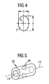
- the transverse bore 3 has a cross-sectional profile F, which in the direction of the central axis 2 has a maximum length a and perpendicular to a maximum width b has.
- the nail may also have other - not graphically illustrated transverse holes (round or oval).
- an insert 10 is provided for insertion into the transverse bore 3.
- the dimensioning of the insert 10 is congruent to the transverse bore 3, or is chosen such that when inserting a press fit results, thereby falling out of the insert from the transverse bore 3 is prevented.
- the insert 10 consists of material m lower strength, in particular a lower modulus of elasticity (compared to the material M of the intramedullary nail).
- the insert 10 may have a longitudinal bore 13 coaxial to its longitudinal bore 14 and a to his after insertion into the intramedullary nail perpendicular to the Kannulation corresponding transverse bore 24.
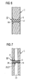
- FIG. 6 shows a variant of a one-piece insert 10 which consists of a pin 17 with a conically widened head 18.
- a further variant of a one-piece insert 10 which consists of a centrally pierced pin 19 with a plurality of peripheral, conical extensions 20, which in corresponding cavities 21, respectively in the longitudinal bore 23 in the transverse bore 3 in the form of a click closure can intervene.
Description
- Die Erfindung betrifft einen chirurgischen Nagel, insbesondere einen intramedullären Marknagel, gemäss dem Oberbegriff des Patentanspruchs 1.
- Die Verriegelung von Marknägeln gehört zum Stand der Technik. Die Einführung der Verriegelungsschrauben, oder Verriegelungsbolzen (im folgenden wird nur noch der Begriff Verriegelungsschraube verwendet, der aber auch den Begriff Verriegelungsbolzen mitumfassen soll) in die Querbohrungen eines Marknagels erfolgt entweder mit Hilfe eines bildgebenden Verfahrens (Röntgenkontrolle) oder einer mehr oder weniger komplizierten Zielvorrichtung. In beiden Fällen ist eine gewisse Zielungenauigkeit nicht zu vermeiden, d.h. die Schraubenspitze lässt sich nicht exakt koaxial zur Mittelachse der Querbohrung ausrichten, sondern weicht davon um einen gewissen Betrag ab. Damit die Verriegelungsschraube trotz dieses Zielfehlers in die Querbohrung mündet und durch diese hindurchgebracht werden kann, wird der Aussendurchmesser der Schraube relativ zum Durchmesser der Querbohrung unterdimensioniert. Bleibt die Zielungenauigkeit im Rahmen dieser Unterdimensionierung, so kann die Verriegelungsschraube trotz des Zielfehlers problemlos durch die Querbohrung geführt werden. Allerdings weist nun die Verriegelungsschraube - wegen der Unterdimensionierung - ein gewisses Spiel auf relativ zur Querbohrung.
- Dieses Spiel definiert, um welchen Betrag sich die Knochenhauptfragmente, welche mittels Verriegelungsschrauben im entsprechenden Verriegelungsloch fixiert werden, relativ zum Nagel und somit aufgrund der Starrheit des Nagels auch relativ zu anderen mit demselben Nagel befestigten Knochenhauptfragmente bewegen können. Um die Anwendbarkeit der Verriegelung für den Chirurgen zu garantieren, ist dieses Spiel zwar unumgänglich, doch ist es klinisch bei gewissen Indikationen (z.B. im Falle von metaphysären Fragmenten) unerwünscht.
- Selbst Nägel mit vollem Querschnitt, welche im Verriegelungsloch ein Innengewinde aufweisen können, sind nicht spielfrei. Das Innengewinde verhindert lediglich, dass der Nagel sich axial auf der Verriegelungsschraube verschieben kann.
- Aus der
US 6,296,645 HOVER ET AL. ist ein hohler, intramedullärer Marknagel aus Metall bekannt, der in den als Fenster bezeichneten sich diametral gegenüberstehenden Mantelöffnungen der Querbohrung einen oder zwei Kunststoffeinsätze aufweist, durch welche die Verriegelungsschraube eingeführt werden kann. Nachteilig bei diesem bekannten Marknagel ist der Umstand, dass die fensterartigen Kunststoffeinsätze leicht eingedrückt werden können, so dass die erwünschte Funktion verloren geht. Aber selbst bei einer sehr vorsichtigen Manipulation dürften die beiden Kunststoffeinsätze beim Durchführen der Verriegelungsschraube aus ihrem "Fenster" gedrückt werden, was ebenfalls zu einem Verlust der Funktion führt. - Weitere Marknägel mit Einsätzen sind aus der
WO-A-98/46169 US-A-2002/0173792 bekannt. - Hier will die Erfindung Abhilfe schaffen. Der Erfindung liegt die Aufgabe zugrunde, einen chirurgischen Nagel, insbesondere einen intramedullären Marknagel zu schaffen, mit dem das vorhandene Spiel zwischen ihm und der Verriegelungsschraube risikolos eliminiert werden kann und eine verbesserte Haltekraft sowie ein verbesserter Führungseffekt zwischen Verriegelungsschraube und Marknagel erzielt werden kann.
- Die Erfindung löst die gestellte Aufgabe mit einem chirurgischen Nagel, welcher die Merkmale des Anspruchs 1 aufweist.
- Damit sind folgenden Vorteile erzielbar:
- a) die Zielgenauigkeit bei der Einbringung der Verriegelungsschraube ist unbeeinträchtigt;
- b) der Arzt kann noch intraoperativ wählen, ob er eine winkelstabile Verriegelung der Verriegelungsschraube einsetzen will oder nicht, wobei der Begriff "winkelstabil" eine Einschränkung gewisser Freiheitsgrade bedeutet;
- c) Möglichkeit der winkelstabilen Fixierung des Knochenfragments in gewissen Richtungen für einen bestimmten Betrag der Last; und
- d) Nagel und Einsatz können separat steril verpackt werden und der Chirurg kann wählen ob er den Nagel ohne Einsatz öder mit Einsatz verwenden will. In letzterem Fall kann der Chirurg den Einsatz selbst in Nagel einführen und gegebenenfalls auch wieder entfernen. Verwendet der Chirurg den Nagel ohne Einsatz so bleibt dieser weiterhin steril verpackt für eine nächste Verwendung.
- Bei einer besonderen Ausführungsform gehorcht die Länge L des Einsatzes der Bedingung L > 0,5 D und vorzugsweise L = D.
- Bei einer weiteren Ausführungsform ist der Einsatz im wesentlichen kongruent zur Querbohrung.
- Bei einer besonderen Ausführungsform kann der Einsatz eine zu seiner Längsachse koaxiale Bohrung aufweist, um das Einführen der Verriegelungsschraube zu erleichtern.
- Vorteilhafterweise weist Material m des Einsatzes eine Zugfestigkeit fz < Fz, eine Druckfestigkeit fd < Fd sowie ein Elastizitätsmodul e < 0,8 E, vorzugsweise e < 0,7 E auf.
- Bei einer Ausführungsform ist das Material m des Einsatzes ein biokompatibler Kunststoff, vorzugsweise ein Polyethylen oder ein hochmolekulares Polyethylen (HMWPE), was den Vorteil mit sich bringt, dass kein Abbau des Kunststoffs mit unbekannten Abbauprodukten erfolgt.
- Eine bevorzugte Weiterbildung besteht darin, dass der Einsatz aus einem Material geringerer Härte ein bioresorbierbares Polymer, vorzugsweise ein Polylactid ist. Bei dieser Ausführung resultiert anfänglich eine spielfreie Querverriegelung des Marknagels, welche dann mit zunehmender Resorption des Polymers sukzessive wieder aufgehoben wird, so dass die Querverriegelungsschraube relativ zum Marknagel und somit auch die versorgten Knochenfragmente wieder beweglich werden. Es erfolgt somit eine Dynamisierung der Knochenfragmente nach erfolgter Frakturkonsolidierung. Das bioresorbierbare Material hat den Vorteil, dass die beim Hindurchschrauben einer Verriegelungsschraube durch den Nagel entstehenden Späne vom Körper abgebaut werden können. Ein weiterer Vorteil besteht in der Möglichkeit eine eventuell zeitlich unterschiedliche Stärke der winkelstabilen Verriegelung der Verriegelungsschraube zu realisieren, d.h. einen graduellen Abbau der Haltekraft zu erreichen.
- Die Querbohrung des Marknagels kann entweder eine Kreisbohrung sein, wobei das Querschnittsprofil F die maximalen Längen a = b aufweist (d.h. a = b ist der Durchmesser Querbohrung) oder auch als Langloch ausgebildet sein, wobei dann das Querschnittsprofil F die maximalen Längen a > b aufweist.
- Das Material m des Einsatzes weist vorteilhafterweise auch eine geringere Dichte ρ1 als das Material M mit der Dichte ρ2 auf, wobei vorzugsweise ρ1 < 0,8 ρ2 ist.
- Die durch den Einsatz hindurchführbare Verriegelungsschraube, bzw. Verriegelungsbolzen sollte vorzugsweise einen Schaft mit dem Durchmesser d aufweisen (maximaler Durchmesser, der auch ein allfälliges Aussengewinde mitumfasst), welcher den Bedingungen a > d < b gehorcht. Der Durchmesser d des Schraubengewindes sollte dabei vorzugsweise mindestens 5 % kleiner sein als die kleinere der beiden Dimensionen a, b.
- Bei einer speziellen Ausführungsform erweitert sich die Querbohrung gegen die Oberfläche des Nagels hin, vorzugsweise in Form eines konischen Abschnittes. Dies hat den Vorteil, das ein darin eingeführter Einsatz mit einem dazu korrespondierenden konischen Abschnitt sich nicht mehr axial in Einführrichtung verschieben kann.
- Die Erfindung und Weiterbildungen der Erfindung werden im folgenden anhand der teilweise schematischen Darstellungen mehrerer Ausführungsbeispiele noch näher erläutert.
- Es zeigen:
- Fig. 1 eine perspektivische Ansicht eines durchgängig kannulierten Marknagels mit einer Querbohrung und einen dazu passenden Einsatz sowie eine Querverriegelungsschraube;
- Fig. 2 einen Längsschnitt durch den Marknagel nach Fig. 1;
- Fig. 3 einen um 90° verdrehten Längsschnitt durch den Marknagel nach Fig. 1;
- Fig. 4 eine vergrösserte schematische Ansicht des Profils der Querbohrung des Marknagels nach Fig. 1;
- Fig. 5 einen einteiligen Einsatz mit einer Längsbohrung für die Querbohrung im Marknagel, welcher nach dem Einsetzen in etwa mit der Nagelkannulierung fluchtet;
- Fig. 6 einen partiellen Längsschnitt durch einen weiteren, modifizierten Marknagel mit einem modifizierten einteiligen Einsatz; und
- Fig. 7 einen partiellen Längsschnitt durch einen weiteren, modifizierten Marknagel mit einem modifizierten einteiligen Einsatz.
- Der in den Fig. 1 - 3 dargestellte chirurgische Nagel 1 ist ein intramedullärer Marknagel für Röhrenknochen mit einer Zentralachse 2, der aus einem Metall oder einer Metalllegierung, d.h. einem Material mit relativ hoher Festigkeit (Zugfestigkeit Fz, Druckfestigkeit Fd und Elastizitätsmodul E) besteht. Der Nagel 1 besitzt eine zur Zentralachse 2 verlaufende, als Langloch mit dem Querschnittsprofil F ausgebildete Querbohrung 3 mit der Querachse 4. Wie in Fig. 4 dargestellt weist die Querbohrung 3 ein Querschnittsprofil F auf, welches in Richtung der Zentralachse 2 eine maximale Länge a und senkrecht dazu eine maximale Breite b aufweist. Der Nagel kann auch noch weitere - zeichnerisch nicht dargestellte Querbohrungen (rund oder oval) aufweisen.
- Wie in Fig. 1 dargestellt, ist ein Einsatz 10 zur Einführung in die Querbohrung 3 vorgesehen. Die Dimensionierung des Einsatzes 10 ist kongruent zur Querbohrung 3, bzw. ist derart gewählt dass bei der Insertion ein Presssitz resultiert, wodurch ein Herausfallen des Einsatzes aus der Querbohrung 3 verhindert wird. Der Einsatz 10 besteht aus Material m geringerer Festigkeit, insbesondere einem geringeren E-Modul (im Vergleich zum Material M des Marknagels).
- Wie in Fig. 5 dargestellt kann der Einsatz 10 eine zu seiner Längsachse 13 koaxiale Längsbohrung 14 und eine zu seiner nach dem Einsetzen in den Marknagel senkrecht mit dessen Kannulierung korrespondierende Querbohrung 24 aufweisen.
- In Fig. 6 ist eine Variante eines einteiligen Einsatzes 10 dargestellt der aus einem Stift 17 mit konischem erweitertem Kopf 18 besteht.
- In Fig. 7 ist eine weitere Variante eines einteiligen Einsatzes 10 dargestellt der aus einem zentral durchbohrten Stift 19 mit mehreren peripheren angeordneten, konischen Erweiterungen 20 besteht, welche in entsprechende Kavitäten 21, respektive in der Längsbohrung 23 im Bereich der Querbohrung 3 im Form eines Klickverschlusses eingreifen können.
Claims (16)
- Chirurgischer Nagel (1), insbesondere intramedullärer Marknagel, mit einer Zentralachse (2), der aus einem Material M mit der Zugfestigkeit Fz, der Druckfestigkeit Fd, der Dichte ρ2 und dem Elastizitätsmodul E besteht und mindestens eine quer zur Zentralachse (2) verlaufenden Querbohrung (3) mit dem Querschnittsprofil F und einer Querachse (4) aufweist, wobei das Querschnittsprofil F in Richtung der Zentralachse eine maximale Länge a und senkrecht dazu eine maximale Breite b aufweist und der Marknagel im Bereich der Querbohrung (3) einen Durchmesser D aufweist und der Nagel (1) einen in die Querbohrung (3) einführbaren Einsatz (10) mit der Längsachse (13) umfasst, welcher aus einem Material m besteht, der ein geringeres Elastizitätsmodul e < E aufweist als das Material M, wobei der Einsatz (10) eine in Richtung seiner Längsachse (13) gemessene Länge L aufweist, welche der Bedingung L > 0,2 D gehorcht;
dadurch gekennzeichnet, dass
der Einsatz (10) aus einem zentral durchbohrten Stift (19) mit mehreren peripher angeordneten, konischen Erweiterungen (20) besteht, welche in entsprechende Kavitäten (21), respektive in der Längsbohrung (23) im Bereich der Querbohrung (3) in Form eines Klickverschlusses eingreifen können. - Nagel (1) nach Anspruch 1, dadurch gekennzeichnet, dass L > 0,5 D und vorzugsweise L = D ist.
- Nagel (1) nach Anspruch 1 oder 2, dadurch gekennzeichnet, dass der Einsatz (10) im wesentlichen kongruent zur Querbohrung (3) ist.
- Nagel (1) nach Anspruch 1, dadurch gekennzeichnet, dass der Einsatz (10) eine zu seiner Längsachse (13) koaxiale Bohrung (14) aufweist.
- Nagel (1) nach einem der Ansprüche 1 bis 3, dadurch gekennzeichnet, dass das Elastizitätsmodul e < 0,8 E, vorzugsweise e < 0,7 E ist.
- Nagel (1) nach einem der Ansprüche 1 bis 5, dadurch gekennzeichnet, dass das Material m eine Zugfestigkeit fz < Fz aufweist.
- Nagel (1) nach einem der Ansprüche 1 bis 6, dadurch gekennzeichnet, dass das Material m eine Druckfestigkeit fd < Fd aufweist.
- Nagel (1) nach einem der Ansprüche 1 bis 7, dadurch gekennzeichnet, dass das Material m ein biokompatibler Kunststoff, vorzugsweise ein Polyethylen oder ein hochmolekulares Polyethylen (HMWPE) ist.
- Nagel (1) nach einem der Ansprüche 1 bis 8, dadurch gekennzeichnet, dass der Kunststoff ein bioresorbierbares Polymer oder Copolymer, vorzugsweise ein Polylactid ist.
- Nagel (1) nach einem der Ansprüche 1 bis 9, dadurch gekennzeichnet, dass die Querbohrung (3) eine Kreisbohrung ist, wobei das Querschnittsprofile F die maximalen Längen a = b aufweist.
- Nagel (1) nach einem der Ansprüche 1 bis 10, dadurch gekennzeichnet, dass die Querbohrung (3) als Langloch ausgebildet ist, wobei das Querschnittsprofile F die maximalen Längen a > b aufweist.
- Nagel (1) nach einem der Ansprüche 1 bis 11, dadurch gekennzeichnet, dass das Material m auch eine geringere Dichte ρ1 als das Material M mit der Dichte ρ2 aufweist, wobei vorzugsweise ρ1 < 0,8 ρ2 ist.
- Nagel (1) nach einem der Ansprüche 1 bis 12, dadurch gekennzeichnet, dass er eine in die Querbohrung (3) durch den Einsatz (10) hindurchführbare Verriegelungsschraube oder einen Verriegelungsbolzen umfasst, dessen Schaft einen Durchmesser d aufweist, welcher den Bedingungen a > d < b gehorcht.
- Nagel (1) nach einem der Ansprüche 1 bis 13, dadurch gekennzeichnet, dass sich die Querbohrung (3) gegen die Oberfläche des Nagels (1) hin erweitert, vorzugsweise in Form eines konischen Abschnittes
- Nagel (1) nach einem der Ansprüche 1 bis 14, dadurch gekennzeichnet, dass er eine Verriegelungsschraube (30) mit einem Schraubenschaft (31) und einem Aussengewinde (32) umfasst, wobei für den Durchmesser d des Schraubengewindes (32) a > d < b gilt, und d vorzugsweise mindestens 5 % kleiner ist als die kleinere der beiden Dimensionen a, b.
- Nagel (1) nach einem der Ansprüche 1 bis 15, dadurch gekennzeichnet, dass der Einsatz (10) aus einem Stift (17) mit konischem erweitertem Kopf (18) besteht.
Applications Claiming Priority (1)
| Application Number | Priority Date | Filing Date | Title |
|---|---|---|---|
| PCT/CH2003/000376 WO2004110291A1 (de) | 2003-06-12 | 2003-06-12 | Chirurgischer nagel |
Publications (2)
| Publication Number | Publication Date |
|---|---|
| EP1631206A1 EP1631206A1 (de) | 2006-03-08 |
| EP1631206B1 true EP1631206B1 (de) | 2007-10-10 |
Family
ID=33546137
Family Applications (1)
| Application Number | Title | Priority Date | Filing Date |
|---|---|---|---|
| EP03817232A Expired - Lifetime EP1631206B1 (de) | 2003-06-12 | 2003-06-12 | Chirurgischer nagel |
Country Status (15)
| Country | Link |
|---|---|
| US (1) | US9737347B2 (de) |
| EP (1) | EP1631206B1 (de) |
| JP (1) | JP4357478B2 (de) |
| CN (1) | CN100457058C (de) |
| AR (1) | AR044330A1 (de) |
| AT (1) | ATE375125T1 (de) |
| AU (1) | AU2003232567B2 (de) |
| BR (1) | BR0318327B1 (de) |
| CA (1) | CA2531541C (de) |
| CL (1) | CL2004000867A1 (de) |
| DE (1) | DE50308380D1 (de) |
| ES (1) | ES2294372T3 (de) |
| NZ (1) | NZ544074A (de) |
| TW (1) | TWI323169B (de) |
| WO (1) | WO2004110291A1 (de) |
Families Citing this family (32)
| Publication number | Priority date | Publication date | Assignee | Title |
|---|---|---|---|---|
| DE20300987U1 (de) | 2003-01-23 | 2003-04-10 | Stryker Trauma Gmbh | Implantat für die Osteosynthese |
| EP1596765A2 (de) * | 2003-02-10 | 2005-11-23 | Smith & Nephew, Inc. | Resorbierbare vorrichtungen |
| EP2263584B1 (de) * | 2003-03-07 | 2012-09-05 | Synthes GmbH | Marknagel mit Verriegelungsschraube |
| ATE477757T1 (de) * | 2003-03-21 | 2010-09-15 | Synthes Gmbh | Intramedullärer marknagel |
| ATE476148T1 (de) * | 2003-06-12 | 2010-08-15 | Synthes Gmbh | Chirurgischer nagel |
| WO2005009263A1 (de) * | 2003-07-30 | 2005-02-03 | Synthes Ag Chur | Chirurgischer nagel |
| WO2005020830A1 (de) | 2003-08-29 | 2005-03-10 | Synthes Gmbh | Marknagel |
| NZ546545A (en) * | 2003-10-21 | 2008-11-28 | Synthes Gmbh | Intramedullary nail |
| GB0329654D0 (en) | 2003-12-23 | 2004-01-28 | Smith & Nephew | Tunable segmented polyacetal |
| CA2571469C (en) * | 2004-06-22 | 2012-09-25 | Synthes (U.S.A.) | Intramedullary nail |
| CA2571672C (en) * | 2004-06-24 | 2012-08-28 | Synthes (U.S.A.) | Intramedullary nail |
| EP1761182B1 (de) * | 2004-06-30 | 2011-04-06 | Synthes GmbH | Chirurgischer nagel |
| CA2619571A1 (en) * | 2005-08-18 | 2007-02-22 | Smith & Nephew, Plc | High strength devices and composites |
| US9005201B2 (en) | 2006-04-06 | 2015-04-14 | Halifax Biomedical Inc. | Intramedullary rod with vent |
| CN101594831B (zh) | 2006-11-30 | 2011-09-14 | 史密夫和内修有限公司 | 纤维增强的复合材料 |
| JP5416090B2 (ja) | 2007-04-18 | 2014-02-12 | スミス アンド ネフュー ピーエルシー | 形状記憶ポリマーの膨張成形 |
| EP2142227B1 (de) | 2007-04-19 | 2012-02-29 | Smith & Nephew, Inc. | Multimodale formgedächtnis-polymere |
| DE602008006181D1 (de) | 2007-04-19 | 2011-05-26 | Smith & Nephew Inc | Graft-fixierung |
| US20100114097A1 (en) * | 2007-04-27 | 2010-05-06 | Synthes Usa, Llc | Implant Devices Constructed with Metallic and Polymeric Components |
| US9597129B2 (en) | 2007-05-25 | 2017-03-21 | Zimmer Gmbh | Reinforced intramedullary nail |
| CN102176873A (zh) | 2008-10-15 | 2011-09-07 | 捷迈有限公司 | 髓内钉 |
| FR2968373B1 (fr) * | 2010-12-07 | 2013-01-04 | Skf Ab | Roulement pour dispositif de galet tendeur et galet tendeur associe |
| US20130053847A1 (en) | 2011-08-31 | 2013-02-28 | Mark Siravo | Implant Devices Constructed with Metallic and Polymeric Components |
| KR101415316B1 (ko) | 2012-06-01 | 2014-07-04 | 유앤아이 주식회사 | 와이어타입 네일 어셈블리 |
| DE102013005414A1 (de) * | 2013-03-28 | 2014-10-02 | Dietmar Wolter | Osteosynthesesystem für die multidirektionale, winkelstabile Versorgung von Frakturen von Röhrenknochen umfassend einen Marknagel und Knochenschrauben |
| US9526542B2 (en) | 2014-05-07 | 2016-12-27 | Acumed Llc | Hip fixation with load-controlled dynamization |
| US10080596B2 (en) | 2013-12-09 | 2018-09-25 | Acumed Llc | Hip fixation with load-controlled dynamization |
| JP6486363B2 (ja) | 2013-12-09 | 2019-03-20 | アキュームド・エルエルシー | プレートに基づく柔軟な股関節固定システム |
| US9433451B2 (en) | 2013-12-09 | 2016-09-06 | Acumed Llc | Hip fixation system with a compliant fixation element |
| PT3079612T (pt) | 2013-12-09 | 2020-07-16 | Acumed Llc | Sistema de fixação de anca compatível à base de hastes |
| WO2019140438A1 (en) | 2018-01-15 | 2019-07-18 | Sands Steven Saam | Hybrid intramedullary rods |
| US11617604B2 (en) | 2020-04-15 | 2023-04-04 | DePuy Synthes Products, Inc. | Intramedullary nail assembly |
Family Cites Families (92)
| Publication number | Priority date | Publication date | Assignee | Title |
|---|---|---|---|---|
| US2834342A (en) | 1956-08-29 | 1958-05-13 | Clyde E Yost | Surgical device for the fixation of fractured bones |
| US3112743A (en) | 1960-09-01 | 1963-12-03 | Orthopaedic Specialties Corp | Method for treatment of bone fractures |
| US3433220A (en) | 1966-12-30 | 1969-03-18 | Robert E Zickel | Intramedullary rod and cross-nail assembly for treating femur fractures |
| US4095591A (en) | 1977-01-27 | 1978-06-20 | Richards Manufacturing Co., Inc. | Compression screw system |
| US4103683A (en) | 1977-06-03 | 1978-08-01 | Neufeld John A | Sub-trochanteric nail |
| US4172452A (en) | 1978-05-15 | 1979-10-30 | Howmedica, Inc. | Fracture nail plate assembly |
| US4274163A (en) | 1979-07-16 | 1981-06-23 | The Regents Of The University Of California | Prosthetic fixation technique |
| US4494535A (en) | 1981-06-24 | 1985-01-22 | Haig Armen C | Hip nail |
| US4438762A (en) | 1981-12-30 | 1984-03-27 | Richard F. Kyle | Orthopedic hip fixation device |
| DE3332642A1 (de) | 1983-09-09 | 1985-04-04 | Ortopedia Gmbh, 2300 Kiel | Vorrichtung zum auffinden von querbohrungen intramedullaerer implantate |
| CH668173A5 (de) | 1984-05-14 | 1988-12-15 | Synthes Ag | Vorrichtung zum fixieren von roehrenknochenfrakturen mit einem knochenmarknagel und mindestens einem zur verriegelung dienenden querbolzen. |
| US4657001A (en) | 1984-07-25 | 1987-04-14 | Fixel Irving E | Antirotational hip screw |
| US4612920A (en) | 1984-11-06 | 1986-09-23 | Zimmer, Inc. | Compression hip screw |
| US4697585A (en) | 1985-01-11 | 1987-10-06 | Williams Michael O | Appliance for fixing fractures of the femur |
| US4622959A (en) | 1985-03-05 | 1986-11-18 | Marcus Randall E | Multi-use femoral intramedullary nail |
| DE3534747A1 (de) | 1985-09-28 | 1987-04-09 | Hasselbach Christoph Von | Schenkelhalsimplantat |
| US4754749A (en) | 1986-04-29 | 1988-07-05 | Tsou Paul M | Surgical screw with counter-rotation prevention means |
| US4776330A (en) | 1986-06-23 | 1988-10-11 | Pfizer Hospital Products Group, Inc. | Modular femoral fixation system |
| US5312406A (en) | 1986-12-30 | 1994-05-17 | Smith & Nephew Richards Inc. | Method of treating an intertrochanteric fracture |
| US5167663A (en) | 1986-12-30 | 1992-12-01 | Smith & Nephew Richards Inc. | Femoral fracture device |
| US4978270A (en) * | 1987-07-31 | 1990-12-18 | Akh, Inc. | Headless rivet |
| GB8722370D0 (en) | 1987-09-23 | 1987-10-28 | Halder S C | Fixating device |
| US5176681A (en) | 1987-12-14 | 1993-01-05 | Howmedica International Inc. | Intramedullary intertrochanteric fracture fixation appliance and fitting device |
| CH674613A5 (de) | 1988-03-14 | 1990-06-29 | Synthes Ag | |
| US4973332A (en) | 1988-09-12 | 1990-11-27 | Hospital For Joint Diseases | Attachment for femur sliding screw plate |
| US5066296A (en) | 1989-02-02 | 1991-11-19 | Pfizer Hopsital Products Group, Inc. | Apparatus for treating a fracture |
| US4978349A (en) | 1989-08-03 | 1990-12-18 | Synthes (U.S.A.) | Fixation plate |
| US5032125A (en) | 1990-02-06 | 1991-07-16 | Smith & Nephew Richards Inc. | Intramedullary hip screw |
| US5120171A (en) | 1990-11-27 | 1992-06-09 | Stuart Surgical | Bone screw with improved threads |
| CH682300A5 (de) | 1990-12-17 | 1993-08-31 | Synthes Ag | |
| GB9113578D0 (en) * | 1991-06-24 | 1991-08-14 | Howmedica | Intramedullary intertrochanteric fracture fixation appliance |
| DE9109883U1 (de) | 1991-08-09 | 1991-09-26 | Howmedica Gmbh, 2314 Schoenkirchen, De | |
| DE4205118C1 (de) * | 1992-02-13 | 1993-07-29 | Dietmar Dr.Med. Priv. Doz. 5000 Koeln De Pennig | |
| DE4318150C2 (de) | 1993-06-01 | 1996-08-01 | Endocare Ag | Osteosynthese-Hilfsmittel zur Versorgung subtrochanterer und pertrochanterer Frakturen sowie von Schenkelhalsfrakturen |
| US5484439A (en) | 1992-09-16 | 1996-01-16 | Alphatec Manufacturing, Inc. | Modular femur fixation device |
| FR2698261B1 (fr) * | 1992-11-24 | 1995-03-17 | Lacaffiniere Jean Yves De | Dispositif de guidage d'une double vis du col du fémur pour clou trochantéro-diaphysaire verrouillé. |
| IT1261494B (it) | 1993-07-30 | 1996-05-23 | Gideon Raphael Tock | Chiodo endomidollare e osteosintesi reticolati, componibili per l'applicazione in ortopedia senza l'esposizione a raggi ionizzanti. |
| FR2711505B1 (fr) | 1993-10-25 | 1995-12-29 | Tornier Sa | Dispositif de synthèse des fractures de l'extrémité supérieure du fémur. |
| CH688222A5 (de) | 1993-12-07 | 1997-06-30 | Synthes Ag | Knochenfixationselement. |
| EP0668059B1 (de) | 1994-02-21 | 2000-01-05 | Collux AB | Implantat für die Behandlung von Frakturen des Femur |
| US5549610A (en) | 1994-10-31 | 1996-08-27 | Smith & Nephew Richards Inc. | Femoral intramedullary nail |
| DE4442206A1 (de) | 1994-11-19 | 1996-05-23 | Artos Med Produkte | Gelenkprothese |
| US5976141A (en) * | 1995-02-23 | 1999-11-02 | Synthes (U.S.A.) | Threaded insert for bone plate screw hole |
| US5578035A (en) | 1995-05-16 | 1996-11-26 | Lin; Chih-I | Expandable bone marrow cavity fixation device |
| IT1275300B (it) | 1995-06-05 | 1997-08-05 | Gruppo Ind Bioimpianti Srl | Chiodo endomidollare bloccato adatto in particolare per le fratture del femore |
| JP3307804B2 (ja) | 1995-08-31 | 2002-07-24 | 瑞穂医科工業株式会社 | 髄内釘 |
| JP3307805B2 (ja) | 1995-08-31 | 2002-07-24 | 瑞穂医科工業株式会社 | 髄内釘 |
| JPH0966061A (ja) | 1995-08-31 | 1997-03-11 | Mizuho Ika Kogyo Kk | 髄内釘 |
| US5658339A (en) | 1996-01-05 | 1997-08-19 | Wright Medical Technology, Inc. | Compression hip screw plate |
| US5976139A (en) | 1996-07-17 | 1999-11-02 | Bramlet; Dale G. | Surgical fastener assembly |
| IT1287271B1 (it) | 1996-04-05 | 1998-08-04 | Antonio Chemello | Chiodo endomidollare per l'osteosintesi delle fratture delle ossa lunghe |
| DE19629011C2 (de) | 1996-07-18 | 2001-08-23 | Dietmar Wolter | Hilfsmittel für die Osteosynthese |
| ATE232064T1 (de) | 1996-07-31 | 2003-02-15 | Synthes Ag | Vorrichtung zum fixieren abgebrochener hüftgelenkköpfe |
| DE19633865A1 (de) | 1996-08-16 | 1998-02-19 | Guenter Prof Dr Med Lob | Endoprothese |
| IT242435Y1 (it) | 1996-10-24 | 2001-06-14 | Hit Medica Srl | Chiodo per la riduzione delle fratture trocanteriche e del collo delfemore. |
| DE29620327U1 (de) | 1996-11-22 | 1998-03-26 | Howmedica Gmbh | Verriegelungsnagel mit einstellbaren Öffnungen für Verriegelungsschrauben |
| US5741256A (en) | 1997-01-13 | 1998-04-21 | Synthes (U.S.A.) | Helical osteosynthetic implant |
| IT1293934B1 (it) | 1997-01-21 | 1999-03-11 | Orthofix Srl | Chiodo endomidollare per il trattamento delle fratture dell'anca |
| EP0865769A1 (de) | 1997-03-19 | 1998-09-23 | Osteo Ag | Modularer Marknagel |
| EP1342453B1 (de) | 1997-03-19 | 2005-08-24 | Stryker Trauma GmbH | Modularer Marknagel |
| US7255712B1 (en) * | 1997-04-15 | 2007-08-14 | Active Implants Corporation | Bone growth promoting implant |
| JP3311660B2 (ja) | 1997-11-12 | 2002-08-05 | 瑞穂医科工業株式会社 | 髄内釘 |
| EP0919200A1 (de) | 1997-11-20 | 1999-06-02 | VM Tech | Osteosynthesesystem für den Schenkelhalsbereich des Femurs |
| US5935127A (en) * | 1997-12-17 | 1999-08-10 | Biomet, Inc. | Apparatus and method for treatment of a fracture in a long bone |
| JP2000051225A (ja) | 1998-06-02 | 2000-02-22 | Ikushi Yamada | 髄内釘と遠位横止め方法 |
| DE19829228C1 (de) | 1998-06-30 | 1999-10-28 | Aesculap Ag & Co Kg | Vorrichtung zur Versorgung von Knochenbrüchen |
| JP2973316B1 (ja) | 1998-08-05 | 1999-11-08 | 洋司 村嶋 | インプラント用ネイルに用いるラグスクリューの固定構造 |
| US6010506A (en) | 1998-09-14 | 2000-01-04 | Smith & Nephew, Inc. | Intramedullary nail hybrid bow |
| FR2784283B1 (fr) | 1998-10-07 | 2000-12-15 | Fournitures Hospitalieres Ind | Clou medullaire d'osteosynthese |
| US6123708A (en) | 1999-02-03 | 2000-09-26 | Pioneer Laboratories, Inc. | Intramedullary bone fixation rod |
| US6296645B1 (en) * | 1999-04-09 | 2001-10-02 | Depuy Orthopaedics, Inc. | Intramedullary nail with non-metal spacers |
| US6783529B2 (en) * | 1999-04-09 | 2004-08-31 | Depuy Orthopaedics, Inc. | Non-metal inserts for bone support assembly |
| IL132742A0 (en) | 1999-05-11 | 2001-03-19 | S I N A I Medical Technologies | Osteosynthesis device for holding together in compression the parts of a fractured femur neck |
| EP1053718B1 (de) | 1999-05-12 | 2008-07-09 | Zimmer GmbH | Verriegelungsnagel zur Versorgung von Femurschaftfrakturen |
| JP2000342596A (ja) | 1999-06-07 | 2000-12-12 | Homuzu Giken:Kk | 髄内釘 |
| DE19945611B4 (de) | 1999-09-23 | 2005-11-24 | Aesculap Ag & Co. Kg | Proximaler Humerusnagel |
| US6926719B2 (en) | 1999-10-21 | 2005-08-09 | Gary W. Sohngen | Modular intramedullary nail |
| DK1233712T3 (da) * | 1999-12-03 | 2004-06-01 | Synthes Ag | Intramedullært söm |
| US6645209B2 (en) * | 2000-04-04 | 2003-11-11 | Synthes (Usa) | Device for rotational stabilization of bone segments |
| EP1214914B1 (de) | 2000-12-18 | 2004-05-19 | Bernsteiner, Helga Mag., | Verriegelungsschraube für Implantate |
| GB0102488D0 (en) | 2001-01-31 | 2001-03-14 | Grampian Univ Hospitals | Bone Fixture Apparatus |
| EP1260188B1 (de) | 2001-05-25 | 2014-09-17 | Zimmer GmbH | Oberschenkel-Marknagel zum Einbringen am Kniegelenk |
| US6652528B2 (en) * | 2001-07-17 | 2003-11-25 | Biomet, Inc. | Intramedullary nail with modular sleeve |
| DE20113345U1 (de) | 2001-08-17 | 2003-01-02 | Tantum Ag | Femurfrakturnagel |
| US20030069581A1 (en) | 2001-10-04 | 2003-04-10 | Stinson David T. | Universal intramedullary nails, systems and methods of use thereof |
| US6835197B2 (en) | 2001-10-17 | 2004-12-28 | Christoph Andreas Roth | Bone fixation system |
| EP2263584B1 (de) | 2003-03-07 | 2012-09-05 | Synthes GmbH | Marknagel mit Verriegelungsschraube |
| ATE477757T1 (de) | 2003-03-21 | 2010-09-15 | Synthes Gmbh | Intramedullärer marknagel |
| ATE476148T1 (de) | 2003-06-12 | 2010-08-15 | Synthes Gmbh | Chirurgischer nagel |
| WO2005009263A1 (de) | 2003-07-30 | 2005-02-03 | Synthes Ag Chur | Chirurgischer nagel |
| WO2005020830A1 (de) | 2003-08-29 | 2005-03-10 | Synthes Gmbh | Marknagel |
| NZ546545A (en) | 2003-10-21 | 2008-11-28 | Synthes Gmbh | Intramedullary nail |
-
2003
- 2003-06-12 BR BRPI0318327-0B1A patent/BR0318327B1/pt not_active IP Right Cessation
- 2003-06-12 DE DE50308380T patent/DE50308380D1/de not_active Expired - Lifetime
- 2003-06-12 AT AT03817232T patent/ATE375125T1/de not_active IP Right Cessation
- 2003-06-12 JP JP2005500667A patent/JP4357478B2/ja not_active Expired - Fee Related
- 2003-06-12 CA CA2531541A patent/CA2531541C/en not_active Expired - Fee Related
- 2003-06-12 AU AU2003232567A patent/AU2003232567B2/en not_active Ceased
- 2003-06-12 CN CNB038266156A patent/CN100457058C/zh not_active Expired - Fee Related
- 2003-06-12 WO PCT/CH2003/000376 patent/WO2004110291A1/de active IP Right Grant
- 2003-06-12 NZ NZ544074A patent/NZ544074A/xx not_active IP Right Cessation
- 2003-06-12 EP EP03817232A patent/EP1631206B1/de not_active Expired - Lifetime
- 2003-06-12 ES ES03817232T patent/ES2294372T3/es not_active Expired - Lifetime
-
2004
- 2004-04-23 CL CL200400867A patent/CL2004000867A1/es unknown
- 2004-04-27 TW TW093111714A patent/TWI323169B/zh not_active IP Right Cessation
- 2004-05-14 AR ARP040101642A patent/AR044330A1/es not_active Application Discontinuation
-
2005
- 2005-12-09 US US11/299,337 patent/US9737347B2/en active Active
Also Published As
| Publication number | Publication date |
|---|---|
| JP4357478B2 (ja) | 2009-11-04 |
| NZ544074A (en) | 2007-10-26 |
| ES2294372T3 (es) | 2008-04-01 |
| TW200505386A (en) | 2005-02-16 |
| DE50308380D1 (de) | 2007-11-22 |
| CA2531541C (en) | 2011-05-10 |
| AR044330A1 (es) | 2005-09-07 |
| US20060149248A1 (en) | 2006-07-06 |
| CL2004000867A1 (es) | 2005-01-14 |
| US9737347B2 (en) | 2017-08-22 |
| CN100457058C (zh) | 2009-02-04 |
| TWI323169B (en) | 2010-04-11 |
| BR0318327B1 (pt) | 2013-06-18 |
| BR0318327A (pt) | 2006-07-11 |
| ATE375125T1 (de) | 2007-10-15 |
| EP1631206A1 (de) | 2006-03-08 |
| CA2531541A1 (en) | 2004-12-23 |
| AU2003232567A1 (en) | 2005-01-04 |
| AU2003232567B2 (en) | 2007-12-20 |
| CN1787787A (zh) | 2006-06-14 |
| JP2006527004A (ja) | 2006-11-30 |
| WO2004110291A1 (de) | 2004-12-23 |
Similar Documents
| Publication | Publication Date | Title |
|---|---|---|
| EP1631206B1 (de) | Chirurgischer nagel | |
| EP1631205B1 (de) | Chirurgischer nagel | |
| EP1761182B1 (de) | Chirurgischer nagel | |
| EP1658013B1 (de) | Marknagel | |
| EP2263584B1 (de) | Marknagel mit Verriegelungsschraube | |
| EP1024762B1 (de) | Knochenfixationsvorrichtung | |
| DE10246386B4 (de) | Knochenschraube, Knochenfixationseinrichtung und Halteelement | |
| EP1830727B1 (de) | Marknagel | |
| EP1675514B1 (de) | Marknagel | |
| EP2213254B1 (de) | Chirurgisches Instrument | |
| WO1999062417A1 (de) | Chirurgische blindniete mit schliesselement | |
| EP0736286A2 (de) | Osteosynthese-Hilfsmittel zur Versorgung subtrochanterer, pertrochanterer und Schenkelhalsfrakturen | |
| EP1758513B1 (de) | Chirurgischer nagel | |
| EP1648321B1 (de) | Chirurgischer nagel | |
| EP1610701B1 (de) | Verriegelungsschraube | |
| EP2116204B1 (de) | Vorrichtung zur Stabilisierung von Röhrenknochenbrüchen | |
| DE4328015A1 (de) | Vorrichtung zum Behandeln von Knochen | |
| EP1771119B1 (de) | Schraube | |
| DE102007029090A1 (de) | Vorrichtung zur Osteosynthese gelenknaher Knochenfrakturen | |
| EP3742993B1 (de) | Intravertebrale schraube | |
| WO2003053265A1 (de) | Modularer knochennagel | |
| WO2004000144A1 (de) | Knochenschraube mit tangentialer schneidkante | |
| WO2007147688A1 (de) | Femurkopf-implantat | |
| DE102010023640B4 (de) | Nagel-Schrauben-System für winkelstabile Osteosynthese | |
| AT500081A1 (de) | Implantat zur gegenseitigen fixierung zweier knochenfragmente |
Legal Events
| Date | Code | Title | Description |
|---|---|---|---|
| PUAI | Public reference made under article 153(3) epc to a published international application that has entered the european phase |
Free format text: ORIGINAL CODE: 0009012 |
|
| 17P | Request for examination filed |
Effective date: 20051123 |
|
| AK | Designated contracting states |
Kind code of ref document: A1 Designated state(s): AT BE BG CH CY CZ DE DK EE ES FI FR GB GR HU IE IT LI LU MC NL PT RO SE SI SK TR |
|
| RIN1 | Information on inventor provided before grant (corrected) |
Inventor name: BUETTLER, MARKUS Inventor name: SCHLIENGER, ANDRE Inventor name: SENN, PETER |
|
| DAX | Request for extension of the european patent (deleted) | ||
| RAP1 | Party data changed (applicant data changed or rights of an application transferred) |
Owner name: SYNTHES GMBH |
|
| GRAP | Despatch of communication of intention to grant a patent |
Free format text: ORIGINAL CODE: EPIDOSNIGR1 |
|
| GRAS | Grant fee paid |
Free format text: ORIGINAL CODE: EPIDOSNIGR3 |
|
| GRAA | (expected) grant |
Free format text: ORIGINAL CODE: 0009210 |
|
| AK | Designated contracting states |
Kind code of ref document: B1 Designated state(s): AT BE BG CH CY CZ DE DK EE ES FI FR GB GR HU IE IT LI LU MC NL PT RO SE SI SK TR |
|
| REG | Reference to a national code |
Ref country code: GB Ref legal event code: FG4D Free format text: NOT ENGLISH |
|
| REG | Reference to a national code |
Ref country code: CH Ref legal event code: EP |
|
| REG | Reference to a national code |
Ref country code: IE Ref legal event code: FG4D Free format text: LANGUAGE OF EP DOCUMENT: GERMAN |
|
| REF | Corresponds to: |
Ref document number: 50308380 Country of ref document: DE Date of ref document: 20071122 Kind code of ref document: P |
|
| REG | Reference to a national code |
Ref country code: CH Ref legal event code: NV Representative=s name: DR. LUSUARDI AG |
|
| GBT | Gb: translation of ep patent filed (gb section 77(6)(a)/1977) |
Effective date: 20071128 |
|
| REG | Reference to a national code |
Ref country code: SE Ref legal event code: TRGR |
|
| NLV1 | Nl: lapsed or annulled due to failure to fulfill the requirements of art. 29p and 29m of the patents act | ||
| REG | Reference to a national code |
Ref country code: ES Ref legal event code: FG2A Ref document number: 2294372 Country of ref document: ES Kind code of ref document: T3 |
|
| ET | Fr: translation filed | ||
| PG25 | Lapsed in a contracting state [announced via postgrant information from national office to epo] |
Ref country code: NL Free format text: LAPSE BECAUSE OF FAILURE TO SUBMIT A TRANSLATION OF THE DESCRIPTION OR TO PAY THE FEE WITHIN THE PRESCRIBED TIME-LIMIT Effective date: 20071010 |
|
| PG25 | Lapsed in a contracting state [announced via postgrant information from national office to epo] |
Ref country code: BG Free format text: LAPSE BECAUSE OF FAILURE TO SUBMIT A TRANSLATION OF THE DESCRIPTION OR TO PAY THE FEE WITHIN THE PRESCRIBED TIME-LIMIT Effective date: 20080110 Ref country code: PT Free format text: LAPSE BECAUSE OF FAILURE TO SUBMIT A TRANSLATION OF THE DESCRIPTION OR TO PAY THE FEE WITHIN THE PRESCRIBED TIME-LIMIT Effective date: 20080310 |
|
| REG | Reference to a national code |
Ref country code: IE Ref legal event code: FD4D |
|
| REG | Reference to a national code |
Ref country code: HU Ref legal event code: AG4A Ref document number: E002842 Country of ref document: HU |
|
| PG25 | Lapsed in a contracting state [announced via postgrant information from national office to epo] |
Ref country code: CZ Free format text: LAPSE BECAUSE OF FAILURE TO SUBMIT A TRANSLATION OF THE DESCRIPTION OR TO PAY THE FEE WITHIN THE PRESCRIBED TIME-LIMIT Effective date: 20071010 Ref country code: DK Free format text: LAPSE BECAUSE OF FAILURE TO SUBMIT A TRANSLATION OF THE DESCRIPTION OR TO PAY THE FEE WITHIN THE PRESCRIBED TIME-LIMIT Effective date: 20071010 |
|
| PLBE | No opposition filed within time limit |
Free format text: ORIGINAL CODE: 0009261 |
|
| STAA | Information on the status of an ep patent application or granted ep patent |
Free format text: STATUS: NO OPPOSITION FILED WITHIN TIME LIMIT |
|
| PG25 | Lapsed in a contracting state [announced via postgrant information from national office to epo] |
Ref country code: RO Free format text: LAPSE BECAUSE OF FAILURE TO SUBMIT A TRANSLATION OF THE DESCRIPTION OR TO PAY THE FEE WITHIN THE PRESCRIBED TIME-LIMIT Effective date: 20071010 Ref country code: SK Free format text: LAPSE BECAUSE OF FAILURE TO SUBMIT A TRANSLATION OF THE DESCRIPTION OR TO PAY THE FEE WITHIN THE PRESCRIBED TIME-LIMIT Effective date: 20071010 |
|
| 26N | No opposition filed |
Effective date: 20080711 |
|
| PG25 | Lapsed in a contracting state [announced via postgrant information from national office to epo] |
Ref country code: IE Free format text: LAPSE BECAUSE OF FAILURE TO SUBMIT A TRANSLATION OF THE DESCRIPTION OR TO PAY THE FEE WITHIN THE PRESCRIBED TIME-LIMIT Effective date: 20071010 |
|
| BERE | Be: lapsed |
Owner name: YNTHES GMBH Effective date: 20080630 |
|
| PG25 | Lapsed in a contracting state [announced via postgrant information from national office to epo] |
Ref country code: GR Free format text: LAPSE BECAUSE OF FAILURE TO SUBMIT A TRANSLATION OF THE DESCRIPTION OR TO PAY THE FEE WITHIN THE PRESCRIBED TIME-LIMIT Effective date: 20080111 Ref country code: MC Free format text: LAPSE BECAUSE OF NON-PAYMENT OF DUE FEES Effective date: 20080630 |
|
| PG25 | Lapsed in a contracting state [announced via postgrant information from national office to epo] |
Ref country code: FI Free format text: LAPSE BECAUSE OF FAILURE TO SUBMIT A TRANSLATION OF THE DESCRIPTION OR TO PAY THE FEE WITHIN THE PRESCRIBED TIME-LIMIT Effective date: 20071010 |
|
| PG25 | Lapsed in a contracting state [announced via postgrant information from national office to epo] |
Ref country code: BE Free format text: LAPSE BECAUSE OF NON-PAYMENT OF DUE FEES Effective date: 20080630 |
|
| PG25 | Lapsed in a contracting state [announced via postgrant information from national office to epo] |
Ref country code: EE Free format text: LAPSE BECAUSE OF FAILURE TO SUBMIT A TRANSLATION OF THE DESCRIPTION OR TO PAY THE FEE WITHIN THE PRESCRIBED TIME-LIMIT Effective date: 20071010 |
|
| PG25 | Lapsed in a contracting state [announced via postgrant information from national office to epo] |
Ref country code: SI Free format text: LAPSE BECAUSE OF FAILURE TO SUBMIT A TRANSLATION OF THE DESCRIPTION OR TO PAY THE FEE WITHIN THE PRESCRIBED TIME-LIMIT Effective date: 20071010 |
|
| PG25 | Lapsed in a contracting state [announced via postgrant information from national office to epo] |
Ref country code: CY Free format text: LAPSE BECAUSE OF FAILURE TO SUBMIT A TRANSLATION OF THE DESCRIPTION OR TO PAY THE FEE WITHIN THE PRESCRIBED TIME-LIMIT Effective date: 20071010 |
|
| PG25 | Lapsed in a contracting state [announced via postgrant information from national office to epo] |
Ref country code: LU Free format text: LAPSE BECAUSE OF NON-PAYMENT OF DUE FEES Effective date: 20080612 |
|
| PGFP | Annual fee paid to national office [announced via postgrant information from national office to epo] |
Ref country code: HU Payment date: 20100527 Year of fee payment: 8 |
|
| PG25 | Lapsed in a contracting state [announced via postgrant information from national office to epo] |
Ref country code: TR Free format text: LAPSE BECAUSE OF FAILURE TO SUBMIT A TRANSLATION OF THE DESCRIPTION OR TO PAY THE FEE WITHIN THE PRESCRIBED TIME-LIMIT Effective date: 20071010 |
|
| PGFP | Annual fee paid to national office [announced via postgrant information from national office to epo] |
Ref country code: AT Payment date: 20100610 Year of fee payment: 8 |
|
| PGFP | Annual fee paid to national office [announced via postgrant information from national office to epo] |
Ref country code: SE Payment date: 20100609 Year of fee payment: 8 |
|
| REG | Reference to a national code |
Ref country code: SE Ref legal event code: EUG |
|
| PG25 | Lapsed in a contracting state [announced via postgrant information from national office to epo] |
Ref country code: AT Free format text: LAPSE BECAUSE OF NON-PAYMENT OF DUE FEES Effective date: 20110612 |
|
| REG | Reference to a national code |
Ref country code: AT Ref legal event code: MM01 Ref document number: 375125 Country of ref document: AT Kind code of ref document: T Effective date: 20110612 |
|
| PG25 | Lapsed in a contracting state [announced via postgrant information from national office to epo] |
Ref country code: HU Free format text: LAPSE BECAUSE OF NON-PAYMENT OF DUE FEES Effective date: 20110613 |
|
| PG25 | Lapsed in a contracting state [announced via postgrant information from national office to epo] |
Ref country code: SE Free format text: LAPSE BECAUSE OF NON-PAYMENT OF DUE FEES Effective date: 20110613 |
|
| PGFP | Annual fee paid to national office [announced via postgrant information from national office to epo] |
Ref country code: GB Payment date: 20140611 Year of fee payment: 12 |
|
| PGFP | Annual fee paid to national office [announced via postgrant information from national office to epo] |
Ref country code: ES Payment date: 20140513 Year of fee payment: 12 Ref country code: CH Payment date: 20140612 Year of fee payment: 12 Ref country code: DE Payment date: 20140603 Year of fee payment: 12 Ref country code: IT Payment date: 20140612 Year of fee payment: 12 |
|
| PGFP | Annual fee paid to national office [announced via postgrant information from national office to epo] |
Ref country code: FR Payment date: 20140609 Year of fee payment: 12 |
|
| REG | Reference to a national code |
Ref country code: DE Ref legal event code: R119 Ref document number: 50308380 Country of ref document: DE |
|
| PG25 | Lapsed in a contracting state [announced via postgrant information from national office to epo] |
Ref country code: IT Free format text: LAPSE BECAUSE OF NON-PAYMENT OF DUE FEES Effective date: 20150612 |
|
| REG | Reference to a national code |
Ref country code: CH Ref legal event code: PL |
|
| GBPC | Gb: european patent ceased through non-payment of renewal fee |
Effective date: 20150612 |
|
| REG | Reference to a national code |
Ref country code: FR Ref legal event code: ST Effective date: 20160229 |
|
| PG25 | Lapsed in a contracting state [announced via postgrant information from national office to epo] |
Ref country code: DE Free format text: LAPSE BECAUSE OF NON-PAYMENT OF DUE FEES Effective date: 20160101 Ref country code: CH Free format text: LAPSE BECAUSE OF NON-PAYMENT OF DUE FEES Effective date: 20150630 Ref country code: LI Free format text: LAPSE BECAUSE OF NON-PAYMENT OF DUE FEES Effective date: 20150630 Ref country code: GB Free format text: LAPSE BECAUSE OF NON-PAYMENT OF DUE FEES Effective date: 20150612 |
|
| PG25 | Lapsed in a contracting state [announced via postgrant information from national office to epo] |
Ref country code: FR Free format text: LAPSE BECAUSE OF NON-PAYMENT OF DUE FEES Effective date: 20150630 |
|
| REG | Reference to a national code |
Ref country code: ES Ref legal event code: FD2A Effective date: 20160728 |
|
| PG25 | Lapsed in a contracting state [announced via postgrant information from national office to epo] |
Ref country code: ES Free format text: LAPSE BECAUSE OF NON-PAYMENT OF DUE FEES Effective date: 20150613 |