EP1632937A2 - Data recording and readingout system - Google Patents
Data recording and readingout system Download PDFInfo
- Publication number
- EP1632937A2 EP1632937A2 EP05019117A EP05019117A EP1632937A2 EP 1632937 A2 EP1632937 A2 EP 1632937A2 EP 05019117 A EP05019117 A EP 05019117A EP 05019117 A EP05019117 A EP 05019117A EP 1632937 A2 EP1632937 A2 EP 1632937A2
- Authority
- EP
- European Patent Office
- Prior art keywords
- recording medium
- data
- layer
- optical
- optical recording
- Prior art date
- Legal status (The legal status is an assumption and is not a legal conclusion. Google has not performed a legal analysis and makes no representation as to the accuracy of the status listed.)
- Withdrawn
Links
Images

Classifications
-
- G—PHYSICS
- G11—INFORMATION STORAGE
- G11B—INFORMATION STORAGE BASED ON RELATIVE MOVEMENT BETWEEN RECORD CARRIER AND TRANSDUCER
- G11B7/00—Recording or reproducing by optical means, e.g. recording using a thermal beam of optical radiation by modifying optical properties or the physical structure, reproducing using an optical beam at lower power by sensing optical properties; Record carriers therefor
- G11B7/24—Record carriers characterised by shape, structure or physical properties, or by the selection of the material
- G11B7/2407—Tracks or pits; Shape, structure or physical properties thereof
- G11B7/24085—Pits
-
- G—PHYSICS
- G11—INFORMATION STORAGE
- G11B—INFORMATION STORAGE BASED ON RELATIVE MOVEMENT BETWEEN RECORD CARRIER AND TRANSDUCER
- G11B7/00—Recording or reproducing by optical means, e.g. recording using a thermal beam of optical radiation by modifying optical properties or the physical structure, reproducing using an optical beam at lower power by sensing optical properties; Record carriers therefor
- G11B7/12—Heads, e.g. forming of the optical beam spot or modulation of the optical beam
- G11B7/122—Flying-type heads, e.g. analogous to Winchester type in magnetic recording
-
- G—PHYSICS
- G11—INFORMATION STORAGE
- G11B—INFORMATION STORAGE BASED ON RELATIVE MOVEMENT BETWEEN RECORD CARRIER AND TRANSDUCER
- G11B7/00—Recording or reproducing by optical means, e.g. recording using a thermal beam of optical radiation by modifying optical properties or the physical structure, reproducing using an optical beam at lower power by sensing optical properties; Record carriers therefor
- G11B7/12—Heads, e.g. forming of the optical beam spot or modulation of the optical beam
- G11B7/135—Means for guiding the beam from the source to the record carrier or from the record carrier to the detector
- G11B7/1387—Means for guiding the beam from the source to the record carrier or from the record carrier to the detector using the near-field effect
-
- G—PHYSICS
- G11—INFORMATION STORAGE
- G11B—INFORMATION STORAGE BASED ON RELATIVE MOVEMENT BETWEEN RECORD CARRIER AND TRANSDUCER
- G11B7/00—Recording or reproducing by optical means, e.g. recording using a thermal beam of optical radiation by modifying optical properties or the physical structure, reproducing using an optical beam at lower power by sensing optical properties; Record carriers therefor
- G11B7/24—Record carriers characterised by shape, structure or physical properties, or by the selection of the material
- G11B7/241—Record carriers characterised by shape, structure or physical properties, or by the selection of the material characterised by the selection of the material
- G11B7/242—Record carriers characterised by shape, structure or physical properties, or by the selection of the material characterised by the selection of the material of recording layers
- G11B7/243—Record carriers characterised by shape, structure or physical properties, or by the selection of the material characterised by the selection of the material of recording layers comprising inorganic materials only, e.g. ablative layers
-
- G—PHYSICS
- G11—INFORMATION STORAGE
- G11B—INFORMATION STORAGE BASED ON RELATIVE MOVEMENT BETWEEN RECORD CARRIER AND TRANSDUCER
- G11B7/00—Recording or reproducing by optical means, e.g. recording using a thermal beam of optical radiation by modifying optical properties or the physical structure, reproducing using an optical beam at lower power by sensing optical properties; Record carriers therefor
- G11B7/24—Record carriers characterised by shape, structure or physical properties, or by the selection of the material
- G11B7/241—Record carriers characterised by shape, structure or physical properties, or by the selection of the material characterised by the selection of the material
- G11B7/252—Record carriers characterised by shape, structure or physical properties, or by the selection of the material characterised by the selection of the material of layers other than recording layers
- G11B7/257—Record carriers characterised by shape, structure or physical properties, or by the selection of the material characterised by the selection of the material of layers other than recording layers of layers having properties involved in recording or reproduction, e.g. optical interference layers or sensitising layers or dielectric layers, which are protecting the recording layers
-
- G—PHYSICS
- G11—INFORMATION STORAGE
- G11B—INFORMATION STORAGE BASED ON RELATIVE MOVEMENT BETWEEN RECORD CARRIER AND TRANSDUCER
- G11B7/00—Recording or reproducing by optical means, e.g. recording using a thermal beam of optical radiation by modifying optical properties or the physical structure, reproducing using an optical beam at lower power by sensing optical properties; Record carriers therefor
- G11B7/12—Heads, e.g. forming of the optical beam spot or modulation of the optical beam
- G11B7/135—Means for guiding the beam from the source to the record carrier or from the record carrier to the detector
- G11B7/1372—Lenses
- G11B2007/13727—Compound lenses, i.e. two or more lenses co-operating to perform a function, e.g. compound objective lens including a solid immersion lens, positive and negative lenses either bonded together or with adjustable spacing
-
- G—PHYSICS
- G11—INFORMATION STORAGE
- G11B—INFORMATION STORAGE BASED ON RELATIVE MOVEMENT BETWEEN RECORD CARRIER AND TRANSDUCER
- G11B7/00—Recording or reproducing by optical means, e.g. recording using a thermal beam of optical radiation by modifying optical properties or the physical structure, reproducing using an optical beam at lower power by sensing optical properties; Record carriers therefor
- G11B7/24—Record carriers characterised by shape, structure or physical properties, or by the selection of the material
- G11B7/241—Record carriers characterised by shape, structure or physical properties, or by the selection of the material characterised by the selection of the material
- G11B7/242—Record carriers characterised by shape, structure or physical properties, or by the selection of the material characterised by the selection of the material of recording layers
- G11B7/243—Record carriers characterised by shape, structure or physical properties, or by the selection of the material characterised by the selection of the material of recording layers comprising inorganic materials only, e.g. ablative layers
- G11B2007/24302—Metals or metalloids
- G11B2007/24304—Metals or metalloids group 2 or 12 elements (e.g. Be, Ca, Mg, Zn, Cd)
-
- G—PHYSICS
- G11—INFORMATION STORAGE
- G11B—INFORMATION STORAGE BASED ON RELATIVE MOVEMENT BETWEEN RECORD CARRIER AND TRANSDUCER
- G11B7/00—Recording or reproducing by optical means, e.g. recording using a thermal beam of optical radiation by modifying optical properties or the physical structure, reproducing using an optical beam at lower power by sensing optical properties; Record carriers therefor
- G11B7/24—Record carriers characterised by shape, structure or physical properties, or by the selection of the material
- G11B7/241—Record carriers characterised by shape, structure or physical properties, or by the selection of the material characterised by the selection of the material
- G11B7/242—Record carriers characterised by shape, structure or physical properties, or by the selection of the material characterised by the selection of the material of recording layers
- G11B7/243—Record carriers characterised by shape, structure or physical properties, or by the selection of the material characterised by the selection of the material of recording layers comprising inorganic materials only, e.g. ablative layers
- G11B2007/24318—Non-metallic elements
- G11B2007/2432—Oxygen
-
- G—PHYSICS
- G11—INFORMATION STORAGE
- G11B—INFORMATION STORAGE BASED ON RELATIVE MOVEMENT BETWEEN RECORD CARRIER AND TRANSDUCER
- G11B7/00—Recording or reproducing by optical means, e.g. recording using a thermal beam of optical radiation by modifying optical properties or the physical structure, reproducing using an optical beam at lower power by sensing optical properties; Record carriers therefor
- G11B7/24—Record carriers characterised by shape, structure or physical properties, or by the selection of the material
- G11B7/2403—Layers; Shape, structure or physical properties thereof
- G11B7/24065—Layers assisting in recording or reproduction below the optical diffraction limit, e.g. non-linear optical layers or structures
Definitions
- the supporting substrate 2 has been formed by employing the polycarbonate resin, and has a thickness of approximately 1.1 mm.
- the reflection layer 3 may be formed by employing at least one sort of such an element which is selected from a group consisted of Mg, Al, Ti, Cr, Fe, Co, Ni, Cu, Zn, Ge, Pt, Au, Ag, Pd, Nd, In, Sn, and Bi.
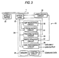
- Fig. 3 is a block diagram for schematically indicating an arrangement of a data recording and readingout apparatus 20 which is employed so as to record data on the optical recording medium 1, and to readout data from the optical recording medium 1.
- the recording layer 7 is heated at the temperature higher than, or equal to the decomposition temperature of the platinum oxide in the above-explained manner, and then, the platinum oxide which has been contained as the major component in the recording layer 7 is decomposed into both platinum and oxygen.
Abstract
Description
- The present invention is related to a data recording and readingout system which records data on an optical recording medium, and readout data from the optical medium. More precisely speaking, the present invention is directed to such a data recording and readingout system capable of largely increasing a recording capacity of the optical recording medium
- Conventionally, optical recording media typically known as CDs and DVDs have been widely used as recording media employed so as to record thereon digital data. Very recently, such optical recording media having larger storage capacities and higher data transfer rates have been actively developed.
- In the above-described optical recording media, wavelengths "λ" of laser beams which are employed so as to record and readout data are shortened and numerical apertures "NA" of objective lenses are increased so as to narrow diameters of laser beam spots, so that recording capacities of the optical recording media may be increased (refer to, for instance, Japanese Patent Publication JP-A-8-235638).
- In an optical recording medium, if lengths of recorded marks recorded on the optical recording medium and a length between the adjoining recorded marks, namely, a length of a region where a recorded mark is not formed (will be referred to as "blank region" hereinafter) becomes smaller than a limit of resolution, then data cannot be readout from this optical recording medium.
- A beam spot diameter of a laser beam is determined based upon a wavelength "λ" of the laser beam and a numerical aperture "NA" of an objective lens used to converge the laser beam, and thus, becomes "λ/NA" At this time, in such a case that a repetition frequency between a recorded mark and a blank region, namely, a spatial frequency becomes larger than, or equal to λ/2NA, both the recorded mark and data recorded on the blank region cannot be readout.
- As a consequence, a length of a recorded mark and a length of a blank region which correspond to a readable spatial frequency become larger than, or equal to "λ/4NA", respectively, and when the laser beam having the wavelength "λ" is collected onto a surface of an optical recording medium by the objective lens having the numerical aperture "NA", both the recorded mark having the length of "λ/4NA" and the blank region having the length of "λ/4NA" may constitute both the shortest recorded mark and the shortest blank region, which can be read.
- As previously explained, in the case that data is readout, there is a limit of resolution capable of readingout data, and also, there are certain limitations in a length of a recorded mark and a length of a blank region under which the data can be readout.
- Accordingly, even when both small recorded marks and small blank regions are formed and data could be recorded, the recorded data cannot be readout. As a result, both the lengths of the recorded marks and the lengths of the blank regions which can be formed when the data are recorded on the optical recording media are necessarily limited, so that the recording capacities of the optical recording media can be very hardly increased.
- As a consequence, an object of the present invention is to provide a data recording and readingout system capable of largely increasing a recording capacity of data onto an optical recording medium.
- The above-described object of the present invention may be achieved by such a data recording and readingout system in which data is recorded and readout, or is readout, on or from an optical recording medium by irradiating a laser beam having a wavelength "λ" via an objective lens of a numerical aperture "NA" onto the optical recording medium, wherein: while the optical recording medium contains a layered structure formed by sandwiching at least a dielectric layer between a recording layer and an optical absorption layer, with respect to the optical recording medium arranged in such a manner that data recorded by a recorded mark train can be readout and the recorded mark train contains a recorded mark smaller than, or equal to a limit of resolution, the laser beam is irradiated via the objective lens and a solid immersion lens having a refractive index "n" which is positioned between the optical recording medium and the objective lens, so that the data is recorded and readout, or is readout with respect to the optical recording medium by a recorded mark train which contains a recorded mark smaller than, equal to "λ/(4·n2·NA)."
- In the present invention, when the data recorded on the optical recording medium is readout, the data recording and readingout system has been arranged in such a manner that the laser beam having the wavelength "λ" is irradiated onto the optical recording medium via both the objective lens of the numerical number "NA" and the solid immersion lens having the refractive index "n." In such a case that the laser beam is irradiated onto the optical medium in the above-described manner, a spot diameter of the laser beam can be made small, and the limit of resolution can be decreased from "λ/4NA" to "λ/(4·n2·NA)." As a result, such a data which has been constituted by the smaller recorded mark train can be readout, as compared with such a case that the laser beam is irradiated via only the objective lens so as to readout the data.
- In addition, in the present invention, the optical recording medium has been constituted by containing the layered structure formed by sandwiching at least the dielectric layer between the recording layer and the optical absorption layer. In the case that the optical recording medium has such a structure, even if the lengths of the recorded marks which constitute the recorded mark train and the lengths of the blank regions between the adjoining recorded marks are shorter than, or equal to the limit of restriction, the data can be readout from the optical recording medium.
- As previously explained, in accordance with the present invention, the limit of resolution is decreased from "λ/4NA" to "λ/(4·n2·NA)", and in addition, such a data can be readout which has been constituted by the recorded mark train having the length which is shorter than, or equal to this decreased limit of resolution "λ/(4·n2·NA)." As a consequence, such a recorded mark train having a very short length which is shorter than, or equal to "λ/(4·n2·NA)" may be formed in order that the data can be recorded. As a consequence, the recording capacity of the optical recording medium can be largely increased.
- In the present invention, the recording layer is preferably constituted in such a manner that when a laser beam which has been set to recording power is irradiated onto the recording layer, a volume change occurs in such a region that the laser beam is irradiated. Since the region where the volume of the recording layer has been changed owns an optical characteristic different from that of the region where the volume of the recording layer is not changed, the first-mentioned region may be utilized as the recorded mark.
- The recording layer may be formed by containing a noble metal oxide, or a noble metal nitride as the major component.
- In this specification, such an expression that a certain layer contains an element as a major component implies such a fact that a containing ratio of this element becomes the largest containing ratio among those of elements contained in this layer.
- In the present invention, in such a case that the recording layer contains the noble metal oxide as the major component, it is preferable to irradiate the laser beam onto the optical recording medium so as to decompose the noble metal oxide into both a noble metal and oxygen, and to form bubble pit. Then, since very fine particles of the noble metal are dispersed inside the bubble pit, a recorded mark is formed, so that data may be recorded.
- In the present invention, in such a case that the recording layer contains the noble metal oxide as the major component, it is preferable to employ a platinum oxide as the noble metal oxide.
- The decomposition temperature of the platinum oxide is high, as compared with the decomposition temperatures of other noble metal oxides. As a consequence, when the laser beam which has been set to the recording power is irradiated so as to form the recorded mark, even in such a case that the heat is diffused from the region to which the laser beam has been irradiated to the peripheral portion thereof, it is possible to avoid that the decomposition reaction of the platinum oxide occurs in such a region other than the region to which the laser beam has been irradiated. As a consequence, the volume of the desirable region of the recording layer is changed, so that the recorded mark can be formed.
- Also, in the case that a laser beam having high readout power is irradiated so as to readout data, since the decomposition temperature of the platinum oxide is high, as compared with the decomposition temperatures of other noble metal oxides, there is no risk that the platinum oxide is decomposed into both platinum and oxygen. As a consequence, even when the data recorded on the optical recording medium is readout in a repetition manner, there are no such risks that the shape of the recorded mark is changed, and also, the volume change is newly produced in the region other than the region where the recorded mark has been formed. As a result, the durability as to the readingout operation of the optical recording medium can be improved.
- In the present invention, in such a case that the recording layer contains the noble metal nitride as the major component, it is preferable to employ a platinum nitride as the noble metal nitride which is employed so as to form the recording layer.
- In the present invention, it is preferable to construct both a dielectric layer and an optical absorption layer in such a manner that both the dielectric layer and the optical absorption layer are deformed in connection with the volume change of the recording layer when a recorded mark train is formed on the recording layer.
- An optical characteristic of such a region that both the dielectric layer and the optical absorption layer have been deformed is made different from an optical characteristic of such a region that both the dielectric layer and the optical absorption layer are not deformed. As a result, such a reproduction signal having a better signal characteristic can be obtained.
- In accordance with the present invention, it is possible to provide the data recording and readingout system capable of largely increasing the recording capacity of the optical recording medium.
-
- Fig. 1 is a perspective view for schematically showing an optical recording medium according to a preferred embodiment mode of the present invention;
- Fig. 2 is a sectional view for indicating an enlarged portion of the optical recording medium, which is indicated by symbol "A" of Fig. 1;
- Fig. 3 is a block diagram for schematically representing an arrangement of a data recording and readingout apparatus according to a preferred embodiment mode of the present invention;
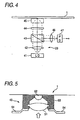
- Fig. 4 is a block diagram for schematically showing a structure of an optical head;
- Fig. 5 is a sectional view for schematically indicating a structure of a lens unit;
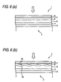
- Fig. 6(a) is a sectional view for showing a partially enlarged portion of the optical recording medium before data is recorded; and
- Fig. 6(b) is a sectional view for showing the partially enlarged portion of the optical recording medium after data has been recorded.
- Referring now to the accompanying drawings, preferred embodiment modes of the present invention will be described in detail.
Fig. 1 is a perspective view for schematically showing an optical recording medium I according to a preferred embodiment mode of the present invention. Fig. 2 is a sectional view for showing an enlarged portion of the optical recording medium of Fig. 1, which is indicated by symbol "A." - As indicated in Fig. 2, the
optical recording medium 1 according to this embodiment mode is provided with a supportingsubstrate 1. Areflection layer 3, a thirddielectric layer 4, anoptical absorption layer 5, a seconddielectric layer 6, a recording layer 7, and a firstdielectric layer 8 have been layered on the supportingsubstrate 2 in this order. - In this embodiment mode, the
optical recording medium 1 has been constituted in such a manner that since a laser beam is irradiated from an arrow direction shown in Fig. 2, data is recorded and the recorded data is readout. - The supporting
substrate 2 functions as a supporting member used to secure a mechanical strength which is required for theoptical recording medium 1. - As a material used to form the supporting
substrate 2, if a material can function as the supporting member of theoptical recording medium 1, then there is no specific limitation. The supportingsubstrate 2 may be formed by, for example, glass, ceramics, a resin, and the like. Among these forming materials, a polycarbonate resin and an olefin resin are especially preferable in view of processing characteristics, optical characteristics, and the like. - In this embodiment mode, the supporting
substrate 2 has been formed by employing the polycarbonate resin, and has a thickness of approximately 1.1 mm. - Also, both grooves and lands (not shown) have been alternately formed on the surface of the supporting
substrate 2. The grooves and/or the lands which have been formed on the surface of the supportingsubstrate 2 may function as guide tracks of a laser beam in the case that data is recorded and data is readout. - The
reflection layer 3 may play such a role that thisreflection layer 3 reflects a laser beam entered from the side of the firstdielectric layer 8, and again projects the reflected laser beam from the firstdielectric layer 8. - As to a material for forming the
reflection layer 3, if any material can reflect a laser beam, then there is no specific restriction. Thereflection layer 3 may be formed by employing at least one sort of such an element which is selected from a group consisted of Mg, Al, Ti, Cr, Fe, Co, Ni, Cu, Zn, Ge, Pt, Au, Ag, Pd, Nd, In, Sn, and Bi. - Although there is no specific limitation in a thickness of the
reflection layer 3, it is preferable that thereflection layer 3 may have a thickness from 5 nm to 200 nm. - The third
dielectric layer 4 owns a function capable of protecting both the supportingsubstrate 2 and thereflection layer 3, and also owns another function capable of physically and chemically protecting theoptical absorption layer 5 which is formed on this thirddielectric layer 4. - As to a dielectric material used to form the third
dielectric layer 4, there is no specific limitation. The thirddielectric layer 4 may be formed by using, for example, an oxide, a sulfide, a nitride, or a dielectric material made by combining these oxide, sulfide, and nitride with each other. The thirddielectric layer 4 is preferably formed by an oxide, a nitride, a sulfide, a fluoride, or a composite material made of these oxide, nitride, sulfide, and fluoride, which contain at least one sort of metal selected from a group consisted of Si, Zn, Al, Ta, Ti, Co, Zr, Pb, Ag, Sn, Ca, Ce, V, Cu, Fe, Mg. - The third
dielectric layer 4 may be formed on the surface of thereflection layer 3 by performing a physical vapor deposition method with employment of a chemical seed containing, for example, the structural element of the thirddielectric layer 4. As the physical vapor deposition method, a vapor deposition method, a sputtering method, and the like may be employed. - Although a thickness of the third
dielectric layer 4 is not specifically limited, such thicknesses defined from 10 nm to 140 nm may be preferably employed. - The
optical absorption layer 5 owns such a function that when a laser beam whose power has been set to recording power is irradiated to theoptical recording medium 1, theoptical absorption layer 5 absorbs the irradiated laser beam to generate heat, and transfers the generated heat to the recording layer 7. - In this embodiment mode, the
optical absorption layer 5 has been formed by an alloy which owns a high optical absorbing coefficient and a low thermal conductivity, and also, contains at least one of Sb and Te. - As the above-explained alloy containing at least any one of Sb and Te which are contained in the
optical absorption layer 5, such an alloy is more preferable which owns a composition expressed by either (SbaTe1-a) 1-bMb, or {(GeTe) c(Sb2Te3) 1-c}dX1-d. In this composition, the element "M" indicates an element except for Sb and Te, and the element "X" indicates an element except for Sb, Te, and Ge. - When the alloy containing at least any one of Sb and Te which are contained in the
optical absorption layer 5 owns a composition which is expressed by (SbaTe1-a)1-bMb, symbols "a" and "b" are preferably equal to 0≤a≤1 and 0≤b≤0.25. When symbol "b" has exceeded 0.25, there is a risk that an optical absorption coefficient may become lower than the value required for theoptical absorption layer 5. Also, there is another risk that a thermal conductivity may become lower than the value required for theoptical absorption layer 5. - Although the element "M" is not especially limited, this element "M" may preferably contain as a major component at least one sort of such an element which is selected from a group consisted of In, Ag, Au, Bi, Se, Al, Ge, P, H, Si, C, V, W, Ta, Zn, Mn, Ti, Sn, Pb, Pd, N, O, and a rare earth element (Sc, Y and lanthanoid).
- On the other hand, when the alloy containing at least any one of Sb and Te which are contained in the
optical absorption layer 5 owns a composition which is expressed by {(GcTc)c(Sb2Te3)1-c}dX1-d, symbols "c" and "d" are preferably equal to 1/3≤c≤2/3 and 0.9≤d. - Although the element "X" is not especially limited, this element "M" may preferably contain as a major component at least one sort of such an element which is selected from a group consisted of In, Ag, Au, Bi, Se, A1, P, H, Si, C, V, W, Ta, Zn, Mn, Ti, Sn, Pb, Pd, N, O, and a rare earth element.
- The
optical absorption layer 5 may be formed on the surface of the thirddielectric layer 4 by a physical vapor deposition method using a chemical element which contains the structural element of theoptical absorption layer 5. As the physical vapor deposition method, a vapor deposition method, a sputtering method, and the like may be employed. - The
optical absorption layer 5 may preferably own a thickness defined from 5 nm to 100 nm. In the case that a thickness of theoptical absorption layer 5 is smaller than 5 nm, the optical absorption ratio becomes excessively low. On the other hand, if a thickness of theoptical absorption layer 5 exceeds 100 nm, as will be discussed later, then there is a risk that theoptical absorption layer 5 can be hardly deformed when a bubble pit is formed in the recording layer 7. - The
second dielectric layer 6 owns such a function capable of physically and chemically protecting the recording layer 7 in combination with the first dielectric layer 8 (will be discussed later). - Although there is no specific limitation in a material used to form the
second dielectric layer 6, this seconddielectric layer 6 may be formed by employing a material similar to that of the thirdelectric layer 4. Also, similar to the thirddielectric layer 4, thesecond dielectric layer 6 may be formed by a physical vapor deposition method with employment of a chemical seed containing the structural element of thesecond dielectric layer 6, - The
second dielectric layer 6 is preferably formed in such a manner that this seconddielectric layer 6 owns a thickness defined from 5 nm to 100 nm. - The recording layer 7 corresponds to such a layer on which data is recorded. When data is recorded, a recorded mark is formed on the recording layer 7.
- In this embodiment mode, the recording layer 7 contains a platinum oxide "PtOx" as a major component.
- In this embodiment mode, in order that a reproduction signal having a high C/N ratio is obtained even in such a case that a length of a recorded mark and a length of a blank region between the adjoining recorded marks are smaller than limits of resolution, symbol "x" of "PtOx" is preferably equal to or larger than 1.0 but less than 3.0 (i.e. 1.0 ≤x<3.0).
- The recording layer 7 may be formed on the surface of the
second dielectric layer 6 by performing a physical vapor deposition method with employment of a chemical seed containing, for example, the structural element of the recording layer 7 as the major component. As the physical vapor deposition method, a vapor deposition method, a sputtering method, and the like may be employed. - A thickness of the recording layer 7 is preferably equal to 2 nm to 20 nm, and more preferably equal to 4 nm to 20 nm. When a thickness of the recording layer 7 is smaller than 2 nm, there is a risk that the recording layer 7 cannot be formed as a continuous film, whereas when a thickness of the recording layer 7 exceeds 20 nm, there is another risk that the recording layer 7 can be hardly deformed, and a recording sensitivity thereof may be lowered.
- The first
dielectric layer 8 owns such a function capable of physically and chemically protecting the recording layer 7. - Although the material used to form the first
dielectric layer 8 is not specifically limited, the firstdielectric layer 8 may be formed by employing a material similar to that of the thirddielectric layer 4. Also, similar to the thirddielectric layer 4, the firstdielectric layer 8 may be formed by performing a physical vapor deposition method with employment of a chemical seed containing the structural element of the firstdielectric layer 8. - Fig. 3 is a block diagram for schematically indicating an arrangement of a data recording and
readingout apparatus 20 which is employed so as to record data on theoptical recording medium 1, and to readout data from theoptical recording medium 1. - As indicated in Fig. 3, the data recording and
readingout apparatus 20, according to this embodiment mode, has been equipped with aspindle motor 22, anoptical head 23, acontroller 24, and alaser driving circuit 25. Thespindle motor 22 rotates theoptical recording medium 1. Theoptical head 23 emits a laser beam toward theoptical recording medium 1, and detects a laser beam reflected by theoptical recording medium 1. Thecontroller 24 controls both the operation of thespindle motor 22 and the operation of theoptical head 23, and also, performs a predetermined signal process operation with respect to either externally inputted data or data readout from theoptical recording medium 1. Thelaser driving circuit 25 supplies a laser drive signal to theoptical head 23. - As indicated in Fig. 3, the
controller 24 has been equipped with afocus servo circuit 31, agap measuring circuit 32, a trackingservo circuit 33, acontrol circuit 34, amemory 35, adata processing circuit 36, and awrite strategy circuit 37. Thefocus servo circuit 31 produces a focus control signal in response to a focus error signal read out from theoptical recording medium 1. Thegap measuring circuit 22 measures a distance between theoptical recording medium 1 and theoptical head 23. The trackingservo circuit 33 produces a tracking control signal in response to a tracking error signal read out from theoptical recording medium 1. Thecontrol circuit 34 controls an entire operation of thecontroller 24. - The
memory 35 is constituted by a DRAM, an SRAM, or a flash memory, or the like. Thememory 35 stores thereinto program data which is used to control the entire operation of the data recording andreadingout apparatus 20, and stores thereinto various sorts of data which are employed in process operations executed in thecontroller 24. - The
control circuit 34 is employed so as to control entire operations of thecontroller 24, and outputs control signals to the respective internal circuits of the data recording andreadingout apparatus 20 in response to a key input by user, or command data corresponding to a button input. - The
data processing circuit 36 functions as an encoder and a decoder. When data is recorded on theoptical recording medium 1, the encoder performs an encoding process operation with respect to user data which is externally inputted by a user. When data is readout from theoptical recording medium 1, the decoder executes a decoding process operation with respect to a reproduction signal readout from theoptical recording medium 1. - The
write strategy circuit 37 produces a laser power control signal used to modulate power of a laser beam based upon the data which has been encoding-processed by thedata processing circuit 36. - Fig. 4 is a block diagram for schematically indicating a structure of the
optical head 23. - As indicated in Fig. 4, the
optical head 23 has been provided with alaser diode 41 for emitting a laser beam, acollimator lens 42, apolarizing beam splitter 43, a 1/4wavelength plate 44, alens unit 45, acollective lens 46, and aphotodetector 47. Thecollimator lens 42 converts the laser beam emitted from thelaser diode 41 into collimated light. Thepolarizing beam splitter 43 transmits the laser beam which is entered via thecollimator lens 42, and on the other hand, reflects a laser beam which is reflected by theoptical recording medium 1 to conduct the reflected laser beam to thephotodetector 47. The 1/4wavelength plate 44 converts a linearly polarized laser beam which is entered from thepolarizing beam splitter 43 into a circularly polarized laser beam. Thelens unit 45 converges a laser beam which is entered via the 1/4wavelength plate 44 to emit the converged laser beam to theoptical recording medium 1. Thecollective lens 46 collects laser beams which are entered via thepolarizing beam splitter 43. Thephotodetector 47 detects a strength of the laser beam collected by thecollective lens 46. - Fig. 5 is a sectional view for schematically indicating a structure of the
lens unit 45. - As indicated in Fig. 5, the
lens unit 45 has been provided with anobjective lens 51, a solid immersion lens (SIL) 52, ahead slider 53, and asuspension 54. Thesolid immersion lens 52 is arranged between theobjective lens 51 and a light incident plane of theoptical recording medium 1. Thehead slider 53 holds both theobjective lens 51 and thesolid immersion lens 52. Thesuspension 54 has been suspended on thehead slider 53. - The
objective lens 51 corresponds to such a lens which converges a laser beam entered via the 1/4wavelength plate 44, and enters the converged laser beam to thesolid immersion lens 52. Both a plane on the light incident side and another plane on the light projection side have been constituted by spherical planes. Although a numerical aperture "NA" of theobjective lens 51 is not specifically limited, thisobjective lens 51 owns such a numerical aperture "NA" defined from 0.4 to 0.6. - The
solid immersion lens 52 corresponds to such a lens which further converges the laser beam which has been converged by theobjective lens 51. In thissolid immersion lens 52, a plane on the light incident side has been constructed of a spherical plane, whereas a plane on the light projection side has been constructed of a flat plane. Also, thesolid immersion lens 52 owns a refractive index "n" defined from 1.5 to 2.5, and has such a higher refractive index than a refractive index "n0 (n0=1)" within air. In such a case that a laser beam is irradiated via thissolid immersion lens 52 onto theoptical recording medium 1, a spot diameter of the laser beam becomes λ/(n2·NA), and therefore, the beam spot diameter can be made smaller, as compared with another beam spot diameter "λ/NA" in the case that the laser beam is irradiated only via theobjective lens 51 onto theoptical recording medium 1. In this case, symbols "λ", "n", and "NA" represent a wavelength of the laser beam, a refractive index of thesolid immersion lens 52, and a numerical aperture of theobjective lens 51, respectively. - The
head slider 53 is employed so as to support both theobjective lens 51 and thesolid immersion lens 52, and has been constituted in such a manner that thehead slider 53 may obtain floating force due to an air stream which is produced when theoptical recording medium 1 is rotated, and thus, may float theobjective lens 51 and thesolid immersion lens 52. - Also, while a portion of a bottom plane of the
head slider 53 is constituted by a conductor, thishead slider 53 may constitute one sort of a capacitor with respect to theoptical recording medium 1. As a result, in the case that a distance between the bottom plane of thehead slider 53 and the surface of theoptical recording medium 1 is changed, the capacitance of the above-explained capacitor is changed. As a consequence, since this change of the capacitance is measured by the above-describedgap measuring circuit 32, a distance of a gap between the surface of thesolid immersion lens 52 and the surface of theoptical recording medium 1 may be measured. - The
suspension 54 is employed in order to support thehead slider 53 and also to adjust the distance between thehead slider 53 and the surface of theoptical recording medium 1. The elastical characteristic of thesuspension 54 has been adjusted in such a manner that when thehead slider 53 is floated, the distance between thehead slider 53 and the surface of the optical recording medium I may become approximately 50 nm to 100 nm. - The data recording and
readingout apparatus 20 having the above-explained arrangement records data on theoptical recording medium 1 in the below-mentioned manner. - When the
optical recording medium 1 is firstly set on the data recording andreadingout apparatus 20, thecontroller 24 drives thespindle motor 22 so as to rotate theoptical recording medium 1. When theoptical recording medium 1 is rotated, theoptical head 23 may receive floating force to be floated, and is traveled, while the distance between thisoptical head 23 and the surface of theoptical recording medium 1 is maintained from approximately 50 nm to 100 nm. - Next, the
controller 24 outputs a laser drive signal via thelaser driving circuit 25 to theoptical head 23 in order to emit such a laser beam having readout power from thelaser diode 41. The emitted laser beam is converted into collimated laser light by thecollimator lens 42, and thereafter, this collimated laser beam passes through thepolarizing beam splitter 43 and then, is irradiated via both the I/4wavelength 44 and thelens unit 45 onto theoptical recording medium 1. - As a result, the laser beam is reflected by the
optical recording medium 1, and then, the reflected laser beams are entered to both a tracking control-purpose photodetector and a focus control-purpose photodetector (not shown). Subsequently, a predetermined calculating process operation is carried out with respect to the detection signals outputted from the photodetectors, so that both a tracking error signal and a focus error signal are produced so as to be outputted to both thefocus servo circuit 31 and the trackingservo circuit 33. - Also, at this time, the distance between the surface of the
solid immersion lens 52 and the surface of theoptical recording medium 1 is measured by thegap measuring circuit 32, and then, the measured distance signal is outputted to thefocus servo circuit 31. - The tracking
servo circuit 33 produces a tracking control signal based upon the tracking error signal, and thefocus servo circuit 31 produces a focus control signal based upon the gap signal outputted from thegap measuring circuit 32 and the focus error signal. The trackingservo circuit 33 outputs the tracking control signal and thefocus servo circuit 31 outputs the focus control signal to theoptical head 23. - As a result, the position of the
optical head 23 is controlled in order that the laser beam automatically follows the tracks of theoptical recording medium 1, and further, the floating amount of theoptical head 23 is fine-adjusted in order that the laser beam is focused onto theoptical recording medium 1. - Next, user data is entered to the data recording and
readingout apparatus 20, and then, thedata processing circuit 36 applies error correction-purpose parity data to the entered user data, and performs a predetermined coding processing operation with respect to the resultant user data so as to be coded. - The data which has been coded is outputted to the
write strategy circuit 37, and thewrite strategy circuit 37 produces a laser power control signal based upon the data which has been coded, while the laser power control signal is used in order to modulate a laser beam outputted from thelaser diode 41. - The laser power control signal produced by the
write strategy circuit 37 is outputted to thelaser driving circuit 25, and thus, thelaser driving circuit 25 modulates power of the laser beam emitted from theoptical head 23 to produce a recording-purpose laser beam having the modulated power which is irradiated to theoptical recording medium 1. - Fig. 6(a) is a sectional view for showing a partially enlarged portion of the
optical recording medium 1 before data is recorded. Fig. 6(b) is a sectional view for showing the partially enlarged portion of theoptical recording medium 1 after data has been recorded. - When the laser beam which has been modulated by the recording-purpose power is irradiated onto the
optical recording medium 1, a region of theoptical absorption layer 5 where the laser beam is irradiated is heated. The heat produced in theoptical absorption layer 5 is transferred to the recording layer 7, so that the temperature of the recording layer 7 is increased. - As to the platinum oxide which is contained as the major component in the recording layer 7, since the transmission characteristic thereof with respect to a laser beam is high, even if the laser beam is irradiated onto the recording layer 7, this recording layer 7 itself can be hardly heated, and also, it is practically difficult that the temperature of the recording layer 7 is increased higher than, or equal to the decomposition temperature of the platinum oxide. However, in this embodiment mode, since the
optical absorption layer 5 has been provided, thisoptical absorption layer 5 is heated, and then, the heat produced by theoptical absorption layer 5 is transferred to the recording layer 7, so that the temperature of the recording layer 7 is increased. - The recording layer 7 is heated at the temperature higher than, or equal to the decomposition temperature of the platinum oxide in the above-explained manner, and then, the platinum oxide which has been contained as the major component in the recording layer 7 is decomposed into both platinum and oxygen.
- As a result, an shown in Fig. 6(b), the platinum oxide is decomposed, a
bubble pit 7a is formed in the recording layer 7 by produced oxygen gas, and then, veryfine particles 7b made of platinum are dispersed into thebubble pit 7a. - At the same time, as indicated in Fig. 6(b), the recording layer 7 is deformed in combination with both the
optical absorption layer 5 and thesecond dielectric layer 6 by pressure of the produced oxygen gas. - Such a region in which the
bubble pit 7a is formed in the above-described manner, and also, theoptical absorption layer 5, thesecond dielectric layer 6, and the recording layer 7 have been deformed owns such an optical characteristic from that of other regions. As a result, a recorded mark may be formed by the region in which thebubble pit 7a is formed, and also, theoptical absorption layer 5, thesecond dielectric layer 6, and the recording layer 7 are deformed. - Among the recorded marks and the blank regions between the adjoining recorded marks, such recorded marks and blank regions are involved, the lengths of which are shorter than the limits of resolution, and a recorded mark train whose length is shorter than the limit of resolution is formed.
- In this embodiment mode, since the recording layer 7 contains the platinum oxide whose decomposition temperature is high as the major component, when the laser beam which has been set to the recording-purpose power is irradiated so as to form the recorded mark, even in such a case that the heat is diffused from the region to which the laser beam has been irradiated to the recording layer 7 located at the peripheral portion thereof it is possible to avoid that the decomposition reaction of the platinum oxide occurs in such a region other than the region to which the laser beam has been irradiated. As a consequence, the
bubble pit 7a is formed in the desirable region of the recording layer 7, so that the recorded mark can be formed. - On the other hand, the data which has been recorded on the
optical recording medium 1 is readout by the data recording andreadingout apparatus 20 in the below-mentioned readingout manner. - When the
optical recording medium 1 is set on the data recording andreadingout apparatus 20, first of all, both a focus control operation and a tracking control operation are carried out by thecontroller 24, and further, address data is produced by thecontroller 24. - Next, the
controller 24 moves theoptical head 23 to such an address at which data to be readout has been recorded, and irradiates a laser beam emitted from theoptical head 23 via theobjective lens 51 and thesolid immersion lens 52 onto the recorded mark train which has been formed on theoptical recording medium 1. - Thereafter, the laser beam is reflected by the
optical recording medium 1, and then, this reflected laser beam is entered via thesolid immersion lens 52, theobjective lens 51, the 1/4wavelength plate 44, thepolarization beam splitter 43, and thecollective lens 46 to thephotodetector 47. A strength of the laser beam is detected by thephotodetector 47 in the above-explained manner, so that a reproduction signal is produced. - In this embodiment mode, since the data recording and readingout apparatus has been arranged in such a manner that the laser beam is irradiated via the
objective lens 51 and thesolid immersion lens 52 to theoptical recording medium 1, the spot diameter of the laser beam can be made small, and the limit of resolution can be decreased from "λ/4NA" to "λ/(4·n2·NA)." As a result, such a data which has been constituted by the smaller recorded mark train can be readout, as compared with such a case that the laser beam is irradiated via only theobjective lens 51 so as to readout the data. - In addition, in this embodiment mode, as shown in Fig. 6(b), the
bubble pit 7a has been formed in the recording layer 7, and the veryfine particles 7b made of platinum have been dispersed inside thebubble pit 7a, so that the recorded marks have been formed to record the data. In such a case that even if the lengths of the recorded marks which constitute the recorded mark train and the lengths of the blank regions between the adjoining recorded marks are shorter than, or equal to the limit of restriction, the data can be readout. - As previously explained, in accordance with this embodiment mode, the resolution limit is decreased from "λ/4NA" to "λ/(4·n2·NA)", and in addition, such a data can be readout which has been constituted by the recorded mark train having the length which is shorter than, or equal to this decreased limit of resolution "λ/(4·n2·NA)." As a consequence, such a recorded mark train having a very short length which is shorter than, or equal to "λ/(4·n2·NA)" may be formed in order that the data can be recorded. As a consequence, the recording capacity of the optical recording medium can be largely increased.
- A reproduction signal which has been produced by the
photodetector 47 is processed by executing both a waveform shaping process operation and a Viterbi decoding process operation, and then, the processed reproduction signal is outputted to thedata processing circuit 36. Thus, thisdata processing circuit 36 performs both an error correcting process operation and a decoding process operation with respect to the supplied reproduction signal. - The user data may be readout in the above-described manner, and then, the readout user data may be outputted to the external unit, or may be stored in the
memory 35 as reproduction data. - The present invention is not limited only to the above-described embodiment mode, but may be freely modified within the technical scope defined in Claims for a patent. Apparently, these modifications may be involved in the technical scope of the present invention.
- For instance, in the
optical recording medium 1 shown in Fig. 1 and Fig. 2, the recording layer 7, thesecond dielectric layer 6, and theoptical absorption layer 5 have been sequentially stacked from the light incident plane of the laser beam. The present invention is not limited only to this stacked structure, but may be freely modified. For example, the recording layer 7, thesecond dielectric layer 6, and theoptical absorption layer 5 may be alternatively stacked from the opposite side of the light incident plane of the laser beam. Otherwise, an optical absorption layer, a dielectric layer, a recording layer, another dielectric layer, and another optical absorption layer may be sequentially stacked. In other words, in accordance with the present invention, an optical recording medium may merely contain a layered structure which has been formed by sandwiching at least a dielectric layer between a recording layer and an optical absorption layer.
Claims (8)
- A data recording and readingout system in which data is recorded and readout or is readout, on or from an optical recording medium by irradiating a laser beam having a wavelength "λ" via an objective lens of a numerical aperture "NA" onto said optical recording medium,
the optical recording medium containing a layered structure formed by placing at least a dielectric layer between a recording layer and an optical absorption layer, with respect to said optical recording medium arranged in such a manner that data recorded by a recorded mark train can be readout and said recorded mark train contains a recorded mark smaller than, or equal to a limit of resolution,
said laser beam irradiated via said objective lens and a solid immersion lens having a refractive index "n" which is positioned between said optical recording medium and said objective lens, so that the data is recorded and readout, or is readout with respect to said optical recording medium by a recorded mark train which contains a recorded mark smaller than, equal to "λ/(4·n2·NA)." - A data recording and readingout system as claimed in claim 1, wherein said recording layer of said optical recording medium contains a noble metal oxide as a major component.
- A data recording and readingout system as claimed in claim 2, wherein said noble metal oxide contained as the major component in said recording layer is constructed of a platinum oxide; and when said laser beam is irradiated onto said platinum oxide, said platinum oxide is decomposed into both platinum and oxygen.
- A data recording and readingout system as claimed in claim 1, wherein both said dielectric layer and said optical absorption layer have been constituted in such a manner that said dielectric layer and said optical absorption layer are deformed in connection with a volume change of said recording layer when said recorded mark train is formed on the recording layer.
- A data recording and readingout apparatus which records data on a optical recording medium and readout data from the optical recording medium, comprising:a light source which irradiates a laser beam having a wavelength "λ";an objective lens of a numerical aperture "NA" defined from 0.4 to 0.6; anda solid immersion lens having a refractive index "n" defined from 1.5 to 2.5, which is positioned between said optical recording medium and said objective lens,wherein the optical recording medium contains a layered structure formed by placing at least a dielectric layer between a recording layer and an optical absorption layer, on which a recorded mark train which contains a recorded mark smaller than, equal to "λ/(4·n2·NA)" is formed.
- A data recording and readingout system as claimed in claim 5, wherein said recording layer of said optical recording medium contains a noble metal oxide as a major component.
- A data recording and readingout system as claimed in claim 6, wherein said noble metal oxide contained as the major component in said recording layer is constructed of a platinum oxide; and when said laser beam is irradiated onto said platinum oxide, said platinum oxide is decomposed into both platinum and oxygen.
- A data recording and readingout system as claimed in claim 5, wherein both said dielectric layer and said optical absorption layer have been constituted in such a manner that said dielectric layer and said optical absorption layer are deformed in connection with a volume change of said recording layer when said recorded mark train is formed on the recording layer.
Applications Claiming Priority (1)
| Application Number | Priority Date | Filing Date | Title |
|---|---|---|---|
| JP2004256764A JP2006073120A (en) | 2004-09-03 | 2004-09-03 | Data recording and reproducing system |
Publications (2)
| Publication Number | Publication Date |
|---|---|
| EP1632937A2 true EP1632937A2 (en) | 2006-03-08 |
| EP1632937A3 EP1632937A3 (en) | 2008-01-23 |
Family
ID=35507062
Family Applications (1)
| Application Number | Title | Priority Date | Filing Date |
|---|---|---|---|
| EP05019117A Withdrawn EP1632937A3 (en) | 2004-09-03 | 2005-09-02 | Data recording and readingout system |
Country Status (3)
| Country | Link |
|---|---|
| US (1) | US7554894B2 (en) |
| EP (1) | EP1632937A3 (en) |
| JP (1) | JP2006073120A (en) |
Families Citing this family (8)
| Publication number | Priority date | Publication date | Assignee | Title |
|---|---|---|---|---|
| JP2005022196A (en) * | 2003-07-01 | 2005-01-27 | Tdk Corp | Optical recording disc |
| JP2005025842A (en) * | 2003-07-01 | 2005-01-27 | Tdk Corp | Optical recording disk |
| JP2005025841A (en) * | 2003-07-01 | 2005-01-27 | Tdk Corp | Optical recording disk |
| JP2005044438A (en) * | 2003-07-22 | 2005-02-17 | Tdk Corp | Optical recording disk |
| JP2005129181A (en) * | 2003-10-27 | 2005-05-19 | National Institute Of Advanced Industrial & Technology | Optical recording disk |
| US20090154319A1 (en) * | 2006-05-15 | 2009-06-18 | Koninklijke Philips Electronics N.V. | Optical disc reading apparatus and method therefore |
| JP2008016696A (en) * | 2006-07-07 | 2008-01-24 | Tdk Corp | Method of inspecting dustproof performance of photo detector and method of manufacturing photo detector using the same |
| JP4345859B2 (en) * | 2007-09-12 | 2009-10-14 | ソニー株式会社 | Optical pickup device, optical recording / reproducing device, and gap control method |
Citations (6)
| Publication number | Priority date | Publication date | Assignee | Title |
|---|---|---|---|---|
| US6181478B1 (en) * | 1999-07-16 | 2001-01-30 | Michael Mandella | Ellipsoidal solid immersion lens |
| JP2004220687A (en) * | 2003-01-14 | 2004-08-05 | Samsung Japan Corp | Recording medium of superresolution near field structure, recording method and reproducing method thereof, recording apparatus and reproducing apparatus of the same |
| US20050105418A1 (en) * | 2003-10-31 | 2005-05-19 | National Institute Of Advanced Industrial Science And Technology | Method for determining a reproducing power of a laser beam and an apparatus for recording and reproducing data |
| EP1555666A1 (en) * | 2002-06-24 | 2005-07-20 | TDK Corporation | Optical recording/reproducing method and optical recording medium |
| US20050169157A1 (en) * | 2003-10-28 | 2005-08-04 | Tdk Corporation | Optical recording disk |
| US20050219994A1 (en) * | 2004-03-29 | 2005-10-06 | Tdk Corporation | Optical recording medium |
Family Cites Families (3)
| Publication number | Priority date | Publication date | Assignee | Title |
|---|---|---|---|---|
| JP3241560B2 (en) | 1995-02-24 | 2001-12-25 | ソニー株式会社 | Optical recording medium and method for manufacturing the same |
| US6577584B1 (en) * | 2000-04-27 | 2003-06-10 | Arizona Board Of Regents On Behalf Of The University Of Arizona | Method and apparatus for detecting light from a multilayered object |
| US7330404B2 (en) * | 2003-10-10 | 2008-02-12 | Seagate Technology Llc | Near-field optical transducers for thermal assisted magnetic and optical data storage |
-
2004
- 2004-09-03 JP JP2004256764A patent/JP2006073120A/en not_active Withdrawn
-
2005
- 2005-09-02 EP EP05019117A patent/EP1632937A3/en not_active Withdrawn
- 2005-09-02 US US11/217,294 patent/US7554894B2/en not_active Expired - Fee Related
Patent Citations (6)
| Publication number | Priority date | Publication date | Assignee | Title |
|---|---|---|---|---|
| US6181478B1 (en) * | 1999-07-16 | 2001-01-30 | Michael Mandella | Ellipsoidal solid immersion lens |
| EP1555666A1 (en) * | 2002-06-24 | 2005-07-20 | TDK Corporation | Optical recording/reproducing method and optical recording medium |
| JP2004220687A (en) * | 2003-01-14 | 2004-08-05 | Samsung Japan Corp | Recording medium of superresolution near field structure, recording method and reproducing method thereof, recording apparatus and reproducing apparatus of the same |
| US20050169157A1 (en) * | 2003-10-28 | 2005-08-04 | Tdk Corporation | Optical recording disk |
| US20050105418A1 (en) * | 2003-10-31 | 2005-05-19 | National Institute Of Advanced Industrial Science And Technology | Method for determining a reproducing power of a laser beam and an apparatus for recording and reproducing data |
| US20050219994A1 (en) * | 2004-03-29 | 2005-10-06 | Tdk Corporation | Optical recording medium |
Non-Patent Citations (2)
| Title |
|---|
| KIKUKAWA T ET AL: "Rigid bubble pit formation and huge signal enhancement in super-resolution near-field structure disk with platinum-oxide layer" APPLIED PHYSICS LETTERS, AIP, AMERICAN INSTITUTE OF PHYSICS, MELVILLE, NY, US, vol. 81, no. 25, 16 December 2002 (2002-12-16), pages 4697-4699, XP012032788 ISSN: 0003-6951 * |
| KIM JOOHO ET AL: "Super-resolution by elliptical bubble formation with PtOx and AgInSbTe layers" APPLIED PHYSICS LETTERS, AIP, AMERICAN INSTITUTE OF PHYSICS, MELVILLE, NY, US, vol. 83, no. 9, 1 September 2003 (2003-09-01), pages 1701-1703, XP012035922 ISSN: 0003-6951 * |
Also Published As
| Publication number | Publication date |
|---|---|
| US7554894B2 (en) | 2009-06-30 |
| US20060062110A1 (en) | 2006-03-23 |
| JP2006073120A (en) | 2006-03-16 |
| EP1632937A3 (en) | 2008-01-23 |
Similar Documents
| Publication | Publication Date | Title |
|---|---|---|
| US7554894B2 (en) | Data recording and readingout system | |
| KR100734641B1 (en) | Optical Recording Medium, Optical Recording/Reproducing Apparatus, Optical Recording Apparatus and Optical Reproducing Apparatus, Data Recording/Reproducing Method for Optical Recording Medium, and Data Recording Method and Data Reproducing Method | |
| JPH08249726A (en) | Multilayer optical disk | |
| JPH08212587A (en) | Optical pickup device | |
| US20060046013A1 (en) | Super-resolution information storage medium and method of and apparatus for recording/reproducing data to/from the same | |
| JP4253724B2 (en) | Method for determining reproduction power of laser beam and data recording / reproducing apparatus | |
| JP4253725B2 (en) | Data reproducing method and data recording / reproducing apparatus | |
| KR20050086305A (en) | Super resolution information storage medium and method for making reproducing signal stable | |
| JP2006209813A (en) | Optical recording medium | |
| US7813258B2 (en) | Optical information recording medium and optical information reproducing method | |
| JP2005285204A (en) | Optical recording medium | |
| KR20040054812A (en) | Method of regulating reflectance of worm type optical recording medium and worm type optical recording medium | |
| KR100710131B1 (en) | Optical recording disc | |
| JP2007535082A (en) | Super-resolution information recording medium | |
| WO2007123230A1 (en) | Information recording medium and method for production thereof | |
| JP4234013B2 (en) | Optical information reproducing method, optical head device, and optical information processing device | |
| KR100710316B1 (en) | Optical recording disc | |
| KR100970728B1 (en) | Super resolution information storage medium and method for developing C/N of the same | |
| JP4083745B2 (en) | Use of double-layer optical transfer resist as a new material for optical storage | |
| JPH08212594A (en) | Optical pickup device | |
| JP2005322276A (en) | Optical recording medium | |
| CN101647068A (en) | Information recording medium and method for manufacturing the same | |
| WO2005055221A1 (en) | Super resoultion information storage medium and method of preventing the same from deterioration | |
| US7132148B2 (en) | Optical recording disk | |
| JP2005158110A (en) | Optical recording disk |
Legal Events
| Date | Code | Title | Description |
|---|---|---|---|
| PUAI | Public reference made under article 153(3) epc to a published international application that has entered the european phase |
Free format text: ORIGINAL CODE: 0009012 |
|
| AK | Designated contracting states |
Kind code of ref document: A2 Designated state(s): AT BE BG CH CY CZ DE DK EE ES FI FR GB GR HU IE IS IT LI LT LU LV MC NL PL PT RO SE SI SK TR |
|
| AX | Request for extension of the european patent |
Extension state: AL BA HR MK YU |
|
| PUAL | Search report despatched |
Free format text: ORIGINAL CODE: 0009013 |
|
| AK | Designated contracting states |
Kind code of ref document: A3 Designated state(s): AT BE BG CH CY CZ DE DK EE ES FI FR GB GR HU IE IS IT LI LT LU LV MC NL PL PT RO SE SI SK TR |
|
| AX | Request for extension of the european patent |
Extension state: AL BA HR MK YU |
|
| RIC1 | Information provided on ipc code assigned before grant |
Ipc: G11B 7/24 20060101ALI20071217BHEP Ipc: G11B 7/00 20060101AFI20060111BHEP |
|
| AKX | Designation fees paid | ||
| STAA | Information on the status of an ep patent application or granted ep patent |
Free format text: STATUS: THE APPLICATION IS DEEMED TO BE WITHDRAWN |
|
| 18D | Application deemed to be withdrawn |
Effective date: 20080724 |
|
| REG | Reference to a national code |
Ref country code: DE Ref legal event code: 8566 |