EP1637290A1 - Power hand tool - Google Patents
Power hand tool Download PDFInfo
- Publication number
- EP1637290A1 EP1637290A1 EP05255782A EP05255782A EP1637290A1 EP 1637290 A1 EP1637290 A1 EP 1637290A1 EP 05255782 A EP05255782 A EP 05255782A EP 05255782 A EP05255782 A EP 05255782A EP 1637290 A1 EP1637290 A1 EP 1637290A1
- Authority
- EP
- European Patent Office
- Prior art keywords
- cover
- hand tool
- power hand
- latching device
- tool
- Prior art date
- Legal status (The legal status is an assumption and is not a legal conclusion. Google has not performed a legal analysis and makes no representation as to the accuracy of the status listed.)
- Withdrawn
Links
Images


Classifications
-
- B—PERFORMING OPERATIONS; TRANSPORTING
- B25—HAND TOOLS; PORTABLE POWER-DRIVEN TOOLS; MANIPULATORS
- B25F—COMBINATION OR MULTI-PURPOSE TOOLS NOT OTHERWISE PROVIDED FOR; DETAILS OR COMPONENTS OF PORTABLE POWER-DRIVEN TOOLS NOT PARTICULARLY RELATED TO THE OPERATIONS PERFORMED AND NOT OTHERWISE PROVIDED FOR
- B25F5/00—Details or components of portable power-driven tools not particularly related to the operations performed and not otherwise provided for
- B25F5/006—Vibration damping means
Definitions
- Power hand tools such as drills, jigsaws, routers and orbital sanders can be uncomfortable or tiresome to grip particularly when the tools are subject to vibration upon cutting or otherwise operating on a hard or uneven workplace.
- the part (s) by which a power hand tool is gripped for operation may be worn off after prolonged use.
- the invention seeks to mitigate or to at least alleviate one or more of such problems or shortcomings by providing an improved power hand tool.
- a power hand tool comprising:
- the release member is supported for manual movement for operation in a linear direction.
- the release member is movable inwardly relative to the portion.
- the latching device includes a latch member engaging the cover to lock the cover, and the release member operatively acts upon the latch member through a cam action to disengage the latch member from the cover.
- latch member and the release member are movable linearly and at substantially right angles relative to each other.
- latch member is resiliently biased by a spring into engagement with the cover.
- the cover has an inner part engaged by the latch member, whereby the cover is locked on the portion.
- the latching device is located behind the cover and locks the cover on the portion from behind the cover.
- the latching device is built substantially wholly within the portion.
- the portion has spaced apart first and second parts and the cover has corresponding first and second parts, the first part of the cover being inter-engaged with the first part of the portion, the second part of the cover being locked by the latching device to the second part of the portion, within which second part of the portion the latching device is located.
- the cover is attached to the portion by inter-engaging the first part of the cover with the first part of the portion, then pivoting the cover about its first part to the portion, and finally latching the second part of the cover to the second part of the portion using the latching device.
- the body includes a handle by which the power hand tool is in use held by said user, the handle including the portion.
- portion faces in a non-operative direction that is generally opposite to the operative direction, and the cover is resiliently deformable to absorb vibration upon said palm during operation of the power hand tool.
- the cover comprises an inflated enclosure.
- the cover portion comprises a layer of rubber material.
- a power hand tool comprising:
- the enclosure is elongate and has opposite left and right sides thereof inter-connected at intervals along the length of the enclosure.
- the cover includes a shield on an outer side of the enclosure for protecting the enclosure.
- the enclosure has opposite left and right sides thereof exposed.
- the cover is detachably fixed on the portion.
- the power hand tool includes a latching device latching the cover on the portion, the latching device including a release member that is manually operable without the use of a specific tool to release the latch member and in turn the cover, whereby the cover is detachable from the portion.
- the portion has spaced apart first and second parts and the cover has corresponding first and second parts, the first part of the cover being inter-engaged with the first part of the portion, the second part of the cover being locked by the latching device to the second part of the portion, within which second part of the portion the latching device is located.
- the cover is attached to the portion by inter-engaging the first part of the cover with the first part of the portion, then pivoting the cover about its first part to the portion, and finally latching the second part of the cover to the second part of the portion using the latching device.
- the body includes a handle by which the power hand tool is in use held by said user, the handle including the portion.
- the portion faces in a non-operative direction that is generally opposite to the operative direction.
- a first power hand tool 10 embodying the invention which is an electric hand drill 10 having a handgun-like body 100 that includes a elongate handgrip or handle 200 depending generally at right angles from the gun barrel.
- the body 100 houses a drive mechanism that incorporates an electric motor and certain gears for transmitting the motor drive to a foremost chuck 110.
- the chuck 110 serves to hold and drive a tool implement i.e. a drill bit or screwdriver bit, for example, to rotate about a central axis of the body 100.
- the handle 200 terminates as a widened opening 290 for attaching thereto a rechargeable battery pack (not shown).
- the drill body 100 can be manipulated to drive a tool bit forwardly to act upon a workpiece, say in an operative direction.
- the handle 200 is integrally connected to the drill body 100, together being formed by a pair of left and right plastic clam shells secured together by screws.
- the handle 200 has a separate plastic cover 210 attached onto its rear side, which covers about half, the rear half, of the handle 200, as well as an adjoining underside of a rear end of the drill body 100, for contact by the palm of the user's hand.
- the covered portion, designated as 204, is indented for the cover 210 to fit in and lie flush with the rest of the handle 200.
- the cover 210 has an inverted L-shape and an arcuate cross-section matching with that of the handle portion 204, including a rearwardly pointing upper end 214 and a downwardly pointing lower end 216.
- the upper cover end 214 has a reduced extremity formed by several small tabs 215 for insertion behind a lip 205 at the corresponding end of the portion 204.
- the lower cover end 216 has an integral rear hook 217 projecting from its inner surface. There are also a number of other tabs 212 along the left and right side edges of the cover 210.
- the cover 210 is attached to the handle portion 204 by firstly inter-engaging its upper end tabs 215 with the lip 205 of the portion 204 ( Figure 10) and then pivoting the cover 210 about its upper end 214 until it lies against the portion 204.
- the side tabs 212 of the cover 210 inserted into respective slots on opposite left and right sides of the body 100/handle 200 ensure a tight fit between the two connected parts.
- the lower end 216 of the cover 210 is secured to that of the portion 204 by means of a latching device 300 that being part of the hand drill 10.
- the cover 210 may be detached by reversing the described steps.
- the latching device 300 holds the cover 210 securely on the indented portion 204 of the handle 200 from behind the cover 210; it is built substantially wholly within the lower end of the handle portion 204 adjacent and generally behind the lower cover end 216.
- the latching device 300 comprises a vertical latch member 310 for retaining the cover 210 by its hook 217 and a horizontal release member 320 for releasing the latch member 310 from the hook 217.
- the latch member 310 has a bifurcate upper end 312 that forms an open-ended slot for engaging with the cover hook 217 from below, a lower end 314, and an intermediate part that presents an inclined surface 316 facing 45° upwards.
- a compression coil spring 315 which resiliently biases the overall latch member 310 linearly upwards with its upper end 312 into engagement with the cover hook 217.
- the release member 320 takes the form of a generally cylindrical rod 320 which is co-axially slidably received in a horizontal hole 206 that extends straight through the right half of the handle 200 and is aligned with the inclined surface 316 of the latch member 310.
- the rod 320 has an inner end 322 in contact with the inclined surface 316, and a slightly enlarged outer end 324 staying just wholly within the outer end of the hole 206.
- a c-clip 324 fitted around the inner end 322 immediately outside the inner end of the hole 206 prevents outward withdrawal of the rod 320 from the hole 206.
- the rod 320 Upon being slid inwards, the rod 320 displaces the latch member 310 downwards through reversed cam action between the inner rod end 322 and the surface 316, thereby disengaging the latch member upper end 312 from the cover hook 217 and thus releasing the cover 210 ( Figure 8A). While being unlatched the cover 210 may be detached from the handle 200, and it may later be re-attached thereto (with a different cover as desired).
- any object that has a suitably small end i.e. an end that is smaller than the hole 206, can be used to press at the outer rod end 324.
- Examples include a ball pen, a small screwdriver or a screw or nail, etc., all of which are readily available especially in a workshop or the like.
- no specific tool is required for detaching or attaching the cover 210, and this is convenient to users.
- the outer end 324 of the release rod 320 is disposed within the hole 206 to avoid accidental depression thereof i.e. unintended detachment of the handle cover 210.
- the cover 210 is detachable from the handle 200 so that it can be replaced by a new cover or by another cover of a different design (see below) as desired.
- the cover 210 has a central portion 220 facing in a non-operative (rearward) direction opposite to the operative (forward) direction and a pair of curved aide portion 230 on at least opposite left and right aides of the central portion 220, extending integrally therefrom and together forming a generally C-shaped cross-section.
- the central portion 220 is elongate as the handle 200 and extends along its length and almost across opposite upper and lower ends thereof.
- the central cover portion 220 is formed by a flat inner strip 222, from which the side cover portions 230 extend laterally in opposite directions, and a narrower outer strip 224 extending across upper and lower ends of the inner strip 222.
- the outer strip 224 is spaced apart from the inner strip 222, thereby forming a relatively narrow gap in between that locates an elongate inflated enclosure or air bag 240 whose opposite left and right sides are exposed.
- the outer strip 224 acts a shield protecting the bag 240 on its outer side.
- the outer strip 224 is made wholly of rubber as an integral extension of the rubber coating 250 such that the outer strip 224 is resiliently deformable with the air bag 240.
- the left and right sides of the air bag 240 are pulled in and inter-connected at regular intervals along the length of the bag 240, whereby the cross-section of the bag 240 is maintained especially along its middle section for resilience.
- the central cover portion 220 is required to be resiliently deformable for vibration damping
- the side cover portions 230 should not has an outer surface that is too soft (in lateral directions at right angles to the operative or drilling direction) to ensure a stable grip on the handle 200.
- FIGS 11 to 15 show a second electric hand drill 10A embodying the invention, which has generally the same construction as the first hand drill 10, with equivalent parts designated by the same reference numerals suffixed by a letter "A".
- the only differences lie in the design of the handle cover 210A as described below, which is an alternative interchangeable with the earlier cover 210 for use on the same drill handle 200/200A.
- the handle cover 210A likewise has three integrally connected plastic portions 220A and 230A, with the central portion 220A facing rearwards in the non-operative direction and co-extending with the handle 200A.
- the central portion 220A includes a flat strip 222A, from which the side portions 230A extend laterally in opposite directions, together having a generally c-shaped cross-section.
- the combined outer surface of the central portion strip 222A and the side portions 230A is overlaid with a rubber coating 250A for firm (non-slip) gripping, which includes a relatively thick central strip 240A layered on the base strip 222A.
- the rubber strip 240A is thicker by reason of the coating 250A curving over the flat strip 222A in a convex manner.
- the rubber strip 240A is sufficiently thick and is preferably made of ethylene vinyl acetate copolymer to act as a resiliently deformable/compressible pad on the handle 200A for absorbing and thus reducing the reaction shock or vibration acting upon the palm of the user's hand grasping the handle 200A.
- the covers 210/210A offer different degree of cushioning effect against shock/vibration of the power tool 10/10A in use, as well as gripping feels and/or aesthetic appearance (e.g. shape, texture or color).
- Both covers 210/210A can be attached/detached relative to the handle 200/200A in the same manner as described above, or in a different embodiment the cover may be permanently fixed on the power tool body/handle. It is envisaged that the resiliently deformable cushion/pad 240/240A may be attached directly onto the power tool handle, without the use of a separate cover or carrier.
- More powerful hand tools should normally be held by both hands, in that apart from the main handle (at the rear) there is an auxiliary handle on one side for the other hand or the body includes a handgrip portion on its lower surface (i.e. the belly) for gripping by the other hand.
- an auxiliary handle or handgrip portion may be provided with a cover in accordance with the invention.
- the subject invention is also applicable to any other various types of power hand tools, such as cutters, jig/reciprocating saws, hedge trimmers and router bases/attachments. It is understood that the second handle of a power hand tool, such as the side handle of a hand drill, may likewise be made shock absorbent in accordance with the invention.
Abstract
Description
- Power hand tools such as drills, jigsaws, routers and orbital sanders can be uncomfortable or tiresome to grip particularly when the tools are subject to vibration upon cutting or otherwise operating on a hard or uneven workplace. The part (s) by which a power hand tool is gripped for operation may be worn off after prolonged use.
- The invention seeks to mitigate or to at least alleviate one or more of such problems or shortcomings by providing an improved power hand tool.
- According to a first aspect of the invention, there is provided a power hand tool comprising:
- a body having a portion for gripping by a hand of a user using the power hand tool;
- a drive mechanism including an electric motor housed in the body for driving a tool implement to act upon a workpiece in an operative direction;
- a cover detachably covering at least part of the portion for contact by the palm of said hand; and
- a latching device latching the cover on the portion, the latching device including a release member that is manually operable without the use of a specific tool to release the latching device and in turn the cover, whereby the cover is detachable from the portion.
- Preferably, the release member is supported for manual movement for operation in a linear direction.
- More preferably, the release member is movable inwardly relative to the portion.
- It is preferred that the latching device includes a latch member engaging the cover to lock the cover, and the release member operatively acts upon the latch member through a cam action to disengage the latch member from the cover.
- It is further preferred the latch member and the release member are movable linearly and at substantially right angles relative to each other.
- It is further preferred the latch member is resiliently biased by a spring into engagement with the cover.
- It is further preferred the cover has an inner part engaged by the latch member, whereby the cover is locked on the portion.
- Preferably, the latching device is located behind the cover and locks the cover on the portion from behind the cover.
- Preferably, the latching device is built substantially wholly within the portion.
- Preferably, the portion has spaced apart first and second parts and the cover has corresponding first and second parts, the first part of the cover being inter-engaged with the first part of the portion, the second part of the cover being locked by the latching device to the second part of the portion, within which second part of the portion the latching device is located.
- More preferably, the cover is attached to the portion by inter-engaging the first part of the cover with the first part of the portion, then pivoting the cover about its first part to the portion, and finally latching the second part of the cover to the second part of the portion using the latching device.
- It is preferred that the body includes a handle by which the power hand tool is in use held by said user, the handle including the portion.
- It is further preferred the portion faces in a non-operative direction that is generally opposite to the operative direction, and the cover is resiliently deformable to absorb vibration upon said palm during operation of the power hand tool.
- In a preferred construction, the cover comprises an inflated enclosure.
- In another preferred construction, the cover portion comprises a layer of rubber material.
- According to a second aspect of the invention, there is provided a power hand tool comprising :
- a body having a portion for gripping by a hand of a user using the power hand tool;
- a drive mechanism including an electric motor housed in the body for driving a tool implement to act upon a workpiece in an operative direction; and
- a cover covering at least part of the portion for contact by the palm of said hand, the cover being resiliently deformable, comprising an inflated enclosure, to absorb vibration upon said palm during operation of the power hand tool.
- Preferably, the enclosure is elongate and has opposite left and right sides thereof inter-connected at intervals along the length of the enclosure.
- Preferably, the cover includes a shield on an outer side of the enclosure for protecting the enclosure.
- More preferably, the enclosure has opposite left and right sides thereof exposed.
- It is preferred that the cover is detachably fixed on the portion.
- It is further preferred that the power hand tool includes a latching device latching the cover on the portion, the latching device including a release member that is manually operable without the use of a specific tool to release the latch member and in turn the cover, whereby the cover is detachable from the portion.
- It is yet further preferred that the portion has spaced apart first and second parts and the cover has corresponding first and second parts, the first part of the cover being inter-engaged with the first part of the portion, the second part of the cover being locked by the latching device to the second part of the portion, within which second part of the portion the latching device is located.
- It is yet still further preferred that the cover is attached to the portion by inter-engaging the first part of the cover with the first part of the portion, then pivoting the cover about its first part to the portion, and finally latching the second part of the cover to the second part of the portion using the latching device.
- Preferably, the body includes a handle by which the power hand tool is in use held by said user, the handle including the portion.
- More preferably, the portion faces in a non-operative direction that is generally opposite to the operative direction.
- The invention will now be more particularly described, by way of example only, with reference to the accompanying drawings, in which:
- Figure 1 is a right side view of a first embodiment of a power hand tool in accordance with the invention, having a handle with a cover shown detached,
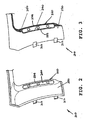
- Figure 2 is a left side view of the cover of Figure 1;
- Figure 3 is a cross-sectional left side view of the cover of Figure 2;
- Figure 4 is a perspective left side view of the cover of Figure 2;
- Figure 5 is a horizontally-sectioned perspective left side view of the cover of Figure 4;
- Figure 6 is a right side view of the power hand tool similar to Figure 1, showing the cover attached on the handle;
- Figure 7 is a cross-sectional view of the handle and cover of Figure 6, taken along line VII-VII;
- Figure 8 is a cross-sectional view of the handle and cover of Figure 6, taken along line VIII-VIII;
- Figure 9 is a cross-sectional view of the handle and cover of Figure 8, taken along line IX-IX;
- Figure 8A is a cross-sectional view of the handle and cover similar to Figure 8, showing the cover unlatched;
- Figure 9A is a cross-sectional view of the handle and cover of Figure 8A, taken along line IXA-IXA;
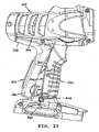
- Figure 10 is a right side view of the power hand tool similar to Figure 6, showing the cover being attached onto or detached from the handle;
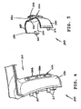
- Figure 11 is a right side view of a second embodiment of a power hand tool in accordance with the invention, having a handle with a cover shown detached;
- Figure 12 is a left side view of the cover of Figure 11;
- Figure 13 is a cross-sectional left side view of the cover of Figure 12;
- Figure 14 is a perspective left side view of the cover of Figure 12; and
- Figure 15 is a horizontally-sectioned perspective left side view of the cover of Figure 14.
- Referring initially to Figures 1 to 10 of the drawings, there is shown a first
power hand tool 10 embodying the invention, which is anelectric hand drill 10 having a handgun-like body 100 that includes a elongate handgrip or handle 200 depending generally at right angles from the gun barrel. In common to all conventional electric hand drills, thebody 100 houses a drive mechanism that incorporates an electric motor and certain gears for transmitting the motor drive to aforemost chuck 110. Thechuck 110 serves to hold and drive a tool implement i.e. a drill bit or screwdriver bit, for example, to rotate about a central axis of thebody 100. Thehandle 200 terminates as a widenedopening 290 for attaching thereto a rechargeable battery pack (not shown). - With the
handle 200 being gripped by a hand of a user, thedrill body 100 can be manipulated to drive a tool bit forwardly to act upon a workpiece, say in an operative direction. - The
handle 200 is integrally connected to thedrill body 100, together being formed by a pair of left and right plastic clam shells secured together by screws. Thehandle 200 has a separateplastic cover 210 attached onto its rear side, which covers about half, the rear half, of thehandle 200, as well as an adjoining underside of a rear end of thedrill body 100, for contact by the palm of the user's hand. The covered portion, designated as 204, is indented for thecover 210 to fit in and lie flush with the rest of thehandle 200. - The
cover 210 has an inverted L-shape and an arcuate cross-section matching with that of thehandle portion 204, including a rearwardly pointingupper end 214 and a downwardly pointinglower end 216. Theupper cover end 214 has a reduced extremity formed by severalsmall tabs 215 for insertion behind alip 205 at the corresponding end of theportion 204. Thelower cover end 216 has an integralrear hook 217 projecting from its inner surface. There are also a number ofother tabs 212 along the left and right side edges of thecover 210. - The
cover 210 is attached to thehandle portion 204 by firstly inter-engaging itsupper end tabs 215 with thelip 205 of the portion 204 (Figure 10) and then pivoting thecover 210 about itsupper end 214 until it lies against theportion 204. Theside tabs 212 of thecover 210 inserted into respective slots on opposite left and right sides of thebody 100/handle 200 ensure a tight fit between the two connected parts. Thelower end 216 of thecover 210 is secured to that of theportion 204 by means of alatching device 300 that being part of thehand drill 10. Thecover 210 may be detached by reversing the described steps. - The
latching device 300 holds thecover 210 securely on theindented portion 204 of thehandle 200 from behind thecover 210; it is built substantially wholly within the lower end of thehandle portion 204 adjacent and generally behind thelower cover end 216. Thelatching device 300 comprises avertical latch member 310 for retaining thecover 210 by itshook 217 and ahorizontal release member 320 for releasing thelatch member 310 from thehook 217. - The
latch member 310 has a bifurcateupper end 312 that forms an open-ended slot for engaging with thecover hook 217 from below, alower end 314, and an intermediate part that presents aninclined surface 316 facing 45° upwards. About thelower end 314 there is disposed acompression coil spring 315 which resiliently biases theoverall latch member 310 linearly upwards with itsupper end 312 into engagement with thecover hook 217. - The
release member 320 takes the form of a generallycylindrical rod 320 which is co-axially slidably received in ahorizontal hole 206 that extends straight through the right half of thehandle 200 and is aligned with theinclined surface 316 of thelatch member 310. Therod 320 has aninner end 322 in contact with theinclined surface 316, and a slightly enlargedouter end 324 staying just wholly within the outer end of thehole 206. A c-clip 324 fitted around theinner end 322 immediately outside the inner end of thehole 206 prevents outward withdrawal of therod 320 from thehole 206. - Under the action of the
spring 315, while thelatch member 310 is raised and thus engages thecover 210 by thehook 217, itsinclined surface 316 displaces therelease rod 320 relatively outermost within thehandle hole 206 through cam action between thesurface 316 and the inner rod end 322 (Figure 8). Therod 320 may be pushed further into thehole 206, inwardly relative to thehandle portion 204, manually by a user pressing at theouter rod end 324, which is preferably indented. - Upon being slid inwards, the
rod 320 displaces thelatch member 310 downwards through reversed cam action between theinner rod end 322 and thesurface 316, thereby disengaging the latch memberupper end 312 from thecover hook 217 and thus releasing the cover 210 (Figure 8A). While being unlatched thecover 210 may be detached from thehandle 200, and it may later be re-attached thereto (with a different cover as desired). - It is important to note that any object that has a suitably small end, i.e. an end that is smaller than the
hole 206, can be used to press at theouter rod end 324. Examples include a ball pen, a small screwdriver or a screw or nail, etc., all of which are readily available especially in a workshop or the like. Thus, no specific tool is required for detaching or attaching thecover 210, and this is convenient to users. - The
outer end 324 of therelease rod 320 is disposed within thehole 206 to avoid accidental depression thereof i.e. unintended detachment of thehandle cover 210. - It is an advantage that the
cover 210 is detachable from thehandle 200 so that it can be replaced by a new cover or by another cover of a different design (see below) as desired. - The
cover 210 has acentral portion 220 facing in a non-operative (rearward) direction opposite to the operative (forward) direction and a pair ofcurved aide portion 230 on at least opposite left and right aides of thecentral portion 220, extending integrally therefrom and together forming a generally C-shaped cross-section. Thecentral portion 220 is elongate as thehandle 200 and extends along its length and almost across opposite upper and lower ends thereof. - The
central cover portion 220 is formed by a flatinner strip 222, from which theside cover portions 230 extend laterally in opposite directions, and a narrowerouter strip 224 extending across upper and lower ends of theinner strip 222. Theouter strip 224 is spaced apart from theinner strip 222, thereby forming a relatively narrow gap in between that locates an elongate inflated enclosure orair bag 240 whose opposite left and right sides are exposed. Theouter strip 224 acts a shield protecting thebag 240 on its outer side. - The outer surface of the
side cover portions 230, together with that of theinner strip 222 of thecentral cover portion 220, is overlaid with a generallythin rubber coating 250 for firm (non-slip) gripping. Theouter strip 224 is made wholly of rubber as an integral extension of therubber coating 250 such that theouter strip 224 is resiliently deformable with theair bag 240. - The left and right sides of the
air bag 240 are pulled in and inter-connected at regular intervals along the length of thebag 240, whereby the cross-section of thebag 240 is maintained especially along its middle section for resilience. - The
air bag 240 and theouter strip 224 thereon, i.e. thecentral cover portion 220, together constitute a resiliently deformable/compressible cushion on thehandle 200 for absorbing and thus reducing the reaction impact, shock or vibration in general acting upon the palm of the user's hand grasping thehandle 200 during operation of thepower tool 10. whilst thecentral cover portion 220 is required to be resiliently deformable for vibration damping, theside cover portions 230 should not has an outer surface that is too soft (in lateral directions at right angles to the operative or drilling direction) to ensure a stable grip on thehandle 200. - Reference is now made to Figures 11 to 15, which show a second electric hand drill 10A embodying the invention, which has generally the same construction as the
first hand drill 10, with equivalent parts designated by the same reference numerals suffixed by a letter "A". The only differences lie in the design of thehandle cover 210A as described below, which is an alternative interchangeable with theearlier cover 210 for use on the same drill handle 200/200A. - The
handle cover 210A likewise has three integrally connectedplastic portions central portion 220A facing rearwards in the non-operative direction and co-extending with thehandle 200A. Thecentral portion 220A includes aflat strip 222A, from which theside portions 230A extend laterally in opposite directions, together having a generally c-shaped cross-section. - The combined outer surface of the
central portion strip 222A and theside portions 230A is overlaid with arubber coating 250A for firm (non-slip) gripping, which includes a relatively thickcentral strip 240A layered on thebase strip 222A. Therubber strip 240A is thicker by reason of thecoating 250A curving over theflat strip 222A in a convex manner. - The
rubber strip 240A is sufficiently thick and is preferably made of ethylene vinyl acetate copolymer to act as a resiliently deformable/compressible pad on thehandle 200A for absorbing and thus reducing the reaction shock or vibration acting upon the palm of the user's hand grasping thehandle 200A. - The
covers 210/210A offer different degree of cushioning effect against shock/vibration of thepower tool 10/10A in use, as well as gripping feels and/or aesthetic appearance (e.g. shape, texture or color). - Both covers 210/210A can be attached/detached relative to the
handle 200/200A in the same manner as described above, or in a different embodiment the cover may be permanently fixed on the power tool body/handle. It is envisaged that the resiliently deformable cushion/pad 240/240A may be attached directly onto the power tool handle, without the use of a separate cover or carrier. - More powerful hand tools, whether they be electrically or pneumatically driven, should normally be held by both hands, in that apart from the main handle (at the rear) there is an auxiliary handle on one side for the other hand or the body includes a handgrip portion on its lower surface (i.e. the belly) for gripping by the other hand. Such an auxiliary handle or handgrip portion may be provided with a cover in accordance with the invention.
- Although hand drills have been explicitly described above, the subject invention is also applicable to any other various types of power hand tools, such as cutters, jig/reciprocating saws, hedge trimmers and router bases/attachments. It is understood that the second handle of a power hand tool, such as the side handle of a hand drill, may likewise be made shock absorbent in accordance with the invention.
- The invention has been given by way of example only, and various other modifications of and/or alterations to the described embodiments may be made by persons skilled in the art without departing from the scope of the invention as specified in the appended claims.
Claims (25)
- A power hand tool comprising:a body having a portion for gripping by a hand of a user using the power hand tool;a drive mechanism including an electric motor housed in the body for driving a tool implement to act upon a workpiece in an operative direction;a cover detachably covering at least part of the portion for contact by the palm of said hand; anda latching device latching the cover on the portion, the latching device including a release member that is manually operable without the use of a specific tool to release the latching device and in turn the cover, whereby the cover is detachable from the portion.
- The power hand tool as claimed in claim 1, characterized in that the release member is supported for manual movement for operation in a linear direction.
- The power hand tool as claimed in claim 1 or claim 2, characterized in that the release member is moveable inwardly relative to the portion.
- The power hand tool as claimed in any preceding claim, characterized in that the latching device includes a latch member engaging the cover to lock the cover, and the release member operatively acts upon the latch member through a cam action to disengage the latch member from the cover.
- The power hand tool as claimed in claim 4, characterized in that the latch member and the release member are movable linearly and at substantially right angles relative to each other.
- The power hand tool as claimed in claim 4 or claim 5, characterized in that the latch member is resiliently biased by a spring into engagement with the cover.
- The power hand tool as claimed in any one of claims 4 to 6, characterized in that the cover has an inner part engaged by the latch member, whereby the cover is locked on the portion.
- The power hand tool as claimed in any one of claims 1 to 7, characterized in that the latching device is located behind the cover and locks the cover on the portion from behind the cover.
- The power hand tool as claimed in any one of claims 1 to 8, characterized in that the latching device is built substantially wholly within the portion.
- The power hand tool as claimed in any one of claims 1 to 9, characterized in that the portion has spaced apart first and second parts and the cover has corresponding first and second parts, the first part of the cover being inter-engaged with the first part of the portion, the second part of the cover being locked by the latching device to the second part of the portion, within which second part of the portion the latching device is located.
- The power hand tool as claimed in claim 10, characterized in that the cover is attached to the portion by inter-engaging the first part of the cover with the first part of the portion, then pivoting the cover about its first part to the portion, and finally latching the second part of the cover to the second part of the portion using the latching device.
- The power hand tool as claimed in any one of claims 1 to 11, characterized in that the body includes a handle by which the power hand tool is in use held by said user, the handle including the portion.
- The power hand tool as claimed in any preceding claim, characterized in that the portion faces in a non-operative direction that is generally opposite to the operative direction, and the cover is resiliently deformable to absorb vibration upon said palm during operation of the power hand tool.
- The power hand tool as claimed in claim 13, characterized in that the cover comprises an inflated enclosure.
- The power hand tool as claimed in claim 13 or claim 14, characterized in that the cover portion comprises a layer of rubber material.
- A power hand tool comprising:a body having a portion for gripping by a hand of a user using the power hand tool;a drive mechanism including an electric motor housed in the body for driving a tool implement to act upon a workpiece in an operative direction; anda cover covering at least part of the portion for contact by the palm of said hand, the cover being resiliently deformable, comprising an inflated enclosure, to absorb vibration upon said palm during operation of the power hand tool.
- The power hand tool as claimed in claim 16, characterized in that the enclosure is elongate and has opposite left and right sides thereof inter-connected at intervals along the length of the enclosure.
- The power hand tool as claimed in claim 16 or claim 17, characterized in that the cover includes a shield on an outer side of the enclosure for protecting the enclosure.
- The power hand tool as claimed in claim 18, characterized in that the enclosure has opposite left and right sides thereof exposed.
- The power hand tool as claimed in any one of claims 16 to 19, characterized in that the cover is detachably fixed on the portion.
- The power hand tool as claimed in claim 20, characterized in including a latching device latching the cover on the portion, the latching device including a release member that is manually operable without the use of a specific tool to release the latch member and in turn the cover, whereby the cover is detachable from the portion.
- The power hand tool as claimed in claim 21, characterized in that the portion has spaced apart first and second parts and the cover has corresponding first and second parts, the first part of the cover being inter-engaged with the first part of the portion, the second part of the cover being locked by the latching device to the second part of the portion, within which second part of the portion the latching device is located.
- The power hand tool as claimed in claim 22, characterized in that the cover is attached to the portion by inter-engaging the first part of the cover with the first part of the portion, then pivoting the cover about its first part to the portion, and finally latching the second part of the cover to the second part of the portion using the latching device.
- The power hand tool as claimed in any one of claims 16 to 23, characterized in that the body includes a handle by which the power hand tool is in use held by said user, the handle including the portion.
- The power hand tool as claimed in any one of claims 16 to 24, characterized in that the portion faces in a non-operative direction that is generally opposite to the operative direction.
Applications Claiming Priority (1)
| Application Number | Priority Date | Filing Date | Title |
|---|---|---|---|
| HK04107163A HK1074731A2 (en) | 2004-09-17 | 2004-09-17 | Power hand tool. |
Publications (1)
| Publication Number | Publication Date |
|---|---|
| EP1637290A1 true EP1637290A1 (en) | 2006-03-22 |
Family
ID=35407195
Family Applications (1)
| Application Number | Title | Priority Date | Filing Date |
|---|---|---|---|
| EP05255782A Withdrawn EP1637290A1 (en) | 2004-09-17 | 2005-09-19 | Power hand tool |
Country Status (3)
| Country | Link |
|---|---|
| EP (1) | EP1637290A1 (en) |
| CN (1) | CN1748955A (en) |
| HK (1) | HK1074731A2 (en) |
Cited By (9)
| Publication number | Priority date | Publication date | Assignee | Title |
|---|---|---|---|---|
| GB2445251B (en) * | 2006-12-22 | 2009-10-07 | Bosch Gmbh Robert | Router |
| US7717191B2 (en) | 2007-11-21 | 2010-05-18 | Black & Decker Inc. | Multi-mode hammer drill with shift lock |
| US7717192B2 (en) | 2007-11-21 | 2010-05-18 | Black & Decker Inc. | Multi-mode drill with mode collar |
| US7735575B2 (en) | 2007-11-21 | 2010-06-15 | Black & Decker Inc. | Hammer drill with hard hammer support structure |
| US7762349B2 (en) | 2007-11-21 | 2010-07-27 | Black & Decker Inc. | Multi-speed drill and transmission with low gear only clutch |
| US7770660B2 (en) | 2007-11-21 | 2010-08-10 | Black & Decker Inc. | Mid-handle drill construction and assembly process |
| US7798245B2 (en) | 2007-11-21 | 2010-09-21 | Black & Decker Inc. | Multi-mode drill with an electronic switching arrangement |
| US7854274B2 (en) | 2007-11-21 | 2010-12-21 | Black & Decker Inc. | Multi-mode drill and transmission sub-assembly including a gear case cover supporting biasing |
| CN102029602A (en) * | 2009-09-28 | 2011-04-27 | 株式会社牧田 | Handle part of hand-held tool |
Families Citing this family (4)
| Publication number | Priority date | Publication date | Assignee | Title |
|---|---|---|---|---|
| CN103358292A (en) * | 2013-07-23 | 2013-10-23 | 钱自财 | Electric handheld tool |
| CN104131742A (en) * | 2014-07-23 | 2014-11-05 | 九江消防装备有限公司 | Damage-free locking device |
| DE102015225864A1 (en) * | 2015-12-18 | 2017-06-22 | Robert Bosch Gmbh | Suction device for a portable machine tool |
| JP6703417B2 (en) * | 2016-02-19 | 2020-06-03 | 株式会社マキタ | Work tools |
Citations (7)
| Publication number | Priority date | Publication date | Assignee | Title |
|---|---|---|---|---|
| US5640741A (en) * | 1994-10-13 | 1997-06-24 | Ryobi Limited | Structure for handle of power tool |
| DE29901003U1 (en) * | 1999-01-21 | 1999-04-01 | Chung Lee Hsin Chih | Handle structure of a power tool |
| WO2000064642A1 (en) * | 1999-04-22 | 2000-11-02 | Scintilla Ag | Supple handle element for electric handtools |
| US20030159251A1 (en) * | 2002-02-28 | 2003-08-28 | Robinson Josh M. | Hand pressure abatement apparatus for use with a power tool |
| US20030177611A1 (en) * | 2002-03-20 | 2003-09-25 | Ching-Hui Lin | Combination of handle with cover |
| US20040081883A1 (en) * | 1999-06-01 | 2004-04-29 | Tom Mooty | Cordless power tool battery release mechanism |
| EP1419856A1 (en) * | 2002-10-28 | 2004-05-19 | Black & Decker Inc. | Handle assembly for tool |
-
2004
- 2004-09-17 HK HK04107163A patent/HK1074731A2/en not_active IP Right Cessation
-
2005
- 2005-09-16 CN CN 200510103973 patent/CN1748955A/en active Pending
- 2005-09-19 EP EP05255782A patent/EP1637290A1/en not_active Withdrawn
Patent Citations (7)
| Publication number | Priority date | Publication date | Assignee | Title |
|---|---|---|---|---|
| US5640741A (en) * | 1994-10-13 | 1997-06-24 | Ryobi Limited | Structure for handle of power tool |
| DE29901003U1 (en) * | 1999-01-21 | 1999-04-01 | Chung Lee Hsin Chih | Handle structure of a power tool |
| WO2000064642A1 (en) * | 1999-04-22 | 2000-11-02 | Scintilla Ag | Supple handle element for electric handtools |
| US20040081883A1 (en) * | 1999-06-01 | 2004-04-29 | Tom Mooty | Cordless power tool battery release mechanism |
| US20030159251A1 (en) * | 2002-02-28 | 2003-08-28 | Robinson Josh M. | Hand pressure abatement apparatus for use with a power tool |
| US20030177611A1 (en) * | 2002-03-20 | 2003-09-25 | Ching-Hui Lin | Combination of handle with cover |
| EP1419856A1 (en) * | 2002-10-28 | 2004-05-19 | Black & Decker Inc. | Handle assembly for tool |
Cited By (12)
| Publication number | Priority date | Publication date | Assignee | Title |
|---|---|---|---|---|
| GB2445251B (en) * | 2006-12-22 | 2009-10-07 | Bosch Gmbh Robert | Router |
| US7717191B2 (en) | 2007-11-21 | 2010-05-18 | Black & Decker Inc. | Multi-mode hammer drill with shift lock |
| US7717192B2 (en) | 2007-11-21 | 2010-05-18 | Black & Decker Inc. | Multi-mode drill with mode collar |
| US7735575B2 (en) | 2007-11-21 | 2010-06-15 | Black & Decker Inc. | Hammer drill with hard hammer support structure |
| US7762349B2 (en) | 2007-11-21 | 2010-07-27 | Black & Decker Inc. | Multi-speed drill and transmission with low gear only clutch |
| US7770660B2 (en) | 2007-11-21 | 2010-08-10 | Black & Decker Inc. | Mid-handle drill construction and assembly process |
| US7798245B2 (en) | 2007-11-21 | 2010-09-21 | Black & Decker Inc. | Multi-mode drill with an electronic switching arrangement |
| US7854274B2 (en) | 2007-11-21 | 2010-12-21 | Black & Decker Inc. | Multi-mode drill and transmission sub-assembly including a gear case cover supporting biasing |
| US7987920B2 (en) | 2007-11-21 | 2011-08-02 | Black & Decker Inc. | Multi-mode drill with mode collar |
| US8109343B2 (en) | 2007-11-21 | 2012-02-07 | Black & Decker Inc. | Multi-mode drill with mode collar |
| US8292001B2 (en) | 2007-11-21 | 2012-10-23 | Black & Decker Inc. | Multi-mode drill with an electronic switching arrangement |
| CN102029602A (en) * | 2009-09-28 | 2011-04-27 | 株式会社牧田 | Handle part of hand-held tool |
Also Published As
| Publication number | Publication date |
|---|---|
| CN1748955A (en) | 2006-03-22 |
| HK1074731A2 (en) | 2005-11-18 |
Similar Documents
| Publication | Publication Date | Title |
|---|---|---|
| EP1637290A1 (en) | Power hand tool | |
| US8261853B2 (en) | Ergonomic handle for a power tool | |
| EP2221150B1 (en) | Ergonomic handle for power tool | |
| EP1021106B1 (en) | Interchangeable grips for power hand tools | |
| US20080168629A1 (en) | Impact tools with slidable grip | |
| CA2792982A1 (en) | Ergonomic hand-held power tool and methods of use | |
| US20040221425A1 (en) | Pry bar ergonomic handle | |
| US20100095537A1 (en) | Tool and method of using same | |
| EP2159010B1 (en) | Power tool | |
| US20130020105A1 (en) | Ergonomic hand-held power tool and methods of use | |
| EP1795311A3 (en) | Power impact tool | |
| WO2005077031A2 (en) | Belt clip for hand-held power tools | |
| US10888987B2 (en) | Power tool ski system and method | |
| EP1479486A3 (en) | Cushion grip handle | |
| US7886641B2 (en) | Push block having retractable heel | |
| US7096974B2 (en) | Handle for a hand-held power tool | |
| JP2001079784A5 (en) | ||
| JP4529550B2 (en) | Portable power tools | |
| US20090070976A1 (en) | Non-Pneumatic Scaler | |
| CA2602874A1 (en) | Five in one set of tools | |
| EP1663585A2 (en) | A rotary power hand tool having a flexible handle and attachment system | |
| JP2009000755A (en) | Portable tool | |
| JP4325383B2 (en) | Electric tool | |
| EP1180420A3 (en) | Carving/planing attachment for a rotary hand tool | |
| USD426448S (en) | Shocking absorbing grip wrap for use on handles of hand tools |
Legal Events
| Date | Code | Title | Description |
|---|---|---|---|
| PUAI | Public reference made under article 153(3) epc to a published international application that has entered the european phase |
Free format text: ORIGINAL CODE: 0009012 |
|
| AK | Designated contracting states |
Kind code of ref document: A1 Designated state(s): AT BE BG CH CY CZ DE DK EE ES FI FR GB GR HU IE IS IT LI LT LU LV MC NL PL PT RO SE SI SK TR |
|
| AX | Request for extension of the european patent |
Extension state: AL BA HR MK YU |
|
| 17P | Request for examination filed |
Effective date: 20060830 |
|
| 17Q | First examination report despatched |
Effective date: 20061002 |
|
| AKX | Designation fees paid |
Designated state(s): DE FR GB |
|
| STAA | Information on the status of an ep patent application or granted ep patent |
Free format text: STATUS: THE APPLICATION IS DEEMED TO BE WITHDRAWN |
|
| 18D | Application deemed to be withdrawn |
Effective date: 20080923 |