EP1639949A1 - Instrument for preparing an implant support surface - Google Patents
Instrument for preparing an implant support surface Download PDFInfo
- Publication number
- EP1639949A1 EP1639949A1 EP05255811A EP05255811A EP1639949A1 EP 1639949 A1 EP1639949 A1 EP 1639949A1 EP 05255811 A EP05255811 A EP 05255811A EP 05255811 A EP05255811 A EP 05255811A EP 1639949 A1 EP1639949 A1 EP 1639949A1
- Authority
- EP
- European Patent Office
- Prior art keywords
- glenoid
- feature
- guide
- instrument
- tool
- Prior art date
- Legal status (The legal status is an assumption and is not a legal conclusion. Google has not performed a legal analysis and makes no representation as to the accuracy of the status listed.)
- Granted
Links
- 0 CC1(C)*(C2)C2C*1 Chemical compound CC1(C)*(C2)C2C*1 0.000 description 1
Images


Classifications
-
- A—HUMAN NECESSITIES
- A61—MEDICAL OR VETERINARY SCIENCE; HYGIENE
- A61F—FILTERS IMPLANTABLE INTO BLOOD VESSELS; PROSTHESES; DEVICES PROVIDING PATENCY TO, OR PREVENTING COLLAPSING OF, TUBULAR STRUCTURES OF THE BODY, e.g. STENTS; ORTHOPAEDIC, NURSING OR CONTRACEPTIVE DEVICES; FOMENTATION; TREATMENT OR PROTECTION OF EYES OR EARS; BANDAGES, DRESSINGS OR ABSORBENT PADS; FIRST-AID KITS
- A61F2/00—Filters implantable into blood vessels; Prostheses, i.e. artificial substitutes or replacements for parts of the body; Appliances for connecting them with the body; Devices providing patency to, or preventing collapsing of, tubular structures of the body, e.g. stents
- A61F2/02—Prostheses implantable into the body
- A61F2/30—Joints
- A61F2/40—Joints for shoulders
- A61F2/4081—Glenoid components, e.g. cups
-
- A—HUMAN NECESSITIES
- A61—MEDICAL OR VETERINARY SCIENCE; HYGIENE
- A61B—DIAGNOSIS; SURGERY; IDENTIFICATION
- A61B17/00—Surgical instruments, devices or methods, e.g. tourniquets
- A61B17/16—Bone cutting, breaking or removal means other than saws, e.g. Osteoclasts; Drills or chisels for bones; Trepans
- A61B17/1613—Component parts
- A61B17/1615—Drill bits, i.e. rotating tools extending from a handpiece to contact the worked material
- A61B17/1617—Drill bits, i.e. rotating tools extending from a handpiece to contact the worked material with mobile or detachable parts
-
- A—HUMAN NECESSITIES
- A61—MEDICAL OR VETERINARY SCIENCE; HYGIENE
- A61B—DIAGNOSIS; SURGERY; IDENTIFICATION
- A61B17/00—Surgical instruments, devices or methods, e.g. tourniquets
- A61B17/16—Bone cutting, breaking or removal means other than saws, e.g. Osteoclasts; Drills or chisels for bones; Trepans
- A61B17/17—Guides or aligning means for drills, mills, pins or wires
- A61B17/1739—Guides or aligning means for drills, mills, pins or wires specially adapted for particular parts of the body
- A61B17/1778—Guides or aligning means for drills, mills, pins or wires specially adapted for particular parts of the body for the shoulder
-
- A—HUMAN NECESSITIES
- A61—MEDICAL OR VETERINARY SCIENCE; HYGIENE
- A61F—FILTERS IMPLANTABLE INTO BLOOD VESSELS; PROSTHESES; DEVICES PROVIDING PATENCY TO, OR PREVENTING COLLAPSING OF, TUBULAR STRUCTURES OF THE BODY, e.g. STENTS; ORTHOPAEDIC, NURSING OR CONTRACEPTIVE DEVICES; FOMENTATION; TREATMENT OR PROTECTION OF EYES OR EARS; BANDAGES, DRESSINGS OR ABSORBENT PADS; FIRST-AID KITS
- A61F2/00—Filters implantable into blood vessels; Prostheses, i.e. artificial substitutes or replacements for parts of the body; Appliances for connecting them with the body; Devices providing patency to, or preventing collapsing of, tubular structures of the body, e.g. stents
- A61F2/02—Prostheses implantable into the body
- A61F2/30—Joints
- A61F2/46—Special tools or methods for implanting or extracting artificial joints, accessories, bone grafts or substitutes, or particular adaptations therefor
- A61F2/4603—Special tools or methods for implanting or extracting artificial joints, accessories, bone grafts or substitutes, or particular adaptations therefor for insertion or extraction of endoprosthetic joints or of accessories thereof
- A61F2/4612—Special tools or methods for implanting or extracting artificial joints, accessories, bone grafts or substitutes, or particular adaptations therefor for insertion or extraction of endoprosthetic joints or of accessories thereof of shoulders
-
- A—HUMAN NECESSITIES
- A61—MEDICAL OR VETERINARY SCIENCE; HYGIENE
- A61B—DIAGNOSIS; SURGERY; IDENTIFICATION
- A61B17/00—Surgical instruments, devices or methods, e.g. tourniquets
- A61B17/16—Bone cutting, breaking or removal means other than saws, e.g. Osteoclasts; Drills or chisels for bones; Trepans
- A61B17/1662—Bone cutting, breaking or removal means other than saws, e.g. Osteoclasts; Drills or chisels for bones; Trepans for particular parts of the body
- A61B17/1684—Bone cutting, breaking or removal means other than saws, e.g. Osteoclasts; Drills or chisels for bones; Trepans for particular parts of the body for the shoulder
-
- A—HUMAN NECESSITIES
- A61—MEDICAL OR VETERINARY SCIENCE; HYGIENE
- A61B—DIAGNOSIS; SURGERY; IDENTIFICATION
- A61B17/00—Surgical instruments, devices or methods, e.g. tourniquets
- A61B17/16—Bone cutting, breaking or removal means other than saws, e.g. Osteoclasts; Drills or chisels for bones; Trepans
- A61B17/17—Guides or aligning means for drills, mills, pins or wires
- A61B17/1739—Guides or aligning means for drills, mills, pins or wires specially adapted for particular parts of the body
- A61B17/1764—Guides or aligning means for drills, mills, pins or wires specially adapted for particular parts of the body for the knee
-
- A—HUMAN NECESSITIES
- A61—MEDICAL OR VETERINARY SCIENCE; HYGIENE
- A61B—DIAGNOSIS; SURGERY; IDENTIFICATION
- A61B17/00—Surgical instruments, devices or methods, e.g. tourniquets
- A61B17/16—Bone cutting, breaking or removal means other than saws, e.g. Osteoclasts; Drills or chisels for bones; Trepans
- A61B2017/1602—Mills
-
- A—HUMAN NECESSITIES
- A61—MEDICAL OR VETERINARY SCIENCE; HYGIENE
- A61F—FILTERS IMPLANTABLE INTO BLOOD VESSELS; PROSTHESES; DEVICES PROVIDING PATENCY TO, OR PREVENTING COLLAPSING OF, TUBULAR STRUCTURES OF THE BODY, e.g. STENTS; ORTHOPAEDIC, NURSING OR CONTRACEPTIVE DEVICES; FOMENTATION; TREATMENT OR PROTECTION OF EYES OR EARS; BANDAGES, DRESSINGS OR ABSORBENT PADS; FIRST-AID KITS
- A61F2/00—Filters implantable into blood vessels; Prostheses, i.e. artificial substitutes or replacements for parts of the body; Appliances for connecting them with the body; Devices providing patency to, or preventing collapsing of, tubular structures of the body, e.g. stents
- A61F2/02—Prostheses implantable into the body
- A61F2/30—Joints
- A61F2/40—Joints for shoulders
-
- A—HUMAN NECESSITIES
- A61—MEDICAL OR VETERINARY SCIENCE; HYGIENE
- A61F—FILTERS IMPLANTABLE INTO BLOOD VESSELS; PROSTHESES; DEVICES PROVIDING PATENCY TO, OR PREVENTING COLLAPSING OF, TUBULAR STRUCTURES OF THE BODY, e.g. STENTS; ORTHOPAEDIC, NURSING OR CONTRACEPTIVE DEVICES; FOMENTATION; TREATMENT OR PROTECTION OF EYES OR EARS; BANDAGES, DRESSINGS OR ABSORBENT PADS; FIRST-AID KITS
- A61F2/00—Filters implantable into blood vessels; Prostheses, i.e. artificial substitutes or replacements for parts of the body; Appliances for connecting them with the body; Devices providing patency to, or preventing collapsing of, tubular structures of the body, e.g. stents
- A61F2/02—Prostheses implantable into the body
- A61F2/30—Joints
- A61F2002/30001—Additional features of subject-matter classified in A61F2/28, A61F2/30 and subgroups thereof
- A61F2002/30316—The prosthesis having different structural features at different locations within the same prosthesis; Connections between prosthetic parts; Special structural features of bone or joint prostheses not otherwise provided for
- A61F2002/30317—The prosthesis having different structural features at different locations within the same prosthesis
- A61F2002/30324—The prosthesis having different structural features at different locations within the same prosthesis differing in thickness
-
- A—HUMAN NECESSITIES
- A61—MEDICAL OR VETERINARY SCIENCE; HYGIENE
- A61F—FILTERS IMPLANTABLE INTO BLOOD VESSELS; PROSTHESES; DEVICES PROVIDING PATENCY TO, OR PREVENTING COLLAPSING OF, TUBULAR STRUCTURES OF THE BODY, e.g. STENTS; ORTHOPAEDIC, NURSING OR CONTRACEPTIVE DEVICES; FOMENTATION; TREATMENT OR PROTECTION OF EYES OR EARS; BANDAGES, DRESSINGS OR ABSORBENT PADS; FIRST-AID KITS
- A61F2/00—Filters implantable into blood vessels; Prostheses, i.e. artificial substitutes or replacements for parts of the body; Appliances for connecting them with the body; Devices providing patency to, or preventing collapsing of, tubular structures of the body, e.g. stents
- A61F2/02—Prostheses implantable into the body
- A61F2/30—Joints
- A61F2/30767—Special external or bone-contacting surface, e.g. coating for improving bone ingrowth
- A61F2/30771—Special external or bone-contacting surface, e.g. coating for improving bone ingrowth applied in original prostheses, e.g. holes or grooves
- A61F2002/30878—Special external or bone-contacting surface, e.g. coating for improving bone ingrowth applied in original prostheses, e.g. holes or grooves with non-sharp protrusions, for instance contacting the bone for anchoring, e.g. keels, pegs, pins, posts, shanks, stems, struts
- A61F2002/30891—Plurality of protrusions
- A61F2002/30892—Plurality of protrusions parallel
-
- A—HUMAN NECESSITIES
- A61—MEDICAL OR VETERINARY SCIENCE; HYGIENE
- A61F—FILTERS IMPLANTABLE INTO BLOOD VESSELS; PROSTHESES; DEVICES PROVIDING PATENCY TO, OR PREVENTING COLLAPSING OF, TUBULAR STRUCTURES OF THE BODY, e.g. STENTS; ORTHOPAEDIC, NURSING OR CONTRACEPTIVE DEVICES; FOMENTATION; TREATMENT OR PROTECTION OF EYES OR EARS; BANDAGES, DRESSINGS OR ABSORBENT PADS; FIRST-AID KITS
- A61F2250/00—Special features of prostheses classified in groups A61F2/00 - A61F2/26 or A61F2/82 or A61F9/00 or A61F11/00 or subgroups thereof
- A61F2250/0014—Special features of prostheses classified in groups A61F2/00 - A61F2/26 or A61F2/82 or A61F9/00 or A61F11/00 or subgroups thereof having different values of a given property or geometrical feature, e.g. mechanical property or material property, at different locations within the same prosthesis
- A61F2250/0036—Special features of prostheses classified in groups A61F2/00 - A61F2/26 or A61F2/82 or A61F9/00 or A61F11/00 or subgroups thereof having different values of a given property or geometrical feature, e.g. mechanical property or material property, at different locations within the same prosthesis differing in thickness
Definitions
- the present invention relates generally to the field of orthopaedics, and more particularly, to an implant for use in arthroplasty.
- a humeral component having a head portion is utilized to replace the natural head portion of the arm bone or humerus.
- the humeral component may include an elongated intramedullary stem which is utilized to secure the humeral component to the patient's humerus.
- the natural glenoid surface of the scapula is resurfaced or otherwise replaced with a glenoid component that provides a bearing surface for the head portion of the humeral component.
- the humeral component may be made without a stem or with a short stem.
- the need for a shoulder replacement procedure may be created by the presence of any one of a number of conditions.
- One such condition is the deterioration of the patient's scapula in the glenoid surface as a result of, for example, glenohumeral arthritis.
- erosion of the patient's scapula may be observed.
- the erosion may be asymmetric, anterior or posterior.
- Posterior erosion of on the glenoid surface is particularly common. Such erosion of the scapula renders treatment difficult, if not impossible, with a conventional glenoid prosthesis.
- glenoid prostheses In order to treat a condition in which a portion of the scapula has been eroded, a number of glenoid prostheses have heretofore been designed. Such glenoid prostheses, known generally as augmented glenoid prostheses, have a posterior edge that is thicker than the corresponding anterior edge.
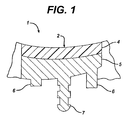
- FIG. 1 a heretofore-designed augmented glenoid component 1 is shown.
- the glenoid component 1 has a metallic backing component 5 and plastic insert 4.
- the thickness of the metallic backing component 5 gradually increases from an anterior edge to a posterior edge thereof.
- the arcuate-shaped medial surface 2 may over time lead to loosening of the augmented glenoid component 1, thereby potentially necessitating additional surgical procedures to replace or reseat the component 1.
- a relatively high shear load is created along the implant-to-bone interface when the component 1 is implanted.
- the presence of a high shear load along the implant-to-bone interface tends to also cause loosening of the component 1 over a period of time. Post-operative loosening is the largest cause of failures of implanted glenoid components.
- the metal backing may include additional features in the form of, for example, pegs 6 and centre peg 7 to provide additional support of the glenoid implant on the scapula 3.
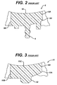
- FIG. 2 Another known augmented glenoid component 8 is shown in FIG. 2.
- the glenoid component 8 has a single component plastic body 9A.
- the thickness of the plastic body 9A gradually increases from an anterior edge 8A to a posterior edge 8B thereof thereby creating a relatively smooth, arcuate-shaped medial surface 10 from which a number of posts or pegs 8 extend.
- the design of this augmented glenoid component 8 suffers from at least the same drawbacks as the glenoid component 1.
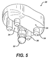
- FIG. 3 Another known augmented glenoid component 11 is shown in FIG. 3.
- the glenoid component 11 also has a single component plastic body 11A.
- the thickness of the plastic body 9B gradually increases from an anterior edge 11A to a posterior edge 11B thereof thereby creating a relatively smooth medial surface 11C from which a keel 12 extends.
- the augmented glenoid component disclosed in US-6699289 requires a stepped pocket or locating surface for the augmented glenoid component. Such a stepped surface is very difficult to create. Certain processes for preparing the glenoid fossa for such a component can consist merely of hand or power tools, which are manually guided to prepare the cavity for receiving the augmented glenoid component.
- the invention provides an instrument for preparing a surface of a joint, the surface adapted for receiving a glenoid component having a feature closely conforming to the glenoid surface, the prosthetic component providing a bearing surface for a portion of a long bone, the instrument comprising:
- the invention provides an instrument for preparing a feature on a scapula, the feature adapted for receiving an augmented glenoid component for providing a bearing surface for a head portion of a humerus, the instrument comprising:
- the invention provides an instrument kit for preparing a glenoid of a scapula, the glenoid adapted for receiving a glenoid component having a feature closely conforming to the glenoid, the glenoid component providing a bearing surface for a head portion of a humerus, the instrument kit comprising:
- Instruments provided by the present invention can be used in a method for performing arthroplasty on a glenoid comprising the steps of:
- Instruments provided by the present invention can produce a geometry of a complex nature for an implant surface when irregular bone loss has occurred and an augmented implant component is advised.
- a device and technique are provided by which the surgeon can mill the glenoid surface in a bone preserving fashion.
- a step is created in the glenoid fossa that replicates the backside surface of an augmented step glenoid implant such as disclosed in US-6699289.
- the instrumentation may include a rotating mill with a sleeve that has a fixed pivoting axis to create a cylindrical shape in the posterior aspect of the eroded glenoid fossa.
- This mill with the pivoting axis, engages a guide that prescribes or limits the proper depth for the step.
- This guide can be instructed in many ways that permit the mill to plunge into the posterior glenoid and then pivot on its axis while milling the bone.
- the device is used to create a cylindrical step in the glenoid so that the glenoid implant can be fully supported.
- This step glenoid of the glenoid implant and underlying bony support permits forces to be transmitted to the scapula in a manner that greatly reduces sheer. By reducing the risk of high sheer it is believed the implant will be more stable and less likely to result in loosening and failure.
- two distinct devices may work in concert to create a desired step geometry for the augmented step glenoid implant.
- the first of these devices is a milling device with a cutting head that embodies a specific shape matching the cross-sectional shape of the step portion of glenoid implant.
- the milling device is connected to a shaft for attachment to a power driven device such as a drill.
- a power driven device such as a drill.
- Around the cutting head is a sleeve that has a pivoting axis at a specific position on the shaft such that when the cutting head is fully extended from the shaft, the cutting head is at a fixed known position relative to the pivoting axis. This permits a reproducible cylindrical geometry to be milled into the bone.
- the cutting head and sleeve may not move relative to each other and the cutting head may be in a fixed relationship with the pivoting axis on the sleeve.
- the other device is a positioning jig that permits the surgeon to accurately place in a reproducible manner the milling device such that the mill removes only the bone necessary to match a glenoid implant to the patients condition.
- This jig defines a depth of cut as well as accurately positioning the cutter so that the device mills the bone longitudinally along the axis of the glenoid fossa. Only the posterior eroded bone is resurfaced to a defined shape matching the implant.
- the jig may accomplish this task while only permitting the rotation of the pivoting axis defined on the mill sleeve.
- the translation of the mill device may be permitted in a medial lateral direction.
- An end stop defines the depth of the step relative to the reamed anterior portion of the glenoid fossa.
- the two devices function together to create a reproducible geometry on the glenoid where posterior bone loss exists permitting the use of a posterior augmented glenoid implant.
- an instrument for preparing a surface of a joint The surface is adapted for receiving a prosthesis component having a feature closely conforming to the surface.
- the prosthesis component provides a bearing surface for a portion of a long bone.
- the instrument includes a guide having a first feature and a second feature and a tool.
- the tool is used for cooperation with the first feature for preparing the surface.
- the first feature is adapted to at least partially control the position of the tool as it prepares the surface.
- the second feature is adapted to assist in positioning of the guide with respect to the joint.
- an instrument for preparing a feature on a scapula is adapted for receiving an augmented glenoid component for providing a bearing surface for a head portion of a humerus.
- the instrument includes a guide defining a guiding feature and a locating feature and a tool.
- the tool is used for cooperation with the guiding feature for preparing the feature.
- the guiding feature is adapted to at least partially guiding the tool as it prepares the glenoid surface.
- the locating feature is adapted to assist in locating the guide with respect to the scapula.
- an instrument kit for use in preparing a glenoid of a scapula.
- the glenoid is adapted for receiving a glenoid component having a feature closely conforming to the glenoid.
- the glenoid component provides a bearing surface for a head portion of a humerus.
- the instrument kit includes a first portion tool for preparing a first portion of the glenoid of a scapula and a second portion tool assembly for preparing a second portion of the glenoid of a scapula. A substantial portion of the second portion tool is spaced from the first portion.
- a method for performing arthroplasty on a glenoid includes the steps of determining a reference location on the glenoid and preparing a location feature in the glenoid corresponding to the reference location.
- the method also includes the steps of providing a cutting guide, securing the cutting guide to the location feature, and providing a cutter.
- the method also includes the steps of preparing a cavity in the glenoid with the cutter, using the cutting guide to at least partially control the position of the cutter as it prepares the cavity.
- the method further includes the steps of providing a glenoid implant and implanting the glenoid implant onto the cavity.
- the technical advantages of the present invention include the ability to reproduce the complex geometry in a glenoid to replicate and support a posterior augmented glenoid.
- an instrument kit for preparing a glenoid scapula is provided.
- the glenoid is adapted for receiving a glenoid component having a feature closely forming to the glenoid.
- the glenoid component provides a bearing surface for a head portion of a humerus.
- the instrument kit includes a first portion tool for preparing a first portion of the glenoid and a second portion of the glenoid. A substantial portion of the second portion is spaced from the first portion.
- the second portion tool assembly includes a guide having a first feature and a second feature and a second portion tool. The second portion tool cooperates with a first feature for preparing the second portion of the glenoid. The first feature is adapted to at least partially to control the position of the second portion of the tool as prepares the second glenoid surface.
- the guide and tools provides a reproducible complex geometry.
- the present invention provides for a reproducible complex geometry and a glenoid to replicate and support the posterior augmented glenoid.
- an instrument kit is provided with a first portion tool for preparing a first portion of the glenoid and a second portion tool for preparing a second portion of the glenoid.
- the second portion tool cooperates with the first feature prepared by the first portion tool.
- the guide includes a base and a restraining component to guide the tool in a position normal to the articulating surface.
- an instrument kit for preparing a glenoid of a scapula including a first portion tool for preparing a first portion of the glenoid and a second portion tool assembly.
- the second portion tool assembly is supported by the surface prepared by the first portion tool.
- the second portion tool assembly includes a rotatable tool and a cylindrical tube surrounding the tool.
- the cylindrical tube is pivotally attached to a bearing to provide a shape similar to that of the posterior augmented portion of the posterior augmented glenoid.
- an instrument kit including a first portion tool for preparing a first portion and a second portion tool assembly including a guide supported by the surface prepared by the first portion tool and a second portion tool for cooperating with the guide.
- the guide and the second portion tool act in concert to define the depth of cut.
- an instrument kit is provided with a first portion tool and a second portion tool assembly including a guide supported by the surface prepared by the first portion tool.
- the second portion tool assembly includes a guide having a base and a restraining component. The restraining component restrains the second portion tool to provide for an accurate position of the cutter.
- the present invention provides for a guide for accurately positioning the cutter.
- the technical advantages of the present invention also include the ability of the instrument of the present invention to be used for right and left hand shoulders.
- the instrument kit includes a guide, which may be symmetrically designed. By being symmetrically designed, the guide may be used for both right and left-hand shoulders.
- the present invention provides for an instrument that can be used for right and left hand shoulders.
- the technical advantages of the present invention further include the ability of the instrument to be used for all sizes and shapes of glenoid implants.
- the instrument includes a first portion tool for preparing a first portion of the glenoid and a second portion tool including a guide being supported by the surface prepared by the first portion tool and a second portion tool to be constrained by the guide.
- the guide may be modular or may include an internal component or bushing to provide for different diameters of the second portion tool.
- the first portion tool may be provided with different sizes to provide for a variety of glenoid implants.
- the present invention provides for an instrument that may be used for all sizes of glenoid implants.
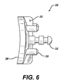
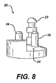
- FIG. 4-8 show a glenoid component 20 which may be used in a cavity prepared by the instrument of the present invention.
- the glenoid component 20 is in the form of an augmented glenoid and may, as shown in FIG. 4-8 include a buttress22 separating a first mounting surface 24 from a second mounting surface 26.
- the glenoid component 20 may include an articulating surface 28 positioned opposed to the mounting surfaces 24 and 26.
- the augmented glenoid component 20 may include additional features to help secure the glenoid component 20 to the scapula.
- the first mounting surface 24 may include first pegs 30 extending from the mounting surface 24 as well as a central peg 32.
- the second mounting surface 26 may also include pegs 30 for extending from the mounting surface 26.
- the second mounting surface and the articulating surface 28 define a posterior augment 36 positioned between the mounting surface 26 and the articulating surface 28.
- the posterior augment 36 provides support for the posterior erosion of the glenoid.
- natural glenoid 38 of scapula 40 is shown.
- the natural glenoid 38 includes a portion 3 of the scapula 40 with a surface 42 describing posterior erosion.
- the scapula 40 is shown with a first milled surface 44 extracted from the natural glenoid 38 and a pocket 46 machined with the instruments of the present invention shown removing the posterior erosion surface 42.
- the machined glenoid surface 44 and the pocket 46 may be prepared utilizing the instruments of the present invention.
- the glenoid component 20 of FIGS. 4-8 is shown in position above on the pocket 46 and glenoid surfaces 44 prepared by the instruments of the present invention.
- the force F from the patient may be supported by resistance forces R1 and R2 extending from the prepared glenoid surface 44 and the pocket 46 respectively.
- the forces R1, R2, and F are all collinear.
- the instrument of the present invention provides for a posterior augmented glenoid 20, which provides for normal forces and minimizes shear forces to provide for less shear and a more stable glenoid implant that is less likely to loosen during use.
- the glenoid fossa 38 includes a posteriorly eroded surface 42 with the healthy glenoid surface shown in phantom as surface 48.
- instrumentation and a corresponding method are shown for preparing an implant support surface for a glenoid implant.
- an alignment pin 100 is shown in position in the scapula 40.
- the alignment pin 100 may include, for example, a point or cutting edge 102 for use in cutting bone in the installation process of the alignment pin 100.
- the alignment pin 100 may further include external threads 104 for assisting in the insertion of the alignment pin 100.
- the alignment pin 100 may be a part of an instrument set 101.
- the alignment pin 100 may be positioned in the glenoid fossa 38 of the scapula 40 in any suitable manner.
- the alignment pin 100 may be manually inserted.
- the alignment pin may be inserted by hand or with the use of, for example, a power tool, for example, a drill 106.
- the alignment pin 100 may be positioned manually or may as shown in FIG. 13, may be guided by, for example, guide 108 that is positioned against outer surface 110 of the scapula 40.
- the alignment pin 100 may be inserted using diagnostic techniques such that using a fluoroscope or may alternatively be positioned using computer aided surgical devices.
- the alignment pin 100 may be centrally positioned in the glenoid fossa 38.
- the guide 108 and the drill 106 may also be part of the instrument set 101.
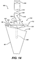
- a first portion tool 110 in the form of, for example, an end mill is shown.
- the end mill 110 includes a cutter 112 to which shank 114 is attached.
- the end mill 110 includes the central opening 116.
- the central opening 116 is sized for sliding engagement with alignment pin 100.
- the end mill 110 may also be part of the instrument set 101.
- the end mill 110 is positioned above the glenoid fossa 38 and the alignment pin 100 is engaged with opening 116 to advance the end mill 110 in the direction of arrow 118 until cutting edge 120 of the cutter 112 engages with the glenoid fossa 38.
- the cutting edge 120 is utilized to form first portion 122 of prepared surface 124.
- the first portion 122 of the prepared surface 124 may have any shape.
- the first portion 122 of the prepared surface 124 may have a shape defined by cutting edge 120 of the cutter 112.
- the cutter 112 may have any suitable shape, for simplicity and is shown in FIG. 14, the cutter 112 has a cutting edge 120 defined by a radius R extending from origin 126.
- the cutting edge 120 thus is convex and may be, as shown in FIG. 14, a portion of a sphere.
- the first portion 122 is generally concaved.
- the end mill 110 may be manually rotated in the direction of arrow 128 by any suitable method.
- the end mill 110 may be manually rotated or rotated by a tool in the form of, for example, a drill 106.
- a tool in the form of, for example, a drill 106.
- the glenoid fossa 38 of the scapula 20 is machined until the entire concave portion 122 is a prepared surface.
- first drill guide 130 is shown as part of the instrument set 101 of the present invention.
- the first drill guide 130 is utilized after the concave first portion 122 has been prepared by the first portion tool 110 of FIG. 14.
- the first drill guide 130 includes a base 132 having a contact surface 134 for contact with the prepared surface 122 of the scapula 40.
- the locating surface 134 preferably has the shape closely conform with the prepared surface 122.
- the contact surface 134 is preferably generally convex.
- the first drill guide 130 further may include an opening 136 for cooperation with alignment pin 101.
- the opening 136 is sized for slideably fitting the alignment pin 100.
- First drill guide 130 is installed onto the scapula 40 by advancing the first drill guide 130 in the direction of arrow 138 until the opening 136 of the base 132 is in alignment with alignment pin 100 with which the first drill guide 130 is thereby aligned.
- the alignment pin 100 is slidably fitted to opening 136 of the first drill guide 130 .
- the first opening 136 of the drill guide 136 is then mated with the alignment pin 100 until convex surface 134 of the base 132 is seated against the prepared surface 122 of the scapula 40. In this position the first drill guide 130 is seated in location for its use.
- the first drill guide 130 further includes a guiding feature 140 in the form of, for example, bushing or opening for receiving a drill. It should be appreciated and shown in FIG. 15, that the first drill guide 130 may include a handle 142 for assisting in the proper positioning of the first drill guide 130 against the scapula 40.
- a first peg tool 144 in the form of, for example, a drill is fitted into drill guide 140 and advanced downwardly in the direction of arrow 138 forming first peg opening 146 in the scapula 40.
- a stop 148 may be positioned on the drill 144 for seating against the base 132 to limit the downward motion of the drill 144 and thus set the proper depth for the opening 146.
- the first drill guide 130 may be removed from the glenoid fossa 38.
- alignment pin 100 may also be removed from the glenoid fossa 38.
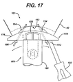
- the instrument set 101 of the present invention may further include an instrument 150 for preparing a mounting pocket 152 posteriorly in the scapula 40.
- the posterior pocket preparing instrument 150 as shown in FIG. 16 includes a guide in the form of cutting guide 156 as well as, a tool in the form of, as shown in FIG. 16, of a milling cutter 158.
- the instrument 150 is utilized to prepare the glenoid surface or mounting pocket 152 of the scapula 40.
- the glenoid surface or mounting pocket 152 is adapted for receiving a glenoid component having a feature closely conforming to the glenoid surface.
- the glenoid component may be for example, glenoid component 20, as shown in FIGS. 4-8, and may provide a bearing surface for the head portion of a humerus.
- the cutting guide 156 includes a first feature 160 in the form of a guiding feature adapted to at least partially control the position of the tool 158 as it prepares the mounting pocket 152. As shown in FIG. 16, the cutting guide 156 further includes the second feature 162. The second feature 162 is adapted to assist in positioning of the cutting guide 156 with respect to the scapula 40.
- the first feature or guiding feature 160 may have any suitable size, shape and configuration for guiding the tool 158 to prepare the mounting pocket 152.
- the guiding feature 160 may be defined by a wall 164 in the guiding feature for forming a cylindrical opening 166.
- the wall 164 may form a hollow cylinder 168.
- the wall 164, the opening 166, and cylinder 168 may constrain the tool or the cutter 158.
- the first feature or guiding feature 160 may be moveable with respect to the cutting guide 156.
- the cylinder 168 as shown in FIG. 16 may rotate relative to the cutting guide 156 in the direction of the arrows 170.
- the guiding feature or first feature 160 may as shown in FIG. 16, include a bearing 172.
- the bearing 172 may include a post 174 extending outwardly from base 176,of the cutting guide 156.
- the bearing 172 may be in the form of a journal bearing or in the form of a trunnion.
- the cylinder 168 may pivot about the bearing 172 to prepare the mounting pocket 152.
- the bearing 172 may define a bearing centerline 178 about which the tool 158 is pivotally attached.
- the centerline 178 may, as shown in FIG. 16, be generally parallel to the base 176.
- the cutting guide 176 may further include a handle 180 for supporting and guiding the cutting guide 156.
- the second feature or position feature 162 may have any suitable shape or form capable of positioning the cutting guide 156 with respect to the scapula 40.
- the cutting guide 156 may include a mounting surface 182 formed in base 176 of the cutting guide 156.
- the mounting surface 182 preferably and is shown in FIG. 16, has a shape compatible with the prepared surface 122 of the scapula 40.
- the mounting surface 182 is generally convex and may, for example, have a generally hemispherical shape.
- the positioning feature 162 may in addition to the mounting surface 182 include a protrusion in the form of, for example, a pin 184.
- the pin 184 extends outwardly from mounting surface 182 of the base 176 of the cutting guide 156.
- the pin 184 may be generally cylindrical and adapted for a sliding fit within opening or peg hole 146 formed in the scapula 40.
- the cutting guide 156 is installed by grasping the handle 180 and advancing the cutting guide 156 toward the scapula 40 in the direction of arrow 186.
- the pin 184 is aligned with peg hole 146 and the cutting guide 156 is advanced until the mounting surface 182 sits against prepared surface 122 of the scapula.
- the tool in the form of, for example, milling cutter 158 is advanced toward the scapula 40 in the direction of arrow 188 until the milling cutter 158 is in a full depth position.
- the milling cutter 158 is rotated about bearing 172 in the direction of arrows 170 about axis 178 until the mounting pocket 152 is fully prepared.
- the cutting guide 156 is removed from the scapula 40.
- the tool or milling cutter 158 may be rotated by any suitable method for example, milling cutter 158 may be manually rotated, or preferably, may be rotated by use of a power tool, for example, by drill 106.
- cutting guide 156 may be further secured by additional features to secure the cutting guide 156 to the scapula 40.
- mounting screws for example, first mounting screw 190 and second mounting screw 192 may be secured through openings 194 in the base 176 of the cutting guide 156.
- the mounting screws 190 and 192 are used to avoid requiring the holding of the cutting guide 156 in place manually while the mounting pocket 152 is prepared.
- a second drill guide 196 may be utilized as a part of the instrument set 101.
- the second drill guide 196 is used to prepare second peg hole 198 for receiving the second peg (not shown) of the glenoid component 20 of FIGS. 4-8.
- the second drill guide 196 may have any suitable size, shape, and configuration capable of guiding a tool, for example, a second drill 200 for preparing the second peg 198.
- the second drill guide 196 may, for example, include a base 202 and may include a handle 204 extending from the base 202 for assisting in positioning and securing the second drill guide 196 against the scapula 40.
- the second drill guide 196 may include a positioning feature 162 in the form of, for example, mounting surface 206.
- the mounting surface 206 may be formed on base 202.
- the mounting surface 206 is adapted for positioning the base 202 against prepared surface 122 of the scapula 40.
- the mounting surface 206 is preferably closely conforming to the prepared surface 122 and may, as shown in FIG. 18, be generally convex.
- the mounting surface 206 may, as shown in FIG. 18, be generally hemispherical.
- the second drill guide 196 may further include a guiding feature 210 used in guiding the second drill 200 when preparing the second peg hole 198.
- the guiding feature 210 may as shown in FIG.18, be in the form of a bushing or a cylindrical opening formation base 202 of the drill guide 196.
- the bushing 210 may be generally cylindrical and have a shape generally conforming to and providing rotating clearance for the second drill 200.
- the second drill guide 196 When installing the second drill guide 196 into the scapula 40, the second drill guide 196 is advanced in the direction of arrow 212.
- the second peg alignment pin 208 is aligned with the second peg hole 146 and the second drill guide 196 is advanced in the direction of 212 until the mounting surface 206 of the base 202 of the drill guide 196 is seated securely prepared surface 122 of the scapula 40.
- the second drill 200 is advanced downwardly in the direction of arrow 212 until the second drill 202 is fully seated in the scapula 40 and the second peg hole 198 is properly prepared.
- the second drill guide 196 may optionally include a feature for controlling the depth of the second drill 202 and the corresponding depth of the second peg hole 198.
- the depth control feature may be in the form of the stop 214 positioned on the second drill 202.
- the second drill 202 may be advanced downwardly in the direction of arrow 212 until the stop 214 sits against the base of the second drill guide 196.
- the second drill guide may be removed from the scapula 40.
- the glenoid component 20 is shown in position above the mounting pocket 152 prepared by the instrument set 101 of the present invention.
- the prepared surface 122 of the mounting pocket 152, as well as, the first peg hole 146 and the second peg hole 198 formed in the scapula 40 are adapted to provide for a proper seat of the glenoid component 20.
- the first prepared surface 122 closely conforms to the first mounting surface 24 of the glenoid component 20.
- the mounting pocket 152 closely confirms to the mounting surface 26 of the glenoid component 20.
- the first peg hole 146 in the scapula 40 closely conforms in size and position to the first peg 34 of the glenoid component 20.
- the second peg hole 198 has a size, shape, and position to matingly receive the central peg 32 of the glenoid component 20.
- the glenoid component 20 is advanced downwardly in the direction of arrow 216 until the pegs 32 and 34 align with the first peg hole 146 and the second peg hole 198, respectively.
- the glenoid component 20 is then further advanced in the direction of arrow 216 until the mounting surface 24 seats against the prepared surface 122 of the scapula and until the mounting surface 26 seats against the mounting pocket 152 of the scapula 40.
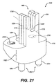
- the instrument 100 as described in FIGS. 13-18 include only two holes being formed in the scapula 40 and appreciated that the glenoid component 20 of FIGS. 4-8 include four first pegs 34. It should be appreciated that the glenoid component 20 may include only one first peg 34 as shown in FIG. 19 or alternatively the first drill guide of claim 15 or the second drill guide 196 of FIG. 18, may be include additional bushing for receiving a drill for preparing the holes for receiving the additional pegs for the glenoid component 20.
- the cutting guide 156 of the instrument set 101 includes a base 176, which defines mounting hole 194 for passing the mounting screw 190 therethrough.
- Base 176 may further include a first threaded opening 216 for use with the right shoulder and a second threaded opening 218 with use with a left shoulder. The use of the two threaded holes 216 and 218 permits the cutting guide 156 to be symmetrical and therefore to be useable for both the right shoulder and the left shoulder.
- Base 176 further includes the mounting surface 182 which, as is shown in FIGS. 20-21, may be convex.
- the cutting guide 156 further includes the guiding feature 160 as well as the locating feature 162.
- the guiding feature 160 may include the first post 174 in which the bearing or trunnion 172 is formed.
- the guiding feature 162 may include a second post 220 extending spaced from and parallel to the first post 174.
- the second post 220 includes a second post bearing 222, which is parallel and spaced from the first bearing 172. It should be appreciated that a solitary post 174 may be sufficient if the post 174 has a bearing of sufficient width to adequately support the cutter 158 (see FIG. 16).
- the locating feature 162 may be in the form of, as shown in FIGS. 20 and 21, the mounting surface 182, as well as, the additional features in the form of, for example, the first peg hole alignment 184. It should be appreciated that the locating feature 162 may further include a second peg hole alignment pin 224 spaced from the first peg hole alignment pin 184. Pin 224 also extends from the mounting surface 182.
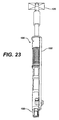
- the cutting tool assembly 226 includes sheath or housing 168.
- the sheath 168 is generally cylindrical and hollow.
- a milling cutter body 228 is rotatably fitted within the sheath 168.
- the milling cutter 158 extends from distal end 230 of the body 228.
- the body 228 is slideably positioned along the shaft portion 232 of stem 234.
- the body 228 is at least partially hollow for receiving the shaft portion 232 of the stem 234.
- a spring 236 may be utilize to urge sheath 168 distally in the direction of arrow 238 to protect the milling cutter 158.
- the spring 236 cooperates with shoulder 240 to urge the sheath 168 in the direction of arrow 238.
- a connector 242 is positioned proximally on the stem 234 for cooperation with a tool, for example, a drill 106 to drive or rotate the milling cutter 158.
- the milling cutter 158 may have any suitable shape and may, as shown in FIGS. 22-25, include a plurality of flutes 244, which include cutting edges 246. Any number of plurality of flutes 244 may be utilized. For example and is shown in FIGS. 22-25, four equally spaced apart flutes 244 may be utilized. As shown in FIGS. 22-25, the milling cutter 158 may include internal openings 248 to provide a collection point for the machined bone.
- the cutting tool assembly 226 may be secured to the bearing 172 of the cutting guide 156 (see FIG. 16) in any suitable manner.
- the cutting tool assembly 226 is supported by pivoting support 250.
- the pivoting support 250 may have any suitable size and shape and may as shown in FIGS. 24 and 25 include a first pintle 252 extending from the sheath 168 adjacent to cutter 158.
- the support 250 may also include and a second pintle 254 opposed to the first pintle 252, and also extending from the cylinder 168.
- the first pintle 252 or the second pintle 254 or both may include a stop ring to assist in the support of the cutting tool assembly 226.
- the cutting tool assembly includes a stop ring 256 extending from pintle 254. At least one of the pintles, 252 or 254 may be utilized to cooperate with the bearings 172 to permit the pivoting of the cutting tool assembly 222 about axis 178 as shown in FIG. 16.
- Cutting guide 356 is similar to the cutting guide 156 of FIGS. 20 and 21.
- the cutting guide 356 includes a base 376.
- the base 376 defines convex mounting surface 382.
- the cutting guide 356 includes a locating feature 362 including, for example, mounting surface 382 as well as pegs 384 extending from the mounting surface 382.
- the cutting guide 356 further includes a guiding feature 360 in the form of, for example, first support or post 374 and second or outward support 320.
- the supports 374 and 320 are utilized to define inboard bearing 372 and outboard bearing 322.
- the bearings 372 and 320 define longitudinal axis 378 about which the tool assembly rotates.
- the cutting guide 356 includes both outboard and inboard bearings 372 and outboard bearing 322 that are spaced further from each other than the bearings 222 and 172 of the cutting guide 156.
- the bearings 372 and 322 of the cutting guide 356, unlike the bearings of the cutting guide 156, are spaced apart so that the sheath 168 of the cutting tool assembly 156 may be positioned between the inward post 274 and the outboard post 320. Since the cutting tool assembly 226 is positioned between the post 274 and the post 320, the base 276 includes a central opening or aperture 330 through which the sheath 168 may rotate and through which the cutter 158 may pass.
- the cutting guide 356 of FIG. 26 includes a mounting hole 342 as well as a pair of spaced apart handle holes 316 for use with the left or right hand shoulder.
- the kit 100 includes a first portion tool or end mill 110 as well as a exterior pocket preparing instrument 150.
- the first portion tool or mill 110 may include a stem or shank 114 to which cutter 112 extends.
- a central opening 116 may extend through the cutter 112 and the stem 114.
- the exterior pocket preparing instrument 150 may include a cutting guide 156 as well as cutting tool assembly 226.
- the cutting tool assembly 226 may include a sheath 168 within, which rotatable tool 158 rotates.
- the cutting guide 156 may include a base 176, which defines locating surface 182.
- Cutting guide 156 includes a first feature or guiding feature 160, which include a bearing 172 for supporting the cutting tool assembly 226.
- the bearing 172 is supported by a post 174 extending from the base 176.
- the cutting guide 176 further includes a second feature or positioning feature 162.
- the positioning feature 162 may include the locating surface 182 as well as, for example, protrusions in the form of, for example, pin 184.
- a handle 180 may be utilized to guide the cutting guide 156 into position unto the glenoid.
- the instrument set 101 may include a pin 100 for use with positioning the end mill 110.
- the instrument 110 may further include a drill guide 130 for preparing a first peg opening 146.
- the first drill guide 130 may include a base 132, which defines an opening 136 for receiving the alignment pin 100 as well as a support surface 134.
- a drill 144 may be utilized with the first drill guide 130 and pass there through.
- a handle 140 may be utilize to properly position the first drill guide 130.
- the instrument kit 101 may further include an additional drill guide 196.
- the drill guide 196 may be utilized for preparing the second peg hole 198.
- the second drill guide 196 may include a base 202 from which second peg hole alignment pin 208 extends.
- the base 202 is adapted for receiving and guiding drill 200 to form second peg hole 198.
- Drill guide 196 may include a handle 204 for positioning the guide 196.
- the instrument kit 100 may further include an additional drill guide 390 for preparing additional peg holes for the glenoid component.
- the instrument kit 100 may include drill guide 300 having a base 392 including for example, first opening 394 and second opening 396 for receiving a drill to prepare additional peg holes.
- Drill guide 390 may include a handle 398 for assisting in positioning the guide 390.
- humeral prosthesis 400 is shown for use with a glenoid pocket 410 prepared by the instruments of the present invention.
- the prosthesis assembly 400 includes a humeral prosthesis 408 positioned on humerus 404.
- the humeral prosthesis 408 includes a head 406 extending from the humeral stem 402.
- the humeral stem 402 and humeral head 406 form humeral prosthesis 408.
- Glenoid component 20 cooperates with head 406 of the humeral prosthesis 408.
- the glenoid component 20 is positioned in prepared pocket 410 including prepared surface 122 as well as mounting pocket 152 formed on scapula 40 with the instruments of the present inventions.
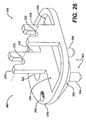
- the cutting tool assembly 526 includes a sheath or housing 568.
- the sheath 568 is generally cylindrical and hollow.
- a milling cutter body 558 is rotatably fixed within the sheath 168.
- the milling cutter 558 extends from the distal end 530 of the body 528.
- the body 528 is slidably engagable with stem 534.
- the body 528 defines a female cutter connection 594, which engages with male cutter connection 592 formed on stem 534.
- the male cutter connection 592 may include a groove 596, which mates with a helical spring 598 positioned in the female cutter connection 594 of the milling cutter body 528, the sheath 568, and the stem 534 may be made of a metal. If made of a metal, the metal may be a cobalt chromium alloy, a stainless alloy, or a titanium alloy.
- the bushing 590 may also be made of any suitable, durable material but preferably is made of a material that provide a bearing function for the cutting tool assembly.
- the bushing 590 may be made of a plastic, for example, acetal copolymer.
- the milling cutter 558 may have any suitable shape and may include a plurality of flutes 544 including the cutting edges 546. Any number of plurality of flutes 544 may be utilized. For example, and is shown in FIG. 29-31, four equally spaced apart flutes 544 may be utilized.
- the cutting tool assembly 526 may include a connector 542 for connection with the driving tool, for example, a power drill 106.
- the stem 534 may have any suitable shape and may include a shaft portion 532 positioned between the connector 542 and male connector 592.
- a collar 588 may be positioned between the shaft 532 and the male connection 592. The collar 588 serves a axial seat for the bushing 590.
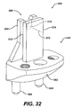
- the cutting guide 556 is similar to the cutting guide 156 of FIGS. 20-21.
- the cutting guide 556 is designed for use with the cutting tool assembly 526 of FIG. 29-31.
- the cutting guide 556 includes a base 576.
- the base 576 defines convex mounting surface 582.
- the cutting guide 556 includes a locating feature 562 including, for example, mounting surface 582 as well as pegs 584 extending from the mounting surface 582.
- the cutting guide 556 further includes a guiding feature 560 in the form of, for example, a first support or post 574 and a second post or bearing 520.
- the support 574 and 520 are utilized to define bearing 572 and stop 522.
- the bearing 520 defines longitudinal axis 578 about which the tool assembly rotates.
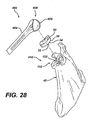
- cutting assembly mounting mechanism 555 is shown.
- the cutting assembly mounting mechanism 555 cooperates with the guiding feature 560 of the cutting guide 556 of FIG. 32.
- the cutter assembly mounting mechanism 555 includes a stop ring 552 extending outwardly from pintle 554.
- the pintle 554 is designed to rotate on bearing on trunnion 572 of guiding feature 560 of the cutting guide 556 of FIG. 32.
- the stop ring 552 is positioned between stop 522 of the first post 574 and the second post 520.
- the milling cutting body 528, the sheath 568, and the stem 534 may be made by an suitable, durable material.
- the milling cutter body 528, sheath 568 and stem 534 may be made of a metal, for example, a cobalt chromium alloy, a stainless steel alloy, or a titanium alloy.
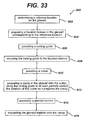
- a method 600 of performing shoulder arthoplasty includes a first step 602 of determining a preference location on the glenoid and a second step 604 and preparing a location feature in the glenoid corresponding to reference location.
- the method 600 further includes a seventh step 614 of providing a glenoid implant and an eighth step 616 of implanting the glenoid implant into the cavity.
- the method 600 further includes a third step 606 of providing a cutting guide and a fourth step 608 of securing the cutting to the location feature.
- the method 600 further includes a fifth step 610 of providing a cutter and a sixth step 612 of preparing a cavity with the glenoid cutter and using the cutter guide to at least partially control the position of the cutter as prepares the cavity.
- FIG. 34 shows an instrument set 700 which is similar to the instrument set 101 of FIGS. 13-25 and also similar to the instrument set 500 of FIGS. 29-32.
- the instrument set 700 includes a cutting guide 756 similar to the cutting guide 556 of FIG.32.
- the instrument 700 further includes a cutting tool assembly 726 for cooperation with the cutting guide 756.
- the cutting tool assembly 726 is generally similar to the cutting tool assembly 526 of FIGS. 29-31.
- the instrument set 700 shown in FIG. 34 is adapted for use in preparing mounting pockets 752 and 753 on the tibia 701.
- the mounting pocket 752 and 753 may be used to receive a portion of a unitary tibial (not shown), tray as part of a knee prosthesis (not shown), or the mounting pocket 752 may be used to receive a medial partial tibial component (not shown)of a partial knee prosthesis (not shown).
- the mounting pocket 753 may be adapted for receiving a lateral partial tibial component of the partial knee prosthesis.
- the cutting tool assembly 726 is mountable on the cutting guide 756.
- the cutting guide 756 may include a base 776 including surface ???? 782 for cooperation with prepared surface 751 of the tibia 701.
- the prepared surface 751 may be prepared by tools similar to that of the instrument set 101 of FIGS.13-25.
- Supports in the forms of bearing 720 and post 774 may extend from the base 776.
- the cutting tool assembly 726 may include a cylindrical body 768 which is hollow.
- a tool cutter 758 may be rotatably fitted within the cylinder 768.
- the tool cutter 758 may be connected to, for example, power source 706.
- the power source 706 may be in the form of, for example, a power drill.
- a pintle 754 may extend from the cylinder 768.
- the pintle 754 rests on trunnion 772 formed on the bearing 720.
- a stop ring 752 may extend outwardly from the pintle 754.
- the stop ring 752 is constrained between bearing 720 and post 774 of the cutting guide 756.
- the stop ring 754 and the pintle 754 comprise the mounting mechanism 755 of the cutting tool assembly 756.
- the mounting mechanism 755 of the cutting tool assembly 726 cooperates with first feature 760 of the cutting guide 756.
- the first feature 760 includes the bearing 720 and the post 774.
- the cutting guide 756 may be positioned in a post position on the tibia 701 opposed to that position as shown in FIG. 34. In such a second position the cutting tool 758, as shown in phantom, in positioned over the second mounting pocket 753. By doing so, the cutting tool assembly 726 and the cutting guide 756 may be used to prepare the first mounting pocket 752 as well as the second mounting pocket 753 of the tibia 701.
- the instrument set of the present invention may be utilized to prepare pockets or portions of a joint within the body to prepare a surface for mounting a prosthesis.
- the instrument set of the present invention may be utilized to prepare a surface on the femur, the humerus, the ulna, the radius, or the tibia.
Landscapes
- Health & Medical Sciences (AREA)
- Life Sciences & Earth Sciences (AREA)
- Orthopedic Medicine & Surgery (AREA)
- Animal Behavior & Ethology (AREA)
- General Health & Medical Sciences (AREA)
- Engineering & Computer Science (AREA)
- Biomedical Technology (AREA)
- Heart & Thoracic Surgery (AREA)
- Veterinary Medicine (AREA)
- Oral & Maxillofacial Surgery (AREA)
- Public Health (AREA)
- Surgery (AREA)
- Transplantation (AREA)
- Cardiology (AREA)
- Vascular Medicine (AREA)
- Dentistry (AREA)
- Nuclear Medicine, Radiotherapy & Molecular Imaging (AREA)
- Medical Informatics (AREA)
- Molecular Biology (AREA)
- Physical Education & Sports Medicine (AREA)
- Prostheses (AREA)
- Surgical Instruments (AREA)
- Materials For Medical Uses (AREA)
Abstract
Description
- The present invention relates generally to the field of orthopaedics, and more particularly, to an implant for use in arthroplasty.
- During the lifetime of a patient, it may be necessary to perform a total shoulder replacement procedure on the patient as a result of, for example, disease or trauma. In a total shoulder replacement procedure, a humeral component having a head portion is utilized to replace the natural head portion of the arm bone or humerus. The humeral component may include an elongated intramedullary stem which is utilized to secure the humeral component to the patient's humerus. In such a total shoulder replacement procedure, the natural glenoid surface of the scapula is resurfaced or otherwise replaced with a glenoid component that provides a bearing surface for the head portion of the humeral component. The humeral component may be made without a stem or with a short stem.
- As alluded to above, the need for a shoulder replacement procedure may be created by the presence of any one of a number of conditions. One such condition is the deterioration of the patient's scapula in the glenoid surface as a result of, for example, glenohumeral arthritis. In such a condition, erosion of the patient's scapula may be observed. The erosion may be asymmetric, anterior or posterior. Posterior erosion of on the glenoid surface is particularly common. Such erosion of the scapula renders treatment difficult, if not impossible, with a conventional glenoid prosthesis.
- In order to treat a condition in which a portion of the scapula has been eroded, a number of glenoid prostheses have heretofore been designed. Such glenoid prostheses, known generally as augmented glenoid prostheses, have a posterior edge that is thicker than the corresponding anterior edge.
- In FIG. 1, a heretofore-designed augmented
glenoid component 1 is shown. Theglenoid component 1 has ametallic backing component 5 andplastic insert 4. - The thickness of the
metallic backing component 5 gradually increases from an anterior edge to a posterior edge thereof. The arcuate-shapedmedial surface 2 may over time lead to loosening of the augmentedglenoid component 1, thereby potentially necessitating additional surgical procedures to replace or reseat thecomponent 1. Further, due to the configuration of themedial surface 2, a relatively high shear load is created along the implant-to-bone interface when thecomponent 1 is implanted. The presence of a high shear load along the implant-to-bone interface tends to also cause loosening of thecomponent 1 over a period of time. Post-operative loosening is the largest cause of failures of implanted glenoid components. - As shown in FIG. 1, the metal backing may include additional features in the form of, for example,
pegs 6 and centre peg 7 to provide additional support of the glenoid implant on thescapula 3. - Another known augmented
glenoid component 8 is shown in FIG. 2. Theglenoid component 8 has a single componentplastic body 9A. The thickness of theplastic body 9A gradually increases from ananterior edge 8A to aposterior edge 8B thereof thereby creating a relatively smooth, arcuate-shapedmedial surface 10 from which a number of posts or pegs 8 extend. The design of this augmentedglenoid component 8, however, suffers from at least the same drawbacks as theglenoid component 1. - Another known augmented
glenoid component 11 is shown in FIG. 3. Theglenoid component 11 also has a single componentplastic body 11A. The thickness of theplastic body 9B gradually increases from ananterior edge 11A to aposterior edge 11B thereof thereby creating a relatively smoothmedial surface 11C from which akeel 12 extends. The design of this augmentedglenoid component 11, however, suffers from at least the same drawbacks as theglenoid components - Attempts to correct the four mentioned problems with posterior glenoid wear have included the invention of an augmented glenoid component with a step support face with the step support face being posterior. Such an augmented glenoid component is much more fully disclosed in US-6699289.
- The augmented glenoid component disclosed in US-6699289 requires a stepped pocket or locating surface for the augmented glenoid component. Such a stepped surface is very difficult to create. Certain processes for preparing the glenoid fossa for such a component can consist merely of hand or power tools, which are manually guided to prepare the cavity for receiving the augmented glenoid component.
- In one aspect, the invention provides an instrument for preparing a surface of a joint, the surface adapted for receiving a glenoid component having a feature closely conforming to the glenoid surface, the prosthetic component providing a bearing surface for a portion of a long bone, the instrument comprising:
- a guide having a first feature and a second feature; and
- a tool for cooperation with the first feature for preparing the surface, the first feature adapted to at least partially control the position of the tool as it prepares the surface, the second feature adapted to assist in positioning of the guide with respect to the joint.
- In another aspect, the invention provides an instrument for preparing a feature on a scapula, the feature adapted for receiving an augmented glenoid component for providing a bearing surface for a head portion of a humerus, the instrument comprising:
- a guide defining a guiding feature and a locating feature; and
- a tool for cooperation with the guiding feature for preparing the glenoid surface, the guiding feature adapted to at least partially guiding the tool as it prepares the feature, the locating feature adapted to assist in locating the guide with respect to the scapula.
- ln a further aspect, the invention provides an instrument kit for preparing a glenoid of a scapula, the glenoid adapted for receiving a glenoid component having a feature closely conforming to the glenoid, the glenoid component providing a bearing surface for a head portion of a humerus, the instrument kit comprising:
- a first portion tool for preparing a first portion of the glenoid of a scapula; and
- a second portion tool assembly for preparing a second portion of the glenoid of a scapula, a substantial portion of the second portion being spaced from the first portion.
- Instruments provided by the present invention can be used in a method for performing arthroplasty on a glenoid comprising the steps of:
- determining a reference location on the glenoid;
- preparing a location feature in the glenoid corresponding to the reference location;
- providing an cutting guide;
- securing the cutting guide to the location feature;
- providing a cutter;
- preparing a cavity in the glenoid with the cutter, using the cutting guide to at least partially control the position of the cutter as it prepares the cavity;
- providing a glenoid implant; and
- implanting the glenoid implant onto the cavity.
- Instruments provided by the present invention can produce a geometry of a complex nature for an implant surface when irregular bone loss has occurred and an augmented implant component is advised.
- According to the present invention, a device and technique are provided by which the surgeon can mill the glenoid surface in a bone preserving fashion. A step is created in the glenoid fossa that replicates the backside surface of an augmented step glenoid implant such as disclosed in US-6699289. The instrumentation may include a rotating mill with a sleeve that has a fixed pivoting axis to create a cylindrical shape in the posterior aspect of the eroded glenoid fossa. This mill, with the pivoting axis, engages a guide that prescribes or limits the proper depth for the step. This guide can be instructed in many ways that permit the mill to plunge into the posterior glenoid and then pivot on its axis while milling the bone. The device is used to create a cylindrical step in the glenoid so that the glenoid implant can be fully supported.
- This step glenoid of the glenoid implant and underlying bony support permits forces to be transmitted to the scapula in a manner that greatly reduces sheer. By reducing the risk of high sheer it is believed the implant will be more stable and less likely to result in loosening and failure.
- According to the present invention, two distinct devices may work in concert to create a desired step geometry for the augmented step glenoid implant. The first of these devices is a milling device with a cutting head that embodies a specific shape matching the cross-sectional shape of the step portion of glenoid implant. The milling device is connected to a shaft for attachment to a power driven device such as a drill. Around the cutting head is a sleeve that has a pivoting axis at a specific position on the shaft such that when the cutting head is fully extended from the shaft, the cutting head is at a fixed known position relative to the pivoting axis. This permits a reproducible cylindrical geometry to be milled into the bone. Alternatively, the cutting head and sleeve may not move relative to each other and the cutting head may be in a fixed relationship with the pivoting axis on the sleeve.
- The other device is a positioning jig that permits the surgeon to accurately place in a reproducible manner the milling device such that the mill removes only the bone necessary to match a glenoid implant to the patients condition. This jig defines a depth of cut as well as accurately positioning the cutter so that the device mills the bone longitudinally along the axis of the glenoid fossa. Only the posterior eroded bone is resurfaced to a defined shape matching the implant. The jig may accomplish this task while only permitting the rotation of the pivoting axis defined on the mill sleeve. The translation of the mill device may be permitted in a medial lateral direction. An end stop defines the depth of the step relative to the reamed anterior portion of the glenoid fossa.
- The two devices function together to create a reproducible geometry on the glenoid where posterior bone loss exists permitting the use of a posterior augmented glenoid implant.
- According to one embodiment of the present invention, there is provided an instrument for preparing a surface of a joint. The surface is adapted for receiving a prosthesis component having a feature closely conforming to the surface. The prosthesis component provides a bearing surface for a portion of a long bone. The instrument includes a guide having a first feature and a second feature and a tool. The tool is used for cooperation with the first feature for preparing the surface. The first feature is adapted to at least partially control the position of the tool as it prepares the surface. The second feature is adapted to assist in positioning of the guide with respect to the joint.
- According to another embodiment of the present invention there is provided an instrument for preparing a feature on a scapula. The feature is adapted for receiving an augmented glenoid component for providing a bearing surface for a head portion of a humerus. The instrument includes a guide defining a guiding feature and a locating feature and a tool. The tool is used for cooperation with the guiding feature for preparing the feature. The guiding feature is adapted to at least partially guiding the tool as it prepares the glenoid surface. The locating feature is adapted to assist in locating the guide with respect to the scapula.
- According to still another embodiment of the present invention there is provided an instrument kit for use in preparing a glenoid of a scapula. The glenoid is adapted for receiving a glenoid component having a feature closely conforming to the glenoid. The glenoid component provides a bearing surface for a head portion of a humerus. The instrument kit includes a first portion tool for preparing a first portion of the glenoid of a scapula and a second portion tool assembly for preparing a second portion of the glenoid of a scapula. A substantial portion of the second portion tool is spaced from the first portion.
- According to a further embodiment of the present invention, there is provided a method for performing arthroplasty on a glenoid. The method includes the steps of determining a reference location on the glenoid and preparing a location feature in the glenoid corresponding to the reference location. The method also includes the steps of providing a cutting guide, securing the cutting guide to the location feature, and providing a cutter. The method also includes the steps of preparing a cavity in the glenoid with the cutter, using the cutting guide to at least partially control the position of the cutter as it prepares the cavity. The method further includes the steps of providing a glenoid implant and implanting the glenoid implant onto the cavity.
- The technical advantages of the present invention include the ability to reproduce the complex geometry in a glenoid to replicate and support a posterior augmented glenoid. For example, according to one aspect of the present invention, an instrument kit for preparing a glenoid scapula is provided. The glenoid is adapted for receiving a glenoid component having a feature closely forming to the glenoid. The glenoid component provides a bearing surface for a head portion of a humerus.
- The instrument kit includes a first portion tool for preparing a first portion of the glenoid and a second portion of the glenoid. A substantial portion of the second portion is spaced from the first portion. The second portion tool assembly includes a guide having a first feature and a second feature and a second portion tool. The second portion tool cooperates with a first feature for preparing the second portion of the glenoid. The first feature is adapted to at least partially to control the position of the second portion of the tool as prepares the second glenoid surface. The guide and tools provides a reproducible complex geometry. Thus, the present invention provides for a reproducible complex geometry and a glenoid to replicate and support the posterior augmented glenoid.
- The technical advantages of the present invention, further include the ability to produce a support surface to support a glenoid that transmits forces normally to the articulating surface. The normal support results in less shear, greater stability and less likelihood of the glenoid prosthesis to loosen. For example, according to another aspect of the present invention, an instrument kit is provided with a first portion tool for preparing a first portion of the glenoid and a second portion tool for preparing a second portion of the glenoid. The second portion tool cooperates with the first feature prepared by the first portion tool. The guide includes a base and a restraining component to guide the tool in a position normal to the articulating surface. Thus, the present invention provides for a support surface to support a glenoid that transmits forces normally to the articulating surface.
- The technical advantages of the present invention further include the ability to remove only bone that is necessary to match the implant. For example, according to yet another aspect of the present invention, an instrument kit is provided for preparing a glenoid of a scapula including a first portion tool for preparing a first portion of the glenoid and a second portion tool assembly. The second portion tool assembly is supported by the surface prepared by the first portion tool. The second portion tool assembly includes a rotatable tool and a cylindrical tube surrounding the tool. The cylindrical tube is pivotally attached to a bearing to provide a shape similar to that of the posterior augmented portion of the posterior augmented glenoid. Thus, the present invention provides for the removal of only the bone necessary to match the implant.
- The technical advantages of the present invention, further include the ability of the jig to define the depth of cut for preparing the glenoid surface. For example, according to one aspect of the present invention, an instrument kit is provided including a first portion tool for preparing a first portion and a second portion tool assembly including a guide supported by the surface prepared by the first portion tool and a second portion tool for cooperating with the guide. The guide and the second portion tool act in concert to define the depth of cut. Thus, the present invention provides for a jig that can define the depth of cut.
- The technical advantages of the present invention include the ability of the instrument to accurately position the cutter. For example, according to yet another aspect of the present invention, an instrument kit is provided with a first portion tool and a second portion tool assembly including a guide supported by the surface prepared by the first portion tool. The second portion tool assembly includes a guide having a base and a restraining component. The restraining component restrains the second portion tool to provide for an accurate position of the cutter. Thus, the present invention provides for a guide for accurately positioning the cutter.
- The technical advantages of the present invention also include the ability of the instrument of the present invention to be used for right and left hand shoulders. For example according to a further of the present invention, the instrument kit includes a guide, which may be symmetrically designed. By being symmetrically designed, the guide may be used for both right and left-hand shoulders. Thus, the present invention, provides for an instrument that can be used for right and left hand shoulders.
- The technical advantages of the present invention further include the ability of the instrument to be used for all sizes and shapes of glenoid implants. For example, according to yet another aspect of the present invention, the instrument includes a first portion tool for preparing a first portion of the glenoid and a second portion tool including a guide being supported by the surface prepared by the first portion tool and a second portion tool to be constrained by the guide. The guide may be modular or may include an internal component or bushing to provide for different diameters of the second portion tool. Similarly, the first portion tool may be provided with different sizes to provide for a variety of glenoid implants. Thus, the present invention provides for an instrument that may be used for all sizes of glenoid implants.
- Other technical advantages of the present invention will be readily apparent to one skilled in the art from the following figures, descriptions and claims.
- Embodiments of the invention will now be described by way of example with reference to the accompanying drawings, in which:
- FIG. 1 is a side sectional view of a prior art augmented glenoid component;
- FIG. 2 is a side sectional view of another prior art augmented glenoid component;
- FIG. 3 is a side sectional view of another prior art augmented glenoid component;
- FIG. 4 is a perspective view showing an augmented glenoid component for use in a cavity prepared by the cutting tool of the present invention;
- FIG. 5 is another perspective view of the augmented glenoid component of FIG. 4;
- FIG. 6 is an end view of the augmented glenoid component of FIG. 4;
- FIG. 7 is an bottom view of the augmented glenoid component of FIG. 4;
- FIG. 8 is an side view of the augmented glenoid component of FIG. 4;
- FIG. 9 is a side view partially in cross section of a natural glenoid fossa with posterior erosion;
- FIG. 10 is a side view partially in cross section of a natural glenoid fossa with a portion machined for receiving a prior art glenoid component;
- FIG. 11 is a side sectional view of a prior art augmented glenoid component in position on a prepared glenoid fossa;
- FIG. 12 is a side view partially in cross section of another natural glenoid fossa with posterior erosion;
- FIG. 13 is a side view partially in cross section of the natural glenoid fossa with posterior erosion of FIG. 12 with an alignment pin in position in the glenoid;
- FIG. 14 is a side view partially in cross section of the natural glenoid fossa with posterior erosion with an alignment pin of FIG. 13 showing an end mill in contact with the glenoid fossa preparing a surface according to an embodiment of the present invention;
- FIG. 15 is a side view partially in cross section of the glenoid fossa with posterior erosion showing the surface prepared by the end mill of FIG. 14 and showing a drill guide for preparing a glenoid component peg hole according to an embodiment of the present invention in position on the surface prepared by the end mill of FIG. 14;
- FIG. 16 is a side view partially in cross section of the glenoid fossa with posterior erosion showing cutting guide for use in preparing a mounting pocket for a posterior augmented glenoid component with the drill guide aligned to the peg hole prepared by the drill guide of FIG. 15 according to an embodiment of the present invention;
- FIG. 17 is an end view of the cutting guide and glenoid fossa of FIG. 16;
- FIG. 18 is a side view partially in cross section of the glenoid fossa with posterior erosion showing the mounting pocket prepared using the cutting guide of FIG. 16 and showing a second drill guide for preparing a second glenoid component peg hole according to an embodiment of the present invention in position on the surface prepared by the end mill of FIG. 9;
- FIG. 19 is an exploded side view partially in cross section of the glenoid fossa with posterior erosion showing the mounting pocket prepared using the cutting guide of FIG. 16 and two peg holes prepared using the drill guides of FIGS. 15 and 17 and showing a glenoid component in position above the prepared surface according to an embodiment of the present invention;
- FIG. 20 is a perspective view of the base of the cutting guide of FIG. 16 according to an embodiment of the present invention;
- FIG. 21 is another perspective view of the base of FIG. 20;
- FIG. 22 is a perspective view of a cutting tool for use in preparing the mounting pocket for the posterior augmented glenoid component of FIG. 19 and a cut-away partial perspective view of the restraining component of the cutting guide for use with the base of FIG. 20 to form the cutting guide of FIG. 16 according to an embodiment of the present invention;
- FIG. 23 is another perspective view of the cutting tool and restraining component of FIG. 22 according to an embodiment of the present invention;
- FIG. 24 is yet another perspective view of the cutting tool and restraining component of FIG. 22 according to an embodiment of the present invention showing the cutting tool in the retracted position;
- FIG. 25 is still another perspective view of the cutting tool and restraining component of FIG. 22 according to an embodiment of the present invention showing the cutting tool in the extended position;
- FIG. 26 is a perspective view of another embodiment of a base for the cutting guide of FIG. 16 with an outboard support;
- FIG. 27 is a plan view partially in cross section of a kit for use in performing shoulder arthroplasty in accordance with another embodiment of the present invention;
- FIG. 28 is an exploded perspective view of glenoid vault of a scapula, a humerus, and an augmented glenoid for use in the cavity of a glenoid prepared with the instruments of the present invention; and
- FIG. 29 is a perspective view of a cutting tool assembly according to another embodiment of the present invention;
- FIG. 30 is a perspective view of the cutting total assembly of FIG. 29;
- FIG. 31 is an exploded perspective view of the cutting tool assembly of FIG. 29;
- FIG. 32 is a perspective view of a cutting guide for use with the cutting assembly tool of FIG. 29 is accordance to an embodiment of the present invention;
- FIG. 33 is a flow chart of a method for performing shoulder arthroplasty in accordance with yet another embodiment of the present invention; and
- FIG. 34 is plan view of a cutting tool assembly for use on a tibia for preparing a tibia for a knee prosthesis according to another embodiment of the present invention.
- Referring to the drawings, FIG. 4-8 show a
glenoid component 20 which may be used in a cavity prepared by the instrument of the present invention. Theglenoid component 20 is in the form of an augmented glenoid and may, as shown in FIG. 4-8 include a buttress22 separating a first mountingsurface 24 from a second mountingsurface 26. Theglenoid component 20 may include an articulatingsurface 28 positioned opposed to the mountingsurfaces - The augmented
glenoid component 20 may include additional features to help secure theglenoid component 20 to the scapula. For example, the first mountingsurface 24 may include first pegs 30 extending from the mountingsurface 24 as well as acentral peg 32. The second mountingsurface 26 may also includepegs 30 for extending from the mountingsurface 26. The second mounting surface and the articulatingsurface 28 define a posterior augment 36 positioned between the mountingsurface 26 and the articulatingsurface 28. The posterior augment 36 provides support for the posterior erosion of the glenoid. - Referring now to FIG. 9, natural glenoid 38 of
scapula 40 is shown. The natural glenoid 38 includes aportion 3 of thescapula 40 with asurface 42 describing posterior erosion. - Referring now to FIG. 10, the
scapula 40 is shown with a first milledsurface 44 extracted from the natural glenoid 38 and apocket 46 machined with the instruments of the present invention shown removing theposterior erosion surface 42. The machinedglenoid surface 44 and thepocket 46 may be prepared utilizing the instruments of the present invention. - Referring now to FIG. 11, the
glenoid component 20 of FIGS. 4-8 is shown in position above on thepocket 46 andglenoid surfaces 44 prepared by the instruments of the present invention. As can be shown in FIG. 11, the force F from the patient may be supported by resistance forces R1 and R2 extending from the preparedglenoid surface 44 and thepocket 46 respectively. As can be seen in FIG. 11, the forces R1, R2, and F are all collinear. Thus, the instrument of the present invention provides for a posterior augmented glenoid 20, which provides for normal forces and minimizes shear forces to provide for less shear and a more stable glenoid implant that is less likely to loosen during use. - Referring now to FIG. 12, a glenoid fossa of a
scapula 40 is shown. Theglenoid fossa 38 includes a posteriorly erodedsurface 42 with the healthy glenoid surface shown in phantom assurface 48. - According to the present invention and referring now to FIG. 13-19, instrumentation and a corresponding method are shown for preparing an implant support surface for a glenoid implant.
- According to the present invention and referring now to FIG. 13, an
alignment pin 100 is shown in position in thescapula 40. Thealignment pin 100 may include, for example, a point or cuttingedge 102 for use in cutting bone in the installation process of thealignment pin 100. Thealignment pin 100 may further includeexternal threads 104 for assisting in the insertion of thealignment pin 100. Thealignment pin 100 may be a part of aninstrument set 101. - The
alignment pin 100 may be positioned in theglenoid fossa 38 of thescapula 40 in any suitable manner. For example, thealignment pin 100 may be manually inserted. The alignment pin may be inserted by hand or with the use of, for example, a power tool, for example, adrill 106. Thealignment pin 100 may be positioned manually or may as shown in FIG. 13, may be guided by, for example, guide 108 that is positioned againstouter surface 110 of thescapula 40. It should be appreciated that thealignment pin 100 may be inserted using diagnostic techniques such that using a fluoroscope or may alternatively be positioned using computer aided surgical devices. For example, and as shown in FIG. 13 thealignment pin 100 may be centrally positioned in theglenoid fossa 38. Theguide 108 and thedrill 106 may also be part of the instrument set 101. - According to the present invention and referring now to FIG. 14, a
first portion tool 110 in the form of, for example, an end mill is shown. Theend mill 110 includes acutter 112 to whichshank 114 is attached. Theend mill 110 includes thecentral opening 116. thecentral opening 116 is sized for sliding engagement withalignment pin 100. Theend mill 110 may also be part of the instrument set 101. - As shown in FIG. 14, the
end mill 110 is positioned above theglenoid fossa 38 and thealignment pin 100 is engaged withopening 116 to advance theend mill 110 in the direction ofarrow 118 until cuttingedge 120 of thecutter 112 engages with theglenoid fossa 38. Thecutting edge 120 is utilized to formfirst portion 122 ofprepared surface 124. Thefirst portion 122 of theprepared surface 124 may have any shape. For example, and as is shown in FIG. 14, thefirst portion 122 of theprepared surface 124 may have a shape defined by cuttingedge 120 of thecutter 112. While thecutter 112 may have any suitable shape, for simplicity and is shown in FIG. 14, thecutter 112 has acutting edge 120 defined by a radius R extending from origin 126. Thecutting edge 120 thus is convex and may be, as shown in FIG. 14, a portion of a sphere. When machined by thecutting edge 120 of thecutter 112 of FIG. 14, thefirst portion 122 is generally concaved. - The
end mill 110 may be manually rotated in the direction ofarrow 128 by any suitable method. For example, theend mill 110 may be manually rotated or rotated by a tool in the form of, for example, adrill 106. Preferably and is shown in FIG. 14, theglenoid fossa 38 of thescapula 20 is machined until the entireconcave portion 122 is a prepared surface. - According to the present invention and referring now to FIG. 15, a guide in the form of
first drill guide 130 is shown as part of the instrument set 101 of the present invention. Thefirst drill guide 130 is utilized after the concavefirst portion 122 has been prepared by thefirst portion tool 110 of FIG. 14. - The
first drill guide 130 includes a base 132 having acontact surface 134 for contact with theprepared surface 122 of thescapula 40. The locatingsurface 134 preferably has the shape closely conform with theprepared surface 122. Thus, thecontact surface 134 is preferably generally convex. - As shown in FIG. 15, the
first drill guide 130 further may include anopening 136 for cooperation withalignment pin 101. Theopening 136 is sized for slideably fitting thealignment pin 100.First drill guide 130 is installed onto thescapula 40 by advancing thefirst drill guide 130 in the direction ofarrow 138 until theopening 136 of thebase 132 is in alignment withalignment pin 100 with which thefirst drill guide 130 is thereby aligned. Thealignment pin 100 is slidably fitted to opening 136 of thefirst drill guide 130 . Thefirst opening 136 of thedrill guide 136 is then mated with thealignment pin 100 untilconvex surface 134 of thebase 132 is seated against theprepared surface 122 of thescapula 40. In this position thefirst drill guide 130 is seated in location for its use. - The
first drill guide 130 further includes a guidingfeature 140 in the form of, for example, bushing or opening for receiving a drill. It should be appreciated and shown in FIG. 15, that thefirst drill guide 130 may include ahandle 142 for assisting in the proper positioning of thefirst drill guide 130 against thescapula 40. - After the
first drill guide 130 is in position against thescapula 40, afirst peg tool 144 in the form of, for example, a drill is fitted intodrill guide 140 and advanced downwardly in the direction ofarrow 138 formingfirst peg opening 146 in thescapula 40. Astop 148 may be positioned on thedrill 144 for seating against the base 132 to limit the downward motion of thedrill 144 and thus set the proper depth for theopening 146. - Once the
opening 146 has been prepared in thescapula 40, thefirst drill guide 130 may be removed from theglenoid fossa 38. At thispoint alignment pin 100 may also be removed from theglenoid fossa 38. - According to the present invention and referring now to FIG. 16, the instrument set 101 of the present invention may further include an
instrument 150 for preparing a mountingpocket 152 posteriorly in thescapula 40. The posteriorpocket preparing instrument 150 as shown in FIG. 16 includes a guide in the form of cuttingguide 156 as well as, a tool in the form of, as shown in FIG. 16, of amilling cutter 158. Theinstrument 150 is utilized to prepare the glenoid surface or mountingpocket 152 of thescapula 40. The glenoid surface or mountingpocket 152 is adapted for receiving a glenoid component having a feature closely conforming to the glenoid surface. The glenoid component may be for example,glenoid component 20, as shown in FIGS. 4-8, and may provide a bearing surface for the head portion of a humerus. - The cutting
guide 156 includes afirst feature 160 in the form of a guiding feature adapted to at least partially control the position of thetool 158 as it prepares the mountingpocket 152. As shown in FIG. 16, the cuttingguide 156 further includes thesecond feature 162. Thesecond feature 162 is adapted to assist in positioning of the cuttingguide 156 with respect to thescapula 40. - The first feature or guiding
feature 160 may have any suitable size, shape and configuration for guiding thetool 158 to prepare the mountingpocket 152. For example and as is shown in FIG. 16, the guidingfeature 160 may be defined by awall 164 in the guiding feature for forming acylindrical opening 166. Thewall 164 may form ahollow cylinder 168. Alternatively, thewall 164, theopening 166, andcylinder 168 may constrain the tool or thecutter 158. - The first feature or guiding
feature 160 may be moveable with respect to the cuttingguide 156. For example, thecylinder 168 as shown in FIG. 16 may rotate relative to the cuttingguide 156 in the direction of thearrows 170. - The guiding feature or
first feature 160 may as shown in FIG. 16, include abearing 172. Thebearing 172 may include apost 174 extending outwardly frombase 176,of the cuttingguide 156. Thebearing 172 may be in the form of a journal bearing or in the form of a trunnion. Thecylinder 168 may pivot about thebearing 172 to prepare the mountingpocket 152. - The
bearing 172 may define abearing centerline 178 about which thetool 158 is pivotally attached. Thecenterline 178 may, as shown in FIG. 16, be generally parallel to thebase 176. As shown in FIG. 16, the cuttingguide 176 may further include ahandle 180 for supporting and guiding the cuttingguide 156. - The second feature or position feature 162 may have any suitable shape or form capable of positioning the cutting
guide 156 with respect to the scapula 40.For example and is shown in FIG. 16, the cuttingguide 156 may include a mountingsurface 182 formed inbase 176 of the cuttingguide 156. The mountingsurface 182 preferably and is shown in FIG. 16, has a shape compatible with theprepared surface 122 of thescapula 40. For example and is shown in FIG.16, the mountingsurface 182 is generally convex and may, for example, have a generally hemispherical shape. - The
positioning feature 162 may in addition to the mountingsurface 182 include a protrusion in the form of, for example, apin 184. Thepin 184 extends outwardly from mountingsurface 182 of thebase 176 of the cuttingguide 156. Thepin 184 may be generally cylindrical and adapted for a sliding fit within opening orpeg hole 146 formed in thescapula 40. - The cutting
guide 156 is installed by grasping thehandle 180 and advancing the cuttingguide 156 toward thescapula 40 in the direction ofarrow 186. Thepin 184 is aligned withpeg hole 146 and the cuttingguide 156 is advanced until the mountingsurface 182 sits againstprepared surface 122 of the scapula. Once the cuttingguide 186 sits in position, the tool in the form of, for example,milling cutter 158, is advanced toward thescapula 40 in the direction ofarrow 188 until themilling cutter 158 is in a full depth position. After themilling cutter 158 is at its full depth, themilling cutter 158 is rotated about bearing 172 in the direction ofarrows 170 aboutaxis 178 until the mountingpocket 152 is fully prepared. After the mountingpocket 152 is fully prepared, the cuttingguide 156 is removed from thescapula 40. - The tool or
milling cutter 158 may be rotated by any suitable method for example,milling cutter 158 may be manually rotated, or preferably, may be rotated by use of a power tool, for example, bydrill 106. - Referring now to FIG. 17, it should be appreciated that cutting
guide 156 may be further secured by additional features to secure the cuttingguide 156 to thescapula 40. For example and is shown in FIG. 17, mounting screws, for example, first mountingscrew 190 and second mountingscrew 192 may be secured throughopenings 194 in thebase 176 of the cuttingguide 156. The mountingscrews guide 156 in place manually while the mountingpocket 152 is prepared. - Referring now to FIG. 18, optional features may be prepared in the
scapula 40 for preparing thescapula 40 for receiving the glenoid implant for example,glenoid implant 20 of FIGS. 4-8. For example and is shown in FIG. 18, asecond drill guide 196 may be utilized as a part of the instrument set 101. Thesecond drill guide 196 is used to preparesecond peg hole 198 for receiving the second peg (not shown) of theglenoid component 20 of FIGS. 4-8. - The
second drill guide 196 may have any suitable size, shape, and configuration capable of guiding a tool, for example, asecond drill 200 for preparing thesecond peg 198. Thesecond drill guide 196 may, for example, include abase 202 and may include ahandle 204 extending from thebase 202 for assisting in positioning and securing thesecond drill guide 196 against thescapula 40. - The
second drill guide 196 may include apositioning feature 162 in the form of, for example, mountingsurface 206. The mountingsurface 206 may be formed onbase 202. The mountingsurface 206 is adapted for positioning thebase 202 againstprepared surface 122 of thescapula 40. The mountingsurface 206 is preferably closely conforming to theprepared surface 122 and may, as shown in FIG. 18, be generally convex. The mountingsurface 206 may, as shown in FIG. 18, be generally hemispherical. - The
positioning feature 162 of thesecond drill guide 196 may further include a peg hole alignment feature in the form of, for example, a peghole alignment pin 208. The peghole alignment pin 208 may be generally cylindrical in shape for close conformance tofirst peg hole 146 formed in thescapula 40. - The
second drill guide 196 may further include a guidingfeature 210 used in guiding thesecond drill 200 when preparing thesecond peg hole 198. The guidingfeature 210 may as shown in FIG.18, be in the form of a bushing or a cylindricalopening formation base 202 of thedrill guide 196. Thebushing 210 may be generally cylindrical and have a shape generally conforming to and providing rotating clearance for thesecond drill 200. - When installing the
second drill guide 196 into thescapula 40, thesecond drill guide 196 is advanced in the direction ofarrow 212. The secondpeg alignment pin 208 is aligned with thesecond peg hole 146 and thesecond drill guide 196 is advanced in the direction of 212 until the mountingsurface 206 of thebase 202 of thedrill guide 196 is seated securelyprepared surface 122 of thescapula 40. After thedrill guide 196 is properly seated against thescapula 40, thesecond drill 200 is advanced downwardly in the direction ofarrow 212 until thesecond drill 202 is fully seated in thescapula 40 and thesecond peg hole 198 is properly prepared. - The
second drill guide 196 may optionally include a feature for controlling the depth of thesecond drill 202 and the corresponding depth of thesecond peg hole 198. For example and as is shown in FIG. 18, the depth control feature may be in the form of thestop 214 positioned on thesecond drill 202. Thesecond drill 202 may be advanced downwardly in the direction ofarrow 212 until thestop 214 sits against the base of thesecond drill guide 196. After thesecond peg hole 198 is fully prepared, the second drill guide may be removed from thescapula 40. - Referring now to FIG. 19, the
glenoid component 20 is shown in position above the mountingpocket 152 prepared by the instrument set 101 of the present invention. As can readily be seen in FIG. 19, theprepared surface 122 of the mountingpocket 152, as well as, thefirst peg hole 146 and thesecond peg hole 198 formed in thescapula 40 are adapted to provide for a proper seat of theglenoid component 20. For example, the firstprepared surface 122 closely conforms to the first mountingsurface 24 of theglenoid component 20. The mountingpocket 152 closely confirms to the mountingsurface 26 of theglenoid component 20. Further, thefirst peg hole 146 in thescapula 40 closely conforms in size and position to thefirst peg 34 of theglenoid component 20. Similarly, thesecond peg hole 198 has a size, shape, and position to matingly receive thecentral peg 32 of theglenoid component 20. - To assemble the
glenoid component 20 onto thescapula 40, theglenoid component 20 is advanced downwardly in the direction ofarrow 216 until thepegs first peg hole 146 and thesecond peg hole 198, respectively. Theglenoid component 20 is then further advanced in the direction ofarrow 216 until the mountingsurface 24 seats against theprepared surface 122 of the scapula and until the mountingsurface 26 seats against the mountingpocket 152 of thescapula 40. - It should be appreciated that the
instrument 100 as described in FIGS. 13-18 include only two holes being formed in thescapula 40 and appreciated that theglenoid component 20 of FIGS. 4-8 include fourfirst pegs 34. It should be appreciated that theglenoid component 20 may include only onefirst peg 34 as shown in FIG. 19 or alternatively the first drill guide of claim 15 or thesecond drill guide 196 of FIG. 18, may be include additional bushing for receiving a drill for preparing the holes for receiving the additional pegs for theglenoid component 20. - Referring now to FIGS. 20 and 21, the cutting
guide 156 of the instrument set 101 is shown in greater detail. The cuttingguide 156 includes abase 176, which defines mountinghole 194 for passing the mountingscrew 190 therethrough.Base 176 may further include a first threadedopening 216 for use with the right shoulder and a second threadedopening 218 with use with a left shoulder. The use of the two threadedholes guide 156 to be symmetrical and therefore to be useable for both the right shoulder and the left shoulder.Base 176 further includes the mountingsurface 182 which, as is shown in FIGS. 20-21, may be convex. - The cutting
guide 156 further includes the guidingfeature 160 as well as the locatingfeature 162. The guidingfeature 160 may include thefirst post 174 in which the bearing ortrunnion 172 is formed. As shown in FIGS. 20 and 21, the guidingfeature 162 may include asecond post 220 extending spaced from and parallel to thefirst post 174. Thesecond post 220 includes a second post bearing 222, which is parallel and spaced from thefirst bearing 172. It should be appreciated that asolitary post 174 may be sufficient if thepost 174 has a bearing of sufficient width to adequately support the cutter 158 (see FIG. 16). - The locating
feature 162 may be in the form of, as shown in FIGS. 20 and 21, the mountingsurface 182, as well as, the additional features in the form of, for example, the firstpeg hole alignment 184. It should be appreciated that the locatingfeature 162 may further include a second peghole alignment pin 224 spaced from the first peghole alignment pin 184. Pin 224 also extends from the mountingsurface 182. - Referring now to FIGS. 22-25, cutting
tool assembly 226 of the instrument set 101 is shown. The cuttingtool assembly 226 includes sheath orhousing 168. Thesheath 168 is generally cylindrical and hollow. Amilling cutter body 228 is rotatably fitted within thesheath 168. Themilling cutter 158 extends fromdistal end 230 of thebody 228. Thebody 228 is slideably positioned along theshaft portion 232 ofstem 234. Thebody 228 is at least partially hollow for receiving theshaft portion 232 of thestem 234. Aspring 236 may be utilize to urgesheath 168 distally in the direction ofarrow 238 to protect themilling cutter 158. Thespring 236 cooperates withshoulder 240 to urge thesheath 168 in the direction ofarrow 238. Aconnector 242 is positioned proximally on thestem 234 for cooperation with a tool, for example, adrill 106 to drive or rotate themilling cutter 158. - The
milling cutter 158 may have any suitable shape and may, as shown in FIGS. 22-25, include a plurality offlutes 244, which include cutting edges 246. Any number of plurality offlutes 244 may be utilized. For example and is shown in FIGS. 22-25, four equally spaced apart flutes 244 may be utilized. As shown in FIGS. 22-25, themilling cutter 158 may includeinternal openings 248 to provide a collection point for the machined bone. - Referring now to FIGS. 24 and 25, the cutting
tool assembly 226 may be secured to the bearing 172 of the cutting guide 156 (see FIG. 16) in any suitable manner. For example and as is shown in FIGS. 24 and 25, the cuttingtool assembly 226 is supported by pivotingsupport 250. The pivotingsupport 250 may have any suitable size and shape and may as shown in FIGS. 24 and 25 include afirst pintle 252 extending from thesheath 168 adjacent tocutter 158. Thesupport 250 may also include and asecond pintle 254 opposed to thefirst pintle 252, and also extending from thecylinder 168. Thefirst pintle 252 or thesecond pintle 254 or both may include a stop ring to assist in the support of thecutting tool assembly 226. As shown in FIGS. 24 and 25 the cutting tool assembly includes astop ring 256 extending frompintle 254. At least one of the pintles, 252 or 254 may be utilized to cooperate with thebearings 172 to permit the pivoting of thecutting tool assembly 222 aboutaxis 178 as shown in FIG. 16. - Referring now to FIG. 26, an alternative embodiment of the cutting guide of the present invention is shown as cutting
guide 356. Cuttingguide 356 is similar to the cuttingguide 156 of FIGS. 20 and 21. The cuttingguide 356 includes abase 376. Thebase 376 defines convex mountingsurface 382. The cuttingguide 356 includes a locatingfeature 362 including, for example, mountingsurface 382 as well aspegs 384 extending from the mountingsurface 382. - The cutting
guide 356 further includes a guidingfeature 360 in the form of, for example, first support or post 374 and second oroutward support 320. Thesupports inboard bearing 372 andoutboard bearing 322. Thebearings longitudinal axis 378 about which the tool assembly rotates. - Unlike the cutting
guide 156 of FIGS. 20 and 21, the cuttingguide 356 includes both outboard andinboard bearings 372 andoutboard bearing 322 that are spaced further from each other than thebearings guide 156. Thebearings guide 356, unlike the bearings of the cuttingguide 156, are spaced apart so that thesheath 168 of thecutting tool assembly 156 may be positioned between the inward post 274 and theoutboard post 320. Since thecutting tool assembly 226 is positioned between the post 274 and thepost 320, the base 276 includes a central opening oraperture 330 through which thesheath 168 may rotate and through which thecutter 158 may pass. - Similar to the cutting
guide 156, the cuttingguide 356 of FIG. 26 includes a mountinghole 342 as well as a pair of spaced apart handleholes 316 for use with the left or right hand shoulder. - Referring now to FIG. 27, the
instrument kit 100 is shown. Thekit 100 includes a first portion tool orend mill 110 as well as a exteriorpocket preparing instrument 150. The first portion tool ormill 110 may include a stem orshank 114 to whichcutter 112 extends. Acentral opening 116 may extend through thecutter 112 and thestem 114. - The exterior
pocket preparing instrument 150 may include a cuttingguide 156 as well as cuttingtool assembly 226. The cuttingtool assembly 226 may include asheath 168 within, whichrotatable tool 158 rotates. - The cutting
guide 156 may include abase 176, which defines locatingsurface 182. Cuttingguide 156 includes a first feature or guidingfeature 160, which include abearing 172 for supporting thecutting tool assembly 226. Thebearing 172 is supported by apost 174 extending from thebase 176. The cuttingguide 176 further includes a second feature orpositioning feature 162. Thepositioning feature 162 may include the locatingsurface 182 as well as, for example, protrusions in the form of, for example,pin 184. Ahandle 180 may be utilized to guide the cuttingguide 156 into position unto the glenoid. - Additional items may be a part of the instrument set on
kit 100. For example, the instrument set 101 may include apin 100 for use with positioning theend mill 110. Theinstrument 110 may further include adrill guide 130 for preparing afirst peg opening 146. Thefirst drill guide 130 may include abase 132, which defines anopening 136 for receiving thealignment pin 100 as well as asupport surface 134. Adrill 144 may be utilized with thefirst drill guide 130 and pass there through. Ahandle 140 may be utilize to properly position thefirst drill guide 130. - The
instrument kit 101 may further include anadditional drill guide 196. Thedrill guide 196 may be utilized for preparing thesecond peg hole 198. Thesecond drill guide 196 may include a base 202 from which second peghole alignment pin 208 extends. Thebase 202 is adapted for receiving and guidingdrill 200 to formsecond peg hole 198.Drill guide 196 may include ahandle 204 for positioning theguide 196. - The
instrument kit 100 may further include anadditional drill guide 390 for preparing additional peg holes for the glenoid component. For example, theinstrument kit 100 may include drill guide 300 having a base 392 including for example,first opening 394 andsecond opening 396 for receiving a drill to prepare additional peg holes.Drill guide 390 may include ahandle 398 for assisting in positioning theguide 390. - Referring now to FIG. 28,
humeral prosthesis 400 is shown for use with aglenoid pocket 410 prepared by the instruments of the present invention. Theprosthesis assembly 400 includes ahumeral prosthesis 408 positioned onhumerus 404. Thehumeral prosthesis 408 includes ahead 406 extending from the humeral stem 402. The humeral stem 402 andhumeral head 406 formhumeral prosthesis 408.Glenoid component 20 cooperates withhead 406 of thehumeral prosthesis 408. Theglenoid component 20 is positioned inprepared pocket 410 includingprepared surface 122 as well as mountingpocket 152 formed onscapula 40 with the instruments of the present inventions. - Referring now to FIG. 29, 30, and 31, another embodiment of the present invention is shown as cutting
tool assembly 526 of aninstrument set 500 is shown. The cuttingtool assembly 526 includes a sheath orhousing 568. Thesheath 568 is generally cylindrical and hollow. Amilling cutter body 558 is rotatably fixed within thesheath 168. Themilling cutter 558 extends from thedistal end 530 of thebody 528. Thebody 528 is slidably engagable withstem 534. Thebody 528 defines afemale cutter connection 594, which engages withmale cutter connection 592 formed onstem 534. Themale cutter connection 592 may include agroove 596, which mates with ahelical spring 598 positioned in thefemale cutter connection 594 of themilling cutter body 528, thesheath 568, and thestem 534 may be made of a metal. If made of a metal, the metal may be a cobalt chromium alloy, a stainless alloy, or a titanium alloy. Thebushing 590 may also be made of any suitable, durable material but preferably is made of a material that provide a bearing function for the cutting tool assembly. For example, thebushing 590 may be made of a plastic, for example, acetal copolymer. - The
milling cutter 558 may have any suitable shape and may include a plurality offlutes 544 including the cutting edges 546. Any number of plurality offlutes 544 may be utilized. For example, and is shown in FIG. 29-31, four equally spaced apart flutes 544 may be utilized. - The cutting
tool assembly 526 may include aconnector 542 for connection with the driving tool, for example, apower drill 106. - The
stem 534 may have any suitable shape and may include ashaft portion 532 positioned between theconnector 542 andmale connector 592. Acollar 588 may be positioned between theshaft 532 and themale connection 592. Thecollar 588 serves a axial seat for thebushing 590. - Referring now to FIG. 32, an alternate embodiment of the cutting guide of the present invention is shown as cutting
guide 556. The cuttingguide 556 is similar to the cuttingguide 156 of FIGS. 20-21. The cuttingguide 556 is designed for use with the cuttingtool assembly 526 of FIG. 29-31. The cuttingguide 556 includes a base 576. The base 576 defines convex mountingsurface 582. The cuttingguide 556 includes a locating feature 562 including, for example, mountingsurface 582 as well aspegs 584 extending from the mountingsurface 582. - The cutting
guide 556 further includes a guidingfeature 560 in the form of, for example, a first support or post 574 and a second post or bearing 520. Thesupport bearing 572 and stop 522. Thebearing 520 defineslongitudinal axis 578 about which the tool assembly rotates. - Referring again to FIG. 30, cutting
assembly mounting mechanism 555 is shown. The cuttingassembly mounting mechanism 555 cooperates with the guidingfeature 560 of the cuttingguide 556 of FIG. 32. The cutterassembly mounting mechanism 555, as shown in FIG. 30, includes astop ring 552 extending outwardly frompintle 554. Thepintle 554 is designed to rotate on bearing ontrunnion 572 of guidingfeature 560 of the cuttingguide 556 of FIG. 32. Thestop ring 552 is positioned betweenstop 522 of thefirst post 574 and thesecond post 520. - The
milling cutting body 528, thesheath 568, and thestem 534 may be made by an suitable, durable material. For example, themilling cutter body 528,sheath 568 and stem 534 may be made of a metal, for example, a cobalt chromium alloy, a stainless steel alloy, or a titanium alloy. - Referring now to FIG. 33, a method 600 of performing shoulder arthoplasty includes a
first step 602 of determining a preference location on the glenoid and asecond step 604 and preparing a location feature in the glenoid corresponding to reference location. - The method 600 further includes a
seventh step 614 of providing a glenoid implant and aneighth step 616 of implanting the glenoid implant into the cavity. - The method 600 further includes a
third step 606 of providing a cutting guide and afourth step 608 of securing the cutting to the location feature. The method 600 further includes afifth step 610 of providing a cutter and asixth step 612 of preparing a cavity with the glenoid cutter and using the cutter guide to at least partially control the position of the cutter as prepares the cavity. - FIG. 34 shows an instrument set 700 which is similar to the instrument set 101 of FIGS. 13-25 and also similar to the instrument set 500 of FIGS. 29-32. The instrument set 700 includes a cutting guide 756 similar to the cutting
guide 556 of FIG.32. Theinstrument 700 further includes acutting tool assembly 726 for cooperation with the cutting guide 756. The cuttingtool assembly 726 is generally similar to thecutting tool assembly 526 of FIGS. 29-31. - The instrument set 700 shown in FIG. 34 is adapted for use in preparing mounting
pockets tibia 701. The mountingpocket pocket 752 may be used to receive a medial partial tibial component (not shown)of a partial knee prosthesis (not shown). For example, the mountingpocket 753 may be adapted for receiving a lateral partial tibial component of the partial knee prosthesis. - The cutting
tool assembly 726 is mountable on the cutting guide 756. The cutting guide 756 may include a base 776 including surface ???? 782 for cooperation withprepared surface 751 of thetibia 701. Theprepared surface 751 may be prepared by tools similar to that of the instrument set 101 of FIGS.13-25. - Supports in the forms of bearing 720 and post 774 may extend from the
base 776. - The cutting
tool assembly 726 may include acylindrical body 768 which is hollow. Atool cutter 758 may be rotatably fitted within thecylinder 768. Thetool cutter 758 may be connected to, for example,power source 706. Thepower source 706 may be in the form of, for example, a power drill. Apintle 754 may extend from thecylinder 768. Thepintle 754 rests on trunnion 772 formed on thebearing 720. Astop ring 752 may extend outwardly from thepintle 754. Thestop ring 752 is constrained betweenbearing 720 and post 774 of the cutting guide 756. Thestop ring 754 and thepintle 754 comprise the mounting mechanism 755 of the cutting tool assembly 756. The mounting mechanism 755 of thecutting tool assembly 726 cooperates with first feature 760 of the cutting guide 756. The first feature 760 includes thebearing 720 and thepost 774. - The
cylinder 768 of thecutting tool assembly 726 pivots abouttrunnion 776 providing a path for thetool cutter 758 so that thetool cutter 758 may create mountingpockets 752. - It should be appreciated that the cutting guide 756 may be positioned in a post position on the
tibia 701 opposed to that position as shown in FIG. 34. In such a second position thecutting tool 758, as shown in phantom, in positioned over the second mountingpocket 753. By doing so, the cuttingtool assembly 726 and the cutting guide 756 may be used to prepare the first mountingpocket 752 as well as the second mountingpocket 753 of thetibia 701. - It should be appreciated that the instrument set of the present invention may be utilized to prepare pockets or portions of a joint within the body to prepare a surface for mounting a prosthesis. For example, the instrument set of the present invention may be utilized to prepare a surface on the femur, the humerus, the ulna, the radius, or the tibia.
Claims (10)
- An instrument for preparing a surface of a joint to receive a glenoid component having a feature closely conforming to the glenoid surface, the prosthetic component providing a bearing surface for a portion of a long bone, the instrument comprising:a guide having a first feature and a second feature; anda tool for cooperation with the first feature for preparing the surface, the first feature adapted to at least partially control the position of the tool as it prepares the surface, the second feature adapted to assist in positioning of the guide with respect to the joint.
- An instrument as in claim 1, wherein the second feature of said guide comprises one of a pin and a surface.
- An instrument as in claim 1, wherein the first feature of said guide is defined by a wall in said guide forming a cylindrical opening; and wherein said tool comprises a rotatable tool fitted to the cylindrical opening.
- An instrument as in claim 1, wherein said tool comprises a milling tool.
- An instrument as in claim 1, wherein the first feature of said guide is moveable with respect to said guide.
- An instrument as in claim 1, wherein said guide comprises:a base, said base including the second feature, the second feature including a convex surface for contact with the joint surface;a restraining component, operable associated with said base, said restraining component including the first feature.
- An instrument as in claim 6, wherein the second feature of said base further comprises a protrusion extending from the convex surface for cooperation with the joint.
- An instrument as in claim 6, wherein said restraining component comprises a bearing, and wherein said tool is pivotably attached to said bearing.
- An instrument as in claim 8, wherein said bearing defines a bearing centerline of rotation and wherein said centerline is generally parallel to the convex surface of said base.
- An instrument as in claim 1, further comprising a handle for positioning the instrument with respect to the joint.
Applications Claiming Priority (1)
| Application Number | Priority Date | Filing Date | Title |
|---|---|---|---|
| US10/950,615 US7927335B2 (en) | 2004-09-27 | 2004-09-27 | Instrument for preparing an implant support surface and associated method |
Publications (2)
| Publication Number | Publication Date |
|---|---|
| EP1639949A1 true EP1639949A1 (en) | 2006-03-29 |
| EP1639949B1 EP1639949B1 (en) | 2007-08-08 |
Family
ID=35432450
Family Applications (1)
| Application Number | Title | Priority Date | Filing Date |
|---|---|---|---|
| EP05255811A Active EP1639949B1 (en) | 2004-09-27 | 2005-09-21 | Instrument for preparing an implant support surface |
Country Status (5)
| Country | Link |
|---|---|
| US (3) | US7927335B2 (en) |
| EP (1) | EP1639949B1 (en) |
| AT (1) | ATE369079T1 (en) |
| AU (1) | AU2005204315B2 (en) |
| DE (1) | DE602005001910T2 (en) |
Cited By (13)
| Publication number | Priority date | Publication date | Assignee | Title |
|---|---|---|---|---|
| EP2632383A1 (en) * | 2010-10-29 | 2013-09-04 | The Cleveland Clinic Foundation | System and method for assisting with arrangement of a stock instrument with respect to a patient tissue |
| EP2685905A1 (en) * | 2011-03-18 | 2014-01-22 | DePuy Synthes Products, LLC | Combination reamer/drill bit for shoulder arthroplasty |
| US9226830B2 (en) | 2011-03-18 | 2016-01-05 | DePuy Synthes Products, Inc. | Device and method for retroversion correction for shoulder arthroplasty |
| EP3047808A1 (en) * | 2011-01-28 | 2016-07-27 | DePuy Products, Inc. | Oscillating surgical rasp |
| WO2016172572A1 (en) * | 2015-04-24 | 2016-10-27 | Biomet Manufacturing, Llc | Patient-specific augmented glenoid systems |
| US9579106B2 (en) | 2010-03-31 | 2017-02-28 | New York Society For The Relief Of The Ruptured And Crippled, Maintaining The Hospital For Special Surgery | Shoulder arthroplasty instrumentation |
| US9615840B2 (en) | 2010-10-29 | 2017-04-11 | The Cleveland Clinic Foundation | System and method for association of a guiding aid with a patient tissue |
| EP3195817A1 (en) * | 2006-07-31 | 2017-07-26 | T.A.G. Medical Devices - Agriculture Cooperative Ltd. | Drill guide useful in arthroscopic bone transplanting procedure |
| US9763679B2 (en) | 2011-03-18 | 2017-09-19 | DePuy Synthes Products, Inc. | Combination driver/anti-rotation handle for shoulder arthroplasty |
| US9877735B2 (en) | 2010-10-29 | 2018-01-30 | The Cleveland Clinic Foundation | System and method for assisting with attachment of a stock implant to a patient tissue |
| US9943318B2 (en) | 2009-12-31 | 2018-04-17 | DePuy Synthes Products, Inc. | Reciprocating rasps for use in an orthopaedic surgical procedure |
| US10064725B2 (en) | 2011-04-06 | 2018-09-04 | DePuy Synthes Products, Inc. | Distal reamer for use during an orthopaedic surgical procedure to implant a revision hip prosthesis |
| US10172715B2 (en) | 2011-03-18 | 2019-01-08 | DePuy Synthes Products, Inc. | Method of implanting a revision glenoid device |
Families Citing this family (96)
| Publication number | Priority date | Publication date | Assignee | Title |
|---|---|---|---|---|
| US8177841B2 (en) | 2000-05-01 | 2012-05-15 | Arthrosurface Inc. | System and method for joint resurface repair |
| US7678151B2 (en) | 2000-05-01 | 2010-03-16 | Ek Steven W | System and method for joint resurface repair |
| EP2314257B9 (en) | 2000-05-01 | 2013-02-27 | ArthroSurface, Inc. | System for joint resurface repair |
| US6610067B2 (en) | 2000-05-01 | 2003-08-26 | Arthrosurface, Incorporated | System and method for joint resurface repair |
| US7163541B2 (en) | 2002-12-03 | 2007-01-16 | Arthrosurface Incorporated | Tibial resurfacing system |
| US7901408B2 (en) | 2002-12-03 | 2011-03-08 | Arthrosurface, Inc. | System and method for retrograde procedure |
| US8388624B2 (en) | 2003-02-24 | 2013-03-05 | Arthrosurface Incorporated | Trochlear resurfacing system and method |
| WO2005051231A2 (en) | 2003-11-20 | 2005-06-09 | Arthrosurface, Inc. | Retrograde delivery of resurfacing devices |
| WO2006074321A2 (en) | 2003-11-20 | 2006-07-13 | Arthrosurface, Inc. | System and method for retrograde procedure |
| AU2005260590A1 (en) | 2004-06-28 | 2006-01-12 | Arthrosurface, Inc. | System for articular surface replacement |
| US7927335B2 (en) | 2004-09-27 | 2011-04-19 | Depuy Products, Inc. | Instrument for preparing an implant support surface and associated method |
| US7922769B2 (en) * | 2004-09-27 | 2011-04-12 | Depuy Products, Inc. | Modular glenoid prosthesis and associated method |
| US7892287B2 (en) * | 2004-09-27 | 2011-02-22 | Depuy Products, Inc. | Glenoid augment and associated method |
| US20060074353A1 (en) * | 2004-09-27 | 2006-04-06 | Deffenbaugh Daren L | Glenoid instrumentation and associated method |
| US7828853B2 (en) | 2004-11-22 | 2010-11-09 | Arthrosurface, Inc. | Articular surface implant and delivery system |
| CA2642615A1 (en) | 2006-02-15 | 2007-08-30 | Otismed Corp | Arthroplasty jigs and related methods |
| US9808262B2 (en) | 2006-02-15 | 2017-11-07 | Howmedica Osteonics Corporation | Arthroplasty devices and related methods |
| AU2007332787A1 (en) | 2006-12-11 | 2008-06-19 | Arthrosurface Incorporated | Retrograde resection apparatus and method |
| US8460302B2 (en) | 2006-12-18 | 2013-06-11 | Otismed Corporation | Arthroplasty devices and related methods |
| EP2129317B1 (en) * | 2007-03-06 | 2014-11-05 | The Cleveland Clinic Foundation | Method for preparing for a surgical procedure |
| US8460303B2 (en) | 2007-10-25 | 2013-06-11 | Otismed Corporation | Arthroplasty systems and devices, and related methods |
| USD642263S1 (en) | 2007-10-25 | 2011-07-26 | Otismed Corporation | Arthroplasty jig blank |
| US10582934B2 (en) | 2007-11-27 | 2020-03-10 | Howmedica Osteonics Corporation | Generating MRI images usable for the creation of 3D bone models employed to make customized arthroplasty jigs |
| US8777875B2 (en) | 2008-07-23 | 2014-07-15 | Otismed Corporation | System and method for manufacturing arthroplasty jigs having improved mating accuracy |
| US8545509B2 (en) | 2007-12-18 | 2013-10-01 | Otismed Corporation | Arthroplasty system and related methods |
| US8617171B2 (en) * | 2007-12-18 | 2013-12-31 | Otismed Corporation | Preoperatively planning an arthroplasty procedure and generating a corresponding patient specific arthroplasty resection guide |
| US8221430B2 (en) | 2007-12-18 | 2012-07-17 | Otismed Corporation | System and method for manufacturing arthroplasty jigs |
| US8737700B2 (en) | 2007-12-18 | 2014-05-27 | Otismed Corporation | Preoperatively planning an arthroplasty procedure and generating a corresponding patient specific arthroplasty resection guide |
| US8160345B2 (en) | 2008-04-30 | 2012-04-17 | Otismed Corporation | System and method for image segmentation in generating computer models of a joint to undergo arthroplasty |
| US8311306B2 (en) | 2008-04-30 | 2012-11-13 | Otismed Corporation | System and method for image segmentation in generating computer models of a joint to undergo arthroplasty |
| US8480679B2 (en) | 2008-04-29 | 2013-07-09 | Otismed Corporation | Generation of a computerized bone model representative of a pre-degenerated state and useable in the design and manufacture of arthroplasty devices |
| US8715291B2 (en) | 2007-12-18 | 2014-05-06 | Otismed Corporation | Arthroplasty system and related methods |
| US8734455B2 (en) | 2008-02-29 | 2014-05-27 | Otismed Corporation | Hip resurfacing surgical guide tool |
| EP2262448A4 (en) | 2008-03-03 | 2014-03-26 | Arthrosurface Inc | Bone resurfacing system and method |
| US8617175B2 (en) | 2008-12-16 | 2013-12-31 | Otismed Corporation | Unicompartmental customized arthroplasty cutting jigs and methods of making the same |
| US20100161066A1 (en) * | 2008-12-23 | 2010-06-24 | Depuy Products, Inc. | Shoulder Prosthesis having Augmented Metaglene Component for Use in Rotator Cuff Deficient Shoulder |
| US8632597B2 (en) | 2008-12-23 | 2014-01-21 | DePuy Synthes Products, LLC | Rotatable reverse metaglene |
| US8241365B2 (en) | 2008-12-23 | 2012-08-14 | Depuy Products, Inc. | Shoulder prosthesis with vault-filling structure having bone-sparing configuration |
| WO2010099123A2 (en) | 2009-02-24 | 2010-09-02 | Mako Surgical Corp. | Prosthetic device, method of planning bone removal for implantation of prosthetic device, and robotic system |
| US20110011407A1 (en) * | 2009-04-09 | 2011-01-20 | Minnesota Medical Development, Inc. | Apparatus and method for pelvic floor repair in the human female |
| US20100261956A1 (en) * | 2009-04-09 | 2010-10-14 | Minnesota Medical Development, Inc. | Apparatus and Method for Pelvic Floor Repair in the Human Female |
| WO2016154393A1 (en) | 2009-04-17 | 2016-09-29 | Arthrosurface Incorporated | Glenoid repair system and methods of use thereof |
| AU2010236182A1 (en) | 2009-04-17 | 2011-11-24 | Arthrosurface Incorporated | Glenoid resurfacing system and method |
| US9662126B2 (en) * | 2009-04-17 | 2017-05-30 | Arthrosurface Incorporated | Glenoid resurfacing system and method |
| US9512445B2 (en) | 2009-08-31 | 2016-12-06 | The Cleveland Clinic Foundation | Humeral joint replacement component |
| US8231683B2 (en) | 2009-12-08 | 2012-07-31 | Depuy Products, Inc. | Shoulder prosthesis assembly having glenoid rim replacement structure |
| FR2955247B1 (en) | 2010-01-21 | 2013-04-26 | Tornier Sa | GLENOIDAL COMPONENT OF SHOULDER PROSTHESIS |
| AU2011222404A1 (en) | 2010-03-05 | 2012-09-27 | Arthrosurface Incorporated | Tibial resurfacing system and method |
| FR2967046A1 (en) | 2010-11-10 | 2012-05-11 | Tornier Sa | ORTHOPEDIC BONE PREPARATION MACHINE, ESPECIALLY GLENOIDIAN PREPARATION |
| US8465548B2 (en) | 2010-11-24 | 2013-06-18 | DePuy Synthes Products, LLC | Modular glenoid prosthesis |
| US8480750B2 (en) | 2010-11-24 | 2013-07-09 | DePuy Synthes Products, LLC | Modular glenoid prosthesis |
| FR2971144A1 (en) | 2011-02-08 | 2012-08-10 | Tornier Sa | GLENOIDAL IMPLANT FOR SHOULDER PROSTHESIS AND SURGICAL KIT |
| US9066716B2 (en) | 2011-03-30 | 2015-06-30 | Arthrosurface Incorporated | Suture coil and suture sheath for tissue repair |
| WO2013025426A1 (en) * | 2011-08-12 | 2013-02-21 | Zimmer, Inc. | Prosthesis resection guide |
| CN104105459B (en) | 2011-12-07 | 2018-10-30 | 史密夫和内修有限公司 | The plastic surgery reinforcer of pit with recess |
| WO2013086172A1 (en) | 2011-12-07 | 2013-06-13 | Smith & Nephew, Inc. | Orthopedic implant augments |
| US9439768B2 (en) * | 2011-12-08 | 2016-09-13 | Imds Llc | Glenoid vault fixation |
| US9414927B2 (en) * | 2011-12-08 | 2016-08-16 | Imds Llc | Shoulder arthroplasty |
| WO2013096746A1 (en) | 2011-12-22 | 2013-06-27 | Arthrosurface Incorporated | System and method for bone fixation |
| WO2014008126A1 (en) | 2012-07-03 | 2014-01-09 | Arthrosurface Incorporated | System and method for joint resurfacing and repair |
| US9402637B2 (en) | 2012-10-11 | 2016-08-02 | Howmedica Osteonics Corporation | Customized arthroplasty cutting guides and surgical methods using the same |
| US9788957B2 (en) | 2012-12-07 | 2017-10-17 | Cleveland Clinic Foundation | Glenoid vault fixation |
| USD760900S1 (en) * | 2012-12-13 | 2016-07-05 | Shoulder Options, Inc. | Keeled glenoid |
| US9427334B2 (en) * | 2013-03-08 | 2016-08-30 | Stryker Corporation | Bone pads |
| US9814471B2 (en) | 2013-03-11 | 2017-11-14 | Catalyst Orthoscience Inc. | Glenoid arthroplasty and offset reamers |
| US9814588B2 (en) | 2015-08-10 | 2017-11-14 | Catalyst Orthoscience Inc. | Glenoid arthroplasty with multi-directional fixation |
| US9775716B2 (en) * | 2013-03-11 | 2017-10-03 | Catalyst Orthoscience Inc. | Glenoid arthroplasty |
| US11007063B2 (en) | 2013-03-11 | 2021-05-18 | Catalyst Orthoscience Inc. | Offset reamers |
| US10973646B2 (en) | 2013-03-11 | 2021-04-13 | Catalyst Orthoscience Inc. | Stabilized drill guide |
| US20170319348A1 (en) | 2015-08-10 | 2017-11-09 | Catalyst Orthoscience Inc. | Arthroplasty prostheses with multi-axis fixation |
| US9044330B2 (en) | 2013-03-12 | 2015-06-02 | DePuy Synthes Products, Inc. | System and method for implanting a secondary glenoid prosthesis |
| US9492200B2 (en) | 2013-04-16 | 2016-11-15 | Arthrosurface Incorporated | Suture system and method |
| WO2015103090A1 (en) | 2014-01-03 | 2015-07-09 | Tornier, Inc. | Reverse shoulder systems |
| US10624748B2 (en) | 2014-03-07 | 2020-04-21 | Arthrosurface Incorporated | System and method for repairing articular surfaces |
| US9861492B2 (en) | 2014-03-07 | 2018-01-09 | Arthrosurface Incorporated | Anchor for an implant assembly |
| US11607319B2 (en) | 2014-03-07 | 2023-03-21 | Arthrosurface Incorporated | System and method for repairing articular surfaces |
| US10575968B2 (en) | 2014-05-16 | 2020-03-03 | Howmedica Osteonics Corp. | Guides for fracture system |
| US9681960B2 (en) | 2014-05-16 | 2017-06-20 | Howmedica Osteonics Corp. | Guides for fracture system |
| US11234826B2 (en) | 2014-06-30 | 2022-02-01 | Howmedica Osteonics Corp. | Augmented glenoid components and devices for implanting the same |
| US10028838B2 (en) | 2014-06-30 | 2018-07-24 | Tornier, Inc. | Augmented glenoid components and devices for implanting the same |
| US9955984B2 (en) * | 2015-01-12 | 2018-05-01 | Biomet Manufacturing, Llc | Augmented glenoid and method for preparation |
| WO2016149825A1 (en) * | 2015-03-25 | 2016-09-29 | Orthosoft Inc. | Glenosphere-implant positioning device and method |
| US10722374B2 (en) | 2015-05-05 | 2020-07-28 | Tornier, Inc. | Convertible glenoid implant |
| USD835276S1 (en) * | 2015-09-11 | 2018-12-04 | United Orthopedic Corporation | Keeled glenoid |
| WO2018022227A1 (en) | 2016-07-28 | 2018-02-01 | Tornier, Inc. | Stemless prosthesis anchor component |
| US11166733B2 (en) * | 2017-07-11 | 2021-11-09 | Howmedica Osteonics Corp. | Guides and instruments for improving accuracy of glenoid implant placement |
| US11160663B2 (en) | 2017-08-04 | 2021-11-02 | Arthrosurface Incorporated | Multicomponent articular surface implant |
| CA3079099A1 (en) | 2017-10-16 | 2019-04-25 | Imascap Sas | Shoulder implants |
| US20210045756A1 (en) * | 2018-04-04 | 2021-02-18 | Wright Medical Technology, Inc. | Minimally invasive displacement osteotomy system and method |
| GB2596006B (en) | 2019-03-12 | 2022-11-30 | Arthrosurface Inc | Humeral and glenoid articular surface implant systems and methods |
| EP3986290A4 (en) * | 2019-06-21 | 2023-07-19 | Manish Shah | A jigfor guiding placement of glenoid component of the implant in shoulder replacement surgery |
| AU2020204539A1 (en) | 2019-07-12 | 2021-01-28 | Howmedica Osteonics Corp. | Augmented glenoid design |
| AU2020328486B2 (en) * | 2019-08-09 | 2024-01-25 | Howmedica Osteonics Corp. | Apparatuses and methods for implanting glenoid prostheses |
| US11426285B2 (en) | 2019-09-05 | 2022-08-30 | Howmedica Osteonics Corp. | Truss glenoid augment |
| AU2021200854A1 (en) | 2020-03-03 | 2021-09-16 | Howmedica Osteonics Corp. | Glenoid implant with additively manufactured fixation posts |
| CN111920551A (en) * | 2020-07-28 | 2020-11-13 | 北京市春立正达医疗器械股份有限公司 | Primary total ankle joint prosthesis |
Citations (7)
| Publication number | Priority date | Publication date | Assignee | Title |
|---|---|---|---|---|
| US5030219A (en) * | 1990-01-22 | 1991-07-09 | Boehringer Mannheim Corporation | Glenoid component installation tools |
| US5486180A (en) * | 1992-02-06 | 1996-01-23 | Zimmer, Inc. | Apparatus for milling bone |
| US5782924A (en) * | 1996-08-08 | 1998-07-21 | Johnson; Lanny L. | Fixation method and apparatus for total joint prosthesis |
| US5800551A (en) * | 1997-03-10 | 1998-09-01 | Biomet, Inc. | Apparatus and method for shoulder arthroplasty |
| EP0903127A2 (en) * | 1997-09-09 | 1999-03-24 | Howmedica Inc. | Anatomic glenoid shoulder prosthesis together with methods and tools for implanting same |
| US6245074B1 (en) * | 1999-09-01 | 2001-06-12 | Bristol-Myers Squibb Co. | Orthopaedic glenoid reamer |
| US6699289B2 (en) | 2001-12-31 | 2004-03-02 | Depuy Orthopaedics, Inc. | Augmented glenoid component having an interrupted surface and associated method for securing the augmented glenoid component to a glenoid surface of a scapula |
Family Cites Families (181)
| Publication number | Priority date | Publication date | Assignee | Title |
|---|---|---|---|---|
| FR1064890A (en) | 1952-10-18 | 1954-05-18 | Csf | Improvements to devices using ultra-shortwave aerials |
| US3061977A (en) | 1959-05-27 | 1962-11-06 | Goodyear Aircraft Corp | Spherically domed structures |
| GB1324990A (en) | 1969-08-25 | 1973-07-25 | Nat Res Dev | Prosthetic shoulder joint devices |
| CA962806A (en) | 1970-06-04 | 1975-02-18 | Ontario Research Foundation | Surgical prosthetic device |
| CH541962A (en) * | 1971-09-06 | 1973-09-30 | Sulzer Ag | Endo wrist prosthesis |
| US3916451A (en) | 1974-10-25 | 1975-11-04 | Frederick F Buechel | Floating center prosthetic joint |
| GB1528471A (en) | 1975-03-13 | 1978-10-11 | Nat Res Dev | Prosthetic shoulder joint devices |
| US4045825A (en) | 1976-01-28 | 1977-09-06 | Stroot Jerome H | Humerus prosthesis |
| US4040130A (en) * | 1976-10-12 | 1977-08-09 | Laure Prosthetics, Inc. | Wrist joint prosthesis |
| US4106128A (en) * | 1976-12-06 | 1978-08-15 | Greenwald A Seth | Endoprosthetic bone joint |
| US4045826A (en) | 1977-02-09 | 1977-09-06 | Stroot Jerome H | Glenoid component for shoulder prosthesis |
| US4180871A (en) * | 1977-11-02 | 1980-01-01 | Hamas Robert S | Pre-centered total wrist prosthesis |
| US4172296A (en) * | 1978-02-01 | 1979-10-30 | Howmedica, Inc. | Bicentric joint prosthesis |
| US4435422A (en) | 1982-09-15 | 1984-03-06 | Abbott Laboratories | 5-Substituted 2,3-dihydrobenzofuran-2-carboxylic acids and their use in diuretic compositions |
| FR2545352B1 (en) * | 1983-05-02 | 1990-01-19 | Gabard Jean Jacques | SHOULDER PROSTHESIS |
| US4524467A (en) | 1983-11-21 | 1985-06-25 | Joint Medical Products Corp. | Apparatus for constraining a socket bearing in an artificial joint |
| USD285968S (en) * | 1984-01-31 | 1986-09-30 | Kinnett James G | Glenoid prosthesis component for total shoulder prosthesis system |
| US4550450A (en) | 1984-07-24 | 1985-11-05 | Kinnett James G | Total shoulder prosthesis system |
| DE3569666D1 (en) * | 1984-12-26 | 1989-06-01 | Nivarox Sa | Device to locate in situ through-holes in a hollow pin that is implanted into the medullary canal for the retention of the fragments of a fractured bone |
| FR2578162A1 (en) | 1985-03-04 | 1986-09-05 | Rambert Andre | Cup for total prosthesis of the hip or of the shoulder |
| FR2579454A1 (en) | 1985-03-28 | 1986-10-03 | Rambert Andre | Glenohumeral prosthesis |
| US4695282A (en) * | 1986-01-23 | 1987-09-22 | Osteonics Corp. | Acetabular cup assembly with selective bearing face orientation |
| US5314479A (en) * | 1986-08-15 | 1994-05-24 | Depuy Inc. | Modular prosthesis |
| US4795468A (en) | 1987-12-23 | 1989-01-03 | Zimmer, Inc. | Mechanism and method for locking a bearing insert to the base of a prosthetic implant |
| US4865605A (en) | 1988-02-02 | 1989-09-12 | Dines David M | Modular shoulder prosthesis |
| US4964865A (en) * | 1988-02-03 | 1990-10-23 | Intermedics Orthopedics, Inc. | Glenoid prosthesis and method of use |
| US5080673A (en) | 1988-02-03 | 1992-01-14 | Intermedics Orthopedics, Inc. | Glenoid prosthesis and method of use |
| US4919670A (en) * | 1988-02-03 | 1990-04-24 | Intermedics Orthopedics, Inc. | Modular humeral prosthesis |
| US5047058A (en) * | 1988-04-08 | 1991-09-10 | Smith & Nephew Richards, Inc. | System of inserts for the tibial component of a knee prosthesis |
| DE3813944A1 (en) | 1988-04-26 | 1989-11-09 | S & G Implants Gmbh | ENDOPROTHESIS FOR A JOINT |
| US4936853A (en) | 1989-01-11 | 1990-06-26 | Kirschner Medical Corporation | Modular knee prosthesis |
| US4986833A (en) | 1989-05-05 | 1991-01-22 | Worland Richard L | Glenoid component for an artificial shoulder joint |
| FR2652498B1 (en) | 1989-10-04 | 1997-12-26 | Medinov | MODULAR ASSEMBLY FOR SHOULDER PROSTHESIS. |
| FR2653498A1 (en) | 1989-10-24 | 1991-04-26 | Valeo Electronique | Ignition method and device, particularly for an internal combustion engine |
| EP0425714A1 (en) | 1989-10-28 | 1991-05-08 | Metalpraecis Berchem + Schaberg Gesellschaft Für Metallformgebung Mbh | Process for manufacturing an implantable joint prosthesis |
| US5201882A (en) * | 1989-11-03 | 1993-04-13 | Paxson Robert D | Modular hip joint prosthesis with adjustable anteversion |
| US5171244A (en) * | 1990-01-08 | 1992-12-15 | Caspari Richard B | Methods and apparatus for arthroscopic prosthetic knee replacement |
| US5032132A (en) | 1990-01-22 | 1991-07-16 | Boehringer Mannheim Corporation | Glenoid component |
| US4987904A (en) * | 1990-03-22 | 1991-01-29 | Wilson James T | Method and apparatus for bone size gauging |
| US5108446A (en) * | 1990-11-26 | 1992-04-28 | Sulzer Brothers Limited | Hip joint prosthesis |
| DE4135310A1 (en) | 1991-10-25 | 1993-04-29 | Habermeyer Peter | CEMENT-FREE ENDOPROTHESIS |
| FR2683142B1 (en) | 1991-10-31 | 1995-12-15 | Deux C T | PROSTHESIS FOR HUMERAL GLENNE. |
| US5197465A (en) * | 1991-12-17 | 1993-03-30 | Boston Medical Products, Inc. | Gauge for measuring tracheotomy stoma |
| FR2685633B1 (en) * | 1991-12-27 | 1998-02-27 | Tornier Sa | MODULAR HUMER PROSTHESIS. |
| WO1993017635A1 (en) * | 1992-03-04 | 1993-09-16 | C.R. Bard, Inc. | Composite prosthesis and method for limiting the incidence of postoperative adhesions |
| FR2694186B1 (en) | 1992-07-29 | 1994-09-16 | Science Medecine | Screwed glenoid prosthesis and placement method. |
| FR2695313B1 (en) | 1992-09-08 | 1994-10-28 | Fabrication Etu Realisa Implan | Glenoid implant. |
| US5368215A (en) | 1992-09-08 | 1994-11-29 | United States Surgical Corporation | Surgical apparatus and detachable anvil rod therefor |
| US5665090A (en) * | 1992-09-09 | 1997-09-09 | Dupuy Inc. | Bone cutting apparatus and method |
| US5370693A (en) | 1992-09-28 | 1994-12-06 | Depuy Inc. | Orthopedic implant augmentation and stabilization device |
| GB9221257D0 (en) * | 1992-10-09 | 1992-11-25 | Minnesota Mining & Mfg | Glenoid alignment guide |
| DE4238832C1 (en) * | 1992-11-17 | 1994-08-11 | Plus Endoprothetik Ag | Shoulder joint endoprosthesis |
| US5489309A (en) * | 1993-01-06 | 1996-02-06 | Smith & Nephew Richards Inc. | Modular humeral component system |
| ATE181497T1 (en) * | 1993-01-21 | 1999-07-15 | Sulzer Orthopaedie Ag | ARTIFICIAL WRIST |
| US5344461A (en) * | 1993-02-12 | 1994-09-06 | Zimmer, Inc. | Modular implant provisional |
| FR2704747B1 (en) | 1993-05-06 | 1995-07-21 | Medinov Sa | Support intended to receive a glenoid organ. |
| US5474559A (en) | 1993-07-06 | 1995-12-12 | Zimmer, Inc. | Femoral milling instrumentation for use in total knee arthroplasty with optional cutting guide attachment |
| CA2126627C (en) | 1993-07-06 | 2005-01-25 | Kim C. Bertin | Femoral milling instrumentation for use in total knee arthroplasty with optional cutting guide attachment |
| US5387241A (en) * | 1994-01-28 | 1995-02-07 | Zimmer, Inc. | Ribbed augment for a prosthetic implant |
| US5908424A (en) * | 1994-05-16 | 1999-06-01 | Zimmer, Inc, By Said Stalcup, Dietz, Bays And Vanlaningham | Tibial milling guide system |
| ES2149992T3 (en) * | 1994-06-02 | 2000-11-16 | Sulzer Orthopedics Inc | INSTRUMENT USED TO PERFORM AN INTERCONDILIAN CUT FOR A STABILIZED REAR FEMORAL KNEE PROSTHESIS. |
| US5496324A (en) * | 1994-06-20 | 1996-03-05 | Zimmer, Inc. | Proximal body milling apparatus |
| US5489310A (en) * | 1994-06-27 | 1996-02-06 | Mikhail; W. E. Michael | Universal glenoid shoulder prosthesis and method for implanting |
| US5458637A (en) * | 1994-11-21 | 1995-10-17 | Zimmer, Inc. | Orthopaedic base component with modular augmentation block |
| CA2166450C (en) * | 1995-01-20 | 2008-03-25 | Ronald Salovey | Chemically crosslinked ultrahigh molecular weight polyethylene for artificial human joints |
| GB2297257A (en) | 1995-01-24 | 1996-07-31 | Corin Medical Ltd | Shoulder prosthesis with meniscal component |
| US5716360A (en) * | 1995-06-30 | 1998-02-10 | U.S. Medical Products | Patella recession instrument and method for anatomically-shaped patellar prostheses |
| US5601563A (en) * | 1995-08-25 | 1997-02-11 | Zimmer, Inc. | Orthopaedic milling template with attachable cutting guide |
| US5593448A (en) * | 1995-11-14 | 1997-01-14 | Osteonics Corp. | Glenoid component for shoulder prosthesis and implant method |
| FR2741796B1 (en) | 1995-11-30 | 1998-03-27 | Tornier Sa | DEVICE FOR FIXING A PROSTHESIS AND PARTICULARLY A GLENOIDAL PROSTHESIS OF OMOPLATE |
| US6218237B1 (en) | 1996-01-03 | 2001-04-17 | Micron Technology, Inc. | Method of forming a capacitor |
| US5879401A (en) * | 1996-05-17 | 1999-03-09 | Johnson & Johnson Professional, Inc. | Acetabular trial |
| US5779710A (en) * | 1996-06-21 | 1998-07-14 | Matsen, Iii; Frederick A. | Joint replacement method and apparatus |
| US5769856A (en) * | 1996-06-24 | 1998-06-23 | Osteonics Corp. | Drill guide and implant method |
| US6228900B1 (en) * | 1996-07-09 | 2001-05-08 | The Orthopaedic Hospital And University Of Southern California | Crosslinking of polyethylene for low wear using radiation and thermal treatments |
| FR2755847B1 (en) | 1996-10-11 | 1999-01-29 | Medinov Amp | PROSTHETIC ASSEMBLY FOR THE SHOULDER JOINT |
| US7618451B2 (en) | 2001-05-25 | 2009-11-17 | Conformis, Inc. | Patient selectable joint arthroplasty devices and surgical tools facilitating increased accuracy, speed and simplicity in performing total and partial joint arthroplasty |
| USRE39255E1 (en) | 1997-03-12 | 2006-09-05 | Norihiro Ishii | Axle driving apparatus |
| GB9707371D0 (en) * | 1997-04-11 | 1997-05-28 | Minnesota Mining & Mfg | A modular humeral prosthesis |
| US5928285A (en) * | 1997-05-30 | 1999-07-27 | Bristol-Myers Squibb Co. | Orthopaedic implant having an articulating surface with a conforming and translational surface |
| US6139581A (en) | 1997-06-06 | 2000-10-31 | Depuy Orthopaedics, Inc. | Posterior compensation tibial tray |
| FR2768330B1 (en) * | 1997-09-12 | 2000-01-21 | Tornier Sa | HUMERAL PROSTHESIS WITH INDEXED SPHERE |
| US6027534A (en) | 1997-11-03 | 2000-02-22 | Deputy Orthopaedics, Inc. | Modular elbow |
| US6428578B2 (en) | 1998-03-18 | 2002-08-06 | Sct Incorporated | Modular prosthesis and connector therefor |
| FR2776506B1 (en) | 1998-03-25 | 2000-08-18 | Depuy France | GLENOIDIAN SHOULDER PROSTHESIS AND ITS POSITION ANCILLARY |
| US5976145A (en) * | 1998-06-01 | 1999-11-02 | Johnson & Johnson Professional, Inc. | Calcar milling guide and system |
| US6228119B1 (en) | 1998-06-09 | 2001-05-08 | Depuy Orthopaedics, Inc. | Modular glenoid assembly |
| US6096084A (en) * | 1998-09-04 | 2000-08-01 | Biopro, Inc. | Modular ball and socket joint preferably with a ceramic head ball |
| US6045582A (en) * | 1998-09-25 | 2000-04-04 | Sulzer Orthopedics Inc. | Implantable humeral shoulder prosthesis having extended articular surface |
| ATE250905T1 (en) * | 1998-12-22 | 2003-10-15 | Ct Pulse Orthopedics Ltd | GLENOID PROSTHESIS AND CONSTRUCTION KIT WITH GLENOID PROSTHESIS |
| US6197062B1 (en) * | 1999-01-11 | 2001-03-06 | Howmedica Osteonics, Corp. | Modular shoulder prosthesis system |
| US6368353B1 (en) * | 1999-02-24 | 2002-04-09 | Michel A. Arcand | Shoulder prosthesis apparatus and methods |
| FR2795304B1 (en) | 1999-06-28 | 2001-08-03 | Aston Medical Ltd | SHOULDER JOINT PROSTHETIC ASSEMBLY |
| GB9926564D0 (en) | 1999-11-10 | 2000-01-12 | Depuy Int Ltd | Bone resection device |
| FR2802799B1 (en) * | 1999-12-23 | 2002-08-16 | Depuy France | SHOULDER PROSTHESIS KIT |
| JP2001210111A (en) | 2000-01-27 | 2001-08-03 | Koito Mfg Co Ltd | Lighting apparatus for vehicle |
| US6488715B1 (en) | 2000-01-30 | 2002-12-03 | Diamicron, Inc. | Diamond-surfaced cup for use in a prosthetic joint |
| EP1129677A3 (en) * | 2000-02-29 | 2003-04-02 | Brehm, Peter | Instrumentation for manufacturing the fixation surfaces for a knee joint endoprosthesis |
| US6911047B2 (en) | 2000-03-17 | 2005-06-28 | Depuy Orthopaedics, Inc. | Apparatus and method for securing a cementless glenoid component to a glenoid surface of a scapula |
| US8114163B2 (en) | 2000-04-10 | 2012-02-14 | Biomet Manufacturing Corp. | Method and apparatus for adjusting height and angle for a radial head |
| JP2001344732A (en) | 2000-05-29 | 2001-12-14 | Fujitsu Ltd | Substrate for magnetic recording medium, method for producing the same and method for evaluating magnetic recording medium |
| DE60139262D1 (en) | 2000-08-28 | 2009-08-27 | Disc Dynamics Inc | SYSTEM FOR RECONSTRUCTING JOINT SURFACES OF MAMMALS |
| US6589281B2 (en) * | 2001-01-16 | 2003-07-08 | Edward R. Hyde, Jr. | Transosseous core approach and instrumentation for joint replacement and repair |
| US6620197B2 (en) * | 2001-01-23 | 2003-09-16 | Depuy Orthopaedics, Inc. | Method and apparatus for performing a shoulder replacement procedure in the treatment of cuff tear arthropathy |
| WO2002067821A2 (en) | 2001-02-21 | 2002-09-06 | New York Society For The Relief Of The Ruptured And Crippled Maintaining The Hospital For Special S Urgery | Dual-radius glenoid prosthetic component for total shoulder arthroplasty |
| US7713306B2 (en) * | 2001-02-23 | 2010-05-11 | Biomet Manufacturing Corp. | Method and apparatus for acetabular reconstruction |
| FR2825263A1 (en) | 2001-05-30 | 2002-12-06 | Tecknimed | Shoulder joint prosthesis has cap on humerus to engage socket with movement limiting stop surfaces |
| US6942699B2 (en) | 2001-07-11 | 2005-09-13 | Biomet, Inc. | Shoulder prosthesis |
| US6364910B1 (en) * | 2001-07-11 | 2002-04-02 | Biomet, Inc. | Method and apparatus for use of a glenoid component |
| US6783549B1 (en) | 2001-07-27 | 2004-08-31 | Biomet, Inc. | Modular humeral head resurfacing system |
| US6858032B2 (en) * | 2001-08-23 | 2005-02-22 | Midwest Orthopaedic Research Foundation | Rotating track cutting guide system |
| US20040162619A1 (en) * | 2001-08-27 | 2004-08-19 | Zimmer Technology, Inc. | Tibial augments for use with knee joint prostheses, method of implanting the tibial augment, and associated tools |
| US20030065397A1 (en) * | 2001-08-27 | 2003-04-03 | Hanssen Arlen D. | Prosthetic implant support structure |
| US20030055507A1 (en) * | 2001-09-11 | 2003-03-20 | Incumed, Incorporated | Modular prosthesis and insertion tool for bone structures |
| US6676705B1 (en) * | 2001-09-13 | 2004-01-13 | Eugene M. Wolf | Variable tilt angle taper lock shoulder prosthesis |
| EP1321114B1 (en) | 2001-11-21 | 2018-03-07 | Zimmer GmbH | Shoulder prothesis |
| FR2833480B1 (en) * | 2001-12-13 | 2004-01-30 | Fixano | WRIST JOINT PROSTHESIS AND SET OF ELEMENTS FOR MAKING THIS PROSTHESIS |
| FR2835425B1 (en) * | 2002-02-04 | 2004-04-09 | Tornier Sa | PROSTHETIC ELEMENT COMPRISING TWO COMPONENTS AND METHOD FOR ASSEMBLING SUCH A PROSTHETIC ELEMENT |
| US7090677B2 (en) * | 2002-02-12 | 2006-08-15 | Medicine Lodge, Inc. | Surgical milling instrument for shaping a bone cavity |
| GB0207170D0 (en) | 2002-03-26 | 2002-05-08 | Mcminn Derek J W | Hip joint prosthesis |
| US20030187511A1 (en) * | 2002-03-26 | 2003-10-02 | Ball Robert J. | Wrist prosthesis |
| US6679916B1 (en) * | 2002-04-29 | 2004-01-20 | Mark A. Frankle | Shoulder prosthesis system |
| US6896702B2 (en) * | 2002-05-10 | 2005-05-24 | Howmedica Osteonics Corp. | Securing an augment to a prosthetic implant component |
| FR2841768B1 (en) | 2002-07-05 | 2005-05-06 | Tornier Sa | SHOULDER OR HIP PROSTHESIS FACILITATING ABDUCTION |
| US7175663B1 (en) | 2003-10-08 | 2007-02-13 | Biomet Manufacturing Corp. | Shoulder implant assembly |
| AU2003256594A1 (en) | 2002-07-19 | 2004-02-09 | Osteotech, Inc. | Process for selecting bone for transplantation |
| US7204854B2 (en) | 2002-08-15 | 2007-04-17 | Arthrex, Inc. | Metal back prosthetic glenoid component with cemented pegs and hollow metal cage screw |
| EP1415621B1 (en) | 2002-08-21 | 2016-09-14 | Zimmer GmbH | Shoulder prothesis |
| US7175665B2 (en) | 2002-09-09 | 2007-02-13 | Depuy Products, Inc. | Universal tibial augment |
| US7329284B2 (en) * | 2002-09-27 | 2008-02-12 | Depuy Products, Inc. | Concave resurfacing prosthesis |
| US20040122519A1 (en) | 2002-12-20 | 2004-06-24 | Wiley Roy C. | Prosthetic glenoid |
| US7722676B2 (en) | 2003-02-05 | 2010-05-25 | Wright Medical Technology, Inc. | Articulating implant system |
| US7887544B2 (en) * | 2003-03-10 | 2011-02-15 | Tornier Sas | Ancillary tool for positioning a glenoid implant |
| US7527631B2 (en) * | 2003-03-31 | 2009-05-05 | Depuy Products, Inc. | Arthroplasty sizing gauge |
| US7517364B2 (en) * | 2003-03-31 | 2009-04-14 | Depuy Products, Inc. | Extended articulation orthopaedic implant and associated method |
| US20040193278A1 (en) * | 2003-03-31 | 2004-09-30 | Maroney Brian J. | Articulating surface replacement prosthesis |
| WO2004093747A1 (en) * | 2003-04-02 | 2004-11-04 | Ortho Development Corporation | Tibial augment connector |
| ITUD20030094A1 (en) | 2003-04-30 | 2004-11-01 | Lima Lto Spa | REVERSE PROSTHESIS FOR THE JOINT OF THE SHOULDER. |
| ITUD20030092A1 (en) | 2003-04-30 | 2004-11-01 | Lima Lto Spa | PROSTHESIS FOR THE JOINT OF THE SHOULDER. |
| US7625408B2 (en) | 2003-07-22 | 2009-12-01 | Avanta Orthopaedics, Llc | Prosthetic wrist implant |
| FR2859099B1 (en) | 2003-08-25 | 2006-01-06 | Tornier Sa | GLENOIDAL COMPONENT OF SHOULDER PROSTHESIS AND TOTAL SHOULDER PROSTHESIS INCORPORATING SUCH COMPONENT |
| US20050049712A1 (en) * | 2003-08-27 | 2005-03-03 | Ondrla Jeffrey M. | Shoulder Positioning fixture, trials and associated method |
| US7294149B2 (en) * | 2003-12-05 | 2007-11-13 | Howmedica Osteonics Corp. | Orthopedic implant with angled pegs |
| US20060161260A1 (en) * | 2003-12-23 | 2006-07-20 | Gareth Thomas | Total wrist prosthesis |
| US7051451B2 (en) * | 2004-04-22 | 2006-05-30 | Archus Orthopedics, Inc. | Facet joint prosthesis measurement and implant tools |
| ATE503442T1 (en) | 2004-05-19 | 2011-04-15 | Zimmer Gmbh | GLENOID ANCHORAGE |
| US20060074353A1 (en) * | 2004-09-27 | 2006-04-06 | Deffenbaugh Daren L | Glenoid instrumentation and associated method |
| US7922769B2 (en) * | 2004-09-27 | 2011-04-12 | Depuy Products, Inc. | Modular glenoid prosthesis and associated method |
| US7927335B2 (en) | 2004-09-27 | 2011-04-19 | Depuy Products, Inc. | Instrument for preparing an implant support surface and associated method |
| US7892287B2 (en) * | 2004-09-27 | 2011-02-22 | Depuy Products, Inc. | Glenoid augment and associated method |
| US20060079963A1 (en) * | 2004-10-07 | 2006-04-13 | Regan Hansen | Semiconstrained shoulder prosthetic for treatment of rotator cuff arthropathy |
| DE102004053606A1 (en) | 2004-11-05 | 2006-05-11 | Plus Orthopedics Ag | glenoid prosthesis |
| US7160331B2 (en) * | 2004-12-01 | 2007-01-09 | Mayo Foundation For Medical Research And Education | Sigmoid notch implant |
| US7896921B2 (en) | 2004-12-30 | 2011-03-01 | Depuy Products, Inc. | Orthopaedic bearing and method for making the same |
| US7879275B2 (en) | 2004-12-30 | 2011-02-01 | Depuy Products, Inc. | Orthopaedic bearing and method for making the same |
| US20080208348A1 (en) * | 2005-02-11 | 2008-08-28 | Wolfgang Fitz | Apparatus and Method for Shoulder Arthroplasty |
| US7357817B2 (en) | 2005-05-19 | 2008-04-15 | Howmedica Osteonics Corp. | Modular keel tibial component |
| US20070055380A1 (en) * | 2005-09-08 | 2007-03-08 | Biomet Manufacturing Corp | Method and apparatus for a glenoid prosthesis |
| GB2431354A (en) * | 2005-10-24 | 2007-04-25 | Benoist Girard Sas | A prosthetic glenoid component with soft bearing surface |
| EP1940322A2 (en) | 2005-10-26 | 2008-07-09 | Exactech, Inc. | Apparatus and method to obtain bone fixation |
| ITUD20050185A1 (en) | 2005-11-03 | 2007-05-04 | Lima Lto Spa | ADDITIONAL FIXING ELEMENT FOR A PROSTHESIS FOR THE ARTICULATION OF THE SHOULDER |
| US7766969B2 (en) | 2005-12-05 | 2010-08-03 | Zimmer, Inc. | Modular progressive implant for a joint articulation surface |
| US8048162B2 (en) | 2005-12-22 | 2011-11-01 | Aptis Medical, Llc | Lateral elbow prosthesis—proximal radioulnar joint |
| US7959680B2 (en) | 2006-02-02 | 2011-06-14 | Biomet Manufacturing Corp. | Method and apparatus for performing a shoulder implant procedure |
| GB0603572D0 (en) | 2006-02-23 | 2006-04-05 | Depuy Ireland Ltd | A glenoid component of a shoulder joint prosthesis |
| US8900321B2 (en) | 2006-03-20 | 2014-12-02 | Zimmer, Inc. | Implant anchoring device |
| US8425614B2 (en) | 2006-03-20 | 2013-04-23 | Biomet Manufacturing Corp. | Modular center pegged glenoid |
| US7753959B2 (en) * | 2006-03-20 | 2010-07-13 | Biomet Manufacturing Corp. | Modular center pegged glenoid |
| US9474619B2 (en) * | 2006-03-21 | 2016-10-25 | Tornier, Inc. | Glenoid component with improved fixation stability |
| DE102006041550B4 (en) | 2006-05-22 | 2018-07-19 | Mathys Ag Bettlach | Shoulder prosthesis with projection on the base plate |
| FR2902993B1 (en) | 2006-06-28 | 2008-09-05 | Trois S Ortho Sa | SHOULDER PROSTHESIS AND INSTRUMENT SET FOR THE IMPLANTATION OF THIS PROSTHESIS |
| FR2903157B1 (en) | 2006-06-29 | 2009-10-30 | Bioprofile Sa | ASSEMBLY OF A PIECE OF PYROCARBON AND ANOTHER PIECE |
| US7604665B2 (en) | 2006-09-20 | 2009-10-20 | Depuy Products, Inc. | Glenoid component for shoulder arthroplasty |
| US7572294B2 (en) | 2007-03-07 | 2009-08-11 | Biomet Manufacturing Corp. | Method and apparatus for removing an acetabular bearing |
| EP2057970B1 (en) * | 2007-11-07 | 2016-01-06 | Arthrex, Inc. | Hybrid glenoid for shoulder arthroplasty |
| US7993408B2 (en) | 2008-02-12 | 2011-08-09 | Biomet Manufacturing Corp. | Acetabular cup having an adjustable modular augment |
| DE102008021110A1 (en) | 2008-04-28 | 2009-10-29 | Smith & Nephew Orthopaedics Ag | Scapular component of a shoulder joint prosthesis |
| US8454703B2 (en) | 2008-05-21 | 2013-06-04 | Linares Medical Devices, Llc | Shoulder implant with first and second composite sub-assemblies and improved mounting anchors for establishing a secure joint |
| US8241365B2 (en) | 2008-12-23 | 2012-08-14 | Depuy Products, Inc. | Shoulder prosthesis with vault-filling structure having bone-sparing configuration |
| US20110106267A1 (en) | 2009-10-30 | 2011-05-05 | Depuy Products, Inc. | Shoulder prosthesis adjustable humeral head mechanism |
| IT1398004B1 (en) | 2010-02-10 | 2013-02-04 | Lima Lto S P A Ora Limacorporate Spa | GLENOID SUPPORT FOR SHOULDER PROSTHESIS |
-
2004
- 2004-09-27 US US10/950,615 patent/US7927335B2/en active Active
-
2005
- 2005-08-29 AU AU2005204315A patent/AU2005204315B2/en not_active Ceased
- 2005-09-21 EP EP05255811A patent/EP1639949B1/en active Active
- 2005-09-21 AT AT05255811T patent/ATE369079T1/en not_active IP Right Cessation
- 2005-09-21 DE DE602005001910T patent/DE602005001910T2/en active Active
-
2011
- 2011-02-18 US US13/030,219 patent/US8790350B2/en active Active
-
2014
- 2014-06-18 US US14/308,355 patent/US9149362B2/en not_active Expired - Fee Related
Patent Citations (7)
| Publication number | Priority date | Publication date | Assignee | Title |
|---|---|---|---|---|
| US5030219A (en) * | 1990-01-22 | 1991-07-09 | Boehringer Mannheim Corporation | Glenoid component installation tools |
| US5486180A (en) * | 1992-02-06 | 1996-01-23 | Zimmer, Inc. | Apparatus for milling bone |
| US5782924A (en) * | 1996-08-08 | 1998-07-21 | Johnson; Lanny L. | Fixation method and apparatus for total joint prosthesis |
| US5800551A (en) * | 1997-03-10 | 1998-09-01 | Biomet, Inc. | Apparatus and method for shoulder arthroplasty |
| EP0903127A2 (en) * | 1997-09-09 | 1999-03-24 | Howmedica Inc. | Anatomic glenoid shoulder prosthesis together with methods and tools for implanting same |
| US6245074B1 (en) * | 1999-09-01 | 2001-06-12 | Bristol-Myers Squibb Co. | Orthopaedic glenoid reamer |
| US6699289B2 (en) | 2001-12-31 | 2004-03-02 | Depuy Orthopaedics, Inc. | Augmented glenoid component having an interrupted surface and associated method for securing the augmented glenoid component to a glenoid surface of a scapula |
Cited By (33)
| Publication number | Priority date | Publication date | Assignee | Title |
|---|---|---|---|---|
| EP3195817A1 (en) * | 2006-07-31 | 2017-07-26 | T.A.G. Medical Devices - Agriculture Cooperative Ltd. | Drill guide useful in arthroscopic bone transplanting procedure |
| US11160564B2 (en) | 2009-12-31 | 2021-11-02 | DePuy Synthes Products, Inc. | Reciprocating rasps for use in an orthopaedic surgical procedure |
| US9943318B2 (en) | 2009-12-31 | 2018-04-17 | DePuy Synthes Products, Inc. | Reciprocating rasps for use in an orthopaedic surgical procedure |
| US9579106B2 (en) | 2010-03-31 | 2017-02-28 | New York Society For The Relief Of The Ruptured And Crippled, Maintaining The Hospital For Special Surgery | Shoulder arthroplasty instrumentation |
| US10512496B2 (en) | 2010-10-29 | 2019-12-24 | The Cleveland Clinic Foundation | System and method for assisting with arrangement of a stock instrument with respect to a patient tissue |
| US11213305B2 (en) | 2010-10-29 | 2022-01-04 | The Cleveland Clinic Foundation | System and method for association of a guiding aid with a patient tissue |
| US9254155B2 (en) | 2010-10-29 | 2016-02-09 | The Cleveland Clinic Foundation | System and method for assisting with arrangement of a stock instrument with respect to a patient tissue |
| US9615840B2 (en) | 2010-10-29 | 2017-04-11 | The Cleveland Clinic Foundation | System and method for association of a guiding aid with a patient tissue |
| US11730497B2 (en) | 2010-10-29 | 2023-08-22 | The Cleveland Clinic Foundation | System and method for association of a guiding aid with a patient tissue |
| EP2632383A1 (en) * | 2010-10-29 | 2013-09-04 | The Cleveland Clinic Foundation | System and method for assisting with arrangement of a stock instrument with respect to a patient tissue |
| US9877735B2 (en) | 2010-10-29 | 2018-01-30 | The Cleveland Clinic Foundation | System and method for assisting with attachment of a stock implant to a patient tissue |
| US10624655B2 (en) | 2010-10-29 | 2020-04-21 | The Cleveland Clinic Foundation | System and method for association of a guiding aid with a patient tissue |
| EP3047808A1 (en) * | 2011-01-28 | 2016-07-27 | DePuy Products, Inc. | Oscillating surgical rasp |
| US10159500B2 (en) | 2011-01-28 | 2018-12-25 | DePuy Synthes Products, Inc. | Oscillating rasp for use in an orthopaedic surgical procedure |
| US9861376B2 (en) | 2011-01-28 | 2018-01-09 | DePuy Synthes Products, Inc. | Oscillating rasp for use in an orthopaedic surgical procedure |
| US11903594B2 (en) | 2011-03-18 | 2024-02-20 | Depuy Synthes Products, Inc | Method using a combination reamer/drill bit for shoulder arthroplasty |
| US9820758B2 (en) | 2011-03-18 | 2017-11-21 | DePuy Synthes Products, Inc. | Combination reamer/drill bit for shoulder arthoplasty |
| US9763679B2 (en) | 2011-03-18 | 2017-09-19 | DePuy Synthes Products, Inc. | Combination driver/anti-rotation handle for shoulder arthroplasty |
| US10172715B2 (en) | 2011-03-18 | 2019-01-08 | DePuy Synthes Products, Inc. | Method of implanting a revision glenoid device |
| US9226830B2 (en) | 2011-03-18 | 2016-01-05 | DePuy Synthes Products, Inc. | Device and method for retroversion correction for shoulder arthroplasty |
| US10603053B2 (en) | 2011-03-18 | 2020-03-31 | DePuy Synthes Products, Inc. | Method of using a combination driver/anti-rotation handle for shoulder arthroplasty |
| EP2685905A4 (en) * | 2011-03-18 | 2014-09-10 | Depuy Synthes Products Llc | Combination reamer/drill bit for shoulder arthroplasty |
| US11369390B2 (en) | 2011-03-18 | 2022-06-28 | DePuy Synthes Products, Inc. | Method using a combination reamer/drill bit for shoulder arthroplasty |
| US10779842B2 (en) | 2011-03-18 | 2020-09-22 | DePuy Synthes Products, Inc. | Method using combination reamer/drill bit for shoulder arthroplasty |
| US11298141B2 (en) | 2011-03-18 | 2022-04-12 | DePuy Synthes Products, Inc. | Method of using a combination driver/anti-rotation handle for shoulder arthroplasty |
| US11076963B2 (en) | 2011-03-18 | 2021-08-03 | DePuy Synthes Products, Inc. | Revision glenoid device |
| EP2685905A1 (en) * | 2011-03-18 | 2014-01-22 | DePuy Synthes Products, LLC | Combination reamer/drill bit for shoulder arthroplasty |
| US10064725B2 (en) | 2011-04-06 | 2018-09-04 | DePuy Synthes Products, Inc. | Distal reamer for use during an orthopaedic surgical procedure to implant a revision hip prosthesis |
| US10806591B2 (en) | 2015-04-24 | 2020-10-20 | Biomet Manufacturing, Llc | Patient-specific augmented glenoid systems and methods |
| AU2016250842B2 (en) * | 2015-04-24 | 2020-05-07 | Biomet Manufacturing, Llc | Patient-specific augmented glenoid systems |
| US10034757B2 (en) | 2015-04-24 | 2018-07-31 | Biomet Manufacturing, Llc | Patient-specific augmented glenoid systems and methods |
| US11819417B2 (en) | 2015-04-24 | 2023-11-21 | Biomet Manufacturing, Llc | Patient-specific augmented glenoid systems and methods |
| WO2016172572A1 (en) * | 2015-04-24 | 2016-10-27 | Biomet Manufacturing, Llc | Patient-specific augmented glenoid systems |
Also Published As
| Publication number | Publication date |
|---|---|
| EP1639949B1 (en) | 2007-08-08 |
| US20110144651A1 (en) | 2011-06-16 |
| US7927335B2 (en) | 2011-04-19 |
| AU2005204315A1 (en) | 2006-04-13 |
| US20140303738A1 (en) | 2014-10-09 |
| US9149362B2 (en) | 2015-10-06 |
| DE602005001910T2 (en) | 2008-04-24 |
| DE602005001910D1 (en) | 2007-09-20 |
| AU2005204315B2 (en) | 2010-08-26 |
| ATE369079T1 (en) | 2007-08-15 |
| US8790350B2 (en) | 2014-07-29 |
| US20060074430A1 (en) | 2006-04-06 |
Similar Documents
| Publication | Publication Date | Title |
|---|---|---|
| US9149362B2 (en) | Instrument for preparing an implant support surface and associated method | |
| US8192453B2 (en) | Surgical cutting tool and system | |
| EP2094197B1 (en) | Apparatus for total hip replacement | |
| EP2241293B1 (en) | Sleeve for proximal reamer | |
| EP2459081B1 (en) | Orthopaedic reamer | |
| US6117138A (en) | Instruments for forming bony cavity for implantable femoral, hip prosthesis | |
| US20160143749A1 (en) | Glenoid component installation procedure and tooling for shoulder arthroplasty | |
| AU2009202497B2 (en) | Prosthesis removal cutting guide, cutting tool and method | |
| AU2012355962A1 (en) | Method and apparatus for hip replacement | |
| CN103637837B (en) | Dismantle the surgical instruments and method of tibial prosthesis | |
| EP3146919B1 (en) | Orthopaedic surgical instrument system | |
| US8167882B2 (en) | Minimally invasive bone miller apparatus | |
| CN109966032A (en) | Orthopedic systems and method for assembled prosthesis component | |
| EP2667797B1 (en) | Rotary mill | |
| US10603178B2 (en) | Prosthetic hip system | |
| US10568645B2 (en) | Rotary mill | |
| AU2012210336A1 (en) | Rotary mill | |
| EP3054863B1 (en) | Rotary mill | |
| EP3508176B1 (en) | Orthopaedic surgical instrument system including a stem trial component |
Legal Events
| Date | Code | Title | Description |
|---|---|---|---|
| PUAI | Public reference made under article 153(3) epc to a published international application that has entered the european phase |
Free format text: ORIGINAL CODE: 0009012 |
|
| AK | Designated contracting states |
Kind code of ref document: A1 Designated state(s): AT BE BG CH CY CZ DE DK EE ES FI FR GB GR HU IE IS IT LI LT LU LV MC NL PL PT RO SE SI SK TR |
|
| AX | Request for extension of the european patent |
Extension state: AL BA HR MK YU |
|
| 17P | Request for examination filed |
Effective date: 20060707 |
|
| 17Q | First examination report despatched |
Effective date: 20060802 |
|
| AKX | Designation fees paid |
Designated state(s): AT BE BG CH CY CZ DE DK EE ES FI FR GB GR HU IE IS IT LI LT LU LV MC NL PL PT RO SE SI SK TR |
|
| GRAP | Despatch of communication of intention to grant a patent |
Free format text: ORIGINAL CODE: EPIDOSNIGR1 |
|
| GRAS | Grant fee paid |
Free format text: ORIGINAL CODE: EPIDOSNIGR3 |
|
| GRAA | (expected) grant |
Free format text: ORIGINAL CODE: 0009210 |
|
| AK | Designated contracting states |
Kind code of ref document: B1 Designated state(s): AT BE BG CH CY CZ DE DK EE ES FI FR GB GR HU IE IS IT LI LT LU LV MC NL PL PT RO SE SI SK TR |
|
| REG | Reference to a national code |
Ref country code: GB Ref legal event code: FG4D |
|
| REG | Reference to a national code |
Ref country code: CH Ref legal event code: EP |
|
| REG | Reference to a national code |
Ref country code: IE Ref legal event code: FG4D |
|
| REG | Reference to a national code |
Ref country code: CH Ref legal event code: NV Representative=s name: E. BLUM & CO. AG PATENT- UND MARKENANWAELTE VSP |
|
| REF | Corresponds to: |
Ref document number: 602005001910 Country of ref document: DE Date of ref document: 20070920 Kind code of ref document: P |
|
| ET | Fr: translation filed | ||
| PG25 | Lapsed in a contracting state [announced via postgrant information from national office to epo] |
Ref country code: BG Free format text: LAPSE BECAUSE OF FAILURE TO SUBMIT A TRANSLATION OF THE DESCRIPTION OR TO PAY THE FEE WITHIN THE PRESCRIBED TIME-LIMIT Effective date: 20071108 Ref country code: LT Free format text: LAPSE BECAUSE OF FAILURE TO SUBMIT A TRANSLATION OF THE DESCRIPTION OR TO PAY THE FEE WITHIN THE PRESCRIBED TIME-LIMIT Effective date: 20070808 Ref country code: IS Free format text: LAPSE BECAUSE OF FAILURE TO SUBMIT A TRANSLATION OF THE DESCRIPTION OR TO PAY THE FEE WITHIN THE PRESCRIBED TIME-LIMIT Effective date: 20071208 Ref country code: FI Free format text: LAPSE BECAUSE OF FAILURE TO SUBMIT A TRANSLATION OF THE DESCRIPTION OR TO PAY THE FEE WITHIN THE PRESCRIBED TIME-LIMIT Effective date: 20070808 Ref country code: ES Free format text: LAPSE BECAUSE OF FAILURE TO SUBMIT A TRANSLATION OF THE DESCRIPTION OR TO PAY THE FEE WITHIN THE PRESCRIBED TIME-LIMIT Effective date: 20071119 Ref country code: NL Free format text: LAPSE BECAUSE OF FAILURE TO SUBMIT A TRANSLATION OF THE DESCRIPTION OR TO PAY THE FEE WITHIN THE PRESCRIBED TIME-LIMIT Effective date: 20070808 |
|
| NLV1 | Nl: lapsed or annulled due to failure to fulfill the requirements of art. 29p and 29m of the patents act | ||
| PG25 | Lapsed in a contracting state [announced via postgrant information from national office to epo] |
Ref country code: PL Free format text: LAPSE BECAUSE OF FAILURE TO SUBMIT A TRANSLATION OF THE DESCRIPTION OR TO PAY THE FEE WITHIN THE PRESCRIBED TIME-LIMIT Effective date: 20070808 Ref country code: AT Free format text: LAPSE BECAUSE OF FAILURE TO SUBMIT A TRANSLATION OF THE DESCRIPTION OR TO PAY THE FEE WITHIN THE PRESCRIBED TIME-LIMIT Effective date: 20070808 |
|
| PG25 | Lapsed in a contracting state [announced via postgrant information from national office to epo] |
Ref country code: LV Free format text: LAPSE BECAUSE OF FAILURE TO SUBMIT A TRANSLATION OF THE DESCRIPTION OR TO PAY THE FEE WITHIN THE PRESCRIBED TIME-LIMIT Effective date: 20070808 Ref country code: BE Free format text: LAPSE BECAUSE OF FAILURE TO SUBMIT A TRANSLATION OF THE DESCRIPTION OR TO PAY THE FEE WITHIN THE PRESCRIBED TIME-LIMIT Effective date: 20070808 |
|
| PG25 | Lapsed in a contracting state [announced via postgrant information from national office to epo] |
Ref country code: DK Free format text: LAPSE BECAUSE OF FAILURE TO SUBMIT A TRANSLATION OF THE DESCRIPTION OR TO PAY THE FEE WITHIN THE PRESCRIBED TIME-LIMIT Effective date: 20070808 Ref country code: GR Free format text: LAPSE BECAUSE OF FAILURE TO SUBMIT A TRANSLATION OF THE DESCRIPTION OR TO PAY THE FEE WITHIN THE PRESCRIBED TIME-LIMIT Effective date: 20071109 Ref country code: MC Free format text: LAPSE BECAUSE OF NON-PAYMENT OF DUE FEES Effective date: 20070930 |
|
| PG25 | Lapsed in a contracting state [announced via postgrant information from national office to epo] |
Ref country code: PT Free format text: LAPSE BECAUSE OF FAILURE TO SUBMIT A TRANSLATION OF THE DESCRIPTION OR TO PAY THE FEE WITHIN THE PRESCRIBED TIME-LIMIT Effective date: 20080108 Ref country code: CZ Free format text: LAPSE BECAUSE OF FAILURE TO SUBMIT A TRANSLATION OF THE DESCRIPTION OR TO PAY THE FEE WITHIN THE PRESCRIBED TIME-LIMIT Effective date: 20070808 Ref country code: SK Free format text: LAPSE BECAUSE OF FAILURE TO SUBMIT A TRANSLATION OF THE DESCRIPTION OR TO PAY THE FEE WITHIN THE PRESCRIBED TIME-LIMIT Effective date: 20070808 |
|
| PLBE | No opposition filed within time limit |
Free format text: ORIGINAL CODE: 0009261 |
|
| STAA | Information on the status of an ep patent application or granted ep patent |
Free format text: STATUS: NO OPPOSITION FILED WITHIN TIME LIMIT |
|
| PG25 | Lapsed in a contracting state [announced via postgrant information from national office to epo] |
Ref country code: SE Free format text: LAPSE BECAUSE OF FAILURE TO SUBMIT A TRANSLATION OF THE DESCRIPTION OR TO PAY THE FEE WITHIN THE PRESCRIBED TIME-LIMIT Effective date: 20071108 Ref country code: RO Free format text: LAPSE BECAUSE OF FAILURE TO SUBMIT A TRANSLATION OF THE DESCRIPTION OR TO PAY THE FEE WITHIN THE PRESCRIBED TIME-LIMIT Effective date: 20070808 |
|
| 26N | No opposition filed |
Effective date: 20080509 |
|
| PG25 | Lapsed in a contracting state [announced via postgrant information from national office to epo] |
Ref country code: EE Free format text: LAPSE BECAUSE OF FAILURE TO SUBMIT A TRANSLATION OF THE DESCRIPTION OR TO PAY THE FEE WITHIN THE PRESCRIBED TIME-LIMIT Effective date: 20070808 |
|
| PG25 | Lapsed in a contracting state [announced via postgrant information from national office to epo] |
Ref country code: SI Free format text: LAPSE BECAUSE OF FAILURE TO SUBMIT A TRANSLATION OF THE DESCRIPTION OR TO PAY THE FEE WITHIN THE PRESCRIBED TIME-LIMIT Effective date: 20070808 |
|
| PG25 | Lapsed in a contracting state [announced via postgrant information from national office to epo] |
Ref country code: CY Free format text: LAPSE BECAUSE OF FAILURE TO SUBMIT A TRANSLATION OF THE DESCRIPTION OR TO PAY THE FEE WITHIN THE PRESCRIBED TIME-LIMIT Effective date: 20070808 |
|
| PG25 | Lapsed in a contracting state [announced via postgrant information from national office to epo] |
Ref country code: LU Free format text: LAPSE BECAUSE OF NON-PAYMENT OF DUE FEES Effective date: 20070921 |
|
| PG25 | Lapsed in a contracting state [announced via postgrant information from national office to epo] |
Ref country code: TR Free format text: LAPSE BECAUSE OF FAILURE TO SUBMIT A TRANSLATION OF THE DESCRIPTION OR TO PAY THE FEE WITHIN THE PRESCRIBED TIME-LIMIT Effective date: 20070808 Ref country code: HU Free format text: LAPSE BECAUSE OF FAILURE TO SUBMIT A TRANSLATION OF THE DESCRIPTION OR TO PAY THE FEE WITHIN THE PRESCRIBED TIME-LIMIT Effective date: 20080209 |
|
| PG25 | Lapsed in a contracting state [announced via postgrant information from national office to epo] |
Ref country code: IT Free format text: LAPSE BECAUSE OF NON-PAYMENT OF DUE FEES Effective date: 20070930 |
|
| REG | Reference to a national code |
Ref country code: FR Ref legal event code: PLFP Year of fee payment: 12 |
|
| REG | Reference to a national code |
Ref country code: FR Ref legal event code: PLFP Year of fee payment: 13 |
|
| REG | Reference to a national code |
Ref country code: FR Ref legal event code: PLFP Year of fee payment: 14 |
|
| PGFP | Annual fee paid to national office [announced via postgrant information from national office to epo] |
Ref country code: IE Payment date: 20220809 Year of fee payment: 18 Ref country code: GB Payment date: 20220728 Year of fee payment: 18 Ref country code: DE Payment date: 20220609 Year of fee payment: 18 |
|
| PGFP | Annual fee paid to national office [announced via postgrant information from national office to epo] |
Ref country code: FR Payment date: 20220808 Year of fee payment: 18 |
|
| PGFP | Annual fee paid to national office [announced via postgrant information from national office to epo] |
Ref country code: CH Payment date: 20221001 Year of fee payment: 18 |