EP1639963A1 - Orthopaedic spacer - Google Patents
Orthopaedic spacer Download PDFInfo
- Publication number
- EP1639963A1 EP1639963A1 EP05255808A EP05255808A EP1639963A1 EP 1639963 A1 EP1639963 A1 EP 1639963A1 EP 05255808 A EP05255808 A EP 05255808A EP 05255808 A EP05255808 A EP 05255808A EP 1639963 A1 EP1639963 A1 EP 1639963A1
- Authority
- EP
- European Patent Office
- Prior art keywords
- bone
- male portion
- female
- shaped
- spaced parallel
- Prior art date
- Legal status (The legal status is an assumption and is not a legal conclusion. Google has not performed a legal analysis and makes no representation as to the accuracy of the status listed.)
- Granted
Links
Images


Classifications
-
- A—HUMAN NECESSITIES
- A61—MEDICAL OR VETERINARY SCIENCE; HYGIENE
- A61F—FILTERS IMPLANTABLE INTO BLOOD VESSELS; PROSTHESES; DEVICES PROVIDING PATENCY TO, OR PREVENTING COLLAPSING OF, TUBULAR STRUCTURES OF THE BODY, e.g. STENTS; ORTHOPAEDIC, NURSING OR CONTRACEPTIVE DEVICES; FOMENTATION; TREATMENT OR PROTECTION OF EYES OR EARS; BANDAGES, DRESSINGS OR ABSORBENT PADS; FIRST-AID KITS
- A61F2/00—Filters implantable into blood vessels; Prostheses, i.e. artificial substitutes or replacements for parts of the body; Appliances for connecting them with the body; Devices providing patency to, or preventing collapsing of, tubular structures of the body, e.g. stents
- A61F2/02—Prostheses implantable into the body
- A61F2/28—Bones
-
- A—HUMAN NECESSITIES
- A61—MEDICAL OR VETERINARY SCIENCE; HYGIENE
- A61F—FILTERS IMPLANTABLE INTO BLOOD VESSELS; PROSTHESES; DEVICES PROVIDING PATENCY TO, OR PREVENTING COLLAPSING OF, TUBULAR STRUCTURES OF THE BODY, e.g. STENTS; ORTHOPAEDIC, NURSING OR CONTRACEPTIVE DEVICES; FOMENTATION; TREATMENT OR PROTECTION OF EYES OR EARS; BANDAGES, DRESSINGS OR ABSORBENT PADS; FIRST-AID KITS
- A61F2/00—Filters implantable into blood vessels; Prostheses, i.e. artificial substitutes or replacements for parts of the body; Appliances for connecting them with the body; Devices providing patency to, or preventing collapsing of, tubular structures of the body, e.g. stents
- A61F2/02—Prostheses implantable into the body
- A61F2/30—Joints
- A61F2/30721—Accessories
-
- A—HUMAN NECESSITIES
- A61—MEDICAL OR VETERINARY SCIENCE; HYGIENE
- A61F—FILTERS IMPLANTABLE INTO BLOOD VESSELS; PROSTHESES; DEVICES PROVIDING PATENCY TO, OR PREVENTING COLLAPSING OF, TUBULAR STRUCTURES OF THE BODY, e.g. STENTS; ORTHOPAEDIC, NURSING OR CONTRACEPTIVE DEVICES; FOMENTATION; TREATMENT OR PROTECTION OF EYES OR EARS; BANDAGES, DRESSINGS OR ABSORBENT PADS; FIRST-AID KITS
- A61F2/00—Filters implantable into blood vessels; Prostheses, i.e. artificial substitutes or replacements for parts of the body; Appliances for connecting them with the body; Devices providing patency to, or preventing collapsing of, tubular structures of the body, e.g. stents
- A61F2/02—Prostheses implantable into the body
- A61F2/30—Joints
- A61F2/46—Special tools or methods for implanting or extracting artificial joints, accessories, bone grafts or substitutes, or particular adaptations therefor
- A61F2/4684—Trial or dummy prostheses
-
- A—HUMAN NECESSITIES
- A61—MEDICAL OR VETERINARY SCIENCE; HYGIENE
- A61F—FILTERS IMPLANTABLE INTO BLOOD VESSELS; PROSTHESES; DEVICES PROVIDING PATENCY TO, OR PREVENTING COLLAPSING OF, TUBULAR STRUCTURES OF THE BODY, e.g. STENTS; ORTHOPAEDIC, NURSING OR CONTRACEPTIVE DEVICES; FOMENTATION; TREATMENT OR PROTECTION OF EYES OR EARS; BANDAGES, DRESSINGS OR ABSORBENT PADS; FIRST-AID KITS
- A61F2/00—Filters implantable into blood vessels; Prostheses, i.e. artificial substitutes or replacements for parts of the body; Appliances for connecting them with the body; Devices providing patency to, or preventing collapsing of, tubular structures of the body, e.g. stents
- A61F2/02—Prostheses implantable into the body
- A61F2/30—Joints
- A61F2/32—Joints for the hip
- A61F2/36—Femoral heads ; Femoral endoprostheses
-
- A—HUMAN NECESSITIES
- A61—MEDICAL OR VETERINARY SCIENCE; HYGIENE
- A61F—FILTERS IMPLANTABLE INTO BLOOD VESSELS; PROSTHESES; DEVICES PROVIDING PATENCY TO, OR PREVENTING COLLAPSING OF, TUBULAR STRUCTURES OF THE BODY, e.g. STENTS; ORTHOPAEDIC, NURSING OR CONTRACEPTIVE DEVICES; FOMENTATION; TREATMENT OR PROTECTION OF EYES OR EARS; BANDAGES, DRESSINGS OR ABSORBENT PADS; FIRST-AID KITS
- A61F2/00—Filters implantable into blood vessels; Prostheses, i.e. artificial substitutes or replacements for parts of the body; Appliances for connecting them with the body; Devices providing patency to, or preventing collapsing of, tubular structures of the body, e.g. stents
- A61F2/02—Prostheses implantable into the body
- A61F2/30—Joints
- A61F2/38—Joints for elbows or knees
- A61F2/3859—Femoral components
-
- A—HUMAN NECESSITIES
- A61—MEDICAL OR VETERINARY SCIENCE; HYGIENE
- A61F—FILTERS IMPLANTABLE INTO BLOOD VESSELS; PROSTHESES; DEVICES PROVIDING PATENCY TO, OR PREVENTING COLLAPSING OF, TUBULAR STRUCTURES OF THE BODY, e.g. STENTS; ORTHOPAEDIC, NURSING OR CONTRACEPTIVE DEVICES; FOMENTATION; TREATMENT OR PROTECTION OF EYES OR EARS; BANDAGES, DRESSINGS OR ABSORBENT PADS; FIRST-AID KITS
- A61F2/00—Filters implantable into blood vessels; Prostheses, i.e. artificial substitutes or replacements for parts of the body; Appliances for connecting them with the body; Devices providing patency to, or preventing collapsing of, tubular structures of the body, e.g. stents
- A61F2/02—Prostheses implantable into the body
- A61F2/30—Joints
- A61F2/38—Joints for elbows or knees
- A61F2/389—Tibial components
-
- A—HUMAN NECESSITIES
- A61—MEDICAL OR VETERINARY SCIENCE; HYGIENE
- A61F—FILTERS IMPLANTABLE INTO BLOOD VESSELS; PROSTHESES; DEVICES PROVIDING PATENCY TO, OR PREVENTING COLLAPSING OF, TUBULAR STRUCTURES OF THE BODY, e.g. STENTS; ORTHOPAEDIC, NURSING OR CONTRACEPTIVE DEVICES; FOMENTATION; TREATMENT OR PROTECTION OF EYES OR EARS; BANDAGES, DRESSINGS OR ABSORBENT PADS; FIRST-AID KITS
- A61F2/00—Filters implantable into blood vessels; Prostheses, i.e. artificial substitutes or replacements for parts of the body; Appliances for connecting them with the body; Devices providing patency to, or preventing collapsing of, tubular structures of the body, e.g. stents
- A61F2/02—Prostheses implantable into the body
- A61F2/30—Joints
- A61F2/46—Special tools or methods for implanting or extracting artificial joints, accessories, bone grafts or substitutes, or particular adaptations therefor
- A61F2/4637—Special tools or methods for implanting or extracting artificial joints, accessories, bone grafts or substitutes, or particular adaptations therefor for connecting or disconnecting two parts of a prosthesis
-
- A—HUMAN NECESSITIES
- A61—MEDICAL OR VETERINARY SCIENCE; HYGIENE
- A61F—FILTERS IMPLANTABLE INTO BLOOD VESSELS; PROSTHESES; DEVICES PROVIDING PATENCY TO, OR PREVENTING COLLAPSING OF, TUBULAR STRUCTURES OF THE BODY, e.g. STENTS; ORTHOPAEDIC, NURSING OR CONTRACEPTIVE DEVICES; FOMENTATION; TREATMENT OR PROTECTION OF EYES OR EARS; BANDAGES, DRESSINGS OR ABSORBENT PADS; FIRST-AID KITS
- A61F2/00—Filters implantable into blood vessels; Prostheses, i.e. artificial substitutes or replacements for parts of the body; Appliances for connecting them with the body; Devices providing patency to, or preventing collapsing of, tubular structures of the body, e.g. stents
- A61F2/02—Prostheses implantable into the body
- A61F2/28—Bones
- A61F2002/2825—Femur
-
- A—HUMAN NECESSITIES
- A61—MEDICAL OR VETERINARY SCIENCE; HYGIENE
- A61F—FILTERS IMPLANTABLE INTO BLOOD VESSELS; PROSTHESES; DEVICES PROVIDING PATENCY TO, OR PREVENTING COLLAPSING OF, TUBULAR STRUCTURES OF THE BODY, e.g. STENTS; ORTHOPAEDIC, NURSING OR CONTRACEPTIVE DEVICES; FOMENTATION; TREATMENT OR PROTECTION OF EYES OR EARS; BANDAGES, DRESSINGS OR ABSORBENT PADS; FIRST-AID KITS
- A61F2/00—Filters implantable into blood vessels; Prostheses, i.e. artificial substitutes or replacements for parts of the body; Appliances for connecting them with the body; Devices providing patency to, or preventing collapsing of, tubular structures of the body, e.g. stents
- A61F2/02—Prostheses implantable into the body
- A61F2/28—Bones
- A61F2002/2853—Humerus
-
- A—HUMAN NECESSITIES
- A61—MEDICAL OR VETERINARY SCIENCE; HYGIENE
- A61F—FILTERS IMPLANTABLE INTO BLOOD VESSELS; PROSTHESES; DEVICES PROVIDING PATENCY TO, OR PREVENTING COLLAPSING OF, TUBULAR STRUCTURES OF THE BODY, e.g. STENTS; ORTHOPAEDIC, NURSING OR CONTRACEPTIVE DEVICES; FOMENTATION; TREATMENT OR PROTECTION OF EYES OR EARS; BANDAGES, DRESSINGS OR ABSORBENT PADS; FIRST-AID KITS
- A61F2/00—Filters implantable into blood vessels; Prostheses, i.e. artificial substitutes or replacements for parts of the body; Appliances for connecting them with the body; Devices providing patency to, or preventing collapsing of, tubular structures of the body, e.g. stents
- A61F2/02—Prostheses implantable into the body
- A61F2/28—Bones
- A61F2002/2892—Tibia
-
- A—HUMAN NECESSITIES
- A61—MEDICAL OR VETERINARY SCIENCE; HYGIENE
- A61F—FILTERS IMPLANTABLE INTO BLOOD VESSELS; PROSTHESES; DEVICES PROVIDING PATENCY TO, OR PREVENTING COLLAPSING OF, TUBULAR STRUCTURES OF THE BODY, e.g. STENTS; ORTHOPAEDIC, NURSING OR CONTRACEPTIVE DEVICES; FOMENTATION; TREATMENT OR PROTECTION OF EYES OR EARS; BANDAGES, DRESSINGS OR ABSORBENT PADS; FIRST-AID KITS
- A61F2/00—Filters implantable into blood vessels; Prostheses, i.e. artificial substitutes or replacements for parts of the body; Appliances for connecting them with the body; Devices providing patency to, or preventing collapsing of, tubular structures of the body, e.g. stents
- A61F2/02—Prostheses implantable into the body
- A61F2/30—Joints
- A61F2002/30001—Additional features of subject-matter classified in A61F2/28, A61F2/30 and subgroups thereof
- A61F2002/30108—Shapes
- A61F2002/3011—Cross-sections or two-dimensional shapes
- A61F2002/30138—Convex polygonal shapes
- A61F2002/30143—Convex polygonal shapes hexagonal
-
- A—HUMAN NECESSITIES
- A61—MEDICAL OR VETERINARY SCIENCE; HYGIENE
- A61F—FILTERS IMPLANTABLE INTO BLOOD VESSELS; PROSTHESES; DEVICES PROVIDING PATENCY TO, OR PREVENTING COLLAPSING OF, TUBULAR STRUCTURES OF THE BODY, e.g. STENTS; ORTHOPAEDIC, NURSING OR CONTRACEPTIVE DEVICES; FOMENTATION; TREATMENT OR PROTECTION OF EYES OR EARS; BANDAGES, DRESSINGS OR ABSORBENT PADS; FIRST-AID KITS
- A61F2/00—Filters implantable into blood vessels; Prostheses, i.e. artificial substitutes or replacements for parts of the body; Appliances for connecting them with the body; Devices providing patency to, or preventing collapsing of, tubular structures of the body, e.g. stents
- A61F2/02—Prostheses implantable into the body
- A61F2/30—Joints
- A61F2002/30001—Additional features of subject-matter classified in A61F2/28, A61F2/30 and subgroups thereof
- A61F2002/30108—Shapes
- A61F2002/30199—Three-dimensional shapes
- A61F2002/30224—Three-dimensional shapes cylindrical
-
- A—HUMAN NECESSITIES
- A61—MEDICAL OR VETERINARY SCIENCE; HYGIENE
- A61F—FILTERS IMPLANTABLE INTO BLOOD VESSELS; PROSTHESES; DEVICES PROVIDING PATENCY TO, OR PREVENTING COLLAPSING OF, TUBULAR STRUCTURES OF THE BODY, e.g. STENTS; ORTHOPAEDIC, NURSING OR CONTRACEPTIVE DEVICES; FOMENTATION; TREATMENT OR PROTECTION OF EYES OR EARS; BANDAGES, DRESSINGS OR ABSORBENT PADS; FIRST-AID KITS
- A61F2/00—Filters implantable into blood vessels; Prostheses, i.e. artificial substitutes or replacements for parts of the body; Appliances for connecting them with the body; Devices providing patency to, or preventing collapsing of, tubular structures of the body, e.g. stents
- A61F2/02—Prostheses implantable into the body
- A61F2/30—Joints
- A61F2002/30001—Additional features of subject-matter classified in A61F2/28, A61F2/30 and subgroups thereof
- A61F2002/30316—The prosthesis having different structural features at different locations within the same prosthesis; Connections between prosthetic parts; Special structural features of bone or joint prostheses not otherwise provided for
- A61F2002/30329—Connections or couplings between prosthetic parts, e.g. between modular parts; Connecting elements
- A61F2002/30331—Connections or couplings between prosthetic parts, e.g. between modular parts; Connecting elements made by longitudinally pushing a protrusion into a complementarily-shaped recess, e.g. held by friction fit
- A61F2002/30332—Conically- or frustoconically-shaped protrusion and recess
-
- A—HUMAN NECESSITIES
- A61—MEDICAL OR VETERINARY SCIENCE; HYGIENE
- A61F—FILTERS IMPLANTABLE INTO BLOOD VESSELS; PROSTHESES; DEVICES PROVIDING PATENCY TO, OR PREVENTING COLLAPSING OF, TUBULAR STRUCTURES OF THE BODY, e.g. STENTS; ORTHOPAEDIC, NURSING OR CONTRACEPTIVE DEVICES; FOMENTATION; TREATMENT OR PROTECTION OF EYES OR EARS; BANDAGES, DRESSINGS OR ABSORBENT PADS; FIRST-AID KITS
- A61F2/00—Filters implantable into blood vessels; Prostheses, i.e. artificial substitutes or replacements for parts of the body; Appliances for connecting them with the body; Devices providing patency to, or preventing collapsing of, tubular structures of the body, e.g. stents
- A61F2/02—Prostheses implantable into the body
- A61F2/30—Joints
- A61F2002/30001—Additional features of subject-matter classified in A61F2/28, A61F2/30 and subgroups thereof
- A61F2002/30316—The prosthesis having different structural features at different locations within the same prosthesis; Connections between prosthetic parts; Special structural features of bone or joint prostheses not otherwise provided for
- A61F2002/30329—Connections or couplings between prosthetic parts, e.g. between modular parts; Connecting elements
- A61F2002/30383—Connections or couplings between prosthetic parts, e.g. between modular parts; Connecting elements made by laterally inserting a protrusion, e.g. a rib into a complementarily-shaped groove
- A61F2002/30385—Connections or couplings between prosthetic parts, e.g. between modular parts; Connecting elements made by laterally inserting a protrusion, e.g. a rib into a complementarily-shaped groove the rib and groove having non-parallel, e.g. conically-tapered, cooperating sides, e.g. having a trapezoidal front cross-section
-
- A—HUMAN NECESSITIES
- A61—MEDICAL OR VETERINARY SCIENCE; HYGIENE
- A61F—FILTERS IMPLANTABLE INTO BLOOD VESSELS; PROSTHESES; DEVICES PROVIDING PATENCY TO, OR PREVENTING COLLAPSING OF, TUBULAR STRUCTURES OF THE BODY, e.g. STENTS; ORTHOPAEDIC, NURSING OR CONTRACEPTIVE DEVICES; FOMENTATION; TREATMENT OR PROTECTION OF EYES OR EARS; BANDAGES, DRESSINGS OR ABSORBENT PADS; FIRST-AID KITS
- A61F2/00—Filters implantable into blood vessels; Prostheses, i.e. artificial substitutes or replacements for parts of the body; Appliances for connecting them with the body; Devices providing patency to, or preventing collapsing of, tubular structures of the body, e.g. stents
- A61F2/02—Prostheses implantable into the body
- A61F2/30—Joints
- A61F2002/30001—Additional features of subject-matter classified in A61F2/28, A61F2/30 and subgroups thereof
- A61F2002/30316—The prosthesis having different structural features at different locations within the same prosthesis; Connections between prosthetic parts; Special structural features of bone or joint prostheses not otherwise provided for
- A61F2002/30329—Connections or couplings between prosthetic parts, e.g. between modular parts; Connecting elements
- A61F2002/30383—Connections or couplings between prosthetic parts, e.g. between modular parts; Connecting elements made by laterally inserting a protrusion, e.g. a rib into a complementarily-shaped groove
- A61F2002/30387—Dovetail connection
-
- A—HUMAN NECESSITIES
- A61—MEDICAL OR VETERINARY SCIENCE; HYGIENE
- A61F—FILTERS IMPLANTABLE INTO BLOOD VESSELS; PROSTHESES; DEVICES PROVIDING PATENCY TO, OR PREVENTING COLLAPSING OF, TUBULAR STRUCTURES OF THE BODY, e.g. STENTS; ORTHOPAEDIC, NURSING OR CONTRACEPTIVE DEVICES; FOMENTATION; TREATMENT OR PROTECTION OF EYES OR EARS; BANDAGES, DRESSINGS OR ABSORBENT PADS; FIRST-AID KITS
- A61F2/00—Filters implantable into blood vessels; Prostheses, i.e. artificial substitutes or replacements for parts of the body; Appliances for connecting them with the body; Devices providing patency to, or preventing collapsing of, tubular structures of the body, e.g. stents
- A61F2/02—Prostheses implantable into the body
- A61F2/30—Joints
- A61F2002/30001—Additional features of subject-matter classified in A61F2/28, A61F2/30 and subgroups thereof
- A61F2002/30316—The prosthesis having different structural features at different locations within the same prosthesis; Connections between prosthetic parts; Special structural features of bone or joint prostheses not otherwise provided for
- A61F2002/30329—Connections or couplings between prosthetic parts, e.g. between modular parts; Connecting elements
- A61F2002/30405—Connections or couplings between prosthetic parts, e.g. between modular parts; Connecting elements made by screwing complementary threads machined on the parts themselves
-
- A—HUMAN NECESSITIES
- A61—MEDICAL OR VETERINARY SCIENCE; HYGIENE
- A61F—FILTERS IMPLANTABLE INTO BLOOD VESSELS; PROSTHESES; DEVICES PROVIDING PATENCY TO, OR PREVENTING COLLAPSING OF, TUBULAR STRUCTURES OF THE BODY, e.g. STENTS; ORTHOPAEDIC, NURSING OR CONTRACEPTIVE DEVICES; FOMENTATION; TREATMENT OR PROTECTION OF EYES OR EARS; BANDAGES, DRESSINGS OR ABSORBENT PADS; FIRST-AID KITS
- A61F2/00—Filters implantable into blood vessels; Prostheses, i.e. artificial substitutes or replacements for parts of the body; Appliances for connecting them with the body; Devices providing patency to, or preventing collapsing of, tubular structures of the body, e.g. stents
- A61F2/02—Prostheses implantable into the body
- A61F2/30—Joints
- A61F2002/30001—Additional features of subject-matter classified in A61F2/28, A61F2/30 and subgroups thereof
- A61F2002/30316—The prosthesis having different structural features at different locations within the same prosthesis; Connections between prosthetic parts; Special structural features of bone or joint prostheses not otherwise provided for
- A61F2002/30329—Connections or couplings between prosthetic parts, e.g. between modular parts; Connecting elements
- A61F2002/30476—Connections or couplings between prosthetic parts, e.g. between modular parts; Connecting elements locked by an additional locking mechanism
- A61F2002/30492—Connections or couplings between prosthetic parts, e.g. between modular parts; Connecting elements locked by an additional locking mechanism using a locking pin
-
- A—HUMAN NECESSITIES
- A61—MEDICAL OR VETERINARY SCIENCE; HYGIENE
- A61F—FILTERS IMPLANTABLE INTO BLOOD VESSELS; PROSTHESES; DEVICES PROVIDING PATENCY TO, OR PREVENTING COLLAPSING OF, TUBULAR STRUCTURES OF THE BODY, e.g. STENTS; ORTHOPAEDIC, NURSING OR CONTRACEPTIVE DEVICES; FOMENTATION; TREATMENT OR PROTECTION OF EYES OR EARS; BANDAGES, DRESSINGS OR ABSORBENT PADS; FIRST-AID KITS
- A61F2/00—Filters implantable into blood vessels; Prostheses, i.e. artificial substitutes or replacements for parts of the body; Appliances for connecting them with the body; Devices providing patency to, or preventing collapsing of, tubular structures of the body, e.g. stents
- A61F2/02—Prostheses implantable into the body
- A61F2/30—Joints
- A61F2002/30001—Additional features of subject-matter classified in A61F2/28, A61F2/30 and subgroups thereof
- A61F2002/30316—The prosthesis having different structural features at different locations within the same prosthesis; Connections between prosthetic parts; Special structural features of bone or joint prostheses not otherwise provided for
- A61F2002/30329—Connections or couplings between prosthetic parts, e.g. between modular parts; Connecting elements
- A61F2002/30476—Connections or couplings between prosthetic parts, e.g. between modular parts; Connecting elements locked by an additional locking mechanism
- A61F2002/30507—Connections or couplings between prosthetic parts, e.g. between modular parts; Connecting elements locked by an additional locking mechanism using a threaded locking member, e.g. a locking screw or a set screw
-
- A—HUMAN NECESSITIES
- A61—MEDICAL OR VETERINARY SCIENCE; HYGIENE
- A61F—FILTERS IMPLANTABLE INTO BLOOD VESSELS; PROSTHESES; DEVICES PROVIDING PATENCY TO, OR PREVENTING COLLAPSING OF, TUBULAR STRUCTURES OF THE BODY, e.g. STENTS; ORTHOPAEDIC, NURSING OR CONTRACEPTIVE DEVICES; FOMENTATION; TREATMENT OR PROTECTION OF EYES OR EARS; BANDAGES, DRESSINGS OR ABSORBENT PADS; FIRST-AID KITS
- A61F2/00—Filters implantable into blood vessels; Prostheses, i.e. artificial substitutes or replacements for parts of the body; Appliances for connecting them with the body; Devices providing patency to, or preventing collapsing of, tubular structures of the body, e.g. stents
- A61F2/02—Prostheses implantable into the body
- A61F2/30—Joints
- A61F2002/30001—Additional features of subject-matter classified in A61F2/28, A61F2/30 and subgroups thereof
- A61F2002/30316—The prosthesis having different structural features at different locations within the same prosthesis; Connections between prosthetic parts; Special structural features of bone or joint prostheses not otherwise provided for
- A61F2002/30535—Special structural features of bone or joint prostheses not otherwise provided for
- A61F2002/30599—Special structural features of bone or joint prostheses not otherwise provided for stackable
-
- A—HUMAN NECESSITIES
- A61—MEDICAL OR VETERINARY SCIENCE; HYGIENE
- A61F—FILTERS IMPLANTABLE INTO BLOOD VESSELS; PROSTHESES; DEVICES PROVIDING PATENCY TO, OR PREVENTING COLLAPSING OF, TUBULAR STRUCTURES OF THE BODY, e.g. STENTS; ORTHOPAEDIC, NURSING OR CONTRACEPTIVE DEVICES; FOMENTATION; TREATMENT OR PROTECTION OF EYES OR EARS; BANDAGES, DRESSINGS OR ABSORBENT PADS; FIRST-AID KITS
- A61F2/00—Filters implantable into blood vessels; Prostheses, i.e. artificial substitutes or replacements for parts of the body; Appliances for connecting them with the body; Devices providing patency to, or preventing collapsing of, tubular structures of the body, e.g. stents
- A61F2/02—Prostheses implantable into the body
- A61F2/30—Joints
- A61F2002/30001—Additional features of subject-matter classified in A61F2/28, A61F2/30 and subgroups thereof
- A61F2002/30316—The prosthesis having different structural features at different locations within the same prosthesis; Connections between prosthetic parts; Special structural features of bone or joint prostheses not otherwise provided for
- A61F2002/30535—Special structural features of bone or joint prostheses not otherwise provided for
- A61F2002/30604—Special structural features of bone or joint prostheses not otherwise provided for modular
- A61F2002/30616—Sets comprising a plurality of prosthetic parts of different sizes or orientations
-
- A—HUMAN NECESSITIES
- A61—MEDICAL OR VETERINARY SCIENCE; HYGIENE
- A61F—FILTERS IMPLANTABLE INTO BLOOD VESSELS; PROSTHESES; DEVICES PROVIDING PATENCY TO, OR PREVENTING COLLAPSING OF, TUBULAR STRUCTURES OF THE BODY, e.g. STENTS; ORTHOPAEDIC, NURSING OR CONTRACEPTIVE DEVICES; FOMENTATION; TREATMENT OR PROTECTION OF EYES OR EARS; BANDAGES, DRESSINGS OR ABSORBENT PADS; FIRST-AID KITS
- A61F2/00—Filters implantable into blood vessels; Prostheses, i.e. artificial substitutes or replacements for parts of the body; Appliances for connecting them with the body; Devices providing patency to, or preventing collapsing of, tubular structures of the body, e.g. stents
- A61F2/02—Prostheses implantable into the body
- A61F2/30—Joints
- A61F2/30767—Special external or bone-contacting surface, e.g. coating for improving bone ingrowth
- A61F2/30771—Special external or bone-contacting surface, e.g. coating for improving bone ingrowth applied in original prostheses, e.g. holes or grooves
- A61F2002/30772—Apertures or holes, e.g. of circular cross section
- A61F2002/30774—Apertures or holes, e.g. of circular cross section internally-threaded
-
- A—HUMAN NECESSITIES
- A61—MEDICAL OR VETERINARY SCIENCE; HYGIENE
- A61F—FILTERS IMPLANTABLE INTO BLOOD VESSELS; PROSTHESES; DEVICES PROVIDING PATENCY TO, OR PREVENTING COLLAPSING OF, TUBULAR STRUCTURES OF THE BODY, e.g. STENTS; ORTHOPAEDIC, NURSING OR CONTRACEPTIVE DEVICES; FOMENTATION; TREATMENT OR PROTECTION OF EYES OR EARS; BANDAGES, DRESSINGS OR ABSORBENT PADS; FIRST-AID KITS
- A61F2/00—Filters implantable into blood vessels; Prostheses, i.e. artificial substitutes or replacements for parts of the body; Appliances for connecting them with the body; Devices providing patency to, or preventing collapsing of, tubular structures of the body, e.g. stents
- A61F2/02—Prostheses implantable into the body
- A61F2/30—Joints
- A61F2/30767—Special external or bone-contacting surface, e.g. coating for improving bone ingrowth
- A61F2/30771—Special external or bone-contacting surface, e.g. coating for improving bone ingrowth applied in original prostheses, e.g. holes or grooves
- A61F2002/30772—Apertures or holes, e.g. of circular cross section
- A61F2002/30784—Plurality of holes
- A61F2002/30789—Plurality of holes perpendicular with respect to each other
-
- A—HUMAN NECESSITIES
- A61—MEDICAL OR VETERINARY SCIENCE; HYGIENE
- A61F—FILTERS IMPLANTABLE INTO BLOOD VESSELS; PROSTHESES; DEVICES PROVIDING PATENCY TO, OR PREVENTING COLLAPSING OF, TUBULAR STRUCTURES OF THE BODY, e.g. STENTS; ORTHOPAEDIC, NURSING OR CONTRACEPTIVE DEVICES; FOMENTATION; TREATMENT OR PROTECTION OF EYES OR EARS; BANDAGES, DRESSINGS OR ABSORBENT PADS; FIRST-AID KITS
- A61F2/00—Filters implantable into blood vessels; Prostheses, i.e. artificial substitutes or replacements for parts of the body; Appliances for connecting them with the body; Devices providing patency to, or preventing collapsing of, tubular structures of the body, e.g. stents
- A61F2/02—Prostheses implantable into the body
- A61F2/30—Joints
- A61F2/30767—Special external or bone-contacting surface, e.g. coating for improving bone ingrowth
- A61F2/30771—Special external or bone-contacting surface, e.g. coating for improving bone ingrowth applied in original prostheses, e.g. holes or grooves
- A61F2002/30795—Blind bores, e.g. of circular cross-section
-
- A—HUMAN NECESSITIES
- A61—MEDICAL OR VETERINARY SCIENCE; HYGIENE
- A61F—FILTERS IMPLANTABLE INTO BLOOD VESSELS; PROSTHESES; DEVICES PROVIDING PATENCY TO, OR PREVENTING COLLAPSING OF, TUBULAR STRUCTURES OF THE BODY, e.g. STENTS; ORTHOPAEDIC, NURSING OR CONTRACEPTIVE DEVICES; FOMENTATION; TREATMENT OR PROTECTION OF EYES OR EARS; BANDAGES, DRESSINGS OR ABSORBENT PADS; FIRST-AID KITS
- A61F2/00—Filters implantable into blood vessels; Prostheses, i.e. artificial substitutes or replacements for parts of the body; Appliances for connecting them with the body; Devices providing patency to, or preventing collapsing of, tubular structures of the body, e.g. stents
- A61F2/02—Prostheses implantable into the body
- A61F2/30—Joints
- A61F2/30767—Special external or bone-contacting surface, e.g. coating for improving bone ingrowth
- A61F2/30771—Special external or bone-contacting surface, e.g. coating for improving bone ingrowth applied in original prostheses, e.g. holes or grooves
- A61F2002/3082—Grooves
-
- A—HUMAN NECESSITIES
- A61—MEDICAL OR VETERINARY SCIENCE; HYGIENE
- A61F—FILTERS IMPLANTABLE INTO BLOOD VESSELS; PROSTHESES; DEVICES PROVIDING PATENCY TO, OR PREVENTING COLLAPSING OF, TUBULAR STRUCTURES OF THE BODY, e.g. STENTS; ORTHOPAEDIC, NURSING OR CONTRACEPTIVE DEVICES; FOMENTATION; TREATMENT OR PROTECTION OF EYES OR EARS; BANDAGES, DRESSINGS OR ABSORBENT PADS; FIRST-AID KITS
- A61F2/00—Filters implantable into blood vessels; Prostheses, i.e. artificial substitutes or replacements for parts of the body; Appliances for connecting them with the body; Devices providing patency to, or preventing collapsing of, tubular structures of the body, e.g. stents
- A61F2/02—Prostheses implantable into the body
- A61F2/30—Joints
- A61F2/30767—Special external or bone-contacting surface, e.g. coating for improving bone ingrowth
- A61F2/30771—Special external or bone-contacting surface, e.g. coating for improving bone ingrowth applied in original prostheses, e.g. holes or grooves
- A61F2002/30878—Special external or bone-contacting surface, e.g. coating for improving bone ingrowth applied in original prostheses, e.g. holes or grooves with non-sharp protrusions, for instance contacting the bone for anchoring, e.g. keels, pegs, pins, posts, shanks, stems, struts
-
- A—HUMAN NECESSITIES
- A61—MEDICAL OR VETERINARY SCIENCE; HYGIENE
- A61F—FILTERS IMPLANTABLE INTO BLOOD VESSELS; PROSTHESES; DEVICES PROVIDING PATENCY TO, OR PREVENTING COLLAPSING OF, TUBULAR STRUCTURES OF THE BODY, e.g. STENTS; ORTHOPAEDIC, NURSING OR CONTRACEPTIVE DEVICES; FOMENTATION; TREATMENT OR PROTECTION OF EYES OR EARS; BANDAGES, DRESSINGS OR ABSORBENT PADS; FIRST-AID KITS
- A61F2/00—Filters implantable into blood vessels; Prostheses, i.e. artificial substitutes or replacements for parts of the body; Appliances for connecting them with the body; Devices providing patency to, or preventing collapsing of, tubular structures of the body, e.g. stents
- A61F2/02—Prostheses implantable into the body
- A61F2/30—Joints
- A61F2/46—Special tools or methods for implanting or extracting artificial joints, accessories, bone grafts or substitutes, or particular adaptations therefor
- A61F2/4637—Special tools or methods for implanting or extracting artificial joints, accessories, bone grafts or substitutes, or particular adaptations therefor for connecting or disconnecting two parts of a prosthesis
- A61F2002/4638—Tools for performing screwing, e.g. nut or screwdrivers, or particular adaptations therefor
-
- A—HUMAN NECESSITIES
- A61—MEDICAL OR VETERINARY SCIENCE; HYGIENE
- A61F—FILTERS IMPLANTABLE INTO BLOOD VESSELS; PROSTHESES; DEVICES PROVIDING PATENCY TO, OR PREVENTING COLLAPSING OF, TUBULAR STRUCTURES OF THE BODY, e.g. STENTS; ORTHOPAEDIC, NURSING OR CONTRACEPTIVE DEVICES; FOMENTATION; TREATMENT OR PROTECTION OF EYES OR EARS; BANDAGES, DRESSINGS OR ABSORBENT PADS; FIRST-AID KITS
- A61F2220/00—Fixations or connections for prostheses classified in groups A61F2/00 - A61F2/26 or A61F2/82 or A61F9/00 or A61F11/00 or subgroups thereof
- A61F2220/0025—Connections or couplings between prosthetic parts, e.g. between modular parts; Connecting elements
- A61F2220/0033—Connections or couplings between prosthetic parts, e.g. between modular parts; Connecting elements made by longitudinally pushing a protrusion into a complementary-shaped recess, e.g. held by friction fit
-
- A—HUMAN NECESSITIES
- A61—MEDICAL OR VETERINARY SCIENCE; HYGIENE
- A61F—FILTERS IMPLANTABLE INTO BLOOD VESSELS; PROSTHESES; DEVICES PROVIDING PATENCY TO, OR PREVENTING COLLAPSING OF, TUBULAR STRUCTURES OF THE BODY, e.g. STENTS; ORTHOPAEDIC, NURSING OR CONTRACEPTIVE DEVICES; FOMENTATION; TREATMENT OR PROTECTION OF EYES OR EARS; BANDAGES, DRESSINGS OR ABSORBENT PADS; FIRST-AID KITS
- A61F2230/00—Geometry of prostheses classified in groups A61F2/00 - A61F2/26 or A61F2/82 or A61F9/00 or A61F11/00 or subgroups thereof
- A61F2230/0002—Two-dimensional shapes, e.g. cross-sections
- A61F2230/0017—Angular shapes
-
- A—HUMAN NECESSITIES
- A61—MEDICAL OR VETERINARY SCIENCE; HYGIENE
- A61F—FILTERS IMPLANTABLE INTO BLOOD VESSELS; PROSTHESES; DEVICES PROVIDING PATENCY TO, OR PREVENTING COLLAPSING OF, TUBULAR STRUCTURES OF THE BODY, e.g. STENTS; ORTHOPAEDIC, NURSING OR CONTRACEPTIVE DEVICES; FOMENTATION; TREATMENT OR PROTECTION OF EYES OR EARS; BANDAGES, DRESSINGS OR ABSORBENT PADS; FIRST-AID KITS
- A61F2230/00—Geometry of prostheses classified in groups A61F2/00 - A61F2/26 or A61F2/82 or A61F9/00 or A61F11/00 or subgroups thereof
- A61F2230/0063—Three-dimensional shapes
- A61F2230/0069—Three-dimensional shapes cylindrical
-
- A—HUMAN NECESSITIES
- A61—MEDICAL OR VETERINARY SCIENCE; HYGIENE
- A61F—FILTERS IMPLANTABLE INTO BLOOD VESSELS; PROSTHESES; DEVICES PROVIDING PATENCY TO, OR PREVENTING COLLAPSING OF, TUBULAR STRUCTURES OF THE BODY, e.g. STENTS; ORTHOPAEDIC, NURSING OR CONTRACEPTIVE DEVICES; FOMENTATION; TREATMENT OR PROTECTION OF EYES OR EARS; BANDAGES, DRESSINGS OR ABSORBENT PADS; FIRST-AID KITS
- A61F2250/00—Special features of prostheses classified in groups A61F2/00 - A61F2/26 or A61F2/82 or A61F9/00 or A61F11/00 or subgroups thereof
- A61F2250/0058—Additional features; Implant or prostheses properties not otherwise provided for
- A61F2250/006—Additional features; Implant or prostheses properties not otherwise provided for modular
- A61F2250/0063—Nested prosthetic parts
-
- A—HUMAN NECESSITIES
- A61—MEDICAL OR VETERINARY SCIENCE; HYGIENE
- A61F—FILTERS IMPLANTABLE INTO BLOOD VESSELS; PROSTHESES; DEVICES PROVIDING PATENCY TO, OR PREVENTING COLLAPSING OF, TUBULAR STRUCTURES OF THE BODY, e.g. STENTS; ORTHOPAEDIC, NURSING OR CONTRACEPTIVE DEVICES; FOMENTATION; TREATMENT OR PROTECTION OF EYES OR EARS; BANDAGES, DRESSINGS OR ABSORBENT PADS; FIRST-AID KITS
- A61F2310/00—Prostheses classified in A61F2/28 or A61F2/30 - A61F2/44 being constructed from or coated with a particular material
- A61F2310/00005—The prosthesis being constructed from a particular material
- A61F2310/00011—Metals or alloys
- A61F2310/00023—Titanium or titanium-based alloys, e.g. Ti-Ni alloys
-
- A—HUMAN NECESSITIES
- A61—MEDICAL OR VETERINARY SCIENCE; HYGIENE
- A61F—FILTERS IMPLANTABLE INTO BLOOD VESSELS; PROSTHESES; DEVICES PROVIDING PATENCY TO, OR PREVENTING COLLAPSING OF, TUBULAR STRUCTURES OF THE BODY, e.g. STENTS; ORTHOPAEDIC, NURSING OR CONTRACEPTIVE DEVICES; FOMENTATION; TREATMENT OR PROTECTION OF EYES OR EARS; BANDAGES, DRESSINGS OR ABSORBENT PADS; FIRST-AID KITS
- A61F2310/00—Prostheses classified in A61F2/28 or A61F2/30 - A61F2/44 being constructed from or coated with a particular material
- A61F2310/00005—The prosthesis being constructed from a particular material
- A61F2310/00011—Metals or alloys
- A61F2310/00029—Cobalt-based alloys, e.g. Co-Cr alloys or Vitallium
Definitions
- the present invention relates to prosthetic systems for replacement of parts of bones, and more particularly to prosthetic systems having components that can be connected and disconnected in situ without damaging soft tissue through distraction of bone segments.
- Severe trauma and disease can lead to significant amounts of bone loss.
- a portion of the shaft of the femur may need to be excised to remove a malignancy, while the ends of the femur defining parts of the hip and knee joint may be healthy.
- the empty span between the ends of the bone must be replaced with some type of mid-shaft prosthesis that spans the distance between the native bone ends.
- the mid-shaft prosthesis can include stems that fit into the intramedullary canals of the native bone ends and a body that extends between these stems.
- implantation can require that the native bone ends be distracted proximally and distally in order to fit the mid-shaft prosthesis into position. Since the native bone ends are surrounded by and connected to soft tissue, distraction of the native bone ends can damage the soft tissue and the connections between the soft tissue and the native bone ends.
- orthopaedic trials are typically used. A surgeon uses an orthopaedic trial to ensure that the proper implant size will be used, to make the appropriate cuts and reams in the bone, and to ensure a proper alignment and component thickness prior to implanting the prosthetic components.
- orthopaedic trials For orthopaedic trials to be most useful, it is desirable that they replicate the sizes and shapes of the final implant components to be used. Therefore, it is desirable that orthopaedic trials offer the same flexibility as offered by the final implants. To optimize the utility of such orthopaedic trials, it is also desirable that these orthopaedic trials also be easily and quickly assembled or connected and disassembled or disconnected.
- the mid-shaft trials can include stems that fit into the intramedullary canals of the native bone ends and a trial body that extends between these stems.
- stems that fit into the intramedullary canals of the native bone ends
- trial body that extends between these stems.
- the present invention addresses the need for orthopaedic components, such as trials and implants, that offer flexibility, that can be easily and quickly assembled or connected and disassembled or disconnected, and that can be temporarily inserted or implanted while minimizing damage to the soft tissue at the remaining portions of native bone.
- the invention provides orthopaedic system comprising a set of implant components sized and shaped to replace a portion of a bone, a set of trial components sized and shaped to replicate at least one feature of the implant components and a set of instruments for use in preparing the bone to receive the implant components, wherein at least one of the sets includes:
- the invention provides an intercalary orthopaedic system to span a space in the shaft of a long bone between native proximal and distal ends of the long bone, the system comprising:
- the invention provides an intercalary orthopaedic system spanning a space in the shaft of a long bone between native proximal and distal ends of the long bone comprising:
- the invention provides an orthopaedic system comprising a set of implant components sized and shaped to replace a portion of a bone, a set of trial components sized and shaped to replicate or duplicate at least one feature of the implant components and a set of instruments for use in preparing the bone to receive the implant components.
- At least one of the sets includes a first member having a longitudinal axis, a second member having a longitudinal axis, and a retainer.
- One of the members has a male portion and the other of the members has wall sections defining a female portion. The female portion is capable of receiving the male portion to connect the first and second members together.
- the female portion and the male portion are sized and shaped so that the male portion can be moved into the female portion through relative movement in a direction other than longitudinal.
- the retainer is movable between an unlocked position wherein relative movement between the male portion and female portion is possible and a locked position wherein relative movement between the male portion and female portion is restricted.
- the invention also provides an intercalary orthopaedic system to span a space in the shaft of a long bone between native proximal and distal ends of the long bone.
- the system comprises a first spacer segment, a second spacer segment and a retaining ring.
- the first spacer segment is to be secured to the native proximal end of the long bone and has a longitudinal axis.
- the second spacer segment is to be secured to the native distal end of the long bone and has a longitudinal axis.
- One of the spacer segments has a male portion and the other of the spacer segments has surfaces defining a female portion.
- the female portion is capable of receiving the male portion to connect the first and second spacer segments together to span the space in the shaft of the long bone.
- the male and female portions may comprise a T-shaped projection and a mating T-slot, mating dovetails, or tongues and grooves, for example.
- the female portion has a threaded exterior surface.
- the female portion and the male portion are sized and shaped so that the male portion can be moved into the female portion through relative movement in a direction other than longitudinal.
- the retaining ring has a threaded interior surface sized and shaped to be capable of being threaded onto the threaded exterior surface of the female portion to retain the first and second spacer segments together when the male portion is received in the female portion.
- the invention further provides an intercalary orthopaedic system spanning a space in the shaft of a long bone between native proximal and distal ends of the long bone comprising a first spacer segment, a segment spacer segment and a retaining ring.
- the first spacer segment is secured to the native proximal end of the long bone.
- the second spacer segment is secured to the native distal end of the long bone.
- One of the spacer segments has a male portion and the other of the spacer segments has surfaces defining a female portion.
- the female portion receives the male portion to connect the first and second spacer segments together to span the space in the shaft of the long bone.
- the female portion has a threaded exterior surface.
- the retaining ring has a threaded interior surface threaded onto the threaded exterior surface of the female portion to retain the first and second spacer segments together.
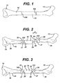
- FIG. 1 shows a femur 10 with proximal and distal ends 12, 14.
- the proximal end 12 of the femur 10 comprises the femoral head and adjacent bone tissue; the distal end 14 of the femur comprises the femoral condyles and adjacent bone tissue.
- FIG. 1 also illustrates in phantom the intercalary segment 16 of diaphyseal bone that has been removed, due to, for example, disease or severe trauma.
- the present invention is illustrated in use with the femur, it should be understood that the invention is not so limited; the invention could be used in any other long bone, such as the tibia or humerus, where a portion of the shaft has been removed or is missing.
- FIG. 2 illustrates the femur 10 of FIG. 1 in an intra-operative state, with a modular mid-shaft prosthetic trial system 18, prior to connection of the trial components.
- FIG. 3 illustrates the femur and trial system 18 of FIGS. 1-2 after the trial components have been connected.
- the mid-shaft prosthetic trial system 18 of FIGS. 2-3 is that disclosed in US-A 2003/0204262.
- the mid-shaft prosthetic trial system 18 illustrated in FIGS. 2-3 comprises a proximal stem trial 20, a distal stem trial 22 and a spacer trial 24.
- Each of the stem trials 20, 22 includes a head portion 26 from which extends a male connection post 28.
- the head portion 26 also includes a pair of notches 27 that receive tabs 29 on the spacer trial 24.
- Each of the stem trials 20, 22 also includes a stem portion 30 that is shaped to be received in the intramedullary canal of the bone.
- the two stem trials 20, 22 may be inserted in the intramedullary canals of the two spaced ends 12, 14 of the bone 10.
- the spacer trial 24 can be connected to one of the stem trials 20, 22 before the stem portion is inserted, or could also be connected after the stem portion is inserted.
- the native proximal and distal ends 12, 14 of the bone 10 with the proximal and distal stem trials 20, 22 and spacer trial 24 must be distracted, or moved in the proximal-distal direction, by at least a distance "d" (shown in FIG.
- the dimension "d" is typically on the order of 20 mm. This degree of proximal-distal distraction of the native bone ends 12, 14 could damage the surrounding soft tissue and soft tissue that is connected to the native bone ends 12, 14.
- the present invention obviates the need for proximal-distal distraction of the native bone ends 12, 14 during trialing while retaining the advantages of the system disclosed in US-A-2003/0204262.
- two stem trial components 20, 22 of the type disclosed in US-A-2003/0204262 (or permanent stem implant components of the type disclosed for example in US-A-2003/0204267) can be connected to an intervening three-part spacer without undue distraction of the native proximal and distal end bone portions 12, 14.
- the three-part spacer of the present invention comprises a first spacer segment 32, a second spacer segment 34 and a retaining ring 36.
- An intercalary orthopaedic system including the three-part spacer of the present invention could include stem components 20, 22 like those shown in FIGS. 4-6 with stems 38 of different lengths or other different characteristics.
- all of the stem components 20, 22 would have head portions 26 of the same size and shape to allow the stem components to be used interchangeably in the system described in US-A-2003/ 0204262.
- the posts 28 would be the same dimensions and shapes so that they can be received in all of the female parts of the system.
- the intercalary orthopaedic system would typically include surgical instruments for resecting and preparing the bone, intercalary implants and intercalary trials.
- the intercalary implants may have features such as those disclosed in US-A-2004/0193268, US-A-2004/0193267, and US-A-2003/0204267.
- tissue means a device that replicates one or more features of an implant component and that is intended to be temporarily placed in the patient's body to allow intraoperative assessment of the effects of using that implant component, and to be removed from the patient's body and replaced with an implant component during the same surgical procedure.
- the trial replicates one or more dimensional features of the implant component to allow for assessment of the size of the implant component.
- several trials are usually included in the system, corresponding with the sized of implants available in the system. Many orthopaedic trials come in contact with native bone, or a resected surface of native bone.
- references herein to the first spacer segment 32, second spacer segment 34, proximal stem component and distal stem component are intended to be generic terms including both trial spacer segments or stem components and implant spacer segments or stem components unless expressly limited to one or the other type of segment or component.
- first spacer segment includes both trial spacer segments and implant spacer segments unless expressly limited to one or the other type of spacer segment.
- first spacer segment 32 and second spacer segment 34 have open female ends 40 with chamfers leading to interior walls 41 defining interior bores 42.
- the interior wall 41 of each spacer segment 32, 34 also has a circular interior groove 44.
- the interior grooves 44 are spaced 8.26 mm (0.325 inch) from the open female end 40; each illustrated groove 44 comprises a full radius of 5.1 mm (0.200 inch).
- Each bore 42 can receive the post 28 of one of the stem components 20, 22.
- the interior bores 42 and interior grooves 44 of both trial segments 32, 34 are similar to those described in US-A-2003/0204262 so that each bore 42 can also receive and temporarily lock with a post 28 of one of male ends of one of the other trial system components described in US-A-2003/0204262.
- the depth of the bore 42 of the first trial segment 32 is calibrated to the length of the posts so that any trial component of the system having a post like that described in US-A-2003/0204262 can mate with the first trial segment 32.
- first and second spacer segments 32, 34 may vary from those illustrated if the first and second spacer segments are intended to complement a components of a trial system having shapes and retention mechanisms different from those illustrated for the proximal and distal stem trials 20, 22.
- the present invention is not limited to any particular interior structure for the first and second spacer segments and is not limited to the use of canted-coil springs unless expressly called for in the claims.
- some connection mechanism such as Morse tapers, would be used instead of the canted-coil spring and groove system illustrated.
- Both the first spacer segment 32 and the second spacer segment 34 have diametrically opposed tabs 29 like those described in US-A-2003/0204267 and US-A-2003/0204262. Each tab 29 can be received in one of the notches 27 of one of the stem components 20, 22. However, it should be understood that the invention is not limited to the use of such tabs and notches unless expressly called for in the claims. Other anti-rotation features can be used, or, it may not be necessary to include anti-rotation features in every case.
- both the first spacer segment 32 and the second spacer segment 34 also have pressure relief bores 48 at the end walls defining the interior bores 42 so that air pressure can be relieved as stem components 20,22 and spacer segments 32, 34 are brought together. It should be understood that the locations, shapes and sizes shown for the pressure relief bores 48 are provided for purposes of illustration only; the invention is not limited to the illustrated means of relieving pressure unless expressly called for in the claims.
- the first spacer segment 32 includes exterior wall sections defining an exterior female portion 50 opposite the opening into the opening 40 into the interior bore 42.
- the exterior wall sections of the illustrated first spacer segment 32 include: a pair of spaced co-planar inner shoulders 52, 54; a pair of spaced parallel intermediate inner walls 56, 58; a pair of co-planar end surfaces, 60, 62; a transverse wall 64 extending between the parallel intermediate inner walls 56, 58; a threaded outer surface 66; and a cylindrical surface 67 surrounding the groove 44 and a portion of the interior bore 42.
- the spaced inner shoulders 52, 54 of the first spacer segment 32 lie in a plane perpendicular to the central longitudinal axis 68 of the first spacer segment 32, and the spaced intermediate inner walls 56, 58 are spaced from and parallel to the central longitudinal axis 68 of the first spacer segment 32.
- the intermediate inner walls 56, 58 are adjacent to the inner shoulders 52, 54 and to the transverse wall 64; together, these walls 56, 58, 64 and shoulders 52, 54 define a T-shaped female transverse slot 69.
- the transverse slot 69 is open at both ends so that the transverse slot is capable of receiving a complementary male portion of the second spacer segment 34 when the first and second spacer segments 32, 34 are assembled as shown in FIGS. 4-6.
- FIGS. 11-13 A second spacer segment 34 with a male portion 70 complementary to the female portion 50 is illustrated in FIGS. 11-13.
- the illustrated male portion 70 comprises a transverse projection with a size and shape that complements the size and shape of the transverse slot 69, including the undercuts. As best seen in FIG.
- the illustrated transverse male portion or projection 70 includes: a transverse end wall 72 perpendicular to the central longitudinal axis 74 of the second trial segment 34; a pair of spaced walls 76, 78 perpendicular and adjacent to the transverse end wall 72; a pair of spaced co-planar shoulders 80, 82 spaced from an parallel to the transverse end wall 72; a pair of spaced parallel intermediate walls 84, 86 perpendicular and adjacent to the shoulders 80, 82; together, walls 76, 78, 84, 86 and shoulders 80, 82 define a T-shaped male projection 70.
- the transverse male portion or projection 70 and female transverse slot 69 are sized and shaped so that the first and second spacer segments 32, 34 can be connected together by sliding the transverse male portion or projection 70 into the female transverse slot 69 as shown in FIGS. 4-5.
- the two spacer segments 32, 34 can be connected without moving the spacer segments 32, 34 and bone portions 12, 14 in a proximal-distal direction (that is, without moving the spacer segments 32, 34 along their longitudinal axes 68, 74).
- the first and second spacer segments 32, 34 can be connected by moving one or both of the spacer segments 32, 34 in a direction other than the proximal-distal direction, such as in a generally medial-lateral direction as shown in FIG.
- a mid-shaft prosthetic trial or implant can be assembled intraoperatively after the stem components 20, 22 have been inserted or implanted without substantial distraction of the native bone portions 12, 14.
- the illustrated embodiment of the invention also includes the retaining ring 36 shown in FIGS. 4-6 and 14-21.
- the retaining ring 36 is annular, with an outer surface 90 that is knurled or textured in the illustrated embodiment to facilitate turning of the ring by hand during surgery.
- the interior surface 92 of the retaining ring 36 is threaded, as shown in FIGS. 16 and 21.
- the interior dimension of the retaining ring 36 and its thread pattern allow the retaining ring to be threaded onto the threaded outer surface 66 of the first spacer segment 32 and moved between an unlocked position and a locked position.
- FIGS. 4-5, 17 and 19 The unlocked position of the retaining ring 36 on the first spacer segment 32 is illustrated in FIGS. 4-5, 17 and 19. In this initial position, the entire transverse female slot 69 of the first spacer segment 32 is exposed, and the male portion 70 of the second spacer segment 34 can be slid into and out of the female slot 69 without interference from the retaining ring 36.
- FIGS. 6, 18 and 20-21 The locked position of the retaining ring 36 on the first spacer segment 32 is illustrated in FIGS. 6, 18 and 20-21.
- the entire transverse female slot 69 of the first spacer segment 32 is covered by the retaining ring, so that the male portion 70 of the second spacer segment 34 cannot be moved with respect to the slot 69.
- the male portion 70 is received in the slot 69 and the retaining ring 36 is in the locked position, the first and second spacer segments 32, 34 are retained together.
- the retaining ring 36 can be turned to return it to its unlocked position, wherein the male portion 70 of the second spacer segment 34 is again free to be slid into and out of the transverse slot 69 of the first spacer segment 32. All engagements and disengagements of the first and second spacer segments 32, 34 can be accomplished without moving the spacer segments 32, 34 in the proximal-distal direction, thus minimizing potential damage to native soft tissue at the native ends 12, 14 of the bone 10.
- an intercalary system or kit will desirably include first and second spacer segments 32, 34 that yield a variety of combined lengths.
- a surgical kit or trial system utilizing the teachings of the present invention could include the first spacer segment 32 of one length along with a plurality of second spacer segments 34 of various lengths to accommodate the need for different spans of bone loss and different lengths of bone.
- multiple lengths of either one or both of the spacer segments 50, 32 or 34 could be included in a surgical kit.
- the three-part spacer and other components can be made of any standard medical grade material for implants and trials.
- the spacer segments 32, 34, 36, retaining ring 36 and stem components 20, 22 for use as trials could all be made of a wrought cobalt chrome ccm+ alloy (co-cr-mo MS-100002-1083) or surgical grade stainless steel.
- these components 32, 34, 36 could be made of titanium or a co-cr-mo alloy, for example.
- the illustrated mating T-shaped male portion 70 and T-shaped female slot 69 represent one example of an interface that can be used in the present invention, and that other interfaces could be used.
- the male portion 70 and female portion 69 can comprise a mating dovetail 70A and dovetail slot 69A, or as shown in FIG. 25, a tongue 70B and groove 69B configuration could be used.
- the "male portion” and “female portion” could comprise any mating projection and opening.
- the mating projection and opening allow the two components to be joined through relative sliding movement (in the medial-lateral direction) rather than through longitudinal movement (in the proximal-distal direction).
- any structure that can selectively limit this relative movement between these two components to lock the components together can serve as a retaining device (such as retaining ring 36).
- the surgeon can prepare the long bone (e.g. the femur, tibia, humerus, etc.) to remove the diseased portion of the diaphyses or to remove bone fragments produced by some injury.
- the surgeon can then ream the intramedullary canals of the healthy proximal and distal bone portions 12, 14 in a standard manner to receive the stems of the stem trials 20, 22.
- the inner ends 100, 102 (see FIG. 1) of the native bone portions 12, 14 can be resected to provide a generally flat surface against which the stem trials 20, 22 can seat.
- the surgeon can use the stem components described in US-A-2003/ 0204262.
- the surgeon can assemble the illustrated stem component 20 with the illustrated first spacer segment 32 by inserting the male post 28 of the stem component 20 into the bore 42 of the first spacer segment 32 until the appropriate temporary lock is created between the two components 20, 32.
- the temporary lock can be accomplished through use of the illustrated canted-coil spring 46 in combination with the groove 44 in the first trial segment and groove in the male post 28 of the stem trial.
- the retaining ring 36 can be assembled with the first spacer segment 32 by threading it onto the threaded outer surface 66 of the first spacer segment until the retaining ring is in the unlocked position, creating a first trial sub-assembly, shown at 104 in FIG. 22.
- the surgeon can then assemble the other stem component 22 with the second spacer segment 34 by inserting the male post 28 of the stem component 22 into the bore 42 of the second spacer segment 34, creating a second trial sub-assembly shown at 106 in FIG. 23.
- the stem of each trial sub-assembly can then be temporarily inserted in the prepared intramedullary canal of the respective native bone portion 12, 14.
- the two sub-assemblies 104, 106 can be connected as shown in FIGS. 4-6 to create the intercalary trial assembly.
- the adjacent male portion 70 and female portion 50 of the sub-assemblies 104, 106 can be moved slightly in a generally medial-lateral direction (or anterior-posterior direction) and the male portion 70 can then be inserted into the female transverse slot 69. No proximal-distal distraction is necessary.
- the sub-assemblies 104, 106 can then be brought together until the male portion 70 is fully received in the female transverse slot 69.
- the surgeon can then turn the retaining ring 36 until the retaining ring 36 is moved to the locked position, thus retaining the two sub-assemblies together. If the surgeon is dissatisfied with the assembled trial (for example, if the length of the exposed portion does not result in an even limb length for the patient), the surgeon can quickly and easily disassemble the trial by turning the retaining ring 36 until it reaches the unlocked position and then sliding the male portion 70 out of the female transverse slot 69 (again, without requiring excessive movement in the proximal-distal direction). The surgeon can continue with different sizes of trial segments 32, 34 until satisfied that the final prosthetic implant will best suit the needs of the patient. Once satisfied, the surgeon can then separately remove each sub-assembly 104, 106 from the native bone ends 12, 14 and then can permanently implant an intercalary prosthesis corresponding with the trial assembly that yielded the most satisfactory results.
Abstract
Description
- The present invention relates to prosthetic systems for replacement of parts of bones, and more particularly to prosthetic systems having components that can be connected and disconnected in situ without damaging soft tissue through distraction of bone segments.
- Severe trauma and disease can lead to significant amounts of bone loss. In some instances, it is necessary to excise intercalary bone from a long bone, that is, part of the diaphysis or bone shaft between the ends of the long bone, but it is not necessary to excise the ends of the long bone. Thus, for example, a portion of the shaft of the femur may need to be excised to remove a malignancy, while the ends of the femur defining parts of the hip and knee joint may be healthy. Similarly, it may be necessary to excise part of the shaft of the tibia or humerus while the ends of these bones are healthy. Rather than remove the healthy ends of the bone, it may be desirable to leave the healthy portions of the bone in place and remove the damaged or diseased bone. In these circumstances, the empty span between the ends of the bone must be replaced with some type of mid-shaft prosthesis that spans the distance between the native bone ends. The mid-shaft prosthesis can include stems that fit into the intramedullary canals of the native bone ends and a body that extends between these stems. However, it may be difficult to implant such a mid-shaft prosthesis. Implantation can require that the native bone ends be distracted proximally and distally in order to fit the mid-shaft prosthesis into position. Since the native bone ends are surrounded by and connected to soft tissue, distraction of the native bone ends can damage the soft tissue and the connections between the soft tissue and the native bone ends.
- During surgical procedures to replace part of a bone with a prosthesis, orthopaedic trials are typically used. A surgeon uses an orthopaedic trial to ensure that the proper implant size will be used, to make the appropriate cuts and reams in the bone, and to ensure a proper alignment and component thickness prior to implanting the prosthetic components.
- For orthopaedic trials to be most useful, it is desirable that they replicate the sizes and shapes of the final implant components to be used. Therefore, it is desirable that orthopaedic trials offer the same flexibility as offered by the final implants. To optimize the utility of such orthopaedic trials, it is also desirable that these orthopaedic trials also be easily and quickly assembled or connected and disassembled or disconnected.
- For orthopaedic trials that are sized and shaped to mimic final intercalary implant components, the mid-shaft trials can include stems that fit into the intramedullary canals of the native bone ends and a trial body that extends between these stems. However, as described above with respect to intercalary implants, it may be difficult to insert such a mid-shaft trial without damaging the soft tissue at the native bone ends.
- The present invention addresses the need for orthopaedic components, such as trials and implants, that offer flexibility, that can be easily and quickly assembled or connected and disassembled or disconnected, and that can be temporarily inserted or implanted while minimizing damage to the soft tissue at the remaining portions of native bone.
- In one aspect, the invention provides orthopaedic system comprising a set of implant components sized and shaped to replace a portion of a bone, a set of trial components sized and shaped to replicate at least one feature of the implant components and a set of instruments for use in preparing the bone to receive the implant components, wherein at least one of the sets includes:
- a first member having a longitudinal axis;
- a second member having a longitudinal axis; and
- a retainer;
- one of the members having a male portion and the other of the members having surfaces defining a female portion;
- the female portion being capable of receiving the male portion to connect the first and second members together;
- wherein the female portion and the male portion are sized and shaped so that the male portion can be moved into the female portion through relative movement in a direction other than longitudinal; and
- wherein the retainer is movable between an unlocked position wherein relative movement between the male portion and female portion is possible and a locked position wherein relative movement between the male portion and female portion is restricted.
- In another aspect, the invention provides an intercalary orthopaedic system to span a space in the shaft of a long bone between native proximal and distal ends of the long bone, the system comprising:
- a first spacer segment to be secured to the native proximal end of the long bone, the first spacer segment having a longitudinal axis;
- a second spacer segment to be secured to the native distal end of the long bone, the second spacer segment having a longitudinal axis; and
- a retaining ring;
- one of the spacer segments having a male portion and the other of the spacer segments having surfaces defining a female portion;
- the female portion being capable of receiving the male portion to connect the first and second spacer segments together to span the space in the shaft of the long bone;
- the female portion having a threaded exterior surface;
- wherein the female portion and the male portion are sized and shaped so that the male portion can be moved into the female portion through relative movement in a direction other than longitudinal; and
- wherein the retaining ring has a threaded interior surface sized and shaped to be capable of being threaded onto the threaded exterior surface of the female portion to retain the first and second spacer segment together when the male portion is received in the female portion.
- In a further aspect, the invention provides an intercalary orthopaedic system spanning a space in the shaft of a long bone between native proximal and distal ends of the long bone comprising:
- a first spacer segment secured to the native proximal end of the long bone;
- a second spacer segment secured to the native distal end of the long bone; and
- a retaining ring;
- one of the spacer segments having a male portion and the other of the spacer segments having surfaces defining a female portion;
- the female portion receiving the male portion to connect the first and second spacer segments together to span the space in the shaft of the long bone;
- the female portion having a threaded exterior surface;
- wherein the retaining ring has a threaded interior surface threaded onto the threaded exterior surface of the female portion to retain the first and second segment together.
- Accordingly, the invention provides an orthopaedic system comprising a set of implant components sized and shaped to replace a portion of a bone, a set of trial components sized and shaped to replicate or duplicate at least one feature of the implant components and a set of instruments for use in preparing the bone to receive the implant components. At least one of the sets includes a first member having a longitudinal axis, a second member having a longitudinal axis, and a retainer. One of the members has a male portion and the other of the members has wall sections defining a female portion. The female portion is capable of receiving the male portion to connect the first and second members together. The female portion and the male portion are sized and shaped so that the male portion can be moved into the female portion through relative movement in a direction other than longitudinal. The retainer is movable between an unlocked position wherein relative movement between the male portion and female portion is possible and a locked position wherein relative movement between the male portion and female portion is restricted.
- The invention also provides an intercalary orthopaedic system to span a space in the shaft of a long bone between native proximal and distal ends of the long bone. The system comprises a first spacer segment, a second spacer segment and a retaining ring. The first spacer segment is to be secured to the native proximal end of the long bone and has a longitudinal axis. The second spacer segment is to be secured to the native distal end of the long bone and has a longitudinal axis. One of the spacer segments has a male portion and the other of the spacer segments has surfaces defining a female portion. The female portion is capable of receiving the male portion to connect the first and second spacer segments together to span the space in the shaft of the long bone. The male and female portions may comprise a T-shaped projection and a mating T-slot, mating dovetails, or tongues and grooves, for example. The female portion has a threaded exterior surface. The female portion and the male portion are sized and shaped so that the male portion can be moved into the female portion through relative movement in a direction other than longitudinal. The retaining ring has a threaded interior surface sized and shaped to be capable of being threaded onto the threaded exterior surface of the female portion to retain the first and second spacer segments together when the male portion is received in the female portion.
- The invention further provides an intercalary orthopaedic system spanning a space in the shaft of a long bone between native proximal and distal ends of the long bone comprising a first spacer segment, a segment spacer segment and a retaining ring. The first spacer segment is secured to the native proximal end of the long bone. The second spacer segment is secured to the native distal end of the long bone. One of the spacer segments has a male portion and the other of the spacer segments has surfaces defining a female portion. The female portion receives the male portion to connect the first and second spacer segments together to span the space in the shaft of the long bone. The female portion has a threaded exterior surface. The retaining ring has a threaded interior surface threaded onto the threaded exterior surface of the female portion to retain the first and second spacer segments together.
- Embodiments of the invention are now described by way of example with reference to the accompanying drawings, in which:
- FIG. 1 is a top plan or anterior view of a femur, showing the native proximal and distal ends of the femur and showing an excised intercalary segment of the diaphysis of the femur in phantom between the native ends of the femur;
- FIG. 2 is a top plan or anterior view of the femur of FIG. 1, shown with one type of intercalary prosthesis trial prior to connection of all the parts of the intercalary prosthetic trial;
- FIG. 3 is a top plan or anterior view of the femur of FIGS. 1-2, shown with all parts of the intercalary prosthesis trial connected together;
- FIG. 4 is a top plan or anterior view of the femur of FIG. 1, shown with an embodiment of the intercalary prosthetic system of the present invention prior to connection of all the parts of the intercalary prosthetic system;
- FIG. 5 is a top plan or anterior view of the femur of FIGS. 1 and 4, shown with parts of the intercalary prosthetic system of FIG. 4 connected together and prior to turning the retaining ring;
- FIG. 6 is a top plan or anterior view of the femur of FIGS. 1 and 4-5, shown with parts of the intercalary prosthetic system connected together as in FIG. 5, and after turning the retaining ring to lock the first and second spacer segments together;
- FIG. 7 is a perspective view of one embodiment of a first spacer segment for use with the intercalary prosthetic system of the present invention;
- FIG. 8 is a top plan view of the spacer segment of FIG. 7;
- FIG. 9 is a side view or elevation of the spacer segment of FIGS. 7-8;
- FIG. 10 is a cross-section of the spacer segment of FIGS. 7-9, taken along line 10-10 of FIG. 9;
- FIG. 11 is a side view or elevation of an embodiment of a second spacer segment for use with the intercalary prosthetic system of the present invention;
- FIG. 12 is a top plan view of the spacer segment of FIG. 11;
- FIG. 13 is a cross-section of the spacer segment of FIGS. 11-12, taken along line 13-13 of FIG. 11;
- FIG. 14 is a side view or elevation of an embodiment of a retaining ring for use with intercalary prosthetic system of the present invention;
- FIG. 15 is a top plan view of the retaining ring of FIG. 14;
- FIG. 16 is a cross-section of the retaining ring of FIGS. 14-15, taken along line 16-16 of FIG. 14;
- FIG. 17 is a cross-section of the first and second spacer segments assembled with stem components with the retaining ring in the unlocked position, the cross-section being taken along a coronal plane through the assembly illustrated in FIG. 5;
- FIG. 18 is a cross-section of the first and second spacer segments assembled with stem components with the retaining ring in the locked position, the cross-section being taken along a coronal plane through the assembly illustrated in FIG. 6;
- FIG. 19 is a cross-section of the first and second spacer segments assembled with stem components with the retaining ring in the unlocked position, the cross-section being taken along a sagittal plane through line 19-19 of FIG. 5;
- FIG. 20 is a cross-section of the first and second spacer segments assembled with stem components with the retaining ring in the locked position, the cross-section being taken along a sagittal plane through line 20-20 of FIG. 6;
- FIG. 21 is an enlarged cross-section of the connection between the first and second spacer segments with the retaining ring in the locked position;
- FIG. 22 is an elevation or side view of a first sub-assembly of a first spacer segment, first stem component and retaining ring;
- FIG. 23 is an elevation or side view of a second sub-assembly of a second spacer segment and a second stem component;
- FIG. 24 is an enlarged cross-section of the connection between another embodiment of first and second spacer segments with the retaining ring in the locked position, the male portion and female portion comprising mating dovetail and dovetail slot; and
- FIG. 25 is an enlarged cross-section of the connection between another embodiment of first and second spacer segments with the retaining ring in the locked position, the male portion and female portion comprising mating tongues and grooves.
- Referring to the drawings, FIG. 1 shows a
femur 10 with proximal and distal ends 12, 14. Theproximal end 12 of thefemur 10 comprises the femoral head and adjacent bone tissue; thedistal end 14 of the femur comprises the femoral condyles and adjacent bone tissue. FIG. 1 also illustrates in phantom theintercalary segment 16 of diaphyseal bone that has been removed, due to, for example, disease or severe trauma. Although the present invention is illustrated in use with the femur, it should be understood that the invention is not so limited; the invention could be used in any other long bone, such as the tibia or humerus, where a portion of the shaft has been removed or is missing. - FIG. 2 illustrates the
femur 10 of FIG. 1 in an intra-operative state, with a modular mid-shaftprosthetic trial system 18, prior to connection of the trial components. FIG. 3 illustrates the femur andtrial system 18 of FIGS. 1-2 after the trial components have been connected. The mid-shaftprosthetic trial system 18 of FIGS. 2-3 is that disclosed in US-A 2003/0204262. - The mid-shaft
prosthetic trial system 18 illustrated in FIGS. 2-3 comprises aproximal stem trial 20, adistal stem trial 22 and aspacer trial 24. Each of thestem trials head portion 26 from which extends amale connection post 28. Thehead portion 26 also includes a pair ofnotches 27 that receivetabs 29 on thespacer trial 24. Each of thestem trials - As shown in FIG. 2, to temporarily insert the mid-shaft
prosthetic trial system 18 in thebone 10, the twostem trials bone 10. Thespacer trial 24 can be connected to one of thestem trials bone 10 with the proximal anddistal stem trials spacer trial 24 must be distracted, or moved in the proximal-distal direction, by at least a distance "d" (shown in FIG. 2), corresponding with the length of thepost 28 so that thepost 28 can be inserted into the mating female portion of thespacer trial 24. In the illustrated embodiment, the dimension "d" is typically on the order of 20 mm. This degree of proximal-distal distraction of the native bone ends 12, 14 could damage the surrounding soft tissue and soft tissue that is connected to the native bone ends 12, 14. - To avert the potential for soft tissue damage, the present invention obviates the need for proximal-distal distraction of the native bone ends 12, 14 during trialing while retaining the advantages of the system disclosed in US-A-2003/0204262. As shown in FIGS. 4-6 and 17-20, two
stem trial components end bone portions first spacer segment 32, asecond spacer segment 34 and a retainingring 36. - An intercalary orthopaedic system including the three-part spacer of the present invention could include stem
components stem components head portions 26 of the same size and shape to allow the stem components to be used interchangeably in the system described in US-A-2003/ 0204262. Thus, theposts 28 would be the same dimensions and shapes so that they can be received in all of the female parts of the system. - The intercalary orthopaedic system would typically include surgical instruments for resecting and preparing the bone, intercalary implants and intercalary trials. The intercalary implants may have features such as those disclosed in US-A-2004/0193268, US-A-2004/0193267, and US-A-2003/0204267.
- As used herein, "trial" means a device that replicates one or more features of an implant component and that is intended to be temporarily placed in the patient's body to allow intraoperative assessment of the effects of using that implant component, and to be removed from the patient's body and replaced with an implant component during the same surgical procedure. Typically the trial replicates one or more dimensional features of the implant component to allow for assessment of the size of the implant component. In the case of orthopaedic systems, several trials are usually included in the system, corresponding with the sized of implants available in the system. Many orthopaedic trials come in contact with native bone, or a resected surface of native bone.
- It should also be understood that references herein to the
first spacer segment 32,second spacer segment 34, proximal stem component and distal stem component are intended to be generic terms including both trial spacer segments or stem components and implant spacer segments or stem components unless expressly limited to one or the other type of segment or component. For example, the expression "first spacer segment" includes both trial spacer segments and implant spacer segments unless expressly limited to one or the other type of spacer segment. Thus, although the system illustrated in FIGS. 4-25 has features that may be particularly applicable to orthopaedic trials, it should be understood that the principles of the present invention are applicable to implants as well. Moreover, the principles of the present invention could be applied to surgical instruments, and could also be applied to other medical and non-medical uses. - Referring now to FIGS. 10 and 13, the illustrated
first spacer segment 32 andsecond spacer segment 34 have open female ends 40 with chamfers leading tointerior walls 41 defining interior bores 42. Theinterior wall 41 of eachspacer segment interior groove 44. In the illustrated embodiments, theinterior grooves 44 are spaced 8.26 mm (0.325 inch) from the openfemale end 40; each illustratedgroove 44 comprises a full radius of 5.1 mm (0.200 inch). - Each bore 42 can receive the
post 28 of one of thestem components interior grooves 44 of bothtrial segments post 28 of one of male ends of one of the other trial system components described in US-A-2003/0204262. The depth of thebore 42 of thefirst trial segment 32 is calibrated to the length of the posts so that any trial component of the system having a post like that described in US-A-2003/0204262 can mate with thefirst trial segment 32. A garter-type canted-coil spring of the type illustrated in FIGS. 15-16 of US-A-2003/ 0204262, available from Bal Seal Engineering Co., Inc. of Foothill Ranch, California (Part No. X205498), may be included within theinterior groove 44 each of the illustratedtrial segments male posts 28 within thetrial segments - It should be understood that the interiors of the first and
second spacer segments distal stem trials - Both the
first spacer segment 32 and thesecond spacer segment 34 have diametrically opposedtabs 29 like those described in US-A-2003/0204267 and US-A-2003/0204262. Eachtab 29 can be received in one of thenotches 27 of one of thestem components - As shown in FIGS. 7-8, 10, 12-13 and 17-20, both the
first spacer segment 32 and thesecond spacer segment 34 also have pressure relief bores 48 at the end walls defining the interior bores 42 so that air pressure can be relieved asstem components spacer segments - Referring to FIGS. 7-10, the
first spacer segment 32 includes exterior wall sections defining an exteriorfemale portion 50 opposite the opening into theopening 40 into the interior bore 42. As best seen in FIG. 21, the exterior wall sections of the illustratedfirst spacer segment 32 include: a pair of spaced co-planarinner shoulders inner walls transverse wall 64 extending between the parallel intermediateinner walls outer surface 66; and acylindrical surface 67 surrounding thegroove 44 and a portion of the interior bore 42. - As can be seen in FIG. 21, the spaced
inner shoulders first spacer segment 32 lie in a plane perpendicular to the centrallongitudinal axis 68 of thefirst spacer segment 32, and the spaced intermediateinner walls longitudinal axis 68 of thefirst spacer segment 32. The intermediateinner walls inner shoulders transverse wall 64; together, thesewalls shoulders transverse slot 69. Thetransverse slot 69 is open at both ends so that the transverse slot is capable of receiving a complementary male portion of thesecond spacer segment 34 when the first andsecond spacer segments - A
second spacer segment 34 with amale portion 70 complementary to thefemale portion 50 is illustrated in FIGS. 11-13. The illustratedmale portion 70 comprises a transverse projection with a size and shape that complements the size and shape of thetransverse slot 69, including the undercuts. As best seen in FIG. 21, the illustrated transverse male portion orprojection 70 includes: atransverse end wall 72 perpendicular to the centrallongitudinal axis 74 of thesecond trial segment 34; a pair of spacedwalls transverse end wall 72; a pair of spacedco-planar shoulders transverse end wall 72; a pair of spaced parallelintermediate walls shoulders walls shoulders male projection 70. - The transverse male portion or
projection 70 and femaletransverse slot 69 are sized and shaped so that the first andsecond spacer segments projection 70 into the femaletransverse slot 69 as shown in FIGS. 4-5. As there shown, the twospacer segments spacer segments bone portions spacer segments longitudinal axes 68, 74). Instead, the first andsecond spacer segments spacer segments intercalary spacer segments stem components native bone portions - When the male and
female portions spacer segments projection 70 do not extend outward beyond the threads of the threadedouter surface 66 of thefirst spacer segment 32. To secure the first and secondintercalary spacer segments ring 36 shown in FIGS. 4-6 and 14-21. - As shown in FIGS. 14-16, the retaining
ring 36 is annular, with anouter surface 90 that is knurled or textured in the illustrated embodiment to facilitate turning of the ring by hand during surgery. Theinterior surface 92 of the retainingring 36 is threaded, as shown in FIGS. 16 and 21. The interior dimension of the retainingring 36 and its thread pattern allow the retaining ring to be threaded onto the threadedouter surface 66 of thefirst spacer segment 32 and moved between an unlocked position and a locked position. - The unlocked position of the retaining
ring 36 on thefirst spacer segment 32 is illustrated in FIGS. 4-5, 17 and 19. In this initial position, the entire transversefemale slot 69 of thefirst spacer segment 32 is exposed, and themale portion 70 of thesecond spacer segment 34 can be slid into and out of thefemale slot 69 without interference from the retainingring 36. - The locked position of the retaining
ring 36 on thefirst spacer segment 32 is illustrated in FIGS. 6, 18 and 20-21. In this locked position, the entire transversefemale slot 69 of thefirst spacer segment 32 is covered by the retaining ring, so that themale portion 70 of thesecond spacer segment 34 cannot be moved with respect to theslot 69. Thus, when themale portion 70 is received in theslot 69 and the retainingring 36 is in the locked position, the first andsecond spacer segments second spacer segments ring 36 can be turned to return it to its unlocked position, wherein themale portion 70 of thesecond spacer segment 34 is again free to be slid into and out of thetransverse slot 69 of thefirst spacer segment 32. All engagements and disengagements of the first andsecond spacer segments spacer segments bone 10. - It should be understood that the lengths of
intercalary bone segments 16 needing replacement will vary substantially, depending on many factors, such as the extent of disease or injury or the age or size of the patient. Accordingly, an intercalary system or kit will desirably include first andsecond spacer segments first spacer segment 32 of one length along with a plurality ofsecond spacer segments 34 of various lengths to accommodate the need for different spans of bone loss and different lengths of bone. Alternatively, multiple lengths of either one or both of thespacer segments - The three-part spacer and other components can be made of any standard medical grade material for implants and trials. For example, the
spacer segments ring 36 andstem components components - It should also be understood that the illustrated mating T-shaped
male portion 70 and T-shapedfemale slot 69 represent one example of an interface that can be used in the present invention, and that other interfaces could be used. For example, as shown in FIG. 24, themale portion 70 andfemale portion 69 can comprise amating dovetail 70A anddovetail slot 69A, or as shown in FIG. 25, atongue 70B and groove 69B configuration could be used. Accordingly, unless expressly limited by the claims to a particular configuration, the "male portion" and "female portion" could comprise any mating projection and opening. Preferably, the mating projection and opening allow the two components to be joined through relative sliding movement (in the medial-lateral direction) rather than through longitudinal movement (in the proximal-distal direction). Similarly, any structure that can selectively limit this relative movement between these two components to lock the components together can serve as a retaining device (such as retaining ring 36). - To use the illustrated
intercalary spacer segments distal bone portions stem trials native bone portions stem trials - The surgeon can assemble the illustrated
stem component 20 with the illustratedfirst spacer segment 32 by inserting themale post 28 of thestem component 20 into thebore 42 of thefirst spacer segment 32 until the appropriate temporary lock is created between the twocomponents coil spring 46 in combination with thegroove 44 in the first trial segment and groove in themale post 28 of the stem trial. The retainingring 36 can be assembled with thefirst spacer segment 32 by threading it onto the threadedouter surface 66 of the first spacer segment until the retaining ring is in the unlocked position, creating a first trial sub-assembly, shown at 104 in FIG. 22. The surgeon can then assemble theother stem component 22 with thesecond spacer segment 34 by inserting themale post 28 of thestem component 22 into thebore 42 of thesecond spacer segment 34, creating a second trial sub-assembly shown at 106 in FIG. 23. The stem of each trial sub-assembly can then be temporarily inserted in the prepared intramedullary canal of the respectivenative bone portion - Once both
sub-assemblies sub-assemblies male portion 70 andfemale portion 50 of thesub-assemblies male portion 70 can then be inserted into the femaletransverse slot 69. No proximal-distal distraction is necessary. Thesub-assemblies male portion 70 is fully received in the femaletransverse slot 69. The surgeon can then turn the retainingring 36 until the retainingring 36 is moved to the locked position, thus retaining the two sub-assemblies together. If the surgeon is dissatisfied with the assembled trial (for example, if the length of the exposed portion does not result in an even limb length for the patient), the surgeon can quickly and easily disassemble the trial by turning the retainingring 36 until it reaches the unlocked position and then sliding themale portion 70 out of the female transverse slot 69 (again, without requiring excessive movement in the proximal-distal direction). The surgeon can continue with different sizes oftrial segments - It should be understood that the above-described surgical technique is provided by way of example only, and that the present invention is not limited to that technique unless expressly called for in the claims. Variations are possible; for example, the surgeon could opt to connect the
trial segments stem trials native bone portions - As can be appreciated from the above description, the principles of the invention can also be used outside of the orthopaedic and medical fields. In any field where it is desirable to join two components through transverse rather than longitudinal movement, mating male projections and female slots and retainers similar to those illustrated could be used.
Claims (13)
- An orthopaedic system comprising a set of implant components sized and shaped to replace a portion of a bone, a set of trial components sized and shaped to replicate at least one feature of the implant components and a set of instruments for use in preparing the bone to receive the implant components, wherein at least one of the sets includes:a first member having a longitudinal axis;a second member having a longitudinal axis; anda retainer;one of the members having a male portion and the other of the members having surfaces defining a female portion;the female portion being capable of receiving the male portion to connect the first and second members together;wherein the female portion and the male portion are sized and shaped so that the male portion can be moved into the female portion through relative movement in a direction other than longitudinal; andwherein the retainer is movable between an unlocked position wherein relative movement between the male portion and female portion is possible and a locked position wherein relative movement between the male portion and female portion is restricted.
- The system of claim 1 wherein the first member comprises a first spacer segment and the second member comprises a second spacer segment.
- The system of claim 2 wherein the portion of bone to be replaced comprises an intercalary bone portion between two native ends of the bone and wherein the first member further includes a proximal stem component connected to the first spacer segment and the second member further includes a distal stem component connected to the second spacer segment, the proximal stem component including a stem sized and shaped to be received in the intramedullary canal of one native end of the bone and the distal stem component having a stem sized and shaped to be received in the intramedullary canal of the other native end of the bone.
- The system of claim 1 wherein the female portion is shaped to define a transverse slot.
- The system of claim 4 wherein the male portion comprises a transverse projection having a size and shape that complements the size and shape of the transverse slot of the female portion.
- The system of claim 5 wherein the transverse projection comprises a pair of spaced parallel shoulders and a pair of spaced parallel intermediate walls adjacent to the spaced parallel shoulders, the spaced parallel intermediate walls defining undercuts.
- The system of claim 6 wherein:the surfaces defining the female transverse slot include a pair of spaced parallel interior shoulders and a pair of spaced parallel intermediate interior walls adjacent to the spaced parallel interior shoulders, the spaced parallel intermediate interior walls defining undercuts;the spaced parallel shoulders of the projection of the male portion are sized and shaped to be received between the spaced parallel intermediate interior walls of the female portion; andthe spaced parallel shoulders of the female portion are sized and shaped to be received adjacent to the spaced parallel intermediate walls of the male portion.
- The system of claim 7 wherein the female portion has a threaded exterior surface at the level of the spaced parallel intermediate interior walls of the female portion
- The system of claim 5 wherein the transverse slot is T-shaped in cross-section and the male portion is T-shaped in cross-section.
- The system of claim 5 wherein the transverse slot is dovetailed in shape and the male portion is dovetailed in shape.
- The system of claim 5 wherein the transverse slot includes a groove and the male portion includes a rib.
- The system of claim 1 wherein the first member and second member comprise intercalary trials.
- The system of claim 1 wherein the retainer comprises a retaining ring.
Applications Claiming Priority (1)
| Application Number | Priority Date | Filing Date | Title |
|---|---|---|---|
| US10/952,581 US7198642B2 (en) | 2003-03-31 | 2004-09-24 | Orthopaedic spacer |
Publications (2)
| Publication Number | Publication Date |
|---|---|
| EP1639963A1 true EP1639963A1 (en) | 2006-03-29 |
| EP1639963B1 EP1639963B1 (en) | 2007-11-07 |
Family
ID=35335585
Family Applications (1)
| Application Number | Title | Priority Date | Filing Date |
|---|---|---|---|
| EP05255808A Not-in-force EP1639963B1 (en) | 2004-09-24 | 2005-09-21 | Orthopaedic spacer |
Country Status (4)
| Country | Link |
|---|---|
| US (1) | US7198642B2 (en) |
| EP (1) | EP1639963B1 (en) |
| AT (1) | ATE377400T1 (en) |
| DE (1) | DE602005003183T2 (en) |
Cited By (2)
| Publication number | Priority date | Publication date | Assignee | Title |
|---|---|---|---|---|
| EP2316388A1 (en) * | 2009-10-30 | 2011-05-04 | DePuy Products, Inc. | Modular trial mechanism |
| US11357630B2 (en) | 2017-03-31 | 2022-06-14 | Waldemar Link Gmbh & Co. Kg | Connecting sleeve for anchoring shafts of two oppositely arranged prostheses |
Families Citing this family (27)
| Publication number | Priority date | Publication date | Assignee | Title |
|---|---|---|---|---|
| US7497874B1 (en) * | 2001-02-23 | 2009-03-03 | Biomet Manufacturing Corp. | Knee joint prosthesis |
| EP1824419B1 (en) | 2004-12-17 | 2016-04-20 | DePuy Products, Inc. | Modular implant system |
| US7507256B2 (en) * | 2004-12-17 | 2009-03-24 | Depuy Products, Inc. | Modular implant system and method with diaphyseal implant |
| US7867282B2 (en) * | 2004-12-17 | 2011-01-11 | Depuy Products, Inc. | Modular implant system and method with diaphyseal implant and adapter |
| US8562616B2 (en) | 2007-10-10 | 2013-10-22 | Biomet Manufacturing, Llc | Knee joint prosthesis system and method for implantation |
| US8163028B2 (en) | 2007-01-10 | 2012-04-24 | Biomet Manufacturing Corp. | Knee joint prosthesis system and method for implantation |
| US8157869B2 (en) | 2007-01-10 | 2012-04-17 | Biomet Manufacturing Corp. | Knee joint prosthesis system and method for implantation |
| US8187280B2 (en) | 2007-10-10 | 2012-05-29 | Biomet Manufacturing Corp. | Knee joint prosthesis system and method for implantation |
| US8328873B2 (en) | 2007-01-10 | 2012-12-11 | Biomet Manufacturing Corp. | Knee joint prosthesis system and method for implantation |
| US8152807B2 (en) * | 2008-03-31 | 2012-04-10 | Olecranail Llc | Intramedullary device assembly and associated method |
| WO2010059860A1 (en) * | 2008-11-19 | 2010-05-27 | Endoorthopaedics, Inc. | Intramedullary repair system for bone fractures |
| US8454706B2 (en) | 2009-02-25 | 2013-06-04 | Brian C. de Beaubien | Antibiotic delivery system and method for treating an infected synovial joint during re-implantation of an orthopedic prosthesis |
| CA2708877C (en) * | 2009-07-07 | 2017-10-10 | National Oilwell Varco, L.P. | Retention means for a seal boot used in a universal joint in a downhole motor driveshaft assembly |
| WO2011044586A1 (en) * | 2009-10-10 | 2011-04-14 | Simplicity Orthopedics, Inc. | Method and apparatus for restoring a joint, including the provision and use of a longitudinally-adjustable and rotationally-adjustable joint prosthesis |
| US20110112649A1 (en) * | 2009-11-09 | 2011-05-12 | Biomet Manufacturing Corp. | Radial and ulnar replacement |
| EP2618757A1 (en) * | 2010-09-20 | 2013-07-31 | Synthes GmbH | Intramedullary nail |
| US8747479B2 (en) | 2011-04-26 | 2014-06-10 | Michael A. McShane | Tibial component |
| US9452056B2 (en) * | 2014-09-29 | 2016-09-27 | Biomet C.V. | Implants for fixation of the distal tibia |
| US9597203B2 (en) * | 2015-03-25 | 2017-03-21 | Tornier, Inc. | Modular humeral implant |
| US10433965B2 (en) | 2015-06-17 | 2019-10-08 | Joint Purification Systems Llc | Total joint replacement infection control devices and methods |
| CA3054194C (en) | 2017-02-21 | 2020-12-08 | Biomet Manufacturing, Llc | Implants for bridging osseous defects |
| CN106821551B (en) * | 2017-04-06 | 2018-05-22 | 四川大学华西医院 | Bushing type osteotomy section backbone prosthese |
| US10813769B2 (en) * | 2018-07-24 | 2020-10-27 | DePuy Synthes Products, Inc. | Baseplate of a modular shoulder joint prosthesis and related methods for implanting the same |
| CN108992156B (en) * | 2018-09-07 | 2024-03-15 | 北京爱康宜诚医疗器材有限公司 | Bone connector |
| EP3771442A1 (en) * | 2019-07-31 | 2021-02-03 | Ostium Group | Modular tool |
| US20210378827A1 (en) * | 2020-06-03 | 2021-12-09 | Howmedica Osteonics Corp. | Intercalary Endoprosthesis |
| US20230310167A1 (en) * | 2022-03-31 | 2023-10-05 | Howmedica Osteonics Corp. | Advanced Trial Spacers, Height Measuring Tool, and Inserter and Extractor Handle |
Citations (5)
| Publication number | Priority date | Publication date | Assignee | Title |
|---|---|---|---|---|
| EP0359485A1 (en) * | 1988-09-14 | 1990-03-21 | Pfizer Hospital Products Group, Inc. | Modular prosthesis |
| US20030204267A1 (en) | 2002-04-30 | 2003-10-30 | Hazebrouck Stephen A. | Modular limb preservation system |
| US20030204262A1 (en) | 2002-04-30 | 2003-10-30 | Ferguson Joe William | Quick disconnect orthopaedic trials |
| US20040193267A1 (en) | 2003-03-31 | 2004-09-30 | Jones Michael C. | Intercalary implant |
| US20040193268A1 (en) | 2003-03-31 | 2004-09-30 | Hazebrouck Stephen A. | Intercalary prosthesis, kit and method |
Family Cites Families (56)
| Publication number | Priority date | Publication date | Assignee | Title |
|---|---|---|---|---|
| US193268A (en) * | 1877-07-17 | Improvement in seed-planters | ||
| US193267A (en) * | 1877-07-17 | Improvement in grain-driers | ||
| US107883A (en) * | 1870-10-04 | Wells crumb | ||
| US2779966A (en) * | 1953-04-20 | 1957-02-05 | Robert E Torchia | Adjustable hinge |
| US3801213A (en) * | 1972-05-25 | 1974-04-02 | Kennametal Inc | Adjustable dovetail boring bar |
| US4011602A (en) * | 1975-10-06 | 1977-03-15 | Battelle Memorial Institute | Porous expandable device for attachment to bone tissue |
| US4016874A (en) * | 1976-05-19 | 1977-04-12 | Maffei Ernest J | Three-part intramedullary bone-setting pin |
| GB2094629B (en) * | 1981-03-14 | 1984-08-01 | Tsnii | Artifical hip knee and femur |
| US4467794A (en) * | 1982-02-08 | 1984-08-28 | Ernest Maffei | Intramedulary bone-setting assembly |
| US4502160A (en) * | 1983-10-27 | 1985-03-05 | Dow Corning Wright | Adjustable length prosthetic joint implant |
| DE3340767A1 (en) * | 1983-11-08 | 1985-05-15 | Mecron Medizinische Produkte Gmbh, 1000 Berlin | KIT FOR A RESECTION PROSTHESIS |
| US4634444A (en) * | 1984-02-09 | 1987-01-06 | Joint Medical Products Corporation | Semi-constrained artificial joint |
| US4655462A (en) * | 1985-01-07 | 1987-04-07 | Peter J. Balsells | Canted coiled spring and seal |
| DE3528728A1 (en) | 1985-08-09 | 1987-02-12 | Link Waldemar Gmbh Co | ENDOPROTHESIS TO REPLACE THE MEDIUM SECTION OF A LONG-STRETCHED BONE |
| DE3535158A1 (en) | 1985-10-02 | 1987-04-09 | Gmt Medizinische Technik Gmbh | SADDLE PROSTHESIS |
| US5314479A (en) * | 1986-08-15 | 1994-05-24 | Depuy Inc. | Modular prosthesis |
| US4787907A (en) * | 1987-02-03 | 1988-11-29 | Techmedica, Inc. | Morse taper |
| US4938768A (en) * | 1987-03-09 | 1990-07-03 | Henry Ford Hospital | Bone gap bridging and fusing device |
| US5011496A (en) * | 1988-02-02 | 1991-04-30 | Joint Medical Products Corporation | Prosthetic joint |
| US4888021A (en) * | 1988-02-02 | 1989-12-19 | Joint Medical Products Corporation | Knee and patellar prosthesis |
| US4915366A (en) * | 1988-04-25 | 1990-04-10 | Peter J. Balsells | Outside back angle canted coil spring |
| US4830344A (en) * | 1988-04-25 | 1989-05-16 | Peter J. Balsells | Canted-coil spring with turn angle and seal |
| US4826144A (en) * | 1988-04-25 | 1989-05-02 | Peter J. Balsells | Inside back angle canted coil spring |
| US4934666A (en) * | 1988-04-25 | 1990-06-19 | Peter J. Balsells | Coiled spring electromagnetic shielding gasket |
| US5108078A (en) * | 1988-04-25 | 1992-04-28 | Peter J. Balsells | Canted-coil spring loaded while in a cavity |
| US5079388A (en) * | 1989-12-01 | 1992-01-07 | Peter J. Balsells | Gasket for sealing electromagnetic waves |
| US5117066A (en) * | 1988-04-25 | 1992-05-26 | Peter J. Balsells | Retaining and locking electromagnetic gasket |
| US5072070A (en) * | 1989-12-01 | 1991-12-10 | Peter J. Balsells | Device for sealing electromagnetic waves |
| US4876781A (en) * | 1988-04-25 | 1989-10-31 | Peter J. Balsells | Method of making a garter-type axially resilient coiled spring |
| US5139276A (en) * | 1988-04-25 | 1992-08-18 | Peter J. Balsells | Canted coil spring radially loaded while in a cavity |
| FR2633509A1 (en) | 1988-07-04 | 1990-01-05 | Louyot Comptoir Lyon Alemand | Femoral component for hip prostheses |
| DE3903438C2 (en) | 1989-02-06 | 1998-07-09 | Gmt Medizinische Technik Gmbh | Modular hip joint endoprosthesis |
| US5100407A (en) * | 1990-09-04 | 1992-03-31 | Pfizer Hospital Products Group, Inc. | Modular trial hip replacement system |
| US5082390A (en) * | 1991-01-22 | 1992-01-21 | Peter J. Balsells | Latching, holding and locking spring apparatus |
| US5334184A (en) * | 1992-06-30 | 1994-08-02 | Bimman Lev A | Apparatus for intramedullary fixation broken bones |
| US5352227A (en) * | 1993-02-03 | 1994-10-04 | Howmedica Inc. | Intercalary device |
| US5358524A (en) * | 1993-02-16 | 1994-10-25 | Wright Medical Technology, Inc. | Adjustable length prosthetic implant |
| US5411348A (en) * | 1993-10-26 | 1995-05-02 | Bal Seal Engineering Company, Inc. | Spring mechanism to connect, lock and unlock, members |
| US6197065B1 (en) * | 1993-11-01 | 2001-03-06 | Biomet, Inc. | Method and apparatus for segmental bone replacement |
| AU2351395A (en) * | 1994-06-30 | 1996-01-25 | Howmedica Inc. | Modular femoral trial hip replacement system |
| US6364909B1 (en) * | 1995-07-18 | 2002-04-02 | Iowa State University Research Foundation, Inc. | Method of restructuring bone |
| DE19633865A1 (en) | 1996-08-16 | 1998-02-19 | Guenter Prof Dr Med Lob | Endoprosthesis |
| DE19722389C2 (en) | 1997-05-28 | 1999-07-01 | Eska Implants Gmbh & Co | Modular knee arthrodesis implant |
| DE69822266T2 (en) * | 1997-11-03 | 2005-02-24 | DePuy Orthopaedics, Inc., Warsaw | Modular elbow prosthesis |
| US6494913B1 (en) * | 1998-03-17 | 2002-12-17 | Acumed, Inc. | Shoulder prosthesis |
| WO2000030569A1 (en) * | 1998-11-26 | 2000-06-02 | Eska Implants Gmbh & Co. | Reinforcement endoprosthesis |
| US6357194B1 (en) * | 1999-03-11 | 2002-03-19 | Archie Valejo Jones, Jr. | Tapered dovetail joint |
| US6613092B1 (en) | 2000-07-19 | 2003-09-02 | Centerpulse Orthopedics Inc. | Stem taper adapter |
| US6447549B1 (en) * | 2000-10-06 | 2002-09-10 | Sulzer Orthopedics Inc. | Modular knee prosthesis system |
| US20020120340A1 (en) | 2001-02-23 | 2002-08-29 | Metzger Robert G. | Knee joint prosthesis |
| US6443954B1 (en) * | 2001-04-24 | 2002-09-03 | Dale G. Bramlet | Femoral nail intramedullary system |
| US6648889B2 (en) * | 2001-04-24 | 2003-11-18 | Dale G. Bramlet | Intramedullary hip nail with bifurcated lock |
| US6790234B1 (en) * | 2002-01-04 | 2004-09-14 | Frankle Mark A | Reverse shoulder prosthesis system |
| US20030176868A1 (en) * | 2002-02-22 | 2003-09-18 | Pepper John R. | Long bone reaming apparatus and method |
| US20040193266A1 (en) * | 2003-03-31 | 2004-09-30 | Meyer Rudolf Xaver | Expansible prosthesis and magnetic apparatus |
| US7799085B2 (en) | 2003-11-18 | 2010-09-21 | Depuy Products, Inc. | Modular implant system with fully porous coated sleeve |
-
2004
- 2004-09-24 US US10/952,581 patent/US7198642B2/en not_active Expired - Fee Related
-
2005
- 2005-09-21 EP EP05255808A patent/EP1639963B1/en not_active Not-in-force
- 2005-09-21 AT AT05255808T patent/ATE377400T1/en not_active IP Right Cessation
- 2005-09-21 DE DE602005003183T patent/DE602005003183T2/en active Active
Patent Citations (5)
| Publication number | Priority date | Publication date | Assignee | Title |
|---|---|---|---|---|
| EP0359485A1 (en) * | 1988-09-14 | 1990-03-21 | Pfizer Hospital Products Group, Inc. | Modular prosthesis |
| US20030204267A1 (en) | 2002-04-30 | 2003-10-30 | Hazebrouck Stephen A. | Modular limb preservation system |
| US20030204262A1 (en) | 2002-04-30 | 2003-10-30 | Ferguson Joe William | Quick disconnect orthopaedic trials |
| US20040193267A1 (en) | 2003-03-31 | 2004-09-30 | Jones Michael C. | Intercalary implant |
| US20040193268A1 (en) | 2003-03-31 | 2004-09-30 | Hazebrouck Stephen A. | Intercalary prosthesis, kit and method |
Cited By (3)
| Publication number | Priority date | Publication date | Assignee | Title |
|---|---|---|---|---|
| EP2316388A1 (en) * | 2009-10-30 | 2011-05-04 | DePuy Products, Inc. | Modular trial mechanism |
| US8252002B2 (en) | 2009-10-30 | 2012-08-28 | Depuy Products, Inc. | Modular trial mechanism |
| US11357630B2 (en) | 2017-03-31 | 2022-06-14 | Waldemar Link Gmbh & Co. Kg | Connecting sleeve for anchoring shafts of two oppositely arranged prostheses |
Also Published As
| Publication number | Publication date |
|---|---|
| US20050107794A1 (en) | 2005-05-19 |
| EP1639963B1 (en) | 2007-11-07 |
| DE602005003183T2 (en) | 2008-08-21 |
| DE602005003183D1 (en) | 2007-12-20 |
| US7198642B2 (en) | 2007-04-03 |
| ATE377400T1 (en) | 2007-11-15 |
Similar Documents
| Publication | Publication Date | Title |
|---|---|---|
| EP1639963B1 (en) | Orthopaedic spacer | |
| US7125423B2 (en) | Intercalary prosthesis, kit and method | |
| US11648127B2 (en) | Method and system including sleeves and broaches for surgically preparing the patient's bone | |
| US8366782B2 (en) | Modular orthopaedic implant system with multi-use stems | |
| US7799085B2 (en) | Modular implant system with fully porous coated sleeve | |
| US9532879B2 (en) | Femoral knee prosthesis system with augments and multiple lengths of sleeves sharing a common geometry | |
| EP1913902A1 (en) | Bowed femoral sleeve | |
| AU2020204019B2 (en) | Femoral prostheses with upsizing and downsizing capabilities | |
| CA2730564C (en) | Femoral head prosthesis | |
| EP2710979B1 (en) | Modular knee prosthesis system | |
| AU2022200958A1 (en) | System and method for preparing a patient's femur in an orthopaedic joint replacement procedure | |
| US11413165B2 (en) | Bearing trial system | |
| EP3355834B1 (en) | Tibial prosthesis for tibia with varus resection | |
| AU2003202312A1 (en) | Modular prosthesis assembly including tapered adjustments | |
| US20140081410A1 (en) | Modular knee prosthesis system with multiple lengths of sleeves sharing a common geometry | |
| EP3427698B1 (en) | System for an orthopaedic joint replacement procedure |
Legal Events
| Date | Code | Title | Description |
|---|---|---|---|
| PUAI | Public reference made under article 153(3) epc to a published international application that has entered the european phase |
Free format text: ORIGINAL CODE: 0009012 |
|
| AK | Designated contracting states |
Kind code of ref document: A1 Designated state(s): AT BE BG CH CY CZ DE DK EE ES FI FR GB GR HU IE IS IT LI LT LU LV MC NL PL PT RO SE SI SK TR |
|
| AX | Request for extension of the european patent |
Extension state: AL BA HR MK YU |
|
| 17P | Request for examination filed |
Effective date: 20060705 |
|
| RIN1 | Information on inventor provided before grant (corrected) |
Inventor name: HAZEBROUCK, STEPHEN A. Inventor name: BROWN, SCOTT C. |
|
| 17Q | First examination report despatched |
Effective date: 20060802 |
|
| AKX | Designation fees paid |
Designated state(s): AT BE BG CH CY CZ DE DK EE ES FI FR GB GR HU IE IS IT LI LT LU LV MC NL PL PT RO SE SI SK TR |
|
| GRAP | Despatch of communication of intention to grant a patent |
Free format text: ORIGINAL CODE: EPIDOSNIGR1 |
|
| GRAS | Grant fee paid |
Free format text: ORIGINAL CODE: EPIDOSNIGR3 |
|
| GRAA | (expected) grant |
Free format text: ORIGINAL CODE: 0009210 |
|
| AK | Designated contracting states |
Kind code of ref document: B1 Designated state(s): AT BE BG CH CY CZ DE DK EE ES FI FR GB GR HU IE IS IT LI LT LU LV MC NL PL PT RO SE SI SK TR |
|
| REG | Reference to a national code |
Ref country code: GB Ref legal event code: FG4D |
|
| REG | Reference to a national code |
Ref country code: IE Ref legal event code: FG4D |
|
| REG | Reference to a national code |
Ref country code: CH Ref legal event code: EP |
|
| REF | Corresponds to: |
Ref document number: 602005003183 Country of ref document: DE Date of ref document: 20071220 Kind code of ref document: P |
|
| REG | Reference to a national code |
Ref country code: CH Ref legal event code: NV Representative=s name: E. BLUM & CO. AG PATENT- UND MARKENANWAELTE VSP |
|
| PG25 | Lapsed in a contracting state [announced via postgrant information from national office to epo] |
Ref country code: NL Free format text: LAPSE BECAUSE OF FAILURE TO SUBMIT A TRANSLATION OF THE DESCRIPTION OR TO PAY THE FEE WITHIN THE PRESCRIBED TIME-LIMIT Effective date: 20071107 Ref country code: SE Free format text: LAPSE BECAUSE OF FAILURE TO SUBMIT A TRANSLATION OF THE DESCRIPTION OR TO PAY THE FEE WITHIN THE PRESCRIBED TIME-LIMIT Effective date: 20080207 Ref country code: ES Free format text: LAPSE BECAUSE OF FAILURE TO SUBMIT A TRANSLATION OF THE DESCRIPTION OR TO PAY THE FEE WITHIN THE PRESCRIBED TIME-LIMIT Effective date: 20080218 |
|
| NLV1 | Nl: lapsed or annulled due to failure to fulfill the requirements of art. 29p and 29m of the patents act | ||
| PG25 | Lapsed in a contracting state [announced via postgrant information from national office to epo] |
Ref country code: SI Free format text: LAPSE BECAUSE OF FAILURE TO SUBMIT A TRANSLATION OF THE DESCRIPTION OR TO PAY THE FEE WITHIN THE PRESCRIBED TIME-LIMIT Effective date: 20071107 Ref country code: IS Free format text: LAPSE BECAUSE OF FAILURE TO SUBMIT A TRANSLATION OF THE DESCRIPTION OR TO PAY THE FEE WITHIN THE PRESCRIBED TIME-LIMIT Effective date: 20080307 Ref country code: LT Free format text: LAPSE BECAUSE OF FAILURE TO SUBMIT A TRANSLATION OF THE DESCRIPTION OR TO PAY THE FEE WITHIN THE PRESCRIBED TIME-LIMIT Effective date: 20071107 Ref country code: PL Free format text: LAPSE BECAUSE OF FAILURE TO SUBMIT A TRANSLATION OF THE DESCRIPTION OR TO PAY THE FEE WITHIN THE PRESCRIBED TIME-LIMIT Effective date: 20071107 Ref country code: BG Free format text: LAPSE BECAUSE OF FAILURE TO SUBMIT A TRANSLATION OF THE DESCRIPTION OR TO PAY THE FEE WITHIN THE PRESCRIBED TIME-LIMIT Effective date: 20080207 Ref country code: LV Free format text: LAPSE BECAUSE OF FAILURE TO SUBMIT A TRANSLATION OF THE DESCRIPTION OR TO PAY THE FEE WITHIN THE PRESCRIBED TIME-LIMIT Effective date: 20071107 |
|
| PG25 | Lapsed in a contracting state [announced via postgrant information from national office to epo] |
Ref country code: AT Free format text: LAPSE BECAUSE OF FAILURE TO SUBMIT A TRANSLATION OF THE DESCRIPTION OR TO PAY THE FEE WITHIN THE PRESCRIBED TIME-LIMIT Effective date: 20071107 |
|
| ET | Fr: translation filed | ||
| PG25 | Lapsed in a contracting state [announced via postgrant information from national office to epo] |
Ref country code: CZ Free format text: LAPSE BECAUSE OF FAILURE TO SUBMIT A TRANSLATION OF THE DESCRIPTION OR TO PAY THE FEE WITHIN THE PRESCRIBED TIME-LIMIT Effective date: 20071107 Ref country code: DK Free format text: LAPSE BECAUSE OF FAILURE TO SUBMIT A TRANSLATION OF THE DESCRIPTION OR TO PAY THE FEE WITHIN THE PRESCRIBED TIME-LIMIT Effective date: 20071107 |
|
| PG25 | Lapsed in a contracting state [announced via postgrant information from national office to epo] |
Ref country code: RO Free format text: LAPSE BECAUSE OF FAILURE TO SUBMIT A TRANSLATION OF THE DESCRIPTION OR TO PAY THE FEE WITHIN THE PRESCRIBED TIME-LIMIT Effective date: 20071107 Ref country code: SK Free format text: LAPSE BECAUSE OF FAILURE TO SUBMIT A TRANSLATION OF THE DESCRIPTION OR TO PAY THE FEE WITHIN THE PRESCRIBED TIME-LIMIT Effective date: 20071107 Ref country code: BE Free format text: LAPSE BECAUSE OF FAILURE TO SUBMIT A TRANSLATION OF THE DESCRIPTION OR TO PAY THE FEE WITHIN THE PRESCRIBED TIME-LIMIT Effective date: 20071107 |
|
| PLBE | No opposition filed within time limit |
Free format text: ORIGINAL CODE: 0009261 |
|
| STAA | Information on the status of an ep patent application or granted ep patent |
Free format text: STATUS: NO OPPOSITION FILED WITHIN TIME LIMIT |
|
| PG25 | Lapsed in a contracting state [announced via postgrant information from national office to epo] |
Ref country code: PT Free format text: LAPSE BECAUSE OF FAILURE TO SUBMIT A TRANSLATION OF THE DESCRIPTION OR TO PAY THE FEE WITHIN THE PRESCRIBED TIME-LIMIT Effective date: 20080407 |
|
| 26N | No opposition filed |
Effective date: 20080808 |
|
| PG25 | Lapsed in a contracting state [announced via postgrant information from national office to epo] |
Ref country code: GR Free format text: LAPSE BECAUSE OF FAILURE TO SUBMIT A TRANSLATION OF THE DESCRIPTION OR TO PAY THE FEE WITHIN THE PRESCRIBED TIME-LIMIT Effective date: 20080208 |
|
| PG25 | Lapsed in a contracting state [announced via postgrant information from national office to epo] |
Ref country code: FI Free format text: LAPSE BECAUSE OF FAILURE TO SUBMIT A TRANSLATION OF THE DESCRIPTION OR TO PAY THE FEE WITHIN THE PRESCRIBED TIME-LIMIT Effective date: 20071107 |
|
| PG25 | Lapsed in a contracting state [announced via postgrant information from national office to epo] |
Ref country code: MC Free format text: LAPSE BECAUSE OF NON-PAYMENT OF DUE FEES Effective date: 20080930 Ref country code: EE Free format text: LAPSE BECAUSE OF FAILURE TO SUBMIT A TRANSLATION OF THE DESCRIPTION OR TO PAY THE FEE WITHIN THE PRESCRIBED TIME-LIMIT Effective date: 20071107 |
|
| PG25 | Lapsed in a contracting state [announced via postgrant information from national office to epo] |
Ref country code: CY Free format text: LAPSE BECAUSE OF FAILURE TO SUBMIT A TRANSLATION OF THE DESCRIPTION OR TO PAY THE FEE WITHIN THE PRESCRIBED TIME-LIMIT Effective date: 20071107 |
|
| PG25 | Lapsed in a contracting state [announced via postgrant information from national office to epo] |
Ref country code: HU Free format text: LAPSE BECAUSE OF FAILURE TO SUBMIT A TRANSLATION OF THE DESCRIPTION OR TO PAY THE FEE WITHIN THE PRESCRIBED TIME-LIMIT Effective date: 20080508 Ref country code: LU Free format text: LAPSE BECAUSE OF NON-PAYMENT OF DUE FEES Effective date: 20080921 |
|
| PG25 | Lapsed in a contracting state [announced via postgrant information from national office to epo] |
Ref country code: TR Free format text: LAPSE BECAUSE OF FAILURE TO SUBMIT A TRANSLATION OF THE DESCRIPTION OR TO PAY THE FEE WITHIN THE PRESCRIBED TIME-LIMIT Effective date: 20071107 |
|
| PGFP | Annual fee paid to national office [announced via postgrant information from national office to epo] |
Ref country code: CH Payment date: 20130912 Year of fee payment: 9 Ref country code: IE Payment date: 20130910 Year of fee payment: 9 Ref country code: DE Payment date: 20130918 Year of fee payment: 9 |
|
| PGFP | Annual fee paid to national office [announced via postgrant information from national office to epo] |
Ref country code: GB Payment date: 20130918 Year of fee payment: 9 Ref country code: FR Payment date: 20130910 Year of fee payment: 9 |
|
| PGFP | Annual fee paid to national office [announced via postgrant information from national office to epo] |
Ref country code: IT Payment date: 20130917 Year of fee payment: 9 |
|
| REG | Reference to a national code |
Ref country code: DE Ref legal event code: R119 Ref document number: 602005003183 Country of ref document: DE |
|
| REG | Reference to a national code |
Ref country code: CH Ref legal event code: PL |
|
| GBPC | Gb: european patent ceased through non-payment of renewal fee |
Effective date: 20140921 |
|
| REG | Reference to a national code |
Ref country code: IE Ref legal event code: MM4A |
|
| REG | Reference to a national code |
Ref country code: DE Ref legal event code: R119 Ref document number: 602005003183 Country of ref document: DE Effective date: 20150401 |
|
| REG | Reference to a national code |
Ref country code: FR Ref legal event code: ST Effective date: 20150529 |
|
| PG25 | Lapsed in a contracting state [announced via postgrant information from national office to epo] |
Ref country code: CH Free format text: LAPSE BECAUSE OF NON-PAYMENT OF DUE FEES Effective date: 20140930 Ref country code: DE Free format text: LAPSE BECAUSE OF NON-PAYMENT OF DUE FEES Effective date: 20150401 Ref country code: LI Free format text: LAPSE BECAUSE OF NON-PAYMENT OF DUE FEES Effective date: 20140930 Ref country code: GB Free format text: LAPSE BECAUSE OF NON-PAYMENT OF DUE FEES Effective date: 20140921 |
|
| PG25 | Lapsed in a contracting state [announced via postgrant information from national office to epo] |
Ref country code: FR Free format text: LAPSE BECAUSE OF NON-PAYMENT OF DUE FEES Effective date: 20140930 Ref country code: IT Free format text: LAPSE BECAUSE OF NON-PAYMENT OF DUE FEES Effective date: 20140921 Ref country code: IE Free format text: LAPSE BECAUSE OF NON-PAYMENT OF DUE FEES Effective date: 20140921 |