EP1640133A1 - Moulding device with inserts for a fastener and method for producing said fastener - Google Patents
Moulding device with inserts for a fastener and method for producing said fastener Download PDFInfo
- Publication number
- EP1640133A1 EP1640133A1 EP05021168A EP05021168A EP1640133A1 EP 1640133 A1 EP1640133 A1 EP 1640133A1 EP 05021168 A EP05021168 A EP 05021168A EP 05021168 A EP05021168 A EP 05021168A EP 1640133 A1 EP1640133 A1 EP 1640133A1
- Authority
- EP
- European Patent Office
- Prior art keywords
- mold roll
- inserts
- portions
- apertures
- molding
- Prior art date
- Legal status (The legal status is an assumption and is not a legal conclusion. Google has not performed a legal analysis and makes no representation as to the accuracy of the status listed.)
- Granted
Links
Images


Classifications
-
- B—PERFORMING OPERATIONS; TRANSPORTING
- B29—WORKING OF PLASTICS; WORKING OF SUBSTANCES IN A PLASTIC STATE IN GENERAL
- B29C—SHAPING OR JOINING OF PLASTICS; SHAPING OF MATERIAL IN A PLASTIC STATE, NOT OTHERWISE PROVIDED FOR; AFTER-TREATMENT OF THE SHAPED PRODUCTS, e.g. REPAIRING
- B29C43/00—Compression moulding, i.e. applying external pressure to flow the moulding material; Apparatus therefor
- B29C43/32—Component parts, details or accessories; Auxiliary operations
- B29C43/44—Compression means for making articles of indefinite length
- B29C43/46—Rollers
-
- A—HUMAN NECESSITIES
- A44—HABERDASHERY; JEWELLERY
- A44B—BUTTONS, PINS, BUCKLES, SLIDE FASTENERS, OR THE LIKE
- A44B18/00—Fasteners of the touch-and-close type; Making such fasteners
- A44B18/0046—Fasteners made integrally of plastics
- A44B18/0049—Fasteners made integrally of plastics obtained by moulding processes
-
- B—PERFORMING OPERATIONS; TRANSPORTING
- B29—WORKING OF PLASTICS; WORKING OF SUBSTANCES IN A PLASTIC STATE IN GENERAL
- B29C—SHAPING OR JOINING OF PLASTICS; SHAPING OF MATERIAL IN A PLASTIC STATE, NOT OTHERWISE PROVIDED FOR; AFTER-TREATMENT OF THE SHAPED PRODUCTS, e.g. REPAIRING
- B29C43/00—Compression moulding, i.e. applying external pressure to flow the moulding material; Apparatus therefor
- B29C43/22—Compression moulding, i.e. applying external pressure to flow the moulding material; Apparatus therefor of articles of indefinite length
- B29C43/222—Compression moulding, i.e. applying external pressure to flow the moulding material; Apparatus therefor of articles of indefinite length characterised by the shape of the surface
-
- B—PERFORMING OPERATIONS; TRANSPORTING
- B29—WORKING OF PLASTICS; WORKING OF SUBSTANCES IN A PLASTIC STATE IN GENERAL
- B29C—SHAPING OR JOINING OF PLASTICS; SHAPING OF MATERIAL IN A PLASTIC STATE, NOT OTHERWISE PROVIDED FOR; AFTER-TREATMENT OF THE SHAPED PRODUCTS, e.g. REPAIRING
- B29C43/00—Compression moulding, i.e. applying external pressure to flow the moulding material; Apparatus therefor
- B29C43/32—Component parts, details or accessories; Auxiliary operations
- B29C43/36—Moulds for making articles of definite length, i.e. discrete articles
- B29C2043/3665—Moulds for making articles of definite length, i.e. discrete articles cores or inserts, e.g. pins, mandrels, sliders
-
- B—PERFORMING OPERATIONS; TRANSPORTING
- B29—WORKING OF PLASTICS; WORKING OF SUBSTANCES IN A PLASTIC STATE IN GENERAL
- B29C—SHAPING OR JOINING OF PLASTICS; SHAPING OF MATERIAL IN A PLASTIC STATE, NOT OTHERWISE PROVIDED FOR; AFTER-TREATMENT OF THE SHAPED PRODUCTS, e.g. REPAIRING
- B29C43/00—Compression moulding, i.e. applying external pressure to flow the moulding material; Apparatus therefor
- B29C43/32—Component parts, details or accessories; Auxiliary operations
- B29C43/44—Compression means for making articles of indefinite length
- B29C43/46—Rollers
- B29C2043/461—Rollers the rollers having specific surface features
- B29C2043/465—Rollers the rollers having specific surface features having one or more cavities, e.g. for forming distinct products
-
- B—PERFORMING OPERATIONS; TRANSPORTING
- B29—WORKING OF PLASTICS; WORKING OF SUBSTANCES IN A PLASTIC STATE IN GENERAL
- B29L—INDEXING SCHEME ASSOCIATED WITH SUBCLASS B29C, RELATING TO PARTICULAR ARTICLES
- B29L2031/00—Other particular articles
- B29L2031/727—Fastening elements
- B29L2031/729—Hook and loop-type fasteners
Definitions
- This invention relates to fastener products, and to methods and apparatuses for the production of fastener elements.
- Fastener products can be formed in a continuous process using an apparatus, which includes, among other things, a mold roll.
- a mold roll typically are comprised of multiple, thin plates that are stacked together. Along a circumferential surface of each plate molding surfaces are etched or otherwise formed within the plates. When the plates are aligned along a central axis, the molding surfaces of the plates cooperate with adjacent, flat plates to define very small molding cavities. These cavities are often hook-shaped. Generally, the fastening hooks are formed in the machine direction (i.e., the longitudinal direction of the resulting fastener product).
- fastener elements using an injection mold having multiple plates stacked together. Many of the plates cooperate with adjacent flat plates to define cavities. Unlike conventional mold rolls, conventional injection molding is a discrete shot molding process (i.e., a discontinuous linear movement).
- molten resin is forced into the cavities.
- the molten resin is then allowed to cool and harden while within the cavity.
- the hardened resin is stripped from the cavity exposing newly molded projections extending from a newly formed base.
- fastener element heads overhanging in a cross-machine direction would be useful in some applications.
- a molding apparatus for forming a sheet-form fastener product includes a mold roll that is rotatable about an axis of rotation and has a circumferential surface defining a plurality of apertures therein. The apertures extend inward from the circumferential surface of the mold roll. A plurality of inserts, each having a first end and a second end, are retained within corresponding apertures of the mold roll such that the first end of each insert is directed toward the circumferential surface of the mold roll.
- the inserts have surfaces that at least partially define blind molding cavities shaped to mold, from molten resin forced into the molding cavities from the circumferential surface of the mold roll, an array of fastener elements having overhanging heads for releasable engagement with a mating fastener product.
- a method of producing a fastener product having a multiplicity of fastener elements extending from a base includes providing a mold roll having a circumferential surface defining an array of apertures. The apertures extend inward from the circumferential surface. Inserts are disposed within the apertures. The inserts have surfaces at least partially defining blind molding cavities. Molten resin is introduced to the circumferential surface of the mold roll under pressure conditions, forcing some of the resin into the molding cavities to mold an array of fastener elements integrally with resin disposed at the circumferential surface of the mold roll. And then, the resin is stripped from the mold roll.
- Embodiments may include one or more of the following.
- the apertures extend along the circumferential surface of the mold roll in a direction substantially parallel to the axis of rotation of the mold roll.
- the apertures extend from a first side of the mold roll to a second side of the mold roll.
- the molding cavities are completely defined within the inserts.
- multiple molding cavities are completely defined within each insert.
- first molding cavities are defined between first sides of the inserts and the mold roll.
- second molding cavities are defined between second sides of the inserts and the mold roll.
- at least some of the first molding cavities include crook portions and at least some of the second molding cavities include crook portions.
- the crook portions of the first molding cavities face in a direction substantially opposite the crook portions of the second molding cavities.
- the crook portions of the first and second molding cavities face in a direction transverse to the mold roll.
- the molding cavities extend from first sides of the inserts to second sides of the inserts.
- the inserts comprise an upper portion and a lower portion, the lower portion including a first segment extending transversely beyond a first side of the mold roll and a second segment extending transversely beyond a second side of the mold roll.
- a first retainer cap is secured to the first side of the mold roll and a second retainer cap secured to the second side of the mold roll.
- the retainer caps have inner portions conforming to the first and second segments of the inserts to retain the inserts within the apertures.
- each of the inserts has a width of about 0.25 millimeter to about 3.175millimeters.
- the mold roll comprises a sleeve having an inner surface, and the array of apertures extend from the inner surface to the circumferential surface of the sleeve.
- the molding cavities are defined by perimeter portions of the inserts and the mold roll.
- multiple molding cavities are defined by the perimeter portion of each insert and the mold roll.
- each of the multiple molding cavities includes a crook portion extending in the same direction along the insert.
- a first molding cavity is defined by a first perimeter portion of each insert and the mold roll
- a second molding cavity is defined by a second perimeter portion of each insert and the mold roll, the second perimeter portion being substantially opposite the first perimeter portion
- the first molding cavity and the second molding cavity include crook portions, and the crook portion of the first molding cavity faces in a direction along the insert opposite the crook portion of the second molding cavity.
- the first molding cavity and the second molding cavity include crook portions, and the crook portions of the first and second molding cavities face in the same direction along the insert.
- the mold roll includes a mandrel, and the sleeve is disposed around the mandrel.
- the inserts include first portions and second portions.
- the first portions of the inserts are positioned within first portions of the apertures, and the second portions of the inserts are positioned within second portions of the apertures.
- first portions of the inserts and apertures are substantially cylindrical and the second portions of the inserts and apertures are substantially disk-shaped, and the second portions having a larger diameter than the first portions.
- bottom surfaces of the second portions of the inserts are shaped to conform to the mandrel.
- the inserts are configured to be positioned within the apertures in any of a plurality of orientations.
- the resin is introduced into a nip defined by the mold roll and an adjacent pressure device.
- the pressure device comprises a counter-rotating pressure roll.
- the pressure device comprises an extruder that extrudes the resin into the nip.
- the nip is defined by the mold roll and an arcuate shaped housing of the extruder.
- the inserts include an upper portion and a lower portion, the lower portion including a first segment extending transversely beyond a first side of the mold roll and a second segment extending transversely beyond a second side of the mold roll.
- a first retainer cap is secured to the first side of the mold roll, and a second retainer cap is secured to the second side of the mold roll.
- the retainer caps have inner portions conforming to the first and second segments of the inserts to retain the inserts within the apertures.
- the mold roll includes a sleeve having an inner surface, and the array of apertures extends from the inner surface to the circumferential surface of the sleeve.
- the sleeve is disposed around a mandrel to retain the inserts within the apertures.
- Embodiments may include one or more of the following advantages.
- the inserts may be oriented in any radial direction within the apertures in some cases.
- the inserts can be arranged to product cross-direction fastener hooks.
- the inserts can be arranged to produce non-directional fastener products (e.g., products that provide peel and shear resistance in substantially every direction along the base of the product).
- the inserts can be removed from the apertures, which allows for easy cleaning, repair, and replacement of the inserts.
- an apparatus 215 for making fastener products includes a molding apparatus 50, an extruder 220, a pressure roll 225, a stripping roll 230, and a sheet-form material 231.
- the apparatus 215 can be used to mold various types of fastener elements, such as fastener hooks.
- sheet-form material 231 is held in tension between a roll 232 of sheet-from material 231, mold roll 55, and stripping roll 230.
- Sheet-form material 231 may be comprised of one or more of several suitable materials.
- sheet-form material 231 may be a loop material, a non-woven fabric, a reinforcing scrim, a porous material, paper, or foam.
- molding apparatus 50 is comprised of a mold roll 55 and a plurality of inserts 60.
- Mold roll 55 includes an array of apertures 70 extending inward from a circumferential surface 65 toward an axis of rotation 75.
- Inserts 60 which at least partially define multiple molding cavities 130 (shown in Fig. 4), are retained within apertures 70, as described below.
- mold roll 55 is positioned adjacent pressure roll 225 such that their axes of rotation 75, 275 are substantially parallel to one another.
- a nip N is created between circumferential surface 65 of mold roll 55 and an adjacent surface of pressure roll 225. Mold roll 55 and pressure roll 225 rotate counter to one another, which creates a large amount of pressure within nip N.
- Extruder 220 extrudes a molten resin 235 into a nip N where it meets sheet-form material 231.
- Molten resin 235 may comprise one or more of various thermoplastics and other resins.
- a high density polyethylene such as Exxon Mobil #6908, can be useful for some applications.
- Other suitable materials include low density polyethylene (LDPE), polypropylene, and nylon, for example.
- the high nip pressure forces some of the molten resin 235 into cavities 130 to mold an array of fastener elements 162 while the remainder of molten resin 235 is compressed between circumferential surface 65 and an adjacent surface of pressure roll 225 to form a common base 240 from which fastener elements 161 extend.
- the high nip pressure may bond common base 240 to sheet-form material 231.
- a heat-sensitive adhesive may be applied to one side of sheet-form material 231 and heat may be applied at a later time to adhesively bond common base 240 to sheet-form material 231.
- molten resin 235 After molten resin 235 has been forced into cavities 130, molten resin 235 is allowed to cool and harden within cavities 130. Mold roll 55 and pressure roll 225 may be internally cooled by water, for example, to facilitate the cooling of molten resin 235. After cooling and hardening, resin 235 has a shape permanently corresponding to the shape of cavities 130. In particular, molten resin 235 can be in the shape of a fastener element, such as a hook (e.g., a J-hook, a palm-tree-shaped hook, or a mushroom-shaped hook).
- a fastener element such as a hook (e.g., a J-hook, a palm-tree-shaped hook, or a mushroom-shaped hook).
- Sheet-form material 231 is then conveyed along mold roll 55 toward stripping roll 230. And then, sheet-form base 231 is conveyed around stripping roll 230. This causes some of fastener elements 162, which have been allowed to cool and harden, to be stripped from cavities 130. At this point, a fastener product having an array of fastener elements 162 extending from common base 240 is exposed.
- an alternative apparatus 216 for producing fastener products 161 includes molding apparatus 50, an extruder 220, an extruder housing 245, stripping roll 230,and sheet-form material 231.
- molding apparatus 50 includes mold roll 55 and a plurality of inserts 60. Mold roll 55 defines multiple apertures 70 therein, and a plurality of inserts 60 are retained within apertures 70 to define cavities 130 (shown in Fig. 4).
- Extruder housing 245 is disposed around extruder 220. Extruder housing 245 is arcuate-shaped to define a predetermined gap 250 between extruder housing 245 and circumferential surface 65 of mold roll 55. Molten resin 235 is extruded through extruder 220 and into gap 250.
- sheet-form material 231 is preferably a porous material. As sheet-form material 231 is conveyed around mold roll 55, extruder 220 forces molten resin 235 both onto and through sheet-form material 231. Due to the porosity of sheet-form material 231, some of resin 235 passes through sheet-form material 231 and into cavities 130 to form fastener elements 162, while the remainder of resin 235 adheres to sheet-form material 231 to form common base 240 from which fastener elements 162 extend. Molten resin 235 is allowed to cool and harden before being stripped out of cavities 130 by stripping roll 230 to expose a newly formed fastener product having fastener elements 162 extending from common base 240.
- molding apparatus 50 includes a mold roll 55 and a plurality of inserts, blades, or plugs 60.
- Mold roll 55 defines an array of apertures, slots, or bores 70, which extend inward from circumferential surface 65 toward axis of rotation 75.
- bores 70 extend substantially perpendicular to the circumferential surface 65.
- bores 70 extend at an angle of less than about 90 degrees (e.g., less than about 70 degrees or less than about 50 degrees) relative to circumferential surface 65.
- the shape of apertures 70 may vary considerably. As detailed below, apertures 70 may be cylindrical or rectangular, for example. However, the shape of apertures 70 should not be limited to the described embodiments.
- Apertures 70 may be created within mold roll 55 using any of various suitable methods, such as wire EDM, plunge EDM, micro machining, laser cutting, and/or photo etching.
- slots 70A extend from one side 80 of mold roll 55A to an opposite side 85 of mold roll 55A.
- slots 70A are narrow relative to the diameter of mold roll 55A.
- slots 70A can have a width of about 0.25 millimeter to about 3.175millimeters.
- Blades 60A are retained within slots 70A.
- One end 86A of each blade 60A is directed toward circumferential surface 65 and another end 87A is directed toward axis of rotation 75.
- End 86A, which is directed toward circumferential surface 65 can be substantially aligned with circumferential surface 65. This helps to form a smooth upper surface of common base 240 (shown in Figs. 1 and 2).
- Blades 60A can have a width between about 0.25 millimeter to about 3.175millimeters.
- blade 60A includes an upper portion 90 and a lower portion 95.
- Lower portion 95 is wider than upper portion 90 such that a segment 100 of lower portion 95 protrudes transversely beyond a first side 80 of mold roll 55A and another segment 105 of lower portion 95 protrudes transversely beyond a second side 85 of mold roll 55A.
- Retaining caps 110, 115 are coupled to sides 80, 85 of mold roll 55A.
- Inner surfaces 120, 125 of retaining caps 110, 115 are grooved to accommodate protruding segments 100, 105 of blade 60A to retain blade 60A radially within slot 70A.
- caps 110,115 are coupled to mold roll 55A, blades 60A are secured in both the lateral and radial direction of mold roll 55A.
- Retaining caps 110, 115 and mold roll 55A can be coupled using any of various suitable techniques.
- mold roll 55A and retaining caps 110, 115 may be threaded and screwed together. Alternatively or additionally they may be held in place by a compressive force applied to each of retaining caps 110, 115 and directed toward mold roll 55A.
- Blades 60A can be removed from slots 70A by uncoupling retainer caps 110, 115 from mold roll 55A and either sliding blades 60A out of slots 70A in a sideways direction or lifting blades 60A out of slots 70A in an upwards direction. This, for example, allows for easy replacement, repair, and cleaning of blades 60A.
- a plurality of molding cavities 130 are defined between blades 60A and mold roll 55.
- Each of cavities 130 includes a stem portion 135 and a crook portion 140.
- Fastener elements having corresponding stems and crooks may be produced when molten resin is forced into cavities 130, allowed to harden, and then removed, as discussed above.
- Cavities may also be shaped differently to produce fastener stems only, palm-tree-shaped fastener elements, or mushroom-shaped fastener elements, for example.
- a group of recesses are created within blade 60A.
- blade 60A which includes multiple recesses in one or more of its side surfaces, is inserted into slot 70A, blade 60A cooperates with mold roll 55A to completely define cavities 130 in those recessed areas.
- a small amount of material is removed from blade 60A.
- the amount of material removed and the method of its removal may vary.
- suitable methods may be used to create recessed portions of blade 60. For example, wire EDM, plunge EDM, micro machining, laser cutting, and/or photo etching may be used.
- material may be removed from each of sides 145A, 150A of blade 60A to partially define cavities 130 on each side 145A, 150A.
- material may alternatively be removed from only one of sides 145A, 150A to partially define cavities 130 on only one side of blade 60A.
- material may be completely removed between first side 145B and second side 150B of blade 60B to partially define cavities 130, which extend from first side 145B completely through to second side 150B.
- the material removal process is performed from only one of sides 145B, 150B.
- material can be removed from both sides 145B and 150B.
- molding cavities 130 may be completely defined within blade 60C.
- blade 60C is comprised of a first half 155 and a second half 160. Material is removed from an inner surface of one or both halves 155, 160 to provide a completely defined cavity.
- Halves 155, 160 are preferably press-fitted within slot 70A. However, any suitable stabilization method capable of preventing movement of halves 155, 160 relative to one another may be used.
- blades 60B and 60C may be retained within slots 70A in the same manner as discussed above with respect to blades 60A.
- molding cavities 130 can be used to form fastener elements 162 having crook portions 164.
- Crook portions 164 of fastener elements 162 are designed to engage with corresponding fastener elements (not shown) in order to provide peel and shear resistance.
- the corresponding fastener elements may be comprised of any material susceptible to engagement with crook portions 164. Commonly used materials, for example include loop material, non-woven fabric, and self-engaging hooks.
- Molding cavities 130 may be configured in various arrangements to produce fastener elements having differing characteristics. Molding cavities 130 may be arranged so that crook portions 140 face in opposite directions, as shown in Fig. 6. This arrangement produces a fastener product 161 A with fastener elements 162 having stem portions 163 and crook portions 164 with crook portions 164 facing in opposite directions, as shown in Fig. 9. When an approximately equal number of crook portions 164 face in opposite directions, fastener product 161A will provide substantially equal peel and shear resistance in opposite directions.
- molding cavities 30 may be arranged such that all or most of crook portions 140 face in the same direction.
- the resulting fastener product 161B includes fastener elements 162 with crook portions 164 facing in the same direction, as shown in Fig. 10. This type of fastener product provides very little peel and shear resistance in one direction and a great deal of peel and shear resistance in the opposite direction.
- molding cavities are arranged such that crook portions face in multiple different directions.
- the molding cavities can be arranged such that crook portions face in substantially every direction along the base of the fastener product.
- the resulting fastener product for example, can provide peel and sheer resistance in every direction along the base of the fastener product.
- slots 70A and blades 60A are aligned in a transverse direction of mold roll 55.
- This advantageously enables molding fastener elements 162 having crook portions facing in a cross-machine direction CMD (i.e., transverse to mold roll 55 and perpendicular to the machine direction MD), as shown in Figs. 9 and 10.
- Such orientation can be useful for resisting loads applied in a cross-machine direction, such as when the fastener tape is secured across a diaper tab, for example.
- slots 70A and blades 60A, 60B, 60C may be aligned in various other configurations with respect to circumferential surface 65. For example, they may be aligned in machine direction MD or in a direction intermediary to machine direction MD and cross-machine direction CMD.
- cavities 130 may be aligned in various other configurations within blades 60A, 60B, 60C.
- another molding apparatus 50B includes a mold roll 55B and multiple inserts or plugs 60D retained therein.
- Mold roll 55B comprises a sleeve 165, which defines an array of bores 70B.
- Bores 70B extend from circumferential surface 65 to an inner surface 170 of sleeve 165.
- Bores 70B may be of various shapes and sizes corresponding to the shapes and sizes of plugs 60D.
- Bores 70B may be created using any of various suitable methods.
- bores 70B may be created using drilling, etching, or EDM techniques.
- Bores 70B are particularly small in diameter.
- bores 70B can have a diameter of about 1.25 millimeters to about 6.35 millimeters.
- Plugs 60D may be retained within bores 70B in any of various orientations, which allows for great versatility in the orientation of fastener elements produced. Plugs 60D may be oriented to produce fastener elements having crook portions facing in one or more desired directions. Plugs 60D can have a diameter of between about 1.25 millimeters to about 6.35 millimeters. Several suitable methods of retaining plugs 60D within bores 70B may be used. For example, as shown in Fig. 12, plug 60D includes a cylindrical shank 175 with a flange 180 at one end. Bore 70B is comprised of a central portion 185 and a recessed portion 190.
- Plug 60D may be inserted into bore 70B from the direction of inner surface 170 such that shank 175 of plug 60D sits within central portion 185 of bore 70 and flange 180 of plug 60D sits within recessed portion 190 of bore 70B.
- Sleeve 165 is disposed around a mandrel 195 such that mandrel 195 abuts a bottom surface 200 of plug 60D, while the second portion 180 of plug 60D abuts a recessed inner surface 205 of sleeve 165.
- plug 60D is firmly compressed between mandrel 195 and sleeve 165, and thereby retained within bore 70B.
- molding cavities 130 are defined between plug 60D and mold roll 55B. Material may be removed from plug 60D using any of the suitable methods discussed above in order to create recesses such that mold roll 55B, in the areas of those recesses, partially define cavities 130. Cavities 130 become fully defined upon inserting plug 60D into bore 70B.
- multiple molding cavities 130 are arranged along a perimeter surface 210 of plug 60D. All cavities 130 face clockwise about plug 60D, as viewed from the mold roll surface. This enables the molding of a group of fastener elements having crooks oriented in different directions. As a result, fastener product 161C, which provides substantially equal peel and shear resistance in multiple directions, is produced (shown in Fig. 16). As the number of cavities facing in any one direction increases, the amount of peel and shear resistance in that direction also increases.
- the plug shown in Fig. 13 includes four molding cavities 130 that are substantially equally spaced about the circumference of the plug, it should be appreciated that the plug may include more than four molding cavities (e.g., six molding cavities or more). As the number of molding cavities per plug increases, the number of directions in which the resulting product provides peel and sheer resistance can also increase.
- plug 60E includes two partially defined molding cavities 130. Molding cavities 130 are aligned opposite one another at two perimeter portions 111, 112 of plug 60E. Both of crook portions 140 face in a clockwise direction about plug 60E, as viewed from the mold roll surface. Plug 60E, for example, can be used to produce a fastener product with substantially equal peel and shear resistance in opposite directions (similar to the product shown in Fig. 9). In certain embodiments, the opposite molding cavities can be arranged about the plug such that the crook portion of one molding cavity faces in the counterclockwise direction while the crook portion of the other molding cavity faces in the clockwise direction.
- two cavities 130 may be spaced apart circumferentially by about 90 degrees to produce a fastener product that provides peel and shear resistance in a longitudinal direction and in a lateral direction.
- plug 60F may completely define molding cavity 30.
- Plug 60F is comprised of two halves, a first half 213 and a second half 214. Material is removed from one or both halves 213, 214 so that cavity 130 is defined when halves 213, 214 are joined together within bore 70B.
- Plug 60F is preferably press-fitted within bore 70B in a manner that prevents halves 213, 214 from moving relative to one another.
- any suitable method of stabilization capable of preventing relative movement between halves 213, 214 may be used.
- plugs 60D, 60E, 60F may be secured in corresponding bores 70B in any rotational orientation.
- molding cavities 130 may be oriented in any direction relative to the machine direction of processing.
- fastener elements orientated in various directions with respect to a fastener product base can advantageously be produced.
- Fisher discloses a mold roll that includes a drum surrounded by an alternating series of ring-like etched plates and backing plates. The etched plates cooperate with the backing plates to form multiple molding cavities that extend inwardly from the circumferential surface of the mold roll. Fisher further describes positioning the mold roll adjacent an pressure roll and introducing molten resin therebetween to continuously mold a fastener product with multiple fastener elements.
- the mold roll e.g., the drum of the mold roll
- the mold roll is described as having coolant circulated therethrough to remove heat from the etched plates and backing plates.
- the coolant can help to solidify the molten resin within the molding cavities to form the fastener elements.
- U.S. Pat. No. 5,971,738 issued to Jens et al. similarly describes examples of molding devices and methods. Jens, for example, describes a mold roll that includes a a drum surrounded by an alternating series of ring-like etched plates and backing plates. The plates include fluid passages extending therethrough in order to cool the plates and help solidify the resin within molding cavities formed by the plates.
- Other examples of molding devices, molding methods, and molded fastener products are described in U.S. Pat. No. 6,202,260 issued to Clune et al.
Abstract
Description
- This invention relates to fastener products, and to methods and apparatuses for the production of fastener elements.
- Fastener products can be formed in a continuous process using an apparatus, which includes, among other things, a mold roll. Such mold rolls typically are comprised of multiple, thin plates that are stacked together. Along a circumferential surface of each plate molding surfaces are etched or otherwise formed within the plates. When the plates are aligned along a central axis, the molding surfaces of the plates cooperate with adjacent, flat plates to define very small molding cavities. These cavities are often hook-shaped. Generally, the fastening hooks are formed in the machine direction (i.e., the longitudinal direction of the resulting fastener product).
- It is also possible to form fastener elements using an injection mold having multiple plates stacked together. Many of the plates cooperate with adjacent flat plates to define cavities. Unlike conventional mold rolls, conventional injection molding is a discrete shot molding process (i.e., a discontinuous linear movement).
- To form fastener elements using a mold roll or injection mold, molten resin is forced into the cavities. The molten resin is then allowed to cool and harden while within the cavity. Finally, the hardened resin is stripped from the cavity exposing newly molded projections extending from a newly formed base.
- Due to the configuration of plates in conventional mold rolls, it is much easier to mold fastener elements oriented in the machine direction (i.e., the longitudinal direction of the fastener product) than in other directions. However, fastener element heads overhanging in a cross-machine direction would be useful in some applications.
- Conventional mold rolls are expensive, and damage to cavities within the conventional mold roll frequently results in costly repairs or even replacement of the entire mold roll. Due to the mold roll configuration, it is difficult and time-consuming to repair or replace the affected plate or plates.
- In one aspect of the invention, a molding apparatus for forming a sheet-form fastener product includes a mold roll that is rotatable about an axis of rotation and has a circumferential surface defining a plurality of apertures therein. The apertures extend inward from the circumferential surface of the mold roll. A plurality of inserts, each having a first end and a second end, are retained within corresponding apertures of the mold roll such that the first end of each insert is directed toward the circumferential surface of the mold roll. The inserts have surfaces that at least partially define blind molding cavities shaped to mold, from molten resin forced into the molding cavities from the circumferential surface of the mold roll, an array of fastener elements having overhanging heads for releasable engagement with a mating fastener product.
- In another aspect of the invention, a method of producing a fastener product having a multiplicity of fastener elements extending from a base includes providing a mold roll having a circumferential surface defining an array of apertures. The apertures extend inward from the circumferential surface. Inserts are disposed within the apertures. The inserts have surfaces at least partially defining blind molding cavities. Molten resin is introduced to the circumferential surface of the mold roll under pressure conditions, forcing some of the resin into the molding cavities to mold an array of fastener elements integrally with resin disposed at the circumferential surface of the mold roll. And then, the resin is stripped from the mold roll.
- Embodiments may include one or more of the following.
- In some embodiments, the apertures extend along the circumferential surface of the mold roll in a direction substantially parallel to the axis of rotation of the mold roll.
- In certain embodiments, the apertures extend from a first side of the mold roll to a second side of the mold roll.
- In some embodiments, the molding cavities are completely defined within the inserts.
- In certain embodiments, multiple molding cavities are completely defined within each insert.
- In certain embodiments, first molding cavities are defined between first sides of the inserts and the mold roll. In some embodiments, second molding cavities are defined between second sides of the inserts and the mold roll. In certain embodiments, at least some of the first molding cavities include crook portions and at least some of the second molding cavities include crook portions. In some embodiments, the crook portions of the first molding cavities face in a direction substantially opposite the crook portions of the second molding cavities. In certain embodiments, the crook portions of the first and second molding cavities face in a direction transverse to the mold roll.
- In certain embodiments, the molding cavities extend from first sides of the inserts to second sides of the inserts.
- In some embodiments, the inserts comprise an upper portion and a lower portion, the lower portion including a first segment extending transversely beyond a first side of the mold roll and a second segment extending transversely beyond a second side of the mold roll.
- In certain embodiments, a first retainer cap is secured to the first side of the mold roll and a second retainer cap secured to the second side of the mold roll. The retainer caps have inner portions conforming to the first and second segments of the inserts to retain the inserts within the apertures.
- In some embodiments, each of the inserts has a width of about 0.25 millimeter to about 3.175millimeters.
- In certain embodiments, the mold roll comprises a sleeve having an inner surface, and the array of apertures extend from the inner surface to the circumferential surface of the sleeve.
- In certain embodiments, the molding cavities are defined by perimeter portions of the inserts and the mold roll.
- In some embodiments, multiple molding cavities are defined by the perimeter portion of each insert and the mold roll.
- In certain embodiments, each of the multiple molding cavities includes a crook portion extending in the same direction along the insert.
- In some embodiments, a first molding cavity is defined by a first perimeter portion of each insert and the mold roll, and a second molding cavity is defined by a second perimeter portion of each insert and the mold roll, the second perimeter portion being substantially opposite the first perimeter portion.
- In certain embodiments, the first molding cavity and the second molding cavity include crook portions, and the crook portion of the first molding cavity faces in a direction along the insert opposite the crook portion of the second molding cavity.
- In some embodiments, the first molding cavity and the second molding cavity include crook portions, and the crook portions of the first and second molding cavities face in the same direction along the insert.
- In certain embodiments, the mold roll includes a mandrel, and the sleeve is disposed around the mandrel.
- In certain embodiments, the inserts include first portions and second portions. The first portions of the inserts are positioned within first portions of the apertures, and the second portions of the inserts are positioned within second portions of the apertures.
- In certain embodiments, the first portions of the inserts and apertures are substantially cylindrical and the second portions of the inserts and apertures are substantially disk-shaped, and the second portions having a larger diameter than the first portions.
- In certain embodiments, bottom surfaces of the second portions of the inserts are shaped to conform to the mandrel.
- In certain embodiments, the inserts are configured to be positioned within the apertures in any of a plurality of orientations.
- In certain embodiments, the resin is introduced into a nip defined by the mold roll and an adjacent pressure device.
- In certain embodiments, the pressure device comprises a counter-rotating pressure roll.
- In certain embodiments, the pressure device comprises an extruder that extrudes the resin into the nip.
- In certain embodiments, the nip is defined by the mold roll and an arcuate shaped housing of the extruder.
- In certain embodiments, the inserts include an upper portion and a lower portion, the lower portion including a first segment extending transversely beyond a first side of the mold roll and a second segment extending transversely beyond a second side of the mold roll.
- In certain embodiments, a first retainer cap is secured to the first side of the mold roll, and a second retainer cap is secured to the second side of the mold roll. The retainer caps have inner portions conforming to the first and second segments of the inserts to retain the inserts within the apertures.
- In certain embodiments, the mold roll includes a sleeve having an inner surface, and the array of apertures extends from the inner surface to the circumferential surface of the sleeve.
- In certain embodiments, the sleeve is disposed around a mandrel to retain the inserts within the apertures.
- Embodiments may include one or more of the following advantages.
- The inserts may be oriented in any radial direction within the apertures in some cases. The inserts can be arranged to product cross-direction fastener hooks. The inserts can be arranged to produce non-directional fastener products (e.g., products that provide peel and shear resistance in substantially every direction along the base of the product). In some cases, the inserts can be removed from the apertures, which allows for easy cleaning, repair, and replacement of the inserts.
- The details of one or more embodiments of the invention are set forth in the accompanying drawings and the description below. Other features, objects, and advantages of the invention will be apparent from the description and drawings, and from the claims.
-
- FIG 1 is a side view of a first apparatus for making fastener products.
- FIG 2 is a cross-sectional view of a second apparatus for molding fastener products.
- FIG 3 is a cross-sectional view of a first mold roll.
- FIG 4 is a broken perspective view of a region of the outer circumference of the mold roll of FIG 3.
- FIG 5 is a cross-sectional view of an assembled mold-roll showing one means of blade retention.
- FIG 6 is a perspective view of a section of an insert blade.
- FIG. 7 is a perspective view of a section of another insert blade.
- FIG 8 is a perspective view of a section of a two-piece insert blade.
- FIG 9 is a broken perspective view of a fastener product.
- FIG 10 is a perspective view of a fastener product.
- FIG 11 is a broken perspective view of a second mold roll with plug inserts.
- FIG 12 is a cross-sectional view taken along line 11-11 in FIG 10.
- FIG 13 is a perspective view of one of the inserts shown in FIG 10.
- FIG 14 is a perspective view of a plug insert with two cavities at its circumference.
- FIG 15 is a perspective view of a two-piece plug insert.
- FIG 16 is a broken perspective view of a fastener product produced with the mold roll of FIG. 11.
- Referring to Fig. 1, an
apparatus 215 for making fastener products includes amolding apparatus 50, anextruder 220, apressure roll 225, a strippingroll 230, and a sheet-form material 231. Theapparatus 215 can be used to mold various types of fastener elements, such as fastener hooks. - During use of
apparatus 215, sheet-form material 231 is held in tension between aroll 232 of sheet-frommaterial 231,mold roll 55, and strippingroll 230. Sheet-form material 231 may be comprised of one or more of several suitable materials. For example, sheet-form material 231 may be a loop material, a non-woven fabric, a reinforcing scrim, a porous material, paper, or foam. - Referring briefly to Fig. 3,
molding apparatus 50 is comprised of amold roll 55 and a plurality ofinserts 60.Mold roll 55 includes an array ofapertures 70 extending inward from acircumferential surface 65 toward an axis ofrotation 75.Inserts 60, which at least partially define multiple molding cavities 130 (shown in Fig. 4), are retained withinapertures 70, as described below. - Referring again to Fig. 1,
mold roll 55 is positionedadjacent pressure roll 225 such that their axes ofrotation circumferential surface 65 ofmold roll 55 and an adjacent surface ofpressure roll 225.Mold roll 55 andpressure roll 225 rotate counter to one another, which creates a large amount of pressure within nip N. -
Extruder 220 extrudes amolten resin 235 into a nip N where it meets sheet-form material 231.Molten resin 235 may comprise one or more of various thermoplastics and other resins. A high density polyethylene, such as Exxon Mobil #6908, can be useful for some applications. Other suitable materials include low density polyethylene (LDPE), polypropylene, and nylon, for example. - As sheet-
form material 231 andmolten resin 235 are conveyed through nip N, the high nip pressure forces some of themolten resin 235 intocavities 130 to mold an array offastener elements 162 while the remainder ofmolten resin 235 is compressed betweencircumferential surface 65 and an adjacent surface ofpressure roll 225 to form acommon base 240 from whichfastener elements 161 extend. In addition, the high nip pressure may bondcommon base 240 to sheet-form material 231. However, other suitable bonding methods may also be used. For example, a heat-sensitive adhesive may be applied to one side of sheet-form material 231 and heat may be applied at a later time to adhesively bondcommon base 240 to sheet-form material 231. - After molten
resin 235 has been forced intocavities 130,molten resin 235 is allowed to cool and harden withincavities 130.Mold roll 55 andpressure roll 225 may be internally cooled by water, for example, to facilitate the cooling ofmolten resin 235. After cooling and hardening,resin 235 has a shape permanently corresponding to the shape ofcavities 130. In particular,molten resin 235 can be in the shape of a fastener element, such as a hook (e.g., a J-hook, a palm-tree-shaped hook, or a mushroom-shaped hook). - Sheet-
form material 231 is then conveyed alongmold roll 55 toward strippingroll 230. And then, sheet-form base 231 is conveyed around strippingroll 230. This causes some offastener elements 162, which have been allowed to cool and harden, to be stripped fromcavities 130. At this point, a fastener product having an array offastener elements 162 extending fromcommon base 240 is exposed. - Referring to Fig. 2, an
alternative apparatus 216 for producingfastener products 161 includesmolding apparatus 50, anextruder 220, anextruder housing 245, strippingroll 230,and sheet-form material 231. As represented in Fig. 3,molding apparatus 50 includesmold roll 55 and a plurality ofinserts 60.Mold roll 55 definesmultiple apertures 70 therein, and a plurality ofinserts 60 are retained withinapertures 70 to define cavities 130 (shown in Fig. 4). -
Extruder housing 245 is disposed aroundextruder 220.Extruder housing 245 is arcuate-shaped to define apredetermined gap 250 betweenextruder housing 245 andcircumferential surface 65 ofmold roll 55.Molten resin 235 is extruded throughextruder 220 and intogap 250. - In this embodiment, sheet-
form material 231 is preferably a porous material. As sheet-form material 231 is conveyed aroundmold roll 55,extruder 220 forces moltenresin 235 both onto and through sheet-form material 231. Due to the porosity of sheet-form material 231, some ofresin 235 passes through sheet-form material 231 and intocavities 130 to formfastener elements 162, while the remainder ofresin 235 adheres to sheet-form material 231 to formcommon base 240 from whichfastener elements 162 extend.Molten resin 235 is allowed to cool and harden before being stripped out ofcavities 130 by strippingroll 230 to expose a newly formed fastener product havingfastener elements 162 extending fromcommon base 240. - As shown in Fig. 3,
molding apparatus 50 includes amold roll 55 and a plurality of inserts, blades, or plugs 60.Mold roll 55 defines an array of apertures, slots, or bores 70, which extend inward fromcircumferential surface 65 toward axis ofrotation 75. In some embodiments, bores 70 extend substantially perpendicular to thecircumferential surface 65. In certain embodiments, bores 70 extend at an angle of less than about 90 degrees (e.g., less than about 70 degrees or less than about 50 degrees) relative tocircumferential surface 65. The shape ofapertures 70 may vary considerably. As detailed below,apertures 70 may be cylindrical or rectangular, for example. However, the shape ofapertures 70 should not be limited to the described embodiments. -
Apertures 70 may be created withinmold roll 55 using any of various suitable methods, such as wire EDM, plunge EDM, micro machining, laser cutting, and/or photo etching. - As shown in Fig. 4,
slots 70A extend from oneside 80 ofmold roll 55A to anopposite side 85 ofmold roll 55A. In this embodiment,slots 70A are narrow relative to the diameter ofmold roll 55A. For example,slots 70A can have a width of about 0.25 millimeter to about 3.175millimeters. -
Blades 60A are retained withinslots 70A. Oneend 86A of eachblade 60A is directed towardcircumferential surface 65 and anotherend 87A is directed toward axis ofrotation 75.End 86A, which is directed towardcircumferential surface 65, can be substantially aligned withcircumferential surface 65. This helps to form a smooth upper surface of common base 240 (shown in Figs. 1 and 2).Blades 60A can have a width between about 0.25 millimeter to about 3.175millimeters. - Various suitable methods of
retaining blade 60A withinslot 70A may be used. Referring to Fig. 5, for example,blade 60A includes anupper portion 90 and alower portion 95.Lower portion 95 is wider thanupper portion 90 such that asegment 100 oflower portion 95 protrudes transversely beyond afirst side 80 ofmold roll 55A and anothersegment 105 oflower portion 95 protrudes transversely beyond asecond side 85 ofmold roll 55A. Retainingcaps sides mold roll 55A.Inner surfaces caps segments blade 60A to retainblade 60A radially withinslot 70A. Thus, when caps 110,115 are coupled tomold roll 55A,blades 60A are secured in both the lateral and radial direction ofmold roll 55A. - Retaining
caps mold roll 55A can be coupled using any of various suitable techniques. For example,mold roll 55A and retainingcaps caps mold roll 55A. -
Blades 60A can be removed fromslots 70A by uncoupling retainer caps 110, 115 frommold roll 55A and either slidingblades 60A out ofslots 70A in a sideways direction or liftingblades 60A out ofslots 70A in an upwards direction. This, for example, allows for easy replacement, repair, and cleaning ofblades 60A. - Referring again to Fig. 4, a plurality of
molding cavities 130 are defined betweenblades 60A andmold roll 55. Each ofcavities 130 includes astem portion 135 and acrook portion 140. Fastener elements having corresponding stems and crooks may be produced when molten resin is forced intocavities 130, allowed to harden, and then removed, as discussed above. Cavities may also be shaped differently to produce fastener stems only, palm-tree-shaped fastener elements, or mushroom-shaped fastener elements, for example. - In order to partially define
cavities 130, a group of recesses are created withinblade 60A. Whenblade 60A, which includes multiple recesses in one or more of its side surfaces, is inserted intoslot 70A,blade 60A cooperates withmold roll 55A to completely definecavities 130 in those recessed areas. In order to create those recessed areas, a small amount of material is removed fromblade 60A. Depending on the size and shape of the desired fastener element, the amount of material removed and the method of its removal may vary. Several suitable methods may be used to create recessed portions ofblade 60. For example, wire EDM, plunge EDM, micro machining, laser cutting, and/or photo etching may be used. - Referring to Fig. 6, material may be removed from each of
sides blade 60A to partially definecavities 130 on eachside sides cavities 130 on only one side ofblade 60A. - As shown in Fig. 7, material may be completely removed between
first side 145B andsecond side 150B ofblade 60B to partially definecavities 130, which extend fromfirst side 145B completely through tosecond side 150B. Typically, for through-cavities, the material removal process is performed from only one ofsides sides - As shown in Fig. 8,
molding cavities 130 may be completely defined withinblade 60C. In this embodiment,blade 60C is comprised of afirst half 155 and asecond half 160. Material is removed from an inner surface of one or bothhalves Halves slot 70A. However, any suitable stabilization method capable of preventing movement ofhalves - It should be noted that
blades slots 70A in the same manner as discussed above with respect toblades 60A. - Referring to Fig. 9,
molding cavities 130 can be used to formfastener elements 162 havingcrook portions 164.Crook portions 164 offastener elements 162 are designed to engage with corresponding fastener elements (not shown) in order to provide peel and shear resistance. The corresponding fastener elements may be comprised of any material susceptible to engagement withcrook portions 164. Commonly used materials, for example include loop material, non-woven fabric, and self-engaging hooks. -
Molding cavities 130 may be configured in various arrangements to produce fastener elements having differing characteristics.Molding cavities 130 may be arranged so thatcrook portions 140 face in opposite directions, as shown in Fig. 6. This arrangement produces afastener product 161 A withfastener elements 162 havingstem portions 163 andcrook portions 164 withcrook portions 164 facing in opposite directions, as shown in Fig. 9. When an approximately equal number ofcrook portions 164 face in opposite directions,fastener product 161A will provide substantially equal peel and shear resistance in opposite directions. - Referring again to Figs. 7 and 8, molding cavities 30 may be arranged such that all or most of
crook portions 140 face in the same direction. The resultingfastener product 161B includesfastener elements 162 withcrook portions 164 facing in the same direction, as shown in Fig. 10. This type of fastener product provides very little peel and shear resistance in one direction and a great deal of peel and shear resistance in the opposite direction. - In some embodiments, molding cavities are arranged such that crook portions face in multiple different directions. For example, the molding cavities can be arranged such that crook portions face in substantially every direction along the base of the fastener product. The resulting fastener product, for example, can provide peel and sheer resistance in every direction along the base of the fastener product.
- Referring again to Fig. 4,
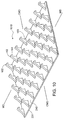
slots 70A andblades 60A are aligned in a transverse direction ofmold roll 55. This advantageously enablesmolding fastener elements 162 having crook portions facing in a cross-machine direction CMD (i.e., transverse tomold roll 55 and perpendicular to the machine direction MD), as shown in Figs. 9 and 10. Such orientation can be useful for resisting loads applied in a cross-machine direction, such as when the fastener tape is secured across a diaper tab, for example. However, it should be noted thatslots 70A andblades circumferential surface 65. For example, they may be aligned in machine direction MD or in a direction intermediary to machine direction MD and cross-machine direction CMD. Furthermore,cavities 130 may be aligned in various other configurations withinblades - Referring to Fig. 11, another
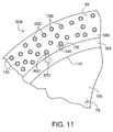
molding apparatus 50B includes amold roll 55B and multiple inserts or plugs 60D retained therein.Mold roll 55B comprises asleeve 165, which defines an array ofbores 70B.Bores 70B extend fromcircumferential surface 65 to aninner surface 170 ofsleeve 165.Bores 70B may be of various shapes and sizes corresponding to the shapes and sizes ofplugs 60D.Bores 70B may be created using any of various suitable methods. For example, bores 70B may be created using drilling, etching, or EDM techniques.Bores 70B are particularly small in diameter. For example, bores 70B can have a diameter of about 1.25 millimeters to about 6.35 millimeters. -
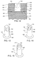
Plugs 60D may be retained withinbores 70B in any of various orientations, which allows for great versatility in the orientation of fastener elements produced.Plugs 60D may be oriented to produce fastener elements having crook portions facing in one or more desired directions.Plugs 60D can have a diameter of between about 1.25 millimeters to about 6.35 millimeters. Several suitable methods of retaining plugs 60D within bores 70B may be used. For example, as shown in Fig. 12, plug 60D includes acylindrical shank 175 with aflange 180 at one end.Bore 70B is comprised of acentral portion 185 and a recessedportion 190. Central and recessedportions bore 70B conform withshank 175 andflange 180 ofplug 60D.Plug 60D may be inserted intobore 70B from the direction ofinner surface 170 such thatshank 175 ofplug 60D sits withincentral portion 185 ofbore 70 andflange 180 ofplug 60D sits within recessedportion 190 ofbore 70B.Sleeve 165 is disposed around amandrel 195 such thatmandrel 195 abuts abottom surface 200 ofplug 60D, while thesecond portion 180 ofplug 60D abuts a recessedinner surface 205 ofsleeve 165. Thus, plug 60D is firmly compressed betweenmandrel 195 andsleeve 165, and thereby retained withinbore 70B. - Referring again to Fig. 11,
molding cavities 130 are defined betweenplug 60D andmold roll 55B. Material may be removed fromplug 60D using any of the suitable methods discussed above in order to create recesses such thatmold roll 55B, in the areas of those recesses, partially definecavities 130.Cavities 130 become fully defined upon insertingplug 60D intobore 70B. - As shown in Figs. 13,
multiple molding cavities 130 are arranged along aperimeter surface 210 ofplug 60D. Allcavities 130 face clockwise aboutplug 60D, as viewed from the mold roll surface. This enables the molding of a group of fastener elements having crooks oriented in different directions. As a result,fastener product 161C, which provides substantially equal peel and shear resistance in multiple directions, is produced (shown in Fig. 16). As the number of cavities facing in any one direction increases, the amount of peel and shear resistance in that direction also increases. - While the plug shown in Fig. 13, includes four
molding cavities 130 that are substantially equally spaced about the circumference of the plug, it should be appreciated that the plug may include more than four molding cavities (e.g., six molding cavities or more). As the number of molding cavities per plug increases, the number of directions in which the resulting product provides peel and sheer resistance can also increase. - Referring to Fig. 14, plug 60E includes two partially defined
molding cavities 130.Molding cavities 130 are aligned opposite one another at twoperimeter portions plug 60E. Both ofcrook portions 140 face in a clockwise direction aboutplug 60E, as viewed from the mold roll surface.Plug 60E, for example, can be used to produce a fastener product with substantially equal peel and shear resistance in opposite directions (similar to the product shown in Fig. 9). In certain embodiments, the opposite molding cavities can be arranged about the plug such that the crook portion of one molding cavity faces in the counterclockwise direction while the crook portion of the other molding cavity faces in the clockwise direction. This configuration enables the molding of a fastener product that provides peel and shear resistance in substantially only one direction (similar to the product shown in Fig. 10). In certain embodiments, twocavities 130 may be spaced apart circumferentially by about 90 degrees to produce a fastener product that provides peel and shear resistance in a longitudinal direction and in a lateral direction. - As shown in Fig. 15, plug 60F may completely define molding cavity 30.
Plug 60F is comprised of two halves, afirst half 213 and asecond half 214. Material is removed from one or bothhalves cavity 130 is defined whenhalves bore 70B.Plug 60F is preferably press-fitted withinbore 70B in a manner that preventshalves halves - In any of the embodiments discussed above, plugs 60D, 60E, 60F may be secured in corresponding
bores 70B in any rotational orientation. As aresult molding cavities 130 may be oriented in any direction relative to the machine direction of processing. Thus, fastener elements orientated in various directions with respect to a fastener product base can advantageously be produced. - Examples of related molding devices and molding methods are described in U.S. Pat. No. 4,794,028 issued to Fisher ("Fisher"). Fisher, for example, discloses a mold roll that includes a drum surrounded by an alternating series of ring-like etched plates and backing plates. The etched plates cooperate with the backing plates to form multiple molding cavities that extend inwardly from the circumferential surface of the mold roll. Fisher further describes positioning the mold roll adjacent an pressure roll and introducing molten resin therebetween to continuously mold a fastener product with multiple fastener elements. The mold roll (e.g., the drum of the mold roll) is described as having coolant circulated therethrough to remove heat from the etched plates and backing plates. The coolant can help to solidify the molten resin within the molding cavities to form the fastener elements. U.S. Pat. No. 5,971,738 issued to Jens et al. ("Jens") similarly describes examples of molding devices and methods. Jens, for example, describes a mold roll that includes a a drum surrounded by an alternating series of ring-like etched plates and backing plates. The plates include fluid passages extending therethrough in order to cool the plates and help solidify the resin within molding cavities formed by the plates. Other examples of molding devices, molding methods, and molded fastener products are described in U.S. Pat. No. 6,202,260 issued to Clune et al.
- A number of embodiments of the invention have been described. Nevertheless, it will be understood that various modifications may be made without departing from the spirit and scope of the invention.
Claims (22)
- A molding apparatus for forming a sheet-form fastener product, the molding apparatus comprising:a mold roll (55; 55A; 55B) rotatable about an axis of rotation (75) and having a circumferential surface (65) defining a plurality of apertures (70; 70A; 70B) therein, the apertures (70; 70A; 70B) extending inward from the circumferential surface (65) of the mold roll (55; 55A; 55B); anda plurality of inserts (60; 60A; 60B; 60C; 60D; 60E), each insert having a first end and a second end, the inserts (60; 60A; 60B; 60C; 60D; 60E; 60F) being retained within corresponding apertures (70; 70A; 70B) of the mold roll (55; 55A; 55B) such that the first end of each insert is directed toward the circumferential surface (65) of the mold roll (55; 55A; 55B), the inserts (60; 60A; 60B; 60C; 60D; 60E) having surfaces at least partially defining blind molding cavities (130) shaped to mold, from molten resin forced into the molding cavities (130) from the circumferential surface (65) of the mold roll (55; 55A; 55B), an array of fastener elements (162) having overhanging heads for releasable engagement with a mating fastener product.
- The apparatus of claim 1, wherein the apertures (70; 70A) extend along the circumferential surface (65) of the mold roll (55; 55A) in a direction substantially parallel to the axis of rotation (75) of the mold roll (55; 55A) and/or the apertures (70; 70A) extend from a first side (80) of the mold roll (55; 55A) to a second side (85) of the mold roll (55; 55A).
- The apparatus of claim 1 or 2, wherein the molding cavities (130) are completely defined within the inserts (60; 60A; 60B; 60C).
- The apparatus of claim 1 or 2, wherein first molding cavities (130) are defined between first sides (145A) of the inserts (60; 60A; 60B; 60C) and the mold roll (55; 55A) and/or second molding cavities (130) are defined between second sides (150A) of the inserts (60; 60A; 60B; 60C) and the mold roll (55; 55A).
- The apparatus of claim 4, wherein at least some of the first molding cavities (130) include crook portions (140) and at least some of the second molding cavities (130) include crook portions (140).
- The apparatus of claim 5, wherein the crook portions (140) of the first molding cavities (130) face in a direction substantially opposite the crook portions (140) of the second molding cavities (130) and/or the crook portions (140) of the first and second molding cavities (130) face in a direction transverse to the mold roll (55; 55A).
- The apparatus of claim 1 or 2, wherein the molding cavities (130) extend from first sides (145B) of the inserts (60; 60A; 60B; 60C) to second sides (150B) of the inserts (60; 60A; 60B; 60C).
- The apparatus of any of the above claims, wherein the inserts (60; 60A; 60B; 60C) comprise an upper portion (90) and a lower portion (95), the lower portion (95) including a first segment (100) extending transversely beyond a first side (80) of the mold roll (55; 55A) and a second segment (105) extending transversely beyond a second side (85) of the mold roll (55; 55A).
- The apparatus of claim 8, further comprising a first retainer cap (110) secured to the first side (80) of the mold roll (55; 55A) and a second retainer cap (115) secured to the second side (85) of the mold roll (55; 55A), the retainer caps (110; 115) having inner portions conforming to the first and second segments (100; 105) of the inserts (60; 60A; 60B; 60C) to retain the inserts (60; 60A; 60B; 60C) within the apertures (70; 70A).
- The apparatus of claim 1, wherein the mold roll (55; 55B) comprises a sleeve (165) having an inner surface (170), the plurality of apertures (70; 70B) extending from the inner surface (170) of the sleeve (165) to the circumferential surface (65).
- The apparatus of claim 10, wherein the molding cavities (130) are completely defined within the inserts (60; 60D; 60E; 60F).
- The apparatus of claim 10, wherein the molding cavities (130) are defined by perimeter portions of the inserts (60; 60D; 60E; 60F) and the mold roll (55; 55B) and/or each of the molding cavities (130) includes a crook portion (140) extending in the same direction along the insert (60; 60D; 60E; 60F).
- The apparatus of claim 10, wherein multiple molding cavities (130) are defined by the perimeter portion of each insert (60; 60D; 60E; 60F) and the mold roll (55; 55B) and/or each of the molding cavities (130) includes a crook portion (140) extending in the same direction along the insert (60; 60D; 60E; 60F).
- The apparatus of claim 10, wherein a first molding cavity (130) is defined by a first perimeter portion (111) of each insert (60; 60D; 60E; 60F) and the mold roll (55; 55B), and a second molding cavity (130) is defined by a second perimeter portion (112) of each insert (60; 60D; 60E; 60F) and the mold roll (55; 55B), the second perimeter portion (112) being substantially opposite the first perimeter portion (111).
- The apparatus of claim 14, wherein the first molding cavity (130) and the second molding cavity (130) include crook portions (140), the crook portion (140) of the first molding cavity (130) facing in a direction along the insert (60; 60D; 60E; 60F) opposite the crook portion (140) of the second molding cavity (130).
- The apparatus of any of claims 10-15, wherein the mold roll (55; 55B) further comprises a mandrel (195), the sleeve (165) disposed around the mandrel (195).
- The apparatus of claim 16, wherein the inserts (60; 60D; 60E; 60F) comprise first portions and second portions, the first portions of the inserts (60; 60A; 60B; 60C; 60D; 60E) being positioned within first portions of the apertures (70; 70B), and the second portions of the inserts (60; 60D; 60E; 60F) being positioned within second portions of the apertures (70; 70B).
- The apparatus of claim 17, wherein the first portions of the inserts (60; 60D; 60E; 60F) and apertures (70; 70B) are substantially cylindrical and the second portions of the inserts (60; 60D; 60E; 60F) and apertures (70; 70B) are substantially disk-shaped, the second portions having a larger diameter than the first portions and/or bottom surfaces of the second portions of the inserts (60; 60D; 60E; 60F) are shaped to conform to the mandrel (195).
- The apparatus of any of the above claims, wherein the inserts (60; 60D; 60E; 60F) are configured to be positioned within the apertures (70; 70B) in any of a plurality of orientations.
- A method of producing a fastener product (161; 161A; 161B; 161C) having a multiplicity of fastener elements (162) extending from a base (240), the method comprising:providing a mold roll (55; 55A; 55B) having a circumferential surface (65) defining an array of apertures (70; 70A; 70B) therein, the apertures (70; 70A; 70B) extending inward from the circumferential surface (65);disposing inserts (60; 60A; 60B; 60C; 60D; 60E; 60F) within the apertures (70; 70A; 70B), the inserts (60; 60A; 60B; 60C; 60D; 60E; 60F) having surfaces at least partially defining blind molding cavities (130);introducing molten resin (235) to the circumferential surface (65) of the mold roll (55; 55A; 55B) under pressure conditions and forcing some of the resin (235) into the molding cavities (130) to mold an array of fastener elements (162) integrally with resin disposed at the circumferential surface (65) of the mold roll (55; 55A; 55B); and then stripping the resin from the mold roll (55; 55A; 55B).
- The method of claim 20, wherein the resin is introduced into a nip (N) defined by the mold roll (55; 55A; 55B) and an adjacent pressure device (225; 220).
- The method of claim 20 or 21, further comprising securing a first retainer cap (110) to the first side (80) of the mold roll (55; 55A), and securing a second retainer cap (11) to the second side (85) of the mold roll (55; 55A), the retainer caps (110; 111) having inner portions conforming to the first and second segments (100; 105) of the inserts (60; 60A; 60B; 60C) to retain the inserts (60; 60A; 60B; 60C) within the apertures (70; 70A).
Applications Claiming Priority (1)
| Application Number | Priority Date | Filing Date | Title |
|---|---|---|---|
| US10/952,104 US7192266B2 (en) | 2004-09-28 | 2004-09-28 | Molding device inserts |
Publications (2)
| Publication Number | Publication Date |
|---|---|
| EP1640133A1 true EP1640133A1 (en) | 2006-03-29 |
| EP1640133B1 EP1640133B1 (en) | 2008-09-17 |
Family
ID=35432065
Family Applications (1)
| Application Number | Title | Priority Date | Filing Date |
|---|---|---|---|
| EP05021168A Expired - Fee Related EP1640133B1 (en) | 2004-09-28 | 2005-09-28 | Moulding device with inserts for a fastener and method for producing said fastener |
Country Status (5)
| Country | Link |
|---|---|
| US (2) | US7192266B2 (en) |
| EP (1) | EP1640133B1 (en) |
| CN (1) | CN1754673B (en) |
| DE (1) | DE602005009775D1 (en) |
| ES (1) | ES2313176T3 (en) |
Cited By (2)
| Publication number | Priority date | Publication date | Assignee | Title |
|---|---|---|---|---|
| WO2009011943A1 (en) * | 2007-07-16 | 2009-01-22 | Velro Industries B.V. | Apparatus and method for making touch fastener products |
| WO2014174110A1 (en) * | 2013-04-26 | 2014-10-30 | Darvan Invest N.V. | Method and device for producing a plastics band with projections, and a plastics band thus produced |
Families Citing this family (7)
| Publication number | Priority date | Publication date | Assignee | Title |
|---|---|---|---|---|
| CA2316587C (en) | 2000-08-14 | 2009-12-01 | Charles M. Schmeichel | Tonneau cover having rear bar lock |
| US7641469B2 (en) * | 2004-09-28 | 2010-01-05 | Velcro Industries B.V. | Fastener molding |
| JP5148622B2 (en) * | 2006-11-10 | 2013-02-20 | ザ プロクター アンド ギャンブル カンパニー | Method for forming with rotary press |
| US7815239B1 (en) | 2007-10-26 | 2010-10-19 | Agri-Cover, Inc. | Tonneau cover assemblies |
| US8857887B1 (en) | 2011-08-31 | 2014-10-14 | Agri-Cover, Inc. | Tonneau cover having magnetic fasteners |
| WO2019011524A1 (en) | 2017-07-11 | 2019-01-17 | Velcro BVBA | Forming fastener elements |
| CN112223656A (en) * | 2020-09-10 | 2021-01-15 | 武汉艾络特科技有限公司 | Injection mold is used in production of cell-phone shell with cooling body |
Citations (2)
| Publication number | Priority date | Publication date | Assignee | Title |
|---|---|---|---|---|
| US4794028A (en) * | 1984-04-16 | 1988-12-27 | Velcro Industries B.V. | Method for continuously producing a multi-hook fastner member and product of the method |
| US5167895A (en) * | 1990-01-05 | 1992-12-01 | Agru Alois Gruber Gmbh | Method of manufacturing elastic nub panel produced thereby |
Family Cites Families (24)
| Publication number | Priority date | Publication date | Assignee | Title |
|---|---|---|---|---|
| US3507010A (en) * | 1967-07-03 | 1970-04-21 | Monsanto Co | Continuous molding of thermoplastic materials |
| US3590109A (en) * | 1967-07-03 | 1971-06-29 | Monsanto Co | Continuous molding of thermoplastic materials |
| US3762000A (en) * | 1971-11-11 | 1973-10-02 | M Menzin | Production of a continuous molded plastic strip |
| DE2949251C2 (en) * | 1979-12-07 | 1984-02-23 | Skf Kugellagerfabriken Gmbh, 8720 Schweinfurt | Device for removing partial slides from an injection or casting mold for cages for cylindrical rolling elements |
| US5900350A (en) | 1996-06-06 | 1999-05-04 | Velcro Industries B.V. | Molding methods, molds and products |
| DE19646318A1 (en) * | 1996-11-09 | 1998-05-14 | Binder Gottlieb Gmbh & Co | Efficient process for the production of an adhesive closure part from thermoplastic plastic |
| US6039556A (en) | 1997-01-21 | 2000-03-21 | Velcro Industries B.V. | Stackable mold plates having arrays of laser-cut mold surfaces at their edges |
| US6930277B2 (en) | 1997-09-10 | 2005-08-16 | Velcro Industries B.V. | Fastener element molding |
| US5971738A (en) | 1997-01-21 | 1999-10-26 | Velcro Industries B.V. | Continuous molding of fasteners and other features |
| US5980230A (en) | 1997-04-11 | 1999-11-09 | Velcro Industries B.V. | Forming fastener products |
| US6280670B1 (en) | 1997-08-22 | 2001-08-28 | Velcro Industries B.V. | Post- forming heads on fastener elements |
| US6099289A (en) | 1997-08-25 | 2000-08-08 | Velcro Industries B.V. | Forming mold cavities |
| US6432339B1 (en) * | 1997-08-25 | 2002-08-13 | Velcro Industries B.V. | Continuous molding of fastener products with a mold belt |
| US6258311B1 (en) | 1997-08-25 | 2001-07-10 | Velcro Industries B.V. | Forming mold cavities |
| US5875527A (en) | 1997-08-29 | 1999-03-02 | Velcro Industries B.V. | Fastener element arrangement |
| US5922222A (en) | 1997-09-23 | 1999-07-13 | Velcro Industries B.V. | Forming fastener mold cavities by electro-discharge machining |
| US6202260B1 (en) | 1998-11-06 | 2001-03-20 | Velcro Industries B.V. | Touch fasteners their manufacture and products incorporating them |
| US6190594B1 (en) * | 1999-03-01 | 2001-02-20 | 3M Innovative Properties Company | Tooling for articles with structured surfaces |
| FR2791873B1 (en) | 1999-04-07 | 2001-08-03 | Aplix Sa | OBLONG STRIP FORMING MALE SELF-GRIPPING PART, CYLINDER TO BE FORMED FOR ITS MANUFACTURE AND METHOD FOR MANUFACTURING A STRIP OF THE SAME |
| KR100587947B1 (en) * | 1999-10-19 | 2006-06-08 | 알로아 그루버 게엠베하 | Method and device for producing synthetic panels with undercut, one-piece extensions and a synthetic panel of this type |
| ES2307601T3 (en) | 2000-03-14 | 2008-12-01 | Velcro Industries B.V. | PROCEDURE FOR THE FORMATION OF AN EXTENSIBLE FIXATION. |
| DE60132310T2 (en) | 2000-03-14 | 2009-01-02 | Velcro Industries B.V. | VELCRO SYSTEM |
| US6640348B1 (en) | 2000-11-09 | 2003-11-04 | Velcro Industries B.V. | Forming continuous fastener material |
| US6902389B2 (en) * | 2003-05-14 | 2005-06-07 | 3M Innovative Properties Company | Wire wound tooling |
-
2004
- 2004-09-28 US US10/952,104 patent/US7192266B2/en not_active Expired - Fee Related
-
2005
- 2005-09-28 EP EP05021168A patent/EP1640133B1/en not_active Expired - Fee Related
- 2005-09-28 ES ES05021168T patent/ES2313176T3/en active Active
- 2005-09-28 DE DE602005009775T patent/DE602005009775D1/en active Active
- 2005-09-28 CN CN2005101165248A patent/CN1754673B/en not_active Expired - Fee Related
-
2006
- 2006-10-12 US US11/546,821 patent/US20070029695A1/en not_active Abandoned
Patent Citations (2)
| Publication number | Priority date | Publication date | Assignee | Title |
|---|---|---|---|---|
| US4794028A (en) * | 1984-04-16 | 1988-12-27 | Velcro Industries B.V. | Method for continuously producing a multi-hook fastner member and product of the method |
| US5167895A (en) * | 1990-01-05 | 1992-12-01 | Agru Alois Gruber Gmbh | Method of manufacturing elastic nub panel produced thereby |
Cited By (4)
| Publication number | Priority date | Publication date | Assignee | Title |
|---|---|---|---|---|
| WO2009011943A1 (en) * | 2007-07-16 | 2009-01-22 | Velro Industries B.V. | Apparatus and method for making touch fastener products |
| US7806677B2 (en) | 2007-07-16 | 2010-10-05 | Velcro Industries B.V. | Molding apparatus and related systems and methods |
| WO2014174110A1 (en) * | 2013-04-26 | 2014-10-30 | Darvan Invest N.V. | Method and device for producing a plastics band with projections, and a plastics band thus produced |
| BE1021424B1 (en) * | 2013-04-26 | 2015-11-19 | Darvan Invest N.V. | METHOD AND APPARATUS FOR MANUFACTURING A PLASTIC TAPE WITH PROTECTION |
Also Published As
| Publication number | Publication date |
|---|---|
| EP1640133B1 (en) | 2008-09-17 |
| CN1754673B (en) | 2010-12-01 |
| US20060066002A1 (en) | 2006-03-30 |
| US20070029695A1 (en) | 2007-02-08 |
| ES2313176T3 (en) | 2009-03-01 |
| US7192266B2 (en) | 2007-03-20 |
| DE602005009775D1 (en) | 2008-10-30 |
| CN1754673A (en) | 2006-04-05 |
Similar Documents
| Publication | Publication Date | Title |
|---|---|---|
| EP1640133B1 (en) | Moulding device with inserts for a fastener and method for producing said fastener | |
| US7217119B2 (en) | Fastener molding | |
| AU592816B2 (en) | Separable fastener member and method and apparatus for producing same | |
| US4794028A (en) | Method for continuously producing a multi-hook fastner member and product of the method | |
| EP0640033B1 (en) | Interengaging fastener member and method of making same | |
| EP1060068B1 (en) | Post-forming heads on fastener elements | |
| EP1304941B1 (en) | Segmented separable fastener | |
| WO2001056761A1 (en) | Touch fasteners and method of making same | |
| US20040094860A2 (en) | Continuous molding of fastener products with a mold belt | |
| EP1019229B1 (en) | Method of making a mould from mould plates and a mould plate formed from flat plate stock | |
| EP3651605B1 (en) | Forming fastener elements | |
| EP1689259B1 (en) | Multiple-crook male touch fastener elements | |
| EP1616656B1 (en) | A hook fastening element for a hook and loop fastening element | |
| US7641469B2 (en) | Fastener molding | |
| JP2010523237A (en) | Method for producing plastic adhesive fastener element and instrument for carrying out the method | |
| US7806677B2 (en) | Molding apparatus and related systems and methods |
Legal Events
| Date | Code | Title | Description |
|---|---|---|---|
| PUAI | Public reference made under article 153(3) epc to a published international application that has entered the european phase |
Free format text: ORIGINAL CODE: 0009012 |
|
| 17P | Request for examination filed |
Effective date: 20051013 |
|
| AK | Designated contracting states |
Kind code of ref document: A1 Designated state(s): AT BE BG CH CY CZ DE DK EE ES FI FR GB GR HU IE IS IT LI LT LU LV MC NL PL PT RO SE SI SK TR |
|
| AX | Request for extension of the european patent |
Extension state: AL BA HR MK YU |
|
| AKX | Designation fees paid |
Designated state(s): DE ES GB |
|
| GRAP | Despatch of communication of intention to grant a patent |
Free format text: ORIGINAL CODE: EPIDOSNIGR1 |
|
| GRAS | Grant fee paid |
Free format text: ORIGINAL CODE: EPIDOSNIGR3 |
|
| GRAA | (expected) grant |
Free format text: ORIGINAL CODE: 0009210 |
|
| AK | Designated contracting states |
Kind code of ref document: B1 Designated state(s): DE ES GB |
|
| REG | Reference to a national code |
Ref country code: GB Ref legal event code: FG4D |
|
| REF | Corresponds to: |
Ref document number: 602005009775 Country of ref document: DE Date of ref document: 20081030 Kind code of ref document: P |
|
| PGFP | Annual fee paid to national office [announced via postgrant information from national office to epo] |
Ref country code: ES Payment date: 20080926 Year of fee payment: 4 |
|
| REG | Reference to a national code |
Ref country code: ES Ref legal event code: FG2A Ref document number: 2313176 Country of ref document: ES Kind code of ref document: T3 |
|
| PLBE | No opposition filed within time limit |
Free format text: ORIGINAL CODE: 0009261 |
|
| STAA | Information on the status of an ep patent application or granted ep patent |
Free format text: STATUS: NO OPPOSITION FILED WITHIN TIME LIMIT |
|
| 26N | No opposition filed |
Effective date: 20090618 |
|
| GBPC | Gb: european patent ceased through non-payment of renewal fee |
Effective date: 20090928 |
|
| PG25 | Lapsed in a contracting state [announced via postgrant information from national office to epo] |
Ref country code: GB Free format text: LAPSE BECAUSE OF NON-PAYMENT OF DUE FEES Effective date: 20090928 |
|
| REG | Reference to a national code |
Ref country code: ES Ref legal event code: FD2A Effective date: 20111116 |
|
| PG25 | Lapsed in a contracting state [announced via postgrant information from national office to epo] |
Ref country code: ES Free format text: LAPSE BECAUSE OF NON-PAYMENT OF DUE FEES Effective date: 20090929 |
|
| REG | Reference to a national code |
Ref country code: DE Ref legal event code: R082 Ref document number: 602005009775 Country of ref document: DE Representative=s name: MUELLER-BORE & PARTNER PATENTANWAELTE PARTG MB, DE Ref country code: DE Ref legal event code: R081 Ref document number: 602005009775 Country of ref document: DE Owner name: VELCRO BVBA, BE Free format text: FORMER OWNER: VELCRO INDUSTRIES B.V. (NL), CURACAO, AN |
|
| PGFP | Annual fee paid to national office [announced via postgrant information from national office to epo] |
Ref country code: DE Payment date: 20170927 Year of fee payment: 13 |
|
| REG | Reference to a national code |
Ref country code: DE Ref legal event code: R119 Ref document number: 602005009775 Country of ref document: DE |
|
| PG25 | Lapsed in a contracting state [announced via postgrant information from national office to epo] |
Ref country code: DE Free format text: LAPSE BECAUSE OF NON-PAYMENT OF DUE FEES Effective date: 20190402 |