EP1641361B1 - Communications device for a protective helmet - Google Patents
Communications device for a protective helmet Download PDFInfo
- Publication number
- EP1641361B1 EP1641361B1 EP04777047A EP04777047A EP1641361B1 EP 1641361 B1 EP1641361 B1 EP 1641361B1 EP 04777047 A EP04777047 A EP 04777047A EP 04777047 A EP04777047 A EP 04777047A EP 1641361 B1 EP1641361 B1 EP 1641361B1
- Authority
- EP
- European Patent Office
- Prior art keywords
- ratchet sleeve
- microphone
- helmet
- headband
- user
- Prior art date
- Legal status (The legal status is an assumption and is not a legal conclusion. Google has not performed a legal analysis and makes no representation as to the accuracy of the status listed.)
- Active
Links
- 230000001681 protective effect Effects 0.000 title abstract description 18
- 210000000988 bone and bone Anatomy 0.000 claims abstract description 57
- 230000000284 resting effect Effects 0.000 claims description 6
- 230000007423 decrease Effects 0.000 claims description 5
- 239000002991 molded plastic Substances 0.000 claims description 2
- ZLGYJAIAVPVCNF-UHFFFAOYSA-N 1,2,4-trichloro-5-(3,5-dichlorophenyl)benzene Chemical compound ClC1=CC(Cl)=CC(C=2C(=CC(Cl)=C(Cl)C=2)Cl)=C1 ZLGYJAIAVPVCNF-UHFFFAOYSA-N 0.000 description 13
- 239000012528 membrane Substances 0.000 description 4
- 230000005540 biological transmission Effects 0.000 description 3
- 239000000463 material Substances 0.000 description 3
- 238000010276 construction Methods 0.000 description 2
- 239000004033 plastic Substances 0.000 description 2
- 239000000725 suspension Substances 0.000 description 2
- 210000001260 vocal cord Anatomy 0.000 description 2
- 239000000853 adhesive Substances 0.000 description 1
- 230000001070 adhesive effect Effects 0.000 description 1
- 239000003990 capacitor Substances 0.000 description 1
- 239000004020 conductor Substances 0.000 description 1
- 230000003247 decreasing effect Effects 0.000 description 1
- 238000010586 diagram Methods 0.000 description 1
- 238000000034 method Methods 0.000 description 1
- 230000001012 protector Effects 0.000 description 1
- 230000002441 reversible effect Effects 0.000 description 1
Images


Classifications
-
- A—HUMAN NECESSITIES
- A42—HEADWEAR
- A42B—HATS; HEAD COVERINGS
- A42B3/00—Helmets; Helmet covers ; Other protective head coverings
- A42B3/04—Parts, details or accessories of helmets
- A42B3/10—Linings
- A42B3/14—Suspension devices
-
- A—HUMAN NECESSITIES
- A42—HEADWEAR
- A42B—HATS; HEAD COVERINGS
- A42B3/00—Helmets; Helmet covers ; Other protective head coverings
- A42B3/04—Parts, details or accessories of helmets
- A42B3/30—Mounting radio sets or communication systems
Definitions
- the present invention relates to a helmet having a communication device.
- Bone conduction microphones are known in the art and are used in communication systems for the transmission of speech. When a person speaks, the cranial bones vibrate in accordance with the sounds that are produced by the person's vocal cords. Bone conduction microphones detect vibrations in the user's cranial bones and convert the vibrations to electrical signals that can be communicated to a two-way radio. Bone conduction microphones are especially useful in noisy environments such as, for example, in helicopters, at fire stations, at construction sites, etc., where typical microphones may pick up and transmit a significant amount of ambient noise. Many of these environments require a user to wear a protective helmet that has an adjustable headband.
- Bone conduction microphones must firmly engage or abut the bone through which the vibrations are traveling for the bone conduction microphone to consistently and reliably detect the vibrations and convert the detected vibrations to electrical signals.
- the assembly of the '249 patent includes a sliding mechanism that must be closed around a ratchet sleeve, carried on the helmet's napestrap.
- a ratchet sleeve is a sleeve carried by the napestrap portion of the headband.
- the ratchet sleeve has an adjustable knob that rotates to increase/decrease the size of the headband.
- a screw mechanism must be tightened to secure the assembly to the ratchet sleeve.
- the microphone is on a separate adjustable flange and must be adjusted to fit the user's head, and a screw mechanism needs to be tightened to retain the microphone in its adjusted position.
- these devices do not place the microphone in an optimal position to consistently and reliably detect the vibrations in the cranial bones. Further, the position of the microphone may need to be adjusted during use, which is impossible, or at least very inconvenient, in many circumstances, such as while fighting a fire, or in the middle of a rescue attempt. In addition, it is not easy and/or convenient to secure these devices to a helmet. Finally, these devices limit the placement of a speaker to one side of the helmet.
- a helmet having a communication device comprising:
- the headband comprises a napestrap having said ratchet sleeve.
- the support may be configured so that the device can be mounted on the ratchet sleeve in its use position without adjustment of moveable parts.
- the support may comprise an upper support flange for resting on the top edge of the ratchet sleeve so that the weight of the device is supported on the top edge of the ratchet sleeve while the ratchet sleeve simultaneously secures the microphone in direct engagement with the user's head in use of the device.
- the support may comprise: an upper support flange for resting on the top edge of the ratchet sleeve; and a lower support flange for positioning below the lower edge of the ratchet sleeve, the microphone, upper support flange and lower support flange together defining a U-shaped channel for receiving the ratchet sleeve.
- the support may be made from a single piece of molded plastic.
- the helmet could further comprise an electronics housing carried by the upper support flange of the support.
- the support may be configured to position the microphone at or near the center of the back of the user's head, the electronics housing being positioned to the side of the microphone.
- the electronics housing could be spaced rearwardly with respect to the microphone by a distance sufficient so that the ratchet sleeve can be slipped between the microphone and the electronics housing for mounting the device on the ratchet sleeve.
- the electronics housing could be shaped and positioned to the side of the microphone in such a way that the device can be mounted on the ratchet sleeve in two different configurations, a first configuration with the electronics housing on the user's left side, and a second configuration with the electronics housing on the user's right side, the device being adapted for mounting in one of these configurations by slipping the device over the top edge of the ratchet sleeve and being adapted for mounting in the other configuration by slipping the device over the lower edge of the ratchet sleeve.
- the helmet could further comprise a speaker for positioning near the ear of the user, and a flexible boom mounting the speaker to the electronics housing.
- the support may comprise an upper support flange for resting on the top edge of the ratchet sleeve so that the weight of the device is supported on the top edge of the ratchet sleeve, the ratchet sleeve being configured to place the microphone in direct engagement with the user's head while the device is in use.
- the support could further comprise a lower support flange, the upper support flange, the microphone and the lower support flange forming a generally U-shaped channel for receiving the ratchet sleeve.
- the support may be configured so that the device can be mounted on the ratchet sleeve in its use position without adjustment of moveable parts.
- the helmet could then further comprise a speaker, the speaker being supported by the upper support flange, and the speaker being spaced rearwardly with respect to the microphone by a distance sufficient so that the ratchet sleeve can be slipped between the microphone and the speaker.
- the helmet could further comprise a flexible boom, the flexible boom connecting the speaker to the upper support flange.
- the communication system 100 includes a radio transmitter/receiver 102 electrically coupled to a printed circuit board (PCB) 120 via cable 110.
- PCB 120 is electrically coupled to a bone conduction microphone 104 and a speaker assembly 108 via cables 112, 114 respectively.
- the bone conduction microphone 104 and speaker 108 are placed in circuit communication with the radio transmitter/receiver 102.
- an optional auxiliary microphone 130 such as a push-to-talk (PIT) microphone, a lapel microphone (LM),etc. is shown.
- PIT push-to-talk
- LM lapel microphone
- the bone conduction microphone 104 detects and amplifies the vibrations in the cranial bones.
- the bone conduction microphone 104 is made up of a vibration sensor (not shown) and electrical circuitry.
- the electrical circuitry can be located integral with the vibration sensor or remote from the vibration sensor. Preferably the electrical circuitry is located on PCB 120, or in circuitry located in the optional auxiliary microphone.
- the vibrations are detected and converted into electrical signals that are representative of the user's voice.
- the electrical signals can be communicated to the radio transmitter/receiver via cable 112 and PCB 120 where the electrical signals can be transmitted to a second radio receiver (not shown).
- a bone conduction microphone is disclosed in U.S. Pat. No. 5,054,079 . Other bone conduction microphones can also be used.
- Electrical signals received by the radio transmitter/receiver 102 can be communicated to the speaker assembly 108 via cable 110, PCB 120 and cable 114.
- the electrical signals communicated to the speaker assembly 108 cause a membrane (not shown) inside the speaker to vibrate.
- the vibrations in the membrane produce an aural transmission within the frequency range detectable by the user.
- the aural transmissions are representative of a human voice.
- the communication device can be used with any helmet that has a headband.
- the helmet is a protective helmet, such as a fireman's helmet, a construction hardhat, etc.
- Figure 1B illustrates a typical protective helmet 150.
- the protective helmet 150 includes a shell 152, a suspension harness 154, a headband 170 having a napestrap portion 165, and a ratchet sleeve 160.
- the shell 152 provides protection from falling objects and is secured to the user's head by the headband 170.
- the headband 170 which surrounds a user's head, is connected to the shell 152 via the suspension harness 154.
- the headband 170 is adjustable.
- the headband 170 has a first adjustment strap 170A and a second adjustment strap 170B.
- the adjustment straps 170A, 170B are located in the back of the helmet 150 and form part of the napestrap 165.
- the portion of the headband 170 engaging the lower rear portion of the user's head at or near the nape of the user's neck is referred to herein as the napestrap 165.
- the adjustment straps 170A and 170B allow the size of the headband 170 to be changed.
- the headband 170 may be adjusted in any known manner, such as with one or more projecting members or tabs (not shown) on adjustment strap 170a that can be inserted into a one or more holes (not shown), in a series of holes, on adjustment strap 170B, similar to the adjustment of a napestrap commonly used on baseball caps.
- the napestrap has a ratchet sleeve 160 ( Figure 1C ), carried by the napestrap 165 and described in more detail below, for easily adjusting the size of the headband 170.
- the headband 170 for use with a ratchet sleeve 160 has a first adjustment strap 170A and a second adjustment strap 170B.
- the adjustment straps 170A, 170B overlap inside of the ratchet sleeve 160.
- the ratchet sleeve 160 has an adjustment knob 162 that rotates inside the ratchet sleeve 160 and engages adjustment straps 170A and 170B. Rotating the adjustment knob 162 in one direction decreases the size of the headband 170 by pulling adjustment straps 170A and 170B into the ratchet sleeve 160. Rotating the adjustment knob 162 in the opposite direction increases the size of the headband 170 by pushing the adjustment straps 170A and 170B out of the ratchet sleeve 160.
- headbands are made of relatively flexible rigid plastic material having a rectangular configuration.
- the rectangular configuration has a first dimension, typically between 1.91 cm and 2.54 cm (3 ⁇ 4" and 1") and a second dimension, typically around 1.59 mm (1/16").
- the rectangular configuration allows the headband 170 to be rigid in one direction and be flexible in the other direction enabling it to roughly conform to the shape of the user's head.
- the ratchet sleeve 160 is made of relatively rigid plastic that is curved slightly, roughly proportional to the curve of a typical user's head.
- the ratchet sleeve 160 while fairly rigid, also conforms to a user's head. While the headband 170 is flexible in a first direction, it is rigid in the second direction.
- the headband provides a desirable support for mounting a bone conduction microphone having the weight of the bone conduction microphone and its support carried by the headband.
- the communication device 200 includes a support member 201, a bone conduction microphone 207, a speaker assembly 108 connected to the support member 201 via a flexible boom 224, and a cable 220 for placing the communication device 200 in circuit communication with a radio transmitter/receiver (not shown).
- the flexible boom 224 can be made up of any flexible material, such a flexible conduit, rubber, multiconductor wire, etc. Preferably, however, the flexible boom 224 is hollow member to facilitate the passage of the electrical conductors required for the speaker.
- the support member 201 is used to releasably mount the bone conduction microphone 207 to the headband 170 of the helmet.
- the support member 201 includes a support plate 202, an upper flange 204, a lower flange 206, a plurality of tabs 212, and an electronics housing 210.
- the upper support flange 204 and lower flange 206 are attached to opposite sides of the support plate 202.
- the support flanges 204, 206 are connected directly to the microphone 207 and the support plate 202 is not required.
- the support flanges 204 and 206 are substantially perpendicular to the support plate 202 forming a generally U-shaped channel.
- the U-shaped channel is curved slightly to conform to the general shape of the napestrap 165 and/or ratchet sleeve 160.
- the upper and lower flanges 204,206, respectively, are configured to extend over a top edge and a bottom edge of napestrap 165 ( Figures 3D and 4 ) to facilitate securing the communication device to the napestrap 165.
- the napestrap 165 supports the weight of the communication device 200 when the communication device 200 is mounted on the napestrap 165.
- the support member 201 positions the microphone 207 between the napestrap 165 and the user's head 307. Securing the communication device 200 to the napestrap 165 will be described in more detail below.
- the support plate 202 and support flanges 204,206 are curved slightly to conform to the general shape of a napestrap 165 in a protective helmet 150.
- the lower flange 206 and upper flange 204 have a plurality of tabs 212A, 212B, 212C, 212D located opposite the support plate 202 so that the tabs 212 A-D extend perpendicular to the lower flange 206 and upper flange 204.
- the tabs 212 A-D When mounted on the napestrap 165, the tabs 212 A-D extend upwardly from the lower flange 206 and downwardly from the upper flange 204 in the back of the napestrap 165 and aid in the securing the support member 201 to the napestrap 165.
- the upper flange 204 is configured to carry the electronics housing 210.
- the upper flange 204 extends beyond the end of the support plate 202, in the direction of speaker 108 and carries or supports the electronics housing 210.
- electronics housing 210 has a face plate 214 that extends from the upper flange 204 to approximately the bottom of support plate 202.
- the face plate 214 is substantially parallel to the support plate 202 (see Figure 2 ). It should be noted that since the support plate 202 is slightly curved, the face plate 214 is not literally parallel to the support plate 202.
- the electronics housing 210 is spaced rearwardly with respect to the microphone 207 by a distance sufficient so that the napestrap 165 can be slipped between the microphone 207 and the electronics housing 210.
- the electronics housing 210 is configured to receive a radio interface cable 220 and a flexible boom 224.
- the radio interface cable 220 has a cable connector 222 for connection to a radio transmitter/receiver (not shown) on a first end and a cable strain relief connector 218 located near the second end.
- the cable strain relief connector 218 is secured to the electronics housing 210.
- the radio interface cable 220 is electrically coupled to PCB 120, which is located in electronics housing 210.
- PCB 120 is also coupled to the speaker assembly 108 through wires (not shown) that are housed in the flexible boom 224.
- the bone conduction microphone 207 is made up of a vibration sensing device 420 ( Figure 4 ) that is encased in a sensing element cavity 208, and electrical circuitry located on PCB 120.
- the sensing element cavity 208 provides a soft surface for contacting a user's head 307. The soft surface provides comfort during long periods of use.
- the sensing element cavity 208 provides a medium for conducting the vibrations traveling through the cranial bones to the vibration sensing device 420.
- the sensing element cavity 208 is secured to the front of the support plate 202.
- the support plate 202 has an aperture through it and the sensing element cavity 208 is inserted therethrough.
- a back cover 302 ( Figure 3C ) is utilized to secure the sensing element cavity 208 in place and to protect the wiring that extends out of the back of the sensing element cavity 208.
- the sensing element cavity 208 can be protected by a rubber pad, wherein the rubber pad is configured to contact the user's head 307 and provide a layer of protection for the sensing element cavity 208.
- the U-shaped channel support member 201 and the electronics housing 210 form an aperture to receive headband 170, napestrap 165, and/or ratchet sleeve 160 ( Fig. 1B ) therethrough.
- the weight of the communication device 200, the upper flange 204, and the electronics housing 210 service to releasably mount the communication device 200 to the napestrap 165.
- the tabs 212 A-D located on the lower flange 206 and upper flange 204 extend upwardly and downwardly, respectively, in the back of the napestrap 165, and function to aid in releasably mounting the device to the napestrap 165.
- the pressure applied to the communication device 200 while in use, with the microphone 207 positioned between a user's head 307 and the napestrap 165, further acts to securely hold the communication device 200 in place.
- the bone conduction microphone 207 can be positioned in a plurality of locations so that during use the bone conduction microphone 207 is between the napestrap 165 and the user's head 307.
- the device positions the bone conduction microphone 207 in the center of the back of the user's head 307.
- the positioning of the bone conduction microphone includes the entire bone conduction microphone and/or a portion thereof.
- the statement "placing the bone conduction microphone between the napestrap and the user's head” includes placing merely the vibration sensing portion of the bone conduction microphone between the napestrap and the user's head.
- a portion of the bone conduction microphone can be located in the electronics housing.
- the napestrap can be positioned between the bone conduction microphone and the electronics housing, even if a portion of the bone conduction microphone is located in the electronics housing.
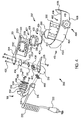
- FIG 4 is a detailed illustration of an exploded view of one embodiment of the communication device 200 and an adjustable headband 412.
- the adjustable headband 412 includes adjustment straps 412A and 412B, a ratchet sleeve 409 having an adjustment knob 410, a back 404, a front 405, a top edge 406, and a bottom edge 408.
- the headband 412 is adjusted by rotating the adjustment knob 410 on the ratchet sleeve 409. Rotating the adjustment knob 410 in one direction decreases the size of headband 412 by tightening adjustment straps 412A, 412B. Rotating the adjustment knob 410 in the opposite direction increases the size of headband 412 by loosening the adjustment straps 412 A, 412B.
- the communication device 200 includes a support member 201 that has an aperture 430.
- the rubber pad 427 has a flange 428 to retain the rubber pad 427 and prevent the rubber pad 427 from passing completely through the aperture 430.
- a vibration sensing device 420 which includes an accelerometer 421 and two capacitors 422,is connected to three wires 424, and is enclosed in a shrink wrap protector 426.
- the vibration sensing device 420 is encased in the sensing element cavity 208.
- the other ends of the three wires 424 (not shown) are connected to the printed circuit board (PCB) 120.
- PCB printed circuit board
- the wires 424 are protected from the environment by back plate 302 and the electronics housing 210.
- the bone conduction microphone 207 is made up of the vibration sensing device 420 and electrical circuitry located on PCB 120. It should be obvious that with minor circuit changes two wires can be used to connect the vibration sensing device 420 to PCB 120.
- the upper flange 204 of the support member 201 is configured to carry the electronics housing 210.
- the electronics housing 210 is secured to the upper flange 204 using a plurality of screws 435. Any method of securing the electronics housing to the upper flange, such as with an adhesive, a snap-fitting, etc. is contemplated.
- a gasket 436 seals the electronics housing 210 and protects the electronics from moisture and dirt.
- PCB 120 is located inside the electronics housing 210.
- a speaker assembly 108 is attached to the distal end of flexible boom 224.
- the proximal end of the flexible boom 224 is attached to the electronics housing 210.
- Electronics housing 210 has a first aperture (not shown) configured to receive the flexible boom 224.
- the proximal end of the flexible boom 224 is inserted through an O-ring 440 and through the first aperture where it is secured to electronics housing 210 with a snap-ring 438.
- the 0-ring 440 seals the connection between the flexible boom 224 and the electronics housing 210 and prevents dirt and moisture from entering the electronics housing 210.
- the speaker assembly 108 includes a speaker 450, gaskets 454, a speaker membrane 456 and a speaker cover 458, secured together by screws 435.
- the speaker 450 is connected to two wires 452, which are routed through the flexible boom 224 and connected to PCB 120. Electrical signals can be communicated to the speaker from PCB 120 causing the speaker membrane to vibrate and produce audible tones.
- the electronics housing 210 has a second aperture (now shown) configured to receive strain relief connector 218. Strain relief connector 218 is connected to radio interface cable 220. An O-ring 440 is inserted over strain relief connector 218 to prevent moisture and dirt from entering the electronics housing 210. The strain relief connector 218 is inserted through the second aperture and secured in the electronics housing by a snap ring 437. The wires in the radio interface cable 220 are connected to the printed circuit board. Radio interface cable 220 has a cable connector 222 configured to selectively connect to a hand-held radio transmitter/receiver and place the bone conduction microphone 207 and speaker 108 in circuit communication with the transmitter/receiver. The connection to the hand-held radio transmitter/receiver can be a direct connection or connected via the auxiliary microphone 130 ( Figure 1 ).
- the communication device 200 is configured to be easily added to or removed from a protective helmet 150.
- the communication device 200 is reversible i.e. it is configured so that a user can secure the communication device 200 to the protective helmet 150 such that the speaker assembly 108 can be placed on either the right or the left side of the protective helmet 150.
- the electronics housing is shaped and positioned to the side of the microphone in such a way that device can be mounted on the ratchet sleeve in two different configurations. The first configuration has the electronics housing and speaker on the user's left side, the second configuration having the electronics housing and speaker on the user's right side.
- the device is adapted for mounting in the first configuration by slipping the device over the top edge of the ratchet sleeve 409 and is adapted for mounting in the other configuration by slipping the device over the bottom edge of the ratchet sleeve 409.
- the speaker assembly can be positioned on the left side of the protective helmet 150 by positioning the communication device 200 over the ratchet sleeve 409 so that the microphone 207 is in front of ratchet sleeve 409 and the electronics housing 210 is in the back of ratchet sleeve 409.
- the communication device 200 is slipped over the top edge of the ratchet sleeve 409 and positioned so that the upper flange 204 comes to rest on the top edge 406 of ratchet sleeve 409 with the microphone 207 in front of ratchet sleeve 409 and the electronics housing 210 in back of ratchet sleeve 409.
- the lower flange 206 is positioned so that the lower flange 206 is directly below the bottom edge 408 of ratchet sleeve 409.
- tabs 212A, 212B are provided on the lower flange 206
- tabs 212C and 212D are provided on the upper flange 204.
- the tabs 212 A-D can be positioned behind the back 404 of ratchet sleeve 409.
- tabs 212 A-D can engage the back of the ratchet sleeve 409 and aid in securing the assembly 200 to the ratchet sleeve 409.
- the weight of the communication device 200 is carried by the upper flange 204.
- the speaker assembly can be positioned on the right side of the protective helmet 150 by positioning the communication device 200 upside down and below ratchet sleeve 409 so that the microphone 207 is in front of ratchet sleeve 409, and the electronics housing 210 is in back of ratchet sleeve 409.
- the communication device 200 is slipped over the bottom edge 408 of the ratchet sleeve 409 so that the upper flange 204 comes to rest on the bottom edge 408 of ratchet sleeve 409 with the microphone 207 in front of ratchet sleeve 409 and the electronic housing 210 in back of ratchet sleeve 409.
- the lower flange 206 is positioned so that the lower flange 206 is directly above the top edge 406 of ratchet sleeve 409 and tabs 212A and 212B, on the lower flange 206, and tabs 212C and 212D on the upper flange 204 are behind the back 404 of the ratchet sleeve 409.
- the tabs 212 A-D engage the back of the ratchet sleeve 409 and aid in securing the assembly 200 to the ratchet sleeve 409. In this configuration, the weight of the communications device 200 is carried by the lower flange 206.
- Bone conduction microphones must be positioned firmly against the bone through which the vibrations are traveling for the bone conduction microphone to consistently and reliably detect the vibrations and convert the detected vibrations to electrical signals.
- the bone conduction microphone described herein is capable of sensing vibrations from the cranium through intermediate materials, such as human hair, hoods, mask harnesses, protective liners, etc.
- the positioning of the bone conduction microphone 207 directly between the headband 412 and a user's head 307 greatly enhances the reliability and consistency of the communications. Further an optimal position for detecting the vibrations created by a user's vocal cords is in the center of the back of the user's head.
- Positioning a bone conduction microphone between a napestrap and the center of a user's head provides for reliable and consistent positioning of the bone microphone in an optimum position to detect the vibrations.
- the headband can be adjusted so that the pressure can be increased or decreased on the bone conduction microphone to firmly position it against the bone.
- the bone conduction microphone 207 can be located anywhere along the headband so that it is positioned between the headband and the user's head during use. Tightening the headband 412 directly increases contact pressure between the microphone and the cranial bones, which enables the vibrations to pass through the cranial bones and sensing element cavity with less loss of the vibrations. Thus, the vibrations are stronger and easier to detect by the vibration sensing device 402, which increases the reliability of the communications device.
- a headband having a ratchet sleeve is used and the contact pressure on the bone conduction microphone can be adjusted with a simple twist of an adjustment knob. As a result, adjustments can be made quickly and easily even in inconvenient circumstances, such as while fighting fires, or performing rescue operations.
Abstract
Description
- The present invention relates to a helmet having a communication device.
- Bone conduction microphones are known in the art and are used in communication systems for the transmission of speech. When a person speaks, the cranial bones vibrate in accordance with the sounds that are produced by the person's vocal cords. Bone conduction microphones detect vibrations in the user's cranial bones and convert the vibrations to electrical signals that can be communicated to a two-way radio. Bone conduction microphones are especially useful in noisy environments such as, for example, in helicopters, at fire stations, at construction sites, etc., where typical microphones may pick up and transmit a significant amount of ambient noise. Many of these environments require a user to wear a protective helmet that has an adjustable headband.
- Bone conduction microphones must firmly engage or abut the bone through which the vibrations are traveling for the bone conduction microphone to consistently and reliably detect the vibrations and convert the detected vibrations to electrical signals.
- Attempts have been made to attach bone conduction microphones to protective helmets. See for example
US-A-6 298 249 (the '249 patent) which discloses the precharacterising features of claim 1 and in which a bone conduction microphone is mounted on the napestrap of the helmet. The napestrap is the portion of the headband that is generally located in the rear of the helmet and is positioned over the nape of the neck. - These devices, however, include multiple movable parts that must be correctly adjusted for the bone conduction microphone to function properly. For example, the assembly of the '249 patent includes a sliding mechanism that must be closed around a ratchet sleeve, carried on the helmet's napestrap. A ratchet sleeve is a sleeve carried by the napestrap portion of the headband. The ratchet sleeve has an adjustable knob that rotates to increase/decrease the size of the headband. In addition, a screw mechanism must be tightened to secure the assembly to the ratchet sleeve. Further the microphone is on a separate adjustable flange and must be adjusted to fit the user's head, and a screw mechanism needs to be tightened to retain the microphone in its adjusted position.
- Moreover, these devices do not place the microphone in an optimal position to consistently and reliably detect the vibrations in the cranial bones. Further, the position of the microphone may need to be adjusted during use, which is impossible, or at least very inconvenient, in many circumstances, such as while fighting a fire, or in the middle of a rescue attempt. In addition, it is not easy and/or convenient to secure these devices to a helmet. Finally, these devices limit the placement of a speaker to one side of the helmet.
- According to the present invention, there is provided a helmet having a communication device, the device comprising:
- a bone conduction microphone; and
- a support to which the microphone is mounted and which is releasably mounted on a headband of the helmet, the headband comprising an adjustable ratchet sleeve configured for tightening and loosening the adjustable headband, characterised in that:
- the support is configured to releasably mount on the ratchet sleeve and position the microphone between the ratchet sleeve and the user's head, wherein tightening the headband increases pressure on the microphone and loosening the headband decreases pressure on the microphone, the pressure on the microphone being created by forces exerted between the headband and the user's head.
- Preferably, the headband comprises a napestrap having said ratchet sleeve. In this case, the support may be configured so that the device can be mounted on the ratchet sleeve in its use position without adjustment of moveable parts.
- The support may comprise an upper support flange for resting on the top edge of the ratchet sleeve so that the weight of the device is supported on the top edge of the ratchet sleeve while the ratchet sleeve simultaneously secures the microphone in direct engagement with the user's head in use of the device.
- The support may comprise: an upper support flange for resting on the top edge of the ratchet sleeve; and a lower support flange for positioning below the lower edge of the ratchet sleeve, the microphone, upper support flange and lower support flange together defining a U-shaped channel for receiving the ratchet sleeve. In this case, the support may be made from a single piece of molded plastic.
- The helmet could further comprise an electronics housing carried by the upper support flange of the support. In this case, the support may be configured to position the microphone at or near the center of the back of the user's head, the electronics housing being positioned to the side of the microphone. The electronics housing could be spaced rearwardly with respect to the microphone by a distance sufficient so that the ratchet sleeve can be slipped between the microphone and the electronics housing for mounting the device on the ratchet sleeve. In this case, the electronics housing could be shaped and positioned to the side of the microphone in such a way that the device can be mounted on the ratchet sleeve in two different configurations, a first configuration with the electronics housing on the user's left side, and a second configuration with the electronics housing on the user's right side, the device being adapted for mounting in one of these configurations by slipping the device over the top edge of the ratchet sleeve and being adapted for mounting in the other configuration by slipping the device over the lower edge of the ratchet sleeve.
- The helmet could further comprise a speaker for positioning near the ear of the user, and a flexible boom mounting the speaker to the electronics housing.
- The support may comprise an upper support flange for resting on the top edge of the ratchet sleeve so that the weight of the device is supported on the top edge of the ratchet sleeve, the ratchet sleeve being configured to place the microphone in direct engagement with the user's head while the device is in use. In this case, the support could further comprise a lower support flange, the upper support flange, the microphone and the lower support flange forming a generally U-shaped channel for receiving the ratchet sleeve. In this case, the support may be configured so that the device can be mounted on the ratchet sleeve in its use position without adjustment of moveable parts. The helmet could then further comprise a speaker, the speaker being supported by the upper support flange, and the speaker being spaced rearwardly with respect to the microphone by a distance sufficient so that the ratchet sleeve can be slipped between the microphone and the speaker. In this case, the helmet could further comprise a flexible boom, the flexible boom connecting the speaker to the upper support flange.
-
-
Figure 1A is a block diagram of one embodiment of a bone conduction microphone, radio transmitter/receiver, a speaker and an optional auxiliary microphone. -
Figure 1B is a perspective view of one embodiment of a protective helmet having an adjustable headband with a ratchet sleeve. -
Figure 1C is a perspective view one embodiment of of a ratchet sleeve located on the napestrap portion of an adjustable headband having a ratchet sleeve. -
Figure 2 is a perspective view of one embodiment of a communication device. -
Figure 3A is a plan view of the assembly illustrated inFigure 2 . -
Figure 3B is a front view of the assembly illustrated inFigure 2 . -
Figure 3C is a rear view of the assembly illustrated inFigure 2 . -
Figure 3D is a cross sectional view of the assembly illustrated inFigure 2 . -
Figure 4 is an exploded view of one embodiment of the inventive communications device with an adjustable napestrap. - Illustrated in
Figure 1 is an embodiment of acommunication system 100. Thecommunication system 100 includes a radio transmitter/receiver 102 electrically coupled to a printed circuit board (PCB) 120 viacable 110. PCB 120 is electrically coupled to abone conduction microphone 104 and aspeaker assembly 108 viacables bone conduction microphone 104 andspeaker 108 are placed in circuit communication with the radio transmitter/receiver 102. In addition, an optionalauxiliary microphone 130, such as a push-to-talk (PIT) microphone, a lapel microphone (LM),etc. is shown. As a result, PCB 120 can be placed directly in circuit communication with the radio transmitter/receiver, or placed in circuit communication with the radio transmitter/receiver 102 via theauxiliary microphone 130. - Vibrations in bones, such a cranial bones, are created when a user speaks. The
bone conduction microphone 104 detects and amplifies the vibrations in the cranial bones. Thebone conduction microphone 104 is made up of a vibration sensor (not shown) and electrical circuitry. The electrical circuitry can be located integral with the vibration sensor or remote from the vibration sensor. Preferably the electrical circuitry is located onPCB 120, or in circuitry located in the optional auxiliary microphone. The vibrations are detected and converted into electrical signals that are representative of the user's voice. The electrical signals can be communicated to the radio transmitter/receiver viacable 112 andPCB 120 where the electrical signals can be transmitted to a second radio receiver (not shown). One embodiment of a bone conduction microphone is disclosed inU.S. Pat. No. 5,054,079 . Other bone conduction microphones can also be used. - Electrical signals received by the radio transmitter/
receiver 102 can be communicated to thespeaker assembly 108 viacable 110,PCB 120 andcable 114. The electrical signals communicated to thespeaker assembly 108 cause a membrane (not shown) inside the speaker to vibrate. The vibrations in the membrane produce an aural transmission within the frequency range detectable by the user. Preferably, the aural transmissions are representative of a human voice. - The communication device, described herein, can be used with any helmet that has a headband. Preferably the helmet is a protective helmet, such as a fireman's helmet, a construction hardhat, etc.
Figure 1B illustrates a typicalprotective helmet 150. Theprotective helmet 150 includes ashell 152, asuspension harness 154, aheadband 170 having anapestrap portion 165, and aratchet sleeve 160. Theshell 152 provides protection from falling objects and is secured to the user's head by theheadband 170. Theheadband 170, which surrounds a user's head, is connected to theshell 152 via thesuspension harness 154. Generally theheadband 170 is adjustable. Theheadband 170 has afirst adjustment strap 170A and asecond adjustment strap 170B. Generally, the adjustment straps 170A, 170B are located in the back of thehelmet 150 and form part of thenapestrap 165. The portion of theheadband 170 engaging the lower rear portion of the user's head at or near the nape of the user's neck is referred to herein as thenapestrap 165. The adjustment straps 170A and 170B allow the size of theheadband 170 to be changed. Theheadband 170 may be adjusted in any known manner, such as with one or more projecting members or tabs (not shown) on adjustment strap 170a that can be inserted into a one or more holes (not shown), in a series of holes, onadjustment strap 170B, similar to the adjustment of a napestrap commonly used on baseball caps. The napestrap has a ratchet sleeve 160 (Figure 1C ), carried by thenapestrap 165 and described in more detail below, for easily adjusting the size of theheadband 170. - The
headband 170 for use with aratchet sleeve 160 has afirst adjustment strap 170A and asecond adjustment strap 170B. The adjustment straps 170A, 170B overlap inside of theratchet sleeve 160. Theratchet sleeve 160 has anadjustment knob 162 that rotates inside theratchet sleeve 160 and engages adjustment straps 170A and 170B. Rotating theadjustment knob 162 in one direction decreases the size of theheadband 170 by pullingadjustment straps ratchet sleeve 160. Rotating theadjustment knob 162 in the opposite direction increases the size of theheadband 170 by pushing the adjustment straps 170A and 170B out of theratchet sleeve 160. - Generally, headbands are made of relatively flexible rigid plastic material having a rectangular configuration. The rectangular configuration has a first dimension, typically between 1.91 cm and 2.54 cm (¾" and 1") and a second dimension, typically around 1.59 mm (1/16"). The rectangular configuration allows the
headband 170 to be rigid in one direction and be flexible in the other direction enabling it to roughly conform to the shape of the user's head. In addition, theratchet sleeve 160 is made of relatively rigid plastic that is curved slightly, roughly proportional to the curve of a typical user's head. Theratchet sleeve 160, while fairly rigid, also conforms to a user's head. While theheadband 170 is flexible in a first direction, it is rigid in the second direction. Thus the headband provides a desirable support for mounting a bone conduction microphone having the weight of the bone conduction microphone and its support carried by the headband. - Illustrated in
Figures 1 ,3A ,3B ,3C and3D is one embodiment of acommunication device 200. Thecommunication device 200 includes asupport member 201, abone conduction microphone 207, aspeaker assembly 108 connected to thesupport member 201 via aflexible boom 224, and acable 220 for placing thecommunication device 200 in circuit communication with a radio transmitter/receiver (not shown). Theflexible boom 224 can be made up of any flexible material, such a flexible conduit, rubber, multiconductor wire, etc. Preferably, however, theflexible boom 224 is hollow member to facilitate the passage of the electrical conductors required for the speaker. - The
support member 201 is used to releasably mount thebone conduction microphone 207 to theheadband 170 of the helmet. In one embodiment, thesupport member 201 includes asupport plate 202, anupper flange 204, alower flange 206, a plurality oftabs 212, and anelectronics housing 210. Theupper support flange 204 andlower flange 206 are attached to opposite sides of thesupport plate 202. In an alternative embodiment, thesupport flanges microphone 207 and thesupport plate 202 is not required. The support flanges 204 and 206 are substantially perpendicular to thesupport plate 202 forming a generally U-shaped channel. The U-shaped channel is curved slightly to conform to the general shape of thenapestrap 165 and/or ratchetsleeve 160. The upper and lower flanges 204,206, respectively, are configured to extend over a top edge and a bottom edge of napestrap 165 (Figures 3D and4 ) to facilitate securing the communication device to thenapestrap 165. Thus, thenapestrap 165 supports the weight of thecommunication device 200 when thecommunication device 200 is mounted on thenapestrap 165. In addition, thesupport member 201 positions themicrophone 207 between thenapestrap 165 and the user'shead 307. Securing thecommunication device 200 to thenapestrap 165 will be described in more detail below. Preferably thesupport plate 202 and support flanges 204,206 are curved slightly to conform to the general shape of anapestrap 165 in aprotective helmet 150. In addition, thelower flange 206 andupper flange 204 have a plurality oftabs support plate 202 so that thetabs 212 A-D extend perpendicular to thelower flange 206 andupper flange 204. When mounted on thenapestrap 165, thetabs 212 A-D extend upwardly from thelower flange 206 and downwardly from theupper flange 204 in the back of thenapestrap 165 and aid in the securing thesupport member 201 to thenapestrap 165. - The
upper flange 204 is configured to carry theelectronics housing 210. In one embodiment, theupper flange 204 extends beyond the end of thesupport plate 202, in the direction ofspeaker 108 and carries or supports theelectronics housing 210. Preferablyelectronics housing 210 has aface plate 214 that extends from theupper flange 204 to approximately the bottom ofsupport plate 202. Theface plate 214 is substantially parallel to the support plate 202 (seeFigure 2 ). It should be noted that since thesupport plate 202 is slightly curved, theface plate 214 is not literally parallel to thesupport plate 202. Preferably, theelectronics housing 210 is spaced rearwardly with respect to themicrophone 207 by a distance sufficient so that thenapestrap 165 can be slipped between themicrophone 207 and theelectronics housing 210. Preferably, theelectronics housing 210 is configured to receive aradio interface cable 220 and aflexible boom 224. Theradio interface cable 220 has acable connector 222 for connection to a radio transmitter/receiver (not shown) on a first end and a cablestrain relief connector 218 located near the second end. The cablestrain relief connector 218 is secured to theelectronics housing 210. - The
radio interface cable 220 is electrically coupled toPCB 120, which is located inelectronics housing 210. Preferably,PCB 120 is also coupled to thespeaker assembly 108 through wires (not shown) that are housed in theflexible boom 224. In one embodiment, thebone conduction microphone 207 is made up of a vibration sensing device 420 (Figure 4 ) that is encased in asensing element cavity 208, and electrical circuitry located onPCB 120. Thesensing element cavity 208 provides a soft surface for contacting a user'shead 307. The soft surface provides comfort during long periods of use. In addition, thesensing element cavity 208 provides a medium for conducting the vibrations traveling through the cranial bones to thevibration sensing device 420. In one embodiment, thesensing element cavity 208 is secured to the front of thesupport plate 202. Preferably, however, thesupport plate 202 has an aperture through it and thesensing element cavity 208 is inserted therethrough. In this embodiment, a back cover 302 (Figure 3C ) is utilized to secure thesensing element cavity 208 in place and to protect the wiring that extends out of the back of thesensing element cavity 208. Additionally, thesensing element cavity 208 can be protected by a rubber pad, wherein the rubber pad is configured to contact the user'shead 307 and provide a layer of protection for thesensing element cavity 208. s - In general, the U-shaped
channel support member 201 and theelectronics housing 210 form an aperture to receiveheadband 170,napestrap 165, and/or ratchet sleeve 160 (Fig. 1B ) therethrough. The weight of thecommunication device 200, theupper flange 204, and theelectronics housing 210 service to releasably mount thecommunication device 200 to thenapestrap 165. In addition, thetabs 212 A-D located on thelower flange 206 andupper flange 204 extend upwardly and downwardly, respectively, in the back of thenapestrap 165, and function to aid in releasably mounting the device to thenapestrap 165. In addition, the pressure applied to thecommunication device 200 while in use, with themicrophone 207 positioned between a user'shead 307 and thenapestrap 165, further acts to securely hold thecommunication device 200 in place. Thebone conduction microphone 207 can be positioned in a plurality of locations so that during use thebone conduction microphone 207 is between thenapestrap 165 and the user'shead 307. Preferably, the device positions thebone conduction microphone 207 in the center of the back of the user'shead 307. - The positioning of the bone conduction microphone, as used herein, includes the entire bone conduction microphone and/or a portion thereof. For example, the statement "placing the bone conduction microphone between the napestrap and the user's head" includes placing merely the vibration sensing portion of the bone conduction microphone between the napestrap and the user's head. Thus, a portion of the bone conduction microphone can be located in the electronics housing. As a result, the napestrap can be positioned between the bone conduction microphone and the electronics housing, even if a portion of the bone conduction microphone is located in the electronics housing.
-
Figure 4 is a detailed illustration of an exploded view of one embodiment of thecommunication device 200 and an adjustable headband 412. The adjustable headband 412 includes adjustment straps 412A and 412B, aratchet sleeve 409 having anadjustment knob 410, a back 404, a front 405, a top edge 406, and abottom edge 408. The headband 412 is adjusted by rotating theadjustment knob 410 on theratchet sleeve 409. Rotating theadjustment knob 410 in one direction decreases the size of headband 412 by tighteningadjustment straps adjustment knob 410 in the opposite direction increases the size of headband 412 by loosening the adjustment straps 412 A, 412B. - The
communication device 200 includes asupport member 201 that has anaperture 430. A portion of arubber pad 427, configured to enclose thesensing element cavity 208, fits through theaperture 430. Preferably, therubber pad 427 has aflange 428 to retain therubber pad 427 and prevent therubber pad 427 from passing completely through theaperture 430. Avibration sensing device 420, which includes anaccelerometer 421 and twocapacitors 422,is connected to threewires 424, and is enclosed in ashrink wrap protector 426. Thevibration sensing device 420 is encased in thesensing element cavity 208. The other ends of the three wires 424 (not shown) are connected to the printed circuit board (PCB) 120. Thewires 424 are protected from the environment byback plate 302 and theelectronics housing 210. Thebone conduction microphone 207 is made up of thevibration sensing device 420 and electrical circuitry located onPCB 120. It should be obvious that with minor circuit changes two wires can be used to connect thevibration sensing device 420 toPCB 120. - The
upper flange 204 of thesupport member 201 is configured to carry theelectronics housing 210. Theelectronics housing 210 is secured to theupper flange 204 using a plurality ofscrews 435. Any method of securing the electronics housing to the upper flange, such as with an adhesive, a snap-fitting, etc. is contemplated. Agasket 436 seals theelectronics housing 210 and protects the electronics from moisture and dirt.PCB 120 is located inside theelectronics housing 210. - A
speaker assembly 108 is attached to the distal end offlexible boom 224. The proximal end of theflexible boom 224 is attached to theelectronics housing 210.Electronics housing 210 has a first aperture (not shown) configured to receive theflexible boom 224. The proximal end of theflexible boom 224 is inserted through an O-ring 440 and through the first aperture where it is secured toelectronics housing 210 with a snap-ring 438. The 0-ring 440 seals the connection between theflexible boom 224 and theelectronics housing 210 and prevents dirt and moisture from entering theelectronics housing 210. Thespeaker assembly 108 includes aspeaker 450,gaskets 454, aspeaker membrane 456 and aspeaker cover 458, secured together byscrews 435. Thespeaker 450 is connected to twowires 452, which are routed through theflexible boom 224 and connected toPCB 120. Electrical signals can be communicated to the speaker fromPCB 120 causing the speaker membrane to vibrate and produce audible tones. - The
electronics housing 210 has a second aperture (now shown) configured to receivestrain relief connector 218.Strain relief connector 218 is connected toradio interface cable 220. An O-ring 440 is inserted overstrain relief connector 218 to prevent moisture and dirt from entering theelectronics housing 210. Thestrain relief connector 218 is inserted through the second aperture and secured in the electronics housing by asnap ring 437. The wires in theradio interface cable 220 are connected to the printed circuit board.Radio interface cable 220 has acable connector 222 configured to selectively connect to a hand-held radio transmitter/receiver and place thebone conduction microphone 207 andspeaker 108 in circuit communication with the transmitter/receiver. The connection to the hand-held radio transmitter/receiver can be a direct connection or connected via the auxiliary microphone 130 (Figure 1 ). - The
communication device 200 is configured to be easily added to or removed from aprotective helmet 150. In addition, thecommunication device 200 is reversible i.e. it is configured so that a user can secure thecommunication device 200 to theprotective helmet 150 such that thespeaker assembly 108 can be placed on either the right or the left side of theprotective helmet 150. In one embodiment, the electronics housing is shaped and positioned to the side of the microphone in such a way that device can be mounted on the ratchet sleeve in two different configurations. The first configuration has the electronics housing and speaker on the user's left side, the second configuration having the electronics housing and speaker on the user's right side. The device is adapted for mounting in the first configuration by slipping the device over the top edge of theratchet sleeve 409 and is adapted for mounting in the other configuration by slipping the device over the bottom edge of theratchet sleeve 409. - The speaker assembly can be positioned on the left side of the
protective helmet 150 by positioning thecommunication device 200 over theratchet sleeve 409 so that themicrophone 207 is in front ofratchet sleeve 409 and theelectronics housing 210 is in the back ofratchet sleeve 409. Thecommunication device 200 is slipped over the top edge of theratchet sleeve 409 and positioned so that theupper flange 204 comes to rest on the top edge 406 ofratchet sleeve 409 with themicrophone 207 in front ofratchet sleeve 409 and theelectronics housing 210 in back ofratchet sleeve 409. Thelower flange 206 is positioned so that thelower flange 206 is directly below thebottom edge 408 ofratchet sleeve 409. Preferablytabs lower flange 206, andtabs upper flange 204. Thetabs 212 A-D can be positioned behind the back 404 ofratchet sleeve 409. Thus,tabs 212 A-D can engage the back of theratchet sleeve 409 and aid in securing theassembly 200 to theratchet sleeve 409. In this configuration, the weight of thecommunication device 200 is carried by theupper flange 204. - The speaker assembly can be positioned on the right side of the
protective helmet 150 by positioning thecommunication device 200 upside down and belowratchet sleeve 409 so that themicrophone 207 is in front ofratchet sleeve 409, and theelectronics housing 210 is in back ofratchet sleeve 409. Thecommunication device 200 is slipped over thebottom edge 408 of theratchet sleeve 409 so that theupper flange 204 comes to rest on thebottom edge 408 ofratchet sleeve 409 with themicrophone 207 in front ofratchet sleeve 409 and theelectronic housing 210 in back ofratchet sleeve 409. Thelower flange 206 is positioned so that thelower flange 206 is directly above the top edge 406 ofratchet sleeve 409 andtabs lower flange 206, andtabs upper flange 204 are behind the back 404 of theratchet sleeve 409. Thetabs 212 A-D engage the back of theratchet sleeve 409 and aid in securing theassembly 200 to theratchet sleeve 409. In this configuration, the weight of thecommunications device 200 is carried by thelower flange 206. - Bone conduction microphones must be positioned firmly against the bone through which the vibrations are traveling for the bone conduction microphone to consistently and reliably detect the vibrations and convert the detected vibrations to electrical signals. The bone conduction microphone described herein is capable of sensing vibrations from the cranium through intermediate materials, such as human hair, hoods, mask harnesses, protective liners, etc. The positioning of the
bone conduction microphone 207 directly between the headband 412 and a user'shead 307 greatly enhances the reliability and consistency of the communications. Further an optimal position for detecting the vibrations created by a user's vocal cords is in the center of the back of the user's head. Positioning a bone conduction microphone between a napestrap and the center of a user's head provides for reliable and consistent positioning of the bone microphone in an optimum position to detect the vibrations. The headband can be adjusted so that the pressure can be increased or decreased on the bone conduction microphone to firmly position it against the bone. - As noted earlier, the
bone conduction microphone 207 can be located anywhere along the headband so that it is positioned between the headband and the user's head during use. Tightening the headband 412 directly increases contact pressure between the microphone and the cranial bones, which enables the vibrations to pass through the cranial bones and sensing element cavity with less loss of the vibrations. Thus, the vibrations are stronger and easier to detect by the vibration sensing device 402, which increases the reliability of the communications device. A headband having a ratchet sleeve is used and the contact pressure on the bone conduction microphone can be adjusted with a simple twist of an adjustment knob. As a result, adjustments can be made quickly and easily even in inconvenient circumstances, such as while fighting fires, or performing rescue operations.
Claims (16)
- A helmet (150) having a communication device (200), the device comprising:a bone conduction microphone (207); anda support (201) to which the microphone is mounted and which is releasably mounted on a headband (412) of the helmet, the headband comprising an adjustable ratchet sleeve (409) configured for tightening and loosening the adjustable headband, characterised in that:the support (201) is configured to releasably mount on the ratchet sleeve (409) and position the microphone (207) between the ratchet sleeve and the user's head, wherein tightening the headband (412) increases pressure on the microphone and loosening the headband decreases pressure on the microphone, the pressure on the microphone being created by forces exerted between the headband and the user's head.
- A helmet (150) according to claim 1, wherein the headband (412) comprises a napestrap (165) having said ratchet sleeve (409).
- A helmet (150) according to claim 2, wherein the support (201) is configured so that the device can be mounted on the ratchet sleeve (409) in its use position without adjustment of moveable parts.
- A helmet (150) according to claim 2 or 3, wherein the support (201) comprises an upper support flange (204) for resting on the top edge of the ratchet sleeve (409) so that the weight of the device is supported on the top edge of the ratchet sleeve while the ratchet sleeve simultaneously secures the microphone (207) in direct engagement with the user's head in use of the device.
- A helmet (150) according to claim 2 or 3, wherein the support (201) comprises: an upper support flange (204) for resting on the top edge of the ratchet sleeve (409); and a lower support flange (206) for positioning below the lower edge of the ratchet sleeve, the microphone (207), upper support flange and lower support flange together defining a U-shaped channel for receiving the ratchet sleeve.
- A helmet (150) according to claim 5, wherein the support (201) is made from a single piece of molded plastic.
- A helmet (150) according to any of claims 4 to 6, further comprising an electronics housing (210) carried by the upper support flange (204) of the support (201).
- A helmet (150) according to claim 7, wherein the support (201) is configured to position the microphone (207) at or near the center of the back of the user's head and further wherein the electronics housing (210) is positioned to the side of the microphone.
- A helmet (150) according to claim 8, wherein the electronics housing (210) is spaced rearwardly with respect to the microphone (207) by a distance sufficient so that the ratchet sleeve (409) can be slipped between the microphone and the electronics housing for mounting the device on the ratchet sleeve.
- A helmet (150) according to claim 9, wherein the electronics housing (210) is shaped and positioned to the side of the microphone (207) in such a way that the device can be mounted on the ratchet sleeve (409) in two different configurations, a first configuration with the electronics housing on the user's left side, and a second configuration with the electronics housing on the user's right side, the device being adapted for mounting in one of these configurations by slipping the device over the top edge of the ratchet sleeve and being adapted for mounting in the other configuration by slipping the device over the lower edge of the ratchet sleeve.
- A helmet (150) according to any of claims 7 to 10, further comprising a speaker (108) for positioning near the ear of the user, and a flexible boom (224) mounting the speaker to the electronics housing (210).
- A helmet (150) according to claim 1, wherein the support (201) comprises an upper support flange (204) for resting on the top edge of the ratchet sleeve (409) so that the weight of the device is supported on the top edge of the ratchet sleeve, wherein the ratchet sleeve is configured to place the microphone (207) in direct engagement with the user's head while the device is in use.
- A helmet (150) according to claim 12, wherein the support (201) further comprises a lower support flange (206), wherein the upper support flange (204), the microphone and the lower support flange form a generally U-shaped channel for receiving the ratchet sleeve (409).
- A helmet (150) according to claim 13, wherein the support (201) is configured so that the device can be mounted on the ratchet sleeve (409) in its use position without adjustment of moveable parts.
- A helmet (150) according to claim 14, further comprising a speaker (108), wherein the speaker is supported by the upper support flange (204), and the speaker is spaced rearwardly with respect to the microphone (207) by a distance sufficient so that the ratchet sleeve (409) can be slipped between the microphone and the speaker.
- A helmet (150) according to claim 15, further comprising a flexible boom (224), wherein the flexible boom connects the speaker (108) to the upper support flange (204).
Applications Claiming Priority (2)
| Application Number | Priority Date | Filing Date | Title |
|---|---|---|---|
| US10/609,829 US7110743B2 (en) | 2003-06-30 | 2003-06-30 | Communications device for a protective helmet |
| PCT/US2004/020337 WO2005004655A1 (en) | 2003-06-30 | 2004-06-25 | Communications device for a protective helmet |
Publications (2)
| Publication Number | Publication Date |
|---|---|
| EP1641361A1 EP1641361A1 (en) | 2006-04-05 |
| EP1641361B1 true EP1641361B1 (en) | 2008-04-23 |
Family
ID=33540936
Family Applications (1)
| Application Number | Title | Priority Date | Filing Date |
|---|---|---|---|
| EP04777047A Active EP1641361B1 (en) | 2003-06-30 | 2004-06-25 | Communications device for a protective helmet |
Country Status (8)
| Country | Link |
|---|---|
| US (1) | US7110743B2 (en) |
| EP (1) | EP1641361B1 (en) |
| CN (1) | CN100502711C (en) |
| AT (1) | ATE392825T1 (en) |
| AU (1) | AU2004255185B2 (en) |
| BR (1) | BRPI0410883A (en) |
| DE (1) | DE602004013317T2 (en) |
| WO (1) | WO2005004655A1 (en) |
Families Citing this family (49)
| Publication number | Priority date | Publication date | Assignee | Title |
|---|---|---|---|---|
| US20030224838A1 (en) * | 2001-07-18 | 2003-12-04 | Greg Skillicorn | Mask communication system |
| US7457427B2 (en) * | 2003-09-22 | 2008-11-25 | Ultra Electronics Audiopack, Inc. | Dual microphone assembly for mask |
| US20050201548A1 (en) * | 2004-03-12 | 2005-09-15 | Joseph Birli | Telephone interface for mask |
| US7394905B2 (en) | 2004-03-26 | 2008-07-01 | Ultra Electronics Audiopack, Inc. | Voice amplifier for mask |
| US20060177084A1 (en) * | 2004-07-29 | 2006-08-10 | Greg Skillicorn | Mask amplifier with separated elements |
| US8464362B2 (en) * | 2004-08-13 | 2013-06-18 | Mine Safety Appliances Company | Protective helmets and method of manufacture thereof |
| US7349551B2 (en) * | 2004-09-03 | 2008-03-25 | Ultra Electronics Audiopack, Inc. | Lapel microphone with push to talk switch |
| KR101215944B1 (en) * | 2004-09-07 | 2012-12-27 | 센시어 피티와이 엘티디 | Hearing protector and Method for sound enhancement |
| FR2890291B1 (en) * | 2005-09-07 | 2007-11-02 | Franck Dominique Pasc Przysiek | DEVICE FOR APPLYING A DEVICE COMMUNICATING WITH OSTEOPHONIA IN EQUIPMENT HAVING A LIVING BEAM. |
| WO2007095266A2 (en) * | 2006-02-10 | 2007-08-23 | Ultra Electronic Audiopack, Inc. | Communication system for heads-up display |
| US7963426B2 (en) * | 2006-03-10 | 2011-06-21 | Vetronix AG | Receptacle which can be fixed to a head covering and is intended for attachments for sighting devices |
| US7592911B1 (en) | 2006-12-12 | 2009-09-22 | Accu-Spatial Llc | Construction hard hat having electronic circuitry |
| FR2916609B1 (en) * | 2007-05-31 | 2010-10-08 | Newsteo | ELECTROMECHANICAL DEVICE FOR THE SOUNDING OF EXISTING PROTECTION EQUIPMENT |
| US20080304680A1 (en) * | 2007-06-01 | 2008-12-11 | Clinton Wilcox | Sound Generating Device |
| US20090022351A1 (en) * | 2007-07-20 | 2009-01-22 | Wieland Chris M | Tooth-magnet microphone for high noise environments |
| US8296868B2 (en) | 2007-08-17 | 2012-10-30 | Easton Sports, Inc. | Adjustable hockey helmet |
| US20090052714A1 (en) * | 2007-08-21 | 2009-02-26 | Ultra Electronics Audiopack, Inc. | High noise immunity emergency resonder communication system |
| SI2207444T1 (en) * | 2007-10-10 | 2013-03-29 | 3M Innovative Properties Company | Pivoting headgear system |
| US20100075619A1 (en) * | 2007-11-16 | 2010-03-25 | Jordan Lowell Solla | Hard hat with radio frequency communication |
| KR20110009678A (en) | 2008-04-22 | 2011-01-28 | 카르도 시스템즈, 인코퍼레이티드. | Neckpad communications system for a helmet |
| CN101834916A (en) * | 2009-03-13 | 2010-09-15 | 胡强 | Head-mounted voice transceiver |
| US8503711B2 (en) * | 2010-05-20 | 2013-08-06 | Michael Flynn | Hat mounted music system |
| WO2012100053A1 (en) * | 2011-01-19 | 2012-07-26 | X2Impact, Inc. | Headgear position and impact sensor |
| US8813270B2 (en) * | 2011-07-26 | 2014-08-26 | Vladimiro Pizzi | Helmet with flush aligned shield when closed |
| US9345282B2 (en) | 2011-07-27 | 2016-05-24 | Bauer Hockey, Inc. | Adjustable helmet for a hockey or lacrosse player |
| WO2013057745A1 (en) * | 2011-10-18 | 2013-04-25 | Brooklin S.R.L. | Multifunction protective helmet |
| CN103246256A (en) * | 2013-04-10 | 2013-08-14 | 合肥工业大学 | Field production safety monitoring system for building construction and application method thereof |
| US10455336B2 (en) * | 2013-10-11 | 2019-10-22 | Cochlear Limited | Devices for enhancing transmissions of stimuli in auditory prostheses |
| US10986454B2 (en) | 2014-01-06 | 2021-04-20 | Alpine Electronics of Silicon Valley, Inc. | Sound normalization and frequency remapping using haptic feedback |
| US8767996B1 (en) | 2014-01-06 | 2014-07-01 | Alpine Electronics of Silicon Valley, Inc. | Methods and devices for reproducing audio signals with a haptic apparatus on acoustic headphones |
| US8977376B1 (en) | 2014-01-06 | 2015-03-10 | Alpine Electronics of Silicon Valley, Inc. | Reproducing audio signals with a haptic apparatus on acoustic headphones and their calibration and measurement |
| US9560459B2 (en) | 2014-05-16 | 2017-01-31 | D. Wheatley Enterprises, Inc. | Modular voice amplification system for protective mask |
| US9642574B2 (en) * | 2014-10-17 | 2017-05-09 | Guardhat, Inc. | Biometric sensors assembly for a hard hat |
| US10383384B2 (en) * | 2014-10-17 | 2019-08-20 | Guardhat, Inc. | Electrical connection for suspension band attachment slot of a hard hat |
| DE102015006111A1 (en) * | 2015-05-11 | 2016-11-17 | Pfanner Schutzbekleidung Gmbh | helmet |
| CN104799474B (en) * | 2015-05-13 | 2017-10-31 | 郑州捷利工业设备有限公司 | Fireman's intelligence combat helmet |
| CN105011455B (en) * | 2015-07-29 | 2018-07-31 | 广东远峰电子科技股份有限公司 | A kind of helmet of riding of the changeable sounding guidance mode based on bone conduction earphone |
| US10051360B2 (en) * | 2016-02-18 | 2018-08-14 | Ron Abbott | Audio component assembly for aviation helmets and the like |
| CN105996273A (en) * | 2016-05-13 | 2016-10-12 | 陈昊 | Helmet provided with multifunctional head strap |
| US9910636B1 (en) * | 2016-06-10 | 2018-03-06 | Jeremy M. Chevalier | Voice activated audio controller |
| CN106877895A (en) * | 2017-03-28 | 2017-06-20 | 中山市宏星信息技术有限公司 | A kind of communication equipment |
| KR102529396B1 (en) * | 2018-05-18 | 2023-05-04 | 젠텍스코오포레이션 | Headsets and Headset Coupling Systems |
| CN110934598A (en) * | 2018-09-25 | 2020-03-31 | 深圳迈瑞生物医疗电子股份有限公司 | Blood oxygen probe |
| US10856599B1 (en) | 2019-03-12 | 2020-12-08 | Diego Cuenca | Hard hat with integrated electronic systems |
| US20210105074A1 (en) | 2019-10-02 | 2021-04-08 | NOTO Technologies Limited | Bone conduction communication system and method of operation |
| US11013289B1 (en) * | 2019-10-25 | 2021-05-25 | Raymond Lucero | Hard hat with an integral communication system |
| DE102021110198A1 (en) | 2020-04-30 | 2021-11-04 | Dräger Safety AG & Co. KGaA | Protective helmet with an adapter and method for detachable attachment of a module |
| USD964987S1 (en) * | 2020-06-17 | 2022-09-27 | Robert Bosch Gmbh | Electronic module for recording and transmitting |
| US11330374B1 (en) | 2020-10-21 | 2022-05-10 | JLI Electronics, Inc. | Head-gear mounted bone-conducting microphone |
Family Cites Families (41)
| Publication number | Priority date | Publication date | Assignee | Title |
|---|---|---|---|---|
| US2993962A (en) * | 1960-05-04 | 1961-07-25 | Forrest E Hothem | Combination of head-band and adjustable microphone cage |
| CH467591A (en) * | 1965-11-18 | 1969-01-31 | Tempelhof Ets | helmet |
| US3789427A (en) * | 1972-03-20 | 1974-02-05 | J Aileo | Headgear structure |
| US3787641A (en) * | 1972-06-05 | 1974-01-22 | Setcom Corp | Bone conduction microphone assembly |
| AT341009B (en) * | 1972-06-22 | 1978-01-10 | Int Standard Electric Corp | HOR SPRECH SET |
| US4023209A (en) * | 1975-12-17 | 1977-05-17 | Gentex Corporation | Protective helmet assembly with segmental outer shell |
| US4422185A (en) * | 1977-09-26 | 1983-12-27 | Cook Reuben E | Welding helmet |
| US4315335A (en) * | 1980-10-16 | 1982-02-16 | Kennedy Alvin B Jun | Dual safe helmet |
| EP0109646A1 (en) * | 1982-11-16 | 1984-05-30 | Pilot Man-Nen-Hitsu Kabushiki Kaisha | Pickup device for picking up vibration transmitted through bones |
| US5078130A (en) * | 1988-07-14 | 1992-01-07 | Gentex Corporation | Personnel headgear enabling free breathing of ambient air or selective breathing from various sources |
| JPH0755167B2 (en) | 1988-09-21 | 1995-06-14 | 松下電器産業株式会社 | Mobile |
| US4942628A (en) * | 1989-09-20 | 1990-07-24 | Mine Safety Appliances Company | Helmet suspension having ratchet adjustment |
| US5054079A (en) * | 1990-01-25 | 1991-10-01 | Stanton Magnetics, Inc. | Bone conduction microphone with mounting means |
| DE9003237U1 (en) | 1990-03-16 | 1990-05-23 | Holmberg Gmbh & Co Kg, 1000 Berlin, De | |
| US5404577A (en) | 1990-07-13 | 1995-04-04 | Cairns & Brother Inc. | Combination head-protective helmet & communications system |
| US5163093A (en) * | 1990-12-12 | 1992-11-10 | Stanton Magnetics, Inc. | Microphone mounting for a person's neck |
| EP0519621A1 (en) | 1991-06-03 | 1992-12-23 | Pioneer Electronic Corporation | Speech transmitter |
| DE4310793A1 (en) | 1993-04-02 | 1994-10-06 | Ceotronics Gmbh Elektronische | Structure-borne noise microphone for protective helmets or the like |
| US5678205A (en) * | 1994-12-21 | 1997-10-14 | Cairnsair, Inc. | Combination head-protective helmet and communications system |
| FR2729058B1 (en) | 1995-01-09 | 1997-03-14 | Gallet Sa | PROTECTIVE HELMET AND ITS CHAIN FIXING DEVICE |
| US5619754A (en) | 1995-02-13 | 1997-04-15 | Fibre-Metal Products, Co. | Protective cap with reversible headband |
| US5603117A (en) * | 1995-09-13 | 1997-02-18 | The United States Of America As Represented By The Secretary Of The Army | Protective helmet assembly |
| FI100848B (en) * | 1996-06-28 | 1998-03-13 | Kitek Oy Ab Insinoeoeritoimist | Speech garnish fastener in a helmet |
| JP2996389B2 (en) | 1996-07-03 | 1999-12-27 | 株式会社テムコジャパン | Simultaneous two-way communication device using ear microphone |
| FR2752165B1 (en) | 1996-08-12 | 1998-10-09 | Intertechnique Sa | RESPIRATORY PROTECTION EQUIPMENT WITH FAST SETUP |
| FI103249B (en) | 1996-08-16 | 1999-05-14 | Kitek Oy Ab Insinoeoeritoimist | Telephone for hearing protection |
| JPH1065996A (en) | 1996-08-23 | 1998-03-06 | Olympus Optical Co Ltd | Head wearable display device |
| US5950245A (en) | 1997-04-14 | 1999-09-14 | Mine Safety Appliances Company | Adjustable headband with a ratchet mechanism having different resistances |
| US5793878A (en) * | 1997-06-05 | 1998-08-11 | Chang; Ching-Wen | Headset microphone having a location apparatus |
| US5881160A (en) * | 1998-05-21 | 1999-03-09 | Sheppard; Stanley L. | Cap with audio system |
| US6178251B1 (en) | 1998-07-02 | 2001-01-23 | Labtec Corporation | Collar microphone |
| US6104816A (en) | 1998-08-31 | 2000-08-15 | The United States Of America As Represented By The Secretary Of The Navy | High noise communication system |
| US6298249B1 (en) * | 1998-10-08 | 2001-10-02 | Mine Safety Appliances Company | Radio apparatus head-protective helmet |
| JP3766221B2 (en) * | 1998-12-28 | 2006-04-12 | パイオニア株式会社 | Audio equipment |
| US6473651B1 (en) | 1999-03-02 | 2002-10-29 | Advanced Bionics Corporation | Fluid filled microphone balloon to be implanted in the middle ear |
| US6374407B1 (en) | 2000-05-31 | 2002-04-23 | Frank A. Howell | Counterweight-night vision goggle system |
| JP3525889B2 (en) * | 2000-11-28 | 2004-05-10 | 日本電気株式会社 | Notification method and processing system operated without being perceived by others around |
| USD460436S1 (en) * | 2001-01-31 | 2002-07-16 | Savox Solutions Oy Ab (Ltd) | Earphone or microphone |
| US6643378B2 (en) * | 2001-03-02 | 2003-11-04 | Daniel R. Schumaier | Bone conduction hearing aid |
| US6496589B1 (en) * | 2001-06-20 | 2002-12-17 | Telex Communications, Inc. | Headset with overmold |
| JP3532544B2 (en) | 2001-10-30 | 2004-05-31 | 株式会社テムコジャパン | Transmitter / receiver for mounting a face or cap strap |
-
2003
- 2003-06-30 US US10/609,829 patent/US7110743B2/en active Active
-
2004
- 2004-06-25 AU AU2004255185A patent/AU2004255185B2/en not_active Ceased
- 2004-06-25 BR BRPI0410883-3A patent/BRPI0410883A/en active Search and Examination
- 2004-06-25 DE DE602004013317T patent/DE602004013317T2/en active Active
- 2004-06-25 CN CNB2004800173804A patent/CN100502711C/en active Active
- 2004-06-25 AT AT04777047T patent/ATE392825T1/en not_active IP Right Cessation
- 2004-06-25 WO PCT/US2004/020337 patent/WO2005004655A1/en active Application Filing
- 2004-06-25 EP EP04777047A patent/EP1641361B1/en active Active
Also Published As
| Publication number | Publication date |
|---|---|
| US20040261158A1 (en) | 2004-12-30 |
| AU2004255185A1 (en) | 2005-01-20 |
| US7110743B2 (en) | 2006-09-19 |
| WO2005004655A1 (en) | 2005-01-20 |
| BRPI0410883A (en) | 2006-07-04 |
| ATE392825T1 (en) | 2008-05-15 |
| CN100502711C (en) | 2009-06-24 |
| AU2004255185B2 (en) | 2009-05-14 |
| DE602004013317T2 (en) | 2009-07-09 |
| EP1641361A1 (en) | 2006-04-05 |
| CN1809293A (en) | 2006-07-26 |
| DE602004013317D1 (en) | 2008-06-05 |
Similar Documents
| Publication | Publication Date | Title |
|---|---|---|
| EP1641361B1 (en) | Communications device for a protective helmet | |
| EP1551242B1 (en) | Communication apparatus and helmet | |
| CA1051352A (en) | Acoustical communications headset | |
| US6463157B1 (en) | Bone conduction speaker and microphone | |
| US4972468A (en) | Transceiver for hanging on an ear | |
| US5790681A (en) | Fixing assembly for a helmet headset | |
| CA2057206C (en) | Microphone mounting for a person's neck | |
| CA2308364A1 (en) | Headband for reversible mounting of headsets | |
| US20200413179A1 (en) | Earphones with a formable ear hook | |
| WO2007058281A1 (en) | Transmitter/receiver | |
| WO1998001008A1 (en) | Anti-eavesdropping device | |
| EP1186202B1 (en) | An underwater audio system | |
| DE69701959D1 (en) | IMPROVEMENT FOR ELECTRO-ACOUSTIC TRANSMISSION DEVICE FOR INSTALLATION IN A HELMET AND PROTECTIVE HELMET | |
| JPH11215581A (en) | Bone-conducting headset | |
| WO2002087282A1 (en) | Detachable helmet-mounted communications system | |
| AU2004202336B2 (en) | Speaker for a communication apparatus | |
| AU2004101069B4 (en) | Communication apparatus and helmet | |
| AU2003100285B4 (en) | Communication apparatus and helmet | |
| AU2003203807B2 (en) | Communication apparatus and helmet | |
| JP3068449U (en) | Helmet bone conduction transmitter / receiver | |
| AU2004202194A1 (en) | Microphone for a communication apparatus | |
| EP0904672A1 (en) | Anti-eavesdropping device | |
| WO2004030400A2 (en) | Apparatus for the reception of acoustic communication |
Legal Events
| Date | Code | Title | Description |
|---|---|---|---|
| PUAI | Public reference made under article 153(3) epc to a published international application that has entered the european phase |
Free format text: ORIGINAL CODE: 0009012 |
|
| 17P | Request for examination filed |
Effective date: 20060126 |
|
| AK | Designated contracting states |
Kind code of ref document: A1 Designated state(s): AT BE BG CH CY CZ DE DK EE ES FI FR GB GR HU IE IT LI LU MC NL PL PT RO SE SI SK TR |
|
| 17Q | First examination report despatched |
Effective date: 20060711 |
|
| DAX | Request for extension of the european patent (deleted) | ||
| 17Q | First examination report despatched |
Effective date: 20060711 |
|
| GRAP | Despatch of communication of intention to grant a patent |
Free format text: ORIGINAL CODE: EPIDOSNIGR1 |
|
| GRAS | Grant fee paid |
Free format text: ORIGINAL CODE: EPIDOSNIGR3 |
|
| GRAA | (expected) grant |
Free format text: ORIGINAL CODE: 0009210 |
|
| AK | Designated contracting states |
Kind code of ref document: B1 Designated state(s): AT BE BG CH CY CZ DE DK EE ES FI FR GB GR HU IE IT LI LU MC NL PL PT RO SE SI SK TR |
|
| REG | Reference to a national code |
Ref country code: GB Ref legal event code: FG4D |
|
| REG | Reference to a national code |
Ref country code: CH Ref legal event code: EP |
|
| REF | Corresponds to: |
Ref document number: 602004013317 Country of ref document: DE Date of ref document: 20080605 Kind code of ref document: P |
|
| REG | Reference to a national code |
Ref country code: IE Ref legal event code: FG4D Free format text: LANGUAGE OF EP DOCUMENT: FRENCH |
|
| PG25 | Lapsed in a contracting state [announced via postgrant information from national office to epo] |
Ref country code: SI Free format text: LAPSE BECAUSE OF FAILURE TO SUBMIT A TRANSLATION OF THE DESCRIPTION OR TO PAY THE FEE WITHIN THE PRESCRIBED TIME-LIMIT Effective date: 20080423 |
|
| NLV1 | Nl: lapsed or annulled due to failure to fulfill the requirements of art. 29p and 29m of the patents act | ||
| PG25 | Lapsed in a contracting state [announced via postgrant information from national office to epo] |
Ref country code: BG Free format text: LAPSE BECAUSE OF FAILURE TO SUBMIT A TRANSLATION OF THE DESCRIPTION OR TO PAY THE FEE WITHIN THE PRESCRIBED TIME-LIMIT Effective date: 20080723 Ref country code: ES Free format text: LAPSE BECAUSE OF FAILURE TO SUBMIT A TRANSLATION OF THE DESCRIPTION OR TO PAY THE FEE WITHIN THE PRESCRIBED TIME-LIMIT Effective date: 20080803 Ref country code: FI Free format text: LAPSE BECAUSE OF FAILURE TO SUBMIT A TRANSLATION OF THE DESCRIPTION OR TO PAY THE FEE WITHIN THE PRESCRIBED TIME-LIMIT Effective date: 20080423 Ref country code: PT Free format text: LAPSE BECAUSE OF FAILURE TO SUBMIT A TRANSLATION OF THE DESCRIPTION OR TO PAY THE FEE WITHIN THE PRESCRIBED TIME-LIMIT Effective date: 20080923 Ref country code: NL Free format text: LAPSE BECAUSE OF FAILURE TO SUBMIT A TRANSLATION OF THE DESCRIPTION OR TO PAY THE FEE WITHIN THE PRESCRIBED TIME-LIMIT Effective date: 20080423 |
|
| PG25 | Lapsed in a contracting state [announced via postgrant information from national office to epo] |
Ref country code: AT Free format text: LAPSE BECAUSE OF FAILURE TO SUBMIT A TRANSLATION OF THE DESCRIPTION OR TO PAY THE FEE WITHIN THE PRESCRIBED TIME-LIMIT Effective date: 20080423 Ref country code: PL Free format text: LAPSE BECAUSE OF FAILURE TO SUBMIT A TRANSLATION OF THE DESCRIPTION OR TO PAY THE FEE WITHIN THE PRESCRIBED TIME-LIMIT Effective date: 20080423 |
|
| ET | Fr: translation filed | ||
| PG25 | Lapsed in a contracting state [announced via postgrant information from national office to epo] |
Ref country code: SE Free format text: LAPSE BECAUSE OF FAILURE TO SUBMIT A TRANSLATION OF THE DESCRIPTION OR TO PAY THE FEE WITHIN THE PRESCRIBED TIME-LIMIT Effective date: 20080723 Ref country code: MC Free format text: LAPSE BECAUSE OF NON-PAYMENT OF DUE FEES Effective date: 20080630 Ref country code: DK Free format text: LAPSE BECAUSE OF FAILURE TO SUBMIT A TRANSLATION OF THE DESCRIPTION OR TO PAY THE FEE WITHIN THE PRESCRIBED TIME-LIMIT Effective date: 20080423 Ref country code: CZ Free format text: LAPSE BECAUSE OF FAILURE TO SUBMIT A TRANSLATION OF THE DESCRIPTION OR TO PAY THE FEE WITHIN THE PRESCRIBED TIME-LIMIT Effective date: 20080423 |
|
| REG | Reference to a national code |
Ref country code: CH Ref legal event code: PL |
|
| PG25 | Lapsed in a contracting state [announced via postgrant information from national office to epo] |
Ref country code: BE Free format text: LAPSE BECAUSE OF FAILURE TO SUBMIT A TRANSLATION OF THE DESCRIPTION OR TO PAY THE FEE WITHIN THE PRESCRIBED TIME-LIMIT Effective date: 20080423 Ref country code: RO Free format text: LAPSE BECAUSE OF FAILURE TO SUBMIT A TRANSLATION OF THE DESCRIPTION OR TO PAY THE FEE WITHIN THE PRESCRIBED TIME-LIMIT Effective date: 20080423 Ref country code: SK Free format text: LAPSE BECAUSE OF FAILURE TO SUBMIT A TRANSLATION OF THE DESCRIPTION OR TO PAY THE FEE WITHIN THE PRESCRIBED TIME-LIMIT Effective date: 20080423 |
|
| PLBE | No opposition filed within time limit |
Free format text: ORIGINAL CODE: 0009261 |
|
| STAA | Information on the status of an ep patent application or granted ep patent |
Free format text: STATUS: NO OPPOSITION FILED WITHIN TIME LIMIT |
|
| 26N | No opposition filed |
Effective date: 20090126 |
|
| REG | Reference to a national code |
Ref country code: IE Ref legal event code: MM4A |
|
| PG25 | Lapsed in a contracting state [announced via postgrant information from national office to epo] |
Ref country code: IE Free format text: LAPSE BECAUSE OF NON-PAYMENT OF DUE FEES Effective date: 20080625 Ref country code: EE Free format text: LAPSE BECAUSE OF FAILURE TO SUBMIT A TRANSLATION OF THE DESCRIPTION OR TO PAY THE FEE WITHIN THE PRESCRIBED TIME-LIMIT Effective date: 20080423 |
|
| PG25 | Lapsed in a contracting state [announced via postgrant information from national office to epo] |
Ref country code: CH Free format text: LAPSE BECAUSE OF NON-PAYMENT OF DUE FEES Effective date: 20080630 Ref country code: LI Free format text: LAPSE BECAUSE OF NON-PAYMENT OF DUE FEES Effective date: 20080630 |
|
| PG25 | Lapsed in a contracting state [announced via postgrant information from national office to epo] |
Ref country code: IT Free format text: LAPSE BECAUSE OF FAILURE TO SUBMIT A TRANSLATION OF THE DESCRIPTION OR TO PAY THE FEE WITHIN THE PRESCRIBED TIME-LIMIT Effective date: 20080423 |
|
| PG25 | Lapsed in a contracting state [announced via postgrant information from national office to epo] |
Ref country code: LU Free format text: LAPSE BECAUSE OF NON-PAYMENT OF DUE FEES Effective date: 20080625 Ref country code: HU Free format text: LAPSE BECAUSE OF FAILURE TO SUBMIT A TRANSLATION OF THE DESCRIPTION OR TO PAY THE FEE WITHIN THE PRESCRIBED TIME-LIMIT Effective date: 20081024 Ref country code: CY Free format text: LAPSE BECAUSE OF FAILURE TO SUBMIT A TRANSLATION OF THE DESCRIPTION OR TO PAY THE FEE WITHIN THE PRESCRIBED TIME-LIMIT Effective date: 20080423 |
|
| PG25 | Lapsed in a contracting state [announced via postgrant information from national office to epo] |
Ref country code: TR Free format text: LAPSE BECAUSE OF FAILURE TO SUBMIT A TRANSLATION OF THE DESCRIPTION OR TO PAY THE FEE WITHIN THE PRESCRIBED TIME-LIMIT Effective date: 20080423 |
|
| PG25 | Lapsed in a contracting state [announced via postgrant information from national office to epo] |
Ref country code: GR Free format text: LAPSE BECAUSE OF FAILURE TO SUBMIT A TRANSLATION OF THE DESCRIPTION OR TO PAY THE FEE WITHIN THE PRESCRIBED TIME-LIMIT Effective date: 20080724 |
|
| REG | Reference to a national code |
Ref country code: GB Ref legal event code: 732E Free format text: REGISTERED BETWEEN 20140619 AND 20140625 |
|
| REG | Reference to a national code |
Ref country code: DE Ref legal event code: R082 Ref document number: 602004013317 Country of ref document: DE Representative=s name: MAIKOWSKI & NINNEMANN PATENTANWAELTE, DE |
|
| REG | Reference to a national code |
Ref country code: DE Ref legal event code: R081 Ref document number: 602004013317 Country of ref document: DE Owner name: MSA TECHNOLOGY, LLC, CRANBERRY TOWNSHIP, US Free format text: FORMER OWNER: MINE SAFETY APPLIANCES COMP., LLC, CRANBERRY TOWNSHIP, PA., US Effective date: 20150223 Ref country code: DE Ref legal event code: R081 Ref document number: 602004013317 Country of ref document: DE Owner name: MSA TECHNOLOGY, LLC, CRANBERRY TOWNSHIP, US Free format text: FORMER OWNER: MINE SAFETY APPLIANCES CO., PITTSBURGH, PA., US Effective date: 20150126 Ref country code: DE Ref legal event code: R082 Ref document number: 602004013317 Country of ref document: DE Representative=s name: MAIKOWSKI & NINNEMANN PATENTANWAELTE, DE Effective date: 20150126 Ref country code: DE Ref legal event code: R082 Ref document number: 602004013317 Country of ref document: DE Representative=s name: MAIKOWSKI & NINNEMANN PATENTANWAELTE, DE Effective date: 20150223 Ref country code: DE Ref legal event code: R082 Ref document number: 602004013317 Country of ref document: DE Representative=s name: MAIKOWSKI & NINNEMANN PATENTANWAELTE PARTNERSC, DE Effective date: 20150223 Ref country code: DE Ref legal event code: R082 Ref document number: 602004013317 Country of ref document: DE Representative=s name: MAIKOWSKI & NINNEMANN PATENTANWAELTE PARTNERSC, DE Effective date: 20150126 |
|
| REG | Reference to a national code |
Ref country code: FR Ref legal event code: PLFP Year of fee payment: 13 |
|
| REG | Reference to a national code |
Ref country code: FR Ref legal event code: PLFP Year of fee payment: 14 |
|
| REG | Reference to a national code |
Ref country code: FR Ref legal event code: PLFP Year of fee payment: 15 |
|
| PGFP | Annual fee paid to national office [announced via postgrant information from national office to epo] |
Ref country code: GB Payment date: 20220506 Year of fee payment: 19 Ref country code: FR Payment date: 20220510 Year of fee payment: 19 Ref country code: DE Payment date: 20220505 Year of fee payment: 19 |
|
| REG | Reference to a national code |
Ref country code: DE Ref legal event code: R082 Ref document number: 602004013317 Country of ref document: DE Representative=s name: JONES DAY RECHTSANWAELTE PATENTANWAELTE, DE |
|
| P01 | Opt-out of the competence of the unified patent court (upc) registered |
Effective date: 20230626 |
|
| REG | Reference to a national code |
Ref country code: DE Ref legal event code: R119 Ref document number: 602004013317 Country of ref document: DE |
|
| GBPC | Gb: european patent ceased through non-payment of renewal fee |
Effective date: 20230625 |