EP1642644A1 - Apparatus for detecting target molecules - Google Patents
Apparatus for detecting target molecules Download PDFInfo
- Publication number
- EP1642644A1 EP1642644A1 EP05022337A EP05022337A EP1642644A1 EP 1642644 A1 EP1642644 A1 EP 1642644A1 EP 05022337 A EP05022337 A EP 05022337A EP 05022337 A EP05022337 A EP 05022337A EP 1642644 A1 EP1642644 A1 EP 1642644A1
- Authority
- EP
- European Patent Office
- Prior art keywords
- reaction vessel
- probe
- reaction
- detection
- array
- Prior art date
- Legal status (The legal status is an assumption and is not a legal conclusion. Google has not performed a legal analysis and makes no representation as to the accuracy of the status listed.)
- Granted
Links
Images


Classifications
-
- C—CHEMISTRY; METALLURGY
- C12—BIOCHEMISTRY; BEER; SPIRITS; WINE; VINEGAR; MICROBIOLOGY; ENZYMOLOGY; MUTATION OR GENETIC ENGINEERING
- C12Q—MEASURING OR TESTING PROCESSES INVOLVING ENZYMES, NUCLEIC ACIDS OR MICROORGANISMS; COMPOSITIONS OR TEST PAPERS THEREFOR; PROCESSES OF PREPARING SUCH COMPOSITIONS; CONDITION-RESPONSIVE CONTROL IN MICROBIOLOGICAL OR ENZYMOLOGICAL PROCESSES
- C12Q1/00—Measuring or testing processes involving enzymes, nucleic acids or microorganisms; Compositions therefor; Processes of preparing such compositions
- C12Q1/68—Measuring or testing processes involving enzymes, nucleic acids or microorganisms; Compositions therefor; Processes of preparing such compositions involving nucleic acids
- C12Q1/6813—Hybridisation assays
- C12Q1/6834—Enzymatic or biochemical coupling of nucleic acids to a solid phase
- C12Q1/6837—Enzymatic or biochemical coupling of nucleic acids to a solid phase using probe arrays or probe chips
-
- B—PERFORMING OPERATIONS; TRANSPORTING
- B01—PHYSICAL OR CHEMICAL PROCESSES OR APPARATUS IN GENERAL
- B01L—CHEMICAL OR PHYSICAL LABORATORY APPARATUS FOR GENERAL USE
- B01L3/00—Containers or dishes for laboratory use, e.g. laboratory glassware; Droppers
- B01L3/50—Containers for the purpose of retaining a material to be analysed, e.g. test tubes
- B01L3/508—Containers for the purpose of retaining a material to be analysed, e.g. test tubes rigid containers not provided for above
- B01L3/5082—Test tubes per se
-
- B—PERFORMING OPERATIONS; TRANSPORTING
- B01—PHYSICAL OR CHEMICAL PROCESSES OR APPARATUS IN GENERAL
- B01L—CHEMICAL OR PHYSICAL LABORATORY APPARATUS FOR GENERAL USE
- B01L7/00—Heating or cooling apparatus; Heat insulating devices
- B01L7/52—Heating or cooling apparatus; Heat insulating devices with provision for submitting samples to a predetermined sequence of different temperatures, e.g. for treating nucleic acid samples
-
- G—PHYSICS
- G01—MEASURING; TESTING
- G01N—INVESTIGATING OR ANALYSING MATERIALS BY DETERMINING THEIR CHEMICAL OR PHYSICAL PROPERTIES
- G01N21/00—Investigating or analysing materials by the use of optical means, i.e. using sub-millimetre waves, infrared, visible or ultraviolet light
- G01N21/17—Systems in which incident light is modified in accordance with the properties of the material investigated
- G01N21/25—Colour; Spectral properties, i.e. comparison of effect of material on the light at two or more different wavelengths or wavelength bands
- G01N21/251—Colorimeters; Construction thereof
- G01N21/253—Colorimeters; Construction thereof for batch operation, i.e. multisample apparatus
-
- G—PHYSICS
- G01—MEASURING; TESTING
- G01N—INVESTIGATING OR ANALYSING MATERIALS BY DETERMINING THEIR CHEMICAL OR PHYSICAL PROPERTIES
- G01N33/00—Investigating or analysing materials by specific methods not covered by groups G01N1/00 - G01N31/00
- G01N33/48—Biological material, e.g. blood, urine; Haemocytometers
- G01N33/50—Chemical analysis of biological material, e.g. blood, urine; Testing involving biospecific ligand binding methods; Immunological testing
- G01N33/53—Immunoassay; Biospecific binding assay; Materials therefor
- G01N33/543—Immunoassay; Biospecific binding assay; Materials therefor with an insoluble carrier for immobilising immunochemicals
- G01N33/54366—Apparatus specially adapted for solid-phase testing
-
- B—PERFORMING OPERATIONS; TRANSPORTING
- B01—PHYSICAL OR CHEMICAL PROCESSES OR APPARATUS IN GENERAL
- B01J—CHEMICAL OR PHYSICAL PROCESSES, e.g. CATALYSIS OR COLLOID CHEMISTRY; THEIR RELEVANT APPARATUS
- B01J2219/00—Chemical, physical or physico-chemical processes in general; Their relevant apparatus
- B01J2219/00274—Sequential or parallel reactions; Apparatus and devices for combinatorial chemistry or for making arrays; Chemical library technology
- B01J2219/00277—Apparatus
- B01J2219/00279—Features relating to reactor vessels
- B01J2219/00281—Individual reactor vessels
- B01J2219/00283—Reactor vessels with top opening
-
- B—PERFORMING OPERATIONS; TRANSPORTING
- B01—PHYSICAL OR CHEMICAL PROCESSES OR APPARATUS IN GENERAL
- B01J—CHEMICAL OR PHYSICAL PROCESSES, e.g. CATALYSIS OR COLLOID CHEMISTRY; THEIR RELEVANT APPARATUS
- B01J2219/00—Chemical, physical or physico-chemical processes in general; Their relevant apparatus
- B01J2219/00274—Sequential or parallel reactions; Apparatus and devices for combinatorial chemistry or for making arrays; Chemical library technology
- B01J2219/00277—Apparatus
- B01J2219/00497—Features relating to the solid phase supports
- B01J2219/00527—Sheets
- B01J2219/00529—DNA chips
-
- B—PERFORMING OPERATIONS; TRANSPORTING
- B01—PHYSICAL OR CHEMICAL PROCESSES OR APPARATUS IN GENERAL
- B01J—CHEMICAL OR PHYSICAL PROCESSES, e.g. CATALYSIS OR COLLOID CHEMISTRY; THEIR RELEVANT APPARATUS
- B01J2219/00—Chemical, physical or physico-chemical processes in general; Their relevant apparatus
- B01J2219/00274—Sequential or parallel reactions; Apparatus and devices for combinatorial chemistry or for making arrays; Chemical library technology
- B01J2219/00277—Apparatus
- B01J2219/0054—Means for coding or tagging the apparatus or the reagents
-
- B—PERFORMING OPERATIONS; TRANSPORTING
- B01—PHYSICAL OR CHEMICAL PROCESSES OR APPARATUS IN GENERAL
- B01J—CHEMICAL OR PHYSICAL PROCESSES, e.g. CATALYSIS OR COLLOID CHEMISTRY; THEIR RELEVANT APPARATUS
- B01J2219/00—Chemical, physical or physico-chemical processes in general; Their relevant apparatus
- B01J2219/00274—Sequential or parallel reactions; Apparatus and devices for combinatorial chemistry or for making arrays; Chemical library technology
- B01J2219/00583—Features relative to the processes being carried out
- B01J2219/00585—Parallel processes
-
- B—PERFORMING OPERATIONS; TRANSPORTING
- B01—PHYSICAL OR CHEMICAL PROCESSES OR APPARATUS IN GENERAL
- B01J—CHEMICAL OR PHYSICAL PROCESSES, e.g. CATALYSIS OR COLLOID CHEMISTRY; THEIR RELEVANT APPARATUS
- B01J2219/00—Chemical, physical or physico-chemical processes in general; Their relevant apparatus
- B01J2219/00274—Sequential or parallel reactions; Apparatus and devices for combinatorial chemistry or for making arrays; Chemical library technology
- B01J2219/00583—Features relative to the processes being carried out
- B01J2219/00596—Solid-phase processes
-
- B—PERFORMING OPERATIONS; TRANSPORTING
- B01—PHYSICAL OR CHEMICAL PROCESSES OR APPARATUS IN GENERAL
- B01J—CHEMICAL OR PHYSICAL PROCESSES, e.g. CATALYSIS OR COLLOID CHEMISTRY; THEIR RELEVANT APPARATUS
- B01J2219/00—Chemical, physical or physico-chemical processes in general; Their relevant apparatus
- B01J2219/00274—Sequential or parallel reactions; Apparatus and devices for combinatorial chemistry or for making arrays; Chemical library technology
- B01J2219/0068—Means for controlling the apparatus of the process
- B01J2219/00702—Processes involving means for analysing and characterising the products
- B01J2219/00707—Processes involving means for analysing and characterising the products separated from the reactor apparatus
-
- B—PERFORMING OPERATIONS; TRANSPORTING
- B01—PHYSICAL OR CHEMICAL PROCESSES OR APPARATUS IN GENERAL
- B01J—CHEMICAL OR PHYSICAL PROCESSES, e.g. CATALYSIS OR COLLOID CHEMISTRY; THEIR RELEVANT APPARATUS
- B01J2219/00—Chemical, physical or physico-chemical processes in general; Their relevant apparatus
- B01J2219/00274—Sequential or parallel reactions; Apparatus and devices for combinatorial chemistry or for making arrays; Chemical library technology
- B01J2219/00718—Type of compounds synthesised
- B01J2219/0072—Organic compounds
- B01J2219/00722—Nucleotides
-
- B—PERFORMING OPERATIONS; TRANSPORTING
- B01—PHYSICAL OR CHEMICAL PROCESSES OR APPARATUS IN GENERAL
- B01L—CHEMICAL OR PHYSICAL LABORATORY APPARATUS FOR GENERAL USE
- B01L2300/00—Additional constructional details
- B01L2300/06—Auxiliary integrated devices, integrated components
- B01L2300/0627—Sensor or part of a sensor is integrated
- B01L2300/0636—Integrated biosensor, microarrays
-
- B—PERFORMING OPERATIONS; TRANSPORTING
- B01—PHYSICAL OR CHEMICAL PROCESSES OR APPARATUS IN GENERAL
- B01L—CHEMICAL OR PHYSICAL LABORATORY APPARATUS FOR GENERAL USE
- B01L2300/00—Additional constructional details
- B01L2300/08—Geometry, shape and general structure
- B01L2300/0848—Specific forms of parts of containers
- B01L2300/0851—Bottom walls
-
- C—CHEMISTRY; METALLURGY
- C40—COMBINATORIAL TECHNOLOGY
- C40B—COMBINATORIAL CHEMISTRY; LIBRARIES, e.g. CHEMICAL LIBRARIES
- C40B40/00—Libraries per se, e.g. arrays, mixtures
- C40B40/04—Libraries containing only organic compounds
- C40B40/06—Libraries containing nucleotides or polynucleotides, or derivatives thereof
-
- C—CHEMISTRY; METALLURGY
- C40—COMBINATORIAL TECHNOLOGY
- C40B—COMBINATORIAL CHEMISTRY; LIBRARIES, e.g. CHEMICAL LIBRARIES
- C40B60/00—Apparatus specially adapted for use in combinatorial chemistry or with libraries
- C40B60/14—Apparatus specially adapted for use in combinatorial chemistry or with libraries for creating libraries
-
- C—CHEMISTRY; METALLURGY
- C40—COMBINATORIAL TECHNOLOGY
- C40B—COMBINATORIAL CHEMISTRY; LIBRARIES, e.g. CHEMICAL LIBRARIES
- C40B70/00—Tags or labels specially adapted for combinatorial chemistry or libraries, e.g. fluorescent tags or bar codes
Definitions
- the invention relates to a reaction vessel, an apparatus and a method for detecting specific interactions between molecular target and probe molecules.
- Biomedical tests are often based on the detection of an interaction between a molecule that is present in a known amount and position (the molecular probe) and an unknown molecule to be detected or unknown molecules to be detected (the molecular target or target molecules).
- the probes are stored in the form of a substance library on carriers, the so-called micro-arrays or chips, so that a sample can be analyzed simultaneously on several probes simultaneously (DJ Lockhart, EA Winzeler, Genomics, gene expression and DNA arrays; Nature 2000, 405, 827-836).
- the probes are usually immobilized in a predetermined manner on a suitable matrix, described for example in WO 00/12575 (see, for example, US Pat. No. 5,412,087, WO 98/36827) or produced synthetically (see, for example, US Pat. No. 5,143,854) ).
- the detection of an interaction between the probe and the target molecule is usually carried out as follows: After fixing the probe or the probes in a predetermined manner to a specific matrix in the form of a microarray, the targets are brought into contact with the probes in a solution and incubated under defined conditions. As a result of the incubation, a specific interaction takes place between the probe and the target. The binding involved is significantly more stable than the binding of target molecules to probes that are not specific for the target molecule. To remove target molecules that have not been specifically bound, the system is washed or heated with appropriate solutions.
- Detection of the specific interaction between a target and its probe can then be accomplished by a variety of methods, which typically depend on the type of marker that has been introduced into target molecules before, during or after the interaction of the target molecule with the microarray is.
- markers are fluorescent groups, so that specific target-probe interactions with high spatial resolution and compared to other conventional detection methods, especially mass-sensitive methods, can be read fluorescence optically with little effort (A. Marshall, J. Hodgson , DNA chips: An array ofpossibilities, Nature Biotechnology 1998, 16, 27-31; G. Ramsay, DNA Chips: State of the Art, Nature Biotechnology 1998, 16 "40-44).
- Substance libraries that can be immobilized on microarrays or chips include antibody libraries, receptor libraries, peptide libraries and nucleic acid libraries.
- the nucleic acid libraries are by far the most important. These are microarrays on which deoxyribonucleic acid (DNA) molecules or ribonucleic acid (RNA) molecules are immobilized.
- DNA deoxyribonucleic acid
- RNA ribonucleic acid
- a prerequisite for the binding of a target molecule, for example labeled with a fluorescence group, in the form of a DNA or RNA molecule to a nucleic acid probe of the microarray is that both the target molecule and the probe molecule are in the form of a single-stranded nucleic acid. Only between such molecules can an efficient and specific hybridization take place.
- Single-stranded nucleic acid target and nucleic acid probe molecules are generally obtained by heat denaturation and optimum choice of parameters such as temperature, ionic strength and concentration of helix destabilizing molecules. Thus, it is ensured that only probes with almost perfectly complementary, ie corresponding sequences remain paired with the target sequence (AA Leitch, T. Schwarzacher, D. Jackson, IJ Leitch, 1994, in vitro hybridization, Spektrum Akademischer Verlag, Heidelberg Berlin Oxford) ,
- a typical example of the use of microarrays in biological test methods is the detection of microorganisms in samples in biomedical diagnostics. It makes use of the fact that the ribosomal RNA (rRNA) genes are ubiquitously distributed and have sequences that are characteristic of each species. These species-characteristic sequences are applied to a microarray in the form of single-stranded DNA oligonucleotides.
- the target DNA molecules to be investigated are first isolated from the sample to be investigated and provided with markers, for example fluorescent markers. Subsequently, the labeled target DNA molecules are incubated in a solution with the probes applied to the microarray, non-specific interactions are removed by appropriate washing steps and specific interactions are detected by fluorescence optical evaluation. In this way, it is possible with a single test in a sample simultaneously z.
- micro-arrays or chips are fixed in closed chambers, which have inlets and outlets for changing the liquids required for the washing steps and hybridization steps.
- closed chambers Such systems are e.g. in US 6,287,850 and WO 01/02094.
- DE 199 40 750 describes a carrier for analyte determination method which, after slight design changes for use in array applications, is also suitable for this invention.
- Sequence analysis of DNA typically uses surface-bound DNA libraries mounted on slides. To carry out the Hybridization reaction on these slides so far special Hybridmaschineskammem or incubation chambers are used. In order to ensure the temperature and the mixing of the hybridization solution in these previously known chambers, a specially adapted for the device used and therefore consuming and expensive equipment is required.
- a flow cell which is suitable for performing a PCR and hybridization reactions on DNA chips.
- the flow cell described therein is a complex component, which is provided with a number of technical features that exclude the use of a commonly used in laboratories equipment such as a thermal mixer (Eppendorf, Germany, Hamburg) or a laboratory centrifuge (Heraeus, Hanau, Germany) ,
- WO 01/02094 describes a cartridge comprising a DNA chip. In this cartridge, both a PCR and a hybridization reaction can be performed on a DNA chip.
- WO 95/33846 describes a body with a depression into which a substrate with nucleic acid molecules of known sequence is incorporated on defined regions. The body has a closed cavity into which the sample liquid can be injected. The filling channels are sealed via septa and opened with suitable piercing cannulas to fill the body or the cartridge.
- the use of the cartridges described above also requires dedicated apparatus.
- US 5,856,174 describes a miniaturized integrated nucleic acid diagnostic device. This device allows the collection of one or more samples, their preparation and the subsequent performance of several sample analyzes. Such a device is used for automatically performing a DNA chip based analysis Combination and miniaturization of all steps on a cartridge. The provision of such a device is extremely complicated and expensive.
- No. 5,545,531 describes a method for the production of microtiter plates whose bottom is a wafer having a sample matrix at each site where there is a depression in the microtiter plate.
- US 5,874,219 a method for the competitive performance of biological tests is described, in which a plurality of reaction vessels are arranged contiguously next to one another and each vessel is provided with a molecular sample template.
- This biological chip reaction vessel plate is designed so that the interactions can be read on the molecular sample matrix with appropriate readers. In this way, a series of biological samples can be examined side by side and in parallel with molecular sample matrices. For carrying out individual tests, the reaction vessel plate described there is not suitable. The preparation of such a reaction vessel plate is described in US 5,545,531.
- WO 99/35499 a device is described in which substance libraries are addressably mounted on a disc similar to a modern compact disc (CD). By rotating the disc, a certain substance can be approached on the disc. The reading head of the reading device is then movable along the radius of the disc. The position of the disc can be determined by integrated tracks readable with a standard CD player. The interaction of the sample with a target substance can be done by absorption measurements and fluorescence measurements in transmitted or reflected light. Likewise, magnetic particles can be stored, which can be detected with a magnetic read head. In order to visualize the interaction reaction, staining by a silver precipitate is suggested in particular, whose deposition is mediated via a streptavidin / biotin-gold conjugate.
- WO 00/72018 discloses a method for silver deposition on microscope slides for visualizing interaction reactions of substance libraries. Furthermore, necessary reading devices are described.
- the present invention is therefore based on the object to provide an apparatus for performing array method, which is characterized by simple construction, easy handling and thus cost-effective production.
- Another object of the present invention is to provide a reaction vessel that can be used in such a device and is also characterized by easy handling and compatibility with commonly used in laboratories devices such as table centrifuges and pipettes.
- it is an object of the present invention to provide a reaction vessel that allows microarray-based assays to be performed in a single-chamber system while avoiding sources of contamination.
- a reaction vessel which has a shape and / or typical size typical for a laboratory reaction vessel and in which a support element with probe molecules immobilized thereon on predetermined regions is arranged on one of its base surfaces.
- reaction vessel according to the invention for the detection of specific interactions between molecular target and probe molecules offers the significant advantage that the acquisition of additional equipment or additional equipment for carrying out the detection reactions is not required, since usually in laboratories, especially in biological laboratories can be used for standard laboratory reaction vessels, such as table centrifuges and pipettes.
- Another advantage of the reaction vessel according to the invention is that a separate incubation chamber is superfluous, since the reaction vessel also serves as a hybridization chamber.
- the surface of the support with the probe molecules immobilized thereon is protected from contamination and other adverse external influences by the lid lock typical of conventional laboratory reaction vessels, such as the Safe-Lock lid lock on Eppendorf tubes.
- laboratory reaction vessels of a typical shape and size are understood to be reaction vessels which are usually used as disposable reaction vessels, in the standard version 1.5 ml, in laboratories, in particular biological or molecular biology.
- laboratory reaction vessels are also referred to as tubes and, according to the most important manufacturer, in particular as Eppendorf tubes or "Eppis” (Hamburg, Germany).
- Eppendorf tubes Eppis
- laboratory reaction vessels with a typical shape and size of Eppendorf are offered as standard reaction vessels or safe-lock reaction vessels.
- reaction vessels from manufacturers such as Greiner (Frickenhausen, Germany), Millipore (Eschborn, Germany), Heraeus (Hanau, Germany) and BIOplastics (Landgraaf, Netherlands) as well as other manufacturers can be used which have a shape and size as is typical for laboratory reaction vessels, in particular Eppendorf. Examples of laboratory reaction vessels with a typical shape and size are shown in Figure 21.
- the reaction vessel according to the invention differs from the above-mentioned reaction vessels in that a carrier element with probe molecules immobilized on predetermined regions is arranged on one of its base surfaces.
- a carrier element with probe molecules immobilized thereon on predetermined regions is also referred to below as a chip or affinity matrix.
- the predetermined areas on the carrier are also referred to below as array elements.
- the reaction vessel has a typical shape and / or size for a laboratory reaction vessel.
- the reaction vessel according to the invention thus has a rotationally symmetrical shape, in particular a cylindrical or substantially cylindrical shape.
- a conical shape deviating from the cylindrical basic shape is furthermore included, the taper preferably occurring in the direction of the affinity matrix.
- Typical shapes are also combinations of cylindrical or substantially cylindrical areas and conical areas (see, inter alia, Figures 1-4 and 21).
- the reaction vessel according to the invention is compatible in particular with conventional bench centrifuges, for example from manufacturers such as Eppendorf or Heraeus, ie the reaction vessel according to the invention is suitable for centrifugation in conventional bench centrifuges.
- Usual maximum outer diameter for standard laboratory reaction vessels and thus also for the reaction vessel according to the invention are in the range of 0.8 cm to 2 cm, preferably 1.0 cm to 1.5 cm and particularly preferably 1.1 cm to 1.3 cm. Further preferred outer diameters are up to 0.9 cm, up to 1.2 cm, up to 1.4 cm, up to 1.6 cm and up to 1.7 cm.
- the height of the reaction vessel according to the invention is usually 1.5 cm to 5.0 cm, preferably 2.0 cm to 4.0 cm, more preferably 2.5 cm to 3.5 cm, and most preferably 2.8 cm to 3 , 2 cm. Further preferred heights are to 2.6 cm, to 2.7 cm, to 2.9 cm, to 3.0 cm, to 3.1 cm, to 3.3 cm and to 3.4 cm. In specific embodiments, the height may also be 1.0 cm or more.
- the reaction vessel according to the invention can be centrifuged in conventional table centrifuges and can thus be used, for example, in conventional bench centrifuges such as a standard Eppendorf standard bench centrifuge as well as in conventional racks and holders for reaction vessels such as a tube rack from Eppendorf. Conventional pipettes or syringes such as Eppendorf variable volume and fixed volume pipettes may be used to introduce the sample to be examined and other reagents required to perform the detection reaction into the reaction vessel.
- the arrangement of the chip in the reaction vessel according to the invention allows the detection of the interaction reaction between target and probe molecules by conventional methods such as fluorescence detection or radiochemical methods. Be particularly advantageous, the application of absorption measurements has been found, as they are particularly inexpensive to perform. Such absorption measurement can be substantially improved and reduced by using a reactive dyeing method which takes place at the surface areas where an interaction reaction has occurred.
- a reactive dyeing method which takes place at the surface areas where an interaction reaction has occurred.
- the deposition of silver on target molecules labeled with gold nanospheres has proven useful (see DE 100 33 334.6 and WO 02/02810).
- a device may be used which uses one or more light emitting diodes of any emission wavelength as the light source and, for example, a CCD camera for spatially resolved detection of the interaction reaction on the predetermined areas of the chip.
- a probe array is understood to mean an arrangement of molecular probes on a surface, the position of each probe being determined separately.
- the array comprises defined locations or predetermined areas, so-called array elements, which are particularly preferably arranged in a specific pattern, wherein each array element usually contains only one species of probes.
- a probe or a probe molecule is understood as meaning a molecule which is used for the detection of other molecules by a specific, characteristic binding behavior or a specific reactivity.
- the probes arranged on the array can be any kind of molecules that can be coupled to solid surfaces and have a specific affinity. In a preferred embodiment, it is biopolymers from the classes of peptides, proteins, nucleic acids and / or their analogs.
- the probes are particularly preferably nucleic acids and / or nucleic acid analogs.
- nucleic acids both DNA and RNA molecules can be used.
- the oligonucleotide probes may be oligonucleotides of 10 to 100 bases in length, preferably 15 to 50 bases, and more preferably 20 to 30 bases in length, immobilized on the array surface.
- a target or a target molecule is understood to be the molecule to be detected by a molecular probe.
- the targets to be detected are nucleic acids.
- the probe array according to the invention can be used analogously for the detection of protein / probe interactions, antibody / probe interactions, etc.
- an array element or a predetermined region is understood to mean an area on a surface intended for the deposition of a molecular probe; the sum of all occupied array elements is the probe array.
- a marker in the context of the present invention denotes a detectable entity, for example a fluorophore or an anchor group, to which a detectable entity can be coupled.
- a substrate is understood as meaning a molecule or a combination of molecules dissolved in the reaction medium, which is deposited locally with the aid of a catalyst or a crystallization nucleus and / or a reacting agent.
- the reacting agent may be, for example, a reducing agent as in silver deposition or an oxidizing agent as in the production of a dye by enzymatic oxidation.
- a carrier element or carrier is understood to mean a solid body on which the probe array is constructed.
- the carrier element with the probes arranged thereon is also referred to below as a chip and, in specific embodiments of the present invention, may also comprise a basic element on which the actual chip is arranged.
- the carrier element can be arranged in the reaction vessel according to the invention by simply being inserted or clamped into a laboratory reaction vessel, preferably by the chip surface is designed such that it can be accurately inserted or clamped in a laboratory reaction vessel, for example in its lid.
- a base of the laboratory reaction vessel is flattened so that the support member can be mounted thereon. If there are technical reasons, then the carrier or the chip can also be installed in the side walls of the reaction vessel according to the invention.
- the base area preferably the bottom of the laboratory reaction vessel, has a recess for receiving the carrier.
- the carrier or chip for example, glued from the inside and / or from the outside and / or clamped and / or screwed and / or welded, in particular by laser welding, and / or snapped.
- the reaction vessel according to the invention has a typical for a laboratory reaction vessel shape and size and shaped as a border breakthrough for receiving the affinity matrices, in particular of surface-bound substance libraries. Examples of such embodiments of the reaction vessel according to the invention are given in Figures 1 to 4. In addition to the variants shown there are, of course, further combinations of the type of attachment of the carrier conceivable.
- the incorporation of the carrier or chip from the inside has the advantage that the carrier or chip is also at higher internal pressure, e.g. when used in a centrifuge or when heating the sample liquid to temperatures near the boiling point, in the reaction vessel can not be pushed out of its attachment to the outside.
- the installation requires more effort than the installation from the outside.
- Clamping or thread or grids ensure a positive and liquid-impermeable connection between the reaction vessel and the carrier or chip.
- Such variants combine the advantages of inserting the carrier or chip from the inside into the reaction vessel with those of a simplified assembly.
- Has a disadvantage There is another connection point, eg the clamping connection and the higher number of components.
- reaction vessel In the production of the reaction vessel according to the invention, it is customary to start from an injection-molded standard laboratory reaction vessel, in particular from one of the abovementioned manufacturers. This is capped at the bottom and then remelted in a specially designed device. Such a method is particularly suitable for smaller quantities. For large quantities, it is advisable to injection-mold the reaction vessel directly in one of the aforementioned embodiments.
- the base on which the carrier element is arranged with the probe molecules immobilized thereon on predetermined regions is the bottom of the reaction vessel according to the invention.
- the carrier may also be mounted in the lid of the reaction vessel.
- the incorporation of the carrier element or the chip surface into the lid of the reaction vessel is particularly advantageous if the affinity matrix is sensitive to the conditions in one or more of the reaction steps for preparing and / or performing the detection reaction.
- Such reaction steps can be carried out in this embodiment of the reaction vessel according to the invention in the upright reaction vessel, whereby the affinity matrix or the chip does not come into contact with the reaction and sample solutions and thus protected.
- the reaction vessel according to the invention is then rotated or placed on the lid, so that the sample comes into contact with the surface-bound probes.
- the carrier element of the reaction vessel according to the invention is preferably optically transparent in the region of the detection surface and / or or non-fluorescent.
- the detection surface is to be understood as the region of the carrier element on which probe molecules are immobilized on predetermined regions.
- the probe molecules are applied directly to the carrier element without the carrier element comprising a further basic element.
- the probe molecules are applied to a preferably optically transmissive and / or non-fluorescent chip, which in turn is fixedly connected to a base element, which is preferably optically transparent and / or non-fluorescent at least in the detection region defined by the chip.
- the dimensions of the chip are smaller than the dimensions of the primitive. In this case, the chip carrying the probe molecules and the base together form the support member.
- the base area lying opposite the detection area of the carrier element is also optically transparent and / or non-fluorescent in the area corresponding to the detection area.
- a probe array according to the present invention comprises a support that allows the formation of arrays of probes on its surface.
- a support may be made of, among others, materials selected from the group consisting of glass, filters, electronic devices, polymers, metallic materials, and the like. as well as any combination of these materials.
- the carrier element preferably consists of optically transparent and / or non-fluorescent materials.
- Such materials are, for example, glass, Borofloat 33 (for example available from Schott, Jena, Germany), quartz glass, monocrystalline CaF 2 (available for example from Schott), monocrystalline silicon, phenylmethyl methacrylate and / or polycarbonate.
- the chip likewise preferably consists of optically transparent and / or non-fluorescent materials.
- the materials are, in particular, glass, borofloat 33, quartz glass, monocrystalline CaF 2 , monocrystalline silicon, phenylmethyl methacrylate and / or polycarbonate.
- optically transmissive or non-fluorescent materials for the carrier element or the chip
- conventional filter, ceramic, metal, metalloid and / or plastic materials are conceivable.
- nylon membranes made specifically for DNA libraries can also be used as support materials.
- the material of the container of the reaction vessel corresponds to the materials commonly used for laboratory reaction vessels and is for example selected from the group consisting of glass, glass ceramic, plastic coated glass and plastics or organic polymers such as polypropylene, polyethylene, polystyrene, polycarbonate, PVC, polymethyl methacrylate, silicone plastic, rubber , Polytetrafluoroethylene and / or nylon.
- plastics such as polypropylene, polyethylene, polystyrene, polycarbonate, PVC, polymethyl methacrylate, silicone plastic, rubber , Polytetrafluoroethylene and / or nylon.
- metals in particular stainless steels, platinum and / or aluminum, are conceivable as materials.
- the reaction vessel has a typical size for a laboratory reaction vessel. Typical fill volumes are in the range of 100 ⁇ l to 2.5 ml, but may also be higher or lower in specific embodiments. More preferably, the reaction vessel has a standard filling volume of up to 1.5 ml for a standard Eppendorf tube. Further preferred filling volumes are up to 0.4 ml, up to 0.5 ml, up to 0.7 ml, up to 1.0 ml or to 2.0 ml.
- the immobilized probe molecules on the carrier element are a substance library.
- a substance library is understood to mean an accumulation of different substances immobilized on a surface. The arrangement of the substances on the surface takes place such that each substance is assigned a specific, uniquely identifiable location and that each substance is immobilized completely separate from the others.
- the substance libraries may be protein substance libraries, peptide substance libraries and nucleic acid substance libraries.
- Proteins libraries may be, in particular, antibody, receptor molecule and membrane protein libraries.
- Conceivable peptide libraries are in particular receptor ligand libraries, pharmacologically active peptide libraries and peptide hormone libraries.
- Nucleic acid substance libraries are in particular DNA and RNA molecule libraries.
- ribosomal DNA sequences of microorganisms may be particularly preferably applied to the carrier element.
- they may be nucleic acid substance libraries for SNP analysis.
- protein or nucleic acid substance libraries which allow so-called "expression profiling”. Another alternative is combinatorial substance libraries.
- the substance libraries are applied to the carrier element so that they contact the sample chamber of the reaction vessel.
- the carrier element of the reaction vessel is therefore preferably characterized in that it has on its surface a detection surface with a substance library and is optically transparent at least in the detection region.
- a further advantageous embodiment of the invention is that the resulting reaction vessel is dense and aqueous samples can be heated to temperatures of up to 100 ° C for hours, without causing leakage of liquid or vaporize the samples. That the reaction vessels according to the invention can be used in wide temperature ranges and are as functional when freezing in liquid nitrogen (at -196 ° C) as in the boiling water bath. Likewise, they are suitable, for example, to withstand autoclaving at 121 ° C for 15 minutes. Furthermore, the reaction vessels according to the invention are preferably chemically resistant to acids, bases and organic solvents such as alcohols, acetone or phenol.
- the reaction vessel according to the invention preferably has the lid or lid locks usually used in laboratory reaction vessels, such as the Easy-to-Open systems (Biozym, Oldendorf, Germany), Safe-Lock (Eppendorf) and the like. In this way, the tightness and the easy, especially one-handed opening of the reaction vessel is guaranteed.
- a sufficient tightness of the reaction vessel is usually achieved by gluing and / or clamping the carrier element into the recess and optionally then applying a sealing material to the required areas.
- the adhesives are usually applied using commercially available dispensers.
- Preferred adhesives are platinum-crosslinking polydimethylsiloxanes such as Sylgard 182 or Sylgard 184 (Dow Corning, Midland, Michigan, USA).
- other adhesives such as silicone glue, polyurethane glue, epoxy glue, cyanoacrylate glue, acrylic glue and / or hot melt glue may be used.
- silicone glue polyurethane glue
- epoxy glue epoxy glue
- cyanoacrylate glue acrylic glue and / or hot melt glue
- various rubbers such as silicone rubber and / or rubber materials and the like can be used.
- the carrier element arranged in the reaction vessel is a so-called DNA chip.
- a DNA chip is a DNA library bound, for example, on a glass surface, with unambiguous assignment of the DNA sequences to predetermined areas of the surface.
- the probe arrays used in the context of the present invention with probes immobilized at defined locations can generally be prepared by conventionally known methods.
- DNA chips are preferably prepared by commonly used spotting methods or by special spatially resolved synthesis methods.
- alternative methods such as synthesis methods via a light-guided DNA synthesis in question.
- Methods for producing probe arrays or chips, especially of DNA chips, are known to the person skilled in the art and described inter alia in DE 197 06 570, EP 0 969 918 and WO 98/36827.
- the probe arrays are alternatively prepared by two principally different methods.
- separately synthesized probes for example oligonucleotides
- spotters which ensure the site-specific deposition of minute amounts of liquid covalently linked to this.
- the procedure works serially. Each spot is individually equipped with the probe.
- probe arrays are generated by site-specific in situ synthesis of the probes, such as oligonucleotide probes.
- the synthesis takes place in parallel, for example on a wafer scale.
- Suitable reagents for activating the array surface or suitable protective groups for the probe synthesis on the array surface are known to the person skilled in the art.
- Immobilization of molecules on the array surface can be either specific or nonspecific.
- the specific immobilization requires a selectivity of the interaction of certain chemical functions of the molecule to be immobilized with the surface of the substrate.
- An example of a specific, non-covalent immobilization is the binding of biotin-labeled nucleic acid to a streptavitin-coated substrate.
- Amino-modified nucleic acids can be specifically immobilized via the reaction of the amino group with an epoxide, a carboxy function or an aldehyde.
- the immobilization is preferably carried out via a terminal phosphate group of the probe or of the monomer building block of a biopolymer probe on an aminated surface.
- Site-specific immobilization occurs through a variety of mechanisms and chemical functions and can be both covalent and non-covalent.
- An example of this is the immobilization of nucleic acids on a substrate surface modified with poly-L-lysine, but also the immobilization of chemically unmodified nucleic acids on epoxidized, aminated or with aldehyde-functional occupied substrate surfaces.
- the reaction vessel (1) in Figure 1 has substantially the dimensions of commercially available reaction vessels and preferably resembles a 1.5 ml polypropylene standard reaction vessel, as is produced in large quantities. It has a breakthrough (also referred to as recess in the context of the present invention) (8, 10), which is provided with a socket into which the affinity matrix (100) can be inserted.
- the socket generally comprises a support surface (6, 11) for the affinity matrix (100), a liquid breakthrough (8) for bringing the surface-bound substance library (102) into contact with the sample, and a viewing aperture (10) around the surface To allow transmitted light detection.
- the opening (8, 10) can be provided with an adhesive edge (7, 9) in order to simplify the bonding of the affinity matrix into the reaction vessel (2).
- special quick-release closures can be provided in order not to have to glue the affinity matrix (100) into the reaction vessel.
- the sealing effect can be achieved by seals.
- the reaction vessel can be closed by a cover (3).
- the affinity matrix (100) incorporated into the socket can be located at different positions in the reaction vessel (2). Thus, it is possible to attach the affinity matrices to the bottom of the reaction vessel as shown in Figures 1 to 4. In this case, the affinity matrix (100) is always exposed to the sample substances.
- the matrix can also be installed in the cover (3).
- the necessary conditioning steps of the sample are then carried out with the reaction vessel (1) upright, whereby the affinity matrix does not come into contact with the sample and thus be protected.
- the reaction vessel is then turned upside down so that the sample comes into contact with the surface-bound substance library (102). This would reduce the thermal and chemical strains of the affinity matrix (100).
- the affinity matrices (100) can be connected to the reaction vessel (2) in different ways.
- the affinity matrix is placed from the outside in a liquid breakthrough (8) on a support (6).
- Adhesive is added to an adhesive edge (7), which encloses the affinity matrix (100) by flow and capillary action and connects to the reaction vessel (2) in a liquid-tight and temperature-stable manner.
- the affinity matrix (100) can also be welded to the reaction vessel (2), for example by laser welding.
- the affinity matrix (100) is incorporated into the reaction vessel so that the surface-bound substance library (102) can contact the sample solution. After incorporation of the affinity matrix (100), optical transmitted light detection with the readers (1000) as shown in Figures 5 to 15 is possible.
- the affinity matrix (100) can also be incorporated from the inside, as shown in Figure 2.
- the support surface and the adhesive edge in the reaction chamber of the reaction vessel This has the advantage that the affinity matrix (100) does not fail even at higher internal pressure, for example when used in a centrifuge or when the sample liquid is heated to temperatures close to the boiling point of the reaction space its holder can be pressed.
- the assembly requires a higher cost.
- Figure 3 shows a variant in which the affinity matrix (100) is incorporated into a chip carrier. Subsequently, the chip carrier (200) is pressed onto the reaction vessel (2).
- a clamping connection or a thread (201) provide a frictional and liquid-impermeable connection between the reaction vessel (2) and chip carrier (200).
- This variant combines the advantages of an affinity matrix (100) inserted from the inside into the reaction vessel with those of a simplified assembly.
- a disadvantage is a further connection point such. the clamping connection and the higher number of components.
- FIG. 4 shows a variant in which the affinity matrix (100) is clamped between a reaction vessel (2) and clamping sleeve (300) by an internally inserted clamping sleeve (300), which bonds the affinity matrix (100) to the reaction vessel (100). 2) becomes redundant.
- this embodiment requires a very high manufacturing precision of clamping sleeve (300) and reaction vessel (2) in order to ensure a liquid-tight clamping of the affinity matrix (100).
- the clamping sleeve (300) can be screwed in a further variant in the reaction vessel (2).
- the targets to be examined can be present in any type of sample, preferably in a biological sample.
- the targets are isolated, purified, copied and / or amplified before their detection and quantification by the method according to the invention.
- the amplification is usually carried out by conventional PCR methods.
- the amplification is carried out as a multiplex PCR in a two-stage process (see also WO 97/45559).
- a first step multiplex PCR is performed using fusion primers whose 3 'ends are gene specific and whose 5' ends are a universal region. The latter is the same for all forward and reverse primers used in the multiplex reaction.
- the amount of primer is limiting. This allows all multiplex products to be amplified to a uniform molar level, provided that the number of cycles is sufficient to achieve primer limitation for all products.
- universal primers are used which are identical to the 5 'regions of the fusion primers. There is amplification to the desired amount of DNA.
- the detection is preferably carried out by providing the bound targets with at least one label which is detected in step c).
- the probe molecules arranged on the probe array which serve to detect the molecular interactions with the target molecules, comprise at least one marker and at least one predetermined breaking point, ie a labile or selectively cleavable bond which specifically destabilizes or cleaves can be.
- the selectively cleavable bond disposed between the label and the position of attachment of the probes to the array surface allows the Labeling or detectable unit can also be used for specific detection of the molecular interaction between probes and targets.
- the predetermined breaking point or selective cleavable bond within the probe molecule is positioned such that a breakage of the bond leads to detachment of the detectable unit or the anchor group with the detectable unit from the array surface.
- the selectively cleavable bonds in this embodiment are preferably such that they are effectively cleavable even when the probes are immobilized on the array surface.
- the selectively cleavable bond may preferably be selectively cleaved by chemical and / or physical methods. Efficient cleavage on the surface is ensured, in particular, by small-sized agents such as atoms and ions.
- the labile bond is selectively cleavable by simple chemical agents, for example by the addition of ions, more preferably acid anions, base cations, fluoride and / or heavy metal ions such as mercury and / or silver ions.
- the selectively cleavable bond is stable under the conditions used in immobilizing the probes on the array surface.
- the probes are prepared in situ by site-specific synthesis on the array surface, it is preferred that the labile bond be efficiently generated as part of the synthesis process can be.
- Particularly preferred is the provision of labile linkage by phosphoramidite chemistry. Incidentally, the same applies to the installation of the detectable unit.
- the selectively cleavable linkage be in a nucleic acid that can be prepared by conventional DNA or RNA synthesis.
- the probe molecules of the probe array according to the invention particularly preferably comprise a nucleic acid of the formula A 1 -SA 2 , where S is a nucleic acid or a nucleotide unit which comprises at least one selectively cleavable bond, and A 1 and A 2 are any nucleic acids or Nucleic acid analogs are. Via one of the two nucleic acids or nucleic acid analogs A 1 and A 2 , the probe molecule is immobilized on the surface of the probe array according to the invention, while the other has at least one marker.
- S is preferably a nucleotide dimer bridged by a selectively cleavable bond.
- X and Y can be selected independently of one another from the group preferably consisting of O, NH and S, where X and Y are not simultaneously O.
- B stands for a nucleobase such as the purine derivatives adenine and guanine as well as the pyrimidines cytosine and thymine.
- the selectively cleavable bond within the nucleotide sequence of such oligonucleotide probes is preferably a phosphorothioate linkage or a phosphoramidate linkage.
- phosphothioate binding i. a sugar O-P-S sugar bond has a phosphodiester bond, i. a sugar-O-P-O-sugar bond of an unmodified oligonucleotide.
- two nucleosides are linked by a phosphothioate linkage.
- the selectively cleavable bond within the nucleotide sequence may also be another sulfur or nitrogen modified ester linkage, such as a phosphonothioate linkage.
- the selectively cleavable bond in the probe molecules can be cleaved selectively by photolysis.
- Nucleotide building blocks which comprise a photolytically selectively cleavable bond and can be used for the synthesis of the probe molecules of the probe array according to the invention are described, for example, in US Pat. Nos. 5,367,066, 5,552,538 and 5,578,717.
- RNA nucleotide building blocks comprising a chemically or physically selectively cleavable bond
- X and Y can be selected independently of one another from the group preferably consisting of O, NH and S, where X and Y are not simultaneously O when PG is not a labile protective group.
- PG is preferably selected from the group consisting of H and labile protecting groups such as (labile eg against fluorine ions).
- B in formula II stands for a nucleobase such as the purine derivatives adenine and guanine as well as the pyrimidines cytosine and uracil.
- probe molecules with selectively cleavable bonds that are stable under normal atmospheric, temperature, and light conditions.
- the labile bond is selectively cleavable by enzymatic methods.
- nucleotide building blocks comprising such labile bonds are described in US 4,775,619 and US 4,876,187.
- Enzymatic methods for cleavage of the selectively cleavable bond are less preferred in the context of the present invention, since enzymatic activities are greatly hindered by the proximity of the selectively cleavable bond to the surface due to the immobilization of the probe molecules. Consequently, an enzymatic cleavage reaction has only a very low efficiency, which results in an undesirably high signal background due to falsely positive measurement results.
- the selectively cleavable bond can not be selectively cleaved by enzymatic methods.
- the selectively cleavable bond is located approximately in the middle between the point of immobilization of the probe on the array surface and the position of the label of the probe. This ensures that the probability of the interaction of the target with the immobilized probe fragment which corresponds to the remainder of the probe remaining after the bond cleavage on the surface is substantially reduced or almost excluded.
- the selectively cleavable bond is too close to the array surface, then the complex of probe and target molecule is no longer sufficiently stabilized after cleavage since hybridization of the target to the probe fragment immobilized on the array surface is not sufficiently stable , This would lead to erroneously negative measurement results.
- the label coupled to the targets or probes is preferably a detectable entity or a detectable entity coupled via an anchor group to the targets or probes.
- the method according to the invention is extremely flexible.
- the method of the invention is compatible with a variety of physical, chemical or biochemical detection methods. The only requirement is that the unit or structure to be detected can be coupled directly to a probe or a target, for example an oligonucleotide, or linked via an anchor group which can be coupled to the oligonucleotide.
- the detection of the label may be based on fluorescence, magnetism, charge, mass, affinity, enzymatic activity, reactivity, a gold label and the like. based.
- the label may be based on the use of fluorophore-labeled structures or building blocks.
- the label may be any dye that can be coupled to targets or probes during or after their synthesis. Examples include Cy dyes (Amersham Pharmacia Biotech, Uppsala, Sweden), Alexa dyes, Texas Red, fluorescein, rhodamine (Molecular Probes, Eugene, Oregon, USA), lanthanides such as samarium, ytterbium and europium (EG & G, Wallac, Freiburg, Germany).
- luminescent markers In addition to fluorescent markers, luminescent markers, metal markers, enzyme markers, radioactive markers and / or polymeric markers can be used in the context of the present invention as marking or as detection unit which is coupled to the targets or probes.
- a nucleic acid can be used as tag (Tag), which can be detected by hybridization with a labeled reporter (sandwich hybridization).
- Tag can be detected by hybridization with a labeled reporter (sandwich hybridization).
- Use for detection of the tag find various molecular biological detection reactions such as primer extension, ligation and RCA.
- the detectable unit is coupled via an anchor group with the targets or probes.
- anchor groups are biotin, digoxygenin and the like.
- the anchor group is reacted in a subsequent reaction with specific binding components, for example streptavidin conjugates or antibody conjugates, which are themselves detectable or trigger a detectable reaction.
- specific binding components for example streptavidin conjugates or antibody conjugates, which are themselves detectable or trigger a detectable reaction.
- the labeling according to the invention can also be effected by interaction of a labeled molecule with the probe molecules.
- the labeling can be carried out by hybridization of an oligonucleotide labeled as described above with an oligonucleotide probe or an oligonucleotide target.
- detection methods are used which, as a result, provide an adduct with a specific solubility product which results in precipitation.
- substrates are used for labeling, which can be converted into a sparingly soluble, usually colored product.
- enzymes can be used which reduce the conversion of a substrate into a poorly soluble product catalyze.
- the bound targets are provided with a label which catalyzes the reaction of a soluble substrate to a sparingly soluble precipitate on the array element on which a probe / target interaction has taken place or as a crystallization nucleus for the conversion of a soluble substrate to a sparingly soluble precipitate on the array element where a probe / target interaction has occurred.
- the use of the method according to the invention allows in this way the simultaneous qualitative and quantitative analysis of a large number of probe / target interactions, wherein individual array elements with a size of ⁇ 1000 ⁇ m, preferably ⁇ 100 ⁇ m and particularly preferably ⁇ 50 ⁇ m are realized can be.
- colloidal gold or defined gold clusters are coupled to the targets, possibly via specific mediator molecules such as streptavidin.
- the color resulting from the gold marking is preferably enhanced by subsequent reaction with less noble metals such as silver, with the coupled to the targets gold marking acts as a crystallization nucleus or catalyst, for example, for the reduction of silver ions to a silver precipitate.
- the gold target-coupled targets are also referred to below as gold conjugates.
- a relative quantification of the probe / target interaction can also take place.
- the relative quantification of the concentration of bound targets on a probe array by detection of a precipitate is via the concentration of labels coupled to the targets, which is the reaction of a soluble substrate to a sparingly soluble precipitate on the array element where a probe / target interaction has occurred, catalyze or act as a seed for such reactions.
- the ratio of bound target to gold particle is 1: 1. In other embodiments of the present invention, it may be a multiple or a fraction thereof.
- the detection in this embodiment of the detection method according to the invention thus takes place by measuring the transmitted light absorption or incident light reflection caused by the precipitate deposited on the array elements on which a probe / target interaction occurred by the catalytic action of the bound targets coupled marking is generated.
- the absorption of light in the case of the coupling of colloidal gold or defined gold clusters with the targets is already caused by the presence of these metallic labels.
- catalytically by such interaction hybrids ie, the targets provided with a label such as colloidal gold or goldlobes, be non-transparent Precipitate deposited.
- gold conjugates the use of silver as precipitate has proven to be particularly advantageous.
- the procedure described below is not limited to the silver / gold coloration described above, but can be applied to all detection methods in which the bound targets are marked, which is the reaction of a soluble substrate to a sparingly soluble precipitate catalyzes on the array element on which a probe / target interaction has occurred or acts as a seed for the conversion of a soluble substrate to a sparingly soluble precipitate on the array element, on which a probe / target interaction has taken place ,
- the target molecule is e.g. biotinylated by PCR.
- the PCR product is hybridized against a substance library (102), for example a DNA library.
- a substance library for example a DNA library.
- streptavidin-functionalized gold beads are added, which react with the biotinylated hybrids, such as DNA hybrids.
- a silver precipitate can be produced on the gold beads, which are now bound specifically on the surface, for example by reducing silver nitrate with hydroquinone under the catalytic action of gold (see, inter alia, WO 00/72018, DE 100 33 334.6, MA Hayat, Immunogold-Silver Staining, CRC Press, New York, 1995).
- I is the light intensity after absorption
- I 0 is the light intensity before absorption
- a is an absorption coefficient multiplied by the shading per unit area b by the silver precipitate.
- the measured quantities are intensity I and time t. These measured quantities are obtained by illuminating the carrier element with the substance library and recording the transmitted light with a camera (see Figure 19). This photograph is repeated at regular intervals while the silver deposition is carried out. The brightness values of the individual library regions (spots) are evaluated for each shot, whereby the intensity I of each spot is obtained. These brightness values can be automatically calculated using standard software, such as IconoClust® (Clondiag, Jena, Germany). By plotting I / I 0 against time t, the curves shown in Figure 20 are obtained. The Lambert-Beer law corresponding to the equation (I) can be related to the silver deposition time series thus obtained in the following manner.
- the shading per unit area b by the silver precipitate is proportional to the number of silver beads per unit area N, the shading area per silver bead F, and a constant k .
- N N * F * k
- a ' is an unknown composite silver absorption constant.
- I i I 0 i * ( exp ( - a ' i * t 2 ) + exp ( - a ' H * t 2 ) ) + O i .
- O is a device-dependent offset value.
- the number of gold beads deposited per unit area depends, on the one hand, on the amount of gold globule-labeled targets and, on the other, on the Binding strength of the targets, for example the target DNA, with the probes, for example the spot DNA. If there is no target in the sample that interacts with a probe on the corresponding array element, then gold beads do not deposit on the surface of this array element or spot. If the bond between probe and target is weak, only very few gold beads will settle on the surface of this array element.
- a' represents a measure of the concentration of the target DNA and the binding strength of the target DNA on the array element or spot i da.
- Figure 20 shows the silver deposition time series of two spots hybridized against a target DNA.
- the DNA probes of the spots differ by one base so that the target DNA is perfectly complementary to the probe of one spot while mismatching with the probe of the other spot.
- the silver absorption constant a 'can be calculated from the two measurement curves by non-linear regression using equation (VI). In the case of the Perfect Match it is 2.566 x 10 -6 sec -2 and in the case of the mismatch 4.83 x 10 -7 sec -2 (see also Example 2).
- the two constants differ by almost a power of ten.
- the calculation of the constant a 'can be used as a significant measure of the binding strength and the concentration of the target DNA at a spot.
- Another variant of the evaluation consists in using the gray values of the individual spots directly as measured values after a specified time.
- this method has the disadvantages that it is not possible to judge in advance which time is optimal for the evaluation and that the measured values have a lower statistical certainty.
- any illumination inhomogeneity can only be performed via a flat field correction.
- the time profile of the formation of precipitates on the array elements in the form of signal intensities is thus detected in step c). In this way, an accurate determination of the relative quantitative amount of bound targets can be ensured.
- Such a procedure is described in detail in international patent application WO 02/02810.
- the targets are preferably provided with labels that catalyze the reaction of a soluble substrate to a sparingly soluble precipitate on the array element where probe / target interaction has taken place, or nucleation sites for such reactions ,
- the targets can be provided directly with such markings.
- labeling is preferably by sandwich hybridization with a homopolymer sequence-complementary labeled oligonucleotide having the variations described above.
- signal amplification takes place by amplification of parts of the homopolymer sequence attached to the targets with simultaneous incorporation of labeled bases, more preferably via an RCA mechanism by using a circular single-stranded template which has complementarity to the homopolymer sequence.
- Table 1 below, without claiming to be exhaustive, gives an overview of a range of candidate reactions suitable for causing precipitation on array elements involving target-probe interaction is done: Table 1 Catalyst or crystallization germ substratum horseradish peroxidase DAB (3,3'-diaminobenzidine) 4-CN (4-chloro-1-naphthol) AEC (3-amino-9-ethylcarbazole) HYR (p-phenylenediamine HCl and pyrocatechol) TMB (3,3 ', 5,5'-tetramethylbenzidine) Naphthol / pyronine Alkaline phosphatase Bromochloroindoyl phosphate (BCIP) and nitrotetrazolium blue (NBT) glucose oxidase t-NBT and m-PMS (nitrotetrazolium blue chloride and phenazine methosulfate gold particles silver nitrate silver tartrate
- the targets are provided with a catalyst, preferably an enzyme, which catalyzes the conversion of a soluble substrate to an insoluble product.
- a catalyst preferably an enzyme, which catalyzes the conversion of a soluble substrate to an insoluble product.
- the reaction leading to the formation of a precipitate on the array elements in this case is the conversion of a soluble substrate into an insoluble product in the presence of a catalyst coupled to the target, preferably an enzyme.
- the enzyme is preferably selected from the group consisting of horseradish peroxidase, alkaline phosphatase and Glucose oxidase.
- the soluble substrate is preferably selected from the group consisting of 3,3'-diaminobenzidine, 4-chloro-1-naphthol, 3-amino-9-ethylcarbazole, p-phenylenediamine-HCl / pyrocatechol, 3,3 ', 5, 5'-tetramethylbenzidine, naphthol / pyronine, bromochloroindoyl phosphate, nitrotetraazolium blue and phenazine methosulfate.
- a colorless soluble hydrogen donor eg, 3,3'-diaminobenzidine
- the horseradish peroxidase enzyme transfers hydrogen ions from the donors to hydrogen peroxide to form water.
- the reaction which results in the formation of a precipitate on the array elements is the formation of a metallic precipitate. More preferably, the reaction leading to the formation of a precipitate on the array elements is the chemical reduction of a silver compound, preferably silver nitrate, silver lactate, silver acetate or silver tartrate, to elemental silver.
- the reducing agent used is preferably formaldehyde and / or hydroquinone.
- the precipitation of the metallic compound takes place in the presence of metal clusters coupled to the targets or colloidal metal particles, in particular gold clusters or colloidal gold particles. That In this case, the metal clusters or colloidal metal particles represent the markers coupled to the targets.
- metal clusters or colloidal metal particles represent the markers coupled to the targets.
- silver nitrate is converted to elemental silver, with silver ions from the solution annealing to gold as nuclei and secondarily reduced by means of a reducing agent, e.g. Formaldehyde or hydroquinone can be reduced. This results in an insoluble precipitate of elemental silver.
- the precipitation of the metallic compound occurs in the presence of polyanions coupled to the targets. If the target itself is not a poly-anion, then there is the possibility of such nucleation use.
- the target labeled with a poly anion is exposed to a silver nitrate solution. The silver cations are selectively attached to the poly-anion. Thereafter, silver ions are converted into elemental silver with a reducing agent.
- the coupling of the enzymes or catalysts or metal clusters or colloidal metal particles or polyanions to the targets can be carried out directly or via anchor molecules coupled to the targets. Basically, there is no need to provide the target directly with the tags described above. It is also possible, via suitable anchor molecules, e.g. Streptavidin, which are coupled to the target, to achieve subsequent coupling of the label.
- suitable anchor molecules e.g. Streptavidin
- a conjugate consisting of the respective catalyst or crystallization nucleus and a specific binding partner for the anchor molecule also allows the implementation of the procedures described above.
- the reaction leading to the formation of a precipitate on the array elements is then the binding of a specific binding partner to an anchor molecule coupled to the target.
- binding partner / anchor molecule pairs are preferably selected from the group consisting of biotin / avidin or streptavidin or anti-biotin antibodies, digoxigenin / anti-digoxigenin immunoglobulin, FITC / anti-FITC immunoglobulin and DNP / anti-DNP immunoglobulin ,
- a soluble substrate is catalytically reacted into an insoluble and precipitating product. Due to the proximity to the surface, the product is deposited directly on the surface and forms a solid, insensitive to various washes precipitate.
- the labels in particular the enzymes or metal clusters or colloidal metal particles or polyanions, to be coupled to the targets before, during or after the interaction with the probes.
- the interaction between the target and the probe is a hybridization between two nucleotide sequences.
- the hybridization of the targets with the probes arranged on a probe array takes place according to one of the known standard protocols (see, inter alia, Lottspeich and Zorbas, 1998).
- the resulting hybrids can be stabilized by covalent bonding, for example via psoralen intercalation and subsequent cross-linking, or as described in US Pat. No. 4,599,303, by noncovalent binding, for example by binding of intercalators.
- a washing step is usually carried out, with which non-specific and thus weakly bound components are removed.
- the interaction between the target and the probe is a reaction between an antigenic structure and the corresponding antibody or a hypervariable portion thereof, or a reaction between a receptor and a corresponding ligand.
- the binding or recognition of targets by specific probes is usually a spontaneous non-covalent reaction under optimal conditions. Also included are non-covalent chemical bonds.
- the composition of the medium as well as other chemical and physical factors influence the speed and strength the bond. For example, in nucleic acid recognition, lower stringency and higher temperatures lower the rate and strength of binding between two imperfectly complementary strands. Optimization of binding conditions is also required for antigen / antibody or ligand / receptor interactions, but the binding conditions are usually less specific.
- the detection of the presence of a precipitate on an array element in one embodiment of the present invention is accomplished by reflection, absorption or diffusion of a light beam, preferably a laser beam or light emitting diode, through the precipitate. Due to its granular form, the precipitate modifies the reflection of a light beam. Furthermore, the precipitate leads to a strong diffusion of light that can be recorded by conventional detection devices. If the precipitate such as the silver precipitate appears as a dark surface, the absorption of light can also be detected and recorded. The resolution of the detection then depends on the number of pixels of the camera.
- the detection is made on the presence of a precipitate on an array element in which the light source illuminates the array elements homogeneously at a scanning speed, wherein the scanning speed particularly ensures that an exposure time of the receiving camera all signals of the sample united to a picture.
- the detection of the amplified by the specific reaction areas by means of a very simple optical structure in the transmitted light (contrast by shading) or incident light (contrast by reflection) take place.
- the detected intensity of the shaded area is directly proportional to the coverage with marks such as gold particles and the nucleation state of the particles.
- the detection of the reaction in an alternative embodiment of the present invention is also electrically possible.
- the electrical measurements can be made via conductivity measurements by means of microelectrode array arrangements or via an arrangement of microcapacitance sensors or via potential measurements by means of field effect transistor arrays (FET arrays).
- FET arrays field effect transistor arrays
- microelectrode conductivity measurements the change in electrical resistance between two electrodes in a deposition reaction is followed (E. Braun, Y. Eichen, U. Sivan, G. Ben-Yoseph, Nature, 775, vol 391, 1998).
- dielectric measurements with microcapacitance sensors the change in capacitance of two electrodes arranged to each other is measured (Madou M., Fundamentals of Microfabrication, CRC Press, Boca Raton, 1997).
- Potential measurements on FET arrays measure the change in potential on the sensor surfaces (Madou M., Fundamentals of Microfabrication, CRC Press, Boca Raton, 1997).
- evidence of the presence of a precipitate on an array element can be made by autoradiography, fluorography, and / or indirect autoradiography.
- autoradiography a surface covered with a bright precipitate is brought into direct contact with an X-ray film.
- fluorography a surface covered with radiant precipitate is overcoated with fluorescent chemicals such as sodium salicylate, which convert the radioactive radiant energy into fluorescence.
- intensifier screens a surface covered with ⁇ -emitting precipitate is placed on an intensifying screen which converts the radiation to blue light (see F. Lottspeich, H. Zorbas, supra).
- radioactivity-based detection methods are often undesirable because of the health risks and therefore the safety requirements to be met.
- detection of the presence of a precipitate on an array element is accomplished by scanning electron microscopy, electron probe microanalysis (EPMA), magneto-optical Kerr microscopy, magnetic force microscopy (MFM), atomic force microscopy (AFM), Measurement of the mirage effect, scanning tunneling microscopy (STM) and / or ultrasound reflection tomography.
- EPMA electron probe microanalysis
- MFM magnetic force microscopy
- AFM atomic force microscopy
- STM scanning tunneling microscopy
- STM scanning tunneling microscopy
- SEM scanning electron microscopy
- EPMA Electron probe microanalysis
- the detection of the reaction may be by Magneto-Optic Kerr Microscopy or MFM.
- magneto-optical Kerr microscopy the rotation of the plane of polarization of the light is exploited by magnetic fields (Kerr and Faraday effect) (A. Hubert, R. Shufer, Magnetic Domains, Springer, 1998).
- the change in the optical density by the substrate on the surface due to the reaction can be detected by means of the mirrate effect.
- the Mirrage effect the local heating of a surface is measured by absorbing a collimated laser beam through the associated refractive index change. By scanning the surface, one obtains a picture of the local surface absorption properties (A. Mandelis, Progress in Photothermal and Photoacoustic Science and Technology, Volume 1, Elsevier, New York 1992).
- Another thermal spatially resolved method for detecting the interaction reaction through the substrate is an array array of microthermophiles that measure the enthalpies of deposition of substrate deposits (JM Kohler, M. Zieren, Thermochimica acta, 25, vol 310, 1998).
- STM and AFM are also suitable for detecting reaction by substrate.
- AFM Atomic Force Microscope
- a micro- or nano-tip scans the surfaces, thereby measuring the surface topography
- the magnetic force microscope MFM detects local magnetic susceptibility differences over a nanosphere (A.Hubert, R. Shufer, Magnetic Domains, Springer, 1998).
- Tunneling current is measured over a nano-tip in the scanning tunneling microscop STM in order to determine the nano-surface topography (O. Marti, M. Amrein, STM and SFM in biology, Academic Press Inc., San Diego, 1993).
- the tomographies are procedures in which a 3-dimensional image is collected piecemeal (F. Natterer, Mathematical Methods of Computer Tomography, West German Vlg., Wiesbaden, 1997).
- the measurement of the ultrasound reflection is used to generate the tomogram (V. Fleischer, F. Bergner, DGZfP NDT Conference Dresden 1997).
- the detection can be done in contrast to the fluorescence measurements commonly used by simple absorption or reflection measurements, so that the total cost of the device according to the invention are very low.
- the device according to the invention is used in a detection method in which, as described above, the detection takes place via a reaction which leads to a precipitate on the array elements, in which an interaction between probes and targets has taken place.
- the reaction vessel which can be used in the detection device or the reader, interacting products in the form of a precipitate form on some array elements due to the specific interaction of the sample or the target with the probes. These interaction products have a different absorption coefficient than the pure substances. By suitable reactions, this effect can be significantly enhanced as described above.
- the detection device is preferably a camera, in particular a CCD or CMOS camera or similar cameras, which usually records the entire area of the probe array.
- scanning methods for the detection device for reading the reaction vessel can be used.
- the detection device additionally comprises a readout optics.
- the device according to the invention additionally comprises at least one light source.
- a light source in the context of the present Invention preferably ensures homogeneous illumination of the carrier.
- the light source is selected from the group consisting of lasers, light-emitting diodes (LED), surface radiators and high-pressure lamps.
- light sources in the form of illumination arrays can also be used in the device according to the invention.
- a homogeneous illumination of the carrier can be ensured in this embodiment, for example, characterized in that the light source comprises a plurality of diffused light sources whose superposition results in a homogeneous illumination.
- diffuse-scattering LEDs which are arranged in the form of a matrix, allow homogeneous illumination at short distances from the sample.
- the homogeneity of the illumination can also be achieved by a corresponding structuring of the lid of the reaction vessel according to the invention.
- the lid of the reaction vessel according to the invention assumes the function of a lens.
- the light source is incorporated in a swivel arm, which can be swung to the side for insertion of the reaction vessel into the device. Thereafter, it is pivotable over the reaction vessel to illuminate the affinity matrix.
- the reaction vessel can be pressed into a reaction vessel holder, so that the substance library is in the correct imaging plane. A refocusing of the imaging optics or readout optics is thereby superfluous.
- the reading device or the detection device can be equipped with a focusing device in order to be able to record different types of reaction vessels.
- an adjustment recess into which the lid of the reaction vessel can be pressed is located in the device according to the invention. This avoids distortion of the affinity matrix.
- the components of an exemplary construction of an optical precipitation detection apparatus in accordance with the present invention consist of a low power (500 mcd) light source, e.g. an LED, for homogeneous illumination and a detector, e.g. a CCD camera. Due to the enhancement effect via the catalytic deposition of the substrate, especially when using a gold / silver system, the changes in the optical properties of the surface are so pronounced that a simple flatbed scanner, a slide scanner or a comparable device for detecting the precipitate is sufficient.
- a low power (500 mcd) light source e.g. an LED
- a detector e.g. a CCD camera
- Typical detection times are well below one second, while comparable sensitive CCD systems for detection of fluorescence require about 10-18 seconds, so that inexpensive consumer cameras can be used whose signal transmission corresponds to the video standard.
- the device additionally comprises optical filters.
- optical filters allow, on the one hand, the spectral confinement of the homogeneous illumination and, on the other hand, the illumination of the samples with different wavelengths.
- the device according to the invention additionally comprises filter changers. With these filter changers, the optical filters can be changed quickly and thus possible misinformation, e.g. occur through contamination, be clearly recognized and eliminated.
- the device additionally comprises a semipermeable one Mirror between light source and carrier element.
- the light of the light source passes through a semitransparent mirror on the sample and the image is imaged in reflection by the semi-transparent mirror and possibly the readout optics on a camera.
- a surface mirror on the underside of the support element is additionally a surface mirror on the underside of the support element.
- the disadvantage of poor reflection of the sample is supplemented in this embodiment by transmission effects by the illumination light is reflected via a mirror layer behind the sample, either as a separate mirror or as applied to the back of the sample carrier layer.
- a surface radiator on the opposite side of the support element and thus also to the sensor, for example, a CCD camera can be arranged. In this way, a very compact arrangement is made possible.
- the sample is in a cuvette which has direct contact with the sensor of a CCD camera by means of readout optics.
- the readout optics or the coupling medium between the cuvette and the camera is preferably a fiberboard, obtainable for example from Schott, or an image guide cable.
- the reaction vessel according to the invention is a cuvette made up of two plane-parallel plates with an intervening sample volume. The chip with the surface-bound substance library is inserted in this cuvette and can be read in a spectrometer similar to cuvettes.
- the device according to the invention additionally has a temperature control unit, which ensures that the sample is stored in a temperature-stable manner during the measurement. This ensures the reproducibility of the results.
- a plurality of reaction vessels are arranged in the device so that a sequential detection is ensured.
- a staggered, successive reading can be achieved by arranging the samples in the form of magazines or a carousel in the device according to the invention.
- a picture is understood to mean a group of pixels which represents an illustration of the measured signal intensities for a probe array and which can be transmitted directly to, for example, a screen or a printer for recording.
- the dynamic resolution of the measured data itself can be obtained by time-resolved detection during the amplification process by the deposition of a precipitate, such as elemental silver on gold particles acting as crystallization nuclei, and the calculation of the relative occupation densities from the time behavior by the method according to the invention
- a precipitate such as elemental silver on gold particles acting as crystallization nuclei
- the structure of a device required for this purpose differs by the mechanical recording of a reaction chamber and a modified acquisition software.
- the software for example the software Iconoclust® (Clondiag), is characterized in that it allows the processing of successively recorded images. For this, the above the individual probe array elements determined gray values determined at each time.
- the virtual signal intensity is calculated as a function of precipitation over time. Starting from this value, for example, the gray values of the last measurement are related to the product of rate and measurement duration, thus achieving a spread of the measuring range.
- the gray values of the last measurement are related to the product of rate and measurement duration, thus achieving a spread of the measuring range.
- the miniaturization potential of such a design is very high, so that the entire system can be designed as an autonomous handheld device for field use.
- the device according to the invention can be realized in a particularly preferred embodiment as a highly integrated autonomous unit.
- highly sensitive applications of micro-arrays such as e.g. medical diagnostics, forensics, bacterial screening and the like independent of medical or biological laboratories by laymen quickly feasible.
- the reaction vessel according to the invention thus comprises a standard laboratory reaction vessel or standard microtube with one on one of the bases, z. At the top or in the lid of a conventional reaction vessel, e.g. a commercial Eppendorff tube, inserted carrier or array.
- a conventional reaction vessel e.g. a commercial Eppendorff tube, inserted carrier or array.
- This design allows a much easier handling and a higher reproducibility. Solutions can be easily pipetted into the reaction vessel according to the invention and incubated and processed using microtube equipment present in almost every laboratory, especially in molecular biology laboratories, e.g. B. be centrifuged.
- Figures 5 to 12 illustrate various optical principles that can be used to read surface-bound substance libraries (102).
- a specific interaction of the sample or the target with probes of some library elements of the substance library (102) takes place, whereby interacting products form on some surfaces.
- the readout systems (1000) shown in FIGS. 5 to 17 represent the absorption or reflection ratios of the surface-bound substance library before, during and / or after the interaction reaction.
- FIGS. 5 to 12 in order to better illustrate the read-out principle, the representation of the reaction vessel (1) was restricted to the representation of the surface-bound substance library (100).
- FIGS. 13 to 17 show two concrete embodiments for imaging precipitation on surface-bound substance libraries (100). Instead of the readers (1000) shown here, scanning methods for reading the reaction vessel (1) can also be used.
- Figs. 5 to 17 is made by the use of DNA chips (100) in connection with the above-described silver deposition reaction, but it is not limited to them, of course.
- Figure 6 shows the same arrangement as that of Figure 5, with the variant, by introducing optical filters (1006) into the illumination beam path to narrow the spectral range of the illumination.
- Light from an incoherent light source (1001) illuminates the surface-bound DNA library on a library chip (100) located in a reaction vessel (1) by means of illumination optics (1002).
- illumination optics (1002) By means of readout optics (1004), the signal is picked up by a CCD camera (1005).
- the ability to quickly change this filter by means of filter changer (1007) has the advantage for the evaluation of possible misinformation, e.g. due to contamination, clearly recognizable and eliminated.
- the point light source (1001) is replaced by a lighting array (1008).
- Light of an illumination array (1008) illuminates the surface-bound DNA library (102) on a library chip (100), which is located in a reaction vessel (1), homogeneously by means of illumination optics (1002).
- the signal is picked up by a CCD camera (1005).
- a CCD camera (1005) Preferably, diffusely scattering LEDs, arranged in the form of a matrix, allow homogeneous illumination at short distances from the sample.
- a compact reader (1000) is shown, in which the CCD sensor (1005) of the camera is contacted directly with the affinity matrix (100).
- This contact can also be made by the use of a fiber board (1012) or at even greater distances through a Schmleitmaschine if a direct contact is not possible.
- Light from an incoherent light source (1001) illuminates the surface-bound DNA library on a library chip (100) by means of illumination optics (1002) a reaction vessel (1) is located. The signal from the sample is taken directly from a CCD camera (1005).
- the samples are measured in reflected light.
- the reflectivity of the DNA library (102) is measured in this device.
- Light from an incoherent light source (1001) illuminates the surface-bound DNA library on a library chip (100), which is located in a reaction vessel (1), by means of illumination optics (1002) through a semitransparent mirror.
- the semitransparent mirror (1009) the reflected signal is deflected to the readout optics (1004) and imaged by this on a CCD camera (1005).
- the arrangement shown in FIG. 10 is advantageous in incident light measurements.
- Light from an incoherent light source (1001) illuminates the surface-bound DNA library (102) on a library chip (100) located in a reaction vessel (1) by means of illumination optics (1002) through a semitransparent mirror.
- the semitransparent mirror (1009) the reflected signal is deflected to the readout optics (1004) and imaged by this on a CCD camera (1005).
- the disadvantage of poor reflection of the sample is complemented by transmission effects by reflecting the illumination light via a mirror layer (1010) behind the sample, either as a stand-alone mirror or as a layer deposited on the back of the sample carrier.
- Figure 11 shows the possible arrangement of the device according to the invention in a transparent sample space, preferably in a cuvette (1011), which allow a good coupling of the receiver by means of fiber board (1012) to the sample space through the optically planar outer surfaces.
- Light of an incoherent light source (1001) lights up by means of a Illuminating optics (1002) through the transparent wall of the cuvette the surface-bound DNA library (102) on a library chip (100).
- the signal of the sample is taken directly from a CCD camera (1005).
- a fiber board (1012) or an image guide cable can be used as a coupling medium between the cuvette and CCD camera.
- the device shown in Figure 12 represents a very compact arrangement of the reader (1000) shown in Figure 11.
- diffuse area radiators (1013) e.g. Based on electroluminescence or cold cathode fluorescence method, very compact sensors can be realized.
- Light from an incoherent light source (1001) in this case of a diffuse area radiator (1013) directly illuminates the library chip (100) through the transparent wall of the cuvette.
- the signal from the sample is taken directly from a CCD camera (1005).
- FIGS. 13 and 14 An embodiment in the plan view and as a sectional drawing of a reading device (1000) is shown in FIGS. 13 and 14.
- the working principle corresponds to that of the device shown in Figure 1.
- a deflection mirror was installed in order to achieve compact device dimensions.
- the light of the light source (1008) lights up in the reaction vessel (1) and then through the DNA chip (100) onto a deflection mirror. From there, the image of the DNA chip (100) is projected via the imaging optics (1004) onto a CCD camera (1005).
- the light source (1008) consists of light-emitting diodes, which are built into a swivel arm, which can be pivoted for insertion of the reaction vessel (1) in the reader (1000) to the side. Thereafter, it is pivoted over the reaction vessel (1) to illuminate the affinity matrix (100). He presses the reaction vessel (1) into the reaction vessel holder (1100), so that the DNA library (102) lies in the correct imaging plane. A refocusing of the imaging optics (1004) becomes superfluous. On the top there is a Justiervertiefung (1102), in which the lid of the reaction vessel (1) is pressed. This avoids twisting of the affinity matrix (102).
- a Peltier element (1200) is located on the reaction vessel holder (1100).
- the temperature in the reaction vessel (1) can be regulated.
- the reaction vessel holder (1100) can also be equipped with a resistance heater to adjust even higher temperatures can.
- the reaction vessel holder (1100) can also be tempered with circulating cooling media.
- Figure 15 shows a reader (1000) different from that in Figure 13 in that the pivot arm (1101) is replaced by a slider (1300).
- the slide (1300) is pushed over a linear bearing (1310) over the reaction vessel (1).
- a carriage (1320) presses the reaction vessel (1) into the reaction vessel holder (1100) by means of four compression springs (1321).
- An adjusting gap (1322) surrounds the lid (3) of the reaction vessel (1) such that the sliding movement of the slide (1300) causes the reaction vessel (1) to be rotated and fixed in its correct position.
- Figure 17 shows the position of the slide (1300) to the reaction vessel (1) with the reader open.
- the carriage (1300) moves along the arrow shown there and thereby closes the reaction vessel (1).
- the light source (1008) is pushed over the reaction vessel (1), so that it can be measured with the reader (1000).
- the carriage (1320) lies between the light source and the reaction vessel (1).
- the carriage therefore has a detection opening (1323) in order to be able to illuminate the affinity matrix (100).
- reaction tube made of polypropylene with 1.5 ml nominal capacity of Eppendorf was used for remelting.
- the reaction tube was cut at the bottom and turned off some material from the sides. Then it was placed on a pen and pressed with force on a hot mold, which the breakthrough or the recess (8), the chip support (6) and the adhesive edge (7) in the tube impressed (see Figure 1).
- the sample was read in transmission.
- the samples were placed in the intended recording.
- the storage accuracy of the samples was ensured by a special shape of the receptacle (1102).
- the reaction vessel (1) was inserted with the shutter open.
- the lid of the reaction vessel (1) in this position allows no twists of the affinity matrix (100). Only in the case of tightness is it possible to swing the illumination into the measuring position.
- the swivel arm simultaneously fixes the reaction vessel (1) and thus the affinity matrix.
- a distortion-free readout optical system (1004) is used for readout.
- the use of optics with a large depth of field made it unnecessary to adjust the samples to the camera.
- the Focusing was superfluous.
- the CCD camera used (1005) is either in CCIR format or even higher resolution.
- the samples were kept temperature-stable by a resistance heater and a Peltier element (1200).
- the silver developing solution was prepared by mixing equal parts of initiator and enhancer solution. During the 20 minute incubation at 25 ° C ( ⁇ 0.1 ° C), the time course of silver enhancement was documented by a series of photographs (one image every 10 seconds) (see Figure 19).
- Figure 20 shows the time series for element G1934A + 4 (mutation) and G2064A-WT (wild type).
- a reaction vessel (2) In the bottom of a reaction vessel (2) has an opening or a recess (8) is incorporated with a support surface (6) on which the affinity matrix (100) can be placed from the outside.
- the affinity matrix (100) is bonded by placing the adhesive in a suitable adhesive tape (7).
- a reaction vessel (2) In the bottom of a reaction vessel (2) has an opening (10) is incorporated with a support surface (11) on which the affinity matrix (100) can be placed from the inside.
- the affinity matrix (100) is bonded by placing the adhesive in a designated adhesive tape (9).
- the bottom of a reaction vessel (2) is provided with a clamping connection (201). On this clamp connection (201), a chip carrier (200) can be pressed liquid-tight.
- the chip carrier has an opening (10) into which the affinity matrix (100) can be placed on a support surface provided for this purpose and then glued.
- the affinity matrix (100) is clamped in a liquid-tight manner between the reaction vessel (2) and a clamping sleeve (300), so that bonding is not absolutely necessary.
- Figure 5 shows a basic arrangement for reading an array in the reaction vessel according to the invention.
- an incoherent light source (1001) illuminates the surface-bound DNA library homogeneously on a library chip (100) located in a tube by means of illumination optics (1002).
- illumination optics (1002) By means of readout optics (1004), the signal is picked up by a CCD camera (1005).
- Figure 6 shows the same arrangement as Figure 5, with the variant, by introducing optical filters (1006) into the illumination beam path to narrow the spectral range of the illumination.
- optical filters (1006) into the illumination beam path to narrow the spectral range of the illumination.
- filter changer (1007) has the advantage for the evaluation of possible misinformation, e.g. due to contamination, clearly recognizable and eliminated.
- the classic lighting is replaced by a lighting array (1008).
- a lighting array 1008
- diffusely scattering LEDs arranged in the form of a matrix, allow homogeneous illumination at short distances from the sample.
- Figure 8 shows a compact form of the arrangement of Figure 1, in which the CCD sensor (1005) of the camera is directly contacted with the affinity matrix (100). This contact can also be made by the use of a fiber board (1012) or at even greater distances through a Schmleittiv if a direct contact is not possible.
- Figure 9 shows an arrangement for reading the samples in incident light.
- a semi-transparent mirror (1009) is used.
- the silver samples do not have very good reflection properties, an arrangement as shown in this figure is advantageous.
- the disadvantage of poor reflection is supplemented by transmission effects, in that the illumination light is reflected via a mirror layer (1010), either as a separate mirror or as a layer applied on the back of the sample carrier.
- Figure 11 shows an arrangement in a transparent sample space, preferably in a cuvette (1011), which allow a good coupling of the receiver by means of fiber board (1012) to the sample space through the optically planar outer surfaces.
- diffuse surface radiators (1013) e.g. Based on electroluminescence or cold cathode fluorescence method, very compact sensors can be realized, as shown in Figure 8.
- Figure 12 shows a very compact arrangement of the reader (1000) shown in Figure 11.
- the light source (1008) consists of light-emitting diodes, which in a Swivel arm (1101) are installed, which can be pivoted to insert the reaction vessel (1) in the reader to the side. Thereafter, it is pivoted over the reaction vessel (1) to illuminate the affinity matrix (100).
- Figure 14 corresponds to Figure 13, only as a top view (from the operator side). On the top there is a Justiervertiefung (1102), in which the lid of the reaction vessel (1) is pressed. This avoids distortion of the affinity matrix.
- a reading device (1000) is shown, which differs from that in FIG. 13 in that the swivel arm (1101) is replaced by a slide (1300).
- the slide (1300) is pushed over a linear bearing (1310) over the reaction vessel (1).
- a carriage (1320) pushes the reaction vessel (1) into the reaction vessel holder (1100).
- the carriage (1320) of the slider (1300) is shown in plan view.
- the carriage (1320) is pressed by four compression springs (1321) on the reaction vessel (1).
- An adjusting gap (1322) surrounds the lid (3) of the reaction vessel (1) in such a way that the reaction vessel (1) is rotated and fixed in its correct position.
- the position of the slide (1300) is shown in the cross section of the reaction vessel (1) with the reader open.
- the carriage (1300) moves along the arrow thereby closing the reader.
- the slider is composed of the compression springs (1321) which push down the carriage (1320) having a detection port (1323) through which the light of the light source (1001) can radiate.
Abstract
Description
Die Erfindung betrifft ein Reaktionsgefäß, eine Vorrichtung sowie ein Verfahren zum Nachweis von spezifischen Wechselwirkungen zwischen molekularen Target- und Sondenmolekülen.The invention relates to a reaction vessel, an apparatus and a method for detecting specific interactions between molecular target and probe molecules.
Biomedizinische Tests basieren häufig auf dem Nachweis einer Wechselwirkung zwischen einem Molekül, das in bekannter Menge und Position vorhanden ist (der molekularen Sonde) und einem nachzuweisenden, unbekannten Molekül bzw. nachzuweisenden, unbekannten Molekülen (den molekularen Ziel- oder Targetmolekülen). Bei modernen Tests sind die Sonden in Form einer Substanzbibliothek auf Trägem, den so genannten Mikro-Arrays oder Chips abgelegt, so dass eine Probe parallel an mehreren Sonden gleichzeitig analysiert werden kann (D. J. Lockhart, E. A. Winzeler, Genomics, gene expression and DNA arrays; Nature 2000, 405, 827-836). Für die Herstellung der Mikro-Arrays werden die Sonden dabei üblicherweise in vorgegebener Art und Weise auf einer geeigneten, beispielsweise in WO 00/12575 beschriebenen Matrix immobilisiert (siehe z.B. US 5,412,087, WO 98/36827) bzw. synthetisch erzeugt (siehe z.B. US 5,143,854).Biomedical tests are often based on the detection of an interaction between a molecule that is present in a known amount and position (the molecular probe) and an unknown molecule to be detected or unknown molecules to be detected (the molecular target or target molecules). In modern tests, the probes are stored in the form of a substance library on carriers, the so-called micro-arrays or chips, so that a sample can be analyzed simultaneously on several probes simultaneously (DJ Lockhart, EA Winzeler, Genomics, gene expression and DNA arrays; Nature 2000, 405, 827-836). For the preparation of the microarrays, the probes are usually immobilized in a predetermined manner on a suitable matrix, described for example in WO 00/12575 (see, for example, US Pat. No. 5,412,087, WO 98/36827) or produced synthetically (see, for example, US Pat. No. 5,143,854) ).
Der Nachweis einer Wechselwirkung zwischen der Sonde und dem Targetmolekül erfolgt üblicherweise folgendermaßen: Nach der Fixierung der Sonde bzw. der Sonden in vorgegebener Art und Weise an einer bestimmten Matrix in Form eines Mikro-Arrays werden die Targets in einer Lösung mit den Sonden in Kontakt gebracht und unter definierten Bedingungen inkubiert. Infolge der Inkubation findet zwischen Sonde und Target eine spezifische Wechselwirkung statt. Die dabei auftretende Bindung ist deutlich stabiler als die Bindung von Targetmolekülen an Sonden, die für das Targetmolekül nicht spezifisch sind. Zum Entfernen von Targetmolekülen, die nicht spezifisch gebunden worden sind, wird das System mit entsprechenden Lösungen gewaschen oder erwärmt.The detection of an interaction between the probe and the target molecule is usually carried out as follows: After fixing the probe or the probes in a predetermined manner to a specific matrix in the form of a microarray, the targets are brought into contact with the probes in a solution and incubated under defined conditions. As a result of the incubation, a specific interaction takes place between the probe and the target. The binding involved is significantly more stable than the binding of target molecules to probes that are not specific for the target molecule. To remove target molecules that have not been specifically bound, the system is washed or heated with appropriate solutions.
Der Nachweis der spezifischen Wechselwirkung zwischen einem Target und seiner Sonde kann dann durch eine Vielzahl von Verfahren erfolgen, die in der Regel von der Art des Markers abhängen, der vor, während oder nach der Wechselwirkung des Targetmoleküls mit dem Mikro-Array in Targetmoleküle eingebracht worden ist. Typischerweise handelt es sich bei solchen Markern um fluoreszierende Gruppen, so dass spezifische Target-Sonden-Wechselwirkungen mit hoher Ortsauflösung und im Vergleich zu anderen herkömmlichen Nachweismethoden, vor allem massensensitiven Methoden, mit geringem Aufwand fluoreszenzoptisch ausgelesen werden können (A. Marshall, J. Hodgson, DNA chips: An array ofpossibilities, Nature Biotechnology 1998, 16,27-31; G. Ramsay, DNA Chips: State of the art, Nature Biotechnology 1998, 16" 40-44).Detection of the specific interaction between a target and its probe can then be accomplished by a variety of methods, which typically depend on the type of marker that has been introduced into target molecules before, during or after the interaction of the target molecule with the microarray is. Typically, such markers are fluorescent groups, so that specific target-probe interactions with high spatial resolution and compared to other conventional detection methods, especially mass-sensitive methods, can be read fluorescence optically with little effort (A. Marshall, J. Hodgson , DNA chips: An array ofpossibilities, Nature Biotechnology 1998, 16, 27-31; G. Ramsay, DNA Chips: State of the Art, Nature Biotechnology 1998, 16 "40-44).
Abhängig von der auf dem Mikro-Array immobilisierten Substanzbibliothek und der chemischen Natur der Targetmoleküle können anhand dieses Testprinzips Wechselwirkungen zwischen Nukleinsäuren und Nukleinsäuren, zwischen Proteinen und Proteinen sowie zwischen Nukleinsäuren und Proteinen untersucht werden (zur Übersicht siehe F. Lottspeich, H. Zorbas, 1998, Bioanalytik, Spektrum Akademischer Verlag, Heidelberg Berlin).Depending on the substance library immobilized on the microarray and the chemical nature of the target molecules, interactions between nucleic acids and nucleic acids, between proteins and proteins as well as between nucleic acids and proteins can be investigated on the basis of this test principle (for a review see F. Lottspeich, H. Zorbas, 1998 , Bioanalytics, Spektrum Akademischer Verlag, Heidelberg Berlin).
Als Substanzbibliotheken, die auf Mikro-Arrays oder Chips immobilisiert werden können, kommen dabei Antikörper-Bibliotheken, Rezeptor-Bibliotheken, Peptid-Bibliotheken und Nukleinsäure-Bibliotheken in Frage.Substance libraries that can be immobilized on microarrays or chips include antibody libraries, receptor libraries, peptide libraries and nucleic acid libraries.
Die Nukleinsäure-Bibliotheken nehmen die mit Abstand wichtigste Rolle ein. Es handelt sich dabei um Mikro-Arrays, auf denen Desoxyribonukleinsäure- (DNA) Moleküle oder Ribonukleinsäure- (RNA) Moleküle immobilisiert sind.The nucleic acid libraries are by far the most important. These are microarrays on which deoxyribonucleic acid (DNA) molecules or ribonucleic acid (RNA) molecules are immobilized.
Voraussetzung für die Bindung eines beispielsweise mit einer Fluoreszenzgruppe markierten Targetmoleküls in Form eines DNA- oder RNA-Moleküls an eine Nukleinsäuresonde des Mikro-Arrays ist, dass sowohl Targetmolekül als auch Sondenmolekül in Form einer einzelsträngigen Nukleinsäure vorliegen. Nur zwischen solchen Molekülen kann eine effiziente und spezifische Hybridisierung stattfinden. Einzelsträngige Nukleinsäureziel- und Nukleinsäuresondenmoleküle erhält man in der Regel durch Hitzedenaturierung und optimale Wahl von Parametern wie Temperatur, Ionenstärke und Konzentration helixdestabilisierender Moleküle. Somit wird gewährleistet, dass nur Sonden mit nahezu perfekt komplementären, d.h. einander entsprechenden Sequenzen mit der Zielsequenz gepaart bleiben (A.A. Leitch, T. Schwarzacher, D. Jackson, I. J. Leitch, 1994, In vitro Hybridisierung, Spektrum Akademischer Verlag, Heidelberg Berlin Oxford).A prerequisite for the binding of a target molecule, for example labeled with a fluorescence group, in the form of a DNA or RNA molecule to a nucleic acid probe of the microarray is that both the target molecule and the probe molecule are in the form of a single-stranded nucleic acid. Only between such molecules can an efficient and specific hybridization take place. Single-stranded nucleic acid target and nucleic acid probe molecules are generally obtained by heat denaturation and optimum choice of parameters such as temperature, ionic strength and concentration of helix destabilizing molecules. Thus, it is ensured that only probes with almost perfectly complementary, ie corresponding sequences remain paired with the target sequence (AA Leitch, T. Schwarzacher, D. Jackson, IJ Leitch, 1994, in vitro hybridization, Spektrum Akademischer Verlag, Heidelberg Berlin Oxford) ,
Ein typisches Beispiel für die Verwendung von Mikro-Arrays in biologischen Testverfahren ist der Nachweis von Mikroorganismen in Proben in der biomedizinischen Diagnostik. Dabei macht man sich die Tatsache zunutze, dass die Gene für ribosomale RNA (rRNA) ubiquitär verbreitet sind und über Sequenzabschnitte verfügen, die für die jeweilige Spezies charakteristisch sind. Diese Spezies-charakteristischen Sequenzen werden in Form von einzelsträngigen DNA-Oligonukleotiden auf ein Mikro-Array aufgebracht. Die zu untersuchenden Target-DNA-Moleküle werden zunächst aus der zu untersuchenden Probe isoliert und mit Markern, beispielsweise fluoreszierenden Markern versehen. Anschließend werden die markierten Target-DNA-Moleküle in einer Lösung mit den auf dem Mikro-Array aufgebrachten Sonden inkubiert, unspezifisch auftretende Wechselwirkungen werden durch entsprechende Waschschritte entfernt und spezifische Wechselwirkungen durch fluoreszenzoptische Auswertung nachgewiesen. Auf diese Art und Weise ist es möglich, mit einem einzigen Test in einer Probe gleichzeitig z. B. mehrere Mikroorganismen nachzuweisen. Die Anzahl der nachweisbaren Mikroorganismen hängt bei diesem Testverfahren theoretisch nur von der Anzahl der spezifischen Sonden ab, die auf dem Mikro-Array aufgebracht worden sind.A typical example of the use of microarrays in biological test methods is the detection of microorganisms in samples in biomedical diagnostics. It makes use of the fact that the ribosomal RNA (rRNA) genes are ubiquitously distributed and have sequences that are characteristic of each species. These species-characteristic sequences are applied to a microarray in the form of single-stranded DNA oligonucleotides. The target DNA molecules to be investigated are first isolated from the sample to be investigated and provided with markers, for example fluorescent markers. Subsequently, the labeled target DNA molecules are incubated in a solution with the probes applied to the microarray, non-specific interactions are removed by appropriate washing steps and specific interactions are detected by fluorescence optical evaluation. In this way, it is possible with a single test in a sample simultaneously z. B. detect multiple microorganisms. The number of detectable microorganisms in this test method theoretically depends only on the number of specific probes deposited on the microarray.
Zur praktischen Durchführung dieser Tests werden die Mikro-Arrays oder Chips in geschlossenen Kammern fixiert, die über Ein- und Auslässe zum Wechsel der für die Waschschritte und Hybridisierungsschritte notwendigen Flüssigkeiten verfügen. Solche Systeme sind z.B. in US 6,287,850 und WO 01/02094 beschrieben. In DE 199 40 750 ist ein Träger für Analytbestimmungsverfahren beschrieben, der sich nach leichten konstruktiven Änderungen zur Verwendung für Array-Anwendungen auch im Rahmen dieser Erfindung eignet.To carry out these tests, the micro-arrays or chips are fixed in closed chambers, which have inlets and outlets for changing the liquids required for the washing steps and hybridization steps. Such systems are e.g. in US 6,287,850 and WO 01/02094. DE 199 40 750 describes a carrier for analyte determination method which, after slight design changes for use in array applications, is also suitable for this invention.
Zur Sequenzanalyse von DNA werden üblicherweise oberflächengebundene DNA-Bibliotheken verwendet, die auf Objektträgern aufgebracht sind. Zur Durchführung der Hybridisierungsreaktion auf diesen Objektträgern werden bislang spezielle Hybridisierungskammem oder Inkubationskammern verwendet. Um die Temperierung und das Vermischen der Hybridisierungslösung in diesen bislang bekannten Kammern zu gewährleisten, ist eine für die verwendete Vorrichtung speziell angepasste und deshalb aufwändige und teure Ausstattung erforderlich.Sequence analysis of DNA typically uses surface-bound DNA libraries mounted on slides. To carry out the Hybridization reaction on these slides so far special Hybridisierungskammem or incubation chambers are used. In order to ensure the temperature and the mixing of the hybridization solution in these previously known chambers, a specially adapted for the device used and therefore consuming and expensive equipment is required.
In DE 101 49 684.2 ist eine Durchflusszelle beschrieben, die zur Durchführung einer PCR sowie von Hybridisierungsreaktionen auf DNA-Chips geeignet ist. Die dort beschriebene Durchflusszelle ist ein komplexes Bauteil, welches mit einer Reihe von technischen Merkmalen versehen ist, die eine Benutzung einer üblicherweise in Laboratorien verwendeten Ausstattung wie beispielsweise einem Thermomixer (Eppendorf, Deutschland, Hamburg) oder einer Laborzentrifuge (Heraeus, Hanau, Deutschland) ausschließen.In
In WO O1/02094 ist eine Kartusche beschrieben, die einen DNA-Chip umfasst. In dieser Kartusche kann sowohl eine PCR als auch eine Hybridisierungsreaktion auf einem DNA-Chip durchgeführt werden. In WO 95/33846 ist ein Körper mit einer Vertiefung beschrieben, in die ein Substrat mit Nukleinsäuremolekülen bekannter Sequenz auf definierten Bereichen eingebaut wird. Der Körper weist einen abgeschlossenen Hohlraum auf, in den die Probenflüssigkeit injiziert werden kann. Die Einfüllkanäle werden über Septen abgedichtet und mit geeigneten Einstechkanülen geöffnet, um den Körper bzw. die Kartusche zu befüllen. Die Verwendung der vorstehend beschriebenen Kartuschen erfordert ebenfalls speziell dafür vorgesehene Vorrichtungen.WO 01/02094 describes a cartridge comprising a DNA chip. In this cartridge, both a PCR and a hybridization reaction can be performed on a DNA chip. WO 95/33846 describes a body with a depression into which a substrate with nucleic acid molecules of known sequence is incorporated on defined regions. The body has a closed cavity into which the sample liquid can be injected. The filling channels are sealed via septa and opened with suitable piercing cannulas to fill the body or the cartridge. The use of the cartridges described above also requires dedicated apparatus.
In US 5,856,174 ist eine miniaturisierte integrierte Nukleinsäurediagnostik-Vorrichtung beschrieben. Diese Vorrichtung ermöglicht das Sammeln einer oder mehrerer Proben, deren Präparierung und die anschließende Durchführung mehrerer Probenanalysen. Eine derartige Vorrichtung dient zur automatischen Durchführung einer DNA-Chip basierten Analyse durch Vereinigung und Miniaturisierung aller anfallenden Schritte auf einer Kartusche. Die Bereitstellung einer derartigen Vorrichtung ist äußerst aufwändig und teuer.US 5,856,174 describes a miniaturized integrated nucleic acid diagnostic device. This device allows the collection of one or more samples, their preparation and the subsequent performance of several sample analyzes. Such a device is used for automatically performing a DNA chip based analysis Combination and miniaturization of all steps on a cartridge. The provision of such a device is extremely complicated and expensive.
In US 5,545,531 ist ein Verfahren zur Herstellung von Mikrotiterplatten beschrieben, deren Boden ein Wafer ist, der an jeder Stelle, an der sich eine Vertiefung in der Mikrotiterplatte befindet, eine Probenmatrize aufweist. In US 5,874,219 ist ein Verfahren für die konkurrierende Durchführung von biologischen Tests beschrieben, bei dem eine Vielzahl von Reaktionsgefäßen zusammenhängend nebeneinander angeordnet sind und jedes Gefäß mit einer molekularen Probenmatrize versehen ist. Diese biologische Chip-Reaktionsgefäßplatte ist so ausgestaltet, dass die Wechselwirkungen an der molekularen Probenmatrize mit entsprechenden Lesegeräten ausgelesen werden können. Auf diese Weise können eine Reihe von biologischen Proben nebeneinander und parallel mit molekularen Probenmatrizen untersucht werden. Für die Durchführung von einzelnen Tests ist die dort beschriebene Reaktionsgefäßplatte nicht geeignet. Die Herstellung einer derartigen Reaktionsgefäßplatte ist in US 5,545,531 beschrieben.No. 5,545,531 describes a method for the production of microtiter plates whose bottom is a wafer having a sample matrix at each site where there is a depression in the microtiter plate. In US 5,874,219 a method for the competitive performance of biological tests is described, in which a plurality of reaction vessels are arranged contiguously next to one another and each vessel is provided with a molecular sample template. This biological chip reaction vessel plate is designed so that the interactions can be read on the molecular sample matrix with appropriate readers. In this way, a series of biological samples can be examined side by side and in parallel with molecular sample matrices. For carrying out individual tests, the reaction vessel plate described there is not suitable. The preparation of such a reaction vessel plate is described in US 5,545,531.
Anhand des vorstehend beschriebenen Standes der Technik wird deutlich, dass ein großer Bedarf an Vorrichtungen besteht, die zum einen auf einfache und kostengünstige Weise bereitgestellt werden können und zum anderen eine einfache Durchführung von auf Mikro-Arrays basierenden Nachweistests ermöglichen. Insbesondere besteht ein Bedarf an Vorrichtungen zur Durchführung von auf Mikro-Arrays basierenden Tests, die die Verwendung von typischen im Laboralltag verwendeten Geräten und Instrumenten erlaubt. Allgemein besteht ein Bedarf an Geräten zur Durchführung von auf Mikro-Arrays basierenden Tests, die sich durch eine einfache Konstruktion, eine leichte Handhabbarkeit, das Vermeiden von Kontaminationsquellen, eine reproduzierbare Durchführbarkeit der Tests und niedrige Herstellungskosten auszeichnen.From the prior art described above, it is clear that there is a great need for devices that can be provided on the one hand in a simple and cost-effective manner and on the other hand allow easy implementation of micro-array based detection tests. In particular, there is a need for devices for performing microarray-based tests that allow the use of typical devices and instruments used in everyday laboratory work. Generally, there is a need for devices for performing microarray based assays characterized by ease of construction, ease of handling, avoidance of sources of contamination, reproducible testability, and low manufacturing cost.
Analysen basierend auf Sonden-Arrays werden somit zum derzeitigen Zeitpunkt in der Regel fluoreszenzoptisch ausgelesen (siehe A. Marshall und J. Hodgson, DNA Chips: An array of possibilities, Nature Biotechnology, 16, 1998,27-31; G. Ramsay, DNA Chips: State of the Art, Nature Biotechnology, 16, Jan. 1998, 40-44). Nachteilig an den herkömmlichen Detektionsverfahren ist jedoch der teilweise erhebliche technische Aufwand sowie die hohen Kosten, die mit den Nachweisverfahren verbunden sind.Analyzes based on probe arrays are thus typically fluorescently read at the present time (see A. Marshall and J. Hodgson, DNA Chips: An array of possibilities, Nature Biotechnology, 16, 1998, 27-31, G. Ramsay, DNA Chips: State of the Art, Nature Biotechnology, 16, Jan. 1998, 40-44). However, a disadvantage of the conventional detection methods is the sometimes considerable technical complexity and the high costs associated with the detection methods.
In letzter Zeit wurden eine Reihe von Array-Verfahren entwickelt, die mit relativ geringem technischen Aufwand einen qualitativ und/oder quantitativen Nachweis der Wechselwirkung zwischen Sonden und Targets erlauben.Recently, a number of array methods have been developed which permit relatively qualitative and / or quantitative detection of the interaction between probes and targets with relatively little technical effort.
In DE 100 33 334.6 und WO 02/02810 sind Verfahren zum quantitativen und qualitativen Nachweis von molekularen Wechselwirkungen auf Sonden-Arrays durch zeitlich aufgelöste Fällungsreaktionen sowie die zugehörigen Geräte und Einwegartikel beschrieben.DE 100 33 334.6 and WO 02/02810 describe methods for the quantitative and qualitative detection of molecular interactions on probe arrays by time-resolved precipitation reactions and the associated devices and disposable articles.
In WO 99/35499 wird eine Vorrichtung beschrieben, bei der Substanzbibliotheken adressierbar auf einer Scheibe angebracht sind, die einer modernen Compact Disk (CD) ähnlich ist. Durch Rotation der Scheibe kann eine bestimmte Substanz auf der Scheibe angefahren werden. Der Lesekopf des Lesegerätes ist dann entlang des Radius der Scheibe bewegbar. Die Position der Scheibe kann durch integrierte mit einem Standard CD-Player auslesbare Spuren bestimmt werden. Die Wechselwirkung der Probe mit einer Targetsubstanz kann durch Absorptionsmessungen und Fluoreszenzmessungen im Durch- oder Auflicht erfolgen. Ebenso können magnetische Partikel abgelegt werden, die mit einem magnetischem Lesekopf detektiert werden können. Zur Visualisierung der Wechselwirkungsreaktion wird insbesondere eine Anfärbung durch ein Silberpräzipitat vorgeschlagen, dessen Abscheidung über ein Streptavidin/Biotin-Goldkonjungat vermittelt wird.In WO 99/35499 a device is described in which substance libraries are addressably mounted on a disc similar to a modern compact disc (CD). By rotating the disc, a certain substance can be approached on the disc. The reading head of the reading device is then movable along the radius of the disc. The position of the disc can be determined by integrated tracks readable with a standard CD player. The interaction of the sample with a target substance can be done by absorption measurements and fluorescence measurements in transmitted or reflected light. Likewise, magnetic particles can be stored, which can be detected with a magnetic read head. In order to visualize the interaction reaction, staining by a silver precipitate is suggested in particular, whose deposition is mediated via a streptavidin / biotin-gold conjugate.
In WO 00/72018 wird ein Verfahren zur Silberabscheidung auf Objektträgern zur Visualisierung von Wechselwirkungsreaktionen von Substanzbibliotheken offenbart. Des Weiteren werden dazu notwendige Lesegeräte beschrieben.WO 00/72018 discloses a method for silver deposition on microscope slides for visualizing interaction reactions of substance libraries. Furthermore, necessary reading devices are described.
Der vorliegende Erfindung liegt somit die Aufgabe zugrunde, eine Vorrichtung zur Durchführung von Array-Verfahren bereitzustellen, die sich durch einfache Konstruktion, leichte Handhabbarkeit und damit kostengünstige Herstellung auszeichnet. Eine weitere Aufgabe der vorliegenden Erfindung ist es, ein Reaktionsgefäß zur Verfügung zu stellen, das in einer derartigen Vorrichtung verwendet werden kann und sich ebenfalls durch eine leichte Handhabbarkeit sowie durch eine Kompatibilität mit üblicherweise in Laboratorien verwendeten Geräten wie beispielsweise Tischzentrifugen und Pipetten auszeichnet. Ferner ist es eine Aufgabe der vorliegenden Erfindung, ein Reaktionsgefäß zur Verfügung zu stellen, die die Durchführung von Mikro-Array-basierten Tests in einem Ein-Kammer-System unter Vermeidung von Kontaminationsquellen erlaubt. Des Weiteren ist eine Aufgabe der vorliegenden Erfindung, eine Vorrichtung zur Durchführung von Array-Verfahren bereitzustellen, die den Einsatz von Detektionsverfahren mit relativ geringem technischen Aufwand erlaubt.The present invention is therefore based on the object to provide an apparatus for performing array method, which is characterized by simple construction, easy handling and thus cost-effective production. Another object of the present invention is to provide a reaction vessel that can be used in such a device and is also characterized by easy handling and compatibility with commonly used in laboratories devices such as table centrifuges and pipettes. Further, it is an object of the present invention to provide a reaction vessel that allows microarray-based assays to be performed in a single-chamber system while avoiding sources of contamination. Furthermore, it is an object of the present invention to provide an apparatus for performing array methods, which allows the use of detection methods with relatively little technical effort.
Diese und weitere Aufgaben der vorliegenden Erfindung werden durch die Bereitstellung der in den Patentansprüchen angegebenen Gegenstände gelöst. Bevorzugte Ausführungsformen sind in den Unteransprüchen definiert.These and other objects of the present invention are achieved by the provision of the subject-matter specified in the claims. Preferred embodiments are defined in the subclaims.
Die Aufgaben werden erfindungsgemäß dadurch gelöst, dass ein Reaktionsgefäß bereitgestellt wird, welches eine für ein Laborreaktionsgefäß typische Form und/oder typische Größe aufweist und bei dem auf einer seiner Grundflächen ein Trägerelement mit darauf auf vorbestimmten Bereichen immobilisierten Sondenmolekülen angeordnet ist.According to the invention, the objects are achieved in that a reaction vessel is provided which has a shape and / or typical size typical for a laboratory reaction vessel and in which a support element with probe molecules immobilized thereon on predetermined regions is arranged on one of its base surfaces.
Die Verwendung des erfindungsgemäßen Reaktionsgefäßes für den Nachweis von spezifischen Wechselwirkungen zwischen molekularen Target- und Sondenmolekülen bietet den wesentlichen Vorteil, dass die Anschaffung von zusätzlichen Geräten bzw. einer zusätzlichen Ausstattung für die Durchführung der Nachweisreaktionen nicht erforderlich ist, da die üblicherweise in Laboren, insbesondere in biologischen Laboren verwendeten Geräte für Standard-Laborreaktionsgefäße, wie beispielsweise Tischzentrifugen und Pipetten, zum Einsatz kommen können. Ein weiterer Vorteil des erfindungsgemäßen Reaktionsgefäßes ist, dass eine getrennte Inkubationskammer überflüssig ist, da das Reaktionsgefäß auch als Hybridisierungskammer dient. Zusätzlich wird die Oberfläche des Trägers mit den darauf immobilisierten Sondenmolekülen durch die für herkömmliche Laborreaktionsgefäße typische Deckelverriegelung, beispielsweise die Safe-Lock-Deckelverriegelung bei Eppendorf-Reaktionsgefäßen, vor Kontaminationen und anderen nachteiligen äußeren Einflüssen geschützt.The use of the reaction vessel according to the invention for the detection of specific interactions between molecular target and probe molecules offers the significant advantage that the acquisition of additional equipment or additional equipment for carrying out the detection reactions is not required, since usually in laboratories, especially in biological laboratories can be used for standard laboratory reaction vessels, such as table centrifuges and pipettes. Another advantage of the reaction vessel according to the invention is that a separate incubation chamber is superfluous, since the reaction vessel also serves as a hybridization chamber. In addition, the surface of the support with the probe molecules immobilized thereon is protected from contamination and other adverse external influences by the lid lock typical of conventional laboratory reaction vessels, such as the Safe-Lock lid lock on Eppendorf tubes.
Unter Laborreaktionsgefäßen mit einer typischen Form und Größe werden im Rahmen der vorliegenden Erfindung Reaktionsgefäße verstanden, die als Einweg-Reaktionsgefäße, in der Standardausführung 1,5 ml fassend, in, insbesondere biologischen bzw. molekularbiologischen, Laboratorien üblicherweise verwendet werden. Derartige Laborreaktionsgefäße werden auch als Tubes und, nach dem bedeutendsten Hersteller, insbesondere als Eppendorf-Tubes oder "Eppis" (Hamburg, Deutschland) bezeichnet. So werden Laborreaktionsgefäße mit einer typischen Form und Größe von Eppendorf als Standard-Reaktionsgefäße oder Safe-Lock-Reaktionsgefäße angeboten. Selbstverständlich können im Rahmen der vorliegenden Erfindung auch Reaktionsgefäße von Herstellern wie Greiner (Frickenhausen, Deutschland), Millipore (Eschborn, Deutschland), Heraeus (Hanau, Deutschland) und BIOplastics (Landgraaf, Niederlande) sowie anderen Herstellern eingesetzt werden, die eine Form und Größe aufweisen, wie sie für Laborreaktionsgefäße insbesondere von Eppendorf typisch ist. Beispiele für Laborreaktionsgefäße mit einer typischen Form und Größe sind in Abbildung 21 gezeigt.For the purposes of the present invention, laboratory reaction vessels of a typical shape and size are understood to be reaction vessels which are usually used as disposable reaction vessels, in the standard version 1.5 ml, in laboratories, in particular biological or molecular biology. Such laboratory reaction vessels are also referred to as tubes and, according to the most important manufacturer, in particular as Eppendorf tubes or "Eppis" (Hamburg, Germany). Thus, laboratory reaction vessels with a typical shape and size of Eppendorf are offered as standard reaction vessels or safe-lock reaction vessels. Of course, in the context of the present invention, reaction vessels from manufacturers such as Greiner (Frickenhausen, Germany), Millipore (Eschborn, Germany), Heraeus (Hanau, Germany) and BIOplastics (Landgraaf, Netherlands) as well as other manufacturers can be used which have a shape and size as is typical for laboratory reaction vessels, in particular Eppendorf. Examples of laboratory reaction vessels with a typical shape and size are shown in Figure 21.
Unter Laborreaktionsgefäßen typischer Form und Größe werden im Rahmen der vorliegenden Erfindung insbesondere nicht Rundkolben oder andere Kolben wie Erlenmeyerkolben, Bechergläser oder Messzylinder verstanden.Under laboratory reaction vessels typical shape and size are not understood in the context of the present invention, in particular not round-bottomed flask or other flasks such as Erlenmeyer flasks, beakers or measuring cylinders.
Das erfindungsgemäße Reaktionsgefäß unterscheidet sich von den vorstehenden genannten Reaktionsgefäßen dadurch, dass auf einer seiner Grundflächen ein Trägerelement mit darauf auf vorbestimmten Bereichen immobilisierten Sondenmolekülen angeordnet ist. Ein derartiges Trägerelement mit darauf auf vorbestimmten Bereichen immobilisierten Sondenmolekülen wird im Folgenden auch als Chip oder Affinitätsmatrix bezeichnet. Die vorbestimmten Bereiche auf dem Träger werden im Folgenden auch als Array-Elemente bezeichnet.The reaction vessel according to the invention differs from the above-mentioned reaction vessels in that a carrier element with probe molecules immobilized on predetermined regions is arranged on one of its base surfaces. Such a carrier element with probe molecules immobilized thereon on predetermined regions is also referred to below as a chip or affinity matrix. The predetermined areas on the carrier are also referred to below as array elements.
Trotz der Modifizierung eines herkömmlichen Laborreaktionsgefäßes durch Einbau eines derartigen Chips weist das Reaktionsgefäß eine für ein Laborreaktionsgefäß typische Form und/oder Größe auf. Das erfindungsgemäße Reaktionsgefäß weist somit eine rotationssymmetrische Form, insbesondere eine zylindrische bzw. im Wesentlichen zylindrische Form auf. Von den für herkömmliche Laborreaktionsgefäße typischen Formen und damit für das erfindungsgemäße Reaktionsgefäß denkbaren Formen ist ferner eine von der zylindrischen Grundform abweichende konische Form umfasst, wobei die Verjüngung vorzugsweise in Richtung der Affinitätsmatrix auftritt. Typische Formen sind ferner Kombinationen von zylindrischen bzw. im Wesentlichen zylindrischen Bereichen und konischen Bereichen (siehe u.a. Abbildungen 1-4 und 21). Aufgrund der für Laborreaktionsgefäße typischen Form und Größe ist das erfindungsgemäße Reaktionsgefäß insbesondere mit üblichen Tischzentrifugen wie beispielsweise von Herstellern wie Eppendorf oder Heraeus kompatibel, d.h. das erfindungsgemäße Reaktionsgefäß ist zur Zentrifugation in üblichen Tischzentrifugen geeignet. Übliche maximale Außendurchmesser für Standard-Laborreaktionsgefäße und damit auch für das erfindungsgemäße Reaktionsgefäß liegen im Bereich von 0,8 cm bis 2 cm, vorzugsweise 1,0 cm bis 1,5 cm und besonders bevorzugt 1,1 cm bis 1,3 cm. Weitere bevorzugte Außendurchmesser sind bis 0,9 cm, bis 1,2 cm, bis 1,4 cm, bis 1,6 cm und bis 1,7 cm. Die Höhe des erfindungsgemäßen Reaktionsgefäßes beträgt üblicherweise 1,5 cm bis 5,0 cm, vorzugsweise 2,0 cm bis 4,0 cm, besonders bevorzugt 2,5 cm bis 3,5 cm, und am meisten bevorzugt 2,8 cm bis 3,2 cm. Weitere bevorzugte Höhen sind bis 2,6 cm, bis 2,7 cm, bis 2,9 cm, bis 3,0 cm, bis 3,1 cm, bis 3,3 cm und bis 3,4 cm. In speziellen Ausgestaltungen kann die Höhe auch 1,0 cm oder mehr betragen. Das erfindungsgemäße Reaktionsgefäß ist in üblichen Tischzentrifugen zentrifugierbar und kann somit beispielsweise in herkömmlichen Tischzentrifugen wie einer Standard-Tischzentrifuge mit Standard-Rotor von Eppendorf sowie auch in üblichen Racks und Haltern für Reaktionsgefäße wie beispielsweise einem Tube-Rack von Eppendorf eingesetzt werden. Zum Einbringen der zu untersuchenden Probe sowie anderer zur Durchführung der Nachweisreaktion erforderlicher Reagenzien in das Reaktionsgefäß können übliche Pipetten oder Spritzen wie beispielsweise variable und Fixvolumen-Pipetten von Eppendorf verwendet werden.Despite modifying a conventional laboratory reaction vessel by incorporating such a chip, the reaction vessel has a typical shape and / or size for a laboratory reaction vessel. The reaction vessel according to the invention thus has a rotationally symmetrical shape, in particular a cylindrical or substantially cylindrical shape. Of the forms which are typical for conventional laboratory reaction vessels and thus conceivable for the reaction vessel according to the invention, a conical shape deviating from the cylindrical basic shape is furthermore included, the taper preferably occurring in the direction of the affinity matrix. Typical shapes are also combinations of cylindrical or substantially cylindrical areas and conical areas (see, inter alia, Figures 1-4 and 21). Because of the shape and size typical of laboratory reaction vessels, the reaction vessel according to the invention is compatible in particular with conventional bench centrifuges, for example from manufacturers such as Eppendorf or Heraeus, ie the reaction vessel according to the invention is suitable for centrifugation in conventional bench centrifuges. Usual maximum outer diameter for standard laboratory reaction vessels and thus also for the reaction vessel according to the invention are in the range of 0.8 cm to 2 cm, preferably 1.0 cm to 1.5 cm and particularly preferably 1.1 cm to 1.3 cm. Further preferred outer diameters are up to 0.9 cm, up to 1.2 cm, up to 1.4 cm, up to 1.6 cm and up to 1.7 cm. The height of the reaction vessel according to the invention is usually 1.5 cm to 5.0 cm, preferably 2.0 cm to 4.0 cm, more preferably 2.5 cm to 3.5 cm, and most preferably 2.8 cm to 3 , 2 cm. Further preferred heights are to 2.6 cm, to 2.7 cm, to 2.9 cm, to 3.0 cm, to 3.1 cm, to 3.3 cm and to 3.4 cm. In specific embodiments, the height may also be 1.0 cm or more. The reaction vessel according to the invention can be centrifuged in conventional table centrifuges and can thus be used, for example, in conventional bench centrifuges such as a standard Eppendorf standard bench centrifuge as well as in conventional racks and holders for reaction vessels such as a tube rack from Eppendorf. Conventional pipettes or syringes such as Eppendorf variable volume and fixed volume pipettes may be used to introduce the sample to be examined and other reagents required to perform the detection reaction into the reaction vessel.
Die Anordnung des Chips in dem erfindungsgemäßen Reaktionsgefäß ermöglicht die Detektion der Wechselwirkungsreaktion zwischen Target- und Sondenmolekülen durch übliche Verfahren wie beispielsweise durch Fluoreszenzdetektion oder radiochemische Methoden. Als besonders vorteilhaft hat sich die Anwendung von Absorptionsmessungen erwiesen, da diese besonders kostengünstig durchzuführen sind. Eine derartige Absorptionsmessung kann durch Verwendung einer reaktiven Färbemethode, die an den Oberflächenbereichen stattfindet, an denen eine Wechselwirkungsreaktion stattgefunden hat, wesentlich verbessert und verbilligt werden. Hier hat sich insbesondere die Abscheidung von Silber an mit Goldnanokügelchen markierten Targetmolekülen bewährt (siehe DE 100 33 334.6 und WO 02/02810). Zum Nachweis der Silberabscheidung kann ein Gerät verwendet werden, das eine oder mehrere Leuchtdioden beliebiger Emissionswellenlänge als Lichtquelle verwendet und beispielsweise eine CCD-Kamera zur ortsaufgelösten Detektion der Wechselwirkungsreaktion auf den vorbestimmten Bereichen des Chips aufweist.The arrangement of the chip in the reaction vessel according to the invention allows the detection of the interaction reaction between target and probe molecules by conventional methods such as fluorescence detection or radiochemical methods. Be particularly advantageous, the application of absorption measurements has been found, as they are particularly inexpensive to perform. Such absorption measurement can be substantially improved and reduced by using a reactive dyeing method which takes place at the surface areas where an interaction reaction has occurred. In particular, the deposition of silver on target molecules labeled with gold nanospheres has proven useful (see
Zur Beschreibung der vorliegenden Erfindung werden unter anderem folgende Definitionen verwendet:The following definitions are used to describe the present invention, inter alia:
Unter einem Sonden-Array wird im Rahmen der vorliegenden Erfindung eine Anordnung von molekularen Sonden auf einer Oberfläche verstanden, wobei die Position einer jeden Sonde separat bestimmt ist. Vorzugsweise umfasst der Array definierte Stellen bzw. vorbestimmte Bereiche, so genannte Array-Elemente, die besonders bevorzugt in einem bestimmten Muster angeordnet sind, wobei jedes Array-Element üblicherweise nur eine Spezies an Sonden beinhaltet.In the context of the present invention, a probe array is understood to mean an arrangement of molecular probes on a surface, the position of each probe being determined separately. Preferably, the array comprises defined locations or predetermined areas, so-called array elements, which are particularly preferably arranged in a specific pattern, wherein each array element usually contains only one species of probes.
Unter einer Sonde bzw. einem Sondenmolekül wird im Rahmen der vorliegenden Erfindung ein Molekül verstanden, das zum Nachweis anderer Moleküle durch ein bestimmtes, charakteristisches Bindungsverhalten bzw. eine bestimmte Reaktivität verwendet wird. Für die auf dem Array angeordneten Sonden kommt jede Art von Molekülen in Frage, die sich an feste Oberflächen koppeln lassen und eine spezifische Affinität aufweisen. In einer bevorzugten Ausführungsform handelt es sich um Biopolymere aus den Klassen der Peptide, Proteine, Nukleinsäuren und/oder deren Analoga. Besonders bevorzugt sind die Sonden Nukleinsäuren und/oder Nukleinsäureanaloga. Als Nukleinsäuren können sowohl DNA- als auch RNA-Moleküle verwendet werden. Beispielsweise kann es sich bei den Oligonukleotidsonden um Oligonukleotide mit einer Länge von 10 bis 100 Basen, vorzugsweise 15 bis 50 Basen und besonders bevorzugt von 20 bis 30 Basen Länge handeln, die auf der Array-Oberfläche immobilisiert sind.In the context of the present invention, a probe or a probe molecule is understood as meaning a molecule which is used for the detection of other molecules by a specific, characteristic binding behavior or a specific reactivity. The probes arranged on the array can be any kind of molecules that can be coupled to solid surfaces and have a specific affinity. In a preferred embodiment, it is biopolymers from the classes of peptides, proteins, nucleic acids and / or their analogs. The probes are particularly preferably nucleic acids and / or nucleic acid analogs. As nucleic acids, both DNA and RNA molecules can be used. For example, the oligonucleotide probes may be oligonucleotides of 10 to 100 bases in length, preferably 15 to 50 bases, and more preferably 20 to 30 bases in length, immobilized on the array surface.
Unter einem Target bzw. einem Targetmolekül wird im Rahmen der vorliegenden Erfindung das mit einer molekularen Sonde nachzuweisende Molekül verstanden. Bei einer bevorzugten Ausführungsform der vorliegenden Erfindung handelt es sich bei den zu detektierenden Targets um Nukleinsäuren. Der erfindungsgemäße Sonden-Array kann jedoch analog zum Nachweis von Protein/Sonden-Wechselwirkungen, Antikörper/Sonden-Wechselwirkungen, usw. eingesetzt werden.In the context of the present invention, a target or a target molecule is understood to be the molecule to be detected by a molecular probe. In a preferred Embodiment of the present invention, wherein the targets to be detected are nucleic acids. However, the probe array according to the invention can be used analogously for the detection of protein / probe interactions, antibody / probe interactions, etc.
Unter einem Array-Element bzw. einem vorbestimmten Bereich wird im Rahmen der vorliegenden Erfindung ein für die Deposition einer molekularen Sonde bestimmtes Areal auf einer Oberfläche verstanden, die Summe aller belegten Array-Elemente ist das Sonden-Array.In the context of the present invention, an array element or a predetermined region is understood to mean an area on a surface intended for the deposition of a molecular probe; the sum of all occupied array elements is the probe array.
Eine Markierung bezeichnet im Rahmen der vorliegenden Erfindung eine detektierbare Einheit, beispielsweise ein Fluorophor oder eine Ankergruppe, an die eine detektierbare Einheit gekoppelt werden kann.A marker in the context of the present invention denotes a detectable entity, for example a fluorophore or an anchor group, to which a detectable entity can be coupled.
Unter einem Substrat wird im Rahmen der vorliegenden Erfindung ein im Reaktionsmedium gelöst vorliegendes Molekül bzw. eine Kombination von Molekülen verstanden, die mit Hilfe eines Katalysators bzw. eines Kristallisationskeimes und/oder eines umsetzenden Agens lokal abgeschieden wird. Das umsetzende Agens kann beispielsweise ein reduzierenden Agens wie bei der Silberabscheidung oder ein oxidierendes Agens wie bei der Erzeugung eines Farbstoffs durch enzymatische Oxidation sein.In the context of the present invention, a substrate is understood as meaning a molecule or a combination of molecules dissolved in the reaction medium, which is deposited locally with the aid of a catalyst or a crystallization nucleus and / or a reacting agent. The reacting agent may be, for example, a reducing agent as in silver deposition or an oxidizing agent as in the production of a dye by enzymatic oxidation.
Unter einem Trägerelement bzw. Träger wird im Rahmen der vorliegenden Erfindung ein Festkörper verstanden, auf dem das Sonden-Array aufgebaut ist. Das Trägerelement mit den darauf angeordneten Sonden wird im Folgenden auch als Chip bezeichnet und kann bei speziellen Ausgestaltungen der vorliegenden Erfindung auch ein Grundelement umfassen, auf dem der eigentliche Chip angeordnet ist.In the context of the present invention, a carrier element or carrier is understood to mean a solid body on which the probe array is constructed. The carrier element with the probes arranged thereon is also referred to below as a chip and, in specific embodiments of the present invention, may also comprise a basic element on which the actual chip is arranged.
Das Trägerelement kann in dem erfindungsgemäßen Reaktionsgefäß angeordnet sein, indem es einfach in ein Laborreaktionsgefäß eingesetzt bzw. eingeklemmt wird, vorzugsweise indem die Chipfläche derart gestaltet ist, dass sie passgenau in ein Laborreaktionsgefäß, beispielsweise in dessen Deckel, eingesetzt bzw. eingeklemmt werden kann. Alternativ ist eine Grundfläche des Laborreaktionsgefäßes derart abgeflacht, dass das Trägerelement darauf angebracht werden kann. Sollten es technische Gründe erfordern, so kann der Träger bzw. der Chip auch in die Seitenwände des erfindungsgemäßen Reaktionsgefäßes eingebaut werden.The carrier element can be arranged in the reaction vessel according to the invention by simply being inserted or clamped into a laboratory reaction vessel, preferably by the chip surface is designed such that it can be accurately inserted or clamped in a laboratory reaction vessel, for example in its lid. Alternatively, a base of the laboratory reaction vessel is flattened so that the support member can be mounted thereon. If there are technical reasons, then the carrier or the chip can also be installed in the side walls of the reaction vessel according to the invention.
Bei einer vorteilhaften Ausgestaltung weist die Grundfläche, vorzugsweise der Boden des Laborreaktionsgefäßes jedoch eine Aussparung zur Aufnahme des Trägers auf. In diese Aussparung kann der Träger bzw. Chip beispielsweise von innen und/oder von außen eingeklebt und/oder eingeklemmt und/oder geschraubt und/oder geschweißt, insbesondere durch Laser-Schweißen, und/oder eingerastet werden. Bei diesen Ausgestaltungen weist das erfindungsgemäße Reaktionsgefäß eine für ein Laborreaktionsgefäß typische Form und Größe und einen als Einfassung geformten Durchbruch zur Aufnahme der Affinitätsmatrizen, insbesondere von oberflächengebundenen Substanzbibliotheken auf. Beispiele für derartige Ausführungsformen des erfindungsgemäßen Reaktionsgefäßes sind in den Abbildungen 1 bis 4 angegeben. Neben den dort gezeigten Varianten sind selbstverständlich weitere Kombinationen der Art der Befestigung des Trägers denkbar.In an advantageous embodiment, however, the base area, preferably the bottom of the laboratory reaction vessel, has a recess for receiving the carrier. In this recess, the carrier or chip, for example, glued from the inside and / or from the outside and / or clamped and / or screwed and / or welded, in particular by laser welding, and / or snapped. In these embodiments, the reaction vessel according to the invention has a typical for a laboratory reaction vessel shape and size and shaped as a border breakthrough for receiving the affinity matrices, in particular of surface-bound substance libraries. Examples of such embodiments of the reaction vessel according to the invention are given in Figures 1 to 4. In addition to the variants shown there are, of course, further combinations of the type of attachment of the carrier conceivable.
Der Einbau des Trägers bzw. Chips von innen hat den Vorteil, dass der Träger bzw. Chip auch bei höherem Innendruck, z.B. bei Verwendung in einer Zentrifuge bzw. bei Erwärmung der Probenflüssigkeit auf Temperaturen nahe des Siedepunktes, im Reaktionsgefäß nicht aus seiner Befestigung nach außen gedrückt werden kann. Allerdings erfordert die Montage einen höheren Aufwand als der Einbau von außen.The incorporation of the carrier or chip from the inside has the advantage that the carrier or chip is also at higher internal pressure, e.g. when used in a centrifuge or when heating the sample liquid to temperatures near the boiling point, in the reaction vessel can not be pushed out of its attachment to the outside. However, the installation requires more effort than the installation from the outside.
Klemmverbindungen bzw. Gewinde bzw. Rasterungen sorgen für eine kraftschlüssige und flüssigkeitsundurchlässige Verbindung zwischen Reaktionsgefäß und Träger bzw. Chip. Durch derartige Varianten werden die Vorteile des Einsetzen des Trägers bzw. Chips von innen in das Reaktionsgefäß mit denen einer vereinfachten Montage vereint. Nachteilig wirkt sich eine weitere Verbindungsstelle, z.B. die Klemmverbindung sowie die höhere Anzahl an Bauteilen aus.Clamping or thread or grids ensure a positive and liquid-impermeable connection between the reaction vessel and the carrier or chip. Such variants combine the advantages of inserting the carrier or chip from the inside into the reaction vessel with those of a simplified assembly. Has a disadvantage There is another connection point, eg the clamping connection and the higher number of components.
Bei der Herstellung des erfindungsgemäßen Reaktionsgefäßes wird üblicherweise von einem spritzgussgefertigten Standard-Laborreaktionsgefäß insbesondere von einem der vorstehend genannten Hersteller ausgegangen werden. Dieses wird an der Unterseite gekappt und dann in einer speziell dafür vorgesehenen Vorrichtung umgeschmolzen. Ein derartiges Verfahren eignet sich insbesondere für kleinere Stückzahlen. Bei großen Stückzahlen bietet es sich an, das Reaktionsgefäß direkt in einer der vorstehend genannten Ausgestaltungen spritzzugießen.In the production of the reaction vessel according to the invention, it is customary to start from an injection-molded standard laboratory reaction vessel, in particular from one of the abovementioned manufacturers. This is capped at the bottom and then remelted in a specially designed device. Such a method is particularly suitable for smaller quantities. For large quantities, it is advisable to injection-mold the reaction vessel directly in one of the aforementioned embodiments.
Um die Affinitätsmatrix von außen vor Dreck zu schützen, ist es vorteilhaft, auf die Unterseite des Reaktionsgefäßes eine Schutzfolie aufzuspannen bzw. aufzukleben, die kurz vor der Verwendung des Reaktionsgefäßes abgezogen wird.In order to protect the affinity matrix from the outside from dirt, it is advantageous to clamp or stick a protective film onto the underside of the reaction vessel, which is pulled off shortly before the use of the reaction vessel.
Üblicherweise ist die Grundfläche, auf der das Trägerelement mit den darauf auf vorbestimmten Bereichen immobilisierten Sondenmolekülen angeordnet ist, der Boden des erfindungsgemäßen Reaktionsgefäßes.Usually, the base on which the carrier element is arranged with the probe molecules immobilized thereon on predetermined regions is the bottom of the reaction vessel according to the invention.
Alternativ kann der Träger auch im Deckel des Reaktionsgefäßes angebracht sein. Der Einbau des Trägerelements bzw. der Chipfläche in den Deckel des Reaktionsgefäßes ist insbesondere dann vorteilhaft, wenn die Affinitätsmatrix empfindlich gegenüber den Bedingungen bei einem oder mehreren der Reaktionsschritte zur Vorbereitung und/oder Durchführung der Nachweisreaktion reagiert. Derartige Reaktionsschritte können in dieser Ausgestaltung des erfindungsgemäßen Reaktionsgefäßes in dem aufrecht stehenden Reaktionsgefäß durchgeführt werden, wodurch die Affinitätsmatrix bzw. der Chip nicht mit den Reaktions- und Probenlösungen in Kontakt kommt und so geschützt wird. Zur Durchführung der Nachweisreaktion wird das erfindungsgemäße Reaktionsgefäß dann auf den Deckel gedreht bzw. gestellt, so dass die Probe mit den oberflächengebundenen Sonden in Berührung kommt.Alternatively, the carrier may also be mounted in the lid of the reaction vessel. The incorporation of the carrier element or the chip surface into the lid of the reaction vessel is particularly advantageous if the affinity matrix is sensitive to the conditions in one or more of the reaction steps for preparing and / or performing the detection reaction. Such reaction steps can be carried out in this embodiment of the reaction vessel according to the invention in the upright reaction vessel, whereby the affinity matrix or the chip does not come into contact with the reaction and sample solutions and thus protected. To carry out the detection reaction, the reaction vessel according to the invention is then rotated or placed on the lid, so that the sample comes into contact with the surface-bound probes.
Auf diese Weise wird die thermische und chemische Belastungen der Affinitätsmatrix bzw. des Chips verringert.In this way, the thermal and chemical loads of the affinity matrix or the chip is reduced.
Das Trägerelement des erfindungsgemäßen Reaktionsgefäßes ist vorzugsweise im Bereich der Detektionsfläche optisch durchlässig und/oder oder nicht fluoreszierend. Unter Detektionsfläche ist der Bereich des Trägerelements zu verstehen, auf dem auf vorbestimmten Bereichen Sondenmoleküle immobilisiert sind. In einer bevorzugten Ausführungsform der Erfindung sind die Sondenmoleküle direkt auf dem Trägerelement aufgebracht, ohne dass das Trägerelement ein weiteres Grundelement umfasst.The carrier element of the reaction vessel according to the invention is preferably optically transparent in the region of the detection surface and / or or non-fluorescent. The detection surface is to be understood as the region of the carrier element on which probe molecules are immobilized on predetermined regions. In a preferred embodiment of the invention, the probe molecules are applied directly to the carrier element without the carrier element comprising a further basic element.
In anderen bevorzugten Ausführungsformen sind die Sondenmoleküle auf einem vorzugsweise optisch durchlässigen und/oder nicht fluoreszierenden Chip aufgebracht, der wiederum fest mit einem Grundelement, das vorzugsweise mindestens in dem durch den Chip definierten Detektionsbereich optisch durchlässig und/oder nicht fluoreszierend ist, verbunden ist. Die Dimensionen des Chips sind dabei kleiner als die Dimensionen des Grundelements. In diesem Fall bilden der die Sondenmoleküle tragende Chip und das Grundelement zusammen das Trägerelement.In other preferred embodiments, the probe molecules are applied to a preferably optically transmissive and / or non-fluorescent chip, which in turn is fixedly connected to a base element, which is preferably optically transparent and / or non-fluorescent at least in the detection region defined by the chip. The dimensions of the chip are smaller than the dimensions of the primitive. In this case, the chip carrying the probe molecules and the base together form the support member.
Bei einer bevorzugten Ausgestaltung des erfindungsgemäßen Reaktionsgefäßes ist die der Detektionsfläche des Trägerelements gegenüberliegende Grundfläche in dem der Detektionsfläche entsprechenden Bereich ebenfalls optisch durchlässig und/oder nicht fluoreszierend.In a preferred embodiment of the reaction vessel according to the invention, the base area lying opposite the detection area of the carrier element is also optically transparent and / or non-fluorescent in the area corresponding to the detection area.
Allgemein umfasst ein Sonden-Array gemäß der vorliegenden Erfindung einen Träger, der die Bildung von Arrays mit Sonden auf seiner Oberfläche erlaubt. Ein derartiger Träger kann unter anderem hergestellt werden aus Materialien, ausgewählt aus der Gruppe, bestehend aus Glas, Filtern, elektronischen Vorrichtungen, Polymeren, metallischen Materialien u.dgl. sowie beliebigen Kombinationen dieser Materialien.In general, a probe array according to the present invention comprises a support that allows the formation of arrays of probes on its surface. Such a support may be made of, among others, materials selected from the group consisting of glass, filters, electronic devices, polymers, metallic materials, and the like. as well as any combination of these materials.
Das Trägerelement besteht vorzugsweise aus optisch durchlässigen und/oder nicht fluoreszierenden Materialien. Bei derartigen Materialien handelt es sich beispielsweise um Glas, Borofloat 33 (beispielsweise erhältlich von Schott, Jena, Deutschland), Quarzglas, einkristallines CaF2 (beispielsweise erhältlich von Schott), einkristallines Silizium, Phenylmethylmethacrylat und/oder Polycarbonat.The carrier element preferably consists of optically transparent and / or non-fluorescent materials. Such materials are, for example, glass, Borofloat 33 (for example available from Schott, Jena, Germany), quartz glass, monocrystalline CaF 2 (available for example from Schott), monocrystalline silicon, phenylmethyl methacrylate and / or polycarbonate.
Sind die Sondenmoleküle nicht direkt auf dem Trägerelement, sondern auf einem Chip aufgebracht, besteht der Chip ebenfalls vorzugsweise aus optisch durchlässigen und/oder nicht fluoreszierenden Materialien. Bei den Materialien handelt es sich insbesondere um Glas, Borofloat 33, Quarzglas, einkristallines CaF2, einkristallines Silizium, Phenylmethylmethacrylat und/oder Polycarbonat.If the probe molecules are not applied directly on the carrier element but on a chip, the chip likewise preferably consists of optically transparent and / or non-fluorescent materials. The materials are, in particular, glass, borofloat 33, quartz glass, monocrystalline CaF 2 , monocrystalline silicon, phenylmethyl methacrylate and / or polycarbonate.
Neben den vorstehend beschriebenen optisch durchlässigen oder nicht fluoreszierenden Materialien für das Trägerelement bzw. der Chip sind herkömmliche Filter-, Keramik-, Metall-, Halbmetall- und/oder Kunststoffmaterialien denkbar. So können beispielsweise auch speziell für DNA-Bibliotheken gefertigte Nylonmembranen als Trägermaterialien eingesetzt werden.In addition to the above-described optically transmissive or non-fluorescent materials for the carrier element or the chip, conventional filter, ceramic, metal, metalloid and / or plastic materials are conceivable. For example, nylon membranes made specifically for DNA libraries can also be used as support materials.
Das Material des Behälters des Reaktionsgefäßes entspricht den üblicherweise für Laborreaktionsgefäße verwendeten Materialien und ist beispielsweise ausgewählt aus der Gruppe bestehend aus Glas, Glaskeramik, kunststoffbeschichtetem Glas und Kunststoffen bzw. organischen Polymeren wie Polypropylen, Polyethylen, Polystyrol, Polycarbonat, PVC, Polymethylmethacrylat, Silikonkunststoff, Kautschuk, Polytetrafluorethylen und/oder Nylon. Für spezielle Ausführungsformen sind als Materialien auch Metalle, insbesondere nicht rostende Stähle, Platin und/oder Aluminium, denkbar.The material of the container of the reaction vessel corresponds to the materials commonly used for laboratory reaction vessels and is for example selected from the group consisting of glass, glass ceramic, plastic coated glass and plastics or organic polymers such as polypropylene, polyethylene, polystyrene, polycarbonate, PVC, polymethyl methacrylate, silicone plastic, rubber , Polytetrafluoroethylene and / or nylon. For special embodiments, metals, in particular stainless steels, platinum and / or aluminum, are conceivable as materials.
Das Reaktionsgefäß weist eine für ein Laborreaktionsgefäß typische Größe auf. Typische Füllvolumina liegen im Bereich von 100 µl bis 2,5 ml, können aber bei speziellen Ausgestaltungen auch höher oder niedriger sein. Besonders bevorzugt hat das Reaktionsgefäß ein für ein Standard-Eppendorf-Tube übliches Füllvolumen von bis zu 1,5 ml. Weitere bevorzugte Füllvolumina sind bis 0,4 ml, bis 0,5 ml, bis 0,7 ml, bis 1,0 ml oder bis 2,0 ml.The reaction vessel has a typical size for a laboratory reaction vessel. Typical fill volumes are in the range of 100 μl to 2.5 ml, but may also be higher or lower in specific embodiments. More preferably, the reaction vessel has a standard filling volume of up to 1.5 ml for a standard Eppendorf tube. Further preferred filling volumes are up to 0.4 ml, up to 0.5 ml, up to 0.7 ml, up to 1.0 ml or to 2.0 ml.
Üblicherweise handelt es sich bei den immobilisierten Sondenmolekülen auf dem Trägerelement um eine Substanzbibliothek. Unter einer Substanzbibliothek wird im Rahmen der vorliegenden Erfindung eine Ansammlung von unterschiedlichen Substanzen, die auf einer Oberfläche immobilisiert sind, verstanden. Die Anordnung der Substanzen auf der Oberfläche erfolgt derart, dass jeder Substanz ein bestimmter, eindeutig zu identifizierender Ort zugeordnet ist und dass jede Substanz vollkommen getrennt von den anderen immobilisiert ist.Usually, the immobilized probe molecules on the carrier element are a substance library. In the context of the present invention, a substance library is understood to mean an accumulation of different substances immobilized on a surface. The arrangement of the substances on the surface takes place such that each substance is assigned a specific, uniquely identifiable location and that each substance is immobilized completely separate from the others.
Bei den Substanzbibliotheken kann es sich um Proteinsubstanzbibliotheken, Peptidsubstanzbibliotheken und Nukleinsäuresubstanzbibliotheken handeln. Bei Proteinsubstanzbibliotheken kann es sich insbesondere um Antikörper-, Rezeptormolekül- und Membranproteinbibliotheken handeln. Denkbare Peptidbibliotheken sind insbesondere Rezeptorligandenbibliotheken, pharmakologisch aktive Peptidbibliotheken und Peptidhormonbibliotheken.The substance libraries may be protein substance libraries, peptide substance libraries and nucleic acid substance libraries. Proteins libraries may be, in particular, antibody, receptor molecule and membrane protein libraries. Conceivable peptide libraries are in particular receptor ligand libraries, pharmacologically active peptide libraries and peptide hormone libraries.
Nukleinsäuresubstanzbibliotheken sind insbesondere DNA- und RNA-Molekülbibliotheken. Bei DNA-Molekülbibliotheken können besonders bevorzugt ribosomale DNA-Sequenzen von Mikroorganismen auf dem Trägerelement angebracht sein. Ferner kann es sich um Nukleinsäuresubstanzbibliotheken zur SNP-Analyse handeln. Ebenfalls denkbar sind Protein- oder Nukleinsäuresubstanzbibliotheken, die ein so genanntes "expression profiling" erlauben. Eine weitere Alternative sind kombinatorische Substanzbibliotheken.Nucleic acid substance libraries are in particular DNA and RNA molecule libraries. In the case of DNA molecule libraries, ribosomal DNA sequences of microorganisms may be particularly preferably applied to the carrier element. Furthermore, they may be nucleic acid substance libraries for SNP analysis. Also conceivable are protein or nucleic acid substance libraries which allow so-called "expression profiling". Another alternative is combinatorial substance libraries.
Die Substanzbibliotheken sind dabei so auf das Trägerelement aufgebracht, dass sie den Probenraum des Reaktionsgefäßes kontaktieren. Das Trägerelement des Reaktionsgefäßes ist somit vorzugsweise dadurch gekennzeichnet, dass es auf seiner Oberfläche eine Detektionsfläche mit einer Substanzbibliothek aufweist und mindestens in dem Detektionsbereich optisch durchlässig ist.The substance libraries are applied to the carrier element so that they contact the sample chamber of the reaction vessel. The carrier element of the reaction vessel is therefore preferably characterized in that it has on its surface a detection surface with a substance library and is optically transparent at least in the detection region.
Eine weitere vorteilhafte Ausgestaltung der Erfindung ist, dass das entstehende Reaktionsgefäß dicht ist und wässrige Proben auf Temperaturen von bis zu 100°C über Stunden erhitzt werden können, ohne dass es zu einem Austritt von Flüssigkeit kommt oder die Proben verdampfen. D.h. die erfindungsgemäßen Reaktionsgefäße können in weiten Temperaturbereichen eingesetzt werden und sind beim Einfrieren in flüssigem Stickstoff (bei ―196°C) ebenso funktionsfähig wie im siedendem Wasserbad. Ebenso sind sie beispielsweise geeignet, um 15-minütiges Autoklavieren bei 121°C auszuhalten. Ferner sind die erfindungsgemäßen Reaktionsgefäße vorzugsweise chemisch resistent gegen Säuren, Basen und organische Lösungsmittel wie Alkohole, Aceton oder Phenol.A further advantageous embodiment of the invention is that the resulting reaction vessel is dense and aqueous samples can be heated to temperatures of up to 100 ° C for hours, without causing leakage of liquid or vaporize the samples. That the reaction vessels according to the invention can be used in wide temperature ranges and are as functional when freezing in liquid nitrogen (at -196 ° C) as in the boiling water bath. Likewise, they are suitable, for example, to withstand autoclaving at 121 ° C for 15 minutes. Furthermore, the reaction vessels according to the invention are preferably chemically resistant to acids, bases and organic solvents such as alcohols, acetone or phenol.
Das erfindungsgemäße Reaktionsgefäß weist vorzugsweise die üblicherweise in LaborReaktionsgefäßen verwendeten Deckel bzw. Deckelverriegelungen auf, wie beispielsweise die Systeme Easy-to-Open (Biozym, Oldendorf, Deutschland), Safe-Lock (Eppendorf) und dergleichen. Auf diese Weise ist die Dichtheit sowie das leichte, insbesondere einhändige Öffnen des Reaktionsgefäßes gewährleistet.The reaction vessel according to the invention preferably has the lid or lid locks usually used in laboratory reaction vessels, such as the Easy-to-Open systems (Biozym, Oldendorf, Germany), Safe-Lock (Eppendorf) and the like. In this way, the tightness and the easy, especially one-handed opening of the reaction vessel is guaranteed.
Falls das Trägerelement in eine Aussparung des Reaktionsgefäßes eingesetzt wird, wird eine ausreichende Dichtheit des Reaktionsgefäßes üblicherweise dadurch erreicht, dass das Trägerelement in die Aussparung eingeklebt und/oder eingeklemmt wird und gegebenenfalls anschließend ein Dichtmaterial an den erforderlichen Bereichen aufgebracht wird.If the carrier element is inserted into a recess of the reaction vessel, a sufficient tightness of the reaction vessel is usually achieved by gluing and / or clamping the carrier element into the recess and optionally then applying a sealing material to the required areas.
Die Klebstoffe werden üblicherweise mit handelsüblichen Dispensiergeräten aufgetragen. Als Klebstoff kommen vorzugsweise platinvernetzende Polydimethylsiloxane wie Sylgard 182 oder Sylgard 184 (Dow Corning, Midland, Michigan, USA) in Betracht. Alternativ können andere Klebstoffe wie beispielsweise Silikonkleber, Polyurethankleber, Epoxidharzkleber, Cyanacrylatkleber, Acrylkleber und/oder Heizkleber verwendet werden. Als Dichtmaterialien können unterschiedliche Kautschuke wie Silikonkautschuk und/oder Gummimaterialen und dergleichen eingesetzt werden.The adhesives are usually applied using commercially available dispensers. Preferred adhesives are platinum-crosslinking polydimethylsiloxanes such as Sylgard 182 or Sylgard 184 (Dow Corning, Midland, Michigan, USA). Alternatively, other adhesives such as silicone glue, polyurethane glue, epoxy glue, cyanoacrylate glue, acrylic glue and / or hot melt glue may be used. As the sealing materials, various rubbers such as silicone rubber and / or rubber materials and the like can be used.
Vorzugsweise ist das in dem Reaktionsgefäß angeordnete Trägerelement ein so genannter DNA-Chip. Bei einem derartigen DNA-Chip handelt es sich um eine beispielsweise auf einer Glasoberfläche gebundene DNA-Bibliothek mit eindeutiger Zuordnung der DNA-Sequenzen zu vorbestimmten Bereichen der Oberfläche.Preferably, the carrier element arranged in the reaction vessel is a so-called DNA chip. Such a DNA chip is a DNA library bound, for example, on a glass surface, with unambiguous assignment of the DNA sequences to predetermined areas of the surface.
Die im Rahmen der vorliegenden Erfindung eingesetzten Sonden-Arrays mit an definierten Stellen immobilisierten Sonden können allgemein nach herkömmlich bekannten Verfahren hergestellt werden. DNA-Chips werden vorzugsweise durch allgemein übliche Spotting-Verfahren oder durch spezielle ortsaufgelöste Synthese-Verfahren hergestellt. Für die Herstellung kommen auch Alternativ-Verfahren wie Synthese-Verfahren über eine lichtgeführte DNA-Synthese in Frage. Verfahren zur Herstellung von Sonden-Arrays bzw. Chips, speziell von DNA-Chips sind dem Fachmann bekannt und unter anderem in DE 197 06 570, EP 0 969 918 und WO 98/36827 beschrieben.The probe arrays used in the context of the present invention with probes immobilized at defined locations can generally be prepared by conventionally known methods. DNA chips are preferably prepared by commonly used spotting methods or by special spatially resolved synthesis methods. For the preparation also alternative methods such as synthesis methods via a light-guided DNA synthesis in question. Methods for producing probe arrays or chips, especially of DNA chips, are known to the person skilled in the art and described inter alia in DE 197 06 570,
Vorzugsweise werden die Sonden-Arrays alternativ nach zwei prinzipiell unterschiedlichen Verfahren hergestellt.Preferably, the probe arrays are alternatively prepared by two principally different methods.
Bei einer Methode werden separat synthetisierte Sonden, beispielsweise Oligonukleotide, mit Hilfe von Automaten, so genannten Spottern, die das ortsspezifische Ablegen kleinster Flüssigkeitsmengen gewährleisten, auf Oberflächen aufgebracht und kovalent oder nicht kovalent mit dieser verknüpft. Das Verfahren arbeitet seriell. Jeder Spot wird individuell mit der Sonde bestückt.In one method, separately synthesized probes, for example oligonucleotides, are applied to surfaces and covalently or not with the aid of automata, so-called spotters, which ensure the site-specific deposition of minute amounts of liquid covalently linked to this. The procedure works serially. Each spot is individually equipped with the probe.
Alternativ werden Sonden-Arrays durch ortsspezifische in situ-Synthese der Sonden, beispielsweise der Oligonukleotidsonden erzeugt. Die Synthese erfolgt parallel, beispielsweise im Wafer-Maßstab. Geeignete Reagenzien zur Aktivierung der Array-Oberfläche bzw. geeignete Schutzgruppen für die Sondensynthese auf der Array-Oberfläche sind dem Fachmann bekannt.Alternatively, probe arrays are generated by site-specific in situ synthesis of the probes, such as oligonucleotide probes. The synthesis takes place in parallel, for example on a wafer scale. Suitable reagents for activating the array surface or suitable protective groups for the probe synthesis on the array surface are known to the person skilled in the art.
Die Immobilisierung von Molekülen auf der Array-Oberfläche kann entweder spezifisch oder unspezifisch erfolgen. Die spezifische Immobilisierung setzt eine Selektivität der Wechselwirkung bestimmter chemischer Funktionen des zu immobilisierenden Moleküls mit der Oberfläche des Substrats voraus. Ein Beispiel für eine spezifische, nicht kovalente Immobilisierung ist die Bindung von Biotin-markierter Nukleinsäure an ein mit Streptavitin beschichtetes Substrat. Amino-modifizierte Nukleinsäuren lassen sich spezifisch über die Reaktion der Aminogruppe mit einem Epoxid, einer Carboxy-Funktion oder einem Aldehyd immobilisieren. Vorzugsweise wird die Immobilisierung über eine endständige Phosphatgruppe der Sonde bzw. des Monomer-Bausteins einer Biopolymer-Sonde an einer aminierten Oberfläche durchgeführt.Immobilization of molecules on the array surface can be either specific or nonspecific. The specific immobilization requires a selectivity of the interaction of certain chemical functions of the molecule to be immobilized with the surface of the substrate. An example of a specific, non-covalent immobilization is the binding of biotin-labeled nucleic acid to a streptavitin-coated substrate. Amino-modified nucleic acids can be specifically immobilized via the reaction of the amino group with an epoxide, a carboxy function or an aldehyde. The immobilization is preferably carried out via a terminal phosphate group of the probe or of the monomer building block of a biopolymer probe on an aminated surface.
Die ortsspezifische Immobilisierung erfolgt über eine Vielzahl von Mechanismen und chemischen Funktionen und kann sowohl kovalent als auch nicht kovalent sein. Beispiel hierfür ist die Immobilisierung von Nukleinsäuren auf einer mit Poly-L-Lysin modifizierten Substratoberfläche, aber auch die Immobilisierung von chemisch nicht modifizierten Nukleinsäuren auf epoxidierten, aminierten oder mit Aldehyd-Funktionen besetzten Substratoberflächen.Site-specific immobilization occurs through a variety of mechanisms and chemical functions and can be both covalent and non-covalent. An example of this is the immobilization of nucleic acids on a substrate surface modified with poly-L-lysine, but also the immobilization of chemically unmodified nucleic acids on epoxidized, aminated or with aldehyde-functional occupied substrate surfaces.
Für das Ablegen geringer Mengen Material an vorgesehenen Stellen auf einem Substrat zur Herstellung eines Sonden-Arrays, der in das erfindungsgemäße Reaktionsgefäß eingesetzt wird, können ebenfalls dem Fachmann bekannte Verfahren eingesetzt werden. Eine Reihe derartiger Verfahren ist beispielsweise in D.J. Lockhart, E.A. Winzeler; Genomics, gene expression and DNA arrays; Nature, 405, Seiten 827-836, 2000 beschrieben.For the deposition of small amounts of material at designated locations on a substrate for the preparation of a probe array, which is used in the reaction vessel according to the invention, also known in the art methods can be used. A number of such methods are described, for example, in D.J. Lockhart, E.A. Winzeler; Genomics, gene expression and DNA arrays; Nature, 405, pp. 827-836, 2000.
Im Folgenden werden spezielle Ausführungsformen des erfindungsgemäßen Reaktionsgefäß anhand von Abbildungen detailliert beschrieben.In the following, specific embodiments of the reaction vessel according to the invention are described in detail with reference to figures.
Das Reaktionsgefäß (1) in Abbildung 1 weist im Wesentlichen die Dimensionen von marktüblichen Reaktionsgefäßen auf und ähnelt vorzugsweise einem 1,5 ml Standard-Reaktionsgefäß aus Polypropylen, wie es in hohen Stückzahlen gefertigt wird. Es weist einen Durchbruch (im Rahmen der vorliegenden Erfindung auch als Aussparung bezeichnet) (8, 10) auf, der mit einer Fassung versehen ist, in die die Affinitätsmatrix (100) eingelegt werden kann. Die Fassung umfasst im Allgemeinen eine Auflagefläche (6,11) für die Affinitätsmatrix (100), einen Flüssigkeitsdurchbruch (8), um die oberflächengebundene Substanzbibliothek (102) mit der Probe in Kontakt bringen zu können, sowie einen Sichtdurchbruch (10), um die Durchlichtdetektion zu ermöglichen. Des Weiteren kann der Durchbruch (8,10) mit einem Kleberand (7, 9) versehen sein, um die Verklebung der Affinitätsmatrix in das Reaktionsgefäß (2) zu vereinfachen. Um die Affinitätsmatrix (100) nicht in das Reaktionsgefäß einkleben zu müssen, können spezielle Schnellverschlüsse vorgesehen werden. Dabei kann die Dichtwirkung durch Dichtungen erreicht werden. Das Reaktionsgefäß kann durch einen Deckel (3) verschließbar sein.The reaction vessel (1) in Figure 1 has substantially the dimensions of commercially available reaction vessels and preferably resembles a 1.5 ml polypropylene standard reaction vessel, as is produced in large quantities. It has a breakthrough (also referred to as recess in the context of the present invention) (8, 10), which is provided with a socket into which the affinity matrix (100) can be inserted. The socket generally comprises a support surface (6, 11) for the affinity matrix (100), a liquid breakthrough (8) for bringing the surface-bound substance library (102) into contact with the sample, and a viewing aperture (10) around the surface To allow transmitted light detection. Furthermore, the opening (8, 10) can be provided with an adhesive edge (7, 9) in order to simplify the bonding of the affinity matrix into the reaction vessel (2). In order not to have to glue the affinity matrix (100) into the reaction vessel, special quick-release closures can be provided. The sealing effect can be achieved by seals. The reaction vessel can be closed by a cover (3).
Die in die Fassung eingearbeitete Affinitätsmatrix (100) kann sich an verschiedenen Positionen im Reaktionsgefäß (2) befinden. So ist es möglich, die Affinitätsmatrizen wie in den Abbildungen 1 bis 4 dargestellt am Boden des Reaktionsgefäßes zu befestigen. In diesem Fall ist die Affinitätsmatrix (100) immer den Probensubstanzen ausgesetzt.The affinity matrix (100) incorporated into the socket can be located at different positions in the reaction vessel (2). Thus, it is possible to attach the affinity matrices to the bottom of the reaction vessel as shown in Figures 1 to 4. In this case, the affinity matrix (100) is always exposed to the sample substances.
Sollte die Affinitätsmatrix (100) empfindlich gegenüber einem oder mehreren Prozessschritten reagieren, so kann die Matrix auch in den Deckel (3) eingebaut werden. Die notwendigen Konditionierungsschritte der Probe werden dann bei aufrecht stehendem Reaktionsgefäß (1) durchgeführt, wobei die Affinitätsmatrix nicht mit der Probe in Berührung kommt und so geschützt wird. Zur Detektionsreaktion wird das Reaktionsgefäß dann auf den Kopf gestellt, so dass die Probe mit der oberflächengebundenen Substanzbibliothek (102) in Berührung kommt. Dies würde die thermischen und chemischen Belastungen der Affinitätsmatrix (100) verringern.If the affinity matrix (100) is sensitive to one or more process steps, then the matrix can also be installed in the cover (3). The necessary conditioning steps of the sample are then carried out with the reaction vessel (1) upright, whereby the affinity matrix does not come into contact with the sample and thus be protected. For the detection reaction, the reaction vessel is then turned upside down so that the sample comes into contact with the surface-bound substance library (102). This would reduce the thermal and chemical strains of the affinity matrix (100).
Die Affinitätsmatrizen (100) können auf unterschiedlich Weise mit dem Reaktionsgefäß (2) verbunden werden. Bei der in Abbildung 1 dargestellten Variante wird die Affinitätsmatrix von außen in einen Flüssigkeitsdurchbruch (8) auf eine Auflage (6) gelegt. In einen Kleberand (7) wird Klebstoff gegeben, der durch Fließ- und Kapillarwirkung die Affinitätsmatrix (100) umschließt und mit dem Reaktionsgefäß (2) flüssigkeitsdicht und temperaturstabil verbindet. Alternativ kann die Affinitätsmatrix (100) auch mit dem Reaktionsgefäß (2) beispielsweise durch Laser-Schweißen verschweißt werden. Die Affinitätsmatrix (100) wird so in das Reaktionsgefäß eingebaut, dass die oberflächengebundene Substanzbibliothek (102) mit der Probenlösung in Kontakt treten kann. Nach dem Einbau der Affinitätsmatrix (100) ist eine optische Durchlichtdetektion mit den Lesegeräten (1000) entsprechend den Abbildungen 5 bis 15 möglich.The affinity matrices (100) can be connected to the reaction vessel (2) in different ways. In the variant shown in Figure 1, the affinity matrix is placed from the outside in a liquid breakthrough (8) on a support (6). Adhesive is added to an adhesive edge (7), which encloses the affinity matrix (100) by flow and capillary action and connects to the reaction vessel (2) in a liquid-tight and temperature-stable manner. Alternatively, the affinity matrix (100) can also be welded to the reaction vessel (2), for example by laser welding. The affinity matrix (100) is incorporated into the reaction vessel so that the surface-bound substance library (102) can contact the sample solution. After incorporation of the affinity matrix (100), optical transmitted light detection with the readers (1000) as shown in Figures 5 to 15 is possible.
Alternativ kann die Affinitätsmatrix (100) auch von innen eingebaut werden, wie in Abbildung 2 dargestellt. Bei dieser Variante liegen die Auflagefläche und der Kleberand im Reaktionsraum des Reaktionsgefäß. Das hat den Vorteil, dass die Affinitätsmatrix (100) auch bei höherem Innendruck, z.B. bei Verwendung in einer Zentrifuge bzw. bei Erwärmung der Probenflüssigkeit auf Temperaturen nahe des Siedepunktes, des Reaktionsraum nicht aus ihrer Halterung gedrückt werden kann. Allerdings erfordert die Montage einen höheren Aufwand.Alternatively, the affinity matrix (100) can also be incorporated from the inside, as shown in Figure 2. In this variant, the support surface and the adhesive edge in the reaction chamber of the reaction vessel. This has the advantage that the affinity matrix (100) does not fail even at higher internal pressure, for example when used in a centrifuge or when the sample liquid is heated to temperatures close to the boiling point of the reaction space its holder can be pressed. However, the assembly requires a higher cost.
In Abbildung 3 wird eine Variante gezeigt, bei der die Affinitätsmatrix (100) in einen Chipträger eingebaut wird. Anschließend wird der Chipträger (200) auf das Reaktionsgefäß (2) gedrückt. Eine Klemmverbindung oder ein Gewinde (201) sorgen für eine kraftschlüssige und flüssigkeitsundurchlässige Verbindung zwischen Reaktionsgefäß (2) und Chipträger (200). Diese Variante vereint die Vorteile einer von innen eingesetzten Affinitätsmatrix (100) in das Reaktionsgefäß mit denen einer vereinfachten Montage. Nachteilig wirkt sich eine weitere Verbindungsstelle wie z.B. die Klemmverbindung sowie die höhere Anzahl an Bauteilen aus.Figure 3 shows a variant in which the affinity matrix (100) is incorporated into a chip carrier. Subsequently, the chip carrier (200) is pressed onto the reaction vessel (2). A clamping connection or a thread (201) provide a frictional and liquid-impermeable connection between the reaction vessel (2) and chip carrier (200). This variant combines the advantages of an affinity matrix (100) inserted from the inside into the reaction vessel with those of a simplified assembly. A disadvantage is a further connection point such. the clamping connection and the higher number of components.
In Abbildung 4 ist eine Variante dargestellt, bei der die Affinitätsmatrix (100) durch eine von innen eingesetzte Klemmhülse (300) zwischen Reaktionsgefäß (2) und Klemmhülse (300) so eingeklemmt wird, das eine Verklebung der Affinitätsmatrix (100) mit dem Reaktionsgefäß (2) überflüssig wird. Jedoch erfordert diese Ausführung eine sehr hohe Fertigungspräzision von Klemmhülse (300) und Reaktionsgefäß (2), um eine flüssigkeitsdichte Verklemmung der Affinitätsmatrix (100) zu gewährleisten. Die Klemmhülse (300) kann in einer weiteren Variante in das Reaktionsgefäß (2) eingeschraubt werden.FIG. 4 shows a variant in which the affinity matrix (100) is clamped between a reaction vessel (2) and clamping sleeve (300) by an internally inserted clamping sleeve (300), which bonds the affinity matrix (100) to the reaction vessel (100). 2) becomes redundant. However, this embodiment requires a very high manufacturing precision of clamping sleeve (300) and reaction vessel (2) in order to ensure a liquid-tight clamping of the affinity matrix (100). The clamping sleeve (300) can be screwed in a further variant in the reaction vessel (2).
Bei einem weiteren Aspekt der vorliegenden Erfindung wird ein Verfahren zum Nachweis der spezifischen Wechselwirkung zwischen molekularen Target- und Sondenmolekülen bereitgestellt, das die folgenden Schritte umfasst:
- a) Bereitstellung eines vorstehend beschriebenen erfindungsgemäßen Reaktionsgefäßes;
- b) Wechselwirkung des Targets mit den auf vorbestimmten Bereichen (Array-Elementen) angeordneten Sonden; und
- c) Detektion der Wechselwirkung.
- a) providing a reaction vessel according to the invention described above;
- b) interaction of the target with the probes located on predetermined regions (array elements); and
- c) Detection of the interaction.
Die zu untersuchenden Targets können in jeder Art von Probe, vorzugsweise in einer biologischen Probe vorliegen. Vorzugsweise werden die Targets vor ihrer Detektion und Quantifizierung durch das erfindungsgemäß Verfahren isoliert, gereinigt, kopiert und/oder amplifiziert.The targets to be examined can be present in any type of sample, preferably in a biological sample. Preferably, the targets are isolated, purified, copied and / or amplified before their detection and quantification by the method according to the invention.
Die Amplifikation erfolgt üblicherweise durch herkömmliche PCR-Methoden. Vorzugsweise wird die Amplifikation als Multiplex-PCR in einem zweistufigen Prozess ausgeführt (siehe auch WO 97/45559). In einer ersten Stufe wird eine Multiplex-PCR durchgeführt, indem Fusionsprimer eingesetzt werden, deren 3'-Enden genspezifisch sind und deren 5'-Enden eine universelle Region darstellen. Letztere ist bei allen in der Multiplex-Reaktion eingesetzten forward- und reverse-Primern gleich. In dieser ersten Stufe ist die Primermenge limitierend. Dadurch können alle Multiplex-Produkte bis zu einem einheitlichen molaren Niveau amplifiziert werden, vorausgesetzt, dass die Zyklenzahl hinreichend ist, um für alle Produkte Primerlimitation zu erreichen. In einer zweiten Stufe werden universelle Primer zugegen, die identisch mit den 5'-Regionen der Fusionsprimer sind. Es erfolgt Amplifikation bis zur gewünschten DNA-Menge.The amplification is usually carried out by conventional PCR methods. Preferably, the amplification is carried out as a multiplex PCR in a two-stage process (see also WO 97/45559). In a first step, multiplex PCR is performed using fusion primers whose 3 'ends are gene specific and whose 5' ends are a universal region. The latter is the same for all forward and reverse primers used in the multiplex reaction. In this first stage, the amount of primer is limiting. This allows all multiplex products to be amplified to a uniform molar level, provided that the number of cycles is sufficient to achieve primer limitation for all products. In a second step, universal primers are used which are identical to the 5 'regions of the fusion primers. There is amplification to the desired amount of DNA.
Der Nachweis erfolgt bei dem erfindungsgemäßen Verfahren vorzugsweise dadurch, dass die gebundenen Targets mit mindestens einer Markierung versehen sind, die in Schritt c) detektiert wird.In the method according to the invention, the detection is preferably carried out by providing the bound targets with at least one label which is detected in step c).
Bei einer alternativen Ausführungsform umfassen die auf dem Sonden-Array angeordneten Sondenmoleküle, die dem Nachweis der molekularen Wechselwirkungen mit dem Target-molekülen dienen, mindestens eine Markierung sowie mindestens eine Sollbruchstelle, d.h. eine labile bzw. selektiv spaltbare Bindung, die spezifisch destabilisiert bzw. gespalten werden kann. Die zwischen der Markierung und der Position der Verknüpfung der Sonden mit der Array-Oberfläche angeordnete selektiv spaltbare Bindung ermöglicht, dass die Markierung bzw. detektierbare Einheit auch zum spezifischen Nachweis der molekularen Wechselwirkung zwischen Sonden und Targets eingesetzt werden kann. Dabei ist die Sollbruchstelle bzw. selektive spaltbare Bindung innerhalb des Sondenmoleküls so positioniert, dass ein Bruch der Bindung zum Ablösen der detektierbaren Einheit bzw. der Ankergruppe mit der detektierbaren Einheit von der Array-Oberfläche führt. Dagegen bleiben solche Markierungen mit der Array-Oberfläche verknüpft, deren Sonden-Moleküle spezifisch mit Target-Molekülen wechselgewirkt haben, da das mit der Markierung verknüpfte Spaltprodukt der Sonde bzw. das Sondenfragment über die Wechselwirkung mit dem Target mit dem zweiten Spaltprodukt der Sonde, das auf der Oberfläche des Arrays immobilisiert ist, gekoppelt bleibt. Die Bereitstellung derartiger Sonden-Moleküle, die mindestens eine Sollbruchstelle umfassen, ist ausführlich in der deutschen Patentanmeldung DE 101 42 643.7 beschrieben.In an alternative embodiment, the probe molecules arranged on the probe array, which serve to detect the molecular interactions with the target molecules, comprise at least one marker and at least one predetermined breaking point, ie a labile or selectively cleavable bond which specifically destabilizes or cleaves can be. The selectively cleavable bond disposed between the label and the position of attachment of the probes to the array surface allows the Labeling or detectable unit can also be used for specific detection of the molecular interaction between probes and targets. In this case, the predetermined breaking point or selective cleavable bond within the probe molecule is positioned such that a breakage of the bond leads to detachment of the detectable unit or the anchor group with the detectable unit from the array surface. In contrast, such markers remain associated with the array surface whose probe molecules have interacted specifically with target molecules, since the cleavage product of the probe or the probe fragment linked to the label interacts with the target with the second cleavage product of the probe, the probe immobilized on the surface of the array remains coupled. The provision of such probe molecules comprising at least one predetermined breaking point is described in detail in German
Die selektiv spaltbaren Bindungen sind in dieser Ausführungsform vorzugsweise derart beschaffen, dass sie auch dann effektiv spaltbar sind, wenn die Sonden an der Array-Oberfläche immobilisiert sein. Die selektiv spaltbare Bindung kann vorzugsweise durch chemische und/oder physikalische Methoden selektiv gespalten werden. Eine effiziente Spaltung an der Oberfläche ist insbesondere durch Agenzien mit geringem Ausmaß wie Atome und Ionen gewährleistet. Vorzugsweise ist die labile Bindung deshalb durch einfache chemische Agenzien selektiv spaltbar, beispielsweise durch Zugabe von Ionen, besonders bevorzugt von Säureanionen, Basekationen, Fluorid- und/oder Schwermetallionen wie Quecksilber- und/oder Silberionen.The selectively cleavable bonds in this embodiment are preferably such that they are effectively cleavable even when the probes are immobilized on the array surface. The selectively cleavable bond may preferably be selectively cleaved by chemical and / or physical methods. Efficient cleavage on the surface is ensured, in particular, by small-sized agents such as atoms and ions. Preferably, therefore, the labile bond is selectively cleavable by simple chemical agents, for example by the addition of ions, more preferably acid anions, base cations, fluoride and / or heavy metal ions such as mercury and / or silver ions.
Im Falle der Herstellung der Arrays durch Immobilisierung von separat synthetisierten Oligonukleotiden ist die selektiv spaltbare Bindung unter den Bedingungen, die bei der Immobilisierung der Sonden auf der Array-Oberfläche angewendet werden, stabil. Erfolgt die Herstellung der Sonden in situ durch ortsspezifische Synthese auf der Array-Oberfläche, ist es bevorzugt, dass die labile Bindung im Rahmen des Syntheseverlaufes effizient erzeugt werden kann. Besonders bevorzugt ist die Bereitstellung der labilen Bindung mittels Phosphoramiditchemie. Gleiches gilt im Übrigen für den Einbau der detektierbaren Einheit.In the case of preparing the arrays by immobilizing separately synthesized oligonucleotides, the selectively cleavable bond is stable under the conditions used in immobilizing the probes on the array surface. When the probes are prepared in situ by site-specific synthesis on the array surface, it is preferred that the labile bond be efficiently generated as part of the synthesis process can be. Particularly preferred is the provision of labile linkage by phosphoramidite chemistry. Incidentally, the same applies to the installation of the detectable unit.
Folglich ist es bevorzugt, dass die selektiv spaltbare Bindung in einer Nukleinsäure vorliegt, die durch herkömmliche DNA- oder RNA-Synthese hergestellt werden kann. Besonders bevorzugt umfassen die Sondenmoleküle des erfindungsgemäßen Sonden-Arrays eine Nukleinsäure der Formel A1-S-A2, wobei S eine Nukleinsäure bzw. ein Nukleotidbaustein ist, die bzw. der mindestens eine selektiv spaltbare Bindung umfasst, und A1 und A2 beliebige Nukleinsäuren oder Nukleinsäureanaloga sind. Über eine der beiden Nukleinsäuren oder Nukleinsäureanaloga A1 und A2 ist das Sondenmolekül auf der Oberfläche des erfindungsgemäßen Sonden-Arrays immobilisiert, während die andere mindestens eine Markierung aufweist. S ist vorzugsweise ein Nukleotid-Dimer, das durch eine selektiv spaltbare Bindung verbrückt ist.Thus, it is preferred that the selectively cleavable linkage be in a nucleic acid that can be prepared by conventional DNA or RNA synthesis. The probe molecules of the probe array according to the invention particularly preferably comprise a nucleic acid of the formula A 1 -SA 2 , where S is a nucleic acid or a nucleotide unit which comprises at least one selectively cleavable bond, and A 1 and A 2 are any nucleic acids or Nucleic acid analogs are. Via one of the two nucleic acids or nucleic acid analogs A 1 and A 2 , the probe molecule is immobilized on the surface of the probe array according to the invention, while the other has at least one marker. S is preferably a nucleotide dimer bridged by a selectively cleavable bond.
Beispiele für besonders bevorzugte DNA-Nukleotid-Bausteine S, die eine selektiv spaltbare Bindung umfassen, sind in der folgenden Formel I angegeben:

Dabei kann X und Y unabhängig voneinander ausgewählt werden aus der Gruppe vorzugsweise bestehend aus O, NH und S, wobei X und Y nicht gleichzeitig O sind.In this case, X and Y can be selected independently of one another from the group preferably consisting of O, NH and S, where X and Y are not simultaneously O.
B steht für eine Nucleobase wie die Purin-Derivate Adenin und Guanin sowie die Pyrimidine Cytosin und Thymin.B stands for a nucleobase such as the purine derivatives adenine and guanine as well as the pyrimidines cytosine and thymine.
Die selektiv spaltbare Bindung innerhalb der Nukleotidsequenz derartiger Oligonukleotidsonden ist vorzugsweise eine Phosphothioatbindung oder eine Phosphoramidatbindung. Besonders bevorzugt ersetzt die Phosphothioatbindung, d.h. eine Zucker-O-P-S-Zucker-Bindung eine Phosphodiesterbindung, d.h. eine Zucker-O-P-O-Zucker-Bindung eines unmodifizierten Oligonukleotids. In dieser Ausführungsform sind zwei Nukleoside durch eine Phosphothioatbindung verbunden.The selectively cleavable bond within the nucleotide sequence of such oligonucleotide probes is preferably a phosphorothioate linkage or a phosphoramidate linkage. Most preferably, phosphothioate binding, i. a sugar O-P-S sugar bond has a phosphodiester bond, i. a sugar-O-P-O-sugar bond of an unmodified oligonucleotide. In this embodiment, two nucleosides are linked by a phosphothioate linkage.
Alternativ kann die selektiv spaltbare Bindung innerhalb der Nukleotidsequenz auch eine andere Schwefel- oder Stickstoff-modifizierte Esterbindung wie beispielsweise eine Phosphonothioat-Bindung sein.Alternatively, the selectively cleavable bond within the nucleotide sequence may also be another sulfur or nitrogen modified ester linkage, such as a phosphonothioate linkage.
Weitere Beispiele für die Bereitstellung von selektiv spaltbaren Bindungen in den Sondenmolekülen des erfindungsgemäßen Sonden-Arrays sind Amid-, 1,2-Diol-, Disulfid- und/oder Sulfonyl-Gruppen sowie weitere Gruppen, die in US 5,118,605 beschrieben sind und unter den dort genannten Bedingungen spaltbar sind. Diese Gruppen sind allerdings weniger bevorzugt, da u.a. ihre Inkorporation in Oligonukleotidsonden mittels herkömmlicher Nukleinsäure-Synthese nicht möglich ist.Further examples of the provision of selectively cleavable bonds in the probe molecules of the probe array according to the invention are amide, 1,2-diol, disulfide and / or sulfonyl groups and also further groups which are described in US Pat. No. 5,118,605 and include those there mentioned conditions are cleavable. However, these groups are less preferred because i.a. their incorporation into oligonucleotide probes by conventional nucleic acid synthesis is not possible.
Alternativ können auch physikalische Methoden zur Spaltung der selektiv spaltbaren Bindung in den Sondenmolekülen eingesetzt werden. So kann die selektiv spaltbare Bindung beispielsweise photolytisch selektiv gespalten werden. Nukleotidbausteine, die eine photolytisch selektiv spaltbare Bindung umfassen und für die Synthese der Sondenmoleküle des erfindungsgemäßen Sonden-Arrays eingesetzt werden können, sind beispielsweise in US 5,367,066, US 5,552,538 und US 5,578,717 beschrieben.Alternatively, physical methods for cleaving the selectively cleavable bond in the probe molecules can be used. For example, the selectively cleavable bond can be cleaved selectively by photolysis. Nucleotide building blocks which comprise a photolytically selectively cleavable bond and can be used for the synthesis of the probe molecules of the probe array according to the invention are described, for example, in US Pat. Nos. 5,367,066, 5,552,538 and 5,578,717.
Weitere Beispiele für besonders bevorzugte RNA-Nukleotid-Bausteine, die eine chemisch oder physikalisch selektiv spaltbare Bindung umfassen, sind in der folgenden Formel II angegeben:

Dabei kann X und Y unabhängig voneinander ausgewählt werden aus der Gruppe vorzugsweise bestehend aus O, NH und S, wobei X und Y nicht gleichzeitig O sind, wenn PG keine labile Schutzgruppe ist.In this case, X and Y can be selected independently of one another from the group preferably consisting of O, NH and S, where X and Y are not simultaneously O when PG is not a labile protective group.
PG wird vorzugsweise ausgewählt der Gruppe bestehend aus H und labilen Schutzgruppen wie
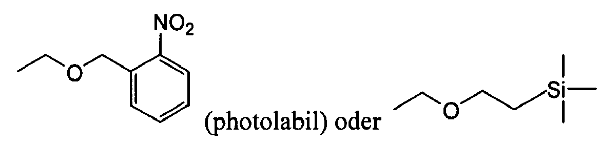
B steht in Formel II für eine Nucleobase wie die Purin-Derivate Adenin und Guanin sowie die Pyrimidine Cytosin und Uracil.B in formula II stands for a nucleobase such as the purine derivatives adenine and guanine as well as the pyrimidines cytosine and uracil.
Bevorzugt sind allerdings Sondenmoleküle mit selektiv spaltbaren Bindungen, die unter normalen atmosphärischen, Temperatur-, und Licht-Bedingungen stabil sind.However, preferred are probe molecules with selectively cleavable bonds that are stable under normal atmospheric, temperature, and light conditions.
Bei einer alternativen Ausführungsform ist die labile Bindung selektiv durch enzymatische Methoden spaltbar. Beispiele für Nukleotidbausteine, die derartige labile Bindungen umfassen, sind in US 4,775,619 und US 4,876,187 beschrieben. Enzymatische Methoden zur Spaltung der selektiv spaltbaren Bindung sind allerdings im Rahmen der vorliegenden Erfindung weniger bevorzugt, da enzymatische Aktivitäten durch die Nähe der selektiv spaltbaren Bindung zur Oberfläche aufgrund der Immobilisierung der Sondenmoleküle stark behindert werden. Folglich weist eine enzymatische Spaltungsreaktion nur eine sehr niedrige Effizienz auf, was einen unerwünschten hohen Signalhintergrund durch fälschlicherweise positive Messergebnisse zur Folge hat. Somit kann bei einer bevorzugten Ausführungsform des erfindungsgemäßen Sonden-Arrays die selektiv spaltbare Bindung nicht durch enzymatische Methoden selektiv gespalten werden.In an alternative embodiment, the labile bond is selectively cleavable by enzymatic methods. Examples of nucleotide building blocks comprising such labile bonds are described in US 4,775,619 and US 4,876,187. Enzymatic methods for cleavage of the selectively cleavable bond, however, are less preferred in the context of the present invention, since enzymatic activities are greatly hindered by the proximity of the selectively cleavable bond to the surface due to the immobilization of the probe molecules. Consequently, an enzymatic cleavage reaction has only a very low efficiency, which results in an undesirably high signal background due to falsely positive measurement results. Thus, in a preferred embodiment of the probe array of the invention, the selectively cleavable bond can not be selectively cleaved by enzymatic methods.
Bei einer weiteren bevorzugten Ausführungsform des erfindungsgemäßen Sonden-Arrays befindet sich die selektiv spaltbare Bindung ungefähr in der Mitte zwischen der Stelle der Immobilisierung der Sonde auf der Array-Oberfläche und der Position der Markierung der Sonde. Somit wird gewährleistet, dass die Wahrscheinlichkeit der Wechselwirkung des Targets mit dem immobilisierten Sondenfragment, welches dem nach der Bindungsspaltung an der Oberfläche verbleibenden Rest der Sonde entspricht, wesentlich vermindert bzw. nahezu ausgeschlossen ist. Befindet sich die selektiv spaltbare Bindung dagegen zu nahe an der Array-Oberfläche, so ist der Komplex aus Sonden- und Targetmolekül nach der Spaltung nicht mehr ausreichend stabilisiert, da die Hybridisierung des Targets mit dem an der Array-Oberfläche immobilisierten Sondenfragments nicht stabil genug ist. Dies würde zu fälschlicherweise negativen Messergebnissen führen.In a further preferred embodiment of the probe array according to the invention, the selectively cleavable bond is located approximately in the middle between the point of immobilization of the probe on the array surface and the position of the label of the probe. This ensures that the probability of the interaction of the target with the immobilized probe fragment which corresponds to the remainder of the probe remaining after the bond cleavage on the surface is substantially reduced or almost excluded. On the other hand, if the selectively cleavable bond is too close to the array surface, then the complex of probe and target molecule is no longer sufficiently stabilized after cleavage since hybridization of the target to the probe fragment immobilized on the array surface is not sufficiently stable , This would lead to erroneously negative measurement results.
Wie bereits vorstehend erwähnt, ist die Markierung, die an die Targets oder Sonden gekoppelt ist, vorzugsweise eine detektierbare Einheit oder eine über eine Ankergruppe an die Targets oder Sonden gekoppelte detektierbare Einheit. Hinsichtlich der Möglichkeiten der Detektion bzw. der Markierung ist das erfindungsgemäße Verfahren äußerst flexibel. So ist das erfindungsgemäße Verfahren mit einer Vielzahl physikalischer, chemischer oder biochemischer Detektionsverfahren kompatibel. Voraussetzung ist lediglich, dass die zu detektierende Einheit bzw. Struktur direkt an eine Sonde oder ein Target, beispielsweise ein Oligonukleotid gekoppelt bzw. über eine mit dem Oligonukleotid koppelbare Ankergruppe verknüpft werden kann.As already mentioned above, the label coupled to the targets or probes is preferably a detectable entity or a detectable entity coupled via an anchor group to the targets or probes. With regard to the possibilities of detection or marking, the method according to the invention is extremely flexible. Thus, the method of the invention is compatible with a variety of physical, chemical or biochemical detection methods. The only requirement is that the unit or structure to be detected can be coupled directly to a probe or a target, for example an oligonucleotide, or linked via an anchor group which can be coupled to the oligonucleotide.
Die Detektion der Markierung kann auf Fluoreszenz, Magnetismus, Ladung, Masse, Affinität, enzymatischer Aktivität, Reaktivität, einer Goldmarkierung u.dgl. beruhen. So kann die Markierung beispielsweise auf der Verwendung von Fluorophor-markierten Strukturen bzw. Bausteinen basieren. In Verbindung mit der Fluoreszenz-Detektion kann die Markierung ein beliebiger an Targets oder Sonden während oder nach deren Synthese koppelbarer Farbstoff sein. Beispiele hierfür sind Cy-Farbstoffe (Amersham Pharmacia Biotech, Uppsala, Schweden), Alexa-Farbstoffe, Texas-Rot, Fluorescein, Rhodamin (Molecular Probes, Eugene, Oregon, USA), Lanthanide wie Samarium, Ytterbium und Europium (EG&G, Wallac, Freiburg, Deutschland).The detection of the label may be based on fluorescence, magnetism, charge, mass, affinity, enzymatic activity, reactivity, a gold label and the like. based. For example, the label may be based on the use of fluorophore-labeled structures or building blocks. In conjunction with fluorescence detection, the label may be any dye that can be coupled to targets or probes during or after their synthesis. Examples include Cy dyes (Amersham Pharmacia Biotech, Uppsala, Sweden), Alexa dyes, Texas Red, fluorescein, rhodamine (Molecular Probes, Eugene, Oregon, USA), lanthanides such as samarium, ytterbium and europium (EG & G, Wallac, Freiburg, Germany).
Neben Fluoreszenz-Markern können im Rahmen der vorliegenden Erfindung als Markierung bzw. als Detektiereinheit, die mit den Targets bzw. Sonden gekoppelt ist, auch Lumineszenz-Marker, Metall-Marker, Enzym-Marker, radioaktive Marker und/oder polymere Marker eingesetzt werden.In addition to fluorescent markers, luminescent markers, metal markers, enzyme markers, radioactive markers and / or polymeric markers can be used in the context of the present invention as marking or as detection unit which is coupled to the targets or probes.
Ebenso kann eine Nukleinsäure als Markierung (Tag) genutzt werden, die durch Hybridisierung mit einer markierten Reporter detektiert werden kann (Sandwich-Hybridisierung). Einsatz zum Nachweis des Tags finden diverse molekularbiologische Nachweisreaktionen wie Primer-Extension, Ligation und RCA.Likewise, a nucleic acid can be used as tag (Tag), which can be detected by hybridization with a labeled reporter (sandwich hybridization). Use for detection of the tag find various molecular biological detection reactions such as primer extension, ligation and RCA.
Bei einer alternativen Ausführungsform des erfindungsgemäßen Verfahrens ist die detektierbare Einheit über eine Ankergruppe mit den Targets oder Sonden gekoppelt. Bevorzugt verwendete Ankergruppen sind Biotin, Digoxygenin u.dgl. Die Ankergruppe werden in einer anschließenden Reaktion mit spezifisch bindenden Komponenten, beispielsweise Streptavidin-Konjugaten oder Antikörper-Konjugaten umgesetzt, die selbst detektierbar sind oder eine detektierbare Reaktion auslösen. Bei Einsatz von Ankergruppen kann die Umsetzung der Ankergruppen in detektierbare Einheiten vor, während oder nach Zugabe der Probe umfassend die Targets bzw. ggf. vor, während oder nach der Spaltung der selektiv spaltbarer Bindung in den Sonden erfolgen.In an alternative embodiment of the method according to the invention, the detectable unit is coupled via an anchor group with the targets or probes. Preferably used anchor groups are biotin, digoxygenin and the like. The anchor group is reacted in a subsequent reaction with specific binding components, for example streptavidin conjugates or antibody conjugates, which are themselves detectable or trigger a detectable reaction. When using anchor groups, the conversion of the anchor groups into detectable units before, during or after the addition of the sample comprising the targets or, if appropriate, before, during or after the cleavage of the selectively cleavable bond in the probes can take place.
Die Markierung kann erfindungsgemäß auch durch Wechselwirkung eines markierten Moleküls mit den Sonden-Molekülen erfolgen. Beispielsweise kann die Markierung durch Hybridisierung eines wie vorstehend beschrieben markierten Oligonukleotids mit einer Oligonukleotid-Sonde bzw. einem Oligonukleotid-Target erfolgen.The labeling according to the invention can also be effected by interaction of a labeled molecule with the probe molecules. For example, the labeling can be carried out by hybridization of an oligonucleotide labeled as described above with an oligonucleotide probe or an oligonucleotide target.
Weitere im Rahmen der vorliegenden Erfindung geeignete Markierungsverfahren und Nachweissysteme sind beispielsweise in Lottspeich und Zorbas, Bioanalytik, Spektrum Akademischer Verlag, Heidelberg, Berlin, 1998, Kapitel 23.3 und 23.4 beschrieben.Other suitable labeling methods and detection systems in the context of the present invention are described, for example, in Lottspeich and Zorbas, Bioanalytik, Spektrum Akademischer Verlag, Heidelberg, Berlin, 1998, Chapter 23.3 and 23.4.
Bei einer bevorzugten Ausführungsform des erfindungsgemäßen Verfahrens werden Nachweisverfahren eingesetzt, die im Ergebnis ein Addukt mit einem bestimmten Löslichkeitsprodukt, das eine Präzipitation zur Folge hat, liefern. Zur Markierung werden insbesondere Substrate eingesetzt, die in ein schwer lösliches, üblicherweise gefärbtes Produkt umgesetzt werden können. Beispielsweise können bei dieser Markierungsreaktion Enzyme verwendet werden, die den Umsatz eines Substrats in ein schwer lösliches Produkt katalysieren. Eine Reihe von in Frage kommenden Reaktionen, die geeignet sind, um zu einem Niederschlag an Array-Elementen zu führen, sowie Möglichkeiten für die Detektion des Niederschlags sind beispielsweise in der internationalen Patentanmeldung WO 00/72018 und in der internationalen Patentanmeldung WO 02/02810 beschrieben, auf deren Inhalt hiermit ausdrücklich Bezug genommen wird.In a preferred embodiment of the process according to the invention, detection methods are used which, as a result, provide an adduct with a specific solubility product which results in precipitation. In particular substrates are used for labeling, which can be converted into a sparingly soluble, usually colored product. For example, in this labeling reaction, enzymes can be used which reduce the conversion of a substrate into a poorly soluble product catalyze. A number of suitable reactions suitable for precipitating on array elements and ways of detecting precipitation are described, for example, in International Patent Application WO 00/72018 and International Patent Application WO 02/02810 , the contents of which are hereby expressly incorporated by reference.
Bei einer besonders bevorzugten Ausführungsform des erfindungsgemäßen Verfahrens sind die gebundenen Targets mit einer Markierung versehen, die die Reaktion eines löslichen Substrats zu einem schwer löslichen Niederschlag auf dem Array-Element katalysiert, an dem einen Sonden/Target-Wechselwirkung stattgefunden hat bzw. die als Kristallisationskeim für die Umwandlung eines löslichen Substrats zu einem schwer löslichen Niederschlag auf dem Array-Element wirkt, an dem eine Sonden/Target-Wechselwirkung stattgefunden hat.In a particularly preferred embodiment of the method according to the invention, the bound targets are provided with a label which catalyzes the reaction of a soluble substrate to a sparingly soluble precipitate on the array element on which a probe / target interaction has taken place or as a crystallization nucleus for the conversion of a soluble substrate to a sparingly soluble precipitate on the array element where a probe / target interaction has occurred.
Der Einsatz des erfindungsgemäßen Verfahrens erlaubt auf diese Weise die simultane qualitative und quantitative Analyse einer Vielzahl von Sonden/Target-Wechselwirkungen, wobei einzelne Array-Elemente mit einer Größe von ≤ 1000 µm, vorzugsweise von ≤ 100 µm und besonders bevorzugt von ≤ 50 µm realisiert werden können.The use of the method according to the invention allows in this way the simultaneous qualitative and quantitative analysis of a large number of probe / target interactions, wherein individual array elements with a size of ≦ 1000 μm, preferably ≦ 100 μm and particularly preferably ≦ 50 μm are realized can be.
In der Immunzytochemie und bei immunologischen Mikrotiterplatten-basierten Tests ist der Einsatz von enzymatischen Markierungen bekannt (siehe E. Lidell und I. Weeks, Antibody Technology, BIOS Scientific Publishers Limited, 1995). So katalysieren beispielsweise Enzyme den Umsatz eines Substrats in ein schwerlösliches, in aller Regel gefärbtes Produkt.In immunocytochemistry and immunological microtiter plate-based assays, the use of enzymatic labels is known (see E. Lidell and I. Weeks, Antibody Technology, BIOS Scientific Publishers Limited, 1995). For example, enzymes catalyze the conversion of a substrate into a sparingly soluble, generally colored product.
Eine weitere Möglichkeit des Nachweises molekularer Wechselwirkungen auf Arrays besteht im Einsatz von Metallmarkierungen. Hierbei werden beispielsweise kolloidales Gold oder definierte Goldcluster mit den Targets gekoppelt, ggf. über bestimmte Vermittlermoleküle wie Streptavidin. Die durch die Goldmarkierung entstehende Färbung wird vorzugsweise durch nachfolgende Reaktion mit unedleren Metallen wie z.B. Silber verstärkt, wobei die mit den Targets gekoppelte Goldmarkierung als Kristallisationskeim bzw. Katalysator beispielsweise für die Reduktion von Silberionen zu einem Silberniederschlag wirkt. Die mit Goldmarkierungen gekoppelten Targets werden im Folgenden auch als Goldkonjugate bezeichnet.Another way of demonstrating molecular interactions on arrays is to use metal tags. Here, for example, colloidal gold or defined gold clusters are coupled to the targets, possibly via specific mediator molecules such as streptavidin. The color resulting from the gold marking is preferably enhanced by subsequent reaction with less noble metals such as silver, with the coupled to the targets gold marking acts as a crystallization nucleus or catalyst, for example, for the reduction of silver ions to a silver precipitate. The gold target-coupled targets are also referred to below as gold conjugates.
Bei dieser Ausführungsform des erfindungsgemäßen Verfahrens kann auch eine relative Quantifizierung der Sonden-/Target-Wechselwirkung erfolgen. Die relative Quantifizierung der Konzentration der gebundenen Targets auf einem Sonden-Array durch Nachweis eines Präzipitats bzw. eines Niederschlags erfolgt über die Konzentration der mit den Targets gekoppelten Markierungen, die die Reaktion eines löslichen Substrats zu einem schwerlöslichen Niederschlag auf dem Array-Element, an dem eine Sonden/Target-Wechselwirkung stattgefunden hat, katalysieren bzw. als Kristallisationskeim für derartige Reaktionen wirken. Beispielsweise beträgt im Fall von mit Nanogold markierten HPLCgereinigten Oligonukleotidsonden das Verhältnis von gebundenem Target zu Goldpartikel 1:1. In anderen Ausführungsformen der vorliegenden Erfindung kann es ein Vielfaches oder auch einen Bruchteil davon betragen.In this embodiment of the method according to the invention, a relative quantification of the probe / target interaction can also take place. The relative quantification of the concentration of bound targets on a probe array by detection of a precipitate is via the concentration of labels coupled to the targets, which is the reaction of a soluble substrate to a sparingly soluble precipitate on the array element where a probe / target interaction has occurred, catalyze or act as a seed for such reactions. For example, in the case of nanogold-labeled HPLC-purified oligonucleotide probes, the ratio of bound target to gold particle is 1: 1. In other embodiments of the present invention, it may be a multiple or a fraction thereof.
Die Detektion bei dieser Ausführungsform des erfindungsgemäßen Nachweisverfahrens erfolgt somit durch Messung der Durchlichtabsorption oder Auflichtreflektion, die durch den Niederschlag hervorgerufen wird, der auf den Array-Elementen, an denen einen Sonden/Target-Wechselwirkung stattgefunden, durch die katalytische Wirkung der mit den gebundenen Targets gekoppelten Markierung erzeugt wird.The detection in this embodiment of the detection method according to the invention thus takes place by measuring the transmitted light absorption or incident light reflection caused by the precipitate deposited on the array elements on which a probe / target interaction occurred by the catalytic action of the bound targets coupled marking is generated.
Die Lichtabsorption wird im Fall der Kopplung von kolloidalem Gold oder definierten Goldcluster mit den Targets bereits durch die Gegenwart dieser metallischen Markierungen hervorgerufen. Zur Verstärkung der Lichtabsorption wird allerdings vorzugsweise katalytisch durch derartige Wechselwirkungshybride, d.h. die mit einer Markierung wie beispielsweise kolloidalem Gold oder definierten Goldelustern versehene Targets, ein nicht transparentes Präzipitat abgeschieden. Als besonders vorteilhaft hat sich im Fall von Goldkonjugaten die Verwendung von Silber als Präzipitat herausgestellt.The absorption of light in the case of the coupling of colloidal gold or defined gold clusters with the targets is already caused by the presence of these metallic labels. However, to enhance light absorption, it is preferable that catalytically by such interaction hybrids, ie, the targets provided with a label such as colloidal gold or goldlobes, be non-transparent Precipitate deposited. In the case of gold conjugates, the use of silver as precipitate has proven to be particularly advantageous.
Im Folgenden wird der qualitative und/oder quantitative Nachweis der Sonden-/Target-Wechselwirkung durch Messung der Durchlichtabsorption anhand eines Beispiel erläutert. Selbstverständlich ist die im Folgenden beschriebene Vorgehensweise nicht auf die vorstehend beschriebene Silber/Gold-Färbung beschränkt, sondern kann entsprechend auf alle Nachweisverfahren angewendet werden, bei denen die gebundenen Targets mit einer Markierung versehen sind, die die Reaktion eines löslichen Substrats zu einem schwer löslichen Niederschlag auf dem Array-Element katalysiert, an dem einen Sonden/Target-Wechselwirkung stattgefunden hat bzw. die als Kristallisationskeim für die Umwandlung eines löslichen Substrats zu einem schwer löslichen Niederschlag auf dem Array-Element wirkt, an dem eine Sonden/Target-Wechselwirkung stattgefunden hat.In the following, the qualitative and / or quantitative detection of the probe / target interaction by measuring the transmitted light absorption will be explained by way of example. Of course, the procedure described below is not limited to the silver / gold coloration described above, but can be applied to all detection methods in which the bound targets are marked, which is the reaction of a soluble substrate to a sparingly soluble precipitate catalyzes on the array element on which a probe / target interaction has occurred or acts as a seed for the conversion of a soluble substrate to a sparingly soluble precipitate on the array element, on which a probe / target interaction has taken place ,
Zunächst wird das Targetmolekül z.B. mittels PCR biotiniliert. Das PCR-Produkt wird gegen eine Substanzbibliothek (102), beispielsweise eine DNA-Bibliothek, hybridisiert. Anschließend werden dem erfindungsgemäßen Reaktionsgefäß (1) Streptavidinfunktionalisierte Goldkügelchen zugegeben, die mit den biotinilierten Hybriden, beispielsweise DNA-Hybriden reagieren. An den nun spezifisch an der Oberfläche gebundenen Goldkügelchen kann ein Silberniederschlag erzeugt werden, indem beispielsweise Silbernitrat mit Hydrochinon unter der katalytischen Wirkung von Gold reduziert wird (siehe u.a. WO 00/72018, DE 100 33 334.6, M.A. Hayat, Immunogold-Silver Staining, CRC Press, New York, 1995).First, the target molecule is e.g. biotinylated by PCR. The PCR product is hybridized against a substance library (102), for example a DNA library. Subsequently, the reaction vessel according to the invention (1) streptavidin-functionalized gold beads are added, which react with the biotinylated hybrids, such as DNA hybrids. A silver precipitate can be produced on the gold beads, which are now bound specifically on the surface, for example by reducing silver nitrate with hydroquinone under the catalytic action of gold (see, inter alia, WO 00/72018,
Die Lichtabsorption durch das Silberpräzipitat hängt von der Menge des abgeschiedenen Silbers ab. Folglich kann die Lichtintensität I, die das Präzipitat durchstrahlt, nach einem dem Lambert-Beerschen Gesetz ähnlichen Funktion berechnet werden: 
Dabei ist I die Lichtintensität nach der Absorption, I0 die Lichtintensität vor der Absorption, a ein Absorptionskoeffizient multipliziert mit der Abschattung pro Flächeneinheit b durch das Silberpräzipitat. Als Messgrößen stehen die Intensität I und die Zeit t zur Verfügung. Diese Messgrößen erhält man, indem das Trägerelement mit der Substanzbibliothek beleuchtet wird und das durchstrahlte Licht mit einer Kamera aufgenommen wird (siehe Abbildung 19). Diese Aufnahme wird in regelmäßigen Abständen wiederholt, während die Silberabscheidung durchgeführt wird. Die Helligkeitswerte der einzelnen Bibliotheksregionen (Spots) werden für jede Aufnahme ausgewertet, wodurch die Intensität I eines jeden Spot erhalten wird. Diese Helligkeitswerte können mittels Standardsoftware, wie zum Beispiel IconoClust® (Clondiag, Jena, Deutschland) automatisch berechnet werden. Durch Auftragen von I/I0 gegen die Zeit t erhält man die in Abbildung 20 dargestellten Messkurven. Das Lambert-Beersche Gesetz entsprechend der Gleichung (I) kann mit den derart erhaltenen Silberabscheidungszeitreihen auf folgende Weise in Zusammenhang gebracht werden.Where I is the light intensity after absorption, I 0 is the light intensity before absorption, a is an absorption coefficient multiplied by the shading per unit area b by the silver precipitate. The measured quantities are intensity I and time t. These measured quantities are obtained by illuminating the carrier element with the substance library and recording the transmitted light with a camera (see Figure 19). This photograph is repeated at regular intervals while the silver deposition is carried out. The brightness values of the individual library regions (spots) are evaluated for each shot, whereby the intensity I of each spot is obtained. These brightness values can be automatically calculated using standard software, such as IconoClust® (Clondiag, Jena, Germany). By plotting I / I 0 against time t, the curves shown in Figure 20 are obtained. The Lambert-Beer law corresponding to the equation (I) can be related to the silver deposition time series thus obtained in the following manner.
Die Fläche F, die ein Silberkügelchen abschattet, beträgt: ![]()
![]()
Da die Abscheidungsgeschwindigkeit pro Flächenelement für einen Spot als konstant angenommen werden kann, wächst der Radius r der Silberkügelchen ebenfalls mit konstanter Geschwindigkeit: 
Die Abschattung pro Flächeneinheit b durch das Silberpräzipitat ist proportional zur der Zahl der Silberkügelchen pro Flächeneinheit N, der Abschattungsfläche pro Silberkügelchen F und einer Konstante k. ![]()
![]()
Damit berechnet sich die Funktion für die Intensität I in Abhängigkeit von der Zeit t zu ![]()
wobei a' eine unbekannte zusammengesetzte Silberabsorptionskonstante ist.Thus, the function for the intensity I is calculated as a function of the time t ![]()
where a 'is an unknown composite silver absorption constant.
Für jede Silberabscheidungsreaktion muss eine eigene Abscheidungsrate angenommen werden, so auch für die unspezifische Reaktion an der Oberfläche: ![]()
wobei a' H die unspezifische Silberabsorptionskonstante ist.For each silver deposition reaction, a separate deposition rate must be assumed, as well as for the nonspecific reaction at the surface: ![]()
where a ' H is the nonspecific silver absorption constant.
An jedem Spot i, findet also sowohl eine spezifische Abscheidungsreaktion als auch eine unspezifische Abscheidungsreaktion statt: ![]()
wobei O ein geräteabhängiger Offsetwert ist.At each spot i , both a specific deposition reaction and a nonspecific deposition reaction take place: ![]()
where O is a device-dependent offset value.
Die Zahl der Goldkügelchen, die pro Flächeneinheit abgeschieden werden, hängt einerseits von der Menge an mit Goldkügelchen markierten Targets und andererseits von der Bindungsstärke der Targets, beispielsweise der Target-DNA, mit den Sonden, beispielsweise der Spot-DNA, ab. Liegt kein Target in der Probe vor, das mit einer Sonde auf dem entsprechenden Array-Element wechselwirkt, so kommt es auch nicht zur Abscheidung von Goldkügelchen auf der Oberfläche dieses Array-Elements bzw. Spots. Ist die Bindung zwischen Sonde und Target schwach, so werden sich nur sehr wenige Goldkügelchen an der Oberfläche dieses Array-Elements absetzen.The number of gold beads deposited per unit area depends, on the one hand, on the amount of gold globule-labeled targets and, on the other, on the Binding strength of the targets, for example the target DNA, with the probes, for example the spot DNA. If there is no target in the sample that interacts with a probe on the corresponding array element, then gold beads do not deposit on the surface of this array element or spot. If the bond between probe and target is weak, only very few gold beads will settle on the surface of this array element.
Da b und damit a' direkt proportional zur Goldkügelchen - und damit Silberkügelchenanzahl N ist, stellt a' ein Maß für die Konzentration der Target-DNA und der Bindungsstärke der Target-DNA am Array-Element bzw. Spot i da.Since b and thus a 'are directly proportional to the gold beads - and thus silver bead number N , a' represents a measure of the concentration of the target DNA and the binding strength of the target DNA on the array element or spot i da.
In Abbildung 20 sind die Silberabscheidungszeitreihen zweier Spots dargestellt, die gegen eine Target-DNA hybridisiert werden. Die DNA-Sonden der Spots unterscheiden sich um eine Base, so dass die Target-DNA zu der Sonde des einen Spot perfekt komplementär ist, während sie zu der Sonde des anderen Spots einen Mismatch aufweist. Aus den beiden Messkurven lässt sich durch nichtlineare Regression mit Hilfe der Gleichung (VI) die Silberabsorptionskonstante a' berechnen. Im Falle des Perfect Match beträgt sie 2,566 x 10-6 sek-2 und im Falle des Mismatch 4,83 x 10⁻⁷ sek-2 (siehe auch Beispiel 2). Die beiden Konstanten unterscheiden sich damit um fast eine Zehnerpotenz. Damit kann die Berechnung der Konstanten a' als signifikante Messgröße für die Bindungsstärke und die Konzentration der Target-DNA an einem Spot genutzt werden. Des Weiteren kann man aus der Konstanten a' die Zeitkonstante τ der Abscheidungsreaktion bestimmen: ![]()
![]()
Durch die Regression können als weitere Parameter I0 und O ermittelt werden. Mit der Lichtintensität I0 können Beleuchtungsinhomogenitäten der DNA-Bibliothek korrigiert werden. Alternativ kann mittels des Abbildes der gesamten DNA-Bibliothek zum Zeitpunkt t = 0 eine Flatfieldkorrektur aller weiteren Bilder, die für die Zeitreihe zu einem späteren Zeitpunkt aufgenommen wurden, vorgenommen werden. Anhand des Parameters O lässt sich die Validität einer Messung abschätzen.By regression can be determined as further parameters I 0 and O. With the light intensity I 0 , illumination inhomogeneities of the DNA library can be corrected. Alternatively, by means of the image of the entire DNA library at the time t = 0 a flat field correction of all other images taken for the time series at a later time can be made. The validity of a measurement can be estimated by means of parameter O.
Da die korrekte Anpassung einer Exponentialfunktion an die Messwerte einen nicht-linearen Regressionsalgorithmus, beispielsweise eine nicht-lineare Regression nach Marquardt (H.R. Schwarz, Numerische Mathematik, Teubner Verlag, Stuttgart, Deutschland, 1998) erfordert, kann es vorteilhaft sein, auf eine weniger genaue, aber dafür robustere und daher lineare Methode zur Bestimmung der Messwerte aus den Zeitreihen zuzugreifen. Dazu werden die Zeitwerte quadriert und die Intensitätsmesswerte logarithmiert. Die so erhaltenen Werte werden dann an eine lineare Gleichung 1. Gerades angepasst. Die dabei erhaltenen Regressionsparameter können als Messwert und zur Testung der Validität herangezogen werden. Beleuchtungsinhomogenitäten lassen sich bei Verwendung einer linearen Methode über I0 nicht mehr korrigieren, es verbleibt aber die Möglichkeit der Flatfieldkorrektur.Since the correct adaptation of an exponential function to the measured values requires a non-linear regression algorithm, for example a non-linear regression according to Marquardt (HR Schwarz, Numerische Mathematik, Teubner Verlag, Stuttgart, Germany, 1998), it may be advantageous to use a less accurate regression algorithm but to use a more robust and therefore linear method to determine the measurements from the time series. For this, the time values are squared and the intensity measured values logarithmized. The values thus obtained are then adapted to a
Eine weitere Variante der Auswertung besteht darin, nach einer festgelegten Zeit die Grauwerte der einzelnen Spots direkt als Messwerte zu verwenden. Dieses Verfahren hat allerdings die Nachteile, dass nicht im Voraus beurteilt werden kann, welcher Zeitpunkt zur Auswertung optimal ist und dass die Messwerte eine geringere statistische Sicherheit aufweisen. Darüber hinaus lässt sich eine etwaige Beleuchtungsinhomogenität nur über eine Flatfieldkorrektur durchführen.Another variant of the evaluation consists in using the gray values of the individual spots directly as measured values after a specified time. However, this method has the disadvantages that it is not possible to judge in advance which time is optimal for the evaluation and that the measured values have a lower statistical certainty. In addition, any illumination inhomogeneity can only be performed via a flat field correction.
Bei einer weiteren bevorzugten Ausführungsform des erfindungsgemäßen Verfahrens wird somit in Schritt c) der zeitliche Verlauf der Niederschlagsbildung an den Array-Elementen in Form von Signalintensitäten detektiert. Auf diese Weise kann eine genaue Bestimmung der relativen quantitativen Menge an gebundenen Targets gewährleistet werden. Eine derartige Vorgehensweise ist ausführlich in der internationalen Patentanmeldung WO 02/02810 beschrieben.In a further preferred embodiment of the method according to the invention, the time profile of the formation of precipitates on the array elements in the form of signal intensities is thus detected in step c). In this way, an accurate determination of the relative quantitative amount of bound targets can be ensured. Such a procedure is described in detail in international patent application WO 02/02810.
Wie bereits vorstehend erwähnt, sind die Targets vorzugsweise mit Markierungen versehen, die die Reaktion eines löslichen Substrats zu einem schwer löslichen Niederschlag auf dem Array-Element, an dem eine Sonden/Target-Wechselwirkung stattgefunden hat, katalysieren, bzw. Kristallisationskeim für derartige Reaktionen wirken.As mentioned above, the targets are preferably provided with labels that catalyze the reaction of a soluble substrate to a sparingly soluble precipitate on the array element where probe / target interaction has taken place, or nucleation sites for such reactions ,
Dabei können bei einer Ausführungsform der vorliegenden Erfindung die Targets direkt mit derartigen Markierungen versehen sein.In this case, in one embodiment of the present invention, the targets can be provided directly with such markings.
Alternativ wird auf eine direkte Markierung der Targets verzichtet und die Markierung erfolgt über Sandwich-Hybridisierung oder Sandwich-Reaktionen mit der mit dem Target wechselwirkenden Sonde und einer markierten Verbindung. Beispiele für eine derartige Vorgehensweise sind:
- Sandwich-Hybridisierung mit einem zur Targetsequenz komplementären markierten Oligonukleotid.
- Sandwich-Hybridisierung von in Kettenform mit der Targetsequenz hybridisierenden markierten Oligonukleotiden: Unter in Kettenform mit der Targetsequenz hybridisierenden markierten Oligonukleotiden wird im Rahmen der vorliegenden Erfindung ein Satz von markierten Oligonukleotiden verstanden, von denen mindestens eines Komplementarität sowohl zur Targetsequenz als auch zu einem weiteren Oligonukleotid aufweist. Die anderen Oligonukleotide sind selbstkomplementär bzw. wechselseitig zueinander komplementär, so dass während der Hybridisierung eine Kette von an der Targetsequenz gebundenen markierten Oligonukleotiden entsteht.
- Sandwich-Hybridisierung mit einem zur Targetsequenz komplementären Oligonukleotid, das mit einer vielfach markierten Struktur, beispielsweise einem Dendrimer, beschrieben z.B. in WO 99/10362, gekoppelt ist.
- Sandwich hybridization with a labeled oligonucleotide complementary to the target sequence.
- Sandwich hybridization of labeled oligonucleotides hybridizing in chain form with the target sequence: In the context of the present invention, the labeled oligonucleotides hybridizing in chain form with the target sequence is understood as meaning a set of labeled oligonucleotides of which at least one has complementarity both with the target sequence and with another oligonucleotide , The other oligonucleotides are self-complementary or mutually complementary to one another such that a chain of labeled oligonucleotides bound to the target sequence is formed during the hybridization.
- Sandwich hybridization with an oligonucleotide complementary to the target sequence, which is coupled to a multi-labeled structure, for example a dendrimer, described for example in WO 99/10362.
Eine weitere bevorzugte Möglichkeit der Kopplung der Targets mit einer Markierung stellt das synthetische oder enzymatische Anfügen eines homopolymeren Bereichs, beispielsweise einer polyA-Sequenz, an die Targets unter Bildung einer fortlaufenden Sequenz dar, wie es beispielsweise in US 6,103,474 beschrieben ist. Bei dieser Ausführungsform erfolgt die Markierung vorzugsweise über Sandwich-Hybridisierung mit einem zur HomopolymerSequenz komplementären markierten Oligonukleotid mit den vorstehend beschriebenen Variationen.Another preferred possibility of coupling the targets with a label is the synthetic or enzymatic addition of a homopolymeric region, for example a polyA sequence, to the targets to form a continuous sequence, as described, for example, in US Pat. No. 6,103,474. In this embodiment, labeling is preferably by sandwich hybridization with a homopolymer sequence-complementary labeled oligonucleotide having the variations described above.
Bei einer weiteren bevorzugten Ausführungsform der vorliegenden Erfindung erfolgt eine Signalamplifikation durch Amplifikation von Teilen der an die Targets angefügten Homopolymersequenz bei gleichzeitigem Einbau von markierten Basen, insbesondere bevorzugt über einen RCA-Mechanismus durch Verwendung eines zirkulären einzelsträngigen Templates, das Komplementarität zur Homopolymersequenz aufweist.In a further preferred embodiment of the present invention, signal amplification takes place by amplification of parts of the homopolymer sequence attached to the targets with simultaneous incorporation of labeled bases, more preferably via an RCA mechanism by using a circular single-stranded template which has complementarity to the homopolymer sequence.
Die nachfolgende Tabelle 1 gibt, ohne den Anspruch zu erheben, vollständig zu sein, einen Überblick über eine Reihe von in Frage kommenden Reaktionen, die geeignet sind, um zu einem Niederschlag an Array-Elementen zu führen, an denen eine Wechselwirkung zwischen Target und Sonde erfolgt ist:
Die Markierung von biologischen Proben mit Enzymen bzw. Gold, insbesondere nanokristallinem Gold ist hinlänglich beschrieben (siehe u.a. F. Lottspeich und H. Zorbas, Bioanalytik, Spektrum Akademischer Verlag, Heidelberg, Berlin, 1998; E. Lidell und I. Weeks, Antibody Technology, BIOS Scientific Publishers Limited, 1995).The labeling of biological samples with enzymes or gold, in particular nanocrystalline gold, is well described (see, inter alia, F. Lottspeich and H. Zorbas, Bioanalytics, Spektrum Akademischer Verlag, Heidelberg, Berlin, 1998, E. Lidell and I. Weeks, Antibody Technology , BIOS Scientific Publishers Limited, 1995).
Weitere Möglichkeiten für den Nachweis der Sonde/Target-Wechselwirkungen über unlösliche Präzipitate bei dem erfindungsgemäßen Verfahren sind beschreiben in: Immunogold-Silver Staining, Principles, Methods and Applications, Hrsg.: M.A.Hayat, 1995, CRC Press; Eur J Immunogenet 1991 Feb-Apr;18(1-2):33-55 HLA-DR, DQ and DP typing using PCR amplification and immobilized probes. Erlich H, Bugawan T, Begovich AB, Scharf S, Griffith R, Saiki R, Higuchi R, Walsh PS. Department of Human Genetics, Cetus Corp., Emeryville, California 94608; Mol Cell Probes 1993 Jun;7(3):199-207 A combined modified reverse dot-blot and nested PCR assay for the specific non-radioactive detection of Listeria monocytogenes. Bsat N, Batt CA. Department of Food Science, Cornell University, Ithaca, NY 14853. Immunogenetics 1990;32(4):231-41 Erratum in: Immunogenetics 1991;34(6):413 Rapid HLA-DPB typing using enzymatically amplified DNA and nonradioactive sequence-specific oligonucleotide probes. Bugawan TL, Begovich AB, Erlich HA. Department of Human Genetics, Cetus Corporation, Emeryville, CA 94608. Hum Immunol 1992 Dec;35(4):215-22 Generic HLA-DRB1 gene oligotyping by a nonradioactive reverse dot-blot methodology. Eliaou JF, Palmade F, Avinens O, Edouard E, Ballaguer P, Nicolas JC, Clot J. Laboratory of Immunology, Saint Eloi Hospital, CHU Montpellier, France. J Immunol Methods 1984 Nov 30;74(2):353-60 Sensitive visualization of antigenantibody reactions in dot and blot immune overlay assays with immunogold and immunogold/silver staining. Moeremans M, Daneels G, Van Dijck A, Langanger G, De Mey J. Histochemistry 1987;86(6):609-15 Non-radioactive in situ hybridization. A comparison of several immunocytochemical detection systems using reflection-contrast and electron microscopy. Cremers AF, Jansen in de Wal N, Wiegant J, Dirks RW, Weisbeek P, van der Ploeg M, Landegent JE.Further possibilities for the detection of the probe / target interactions via insoluble precipitates in the method according to the invention are described in: Immunogold-Silver Staining, Principles, Methods and Applications, Ed .: MA Hayat, 1995, CRC Press; Eur J Immunogenet 1991 Feb-Apr; 18 (1-2): 33-55 HLA-DR, DQ and DP typing using PCR amplification and immobilized probes. Erlich H, Bugawan T, Begovich AB, Scharf S, Griffith R, Saiki R, Higuchi R, Walsh PS. Department of Human Genetics, Cetus Corp., Emeryville, California 94608; Mol Cell Probes 1993 Jun; 7 (3): 199-207 A combined modified reverse dot-blot and nested PCR assay for the specific non-radioactive detection of Listeria monocytogenes. Bsat N, Batt CA. Department of Food Science, Cornell University, Ithaca, NY 14853. Immunogenetics 1990; 32 (4): 231-41 Erratum in: Immunogenetics 1991; 34 (6): 413 Rapid HLA-DPB typing using enzymatically amplified DNA and nonradioactive sequence-specific oligonucleotide probes. Bugawan TL, Begovich AB, Erlich HA. Department of Human Genetics, Cetus Corporation, Emeryville, CA 94608. Hum Immunol 1992 Dec; 35 (4): 215-22 Generic HLA-DRB1 gene oligotyping by a nonradioactive reverse dot-blot methodology. Eliaou JF, Palmade F, Avinens O, Edouard E, Ballaguer P, Nicolas JC, Clot J. Laboratory of Immunology, Saint Eloi Hospital, CHU Montpellier, France. J Immunol Methods 1984 Nov 30; 74 (2): 353-60 Sensitive visualization of antigenic antibody reactions in dot and blot immune overlay assays with immunogold and immunogold / silver staining. Moeremans M, Daneels G, Van Dijck A, Langanger G, De Mey J. Histochemistry 1987; 86 (6): 609-15 Non-radioactive in situ hybridization. A comparison of several immunocytochemical detection systems using reflection-contrast and electron microscopy. Cremers AF, Jansen in the Wal N, Wiegant J, Dirks RW, Weisbeek P, van der Ploeg M, Landegent JE.
Im Rahmen der vorliegenden Erfindung sind u.a. folgende Varianten für den Nachweis der Sonde/Target-Wechselwirkungen über unlösliche Präzipitate denkbar.In the context of the present invention u.a. following variants for the detection of probe / target interactions on insoluble precipitates conceivable.
Bei einer Ausführungsform der vorliegenden Erfindung werden die Targets mit einem Katalysator, vorzugsweise einem Enzym versehen, das die Umwandlung eines löslichen Substrats in ein unlösliches Produkt katalysiert. Die Reaktion, die zur Bildung eines Niederschlags an den Array-Elementen führt, ist in diesem Fall die Umwandlung eines löslichen Substrats in ein unlösliches Produkt in Gegenwart eines mit den Targets gekoppelten Katalysators, vorzugsweise Enzyms. Das Enzym wird vorzugsweise ausgewählt aus der Gruppe, bestehend aus Meerettichperoxidase, alkalischer Phosphatase und Glucoseoxidase. Das lösliche Substrat wird vorzugsweise ausgewählt aus der Gruppe, bestehend aus 3,3'-Diaminobenzidin, 4-Chlor-1-naphthol, 3-Amino-9-ethylcarbazol, p-Phenylendiamin-HCl/Pyrocatechol, 3,3',5,5'-Tetramethylbenzidin, Naphthol/Pyronin, Bromchlorindoylphosphat, Nitrotetraazoliumblau und Phenazinmethosulfat. Beispielsweise wird ein farbloser löslicher Wasserstoffdonor, z.B. 3,3'-Diaminobenzidin, in Anwesenheit von Wasserstoffperoxid in ein unlösliches farbiges Produkt umgewandelt. Das Enzym Meerrettichperoxidase überträgt Wasserstoffionen aus den Donoren auf Wasserstoffperoxid unter Bildung von Wasser.In one embodiment of the present invention, the targets are provided with a catalyst, preferably an enzyme, which catalyzes the conversion of a soluble substrate to an insoluble product. The reaction leading to the formation of a precipitate on the array elements in this case is the conversion of a soluble substrate into an insoluble product in the presence of a catalyst coupled to the target, preferably an enzyme. The enzyme is preferably selected from the group consisting of horseradish peroxidase, alkaline phosphatase and Glucose oxidase. The soluble substrate is preferably selected from the group consisting of 3,3'-diaminobenzidine, 4-chloro-1-naphthol, 3-amino-9-ethylcarbazole, p-phenylenediamine-HCl / pyrocatechol, 3,3 ', 5, 5'-tetramethylbenzidine, naphthol / pyronine, bromochloroindoyl phosphate, nitrotetraazolium blue and phenazine methosulfate. For example, a colorless soluble hydrogen donor, eg, 3,3'-diaminobenzidine, is converted to an insoluble colored product in the presence of hydrogen peroxide. The horseradish peroxidase enzyme transfers hydrogen ions from the donors to hydrogen peroxide to form water.
Bei einer bevorzugten Ausführungsform der vorliegenden Erfindung ist die Reaktion, die zur Bildung eines Niederschlags an den Array-Elementen führt, die Bildung eines metallischen Niederschlags. Besonders bevorzugt ist die zur Bildung eines Niederschlags an den Array-Elementen führende Reaktion die chemische Reduktion einer Silberverbindung, vorzugsweise Silbernitrat, Silberlactat, Silberacetat oder Silbertartrat, zu elementarem Silber. Als Reduktionsmittel werden vorzugsweise Formaldehyd und/oder Hydrochinon eingesetzt.In a preferred embodiment of the present invention, the reaction which results in the formation of a precipitate on the array elements is the formation of a metallic precipitate. More preferably, the reaction leading to the formation of a precipitate on the array elements is the chemical reduction of a silver compound, preferably silver nitrate, silver lactate, silver acetate or silver tartrate, to elemental silver. The reducing agent used is preferably formaldehyde and / or hydroquinone.
Besonders bevorzugt erfolgt die Ausfällung der metallischen Verbindung in Gegenwart von mit den Targets gekoppelten Metallclustern bzw. kolloidalen Metallpartikeln, insbesondere Goldclustern oder kolloidalen Goldpartikeln. D.h. in diesem Fall stellen die Metallcluster bzw. kolloidalen Metallpartikel die mit den Targets gekoppelten Markierungen dar. Beispielsweise wird Silbernitrat in elementares Silber umgesetzt, wobei sich Silberionen aus der Lösung an Gold als Kristallisationskeim anlagern und in einem zweiten Schritt mit Hilfe eines Reduktionsmittels wie z.B. Formaldehyd oder Hydrochinon reduziert werden. Hierbei entsteht ein unlöslicher Niederschlag elementaren Silbers.Particularly preferably, the precipitation of the metallic compound takes place in the presence of metal clusters coupled to the targets or colloidal metal particles, in particular gold clusters or colloidal gold particles. That In this case, the metal clusters or colloidal metal particles represent the markers coupled to the targets. For example, silver nitrate is converted to elemental silver, with silver ions from the solution annealing to gold as nuclei and secondarily reduced by means of a reducing agent, e.g. Formaldehyde or hydroquinone can be reduced. This results in an insoluble precipitate of elemental silver.
Bei einer alternativen Ausführungsform erfolgt die Ausfällung der metallischen Verbindung in Gegenwart von mit den Targets gekoppelten Polyanionen. Wenn es sich beim Target selbst nicht um ein Poly-Anion handelt, dann besteht die Möglichkeit, ein solches zur Keimbildung einzusetzen. Das mit einem Poly-Anion markierte Target wird beispielweise einer Silbernitratlösung ausgesetzt. Dabei lagern sich die Silber-Kationen am Poly-Anion selektiv an. Danach werden mit einem Reduktionsmittel Silberionen in elementares Silber umgewandelt.In an alternative embodiment, the precipitation of the metallic compound occurs in the presence of polyanions coupled to the targets. If the target itself is not a poly-anion, then there is the possibility of such nucleation use. For example, the target labeled with a poly anion is exposed to a silver nitrate solution. The silver cations are selectively attached to the poly-anion. Thereafter, silver ions are converted into elemental silver with a reducing agent.
Die Kopplung der Enzyme bzw. Katalysatoren bzw. Metallcluster bzw. kolloidalen Metallpartikel bzw. Polyanionen an die Targets kann direkt oder über an die Targets gekoppelte Ankermoleküle erfolgen. Grundsätzlich besteht keine Notwendigkeit, das Target direkt mit den oben beschriebenen Markierungen zu versehen. Es besteht auch die Möglichkeit, über geeignete Ankermoleküle, z.B. Streptavidin, die an das Target gekoppelt werden, eine nachfolgende Ankopplung der Markierung zu erreichen.The coupling of the enzymes or catalysts or metal clusters or colloidal metal particles or polyanions to the targets can be carried out directly or via anchor molecules coupled to the targets. Basically, there is no need to provide the target directly with the tags described above. It is also possible, via suitable anchor molecules, e.g. Streptavidin, which are coupled to the target, to achieve subsequent coupling of the label.
Ein Konjugat bestehend aus dem jeweiligen Katalysator bzw. Kristallisationskeim und einem spezifischen Bindungspartner für das Ankermolekül erlaubt ebenfalls die Durchführung der oben beschriebenen Prozeduren. Die Reaktion, die zur Bildung eines Niederschlags an den Array-Elementen führt, ist dann die Bindung eines spezifischen Bindungspartners an ein an das Target gekoppeltes Ankermolekül darstellt.A conjugate consisting of the respective catalyst or crystallization nucleus and a specific binding partner for the anchor molecule also allows the implementation of the procedures described above. The reaction leading to the formation of a precipitate on the array elements is then the binding of a specific binding partner to an anchor molecule coupled to the target.
Derartige Bindungspartner/Ankermolekül-Paare werden vorzugsweise ausgewählt aus der Gruppe, bestehend aus Biotin/Avidin bzw. Streptavidin bzw. Anti-Biotin-Antikörper, Digoxigenin/Antidigoxigenin-Immunoglobulin, FITC/Anti-FITC-Immunoglobulin und DNP/Anti-DNP-Immunoglobulin.Such binding partner / anchor molecule pairs are preferably selected from the group consisting of biotin / avidin or streptavidin or anti-biotin antibodies, digoxigenin / anti-digoxigenin immunoglobulin, FITC / anti-FITC immunoglobulin and DNP / anti-DNP immunoglobulin ,
In jeder der vorstehend beschriebenen Ausführungsformen wird katalytisch ein lösliches Substrat in ein unlösliches und ausfallendes Produkt umgesetzt. Aufgrund der Nähe zur Oberfläche wird das Produkt unmittelbar an der Oberfläche abgeschieden und bildet einen festen, für diverse Wäschen unempfindlichen Niederschlag.In each of the embodiments described above, a soluble substrate is catalytically reacted into an insoluble and precipitating product. Due to the proximity to the surface, the product is deposited directly on the surface and forms a solid, insensitive to various washes precipitate.
Ferner ist es im Rahmen der vorliegenden Erfindung möglich, dass die Markierungen, insbesondere die Enzyme bzw. Metallcluster bzw. kolloidalen Metallpartikel bzw. Polyanionen, an die Targets vor, während oder nach der Wechselwirkung mit den Sonden gekoppelt werden.Furthermore, it is possible in the context of the present invention for the labels, in particular the enzymes or metal clusters or colloidal metal particles or polyanions, to be coupled to the targets before, during or after the interaction with the probes.
Bei einer bevorzugten Ausführungsform der vorliegenden Erfindung ist die Wechselwirkung zwischen dem Target und der Sonde eine Hybridisierung zwischen zwei Nukleotidsequenzen. Die Hybridisierung der Targets mit den auf einem Sonden-Array angeordneten Sonden findet nach einem der bekannten Standardprotokolle statt (siehe u.a. Lottspeich und Zorbas, 1998). Die entstandenen Hybride können durch kovalente Bindung, beispielsweise über Psoralen-Interkalation und nachfolgendes "Cross-Linking", oder wie in US 4,599,303 beschrieben, durch nichtkovalente Bindung, beispielsweise durch Bindung von Interkalatoren, stabilisiert werden.In a preferred embodiment of the present invention, the interaction between the target and the probe is a hybridization between two nucleotide sequences. The hybridization of the targets with the probes arranged on a probe array takes place according to one of the known standard protocols (see, inter alia, Lottspeich and Zorbas, 1998). The resulting hybrids can be stabilized by covalent bonding, for example via psoralen intercalation and subsequent cross-linking, or as described in US Pat. No. 4,599,303, by noncovalent binding, for example by binding of intercalators.
Im Anschluss an die Hybridisierung der Targets mit den auf einem Sonden-Array angeordneten Sonden bzw. der Markierung der hybridisierten Targets erfolgt üblicherweise ein Waschschritt, mit dem unspezifisch und dadurch schwächer gebundene Komponenten entfernt werden.Following the hybridization of the targets with the probes arranged on a probe array or the labeling of the hybridized targets, a washing step is usually carried out, with which non-specific and thus weakly bound components are removed.
Alternativ ist die Wechselwirkung zwischen dem Target und der Sonde eine Reaktion zwischen einer Antigenstruktur und dem entsprechenden Antikörper oder einem hypervariablen Abschnitt davon oder eine Reaktion zwischen einem Rezeptor und einem entsprechenden Liganden.Alternatively, the interaction between the target and the probe is a reaction between an antigenic structure and the corresponding antibody or a hypervariable portion thereof, or a reaction between a receptor and a corresponding ligand.
Die Bindung oder Erkennung der Targets durch spezifische Sonden ist üblicherweise ein spontane nicht-kovalente Reaktion unter optimalen Bedingungen. Davon umfasst sind ebenfalls nicht-kovalente chemische Bindungen. Die Zusammensetzung des Mediums sowie weitere chemische und physikalische Faktoren beeinflussen die Geschwindigkeit und Stärke der Bindung. So erniedrigen beispielsweise bei der Nukleinsäure-Erkennung eine niedrigere Stringenz und höhere Temperaturen die Rate und Stärke der Bindung zwischen zwei nicht perfekt komplementären Strängen. Die Optimierung der Bindungsbedingungen ist für Antigen/Antikörper- oder Ligand/Rezeptor-Wechselwirkungen ebenfalls erforderlich, die Bindungsbedingungen sind aber üblicherweise weniger spezifisch.The binding or recognition of targets by specific probes is usually a spontaneous non-covalent reaction under optimal conditions. Also included are non-covalent chemical bonds. The composition of the medium as well as other chemical and physical factors influence the speed and strength the bond. For example, in nucleic acid recognition, lower stringency and higher temperatures lower the rate and strength of binding between two imperfectly complementary strands. Optimization of binding conditions is also required for antigen / antibody or ligand / receptor interactions, but the binding conditions are usually less specific.
Der Nachweis der Gegenwart eines Niederschlags auf einem Array-Element erfolgt bei einer Ausführungsform der vorliegenden Erfindung durch Reflexion, Absorption oder Diffusion eines Lichtstrahls, vorzugsweise eines Laserstrahls oder einer Leuchtdiode, durch den Niederschlag. Aufgrund seiner granularen Form modifiziert der Niederschlag die Reflexion eines Lichtstrahls. Ferner führt der Niederschlag zu einer starken Lichtdiffusion die durch herkömmliche Detektionsvorrichtungen aufgezeichnet werden kann. Falls der Niederschlag wie beispielsweise der Silberniederschlag als dunkle Oberfläche erscheint, kann auch die Absorption von Licht detektiert und aufgezeichnet werden. Die Auflösung der Detektion hängt dann von der Anzahl der Pixel der Kamera ab. Bei einer besonders bevorzugten Ausführungsform erfolgt die Detektion der Gegenwart eines Niederschlags auf einem Array-Element, in dem die Lichtquelle die Array-Elemente scannend mit einer Abtastgeschwindigkeit homogen beleuchtet, wobei die Abtastgeschwindigkeit besonders bevorzugt gewährleistet, dass eine Belichtungszeit der aufnehmenden Kamera alle Signale der Probe zu einem Bild vereinigt.The detection of the presence of a precipitate on an array element in one embodiment of the present invention is accomplished by reflection, absorption or diffusion of a light beam, preferably a laser beam or light emitting diode, through the precipitate. Due to its granular form, the precipitate modifies the reflection of a light beam. Furthermore, the precipitate leads to a strong diffusion of light that can be recorded by conventional detection devices. If the precipitate such as the silver precipitate appears as a dark surface, the absorption of light can also be detected and recorded. The resolution of the detection then depends on the number of pixels of the camera. In a particularly preferred embodiment, the detection is made on the presence of a precipitate on an array element in which the light source illuminates the array elements homogeneously at a scanning speed, wherein the scanning speed particularly ensures that an exposure time of the receiving camera all signals of the sample united to a picture.
Beispielsweise kann der Nachweis der durch die spezifische Reaktion verstärkten Bereiche mittels eines sehr einfachen optischen Aufbaus im Durchlicht (Kontrast durch Abschattung) bzw. Auflicht (Kontrast durch Reflexion) erfolgen. Die detektierte Intensität des abgeschatteten Bereiches ist direkt proportional zur Belegungsdichte mit Markierungen wie beispielsweise Gold-Partikeln und dem Keimbildungszustandes der Partikel.For example, the detection of the amplified by the specific reaction areas by means of a very simple optical structure in the transmitted light (contrast by shading) or incident light (contrast by reflection) take place. The detected intensity of the shaded area is directly proportional to the coverage with marks such as gold particles and the nucleation state of the particles.
Bei Verwendung eines Niederschlags, der elektrisch leitfähig ist oder dessen Dielektrizitätskonstante sich von der Umgebung unterscheidet, ist der Nachweis der Reaktion bei einer alternativen Ausführungsform der vorliegenden Erfindung auch elektrisch möglich.When using a precipitate which is electrically conductive or whose dielectric constant is different from the environment, the detection of the reaction in an alternative embodiment of the present invention is also electrically possible.
Die elektrischen Messungen können über Leitfähigkeitsmessungen mittels Mikroelektrodenarray-Anordungen oder über eine Anordnung von Mikrokapazitätssensoren oder über Potentialmessungen mittels Feld-Effekt-Transistoren-Arrays (FET-Arrays) erfolgen. Bei Leitfähigkeitsmessungen mittels Mikroelektroden wird die Änderung des elektrischen Widerstandes zwischen zwei Elektroden bei einer Abscheidungsreaktion verfolgt (E. Braun, Y. Eichen, U. Sivan, G. Ben-Yoseph, Nature, 775, vol 391, 1998). Bei Dielektrizitätsmessungen mit Mikrokapazitätssensoren wird die Änderung der Kapazität zweier zueinander angeordneten Elektroden gemessen (M. Madou, Fundamentals of Microfabrication, CRC Press, Boca Raton, 1997). Bei Potentialmessungen mittels FET-Arrays wird die Änderung des Potentials auf den Sensoroberflächen gemessen (M. Madou, Fundamentals of Microfabrication, CRC Press, Boca Raton, 1997).The electrical measurements can be made via conductivity measurements by means of microelectrode array arrangements or via an arrangement of microcapacitance sensors or via potential measurements by means of field effect transistor arrays (FET arrays). In microelectrode conductivity measurements, the change in electrical resistance between two electrodes in a deposition reaction is followed (E. Braun, Y. Eichen, U. Sivan, G. Ben-Yoseph, Nature, 775, vol 391, 1998). In dielectric measurements with microcapacitance sensors, the change in capacitance of two electrodes arranged to each other is measured (Madou M., Fundamentals of Microfabrication, CRC Press, Boca Raton, 1997). Potential measurements on FET arrays measure the change in potential on the sensor surfaces (Madou M., Fundamentals of Microfabrication, CRC Press, Boca Raton, 1997).
Bei Verwendung eines Substrates, das radioaktiv ist, oder radioaktiv markiert ist, kann der Nachweis der Gegenwart eines Niederschlags auf einem Array-Element durch Autoradiographie, Fluorographie und/oder indirekte Autoradiographie erfolgen. So wird bei der Autoradiographie eine mit strahlendem Präzipitat bedeckte Fläche direkt mit einem Röntgenfilm in Kontakt gebracht. Bei der Fluorographie wird eine mit strahlendem Präzipitat bedeckte Fläche mit fluoreszierenden Chemikalien wie z.B. Natriumsalicylat überschichtet, die die radioaktive Strahlungsenergie in Fluoreszenz umwandeln. Bei der indirekten Autoradiographie mit Verstärkungsfolien (intensifier screens) wird eine mit β-strahlendem Präzipitat bedeckte Fläche auf eine Verstärkerfolie gelegt, die die Strahlung in blaues Licht umwandelt.(siehe F. Lottspeich, H. Zorbas, siehe oben). Auf Radioaktivität basierende Detektionsverfahren sind jedoch aufgrund der gesundheitlichen Risiken und der deswegen zu erfüllenden Sicherheitsvorschriften häufig unerwünscht.When using a substrate that is radioactive or radiolabeled, evidence of the presence of a precipitate on an array element can be made by autoradiography, fluorography, and / or indirect autoradiography. Thus, in autoradiography, a surface covered with a bright precipitate is brought into direct contact with an X-ray film. In fluorography, a surface covered with radiant precipitate is overcoated with fluorescent chemicals such as sodium salicylate, which convert the radioactive radiant energy into fluorescence. In indirect autoradiography with intensifier screens, a surface covered with β-emitting precipitate is placed on an intensifying screen which converts the radiation to blue light (see F. Lottspeich, H. Zorbas, supra). However, radioactivity-based detection methods are often undesirable because of the health risks and therefore the safety requirements to be met.
Bei weiteren alternativen Ausführungsformen der vorliegenden Erfindung erfolgt der Nachweis der Gegenwart eines Niederschlags auf einem Array-Element durch Rasterelektronenmikroskopie, Elektronensonden-Mikroanalyse (EPMA), magnetooptische Kerr-Mikroskopie, magnetic force-Mikroskopie (MFM), atomic force-Mikroskopie (AFM), Messung des Mirage-Effekts, Rastertunnelmikroskopie (STM) und/oder Ultraschall-Reflexions-Tomographie.In further alternative embodiments of the present invention, detection of the presence of a precipitate on an array element is accomplished by scanning electron microscopy, electron probe microanalysis (EPMA), magneto-optical Kerr microscopy, magnetic force microscopy (MFM), atomic force microscopy (AFM), Measurement of the mirage effect, scanning tunneling microscopy (STM) and / or ultrasound reflection tomography.
Nahezu unabhängig von der Art des Substrates ist der Nachweis der Reaktion mittels SEM und/oder EPMA. Bei der Rasterelektronen-Mikroskopie (scanning electron microscopy (SEM)) tastet ein fokussierter Elektronenstrahl die Probe ab (J. Goldstein et al. Scanning Electron Microscopy and X-Ray Microanalysis, Plenum, New York, 1981). Bei der electron probe microanalysis (EPMA) werden die Sekundärprozesse, die durch einen fokussierten Elektronenstahl ausgelöst werden, zur ortsaufgelösten Analyse genutzt (J. Goldstein et al. Scanning Electron Microscopy and X-Ray Microanalysis, Plenum, New York, 1981).Almost independent of the type of substrate is the detection of the reaction by means of SEM and / or EPMA. In scanning electron microscopy (SEM) microscopy, a focused electron beam scans the sample (Goldstein, J., et al., Scanning Electron Microscopy and X-Ray Microanalysis, Plenum, New York, 1981). Electron probe microanalysis (EPMA) uses secondary processes triggered by a focused electron beam for spatially resolved analysis (Goldstein, J., et al., Scanning Electron Microscopy and X-Ray Microanalysis, Plenum, New York, 1981).
Bei Verwendung eines Substrates, das magnetisch ist, oder mit Magnetpartikeln markiert ist, kann der Nachweis der Reaktion durch Magnetooptische Kerr-Mikroskopie oder MFM erfolgen. Bei der Magnetooptischen Kerr-Mikroskopie wird die Drehung der Polarisationsebene des Lichtes durch magnetische Felder (Kerr- und Faradayeffekt) ausgenutzt (A. Hubert, R. Schäfer, Magnetic Domains, Springer, 1998).When using a substrate that is magnetic or labeled with magnetic particles, the detection of the reaction may be by Magneto-Optic Kerr Microscopy or MFM. In magneto-optical Kerr microscopy, the rotation of the plane of polarization of the light is exploited by magnetic fields (Kerr and Faraday effect) (A. Hubert, R. Schäfer, Magnetic Domains, Springer, 1998).
Die Änderung der optischen Dichte durch das Substrat auf der Oberfäche infolge der Reaktion kann mittels des Mirrage-Effektes detektiert werden. Beim Mirrage-Effekt wird die lokale Erwärmung einer Oberfläche durch Absorption eines gebündelten Laserstrahls über die damit verbundene Brechungsindexänderung gemessen. Durch das Abrastern der Oberfläche erhält man ein Bild von den lokalen Oberflächenabsorptionseigenschaften (A. Mandelis, Progress in Photothermal and Photoacoustic Science and Technology, Volume 1, Elsevier, New York 1992). Ein weiteres thermisches ortsaufgelöstes Verfahren zum Nachweis der Wechselwirkungsreaktion durch das Substrat ist eine Array-Anordung von Mikrothermophiles, die die Kristallisations- bzw. Abscheidungsenthalpien der Substratabscheidungen messen (J.M. Köhler, M. Zieren, Thermochimica acta, 25, vol 310, 1998).The change in the optical density by the substrate on the surface due to the reaction can be detected by means of the mirrate effect. In the Mirrage effect, the local heating of a surface is measured by absorbing a collimated laser beam through the associated refractive index change. By scanning the surface, one obtains a picture of the local surface absorption properties (A. Mandelis, Progress in Photothermal and Photoacoustic Science and Technology,
Ebenfalls geeignet zum Nachweis der Reaktion mittels Substrat sind STM und AFM. Beim atomic force microscope (AFM) tastet eine Mikro- oder Nanospitze die Oberflächen ab, wodurch die Oberflächentopographie vermessen wird (E. Braun, Y. Eichen, U. Sivan, G. Ben-Yoseph, Nature, 775, vol 391, 1998). Das magnetic force microscope MFM detektiert über eine Nanospitze lokale magnetische Suszeptibilitätsunterschiede (A.Hubert, R.Schäfer, Magnetic Domains, Springer, 1998). Beim scanning tunneling microscop STM wird über eine Nanospitze der Tunnelstrom gemessen, um die Nanooberflächentopographie zu ermitteln (O. Marti, M. Amrein, STM and SFM in biology, Academic Press Inc., San Diego, 1993)Also suitable for detecting reaction by substrate are STM and AFM. In the Atomic Force Microscope (AFM), a micro- or nano-tip scans the surfaces, thereby measuring the surface topography (E. Braun, Y. Eichen, U. Sivan, G. Ben-Yoseph, Nature, 775, vol. 391, 1998). , The magnetic force microscope MFM detects local magnetic susceptibility differences over a nanosphere (A.Hubert, R. Schäfer, Magnetic Domains, Springer, 1998). Tunneling current is measured over a nano-tip in the scanning tunneling microscop STM in order to determine the nano-surface topography (O. Marti, M. Amrein, STM and SFM in biology, Academic Press Inc., San Diego, 1993).
Exotischere Verfahren wie die Ultraschall-Reflexions-Tomographie können ebenfalls zur Anwendung kommen. Bei den Tomografien handelt es sich um Verfahren, bei denen scheibchenweise ein 3-dimensionales Bild zusammengetragen wird (F. Natterer, Mathematische Methoden der Computer-Tomographie, Westdt. Vlg., Wiesbaden, 1997). Im Falle der Ultraschall-Reflexions-Tomographie wird die Messung der Ultraschall ― Reflexion ausgenutzt, um das Tomogramm zu erzeugen (V. Fleischer, F. Bergner, DGZfP NDT Conference Dresden 1997).More exotic methods such as ultrasound reflection tomography can also be used. The tomographies are procedures in which a 3-dimensional image is collected piecemeal (F. Natterer, Mathematical Methods of Computer Tomography, West German Vlg., Wiesbaden, 1997). In the case of ultrasonic reflection tomography, the measurement of the ultrasound reflection is used to generate the tomogram (V. Fleischer, F. Bergner, DGZfP NDT Conference Dresden 1997).
Ein weiterer Aspekt der vorliegenden Erfindung betrifft eine Vorrichtung zur Durchführung des vorstehend beschriebenen Verfahrens, umfassend:
- a) mindestens ein vorstehend beschriebenes erfindungsgemäßes Reaktionsgefäß; und
- b) eine Detektionsvorrichtung zum Nachweis der spezifischen Wechselwirkung.
- a) at least one above-described inventive reaction vessel; and
- b) a detection device for detecting the specific interaction.
Bei Verwendung einer reaktiv verstärkend wirkenden Färbemethode der Wechselwirkung wie der vorstehend beschriebenen Immunogold/Silber-Anfärbung kann die Detektion im Gegensatz zu den üblicherweise eingesetzten Fluoreszenzmessungen durch einfache Absorptions- bzw. Reflexionsmessungen erfolgen, so dass die Gesamtkosten für die erfindungsgemäße Vorrichtung sehr niedrig sind.When using a reactive reinforcing acting coloring method of the interaction as the immuno gold / silver staining described above, the detection can be done in contrast to the fluorescence measurements commonly used by simple absorption or reflection measurements, so that the total cost of the device according to the invention are very low.
Vorzugsweise wird die erfindungsgemäße Vorrichtung bei einem Nachweisverfahren eingesetzt, bei dem wie vorstehend beschrieben die Detektion über eine Reaktion erfolgt, die zu einem Niederschlag an den Array-Elementen führt, an denen eine Wechselwirkung zwischen Sonden und Targets stattgefunden hat. In dem Reaktionsgefäß, das in die Detektionsvorrichtung bzw. das Lesegerät eingesetzt werden kann, bilden sich auf einigen Array-Elementen aufgrund der spezifischen Wechselwirkung der Probe bzw. des Targets mit den Sonden Wechselwirkungsprodukte in Form eines Niederschlags. Diese Wechselwirkungsprodukte weisen einen anderen Absorptionskoeffizienten als die reinen Substanzen auf. Durch geeignete Reaktionen kann dieser Effekt wie vorstehend beschrieben erheblich verstärkt werden.Preferably, the device according to the invention is used in a detection method in which, as described above, the detection takes place via a reaction which leads to a precipitate on the array elements, in which an interaction between probes and targets has taken place. In the reaction vessel, which can be used in the detection device or the reader, interacting products in the form of a precipitate form on some array elements due to the specific interaction of the sample or the target with the probes. These interaction products have a different absorption coefficient than the pure substances. By suitable reactions, this effect can be significantly enhanced as described above.
Die Detektionsvorrichtung ist vorzugsweise eine Kamera, insbesondere eine CCD- oder CMOS-Kamera oder ähnliche Kameras, die üblicherweise den gesamten Bereich des Sonden-Arrays aufzeichnet. Alternativ können auch scannende Verfahren für die Detektionsvorrichtung zum Auslesen des Reaktionsgefäßes eingesetzt werden.The detection device is preferably a camera, in particular a CCD or CMOS camera or similar cameras, which usually records the entire area of the probe array. Alternatively, scanning methods for the detection device for reading the reaction vessel can be used.
Bei speziellen Ausgestaltungen der erfindungsgemäßen Vorrichtung umfasst die Detektionsvorrichtung zusätzlich eine Ausleseoptik.In special embodiments of the device according to the invention, the detection device additionally comprises a readout optics.
Bei einer bevorzugten Ausführungsform umfasst die erfindungsgemäße Vorrichtung zusätzlich mindestens eine Lichtquelle. Eine Lichtquelle im Rahmen der vorliegenden Erfindung gewährleistet vorzugsweise eine homogene Beleuchtung des Trägers. Besonders bevorzugt wird die Lichtquelle ausgewählt aus der Gruppe, bestehend aus Lasern, Licht-emittierenden Dioden (LED), Flächenstrahlern und Hochdrucklampen.In a preferred embodiment, the device according to the invention additionally comprises at least one light source. A light source in the context of the present Invention preferably ensures homogeneous illumination of the carrier. Particularly preferably, the light source is selected from the group consisting of lasers, light-emitting diodes (LED), surface radiators and high-pressure lamps.
Neben punktförmigen Lichtquellen können auch Lichtquellen in Form von Beleuchtungsarrays in der erfindungsgemäßen Vorrichtung Verwendung finden. Eine homogene Beleuchtung des Trägers kann in dieser Ausgestaltung beispielsweise dadurch gewährleistet werden, dass die Lichtquelle mehrere diffus strahlende Lichtquellen umfasst, deren Überlagerung in einer homogenen Beleuchtung resultiert. So ermöglichen beispielsweise diffus streuende LED, die matrixförmig angeordnet sind, auf kurze Entfernungen zur Probe eine homogene Beleuchtung.In addition to punctiform light sources, light sources in the form of illumination arrays can also be used in the device according to the invention. A homogeneous illumination of the carrier can be ensured in this embodiment, for example, characterized in that the light source comprises a plurality of diffused light sources whose superposition results in a homogeneous illumination. For example, diffuse-scattering LEDs, which are arranged in the form of a matrix, allow homogeneous illumination at short distances from the sample.
Die Homogenität der Beleuchtung kann auch durch eine entsprechende Strukturierung des Deckels des erfindungsgemäßen Reaktionsgefäßes erreicht werden. Auf diese Weise übernimmt der Deckel des erfindungsgemäßen Reaktionsgefäßes die Funktion einer Streuscheibe.The homogeneity of the illumination can also be achieved by a corresponding structuring of the lid of the reaction vessel according to the invention. In this way, the lid of the reaction vessel according to the invention assumes the function of a lens.
Bei einer weiteren bevorzugten Ausführungsform ist die Lichtquelle in einen Schwenkarm eingebaut, der zum Einführen des Reaktionsgefäßes in die Vorrichtung zur Seite geschwenkt werden kann. Danach ist er über das Reaktionsgefäß schwenkbar, um die Affinitätsmatrix zu beleuchten. Auf diese Weise kann das Reaktionsgefäß in einen Reaktionsgefäßhalter gedrückt werden, so dass die Substanzbibliothek in der richtigen Abbildungsebene liegt. Eine Nachfokussierung der Abbildungsoptik bzw. Ausleseoptik wird dadurch überflüssig. Alternativ kann das Lesegerät bzw. die Detektionsvorrichtung mit einer Fokussierungseinrichtung ausgestattet werden, um unterschiedliche Typen von Reaktionsgefäßen aufnehmen zu können.In a further preferred embodiment, the light source is incorporated in a swivel arm, which can be swung to the side for insertion of the reaction vessel into the device. Thereafter, it is pivotable over the reaction vessel to illuminate the affinity matrix. In this way, the reaction vessel can be pressed into a reaction vessel holder, so that the substance library is in the correct imaging plane. A refocusing of the imaging optics or readout optics is thereby superfluous. Alternatively, the reading device or the detection device can be equipped with a focusing device in order to be able to record different types of reaction vessels.
Bei einer weiterem Ausgestaltung befindet sich in der erfindungsgemäßen Vorrichtung eine Justiervertiefung, in die der Deckel des Reaktionsgefäßes gedrückt werden kann. Dadurch wird eine Verdrehung der Affinitätsmatrix vermieden.In a further embodiment is located in the device according to the invention an adjustment recess into which the lid of the reaction vessel can be pressed. This avoids distortion of the affinity matrix.
Die Komponenten eines beispielhaften Aufbaus einer erfindungsgemäßen Vorrichtung zum optischen Nachweis einer Niederschlagsbildung bestehen aus einer leistungsschwachen (500 mcd) Lichtquelle, z.B. einer LED, zur homogenen Beleuchtung und einem Detektor, z.B. einer CCD-Kamera. Aufgrund des Verstärkungseffekts über die katalytische Abscheidung des Substrats, insbesondere bei der Verwendung eines Gold/Silber-Systems, sind die Änderungen der optischen Eigenschaften der Oberfläche derart ausgeprägt, dass ein einfacher Flachbettscanner, ein Diascanner oder ein vergleichbares Gerät zur Detektion des Niederschlags ausreicht.The components of an exemplary construction of an optical precipitation detection apparatus in accordance with the present invention consist of a low power (500 mcd) light source, e.g. an LED, for homogeneous illumination and a detector, e.g. a CCD camera. Due to the enhancement effect via the catalytic deposition of the substrate, especially when using a gold / silver system, the changes in the optical properties of the surface are so pronounced that a simple flatbed scanner, a slide scanner or a comparable device for detecting the precipitate is sufficient.
Typische Detektionszeiten liegen deutlich unter einer Sekunde, während vergleichbare sensitive CCD-Systeme zur Detektion von Fluoreszenz etwa 10-18 Sekunden benötigen, so dass preiswerte Consumer-Kameras Verwendung finden können, deren Signalübertragung der Videonorm entspricht.Typical detection times are well below one second, while comparable sensitive CCD systems for detection of fluorescence require about 10-18 seconds, so that inexpensive consumer cameras can be used whose signal transmission corresponds to the video standard.
Bei einer weiteren vorteilhaften Ausgestaltung der erfindungsgemäßen Vorrichtung umfasst die Vorrichtung zusätzlich optische Filter. Derartige Filter ermöglichen zum einen die spektrale Eingrenzung der homogenen Beleuchtung und zum anderen die Beleuchtung der Proben mit verschiedenen Wellenlängen. Bei einer weiteren Variante umfasst die erfindungsgemäße Vorrichtung zusätzlich Filterwechsler. Mit diesen Filterwechslern können die optischen Filter schnell gewechselt werden und somit mögliche Fehlinformationen, die z.B. durch Verunreinigungen auftreten, eindeutig erkannt und eliminiert werden.In a further advantageous embodiment of the device according to the invention, the device additionally comprises optical filters. Such filters allow, on the one hand, the spectral confinement of the homogeneous illumination and, on the other hand, the illumination of the samples with different wavelengths. In a further variant, the device according to the invention additionally comprises filter changers. With these filter changers, the optical filters can be changed quickly and thus possible misinformation, e.g. occur through contamination, be clearly recognized and eliminated.
Bei einer weiteren bevorzugten Ausgestaltung, insbesondere wenn die Reflektivität des Trägerelements gemessen wird, umfasst die Vorrichtung zusätzlich einen halbdurchlässigen Spiegel zwischen Lichtquelle und Trägerelement. Bei dieser Ausführungsform gelangt das Licht der Lichtquelle durch einen halbdurchlässigen Spiegel auf die Probe und das Bild wird in Reflexion durch den halbdurchlässigen Spiegel und ggf. die Ausleseoptik auf eine Kamera abgebildet.In a further preferred embodiment, in particular if the reflectivity of the carrier element is measured, the device additionally comprises a semipermeable one Mirror between light source and carrier element. In this embodiment, the light of the light source passes through a semitransparent mirror on the sample and the image is imaged in reflection by the semi-transparent mirror and possibly the readout optics on a camera.
Bei einer bevorzugten Ausführungsform zur Messung der Reflektivität befindet sich zusätzlich ein Oberflächenspiegel auf der Unterseite des Trägerelements. Der Nachteil der schlechten Reflexion der Probe wird in dieser Ausgestaltung durch Transmissionseffekte ergänzt, indem das Beleuchtungslicht über eine Spiegelschicht hinter der Probe, entweder als eigenständiger Spiegel oder als auf der Rückseite des Probenträgers aufgetragene Schicht, reflektiert wird. Dabei kann beispielsweise ein Flächenstrahler auf der gegenüberliegenden Seite des Trägerelements und damit auch zum Sensor beispielsweise einer CCD-Kamera angeordnet werden. Auf diese Weise wird eine sehr kompakte Anordnung ermöglicht.In a preferred embodiment for measuring the reflectivity is additionally a surface mirror on the underside of the support element. The disadvantage of poor reflection of the sample is supplemented in this embodiment by transmission effects by the illumination light is reflected via a mirror layer behind the sample, either as a separate mirror or as applied to the back of the sample carrier layer. In this case, for example, a surface radiator on the opposite side of the support element and thus also to the sensor, for example, a CCD camera can be arranged. In this way, a very compact arrangement is made possible.
Bei einer weiteren Ausführungsform befindet sich die Probe in einer Küvette, die mittels einer Ausleseoptik unmittelbaren Kontakt zum Sensor einer CCD-Kamera hat. In diesem Fall ist die Ausleseoptik bzw. das Koppelmedium zwischen Küvette und Kamera vorzugsweise eine Faserplatte, erhältlich beispielsweise von der Firma Schott, oder ein Bildleitkabel. In dieser Ausführungsform ist das erfindungsgemäße Reaktionsgefäß eine Küvette aus zwei planparallelen Platten mit dazwischenliegendem Probenvolumen. Der Chip mit der oberflächengebunden Substanzbibliothek ist in dieser Küvette eingesetzt und kann ähnlich wie Küvetten in einem Spektrometer ausgelesen werden.In a further embodiment, the sample is in a cuvette which has direct contact with the sensor of a CCD camera by means of readout optics. In this case, the readout optics or the coupling medium between the cuvette and the camera is preferably a fiberboard, obtainable for example from Schott, or an image guide cable. In this embodiment, the reaction vessel according to the invention is a cuvette made up of two plane-parallel plates with an intervening sample volume. The chip with the surface-bound substance library is inserted in this cuvette and can be read in a spectrometer similar to cuvettes.
Vorzugsweise weist die erfindungsgemäße Vorrichtung zusätzlich eine Temperatursteuerungseinheit auf, durch die gewährleistet wird, dass die Probe während der Messung temperaturstabil gelagert wird. Dies gewährleistet die Reproduzierbarkeit der Ergebnisse.Preferably, the device according to the invention additionally has a temperature control unit, which ensures that the sample is stored in a temperature-stable manner during the measurement. This ensures the reproducibility of the results.
Bei einer weiteren Ausführungsform sind mehrere Reaktionsgefäße in der Vorrichtung so angeordnet, dass eine aufeinander folgende Detektion gewährleistet ist. Beispielsweise kann eine zeitlich versetzte, aufeinanderfolgende Auslesung durch Anordnung der Proben in Form von Magazinen oder einem Karussell in der erfindungsgemäßen Vorrichtung erreicht werden.In a further embodiment, a plurality of reaction vessels are arranged in the device so that a sequential detection is ensured. For example, a staggered, successive reading can be achieved by arranging the samples in the form of magazines or a carousel in the device according to the invention.
Ferner ist es bevorzugt, dass die erfindungsgemäße Vorrichtung zusätzlich einen Computer umfasst, der programmiert ist, um:
- die von der Detektionsvorrichtung aufgenommenen Signalintensitäten zu sammeln; und
- gegebenenfalls die Umwandlung der Signalintensitäten in ein analoges Bild zu gewährleisten.
- to collect the signal intensities picked up by the detection device; and
- if necessary, to ensure the conversion of the signal intensities into an analogue image.
Unter einem Bild wird im Rahmen der vorliegenden Erfindung eine Gruppe von Pixeln verstanden, die eine Veranschaulichung der gemessenen Signalintensitäten für einen Sonden-Array darstellt und die direkt beispielsweise an einen Bildschirm oder einen Drucker zur Aufzeichnung übermittelt werden kann.In the context of the present invention, a picture is understood to mean a group of pixels which represents an illustration of the measured signal intensities for a probe array and which can be transmitted directly to, for example, a screen or a printer for recording.
Wie bereits vorstehend ausführlich beschrieben, lässt sich durch zeitaufgelöste Detektion während des Verstärkungsprozesses durch die Ablagerung eines Niederschlags, wie beispielsweise elementarem Silber auf als Kristallisationskeimen wirkenden Goldpartikeln, und die Berechnung der relativen Belegungsdichten aus dem Zeitverhalten nach dem erfindungsgemäßen Verfahren die dynamische Auflösung der Messdaten selbst bei Verwendung einer 8 bit-Detektionstechnik extrem erhöhen. Der Aufbau einer hierzu nötigen Vorrichtung unterscheidet sich durch die mechanische Aufnahme einer Reaktionskammer und eine modifizierte Akquisitions-Software. Die Software, beispielsweise die Software Iconoclust® (Clondiag), ist dadurch gekennzeichnet, dass sie die Verarbeitung der sukzessive aufgenommenen Aufnahmen gestattet. Hierzu werden die über den einzelnen Sondenarray-Elementen ermittelten Grauwerte zu jedem Zeitpunkt ermittelt. Für alle Array-Elemente wird die virtuelle Signalintensität in Abhängigkeit der Niederschlagbildung von der Zeit berechnet. Ausgehend von diesem Wert werden beispielsweise die Grauwerte der letzten Messung mit dem Produkt aus Rate und Messdauer in Beziehung gesetzt und damit eine Spreizung des Messbereichs erreicht. Somit ist selbst bei Verwendung von kostengünstigen 8 bit ―Kameras eine ausgezeichnete Auflösung von schwachen neben starken Sonden/Target-Wechselwirkungen sowie eine genaue Quantifizierung der gebundenen Targets gewährleistet.As already described in detail above, the dynamic resolution of the measured data itself can be obtained by time-resolved detection during the amplification process by the deposition of a precipitate, such as elemental silver on gold particles acting as crystallization nuclei, and the calculation of the relative occupation densities from the time behavior by the method according to the invention Extremely increase the use of an 8-bit detection technology. The structure of a device required for this purpose differs by the mechanical recording of a reaction chamber and a modified acquisition software. The software, for example the software Iconoclust® (Clondiag), is characterized in that it allows the processing of successively recorded images. For this, the above the individual probe array elements determined gray values determined at each time. For all array elements, the virtual signal intensity is calculated as a function of precipitation over time. Starting from this value, for example, the gray values of the last measurement are related to the product of rate and measurement duration, thus achieving a spread of the measuring range. Thus, even with the use of cost-effective 8-bit cameras, excellent resolution of weak and strong probe / target interactions as well as accurate quantification of the bound targets is ensured.
Das Miniaturisierungspotential eines solchen Aufbaus ist sehr hoch, so dass das gesamte System als autonomes Handgerät für den Feldeinsatz konzipiert werden kann. Ferner kann die erfindungsgemäße Vorrichtung bei einer besonders bevorzugten Ausführungsform als hochintegrierte autonome Einheit realisiert werden. Damit sind hoch sensitive Anwendungen von Mikro-Arrays wie z.B. medizinische Diagnostik, Forensik, bakterielle Screening u.dgl. unabhängig von medizinischen bzw. biologischen Laboratorien von Laien schnell durchführbar.The miniaturization potential of such a design is very high, so that the entire system can be designed as an autonomous handheld device for field use. Furthermore, the device according to the invention can be realized in a particularly preferred embodiment as a highly integrated autonomous unit. Thus, highly sensitive applications of micro-arrays such as e.g. medical diagnostics, forensics, bacterial screening and the like independent of medical or biological laboratories by laymen quickly feasible.
Das erfindungsgemäße Reaktionsgefäß umfasst somit ein Standard-Laborreaktionsgefäß bzw. Standard-Microtube mit einem an einer der Grundflächen, z. B. an der Spitze oder im Deckel eines herkömmlichen Reaktionsgefäßes wie z.B. einem handelsüblichen Eppendorff-Tube, insertierten Träger bzw. Chip bzw. Array. Diese Gestaltung erlaubt eine wesentlich leichtere Handhabbarkeit und eine höhere Reproduzierbarkeit. Lösungen können leicht in das erfindungsgemäße Reaktionsgefäß pipeltiert werden und unter Verwendung von in nahezu jedem, insbesondere in molekularbiologischen Laboren vorhandener Microtube-Ausstattung inkubiert und verarbeitet, z. B. zentrifugiert werden.The reaction vessel according to the invention thus comprises a standard laboratory reaction vessel or standard microtube with one on one of the bases, z. At the top or in the lid of a conventional reaction vessel, e.g. a commercial Eppendorff tube, inserted carrier or array. This design allows a much easier handling and a higher reproducibility. Solutions can be easily pipetted into the reaction vessel according to the invention and incubated and processed using microtube equipment present in almost every laboratory, especially in molecular biology laboratories, e.g. B. be centrifuged.
Im Folgenden werden spezielle Ausgestaltungen der erfindungsgemäßen Vorrichtung anhand von Abbildungen detailliert beschrieben:In the following, specific embodiments of the device according to the invention are described in detail by means of illustrations:
In den Abbildungen 5 bis 12 werden verschiedene optische Prinzipien verdeutlicht, die zum Auslesen von oberflächengebundenen Substanzbibliotheken (102) herangezogen werden können. In dem Reaktionsgefäß, das in das Detektions- bzw. Lesegerät eingesetzt wird, findet eine spezifische Wechselwirkung der Probe bzw. des Targets mit Sonden einiger Bibliothekselemente der Substanzbibliothek (102) statt, wodurch sich auf einigen Flächen Wechselwirkungsprodukte bilden.Figures 5 to 12 illustrate various optical principles that can be used to read surface-bound substance libraries (102). In the reaction vessel used in the detection or reading device, a specific interaction of the sample or the target with probes of some library elements of the substance library (102) takes place, whereby interacting products form on some surfaces.
Diese Wechselwirkungsprodukte weisen einen anderen Absorptionskoeffizienten als die reinen Substanzen auf, wobei dieser Effekt durch geeignete Reaktionen noch erheblich verstärkt werden kann. Durch die in den Abbildungen 5 bis 17 dargestellten Auslesesysteme (1000) die Absorptions- oder Reflektionsverhältnisse der oberflächengebundenen Substanzbibliothek vor, während und/oder nach der Wechselwirkungsreaktion abgebildet.These interaction products have a different absorption coefficient than the pure substances, and this effect can be considerably enhanced by suitable reactions. The readout systems (1000) shown in FIGS. 5 to 17 represent the absorption or reflection ratios of the surface-bound substance library before, during and / or after the interaction reaction.
In den Abbildungen 5 bis 12 wurde zur besseren Verdeutlichung des Ausleseprinzips die Darstellung des Reaktionsgefäßes (1) auf die Darstellung der oberflächengebundenen Substanzbibliothek (100) beschränkt. In den Abbildungen 13 bis 17 sind zwei konkrete Ausführungsformen zum Abbilden eines Niederschlages auf oberflächengebundenen Substanzbibliotheken (100) dargestellt. Anstelle der hier abgebildeten Lesegeräte (1000) können auch scannende Verfahren zum Auslesen der Reaktionsgefäßes (1) eingesetzt werden.In FIGS. 5 to 12, in order to better illustrate the read-out principle, the representation of the reaction vessel (1) was restricted to the representation of the surface-bound substance library (100). FIGS. 13 to 17 show two concrete embodiments for imaging precipitation on surface-bound substance libraries (100). Instead of the readers (1000) shown here, scanning methods for reading the reaction vessel (1) can also be used.
Des Weiteren erfolgt die Beschreibung der Abbildung 5 bis 17 anhand der Verwendung von DNA-Chips (100) in Verbindung mit der vorstehend beschriebenen Silberabscheidungsreaktion, ist aber selbstverständlich nicht auf diese beschränkt.Further, the description of Figs. 5 to 17 is made by the use of DNA chips (100) in connection with the above-described silver deposition reaction, but it is not limited to them, of course.
In Abbildung 5 ist die prinzipielle Anordnung der erfindungsgemäßen Vorrichtung zum Auslesen der Reaktionsgefäßes (1) dargestellt. Licht einer inkohärenten Lichtquelle (1001) leuchtet mittels einer Beleuchtungsoptik (1002) die oberflächengebundene DNA-Bibliothek auf einem Bibliothekenchip (100) aus, der sich in einem Tube (1) befindet. Mittels einer Ausleseoptik (1004) wird das Signal von einer CCD-Kamera (1005) aufgenommen.In Figure 5, the basic arrangement of the device according to the invention for reading the reaction vessel (1) is shown. Light from an incoherent light source (1001) illuminates the surface-bound DNA library by means of illumination optics (1002) on a library chip (100) located in a tube (1). By means of readout optics (1004), the signal is picked up by a CCD camera (1005).
Die Abbildung 6 zeigt die gleiche Anordnung wie die der Abbildung 5, mit der Variante, durch Einbringen von optischen Filtern (1006) in den Beleuchtungsstrahlengang den spektralen Bereich der Beleuchtung einzugrenzen. Licht einer inkohärenten Lichtquelle (1001) leuchtet mittels einer Beleuchtungsoptik (1002) die oberflächengebundene DNA-Bibliothek auf einem Bibliothekenchip (100) aus, der sich in einem Reaktionsgefäß (1) befindet. Mittels einer Ausleseoptik (1004) wird das Signal von einer CCD-Kamera (1005) aufgenommen. Die Möglichkeit, diesen Filter mittels Filterwechsler (1007) schnell zu wechseln, hat für die Auswertung den Vorteil, mögliche Fehlinformationen, die z.B. durch Verunreinigungen auftreten, eindeutig zu erkennen und zu eliminieren.Figure 6 shows the same arrangement as that of Figure 5, with the variant, by introducing optical filters (1006) into the illumination beam path to narrow the spectral range of the illumination. Light from an incoherent light source (1001) illuminates the surface-bound DNA library on a library chip (100) located in a reaction vessel (1) by means of illumination optics (1002). By means of readout optics (1004), the signal is picked up by a CCD camera (1005). The ability to quickly change this filter by means of filter changer (1007) has the advantage for the evaluation of possible misinformation, e.g. due to contamination, clearly recognizable and eliminated.
In der in Abbildung 7 gezeigten Vorrichtung wird die Punktlichtquelle (1001) durch ein Beleuchtungsarray (1008) ersetzt. Licht eines Beleuchtungsarray (1008) leuchtet mittels einer Beleuchtungsoptik (1002) die oberflächengebundene DNA-Bibliothek (102) auf einem Bibliothekenchip (100) aus, der sich in einem Reaktionsgefäß (1) befindet homogen aus. Mittels einer Ausleseoptik (1004) wird das Signal von einer CCD-Kamera (1005) aufgenommen. Vorzugsweise diffus streuende LED, matrixförmig angeordnet, ermöglichen auf kurze Entfernungen zur Probe eine homogene Beleuchtung.In the device shown in Figure 7, the point light source (1001) is replaced by a lighting array (1008). Light of an illumination array (1008) illuminates the surface-bound DNA library (102) on a library chip (100), which is located in a reaction vessel (1), homogeneously by means of illumination optics (1002). By means of readout optics (1004), the signal is picked up by a CCD camera (1005). Preferably, diffusely scattering LEDs, arranged in the form of a matrix, allow homogeneous illumination at short distances from the sample.
In der Anordnung der erfindungsgemäßen Vorrichtung gemäß Abbildung 8 wird ein kompaktes Lesegerät (1000) dargestellt, bei der der CCD-Sensor (1005) der Kamera unmittelbar mit der Affinitätsmatrix (100) kontaktiert ist. Dieser Kontakt kann auch durch den Einsatz einer Faserplatte (1012) oder bei noch größeren Abständen durch ein Bildleitkabel hergestellt werden, wenn ein unmittelbarer Kontakt nicht möglich ist. Licht einer inkohärenten Lichtquelle (1001) leuchtet mittels einer Beleuchtungsoptik (1002) die oberflächengebundene DNA-Bibliothek auf einem Bibliothekenchip (100) aus, der sich in einem Reaktionsgefäß (1) befindet. Das Signal der Probe wird direkt von einer CCD-Kamera (1005) aufgenommen.In the arrangement of the device according to the invention according to Figure 8, a compact reader (1000) is shown, in which the CCD sensor (1005) of the camera is contacted directly with the affinity matrix (100). This contact can also be made by the use of a fiber board (1012) or at even greater distances through a Bildleitkabel if a direct contact is not possible. Light from an incoherent light source (1001) illuminates the surface-bound DNA library on a library chip (100) by means of illumination optics (1002) a reaction vessel (1) is located. The signal from the sample is taken directly from a CCD camera (1005).
In dem in Abbildung 9 gezeigten Lesegerät (1000) werden die Proben im Auflicht vermessen. Im Unterschied zu den vorher beschriebenen Lesegeräten bzw. Detektionsvorrichtungen (1000) wird bei diesem Gerät die Reflektivität der DNA-Bibliothek (102) gemessen. Licht einer inkohärenten Lichtquelle (1001) leuchtet mittels einer Beleuchtungsoptik (1002) durch einen halbdurchlässigen Spiegel die oberflächengebundene DNA-Bibliothek auf einem Bibliothekenchip (100) aus, der sich in einem Reaktionsgefäß (1) befindet. Durch den halbdurchlässigen Spiegel (1009) wird das reflektierte Signal auf die Ausleseoptik (1004) umgelenkt und von dieser auf eine CCD-Kamera (1005) abgebildet.In the reader (1000) shown in Figure 9, the samples are measured in reflected light. In contrast to the previously described readers or detection devices (1000), the reflectivity of the DNA library (102) is measured in this device. Light from an incoherent light source (1001) illuminates the surface-bound DNA library on a library chip (100), which is located in a reaction vessel (1), by means of illumination optics (1002) through a semitransparent mirror. By the semitransparent mirror (1009), the reflected signal is deflected to the readout optics (1004) and imaged by this on a CCD camera (1005).
Da der Silberniederschlag keine sehr guten Reflexionseigenschaften besitzt, ist bei Auflichtmessungen die in Abbildung 10 gezeigte Anordnung vorteilhaft. Licht einer inkohärenten Lichtquelle (1001) leuchtet mittels einer Beleuchtungsoptik (1002) durch einen halbdurchlässigen Spiegel die oberflächengebundene DNA-Bibliothek (102) auf einem Bibliothekenchip (100) aus, der sich in einem Reaktionsgefäß (1) befindet. Durch den halbdurchlässigen Spiegel (1009) wird das reflektierte Signal auf die Ausleseoptik (1004) umgelenkt und von dieser auf eine CCD-Kamera (1005) abgebildet. Der Nachteil der schlechten Reflexion der Probe wird durch Transmissionseffekte ergänzt, indem das Beleuchtungslicht über eine Spiegelschicht (1010) hinter der Probe, entweder als eigenständiger Spiegel oder als auf der Rückseite des Probenträgers aufgetragene Schicht, reflektiert wird.Since the silver precipitate does not have very good reflection properties, the arrangement shown in FIG. 10 is advantageous in incident light measurements. Light from an incoherent light source (1001) illuminates the surface-bound DNA library (102) on a library chip (100) located in a reaction vessel (1) by means of illumination optics (1002) through a semitransparent mirror. By the semitransparent mirror (1009), the reflected signal is deflected to the readout optics (1004) and imaged by this on a CCD camera (1005). The disadvantage of poor reflection of the sample is complemented by transmission effects by reflecting the illumination light via a mirror layer (1010) behind the sample, either as a stand-alone mirror or as a layer deposited on the back of the sample carrier.
Abbildung 11 zeigt die mögliche Anordnung der erfindungsgemäßen Vorrichtung in einem transparenten Probenraum, vorzugsweise in einer Küvette (1011), die durch die optisch planen Außenflächen eine gute Kopplung des Empfängers mittels Faserplatte (1012) an den Probenraum ermöglichen. Licht einer inkohärenten Lichtquelle (1001) leuchtet mittels einer Beleuchtungsoptik (1002) durch die transparente Wand der Küvette die oberflächengebundene DNA-Bibliothek (102) auf einem Bibliothekenchip (100) aus. Durch die transparente Wand der Küvette wird das Signal der Probe direkt von einer CCD-Kamera (1005) aufgenommen. Als Koppelmedium zwischen Küvette und CCD-Kamera kann eine Faserplatte (1012) oder ein Bildleitkabel verwendet werden.Figure 11 shows the possible arrangement of the device according to the invention in a transparent sample space, preferably in a cuvette (1011), which allow a good coupling of the receiver by means of fiber board (1012) to the sample space through the optically planar outer surfaces. Light of an incoherent light source (1001) lights up by means of a Illuminating optics (1002) through the transparent wall of the cuvette the surface-bound DNA library (102) on a library chip (100). Through the transparent wall of the cuvette, the signal of the sample is taken directly from a CCD camera (1005). As a coupling medium between the cuvette and CCD camera, a fiber board (1012) or an image guide cable can be used.
Die in der Abbildung 12 gezeigte Vorrichtung stellt eine sehr kompakte Anordnung des in Abbildung 11 dargestellten Lesegerätes (1000) dar. Bei dem Einsatz von diffusen Flächenstrahlern (1013), die z.B. auf Elektrolumineszenz- oder Kaltkathodenfluoreszenz-Verfahren beruhen, lassen sich sehr kompakte Sensoren realisieren. Licht einer inkohärenten Lichtquelle (1001) in diesem Falle eines diffusen Flächenstrahlern (1013) leuchtet durch die transparente Wand der Küvette den Bibliothekenchip (100) direkt aus. Das Signal der Probe wird direkt von einer CCD-Kamera (1005) aufgenommen.The device shown in Figure 12 represents a very compact arrangement of the reader (1000) shown in Figure 11. When diffuse area radiators (1013) are used, e.g. Based on electroluminescence or cold cathode fluorescence method, very compact sensors can be realized. Light from an incoherent light source (1001) in this case of a diffuse area radiator (1013) directly illuminates the library chip (100) through the transparent wall of the cuvette. The signal from the sample is taken directly from a CCD camera (1005).
In den Abbildung 13 und 14 ist ein Ausführungsbeispiel in der Aufsicht und als Schnittzeichnung eines Lesegerätes (1000) dargestellt. Das Arbeitsprinzip entspricht dem des in Abbildung 1 dargestellten Vorrichtung. Zwischen der Affinitätsmatrix (100) und der abbildenden Optik (1004) wurde ein Umlenkspiegel eingebaut, um zu kompakten Geräteausmaßen zu kommen. Das Licht der Lichtquelle (1008) leuchtet in das Reaktionsgefäß (1) und anschließend durch den DNA-Chip (100) auf einen Umlenkspiegel. Von dort wird die Abbildung des DNA-Chips (100) über die Abbildungsoptik (1004) auf eine CCD-Kamera (1005) projiziert. Die Lichtquelle (1008) besteht aus Leuchtdioden, die in einen Schwenkarm eingebaut sind, der zum Einführen des Reaktionsgefäßes (1) in das Lesegerät (1000) zur Seite geschwenkt werden kann. Danach wird er über das Reaktionsgefäß (1) geschwenkt, um die Affinitätsmatrix (100) zu beleuchten. Dabei drückt er das Reaktionsgefäß (1) in den Reaktionsgefäßhalter (1100), so dass die DNA-Bibliothek (102) in der richtigen Abbildungsebene liegt. Eine Nachfokussierung der Abbildungsoptik (1004) wird dadurch überflüssig. Auf der Oberseite befindet sich eine Justiervertiefung (1102), in die der Deckel des Reaktionsgefäßes (1) gedrückt wird. Dadurch wird eine Verdrehung der Affinitätsmatrix (102) vermieden. Um die Bedingungen in dem Reaktionsgefäß (1) reproduzierbar zu halten, befindet sich an dem Reaktionsgefäßhalter (1100) ein Peltierelement (1200). Dadurch kann die Temperatur im Reaktionsgefäß (1) geregelt werden. Der Reaktionsgefäßhalter (1100) kann zudem mit einer Widerstandsheizung versehen werden, um auch höhere Temperaturen einstellen zu können. Alternativ kann der Reaktionsgefäßhalter (1100) auch mit umlaufenden Kühlmedien temperiert werden.An embodiment in the plan view and as a sectional drawing of a reading device (1000) is shown in FIGS. 13 and 14. The working principle corresponds to that of the device shown in Figure 1. Between the affinity matrix (100) and the imaging optics (1004), a deflection mirror was installed in order to achieve compact device dimensions. The light of the light source (1008) lights up in the reaction vessel (1) and then through the DNA chip (100) onto a deflection mirror. From there, the image of the DNA chip (100) is projected via the imaging optics (1004) onto a CCD camera (1005). The light source (1008) consists of light-emitting diodes, which are built into a swivel arm, which can be pivoted for insertion of the reaction vessel (1) in the reader (1000) to the side. Thereafter, it is pivoted over the reaction vessel (1) to illuminate the affinity matrix (100). He presses the reaction vessel (1) into the reaction vessel holder (1100), so that the DNA library (102) lies in the correct imaging plane. A refocusing of the imaging optics (1004) becomes superfluous. On the top there is a Justiervertiefung (1102), in which the lid of the reaction vessel (1) is pressed. This avoids twisting of the affinity matrix (102). In order to reproducibly maintain the conditions in the reaction vessel (1), a Peltier element (1200) is located on the reaction vessel holder (1100). As a result, the temperature in the reaction vessel (1) can be regulated. The reaction vessel holder (1100) can also be equipped with a resistance heater to adjust even higher temperatures can. Alternatively, the reaction vessel holder (1100) can also be tempered with circulating cooling media.
In Abbildung 15 wird ein Lesegerät (1000) dargestellt, dass sich von dem in der Abbildung 13 dadurch unterscheidet, dass der Schwenkarm (1101) durch einen Schieber (1300) ersetzte wird. Der Schieber (1300) wird über ein Linearlager (1310) über das Reaktionsgefäß (1) geschoben. Dabei drückt ein Schlitten (1320) durch vier Druckfedern (1321) das Reaktionsgefäß (1) in den Reaktionsgefäßhalter (1100). Ein Justierspalt (1322) umgreift den Deckel (3) des Reaktionsgefäßes (1) derart, dass durch die Schiebebewegung des Schiebers (1300) das Reaktionsgefäß (1) in seine richtige Position gedreht und fixiert wird. In der Abbildung 17 wird die Lage des Schiebers (1300) zum Reaktionsgefäß (1) bei geöffnetem Reader dargestellt. Der Schlitten (1300) bewegt sich entlang des dort dargestellten Pfeils und verschließt dadurch den das Reaktionsgefäß (1). Gleichzeitig wird die Lichtquelle (1008) über das Reaktionsgefäß (1) geschoben, so dass mit dem Lesegerät (1000) gemessen werden kann. Bei geschlossenem Schieber (1300) liegt der Schlitten (1320) zwischen Lichtquelle und Reaktionsgefäß (1). Der Schlitten weist daher eine Detektionsöffnung (1323) auf, um die Affinitätsmatrix (100) beleuchten zu können.Figure 15 shows a reader (1000) different from that in Figure 13 in that the pivot arm (1101) is replaced by a slider (1300). The slide (1300) is pushed over a linear bearing (1310) over the reaction vessel (1). In this case, a carriage (1320) presses the reaction vessel (1) into the reaction vessel holder (1100) by means of four compression springs (1321). An adjusting gap (1322) surrounds the lid (3) of the reaction vessel (1) such that the sliding movement of the slide (1300) causes the reaction vessel (1) to be rotated and fixed in its correct position. Figure 17 shows the position of the slide (1300) to the reaction vessel (1) with the reader open. The carriage (1300) moves along the arrow shown there and thereby closes the reaction vessel (1). At the same time, the light source (1008) is pushed over the reaction vessel (1), so that it can be measured with the reader (1000). When the slide (1300) is closed, the carriage (1320) lies between the light source and the reaction vessel (1). The carriage therefore has a detection opening (1323) in order to be able to illuminate the affinity matrix (100).
Die folgenden Beispiele dienen der Erläuterung der Erfindung und sollen in nicht einschränkender Weise ausgelegt werden.The following examples are given to illustrate the invention and are to be construed in a non-limiting manner.
Es wurde ein Standard-Reaktionsröhrchen aus Polypropylen mit 1,5 ml-Nennaufnahmevolumen der Firma Eppendorf zum Umschmelzen verwendet. Dazu wurde das Reaktionsröhrchen an der Unterseite gekappt und von den Seiten her etwas Material abgedreht. Anschließend wurde es auf einen Stift gesteckt und unter Kraft auf eine heiße Form gedrückt, die den Durchbruch bzw. die Aussparung (8), die Chipauflage (6) sowie den Kleberand (7) in das Röhrchen einprägte (siehe Abbildung 1).A standard reaction tube made of polypropylene with 1.5 ml nominal capacity of Eppendorf was used for remelting. For this purpose, the reaction tube was cut at the bottom and turned off some material from the sides. Then it was placed on a pen and pressed with force on a hot mold, which the breakthrough or the recess (8), the chip support (6) and the adhesive edge (7) in the tube impressed (see Figure 1).
-
a) Testsystem
Das humane cyp2D6-Gen kodiert für ein humanes Cytochrom-P450. Dieses Enzym spielt eine wichtige Rolle beim Metabolismus diverser Drogen und Wirkstoffe. Mutationen im cyp2D6-Gen können zu Überempfindlichkeit oder Unverträglichkeit gegenüber bestimmten Medikamenten führen. Mindestens 14 solcher Mutationen (Punktmutationen und Deletionen) sind für cyp2D6 beschrieben. Für eine Auswahl dieser Mutationen (G1749C, dT1795, G1934A, G2064A) sollte getestet werden, ob in einer zu analysierenden Probe der jeweilige Wildtyp oder die Mutation vorhanden ist.a) test system
The human cyp2D6 gene encodes a human cytochrome P450. This enzyme plays an important role in the metabolism of various drugs and drugs. Mutations in the cyp2D6 gene can lead to hypersensitivity or intolerance to certain drugs. At least 14 such mutations (point mutations and deletions) are described for cyp2D6 . For a selection of these mutations (G1749C, dT1795, G1934A, G2064A) it should be tested whether the respective wild type or mutation is present in a sample to be analyzed. -
b) Herstellung der DNA-Bibliothek (102) und Assemblierung mit dem Reaktionsgefäß (1) Auf einer epoxidierten Glasoberfläche (Objektträgergröße: 75 mm x 25 mm) (101) wurden mit einem MicroGrid II-Arrayer (Fa. BioRobotics, Cambridge, Großbritannien) 40 aminomodifizierte Oligonukleotide (Sonden) mit einer Länge von 21-25 Nukleotiden an definierten Stellen abgelegt und kovalent immobilisiert (Bibliotheks- bzw. Array-Elemente).
Die Sonden gliederten sich in Paare von Bibliothekselementen, wobei die erste jeweils den Wildtyp und die zweite die Mutation darstellt.
Die Sequenzen der Oligonukleotide waren wie folgt (Sequenz in 5' ― 3' -Richtung mit 5'-NH2-Modifikation): Eine einzelne komplette (rechteckige) DNA-Bibliothek (102) auf der Objektträger-Oberfläche (101) bestand aus insgesamt 12 x 10 = 120 abgelegten Bibliothekselementen und 7 Markierungen zur optischen Orientierung der Abbildung des Lesegerätes (1000). Jede der 40 Oligonukleotid-Sonden wurde dabei in dreifacher Wiederholung auf der DNA-Bibliothek (102) abgelegt (zur Anordnung der Bibliothekselemente siehe Abbildung 18). Die Bibliothekselemente hatten einen Abstand von 0,2 mm, die gesamte DNA-Bibliothek (102) bedeckte eine Fläche von 2,4 mm x 2,4 mm. Insgesamt konnten auf diese Weise pro Objektträger über 100 identische DNA-Bibliotheken (102) erzeugt werden.
Das Ablegen der Bibliothekselemente auf die Objektträger erfolgte aus einer jeweils 10 µM-Lösung der Oligonukleotide in 0,1 M Phosphatpuffer/2,2%-Natriumsulfat. Anschließend wurden die Bibliothekselemente durch 30-minütiges Backen bei 60 °C kovalent mit den Epoxid-Gruppen auf der Glasoberfläche verknüpft. Es folgte ein mehrteiliger Waschprozess der in folgender Reihenfolge:- 5 min in 600 ml H2O bidest + 600 µl Triton x100
- 2 x 2 min in 600 ml H2O bidest + 60 µl HCL (konz.)
- 30 min in 100 mM KCl-Lösung
- 1 min in H2O bidest spülen
- mit Druckluft trocknen
The probes were organized into pairs of library members, the first representing the wild-type and the second the mutation.
The sequences of the oligonucleotides were as follows (sequence in the 5 'to 3' direction with 5'-NH 2 modification):A single complete (rectangular) DNA library (102) on the slide surface (101) consisted of a total of 12 x 10 = 120 deposited library elements and 7 markers for optical orientation of the image of the reader (1000). Each of the 40 oligonucleotide probes was stored in triplicate on the DNA library (102) (see Figure 18 for arrangement of library elements). The library elements were 0.2 mm apart and the entire DNA library (102) covered an area of 2.4 mm x 2.4 mm. In total, more than 100 identical DNA libraries (102) could be generated per slide in this way.
The library elements were deposited on the slides from a 10 μM solution each of the oligonucleotides in 0.1 M phosphate buffer / 2.2% sodium sulfate. Subsequently, the library elements were covalently linked to the epoxide groups on the glass surface by baking for 30 minutes at 60 ° C. This was followed by a multi-part washing process in the following order:- 5 min in 600 ml H 2 O bidist + 600 μl Triton x100
- 2 x 2 min in 600 ml H 2 O bidist + 60 μl HCL (conc.)
- 30 min in 100 mM KCl solution
- Rinse in H 2 O bidistilled for 1 min
- dry with compressed air
-
c) Vorbereitung der Targets für die Hybridisierung gegen die DNA-Bibliothek Als zu analysierende Probe (im Folgenden Target genannt) diente eine gegen das Exon 3/4 von cyp2D6 gerichtete biotinmarkierte PCR einer Patienten-DNA (KDL24, durch Sequenzierung als Wildtyp für die betreffenden Mutationen genotypisiert). Der verwendete PCR-Ansatz sah wie folgt aus:
- Primer 1: cyp2D6_ 3/4-f, Sequenz 5`-CACGCGCACGTGCCCGTCCCA-3', Endkonzentration 200 nM
- Primer 2: cyp2D6_ 3/4r-5'Bio, Sequenz
5'-Bio-CTCTCGCTCCGCACCTCGCGCAGA-3', Endkonzentration 200 nM - dNTPs, Endkonzentration 200 µM
- Advantage cDNA-Polymerase-Mix (50fach, Clontech, Palo Alto, USA), Endkonzentration 1fach
- Advantage cDNA PCR reaction buffer (10fach, Clontech, Palo Alto, USA), Endkonzentration 1 fach
- Template-DNA (KDL24), 80 ng
- Wasser ad 50 µl
- 1 Denaturierung (10 min, 95°C)
- 2 Denaturierung (30 s, 95°C)
- 3 Annealing (30 s, 65°C)
- 4 Elongation (80 s, 72°C)
- 5 29fache Wiederholung der Schritte 2-4
- 6 Elongation (7 min, 72°C)
- 7 Kühlen (4°C, bis zur weiteren Bearbeitung)
exon 3/4 of cyp2D6, by wild-type sequencing for the respective Genotyped mutations). The PCR approach used was as follows:- Primer 1: cyp2D6_3 / 4-f, sequence 5'-CACGCGCACGTGCCCGTCCCA-3 ',
final concentration 200 nM - Primer 2:
cyp2D6_ 3 / 4r-5'Bio, sequence
5'-Bio-CTCTCGCTCCGCACCTCGCGCAGA-3 ',final concentration 200 nM - dNTPs,
final concentration 200 μM - Advantage cDNA polymerase mix (50X, Clontech, Palo Alto, USA), 1X final concentration
- Advantage cDNA PCR reaction buffer (10-fold, Clontech, Palo Alto, USA), final concentration 1-fold
- Template DNA (KDL24), 80 ng
- Water ad 50 μl
- 1 denaturation (10 min, 95 ° C)
- 2 denaturation (30 s, 95 ° C)
- 3 annealing (30 s, 65 ° C)
- 4 elongation (80 s, 72 ° C)
- 5 29 repeats steps 2-4
- 6 elongation (7 min, 72 ° C)
- 7 cooling (4 ° C, until further processing)
- d) Hybridisierung und Konjugation der Sondenarrays im Reaktionsgefäß (1) Für die Hybridisierungs-Reaktion im Reaktionsgefäß (1) wurden 4 µl des hergestellten PCR-Produktes mit 146 µl 6x SSPE-Puffer (52,59 g NaCl, 8,28 g NaH2PO4 x H2O, 2,22 g EDTA x 2H2O in 11 H2O bidest, auf pH 7,4 mit NaOH eingestellt)/0,1 % SDS vermischt und in das fertig assemblierte Reaktionsgefäß (1) gegeben. Nach einer Denaturierung der Hybridisierungslösung (5 min 95 °C) folgte eine Inkubation unter leichtem Schütteln für 60 min bei 65 °C. Anschließend wurde die Hybridisierungslösung aus dem Reaktionsgefäß (1) abgesaugt. Es schlossen sich zwei Waschschritte an: je 10 min in 2xSSC/0,2 % SDS (500 µl bei 30 °C) und 2xSSC (500 µl bei 20°C). Danach wurde die vorbereitete Konjugationslösung (Streptavidin-Gold, British Biocell International, EM.STP5, Endkonzentration 250pg/ul in 6xSSPE/0,1% SDS) auf den Chip (100) im Reaktionsgefäß (1) gegeben und das Reaktionsgefäß (1) 15 min bei 37 °C inkubiert. Nach dem Absaugen der Konjugat-Lösung wurde der Chip (100) im Reaktionsgefäß (1) je 10 min in 2x SSC/0,2 % SDS (500 µl bei 30 °C), 2x SSC (500 µl bei 20 °C) und 0,2x SSC (500 µl bei 20°C) unter Schütteln gewaschen.d) Hybridization and Conjugation of the Probe Arrays in the Reaction Vessel (1) For the hybridization reaction in the reaction vessel (1), 4 μl of the PCR product produced were mixed with 146 μl of 6 × SSPE buffer (52.59 g NaCl, 8.28 g NaH 2 PO 4 × H 2 O, 2.22 g EDTA × 2H 2 O in 11H 2 O bidistilled, adjusted to pH 7.4 with NaOH) / 0.1% SDS and added to the ready-assembled reaction vessel (1). After denaturation of the hybridization solution (5 min 95 ° C) followed by incubation with gentle shaking for 60 min at 65 ° C. Subsequently, the hybridization solution was removed by suction from the reaction vessel (1). This was followed by two washes: 10 min each in 2xSSC / 0.2% SDS (500 μl at 30 ° C) and 2xSSC (500 μl at 20 ° C). After that, the prepared Conjugate solution (streptavidin-gold, British Biocell International, EM.STP5, final concentration 250pg / μl in 6xSSPE / 0.1% SDS) was added to the chip (100) in the reaction vessel (1) and the reaction vessel (1) at 37 ° for 15 min C incubated. After aspirating the conjugate solution, the chip (100) in the reaction vessel (1) for 10 min in 2x SSC / 0.2% SDS (500 ul at 30 ° C), 2x SSC (500 ul at 20 ° C) and 0.2x SSC (500 μl at 20 ° C) with shaking.
-
e) Detektion
Zur Silberverstärkung wurde der eingebaute Chip (100) im Reaktionsgefäß (1) mit einer Silberentwicklungslösung (British Biocell International, SEKL15, Cardiff, Großbritannien) überschichtet und das Reaktionsgefäß (1) in das Silberlesegerät (1000) eingeführt. Das Lesegerät (1000) besteht aus einer Probenaufnahme mit Temperierung, der Auslesestrecke und einem Schwenkarm (1101) mit der Beleuchtung (siehe Abbildungen 13 und 14). Die Proben wurden in Transmission mittels eines diffus leuchtenden Arrays aus mehreren LED (1008) beleuchtetet. Ein zusätzlicher Diffusor ermöglichte die homogene Beleuchtung der Proben mit Abweichungen von weniger als 10 % vom Maximum.e) detection
For silver enhancement, the built-in chip (100) in the reaction vessel (1) was overlaid with a silver developing solution (British Biocell International, SEKL15, Cardiff, UK) and the reaction vessel (1) introduced into the silver reader (1000). The reader (1000) consists of a sample holder with temperature control, the read-out section and a swivel arm (1101) with the illumination (see figures 13 and 14). The samples were illuminated in transmission by means of a diffused luminous array of several LEDs (1008). An additional diffuser allowed the homogeneous illumination of the samples with deviations of less than 10% of the maximum.
Ausgelesen wurde die Probe in Transmission. Dazu wurden die Proben in die vorgesehene Aufnahme gesteckt. Die Lagerichtigkeit der Proben wurde gewährleistet durch eine spezielle Ausformung der Aufnahme (1102). In diese wurde das Reaktionsgefäß (1) mit geöffnetem Verschluss eingelegt. Der Deckel des Reaktionsgefäßes (1) lässt in dieser Position keine Verdrehungen der Affinitätsmatrix (100) zu. Nur bei Lagerichtigkeit ist das Einschwenken der Beleuchtung in die Messstellung möglich. In der Messstellung fixiert der Schwenkarm gleichzeitig das Reaktionsgefäß (1) und damit die Affinitätsmatrix.The sample was read in transmission. For this purpose, the samples were placed in the intended recording. The storage accuracy of the samples was ensured by a special shape of the receptacle (1102). In this, the reaction vessel (1) was inserted with the shutter open. The lid of the reaction vessel (1) in this position allows no twists of the affinity matrix (100). Only in the case of tightness is it possible to swing the illumination into the measuring position. In the measuring position, the swivel arm simultaneously fixes the reaction vessel (1) and thus the affinity matrix.
Für das Auswerteverfahren hat es sich als vorteilhaft erwiesen, dass zum Auslesen eine verzeichnungsfreie Ausleseoptik (1004) verwendet wird. Durch die Verwendung einer Optik mit großer Tiefenschärfe erübrigte sich eine Justierung der Proben zur Kamera. Das Scharfstellen war überflüssig. Je nach Dichte der Substanzen pro Flächeneinheit auf der Affinitätsmatrix ist die verwendete CCD-Kamera (1005) entweder im CCIR-Format oder noch höher auflösend. Während der Messung wurden die Proben durch eine Widerstandsheizung und ein Peltierelement (1200) temperaturstabil gehalten.It has proved to be advantageous for the evaluation method that a distortion-free readout optical system (1004) is used for readout. The use of optics with a large depth of field made it unnecessary to adjust the samples to the camera. The Focusing was superfluous. Depending on the density of the substances per unit area on the affinity matrix, the CCD camera used (1005) is either in CCIR format or even higher resolution. During the measurement, the samples were kept temperature-stable by a resistance heater and a Peltier element (1200).
Die Silberentwicklungslösung wurde durch Mischen von gleichen Teilen Initiator- und Enhancer-Lösung hergestellt. Während der 20-minütigen Inkubation bei 25 °C (± 0,1 °C) wurde der zeitliche Verlauf der Silberverstärkung durch ein Fotoserie (alle 10 s ein Bild) dokumentiert (siehe Abbildung 19)The silver developing solution was prepared by mixing equal parts of initiator and enhancer solution. During the 20 minute incubation at 25 ° C (± 0.1 ° C), the time course of silver enhancement was documented by a series of photographs (one image every 10 seconds) (see Figure 19).
Die optische Dichte der Bibliothekselemente aller Bilder der Zeitreihe wurde anschließend mit der Bildauswertungs-Software IconoClust® der Firma Clondiag® ermittelt. In Abbildung 20 sind die Zeitreihen für das Element G1934A+4 (Mutation) und G2064A-WT (Wildtyp) dargestellt.The optical density of the library elements of all images of the time series was subsequently determined using the image analysis software IconoClust® from Clondiag®. Figure 20 shows the time series for element G1934A + 4 (mutation) and G2064A-WT (wild type).
Entsprechend der in der Beschreibung angegebenen Vorgehensweise zur Auswertung wurden die Messwerte a G1934A+4 und a G2064A-WT berechnet. Sie betragen a G1934A+4 = 4.83 * 10-7 sek-2 und a G2064A-WT = 2.566 * 10-6 sek-2.The measured values a G1934A + 4 and a G2064A-WT were calculated according to the evaluation procedure given in the description. They are a G1934A + 4 = 4.83 * 10 -7 sec -2 and a G2064A-WT = 2.566 * 10 -6 sec -2 .
In den Boden eines Reaktionsgefäßes (2) ist ein Durchbruch bzw. eine Aussparung (8) eingearbeitet mit einer Auflagefläche (6), auf die die Affinitätsmatrix (100) von außen aufgelegt werden kann.In the bottom of a reaction vessel (2) has an opening or a recess (8) is incorporated with a support surface (6) on which the affinity matrix (100) can be placed from the outside.
Die Affinitätsmatrix (100) wird verklebt, indem der Klebstoff in einen dafür vorgesehenen Klebrand (7) gegeben wird.The affinity matrix (100) is bonded by placing the adhesive in a suitable adhesive tape (7).
In den Boden eines Reaktionsgefäßes (2) ist ein Durchbruch (10) mit einer Auflagefläche (11) eingearbeitet, auf die die Affinitätsmatrix (100) von innen aufgelegt werden kann.
Die Affinitätsmatrix (100) wird verklebt, indem der Klebstoff in einen dafür vorgesehenen Klebrand (9) gegeben wird.In the bottom of a reaction vessel (2) has an opening (10) is incorporated with a support surface (11) on which the affinity matrix (100) can be placed from the inside.
The affinity matrix (100) is bonded by placing the adhesive in a designated adhesive tape (9).
Der Boden eines Reaktionsgefäßes (2) ist mit einem Klemmverbindung (201) versehen. Auf diese Klemmverbindung (201) kann ein Chipträger (200) flüssigkeitsdicht gedrückt werden. Der Chipträger weist einen Durchbruch (10) auf, in den auf einer dafür vorgesehenen Auflagefläche die Affinitätsmatrix (100) gelegt und dann verklebt werden kann.The bottom of a reaction vessel (2) is provided with a clamping connection (201). On this clamp connection (201), a chip carrier (200) can be pressed liquid-tight. The chip carrier has an opening (10) into which the affinity matrix (100) can be placed on a support surface provided for this purpose and then glued.
In der in Abbildung 4 gezeigten Ausführungsform wird die Affinitätsmatrix (100) zwischen dem Reaktionsgefäß (2) und einer Klemmhülse (300) flüssigkeitsdicht verklemmt, so dass eine Verklebung nicht unbedingt notwendig ist.In the embodiment shown in FIG. 4, the affinity matrix (100) is clamped in a liquid-tight manner between the reaction vessel (2) and a clamping sleeve (300), so that bonding is not absolutely necessary.
Abbildung 5 zeigt eine prinzipielle Anordnung zum Auslesen eines Arrays im erfindungsgemäßen Reaktionsgefäß. Licht einer inkohärenten Lichtquelle (1001) leuchtet mittels einer Beleuchtungsoptik (1002) die oberflächengebundene DNA-Bibliothek auf einem Bibliothekenchip (100), der sich in einem Tube befindet, homogen aus. Mittels einer Ausleseoptik (1004) wird das Signal von einer CCD-Kamera (1005) aufgenommen.Figure 5 shows a basic arrangement for reading an array in the reaction vessel according to the invention. Light from an incoherent light source (1001) illuminates the surface-bound DNA library homogeneously on a library chip (100) located in a tube by means of illumination optics (1002). By means of readout optics (1004), the signal is picked up by a CCD camera (1005).
Abbildung 6 zeigt die gleiche Anordnung wie Abbildung 5, mit der Variante, durch Einbringen von optischen Filtern (1006) in den Beleuchtungsstrahlengang den spektralen Bereich der Beleuchtung einzugrenzen. Die Möglichkeit, diesen Filter mittels Filterwechsler (1007) schnell zu wechseln, hat für die Auswertung den Vorteil, mögliche Fehlinformationen, die z.B. durch Verunreinigungen auftreten, eindeutig zu erkennen und zu eliminieren.Figure 6 shows the same arrangement as Figure 5, with the variant, by introducing optical filters (1006) into the illumination beam path to narrow the spectral range of the illumination. The ability to quickly change this filter by means of filter changer (1007) has the advantage for the evaluation of possible misinformation, e.g. due to contamination, clearly recognizable and eliminated.
In dieser Ausführungsform wird die klassische Beleuchtung durch ein Beleuchtungsarray (1008) ersetzt. Vorzugsweise diffus streuende LED, matrixförmig angeordnet, ermöglichen auf kurze Entfernungen zur Probe eine homogene Beleuchtung.In this embodiment, the classic lighting is replaced by a lighting array (1008). Preferably, diffusely scattering LEDs, arranged in the form of a matrix, allow homogeneous illumination at short distances from the sample.
Abbildung 8 zeigt eine kompakte Form der Anordnung aus Abbildung 1, bei der der CCD-Sensor (1005) der Kamera unmittelbar mit der Affinitätsmatrix (100) kontaktiert ist. Dieser Kontakt kann auch durch den Einsatz einer Faserplatte (1012) oder bei noch größeren Abständen durch ein Bildleitkabel hergestellt werden, wenn ein unmittelbarer Kontakt nicht möglich ist.Figure 8 shows a compact form of the arrangement of Figure 1, in which the CCD sensor (1005) of the camera is directly contacted with the affinity matrix (100). This contact can also be made by the use of a fiber board (1012) or at even greater distances through a Bildleitkabel if a direct contact is not possible.
Abbildung 9 zeigt eine Anordnung zum Auslesen der Proben im Auflicht. Dabei kommt ein halbdurchlässiger Spiegel (1009) zum Einsatz.Figure 9 shows an arrangement for reading the samples in incident light. Here, a semi-transparent mirror (1009) is used.
Da die Silberproben keine sehr guten Reflexionseigenschaften besitzen, ist eine wie in dieser Abbildung gezeigte Anordnung vorteilhaft. Hier wird der Nachteil der schlechten Reflexion durch Transmissionseffekte ergänzt, indem das Beleuchtungslicht über eine Spiegelschicht (1010), entweder als eigenständiger Spiegel oder als auf der Rückseite des Probenträgers aufgetragene Schicht, reflektiert wird.Since the silver samples do not have very good reflection properties, an arrangement as shown in this figure is advantageous. Here, the disadvantage of poor reflection is supplemented by transmission effects, in that the illumination light is reflected via a mirror layer (1010), either as a separate mirror or as a layer applied on the back of the sample carrier.
Abbildung 11 zeigt eine Anordnung in einem transparenten Probenraum, vorzugsweise in einer Küvette (1011), die durch die optisch planen Außenflächen eine gute Kopplung des Empfängers mittels Faserplatte (1012) an den Probenraum ermöglichen. Bei dem Einsatz von diffusen Flächenstrahlern (1013), die z.B. auf Elektrolumineszenz- oder Kaltkathodenfluoreszenz-Verfahren beruhen, lassen sich sehr kompakte Sensoren realisieren, wie sie in Abbildung 8 dargestellt sind.Figure 11 shows an arrangement in a transparent sample space, preferably in a cuvette (1011), which allow a good coupling of the receiver by means of fiber board (1012) to the sample space through the optically planar outer surfaces. When using diffuse surface radiators (1013), e.g. Based on electroluminescence or cold cathode fluorescence method, very compact sensors can be realized, as shown in Figure 8.
Abbildung 12 stellt eine sehr kompakte Anordnung des in Abbildung 11 dargestellten Lesegerätes (1000) dar.Figure 12 shows a very compact arrangement of the reader (1000) shown in Figure 11.
Schnittzeichnung eines Lesegerätes, das entsprechend dem in Abbildung 7 dargestellten Prinzip arbeitet, mit dem Unterschied, dass zwischen der Affinitätsmatrix (100) und der abbildenden Optik (1004) ein Umlenkspiegel eingebaut wurde, um zu kompakten Geräteausmaßen zu kommen. Die Lichtquelle (1008) besteht aus Leuchtdioden, die in eine Schwenkarm (1101) eingebaut sind, der zum Einsetzen des Reaktionsgefäßes (1) in den Reader zur Seite geschwenkt werden kann. Danach wird er über das Reaktionsgefäß (1) geschwenkt, um die Affinitätsmatrix (100) zu beleuchten.Cross-sectional view of a reader, which operates according to the principle shown in Figure 7, with the difference that between the affinity matrix (100) and the imaging optics (1004) a deflection mirror has been installed in order to come to compact device dimensions. The light source (1008) consists of light-emitting diodes, which in a Swivel arm (1101) are installed, which can be pivoted to insert the reaction vessel (1) in the reader to the side. Thereafter, it is pivoted over the reaction vessel (1) to illuminate the affinity matrix (100).
Abbildung 14 entspricht der Abbildung 13, nur als Aufsicht (von der Bedienerseite). Auf der Oberseite befindet sich eine Justiervertiefung (1102), in die der Deckel des Reaktionsgefäßes (1) gedrückt wird. Dadurch wird eine Verdrehung der Affinitätsmatrix vermieden.Figure 14 corresponds to Figure 13, only as a top view (from the operator side). On the top there is a Justiervertiefung (1102), in which the lid of the reaction vessel (1) is pressed. This avoids distortion of the affinity matrix.
Es wird ein Lesegerät (1000) dargestellt, dass sich von dem in der Abbildung 13 dadurch unterscheidet, dass der Schwenkarm (1101) durch einen Schieber (1300) ersetzt wird. Der Schieber (1300) wird über ein Linearlager (1310) über das Reaktionsgefäß (1) geschoben. Dabei drückt ein Schlitten (1320) das Reaktionsgefäß (1) in den Reaktionsgefäß-Halter (1100).A reading device (1000) is shown, which differs from that in FIG. 13 in that the swivel arm (1101) is replaced by a slide (1300). The slide (1300) is pushed over a linear bearing (1310) over the reaction vessel (1). At this time, a carriage (1320) pushes the reaction vessel (1) into the reaction vessel holder (1100).
Der Schlitten (1320) des Schiebers (1300) wird in der Aufsicht gezeigt. Der Schlitten (1320) wird durch vier Druckfedern (1321) auf das Reaktionsgefäß (1) gedrückt. Ein Justierspalt (1322) umgreift den Deckel (3) des Reaktionsgefäßes (1) derart, dass das Reaktionsgefäß (1) in seine richtige Position gedreht und fixiert wird.The carriage (1320) of the slider (1300) is shown in plan view. The carriage (1320) is pressed by four compression springs (1321) on the reaction vessel (1). An adjusting gap (1322) surrounds the lid (3) of the reaction vessel (1) in such a way that the reaction vessel (1) is rotated and fixed in its correct position.
In der Darstellung wird im Querschnitt die Lage des Schiebers (1300) zum Reaktionsgefäß (1) bei geöffnetem Reader dargestellt. Der Schlitten (1300) bewegt sich entlang des Pfeils und verschließt dadurch den Reader. Der Schieber besteht aus den Druckfedern (1321), die den Schlitten (1320) herunterdrücken, der eine Detektionsöffnung (1323) aufweist, durch die das Licht der Lichtquelle (1001) strahlen kann.In the illustration, the position of the slide (1300) is shown in the cross section of the reaction vessel (1) with the reader open. The carriage (1300) moves along the arrow thereby closing the reader. The slider is composed of the compression springs (1321) which push down the carriage (1320) having a detection port (1323) through which the light of the light source (1001) can radiate.
Layout des Arrays (102) der Größe 2,4 mm x 2,4 mm; Angegeben sind jeweils die Namen der 3fach redundanten Sonden. "M" = Markierung.Layout of the array (102) size 2.4 mm x 2.4 mm; The names of the 3-fold redundant probes are given in each case. "M" = marking.
Ausgewähltes Zeitreihenbild (nach 15-minütiger Silber-Entwicklungszeit) der Hybridisierung einer biotinmarkierten Wildtyp-PCR (Exon 3/4, KDL24) im erfindungsgemäßen Reaktionsgefäß. Das Layout des Chips ist in Abbildung 1 dargestellt.Selected time series image (after 15 minutes of silver development time) of the hybridization of a biotin-labeled wild-type PCR (
Darstellung des zeitlichen Verlaufs der Schwärzung zweier Spots durch Silberabscheidung. Ein Spot weißt die perfekte Komplementärsequenz der Target-DNA auf (Wildtyp G2064A-WT), der andere unterscheidet sich um eine Base (Mutation G1934A+4). Die zugehörigen Regressionsfunktionen sind ebenfalls dargestellt.Representation of the time course of the blackening of two spots by silver deposition. One spot has the perfect complementary sequence of the target DNA (wild-type G2064A-WT ), the other one differs by one base (mutation G1934A + 4 ) . The associated regression functions are also shown.
Foto zweier Standard - Reaktionsgefäße aus Polypropylen mit 1,5 ml Füllvolumen.Photo of two standard reaction vessels made of polypropylene with a filling volume of 1.5 ml.
Legende
- 1
- Reaktionsgefäß
- 2
- Reaktionsgefäß mit einem Durchbruch (Aussparung), der als Einfassung zur Aufnahme von Affinitätsmatrizen ausgeformt ist.
- 3
- Deckel
- 4
- Lasche
- 5
- Dichtung
- 6
- Chipauflage außen
- 7
- Kleberand außen
- 8
- Flüssigkeitsdurchbruch
- 9
- Kleberand innen
- 10
- Sichtdurchbruch
- 11
- Chipauflage innen
- 100
- Bibliothekenchip, Affinitätsmatrix bzw. DNA-Chip
- 101
- Substrat
- 102
- oberflächengebundene Substanzbibliothek
- 200
- Chipträger
- 201
- Klemmverbindung
- 300
- Klemmhülse
- 301
- Dichtflächen
- 1000
- Lesegerät
- 1001
- Lichtquelle
- 1002
- Beleuchtungsoptik
- 1004
- Ausleseoptik
- 1005
- Sensor, vorzugsweise eine CCD-Kamera
- 1006
- Optischer Transmissionsfilter
- 1007
- Filterwechsler
- 1008
- Beleuchtungsarray, vorzugsweise eine Anordnung von LED
- 1009
- Halbdurchlässiger Spiegel
- 1010
- Spiegel bzw. Verspiegelung des Trägers der DNA-Bibliothek
- 1011
- Küvette
- 1012
- Faserplatte
- 1013
- Diffuser Flächenstrahler
- 1014
- Umlenkspiegel
- 1100
- Reaktionsgefäß-Halter
- 1101
- Schwenkarm
- 1102
- Justiervertiefung
- 1200
- Peltierelement
- 1300
- Schieber
- 1310
- Linearlager
- 1320
- Schlitten
- 1321
- Druckfeder
- 1322
- Justierspalt
- 1323
- Detektionsöffnung
- 1324
- Andruckfläche
- 1
- reaction vessel
- 2
- Reaction vessel with a breakthrough (recess), which is formed as a border for receiving affinity matrices.
- 3
- cover
- 4
- flap
- 5
- poetry
- 6
- Chip pad outside
- 7
- Adhesive edge outside
- 8th
- Liquid breakthrough
- 9
- Adhesive sand inside
- 10
- View Breakthrough
- 11
- Chip pad inside
- 100
- Libraries chip, affinity matrix or DNA chip
- 101
- substratum
- 102
- surface-bound substance library
- 200
- chip carrier
- 201
- clamp connection
- 300
- collet
- 301
- sealing surfaces
- 1000
- reader
- 1001
- light source
- 1002
- illumination optics
- 1004
- reading optics
- 1005
- Sensor, preferably a CCD camera
- 1006
- Optical transmission filter
- 1007
- filter changer
- 1008
- Illumination array, preferably an arrangement of LED
- 1009
- Semi-translucent mirror
- 1010
- Mirror or mirroring of the carrier of the DNA library
- 1011
- cuvette
- 1012
- fibreboard
- 1013
- Diffuse surface spotlight
- 1014
- deflecting
- 1100
- Reaction vessel holder
- 1101
- swivel arm
- 1102
- Justiervertiefung
- 1200
- Peltier element
- 1300
- pusher
- 1310
- linear bearings
- 1320
- carriage
- 1321
- compression spring
- 1322
- Justierspalt
- 1323
- detection aperture
- 1324
- pressure surface
In den folgenden nummerierten Absätzen sind spezielle Ausführungsformen der vorliegenden Erfindung beschrieben:
- 1. Reaktionsgefäß zum Nachweis der spezifischen Wechselwirkung zwischen molekularen Target- und Sondenmolekülen,
dadurch gekennzeichnet, dass es eine für ein Laborreaktionsgefäß (Tube) typische Form und Größe aufweist, wobei auf einer seiner Grundflächen ein Trägerelement mit darauf auf vorbestimmten Bereichen immobilisierten Sondenmolekülen angeordnet ist. - 2.
Reaktionsgefäß nach Absatz 1,
dadurch gekennzeichnet, dass die Grundfläche des Laborreaktionsgefäßes eine Aussparung zur Aufnahme des Trägerelements aufweist. - 3.
Reaktionsgefäß nach Absatz 1oder 2,
dadurch gekennzeichnet, dass das Trägerelement im Bereich einer Detektionsfläche optisch durchlässig ist. - 4. Reaktionsgefäß nach einem der vorangehenden Absätze,
dadurch gekennzeichnet, dass die der Detektionsfläche gegenüberliegende Grundfläche optisch durchlässig ist. - 5. Reaktionsgefäß nach einem der vorangehenden Absätze,
dadurch gekennzeichnet, dass das Material für das Trägerelement Glas und/oder Silizium ist und vorzugsweise ausgewählt ist aus der Gruppe bestehend aus Borofloat 33, Quarzglas, einkristallinem CaF2 und einkristallinem Silizium. - 6. Reaktionsgefäß nach einem der vorangehenden Absätze,
dadurch gekennzeichnet, dass das Material für das Gefäß ausgewählt ist aus der Gruppe bestehend aus Glas, Glaskeramik, kunststoffbeschichtetem Glas, Kunststoffen wie Polypropylen, Polyethylen, Polystyrol, Polycarbonat, PVC, Polymethylmethacrylat, Silikonkunststoff, Kautschuk, Polytetrafluorethylen und/oder Nylon, und Metallen wie nicht rostenden Stählen, Platin und/oder Aluminium. - 7. Reaktionsgefäß nach einem der vorangehenden Absätze,
dadurch gekennzeichnet, dass es ein Füllvolumenim Bereich von 100µl bis ein Füllvolumen von - 8. Reaktionsgefäß nach einem der vorangehenden Absätze,
dadurch gekennzeichnet, dass es sich bei immobilisierten Sondenmolekülen um eine Substanzbibliothek ausgewählt aus der Gruppe bestehend aus Proteinbibliotheken, Peptidbibliotheken und Nukleinsäurebibliotheken handelt. - 9.
Reaktionsgefäß nach Absatz 8,
dadurch gekennzeichnet, dass die Proteinbibliothek eine Antikörperbibliothek, eine Rezeptorproteinbibliothek und/oder eine Membranproteinbibliothek ist. - 10.
Reaktionsgefäß nach Absatz 8,
dadurch gekennzeichnet, dass die Peptidbibliothek eine Bibliothek von Rezeptorliganden, eine Bibliothek pharmakologisch aktiver Peptide und/oder eine Bibliothek von Peptidhormonen ist. - 11.
Reaktionsgefäß nach Absatz 8,
dadurch gekennzeichnet, dass die Nukleinsäurebibliothek eine DNA-Molekülbibliothek und/oder eine RNA-Molekülbibliothek ist. - 12. Vorrichtung zum Nachweis der spezifischen Wechselwirkung zwischen molekularen Target- und Sondenmolekülen, umfassend:
- a) mindestens ein Reaktionsgefäß nach einem der
Absätze 1bis 11; und - b) eine Detektionsvorrichtung zum Nachweis der spezifischen Wechselwirkung.
- a) mindestens ein Reaktionsgefäß nach einem der
- 13.
Vorrichtung nach Absatz 12,
dadurch gekennzeichnet, dass die Detektionsvorrichtung eine Kamera und ggf. eine Ausleseoptik umfasst. - 14.
Vorrichtung nach Absatz 13,
dadurch gekennzeichnet, dass die Kamera eine CCD- oder CMOS-Kamera ist. - 15. Vorrichtung nach einem der Absätze 12
bis 14,
dadurch gekennzeichnet, dass sie zusätzlich eine Lichtquelle umfasst. - 16.
Vorrichtung nach Absatz 15,
dadurch gekennzeichnet, dass die Lichtquelle eine homogene Beleuchtung des Trägers gewährleistet. - 17.
Vorrichtung nach Absatz 15oder 16,
dadurch gekennzeichnet, dass die Lichtquelle ein Beleuchtungsarray ist, welches mehrere diffus strahlende Lichtquellen umfasst, die durch Überlagerung die homogene Beleuchtung des Trägers gewährleisten. - 18. Vorrichtung nach einem der Absätze 15
bis 17,
dadurch gekennzeichnet, dass die Lichtquelle ausgewählt ist aus der Gruppe, bestehend aus Lasern, Licht-emittierenden Dioden (LED), Flächenstrahlern und Hochdrucklampen. - 19. Vorrichtung nach einem der Absätze 12
bis 18,
dadurch gekennzeichnet, dass der Deckel des Reaktionsgefäßes strukturiert ist, um eine homogene Beleuchtung zu gewährleisten. - 20. Vorrichtung nach einem der Absätze 12
bis 19,
dadurch gekennzeichnet, dass sie zusätzlich optische Filter und ggf. einen Filterwechsler umfasst. - 21. Vorrichtung nach einem der Absätze 12
bis 20,
dadurch gekennzeichnet, dass sie zusätzlich einen halbdurchlässigen Spiegel zwischen Lichtquelle und Träger umfasst. - 22. Vorrichtung nach einem der Absätze 12
bis 21,
dadurch gekennzeichnet, dass das Reaktionsgefäß in unmittelbarem Kontakt mit der Detektionsvorrichtung ist. - 23. Vorrichtung nach einem der Absätze 12 bis 22,
dadurch gekennzeichnet, dass mehrere Reaktionsgefäße so angeordnet sind, dass eine aufeinanderfolgende Detektion gewährleistet ist. - 24. Vorrichtung nach einem der Absätze 12 bis 23,
dadurch gekennzeichnet, dass sie zusätzlich eine Temperatursteuerungseinheit umfasst. - 25. Vorrichtung nach einem der Absätze 12 bis 24,
dadurch gekennzeichnet, dass sie zusätzlich einen Computer umfasst, der programmiert ist, um:- die von der Detektionsvorrichtung aufgenommenen Signalintensitäten zu sammeln; und
- ggf. die Umwandlung der virtuellen Signalintensitäten in ein analoges Bild zu gewährleisten.
- 26. Verfahren zum Nachweis der spezifischen Wechselwirkung zwischen molekularen Target- und Sondenmolekülen, umfassend die folgenden Schritte:
- a) Bereitstellung eines Reaktionsgefäßes nach einem der
Absätze 1bis 11 bzw. einer Vorrichtung nach einem der Absätze 12 bis 25; - b) Wechselwirkung der Targets mit den auf vorbestimmten Bereichen bzw. Array-Elementen angeordneten Sonden; und
- c) Detektion der Wechselwirkung.
- a) Bereitstellung eines Reaktionsgefäßes nach einem der
- 27. Verfahren nach Absatz 26,
dadurch gekennzeichnet, dass zur Detektion der Wechselwirkung eine Reaktion durchgeführt wird, die zu einem Niederschlag an den Array-Elementen führt, an denen eine Wechselwirkung erfolgt ist. - 28. Verfahren nach Absatz 27,
dadurch gekennzeichnet, dass in Schritt c) der zeitliche Verlauf der Niederschlagsbildung an den Array-Elementen in Form von Signalintensitäten detektiert wird. - 29. Verfahren nach Absatz 27 oder 28,
dadurch gekennzeichnet, dass die Reaktion, die zur Bildung eines Niederschlags an den Array-Elementen führt, die Umwandlung eines löslichen Substrats in einen metallischen Niederschlag ist. - 30. Verfahren nach Absatz 29,
dadurch gekennzeichnet, dass die zur Bildung eines Niederschlags an den Array-Elementen führende Reaktion die chemische Reduktion einer Silberverbindung, vorzugsweise Silbernitrat, Silberlactat, Silberacetat oder Silbertartrat, zu elementarem Silber ist. - 31. Verfahren nach Absatz 30,
dadurch gekennzeichnet, dass das Reduktionsmittel ausgewählt wird aus der Gruppe bestehend aus Formaldehyd und Hydrochinon. - 32. Verfahren nach einem der Absätze 29 bis 31,
dadurch gekennzeichnet, dass die Umwandlung eines löslichen Substrats in einen metallischen Niederschlag in Gegenwart von mit den Targets gekoppelten Metallclustern bzw. kolloidalen Metallpartikeln erfolgt. - 33. Verfahren nach Absatz 32,
dadurch gekennzeichnet, dass die Umwandlung eines löslichen Substrats in einen metallischen Niederschlag in Gegenwart von Goldclustern oder kolloidalen Goldpartikeln erfolgt. - 34. Verfahren nach einem der Absätze 29 bis 33,
dadurch gekennzeichnet, dass die Kopplung der Metallcluster bzw. kolloidalen Metallpartikel an die Targets direkt oder über an die Targets gekoppelte Ankermoleküle erfolgt. - 35. Verfahren nach einem der Absätze 26 bis 34,
dadurch gekennzeichnet, dass die Wechselwirkung zwischen dem Target und der Sonde eine Hybridisierung zwischen zwei Nukleotidsequenzen ist. - 36. Verfahren nach einem der Absätze 26 bis 35,
dadurch gekennzeichnet, dass die Detektion der Gegenwart eines Niederschlags auf einem Array-Element durch Reflexion, Absorption oder Diffusion eines Lichtstrahls, vorzugsweise eines Laserstrahls oder einer Leuchtdiode, durch den Niederschlag erfolgt. - 37. Verwendung einer Vorrichtung nach einem der
Absätze 1bis 11 bzw. einer Vorrichtung nach einem der Absätze 12 bis 25 zur Durchführung von Mikro-Array basierten Tests.
- 1. Reaction vessel for detecting the specific interaction between molecular target and probe molecules,
characterized in that it has a typical for a laboratory reaction vessel (tube) shape and size, wherein on one of its base surfaces a support element is arranged with it on predetermined areas immobilized probe molecules. - 2. Reaction vessel according to
paragraph 1,
characterized in that the base of the laboratory reaction vessel has a recess for receiving the carrier element. - 3. Reaction vessel according to
paragraph
characterized in that the carrier element in the region of a detection surface is optically transparent. - 4. Reaction vessel according to one of the preceding paragraphs,
characterized in that the detection surface opposite the base surface is optically transparent. - 5. Reaction vessel according to one of the preceding paragraphs,
characterized in that the material for the carrier element is glass and / or silicon and is preferably selected from the group consisting of borofloat 33, quartz glass, monocrystalline CaF 2 and monocrystalline silicon. - 6. Reaction vessel according to one of the preceding paragraphs,
characterized in that the material for the vessel is selected from the group consisting of glass, glass ceramic, plastic coated glass, plastics such as polypropylene, polyethylene, polystyrene, polycarbonate, PVC, polymethyl methacrylate, silicone plastic, rubber, polytetrafluoroethylene and / or nylon, and metals such as stainless steels, platinum and / or aluminum. - 7. Reaction vessel according to one of the preceding paragraphs,
characterized in that it has a filling volume in the range of 100 ul to 2.5 ml, and preferably a filling volume of 1.5 ml. - 8. Reaction vessel according to one of the preceding paragraphs,
characterized in that immobilized probe molecules are a substance library selected from the group consisting of protein libraries, peptide libraries and nucleic acid libraries. - 9. reaction vessel referred to in
paragraph 8,
characterized in that the protein library is an antibody library, a receptor protein library and / or a membrane protein library. - 10. Reaction vessel according to
paragraph 8,
characterized in that the peptide library is a library of receptor ligands, a library of pharmacologically active peptides and / or a library of peptide hormones. - 11. Reaction vessel according to
paragraph 8,
characterized in that the nucleic acid library is a DNA molecule library and / or an RNA molecule library. - 12. A device for detecting the specific interaction between molecular target and probe molecules, comprising:
- a) at least one reaction vessel according to any one of
paragraphs 1 to 11; and - b) a detection device for detecting the specific interaction.
- a) at least one reaction vessel according to any one of
- 13. Device according to
paragraph 12,
characterized in that the detection device comprises a camera and optionally a readout optics. - 14. Device according to
paragraph 13,
characterized in that the camera is a CCD or CMOS camera. - 15. Apparatus according to any of
paragraphs 12 to 14,
characterized in that it additionally comprises a light source. - 16. Device according to
paragraph 15,
characterized in that the light source ensures homogeneous illumination of the carrier. - 17. Device according to
paragraph
characterized in that the light source is a lighting array, which comprises a plurality of diffused light sources, which ensure the homogenous illumination of the carrier by superposition. - 18. Apparatus according to any of
paragraphs 15 to 17,
characterized in that the light source is selected from the group consisting of lasers, light-emitting diodes (LED), surface radiators and high-pressure lamps. - 19. Device according to one of the
paragraphs 12 to 18,
characterized in that the lid of the reaction vessel is structured to ensure homogeneous illumination. - 20. Apparatus according to any of
paragraphs 12 to 19,
characterized in that it additionally comprises optical filters and possibly a filter changer. - 21. Apparatus according to any of
paragraphs 12 to 20,
characterized in that it additionally comprises a semi-transparent mirror between the light source and the carrier. - 22. Device according to one of the
paragraphs 12 to 21,
characterized in that the reaction vessel is in direct contact with the detection device. - 23. Device according to one of the
paragraphs 12 to 22,
characterized in that a plurality of reaction vessels are arranged so that a sequential detection is ensured. - 24. Device according to one of the
paragraphs 12 to 23,
characterized in that it additionally comprises a temperature control unit. - 25. Apparatus according to any of
paragraphs 12 to 24,
characterized in that it additionally comprises a computer programmed to:- to collect the signal intensities picked up by the detection device; and
- if necessary, to ensure the conversion of the virtual signal intensities into an analogue image.
- 26. A method for detecting the specific interaction between molecular target and probe molecules, comprising the following steps:
- a) providing a reaction vessel according to any one of
paragraphs 1 to 11 or a device according to any one ofparagraphs 12 to 25; - b) interaction of the targets with the probes located on predetermined regions or array elements; and
- c) Detection of the interaction.
- a) providing a reaction vessel according to any one of
- 27. Procedure under paragraph 26,
characterized in that a reaction is carried out to detect the interaction, which leads to a precipitate on the array elements, in which an interaction has occurred. - 28. Procedure under paragraph 27,
characterized in that in step c) the time profile of precipitation formation at the array elements in the form of signal intensities is detected. - 29. Procedure under paragraphs 27 or 28,
characterized in that the reaction which results in the formation of a precipitate on the array elements is the conversion of a soluble substrate to a metallic precipitate. - 30. Procedure under paragraph 29,
characterized in that the reaction leading to the formation of a precipitate on the array elements is the chemical reduction of a silver compound, preferably silver nitrate, silver lactate, silver acetate or silver tartrate, to elemental silver. - 31. The procedure under paragraph 30,
characterized in that the reducing agent is selected from the group consisting of formaldehyde and hydroquinone. - 32. Procedure under any of paragraphs 29 to 31,
characterized in that the conversion of a soluble substrate into a metallic precipitate in the presence of coupled with the targets metal clusters or colloidal metal particles takes place. - 33. the procedure referred to in paragraph 32,
characterized in that the conversion of a soluble substrate into a metallic precipitate occurs in the presence of gold clusters or colloidal gold particles. - 34. Procedure under any of paragraphs 29 to 33,
characterized in that the coupling of the metal clusters or colloidal metal particles to the targets takes place directly or via anchor molecules coupled to the targets. - 35. The procedure under any of paragraphs 26 to 34,
characterized in that the interaction between the target and the probe is a hybridization between two nucleotide sequences. - 36. The procedure under any of paragraphs 26 to 35,
characterized in that the detection of the presence of a precipitate on an array element by reflection, absorption or diffusion of a light beam, preferably a laser beam or a light emitting diode, is effected by the precipitate. - 37. Use of a device according to any one of
paragraphs 1 to 11 or a device according to any one ofparagraphs 12 to 25 for performing micro-array based tests.
Claims (14)
wobei der Reaktionsgefäßhalter eine Justiervertiefung für einen Deckel des Reaktionsgefäßes enthält.Device according to claim 1,
wherein the reaction vessel holder contains a Justiervertiefung for a lid of the reaction vessel.
wobei die Kamera eine CCD- oder CMOS-Kamera ist.Apparatus according to claim 1 or 2,
the camera is a CCD or CMOS camera.
wobei die Lichtquelle eine homogene Beleuchtung des Trägers gewährleistet.Device according to one of the preceding claims,
wherein the light source ensures homogeneous illumination of the carrier.
wobei die Lichtquelle ein Beleuchtungsarray ist, welches mehrere diffus strahlende Lichtquellen enthält, die durch Überlagerung die homogene Beleuchtung des Trägers gewährleisten.Device according to one of the preceding claims,
wherein the light source is a lighting array containing a plurality of diffused light sources, which ensure the homogenous illumination of the carrier by overlaying.
wobei die Lichtquelle ausgewählt ist aus Lasern, Licht-emittierenden Dioden (LED), Flächenstrahlern und/oder Hochdrucklampen.Device according to one of the preceding claims,
wherein the light source is selected from lasers, light emitting diodes (LED), surface radiators and / or high pressure lamps.
wobei die Lichtquelle in einen Schwenkarm eingebaut ist.Device according to one of the preceding claims,
wherein the light source is incorporated in a pivot arm.
Priority Applications (1)
| Application Number | Priority Date | Filing Date | Title |
|---|---|---|---|
| EP10158536.2A EP2210665B1 (en) | 2002-01-16 | 2003-01-16 | Apparatus for detecting target molecules |
Applications Claiming Priority (2)
| Application Number | Priority Date | Filing Date | Title |
|---|---|---|---|
| DE10201463A DE10201463B4 (en) | 2002-01-16 | 2002-01-16 | Reaction vessel for performing array method |
| EP03704410A EP1467815B1 (en) | 2002-01-16 | 2003-01-16 | Reaction vessel for carrying out array processes |
Related Parent Applications (2)
| Application Number | Title | Priority Date | Filing Date |
|---|---|---|---|
| EP03704410.4 Division | 2003-01-16 | ||
| EP03704410A Division EP1467815B1 (en) | 2002-01-16 | 2003-01-16 | Reaction vessel for carrying out array processes |
Related Child Applications (1)
| Application Number | Title | Priority Date | Filing Date |
|---|---|---|---|
| EP10158536.2A Division EP2210665B1 (en) | 2002-01-16 | 2003-01-16 | Apparatus for detecting target molecules |
Publications (2)
| Publication Number | Publication Date |
|---|---|
| EP1642644A1 true EP1642644A1 (en) | 2006-04-05 |
| EP1642644B1 EP1642644B1 (en) | 2010-03-31 |
Family
ID=7712278
Family Applications (3)
| Application Number | Title | Priority Date | Filing Date |
|---|---|---|---|
| EP05022337A Expired - Lifetime EP1642644B1 (en) | 2002-01-16 | 2003-01-16 | Apparatus for detecting target molecules |
| EP03704410A Expired - Lifetime EP1467815B1 (en) | 2002-01-16 | 2003-01-16 | Reaction vessel for carrying out array processes |
| EP10158536.2A Expired - Lifetime EP2210665B1 (en) | 2002-01-16 | 2003-01-16 | Apparatus for detecting target molecules |
Family Applications After (2)
| Application Number | Title | Priority Date | Filing Date |
|---|---|---|---|
| EP03704410A Expired - Lifetime EP1467815B1 (en) | 2002-01-16 | 2003-01-16 | Reaction vessel for carrying out array processes |
| EP10158536.2A Expired - Lifetime EP2210665B1 (en) | 2002-01-16 | 2003-01-16 | Apparatus for detecting target molecules |
Country Status (8)
| Country | Link |
|---|---|
| US (2) | US9310291B2 (en) |
| EP (3) | EP1642644B1 (en) |
| JP (1) | JP4288175B2 (en) |
| AT (2) | ATE462492T1 (en) |
| AU (1) | AU2003206736A1 (en) |
| DE (3) | DE10201463B4 (en) |
| ES (2) | ES2343731T3 (en) |
| WO (1) | WO2003059516A1 (en) |
Cited By (1)
| Publication number | Priority date | Publication date | Assignee | Title |
|---|---|---|---|---|
| EP3822612A1 (en) * | 2011-04-28 | 2021-05-19 | Labcyte Inc. | Method for holding a liquid sample in a container |
Families Citing this family (41)
| Publication number | Priority date | Publication date | Assignee | Title |
|---|---|---|---|---|
| EP1419820A1 (en) * | 2002-11-14 | 2004-05-19 | F. Hoffmann-La Roche Ag | Method, system and reaction vessel for processing a biological sample contained in a liquid |
| US8563476B2 (en) | 2002-11-15 | 2013-10-22 | Morehouse School Of Medicine | Anti-CXCL9, anti-CXCL10, anti-CXCL11, anti-CXCL13, anti-CXCR3 and anti-CXCR5 agents for inflammatory disorders |
| DE10336912A1 (en) * | 2003-08-07 | 2005-03-10 | Guenter Schierjott | gauge |
| DE10340902A1 (en) * | 2003-09-02 | 2005-02-03 | Infineon Technologies Ag | Sample chamber and DNA chip array for replication and characterization of nucleic acids, has biochip with side surfaces fitted into inner walls of sample chamber |
| DE10352575B3 (en) * | 2003-11-11 | 2005-05-04 | Leica Microsystems Nussloch Gmbh | Cryostat with an inner container for receiving a microtome |
| DE102004003860A1 (en) | 2004-01-26 | 2005-08-18 | Clondiag Chip Technologies Gmbh | Method for genotyping and pathotyping of Pseudomonas aeruginosa |
| AU2005211907A1 (en) | 2004-02-11 | 2005-08-25 | Pamgene B.V. | A device for analysing an interaction between target and probe molecules |
| DE102004056735A1 (en) * | 2004-11-09 | 2006-07-20 | Clondiag Chip Technologies Gmbh | Device for performing and analyzing microarray experiments |
| EP1893770B1 (en) * | 2005-05-30 | 2012-03-14 | Qiagen GmbH | Device and method for standardizing nucleic acid concentrations |
| GB0516145D0 (en) * | 2005-08-05 | 2005-09-14 | Genomica Sau | In vitro diagnostic kit for identification of human papillomavirus in clinical samples |
| US7820428B2 (en) * | 2006-06-29 | 2010-10-26 | General Electric Company | Portable light generation and detection system |
| GB0614620D0 (en) * | 2006-07-24 | 2006-08-30 | Genomica Sau | Assay for diagnosing a predisposition to pathological bone conditions and anticipating response to treatment |
| JP2008139297A (en) * | 2006-11-08 | 2008-06-19 | Fujifilm Corp | Immunochromatographic kit |
| AU2009270682B2 (en) | 2008-07-17 | 2016-04-21 | Ikfe Lnstitut Fur Klinische Forschung Und Entwicklung Gmbh | Biomarkers for insulin resistance and beta-cell dysfunction |
| US8383585B2 (en) | 2008-07-17 | 2013-02-26 | Ikfe Institut Fur Klinische Forschung Und Entwicklung Gmbh | Biomarkers for cardiodiabetes |
| DE102008047790A1 (en) * | 2008-09-17 | 2010-04-15 | Qiagen Gmbh | Method for normalizing the content of biomolecules in a sample |
| CA2782776A1 (en) | 2008-12-04 | 2010-06-10 | Ikfe Gmbh | Biomarkers for atherosclerosis |
| EP2376926A1 (en) | 2008-12-11 | 2011-10-19 | IKFE GmbH | Biomarkers for insulin sensitizer drug response |
| WO2010067208A2 (en) | 2008-12-11 | 2010-06-17 | Moritz Eidens | Genotyping dihydropyrimidine dehydrogenase deficiency |
| EP2382467A1 (en) | 2008-12-30 | 2011-11-02 | IKFE GmbH | Biomarkers for adipose tissue activity |
| EP2382475A2 (en) | 2009-01-07 | 2011-11-02 | IKFE GmbH | Biomarkers for appetite regulation |
| DE102009061008B4 (en) * | 2009-03-20 | 2014-09-25 | Retina Implant Ag | Use of a test device and method for testing cells, cell cultures and / or organotypic cell aggregates |
| CN105974571B (en) * | 2009-10-28 | 2019-05-28 | 阿兰蒂克微科学股份有限公司 | Micro-imaging |
| WO2011092596A2 (en) | 2010-01-26 | 2011-08-04 | Pharmgenomics Gmbh | Genotyping cytochrome p450 2d6 (cyp2d6) |
| CN104345165B (en) * | 2010-07-23 | 2016-09-14 | 贝克曼考尔特公司 | Comprise the system and method for analytic unit |
| WO2012021749A1 (en) | 2010-08-11 | 2012-02-16 | Celula, Inc. | Genotyping dna |
| US9199080B2 (en) | 2011-09-12 | 2015-12-01 | Okuvision Gmbh | Method for treating an eye |
| RU2602216C2 (en) * | 2011-09-14 | 2016-11-10 | Смс Меер Гмбх | Rolling mill, and device and method for determining rolling or guiding gap of roll stands or guide stands in multi-stand rolling mill |
| US10464060B2 (en) * | 2011-11-10 | 2019-11-05 | BioFare Diagnostics, LLC | Loading vials |
| ES2919859T3 (en) * | 2011-12-22 | 2022-07-28 | Becton Dickinson Co | Methods and apparatus for rapid detection of infectious microorganisms |
| US10564098B2 (en) * | 2012-10-17 | 2020-02-18 | Bio-Rad Laboratories, Inc. | Image capture for large analyte arrays |
| US9146248B2 (en) | 2013-03-14 | 2015-09-29 | Intelligent Bio-Systems, Inc. | Apparatus and methods for purging flow cells in nucleic acid sequencing instruments |
| US9591268B2 (en) | 2013-03-15 | 2017-03-07 | Qiagen Waltham, Inc. | Flow cell alignment methods and systems |
| US10752940B2 (en) * | 2013-11-08 | 2020-08-25 | Ionis Pharmaceuticals, Inc. | Compounds and methods for detecting oligonucleotides |
| US10655188B2 (en) | 2014-06-13 | 2020-05-19 | Q-Linea Ab | Method for determining the identity and antimicrobial susceptibility of a microorganism |
| DE102014110094A1 (en) * | 2014-07-18 | 2016-01-21 | Funke Dr. N. Gerber Labortechnik Gmbh | Method and device for determining the freezing point of liquids |
| TWI653465B (en) * | 2014-10-24 | 2019-03-11 | 億觀生物科技股份有限公司 | Microscope module and microscope device |
| GB201507026D0 (en) | 2015-04-24 | 2015-06-10 | Linea Ab Q | Medical sample transportation container |
| GB2554767A (en) | 2016-04-21 | 2018-04-11 | Q Linea Ab | Detecting and characterising a microorganism |
| TWI657246B (en) * | 2018-04-09 | 2019-04-21 | 冷泉港生物科技股份有限公司 | Automatic liquid injection method and device for detecting single genetic disease |
| CN113477291B (en) * | 2021-05-21 | 2022-07-01 | 遵义医科大学 | Novel experiment tray with scale and camera shooting function |
Citations (26)
| Publication number | Priority date | Publication date | Assignee | Title |
|---|---|---|---|---|
| US4599303A (en) | 1983-12-12 | 1986-07-08 | Hri Associates, Inc. | Nucleic acid hybridization assay employing probes crosslinkable to target sequences |
| US4775619A (en) | 1984-10-16 | 1988-10-04 | Chiron Corporation | Polynucleotide determination with selectable cleavage sites |
| US4876187A (en) | 1985-12-05 | 1989-10-24 | Meiogenics, Inc. | Nucleic acid compositions with scissile linkage useful for detecting nucleic acid sequences |
| US5118605A (en) | 1984-10-16 | 1992-06-02 | Chiron Corporation | Polynucleotide determination with selectable cleavage sites |
| US5143854A (en) | 1989-06-07 | 1992-09-01 | Affymax Technologies N.V. | Large scale photolithographic solid phase synthesis of polypeptides and receptor binding screening thereof |
| US5367066A (en) | 1984-10-16 | 1994-11-22 | Chiron Corporation | Oligonucleotides with selectably cleavable and/or abasic sites |
| US5412087A (en) | 1992-04-24 | 1995-05-02 | Affymax Technologies N.V. | Spatially-addressable immobilization of oligonucleotides and other biological polymers on surfaces |
| WO1995033846A1 (en) | 1994-06-08 | 1995-12-14 | Affymax Technologies N.V. | Bioarray chip reaction apparatus and its manufacture |
| US5545531A (en) | 1995-06-07 | 1996-08-13 | Affymax Technologies N.V. | Methods for making a device for concurrently processing multiple biological chip assays |
| US5552538A (en) | 1984-10-16 | 1996-09-03 | Chiron Corporation | Oligonucleotides with cleavable sites |
| DE19706570C1 (en) | 1997-02-19 | 1998-02-26 | Inst Physikalische Hochtech Ev | Production of structured, self-organising molecular mono:layer |
| US5784152A (en) * | 1995-03-16 | 1998-07-21 | Bio-Rad Laboratories | Tunable excitation and/or tunable detection microplate reader |
| US5856174A (en) | 1995-06-29 | 1999-01-05 | Affymetrix, Inc. | Integrated nucleic acid diagnostic device |
| WO1999010362A1 (en) | 1997-08-27 | 1999-03-04 | Isis Innovation Limited | Branched dendrimeric structures |
| US5914245A (en) * | 1998-04-20 | 1999-06-22 | Kairos Scientific Inc. | Solid phase enzyme kinetics screening in microcolonies |
| WO1999035499A1 (en) | 1997-12-30 | 1999-07-15 | Remacle Jose | Method comprising capture molecule fixed on disc surface |
| WO1999060381A1 (en) * | 1998-05-16 | 1999-11-25 | The Perkin-Elmer Corporation | Instrument for monitoring polymerase chain reaction of dna |
| WO2000012575A1 (en) | 1998-08-28 | 2000-03-09 | Jerini Bio Tools Gmbh | Method for producing polymeric solid phase supporting materials |
| DE19940750A1 (en) | 1998-08-28 | 2000-06-21 | Febit Ferrarius Biotech Gmbh | Substrate for analysis includes microchannels with predetermined pattern of receptors deposited and immobilized under computer control by light- or liquid-induced polymerization |
| US6103474A (en) | 1996-10-21 | 2000-08-15 | Agilent Technologies Inc. | Hybridization assay signal enhancement |
| WO2000072018A1 (en) | 1999-05-19 | 2000-11-30 | Advanced Array Technologies S.A. | Method for the identification and/or the quantification of a target compound |
| WO2001002094A1 (en) | 1999-07-02 | 2001-01-11 | Clondiag Chip Technologies Gmbh | Microchip matrix device for duplicating and characterizing nucleic acids |
| US6287850B1 (en) | 1995-06-07 | 2001-09-11 | Affymetrix, Inc. | Bioarray chip reaction apparatus and its manufacture |
| WO2002002810A2 (en) | 2000-07-01 | 2002-01-10 | Clondiag Chip Technologies Gmbh | Method for qualitative and/or quantitative detecting of molecular interactions on probe arrays |
| DE10149684A1 (en) | 2001-10-09 | 2003-04-24 | Clondiag Chip Tech Gmbh | Device for supporting carrier of a substance library, useful in e.g. microarray based assays, comprises two connected elements that define a transparent analysis chamber |
| DE10142643A1 (en) | 2001-08-31 | 2003-04-24 | Clondiag Chip Tech Gmbh | Detection of interactions on probe arrays |
Family Cites Families (28)
| Publication number | Priority date | Publication date | Assignee | Title |
|---|---|---|---|---|
| JPS54108693A (en) * | 1978-02-14 | 1979-08-25 | Mitsubishi Chem Ind | Method and device for optically measuring antigennantibody reaction |
| JPS57132038A (en) * | 1981-02-10 | 1982-08-16 | Olympus Optical Co Ltd | Photometric device |
| US4994373A (en) | 1983-01-27 | 1991-02-19 | Enzo Biochem, Inc. | Method and structures employing chemically-labelled polynucleotide probes |
| NO870613L (en) | 1986-03-05 | 1987-09-07 | Molecular Diagnostics Inc | DETECTION OF MICROORGANISMS IN A SAMPLE CONTAINING NUCLEIC ACID. |
| DE3717209A1 (en) * | 1987-05-22 | 1988-12-01 | Diagen Inst Molekularbio | Medium for the selective adsorption of biopolymers |
| IE64286B1 (en) * | 1988-05-25 | 1995-07-26 | Boehringer Mannheim Gmbh | Process for the determination of an immunologically detectable substance and a suitable vessel therefor |
| US5362624A (en) | 1988-05-25 | 1994-11-08 | Boehringer Mannheim Gmbh | Process for the determination of an immunologically detectable substance and a suitable reaction vessel therefor |
| US5012941A (en) * | 1990-01-12 | 1991-05-07 | Robert S. Abrams | Tamper-proof container and cap assembly |
| CA2092369C (en) * | 1993-03-24 | 1999-06-01 | Christian Guillot | Tamper-evident closure cap for containers |
| DE4409705A1 (en) * | 1994-03-22 | 1995-09-28 | Boehringer Mannheim Gmbh | Device for processing nucleic acids in preparations |
| US5683875A (en) * | 1995-05-04 | 1997-11-04 | Hewlett-Packard Company | Method for detecting a target nucleic acid analyte in a sample |
| DE69637354T2 (en) * | 1995-06-05 | 2008-11-27 | Biomerieux, Inc. | DEVICE AND METHOD FOR DETECTING MICROORGANISMS |
| WO1996041810A1 (en) * | 1995-06-08 | 1996-12-27 | Progen Industries Limited | Method and apparatus for dna extraction |
| EP0912761A4 (en) | 1996-05-29 | 2004-06-09 | Cornell Res Foundation Inc | Detection of nucleic acid sequence differences using coupled ligase detection and polymerase chain reactions |
| US5750356A (en) * | 1996-05-31 | 1998-05-12 | Anergen, Inc. | Method for monitoring T cell reactivity |
| WO1998029736A1 (en) * | 1996-12-31 | 1998-07-09 | Genometrix Incorporated | Multiplexed molecular analysis apparatus and method |
| US6309608B1 (en) * | 1998-04-23 | 2001-10-30 | Stephen Matson | Method and apparatus for organic synthesis |
| US6040171A (en) * | 1998-08-21 | 2000-03-21 | Physical Optics Corporation | Apparatus for analyzing biological samples |
| DE19904267A1 (en) * | 1999-02-03 | 2000-08-10 | Michael W Dahm | Method for the enrichment of tumor cells from a body fluid and a suitable kit for this |
| FR2796571B1 (en) * | 1999-07-19 | 2001-09-14 | Bio Merieux | ANALYSIS DEVICE WITH A BIOPUCE |
| US6770441B2 (en) * | 2000-02-10 | 2004-08-03 | Illumina, Inc. | Array compositions and methods of making same |
| WO2002035260A2 (en) * | 2000-10-27 | 2002-05-02 | Molecular Devices Corporation | Light detection device |
| US6933109B2 (en) * | 2000-12-22 | 2005-08-23 | Large Scale Proteomics Corporation | Rapid particle detection |
| US7063979B2 (en) * | 2001-06-13 | 2006-06-20 | Grace Bio Labs., Inc. | Interface between substrates having microarrays and microtiter plates |
| EP1281439A1 (en) * | 2001-07-30 | 2003-02-05 | F. Hoffmann-La Roche Ag | Device for receiving a chip shaped carrier and process for assembling a plurality of such devices |
| US7008788B2 (en) * | 2001-07-30 | 2006-03-07 | Agilent Technologies, Inc. | Containers for supports comprising biopolymers |
| US7390463B2 (en) * | 2001-09-07 | 2008-06-24 | Corning Incorporated | Microcolumn-based, high-throughput microfluidic device |
| US20030098271A1 (en) * | 2001-11-26 | 2003-05-29 | Ralph Somack | Capsule and tray systems for combined sample collection, archiving, purification, and PCR |
-
2002
- 2002-01-16 DE DE10201463A patent/DE10201463B4/en not_active Expired - Lifetime
-
2003
- 2003-01-16 EP EP05022337A patent/EP1642644B1/en not_active Expired - Lifetime
- 2003-01-16 EP EP03704410A patent/EP1467815B1/en not_active Expired - Lifetime
- 2003-01-16 EP EP10158536.2A patent/EP2210665B1/en not_active Expired - Lifetime
- 2003-01-16 JP JP2003559670A patent/JP4288175B2/en not_active Expired - Lifetime
- 2003-01-16 ES ES05022337T patent/ES2343731T3/en not_active Expired - Lifetime
- 2003-01-16 ES ES03704410T patent/ES2252655T3/en not_active Expired - Lifetime
- 2003-01-16 AU AU2003206736A patent/AU2003206736A1/en not_active Abandoned
- 2003-01-16 DE DE50301487T patent/DE50301487D1/en not_active Expired - Lifetime
- 2003-01-16 DE DE50312579T patent/DE50312579D1/en not_active Expired - Lifetime
- 2003-01-16 AT AT05022337T patent/ATE462492T1/en not_active IP Right Cessation
- 2003-01-16 WO PCT/EP2003/000408 patent/WO2003059516A1/en active IP Right Grant
- 2003-01-16 AT AT03704410T patent/ATE307670T1/en active
-
2004
- 2004-07-16 US US10/892,743 patent/US9310291B2/en not_active Expired - Fee Related
-
2016
- 2016-04-11 US US15/096,114 patent/US20170058334A1/en not_active Abandoned
Patent Citations (30)
| Publication number | Priority date | Publication date | Assignee | Title |
|---|---|---|---|---|
| US4599303A (en) | 1983-12-12 | 1986-07-08 | Hri Associates, Inc. | Nucleic acid hybridization assay employing probes crosslinkable to target sequences |
| US5552538A (en) | 1984-10-16 | 1996-09-03 | Chiron Corporation | Oligonucleotides with cleavable sites |
| US5118605A (en) | 1984-10-16 | 1992-06-02 | Chiron Corporation | Polynucleotide determination with selectable cleavage sites |
| US5367066A (en) | 1984-10-16 | 1994-11-22 | Chiron Corporation | Oligonucleotides with selectably cleavable and/or abasic sites |
| US4775619A (en) | 1984-10-16 | 1988-10-04 | Chiron Corporation | Polynucleotide determination with selectable cleavage sites |
| US5578717A (en) | 1984-10-16 | 1996-11-26 | Chiron Corporation | Nucleotides for introducing selectably cleavable and/or abasic sites into oligonucleotides |
| US4876187A (en) | 1985-12-05 | 1989-10-24 | Meiogenics, Inc. | Nucleic acid compositions with scissile linkage useful for detecting nucleic acid sequences |
| US5143854A (en) | 1989-06-07 | 1992-09-01 | Affymax Technologies N.V. | Large scale photolithographic solid phase synthesis of polypeptides and receptor binding screening thereof |
| US5412087A (en) | 1992-04-24 | 1995-05-02 | Affymax Technologies N.V. | Spatially-addressable immobilization of oligonucleotides and other biological polymers on surfaces |
| WO1995033846A1 (en) | 1994-06-08 | 1995-12-14 | Affymax Technologies N.V. | Bioarray chip reaction apparatus and its manufacture |
| US5784152A (en) * | 1995-03-16 | 1998-07-21 | Bio-Rad Laboratories | Tunable excitation and/or tunable detection microplate reader |
| US5545531A (en) | 1995-06-07 | 1996-08-13 | Affymax Technologies N.V. | Methods for making a device for concurrently processing multiple biological chip assays |
| US6287850B1 (en) | 1995-06-07 | 2001-09-11 | Affymetrix, Inc. | Bioarray chip reaction apparatus and its manufacture |
| US5874219A (en) | 1995-06-07 | 1999-02-23 | Affymetrix, Inc. | Methods for concurrently processing multiple biological chip assays |
| US5856174A (en) | 1995-06-29 | 1999-01-05 | Affymetrix, Inc. | Integrated nucleic acid diagnostic device |
| US6103474A (en) | 1996-10-21 | 2000-08-15 | Agilent Technologies Inc. | Hybridization assay signal enhancement |
| EP0969918A1 (en) | 1997-02-19 | 2000-01-12 | Clondiag Chip Technologies GmbH | Method for producing structured, self-organized molecular monolayers of individual molecular species |
| WO1998036827A1 (en) | 1997-02-19 | 1998-08-27 | Clondiag Chip Technologies Gmbh | Method for producing structured, self-organized molecular monolayers of individual molecular species |
| DE19706570C1 (en) | 1997-02-19 | 1998-02-26 | Inst Physikalische Hochtech Ev | Production of structured, self-organising molecular mono:layer |
| WO1999010362A1 (en) | 1997-08-27 | 1999-03-04 | Isis Innovation Limited | Branched dendrimeric structures |
| WO1999035499A1 (en) | 1997-12-30 | 1999-07-15 | Remacle Jose | Method comprising capture molecule fixed on disc surface |
| US5914245A (en) * | 1998-04-20 | 1999-06-22 | Kairos Scientific Inc. | Solid phase enzyme kinetics screening in microcolonies |
| WO1999060381A1 (en) * | 1998-05-16 | 1999-11-25 | The Perkin-Elmer Corporation | Instrument for monitoring polymerase chain reaction of dna |
| WO2000012575A1 (en) | 1998-08-28 | 2000-03-09 | Jerini Bio Tools Gmbh | Method for producing polymeric solid phase supporting materials |
| DE19940750A1 (en) | 1998-08-28 | 2000-06-21 | Febit Ferrarius Biotech Gmbh | Substrate for analysis includes microchannels with predetermined pattern of receptors deposited and immobilized under computer control by light- or liquid-induced polymerization |
| WO2000072018A1 (en) | 1999-05-19 | 2000-11-30 | Advanced Array Technologies S.A. | Method for the identification and/or the quantification of a target compound |
| WO2001002094A1 (en) | 1999-07-02 | 2001-01-11 | Clondiag Chip Technologies Gmbh | Microchip matrix device for duplicating and characterizing nucleic acids |
| WO2002002810A2 (en) | 2000-07-01 | 2002-01-10 | Clondiag Chip Technologies Gmbh | Method for qualitative and/or quantitative detecting of molecular interactions on probe arrays |
| DE10142643A1 (en) | 2001-08-31 | 2003-04-24 | Clondiag Chip Tech Gmbh | Detection of interactions on probe arrays |
| DE10149684A1 (en) | 2001-10-09 | 2003-04-24 | Clondiag Chip Tech Gmbh | Device for supporting carrier of a substance library, useful in e.g. microarray based assays, comprises two connected elements that define a transparent analysis chamber |
Non-Patent Citations (21)
| Title |
|---|
| A. HUBERT; R. SCHÄFER: "Magnetic Domains", 1998, SPRINGER |
| A. MANDELIS: "Progress in Photothermal and Photoacoustic Science and Technology", vol. 1, ELSEVIER |
| A. MARSHALL; J. HODGSON: "DNA chips: An array of possibilities", NATURE BIOTECHNOLOGY, vol. 16, 1998, pages 27 - 31 |
| A.A. LEITCH ET AL.: "In vitro Hybridisierung", 1994, SPEKTRUM AKADEMISCHER VERLAG |
| BSAT N; BATT CA: "Department ofFood Science, Cornell University, Ithaca, NY 14853", IMMUNOGENETICS, vol. 32, no. 4, 1990, pages 231 - 41 |
| BUGAWAN TL; BEGOVICH AB; ERLICH HA: "Department of Human Genetics, Cetus Corporation, Emeryville, CA 94608", HUM IMMUNOL, vol. 35, no. 4, December 1992 (1992-12-01), pages 215 - 22 |
| D. J. LOCKHART; E. A. WINZELER: "Genomics, gene expression and DNA arrays", NATURE, vol. 405, 2000, pages 827 - 836 |
| D.J. LOCKHART; E.A. WINZELER: "Genomics, gene expression and DNA arrays", NATURE, vol. 405, 2000, pages 827 - 836 |
| E. BRAUN ET AL., NATURE, vol. 391, 1998, pages 775 |
| E. LIDELL; I. WEEKS: "Antibody Technology", 1995, BIOS SCIENTIFIC PUBLISHERS LIMITED |
| ELIAOU JF ET AL.: "Laboratory of Immunology, Saint Eloi Hospital, CHU Montpellier, France", J IMMUNOL METHODS, vol. 74, no. 2, 30 November 1984 (1984-11-30), pages 353 - 60 |
| ERRATUM IN: IMMUNOGENETICS, vol. 34, no. 6, 1991, pages 413 |
| F. LOTTSPEICH; H. ZORBAS: "Bioanalytik", 1998, SPEKTRUM AKADEMISCHER VERLAG |
| G. RAMSAY: "DNA Chips: State of the Art", NATURE BIOTECHNOLOGY, 16 January 1998 (1998-01-16), pages 40 - 44 |
| G. RAMSAY: "DNA Chips: State of the art", NATURE BIOTECHNOLOGY, vol. 16, 1998, pages 40 - 44 |
| H.R. SCHWARZ: "Numerische Mathematik", 1998, TEUBNER VERLAG |
| J. GOLDSTEIN ET AL.: "Scanning Electron Microscopy and X-Ray Microanalysis", 1981, PLENUM |
| M. MADOU: "Fundamentals of Microfabrication", 1997, CRC PRESS |
| M.A. HAYAT: "Immunogold-Silver Staining", 1995, CRC PRESS |
| MOEREMANS M ET AL., HISTOCHEMISTRY, vol. 86, no. 6, 1987, pages 609 - 15 |
| MOL CELL PROBES, vol. 7, no. 3, June 1993 (1993-06-01), pages 199 - 207 |
Cited By (1)
| Publication number | Priority date | Publication date | Assignee | Title |
|---|---|---|---|---|
| EP3822612A1 (en) * | 2011-04-28 | 2021-05-19 | Labcyte Inc. | Method for holding a liquid sample in a container |
Also Published As
| Publication number | Publication date |
|---|---|
| DE10201463A1 (en) | 2003-07-24 |
| JP2005514632A (en) | 2005-05-19 |
| US9310291B2 (en) | 2016-04-12 |
| JP4288175B2 (en) | 2009-07-01 |
| ATE307670T1 (en) | 2005-11-15 |
| AU2003206736A1 (en) | 2003-07-30 |
| EP2210665A1 (en) | 2010-07-28 |
| EP1642644B1 (en) | 2010-03-31 |
| EP1467815B1 (en) | 2005-10-26 |
| ATE462492T1 (en) | 2010-04-15 |
| EP2210665B1 (en) | 2014-07-09 |
| DE50312579D1 (en) | 2010-05-12 |
| US20050064469A1 (en) | 2005-03-24 |
| EP1467815A1 (en) | 2004-10-20 |
| ES2343731T3 (en) | 2010-08-09 |
| US20170058334A1 (en) | 2017-03-02 |
| DE50301487D1 (en) | 2005-12-01 |
| WO2003059516A1 (en) | 2003-07-24 |
| DE10201463B4 (en) | 2005-07-21 |
| ES2252655T3 (en) | 2006-05-16 |
Similar Documents
| Publication | Publication Date | Title |
|---|---|---|
| EP1642644B1 (en) | Apparatus for detecting target molecules | |
| EP2266699B1 (en) | Device for the amplification and detection of nucleic acids | |
| EP2305383B1 (en) | Devices for carrying out and diagnosing microarray experiments | |
| EP2256478B1 (en) | Device and method for detecting molecular interactions | |
| EP1299563B1 (en) | Method for qualitative and/or quantitative detection of molecular interactions on probe arrays | |
| DE10111420A1 (en) | To detect an analyte by fluorescence correlation spectroscopy, a set gap is established between the light focusing unit and the volume of the sample, and the sample carrier is thermally insulated from the light source | |
| EP1533036B1 (en) | Combined apparatus comprising a sample holder and a reading device | |
| AU2006235770B2 (en) | Method for the qualitative and/or quantitative detection of molecular interactions on probe arrays | |
| WO2002073172A2 (en) | Determination of analytes by means of fluorescence correlation spectroscopy |
Legal Events
| Date | Code | Title | Description |
|---|---|---|---|
| PUAI | Public reference made under article 153(3) epc to a published international application that has entered the european phase |
Free format text: ORIGINAL CODE: 0009012 |
|
| 17P | Request for examination filed |
Effective date: 20051013 |
|
| AC | Divisional application: reference to earlier application |
Ref document number: 1467815 Country of ref document: EP Kind code of ref document: P |
|
| AK | Designated contracting states |
Kind code of ref document: A1 Designated state(s): AT BE BG CH CY CZ DE DK EE ES FI FR GB GR HU IE IT LI LU MC NL PT SE SI SK TR |
|
| AKX | Designation fees paid |
Designated state(s): AT BE BG CH CY CZ DE DK EE ES FI FR GB GR HU IE IT LI LU MC NL PT SE SI SK TR |
|
| RAP1 | Party data changed (applicant data changed or rights of an application transferred) |
Owner name: CLONDIAG GMBH |
|
| GRAP | Despatch of communication of intention to grant a patent |
Free format text: ORIGINAL CODE: EPIDOSNIGR1 |
|
| GRAS | Grant fee paid |
Free format text: ORIGINAL CODE: EPIDOSNIGR3 |
|
| GRAA | (expected) grant |
Free format text: ORIGINAL CODE: 0009210 |
|
| AC | Divisional application: reference to earlier application |
Ref document number: 1467815 Country of ref document: EP Kind code of ref document: P |
|
| AK | Designated contracting states |
Kind code of ref document: B1 Designated state(s): AT BE BG CH CY CZ DE DK EE ES FI FR GB GR HU IE IT LI LU MC NL PT SE SI SK TR |
|
| REG | Reference to a national code |
Ref country code: GB Ref legal event code: FG4D Free format text: NOT ENGLISH Ref country code: CH Ref legal event code: EP |
|
| REG | Reference to a national code |
Ref country code: IE Ref legal event code: FG4D |
|
| REF | Corresponds to: |
Ref document number: 50312579 Country of ref document: DE Date of ref document: 20100512 Kind code of ref document: P |
|
| REG | Reference to a national code |
Ref country code: NL Ref legal event code: T3 |
|
| REG | Reference to a national code |
Ref country code: ES Ref legal event code: FG2A Ref document number: 2343731 Country of ref document: ES Kind code of ref document: T3 |
|
| PG25 | Lapsed in a contracting state [announced via postgrant information from national office to epo] |
Ref country code: SI Free format text: LAPSE BECAUSE OF FAILURE TO SUBMIT A TRANSLATION OF THE DESCRIPTION OR TO PAY THE FEE WITHIN THE PRESCRIBED TIME-LIMIT Effective date: 20100331 |
|
| REG | Reference to a national code |
Ref country code: IE Ref legal event code: FD4D |
|
| PG25 | Lapsed in a contracting state [announced via postgrant information from national office to epo] |
Ref country code: SE Free format text: LAPSE BECAUSE OF FAILURE TO SUBMIT A TRANSLATION OF THE DESCRIPTION OR TO PAY THE FEE WITHIN THE PRESCRIBED TIME-LIMIT Effective date: 20100331 Ref country code: EE Free format text: LAPSE BECAUSE OF FAILURE TO SUBMIT A TRANSLATION OF THE DESCRIPTION OR TO PAY THE FEE WITHIN THE PRESCRIBED TIME-LIMIT Effective date: 20100331 Ref country code: CY Free format text: LAPSE BECAUSE OF FAILURE TO SUBMIT A TRANSLATION OF THE DESCRIPTION OR TO PAY THE FEE WITHIN THE PRESCRIBED TIME-LIMIT Effective date: 20100331 |
|
| PG25 | Lapsed in a contracting state [announced via postgrant information from national office to epo] |
Ref country code: CZ Free format text: LAPSE BECAUSE OF FAILURE TO SUBMIT A TRANSLATION OF THE DESCRIPTION OR TO PAY THE FEE WITHIN THE PRESCRIBED TIME-LIMIT Effective date: 20100331 Ref country code: SK Free format text: LAPSE BECAUSE OF FAILURE TO SUBMIT A TRANSLATION OF THE DESCRIPTION OR TO PAY THE FEE WITHIN THE PRESCRIBED TIME-LIMIT Effective date: 20100331 |
|
| PG25 | Lapsed in a contracting state [announced via postgrant information from national office to epo] |
Ref country code: PT Free format text: LAPSE BECAUSE OF FAILURE TO SUBMIT A TRANSLATION OF THE DESCRIPTION OR TO PAY THE FEE WITHIN THE PRESCRIBED TIME-LIMIT Effective date: 20100802 Ref country code: IE Free format text: LAPSE BECAUSE OF FAILURE TO SUBMIT A TRANSLATION OF THE DESCRIPTION OR TO PAY THE FEE WITHIN THE PRESCRIBED TIME-LIMIT Effective date: 20100331 Ref country code: DK Free format text: LAPSE BECAUSE OF FAILURE TO SUBMIT A TRANSLATION OF THE DESCRIPTION OR TO PAY THE FEE WITHIN THE PRESCRIBED TIME-LIMIT Effective date: 20100331 |
|
| PLBE | No opposition filed within time limit |
Free format text: ORIGINAL CODE: 0009261 |
|
| STAA | Information on the status of an ep patent application or granted ep patent |
Free format text: STATUS: NO OPPOSITION FILED WITHIN TIME LIMIT |
|
| 26N | No opposition filed |
Effective date: 20110104 |
|
| PG25 | Lapsed in a contracting state [announced via postgrant information from national office to epo] |
Ref country code: IT Free format text: LAPSE BECAUSE OF FAILURE TO SUBMIT A TRANSLATION OF THE DESCRIPTION OR TO PAY THE FEE WITHIN THE PRESCRIBED TIME-LIMIT Effective date: 20100331 |
|
| BERE | Be: lapsed |
Owner name: CLONDIAG G.M.B.H. Effective date: 20110131 |
|
| PG25 | Lapsed in a contracting state [announced via postgrant information from national office to epo] |
Ref country code: MC Free format text: LAPSE BECAUSE OF NON-PAYMENT OF DUE FEES Effective date: 20110131 |
|
| REG | Reference to a national code |
Ref country code: CH Ref legal event code: PL |
|
| PG25 | Lapsed in a contracting state [announced via postgrant information from national office to epo] |
Ref country code: LI Free format text: LAPSE BECAUSE OF NON-PAYMENT OF DUE FEES Effective date: 20110131 Ref country code: CH Free format text: LAPSE BECAUSE OF NON-PAYMENT OF DUE FEES Effective date: 20110131 |
|
| PG25 | Lapsed in a contracting state [announced via postgrant information from national office to epo] |
Ref country code: BE Free format text: LAPSE BECAUSE OF NON-PAYMENT OF DUE FEES Effective date: 20110131 |
|
| REG | Reference to a national code |
Ref country code: AT Ref legal event code: MM01 Ref document number: 462492 Country of ref document: AT Kind code of ref document: T Effective date: 20110116 |
|
| PG25 | Lapsed in a contracting state [announced via postgrant information from national office to epo] |
Ref country code: AT Free format text: LAPSE BECAUSE OF NON-PAYMENT OF DUE FEES Effective date: 20110116 |
|
| PG25 | Lapsed in a contracting state [announced via postgrant information from national office to epo] |
Ref country code: LU Free format text: LAPSE BECAUSE OF NON-PAYMENT OF DUE FEES Effective date: 20110116 |
|
| PG25 | Lapsed in a contracting state [announced via postgrant information from national office to epo] |
Ref country code: TR Free format text: LAPSE BECAUSE OF FAILURE TO SUBMIT A TRANSLATION OF THE DESCRIPTION OR TO PAY THE FEE WITHIN THE PRESCRIBED TIME-LIMIT Effective date: 20100331 Ref country code: BG Free format text: LAPSE BECAUSE OF FAILURE TO SUBMIT A TRANSLATION OF THE DESCRIPTION OR TO PAY THE FEE WITHIN THE PRESCRIBED TIME-LIMIT Effective date: 20100630 |
|
| PG25 | Lapsed in a contracting state [announced via postgrant information from national office to epo] |
Ref country code: HU Free format text: LAPSE BECAUSE OF FAILURE TO SUBMIT A TRANSLATION OF THE DESCRIPTION OR TO PAY THE FEE WITHIN THE PRESCRIBED TIME-LIMIT Effective date: 20100331 |
|
| PG25 | Lapsed in a contracting state [announced via postgrant information from national office to epo] |
Ref country code: GR Free format text: LAPSE BECAUSE OF FAILURE TO SUBMIT A TRANSLATION OF THE DESCRIPTION OR TO PAY THE FEE WITHIN THE PRESCRIBED TIME-LIMIT Effective date: 20100331 |
|
| PGFP | Annual fee paid to national office [announced via postgrant information from national office to epo] |
Ref country code: FI Payment date: 20150112 Year of fee payment: 13 |
|
| REG | Reference to a national code |
Ref country code: FR Ref legal event code: PLFP Year of fee payment: 14 |
|
| PGFP | Annual fee paid to national office [announced via postgrant information from national office to epo] |
Ref country code: ES Payment date: 20151214 Year of fee payment: 14 |
|
| PG25 | Lapsed in a contracting state [announced via postgrant information from national office to epo] |
Ref country code: FI Free format text: LAPSE BECAUSE OF NON-PAYMENT OF DUE FEES Effective date: 20160116 |
|
| REG | Reference to a national code |
Ref country code: FR Ref legal event code: PLFP Year of fee payment: 15 |
|
| REG | Reference to a national code |
Ref country code: FR Ref legal event code: PLFP Year of fee payment: 16 |
|
| PG25 | Lapsed in a contracting state [announced via postgrant information from national office to epo] |
Ref country code: ES Free format text: LAPSE BECAUSE OF NON-PAYMENT OF DUE FEES Effective date: 20170117 |
|
| REG | Reference to a national code |
Ref country code: ES Ref legal event code: FD2A Effective date: 20181114 |
|
| PGFP | Annual fee paid to national office [announced via postgrant information from national office to epo] |
Ref country code: GB Payment date: 20181227 Year of fee payment: 17 Ref country code: FR Payment date: 20181221 Year of fee payment: 17 |
|
| GBPC | Gb: european patent ceased through non-payment of renewal fee |
Effective date: 20200116 |
|
| PG25 | Lapsed in a contracting state [announced via postgrant information from national office to epo] |
Ref country code: GB Free format text: LAPSE BECAUSE OF NON-PAYMENT OF DUE FEES Effective date: 20200116 Ref country code: FR Free format text: LAPSE BECAUSE OF NON-PAYMENT OF DUE FEES Effective date: 20200131 |
|
| PGFP | Annual fee paid to national office [announced via postgrant information from national office to epo] |
Ref country code: NL Payment date: 20211220 Year of fee payment: 20 |
|
| PGFP | Annual fee paid to national office [announced via postgrant information from national office to epo] |
Ref country code: DE Payment date: 20211216 Year of fee payment: 20 |
|
| REG | Reference to a national code |
Ref country code: DE Ref legal event code: R071 Ref document number: 50312579 Country of ref document: DE |
|
| REG | Reference to a national code |
Ref country code: NL Ref legal event code: MK Effective date: 20230115 |
|
| P01 | Opt-out of the competence of the unified patent court (upc) registered |
Effective date: 20230602 |