EP1644197B1 - Fluid ejection assembly - Google Patents
Fluid ejection assembly Download PDFInfo
- Publication number
- EP1644197B1 EP1644197B1 EP04756240A EP04756240A EP1644197B1 EP 1644197 B1 EP1644197 B1 EP 1644197B1 EP 04756240 A EP04756240 A EP 04756240A EP 04756240 A EP04756240 A EP 04756240A EP 1644197 B1 EP1644197 B1 EP 1644197B1
- Authority
- EP
- European Patent Office
- Prior art keywords
- fluid
- inner layer
- layer
- outer layers
- nozzles
- Prior art date
- Legal status (The legal status is an assumption and is not a legal conclusion. Google has not performed a legal analysis and makes no representation as to the accuracy of the status listed.)
- Expired - Fee Related
Links
Images


Classifications
-
- B—PERFORMING OPERATIONS; TRANSPORTING
- B41—PRINTING; LINING MACHINES; TYPEWRITERS; STAMPS
- B41J—TYPEWRITERS; SELECTIVE PRINTING MECHANISMS, i.e. MECHANISMS PRINTING OTHERWISE THAN FROM A FORME; CORRECTION OF TYPOGRAPHICAL ERRORS
- B41J2/00—Typewriters or selective printing mechanisms characterised by the printing or marking process for which they are designed
- B41J2/005—Typewriters or selective printing mechanisms characterised by the printing or marking process for which they are designed characterised by bringing liquid or particles selectively into contact with a printing material
- B41J2/01—Ink jet
- B41J2/135—Nozzles
- B41J2/14—Structure thereof only for on-demand ink jet heads
- B41J2/14016—Structure of bubble jet print heads
- B41J2/14072—Electrical connections, e.g. details on electrodes, connecting the chip to the outside...
-
- B—PERFORMING OPERATIONS; TRANSPORTING
- B41—PRINTING; LINING MACHINES; TYPEWRITERS; STAMPS
- B41J—TYPEWRITERS; SELECTIVE PRINTING MECHANISMS, i.e. MECHANISMS PRINTING OTHERWISE THAN FROM A FORME; CORRECTION OF TYPOGRAPHICAL ERRORS
- B41J2/00—Typewriters or selective printing mechanisms characterised by the printing or marking process for which they are designed
- B41J2/005—Typewriters or selective printing mechanisms characterised by the printing or marking process for which they are designed characterised by bringing liquid or particles selectively into contact with a printing material
- B41J2/01—Ink jet
- B41J2/135—Nozzles
- B41J2/14—Structure thereof only for on-demand ink jet heads
- B41J2/14016—Structure of bubble jet print heads
- B41J2/14032—Structure of the pressure chamber
- B41J2/1404—Geometrical characteristics
-
- B—PERFORMING OPERATIONS; TRANSPORTING
- B41—PRINTING; LINING MACHINES; TYPEWRITERS; STAMPS
- B41J—TYPEWRITERS; SELECTIVE PRINTING MECHANISMS, i.e. MECHANISMS PRINTING OTHERWISE THAN FROM A FORME; CORRECTION OF TYPOGRAPHICAL ERRORS
- B41J2/00—Typewriters or selective printing mechanisms characterised by the printing or marking process for which they are designed
- B41J2/005—Typewriters or selective printing mechanisms characterised by the printing or marking process for which they are designed characterised by bringing liquid or particles selectively into contact with a printing material
- B41J2/01—Ink jet
- B41J2/135—Nozzles
- B41J2/14—Structure thereof only for on-demand ink jet heads
- B41J2002/14379—Edge shooter
Definitions
- the ink is ejected from the cavity through the nozzle by a piezoelectric actuator on the side of the first plate remote from the central plate.
- the wall of the first plate is thin at the position of the piezoelectric actuator to allow the actuator to reduce the volume of the ink cavity to eject the ink.
- printhead assembly 12 is a multi-layered assembly and includes outer layers 30 and 40, and at least one inner layer 50.
- Outer layers 30 and 40 have a face or side 32 and 42, respectively, and an edge 34 and 44, respectively, contiguous with the respective side 32 and 42.
- Outer layers 30 and 40 are positioned on opposite sides of inner layer 50 such that sides 32 and 42 face inner layer 50 and are adjacent inner layer 50. As such, inner layer 50 and outer layers 30 and 40 are stacked along an axis 29.
- nozzles 13 of rows 61 and 62 are substantially aligned. More specifically, each nozzle 13 of row 61 is substantially aligned with one nozzle 13 of row 62 along a print line oriented substantially parallel to axis 29.
- the embodiment of Figure 2 provides nozzle redundancy since fluid (or ink) can be ejected through multiple nozzles along a given print line. Thus, a defective or inoperative nozzle can be compensated for by another aligned nozzle.
- nozzle redundancy provides the ability to alternate nozzle activation amongst aligned nozzles.
- each fluid pathway 80 includes a fluid inlet 84, a fluid chamber 86, and a fluid outlet 88 such that fluid chamber 86 communicates with fluid inlet 84 and fluid outlet 88.
- Fluid inlet 84 communicates with a supply of fluid (or ink), as described below, and supplies fluid (or ink) to fluid chamber 86.
- Fluid outlet 88 communicates with fluid chamber 86 and, in one embodiment, forms a portion of a respective nozzle 13 when outer layers 30 and 40 are positioned on opposite sides of inner layer 50.
- each drop ejecting element 70 includes a firing resistor 72 formed within fluid chamber 86 of a respective fluid pathway 80.
- Firing resistor 72 includes, for example, a heater resistor which, when energized, heats fluid within fluid chamber 86 to produce a bubble within fluid chamber 86 and generate a droplet of fluid which is ejected through nozzle 13.
- a respective fluid chamber 86, firing resistor 72, and nozzle 13 form a drop generator of a respective drop ejecting element 70.
- outer layers 30 and 40 are joined to inner layer 50 at barriers 82.
- barriers 82 are formed of a photo-imageable polymer or glass
- outer layers 30 and 40 are bonded to inner layer 50 by temperature and pressure.
- Other suitable joining or bonding techniques can also be used to join outer layers 30 and 40 to inner layer 50.
- inner layers 251, 252, and 253 are joined together by glass frit bonding.
- glass frit material is deposited and patterned on inner layers 251, 252, and/or 253, and inner layers 251, 252, and 253 are bonded together under temperature and pressure.
- joints between inner layers 251, 252, and 253 are thermally matched.
- inner layers 251, 252, and 253 are joined together by anodic bonding.
- inner layers 251, 252, and 253 are brought into intimate contact and a voltage is applied across the layers.
- joints between inner layers 251, 252, and 253 are thermally matched and chemically inert since no additional material is used.
- inner layers 251, 252, and 253 are joined together by adhesive bonding. Other suitable joining or bonding techniques, however, can also be used to join inner layers 251, 252, and 253.
Abstract
Description
- The present invention relates to a fluid ejection assembly and to a method of forming a fluid ejection assembly.
- An inkjet printing system, as one embodiment of a fluid ejection system, may include a printhead, an ink supply which supplies liquid ink to the printhead, and an electronic controller which controls the printhead. The printhead, as one embodiment of a fluid ejection device, ejects ink drops through a plurality of orifices or nozzles and toward a print medium, such as a sheet of paper, so as to print onto the print medium. Typically, the orifices are arranged in one or more arrays such that properly sequenced ejection of ink from the orifices causes characters or other images to be printed upon the print medium as the printhead and the print medium are moved relative to each other.
-
US-A-6471339 discloses a print head using firing resistors. A substrate supports ink channels having emission ports. The ink channels are capped by a top layer. The ink channels communicate with an ink chamber between the support and the top layer. Firing resistors in the channels are formed on the top layer. The firing resistors are formed on the top layer using thin film techniques. -
EP-A-0067653 discloses a print head using piezoelectric actuators. The head comprises a central plate between two first plates. The central and two first plates define a plurality of nozzles on each side of the central plate. The nozzles are in communication via respective ink cavities with an ink reservoir defined by the central plate and the first plates. Consider one nozzle on one side of the central plate. The nozzle is in communication with its associated ink cavity. The ink cavity is defmed by one of the first plates, on one side of the central plate. The first plate has the ink cavity defined in it, the cavity being capped at one side by the central plate. The cavity leads to the ink ejection nozzle defined by the first plate. The ink is ejected from the cavity through the nozzle by a piezoelectric actuator on the side of the first plate remote from the central plate. The wall of the first plate is thin at the position of the piezoelectric actuator to allow the actuator to reduce the volume of the ink cavity to eject the ink. - One aspect of the present invention provides a fluid ejection assembly, comprising: at least one inner layer having a fluid passage defined therein; and first and second outer layers positioned on opposite sides of the at least one inner layer, the first and second outer layers each including a substrate and a thin-film structure formed on the substrate, and drop ejecting elements formed on the thin film structure, the thin film structure and the drop ejecting elements being on the side of the layer adjacent the at least one inner layer, each outer layer defining fluid pathways communicated with the respective drop ejecting elements of the layer, wherein the fluid pathways of the first and second outer layers communicate with the fluid passage of the at least one inner layer, and wherein the at least one inner layer and the fluid pathways of the first outer layer form a first row of nozzles, and the at least one inner layer and the fluid pathways of the second outer layer form a second row of nozzles.
- Another aspect of the present invention provides a method of forming a fluid ejection assembly, the method comprising: defining a fluid passage in at least one inner layer; forming first and second outer layers including forming a thin film structure on a substrate of each of the first and second layers, and forming drop ejecting elements on a side of the thin film structure of first and second outer layers; forming fluid pathways on the said side of each of the first and second outer layers, including communicating the fluid pathways with the drop ejecting elements; and positioning the first and second outer layers on opposite sides of the at least one inner layer with the said side of each outer layer adjacent the inner layer, including communicating the fluid pathways of the first and second outer layers with the fluid passage of the at least one inner layer, and forming a first row of nozzles with the at least one inner layer and the fluid pathways of the first outer layer and forming a second row of nozzles with the at least one inner layer and the fluid pathways of the second outer layer.
- The method may further comprise forming a drive circuit in the thin film structure for the drop ejecting elements, the drive circuit including thin film transistors.
-
-
Figure 1 is a block diagram illustrating one embodiment of an inkjet printing system according to the present invention. -
Figure 2 is a schematic perspective view illustrating one embodiment of a printhead assembly according to the present invention. -
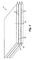
Figure .3 is a schematic perspective view illustrating another embodiment of the printhead assembly ofFigure 2 . -
Figure 4 is a schematic perspective view illustrating one embodiment of a portion of an outer layer of the printhead assembly ofFigure 2 . -
Figure 5 is a schematic cross-sectional view illustrating one embodiment of a portion of the printhead assembly ofFigure 2 . -
Figure 6 is a schematic plan view illustrating one embodiment of an inner layer of the printhead assembly ofFigure 2 . -
Figure 7 is a schematic plan view illustrating another embodiment of an inner layer of the printhead assembly ofFigure 2 . - In the following Detailed Description, reference is made to the accompanying drawings which form a part hereof, and in which is shown by way of illustration specific embodiments in which the invention may be practiced. In this regard, directional terminology, such as "top," "bottom," "front," "back," "leading," "trailing," etc., is used with reference to the orientation of the Figure(s) being described. Because components of embodiments of the present invention can be positioned in a number of different orientations, the directional terminology is used for purposes of illustration and is in no way limiting. It is to be understood that other embodiments may be utilized and structural or logical changes may be made without departing from the scope of the present invention. The following detailed description, therefore, is not to be taken in a limiting sense, and the scope of the present invention is defined by the appended claims.
-
Figure 1 illustrates one embodiment of aninkjet printing system 10 according to the present invention.Inkjet printing system 10 constitutes one embodiment of a fluid ejection system which includes a fluid ejection assembly, such as aprinthead assembly 12, and a fluid supply assembly, such as anink supply assembly 14. In the illustrated embodiment,inkjet printing system 10 also includes amounting assembly 16, amedia transport assembly 18, and anelectronic controller 20. -
Printhead assembly 12, as one embodiment of a fluid ejection assembly, is formed according to an embodiment of the present invention and ejects drops of ink, including one or more colored inks or UV readable inks, through a plurality of orifices ornozzles 13. While the following description refers to the ejection of ink fromprinthead assembly 12, it is understood that other liquids, fluids, or flowable materials, including clear fluid, may be ejected fromprinthead assembly 12. - In one embodiment, the drops are directed toward a medium, such as
print media 19, so as to print ontoprint media 19. Typically,nozzles 13 are arranged in one or more columns or arrays such that properly sequenced ejection of ink fromnozzles 13 causes, in one embodiment, characters, symbols, and/or other graphics or images to be printed uponprint media 19 asprinthead assembly 12 andprint media 19 are moved relative to each other. -
Print media 19 includes any type of suitable sheet material, such as paper, card stock, envelopes, labels, transparencies, Mylar, and the like. In one embodiment,print media 19 is a continuous form or continuousweb print media 19. As such,print media 19 may include a continuous roll of unprinted paper. -
Ink supply assembly 14, as one embodiment of a fluid supply assembly, supplies ink toprinthead assembly 12 and includes areservoir 15 for storing ink. As such, ink flows fromreservoir 15 toprinthead assembly 12. In one embodiment,ink supply assembly 14 andprinthead assembly 12 form a recirculating ink delivery system. As such, ink flows back toreservoir 15 fromprinthead assembly 12. In one embodiment,printhead assembly 12 andink supply assembly 14 are housed together in an inkjet or fluidjet cartridge or pen. In another embodiment,ink supply assembly 14 is separate fromprinthead assembly 12 and supplies ink toprinthead assembly 12 through an interface connection, such as a supply tube. -
Mounting assembly 16positions printhead assembly 12 relative tomedia transport assembly 18, andmedia transport assembly 18positions print media 19 relative toprinthead assembly 12. As such, aprint zone 17 within whichprinthead assembly 12 deposits ink drops is defined adjacent tonozzles 13 in an area betweenprinthead assembly 12 andprint media 19.Print media 19 is advanced throughprint zone 17 during printing bymedia transport assembly 18. - In one embodiment,
printhead assembly 12 is a scanning type printhead assembly, andmounting assembly 16 movesprinthead assembly 12 relative tomedia transport assembly 18 and printmedia 19 during printing of a swath onprint media 19. In another embodiment,printhead assembly 12 is a non-scanning type printhead assembly, and mountingassembly 16fixes printhead assembly 12 at a prescribed position relative tomedia transport assembly 18 during printing of a swath onprint media 19 asmedia transport assembly 18advances print media 19 past the prescribed position. -
Electronic controller 20 communicates withprinthead assembly 12,mounting assembly 16, andmedia transport assembly 18.Electronic controller 20 receivesdata 21 from a host system, such as a computer, and includes memory for temporarily storingdata 21. Typically,data 21 is sent toinkjet printing system 10 along an electronic, infrared, optical or other information transfer path.Data 21 represents, for example, a document and/or file to be printed. As such,data 21 forms a print job forinkjet printing system 10 and includes one or more print job commands and/or command parameters. - In one embodiment,
electronic controller 20 provides control ofprinthead assembly 12 including timing control for ejection of ink drops fromnozzles 13. As such,electronic controller 20 defines a pattern of ejected ink drops which form characters, symbols, and/or other graphics or images onprint media 19. Timing control and, therefore, the pattern of ejected ink drops, is determined by the print job commands and/or command parameters. In one embodiment, logic and drive circuitry forming a portion ofelectronic controller 20 is located onprinthead assembly 12. In another embodiment, logic and drive circuitry is located offprinthead assembly 12. -
Figure 2 illustrates one embodiment of a portion ofprinthead assembly 12. In one embodiment,printhead assembly 12 is a multi-layered assembly and includesouter layers inner layer 50.Outer layers side edge respective side Outer layers inner layer 50 such that sides 32 and 42 faceinner layer 50 and are adjacentinner layer 50. As such,inner layer 50 andouter layers axis 29. - As illustrated in the embodiment of
Figure 2 ,inner layer 50 andouter layers nozzles 13. Rows 60 ofnozzles 13 extend, for example, in a direction substantially perpendicular toaxis 29. As such, in one embodiment,axis 29 represents a print axis or axis of relative movement betweenprinthead assembly 12 andprint media 19. Thus, a length of rows 60 ofnozzles 13 establishes a swath height of a swath printed onprint media 19 byprinthead assembly 12. In one exemplary embodiment, rows 60 ofnozzles 13 span a distance less than approximately two inches. In another exemplary embodiment, rows 60 ofnozzles 13 span a distance greater than approximately two inches. - In one exemplary embodiment,
inner layer 50 andouter layers rows nozzles 13. More specifically,inner layer 50 andouter layer 30form row 61 ofnozzles 13 alongedge 34 ofouter layer 30, andinner layer 50 andouter layer 40form row 62 ofnozzles 13 alongedge 44 ofouter layer 40. As such, in one embodiment,rows nozzles 13 are spaced from and oriented substantially parallel to each other. - In one embodiment, as illustrated in
Figure 2 ,nozzles 13 ofrows nozzle 13 ofrow 61 is substantially aligned with onenozzle 13 ofrow 62 along a print line oriented substantially parallel toaxis 29. As such, the embodiment ofFigure 2 provides nozzle redundancy since fluid (or ink) can be ejected through multiple nozzles along a given print line. Thus, a defective or inoperative nozzle can be compensated for by another aligned nozzle. In addition, nozzle redundancy provides the ability to alternate nozzle activation amongst aligned nozzles. -
Figure 3 illustrates another embodiment of a portion ofprinthead assembly 12. Similar toprinthead assembly 12, printhead assembly 12' is a multi-layered assembly and includes outer layers 30' and 40', andinner layer 50. In addition, similar toouter layers inner layer 50. As such,inner layer 50 and outer layers 30' and 40' form two rows 61' and 62' ofnozzles 13. - As illustrated in the embodiment of
Figure 3 ,nozzles 13 of rows 61' and 62' are offset. More specifically, eachnozzle 13 of row 61' is staggered or offset from onenozzle 13 of row 62' along a print line oriented substantially parallel toaxis 29. As such, the embodiment ofFigure 3 provides increased resolution since the number of dots per inch (dpi) that can be printed along a line oriented substantially perpendicular toaxis 29 is increased. - In one embodiment, as illustrated in
Figure 4 ,outer layers 30 and 40 (only one of which is illustrated inFigure 4 and including outer layers 30' and 40') each include drop ejectingelements 70 andfluid pathways 80 formed onsides elements 70 andfluid pathways 80 are arranged such thatfluid pathways 80 communicate with and supply fluid (or ink) to drop ejectingelements 70. In one embodiment, drop ejectingelements 70 andfluid pathways 80 are arranged in substantially linear arrays onsides outer layers elements 70 andfluid pathways 80 ofouter layer 30 are formed on a single or monolithic layer, and all drop ejectingelements 70 andfluid pathways 80 ofouter layer 40 are formed on a single or monolithic layer. - In one embodiment, as described below, inner layer 50 (
Figure 2 ) has a fluid manifold or fluid passage defined therein which distributes fluid supplied, for example, byink supply assembly 14 tofluid pathways 80 and drop ejectingelements 70 formed onouter layers - In one embodiment,
fluid pathways 80 are defined bybarriers 82 formed onsides outer layers Figure 2 ) andfluid pathways 80 ofouter layer 30form row 61 ofnozzles 13 alongedge 34, and inner layer 50 (Figure 2 ) andfluid pathways 80 ofouter layer 40form row 62 ofnozzles 13 alongedge 44 whenouter layers inner layer 50. - As illustrated in the embodiment of
Figure 4 , eachfluid pathway 80 includes afluid inlet 84, afluid chamber 86, and afluid outlet 88 such thatfluid chamber 86 communicates withfluid inlet 84 andfluid outlet 88.Fluid inlet 84 communicates with a supply of fluid (or ink), as described below, and supplies fluid (or ink) tofluid chamber 86.Fluid outlet 88 communicates withfluid chamber 86 and, in one embodiment, forms a portion of arespective nozzle 13 whenouter layers inner layer 50. - In one embodiment, each drop ejecting
element 70 includes a firingresistor 72 formed withinfluid chamber 86 of arespective fluid pathway 80. Firingresistor 72 includes, for example, a heater resistor which, when energized, heats fluid withinfluid chamber 86 to produce a bubble withinfluid chamber 86 and generate a droplet of fluid which is ejected throughnozzle 13. As such, in one embodiment, arespective fluid chamber 86, firingresistor 72, andnozzle 13 form a drop generator of a respectivedrop ejecting element 70. - In one embodiment, during operation, fluid flows from
fluid inlet 84 tofluid chamber 86 where droplets of fluid are ejected fromfluid chamber 86 throughfluid outlet 88 and arespective nozzle 13 upon activation of arespective firing resistor 72. As such, droplets of fluid are ejected substantially parallel tosides outer layers printhead assembly 12 constitutes an edge or "side-shooter" design. - In one embodiment, as illustrated in
Figure 5 ,outer layers 30 and 40 (only one of which is illustrated inFigure 5 and including outer layers 30' and 40') each include asubstrate 90 and a thin-film structure 92 formed onsubstrate 90. As such, firingresistors 72 ofdrop ejecting elements 70 andbarriers 82 offluid pathways 80 are formed on thin-film structure 92. As described above,outer layers inner layer 50 to formfluid chamber 86 andnozzle 13 of a respectivedrop ejecting element 70. - In one embodiment,
inner layer 50 andsubstrate 90 ofouter layers inner layer 50 andouter layers inner layer 50 andouter layers inner layer 50 andsubstrate 90 ofouter layers - In one exemplary embodiment,
inner layer 50 andsubstrate 90 ofouter layers inner layer 50 andsubstrate 90 ofouter layers substrate 90. - In one embodiment, thin-
film structure 92 includesdrive circuitry 74 fordrop ejecting elements 70.Drive circuitry 74 provides, for example, power, ground, and logic fordrop ejecting elements 70 including, more specifically, firingresistors 72. - In one embodiment, thin-
film structure 92 includes one or more passivation or insulation layers formed, for example, of silicon dioxide, silicon carbide, silicon nitride, tantalum, poly-silicon glass, or other suitable material. In addition, thin-film structure 92 also includes one or more conductive layers formed, for example, by aluminum, gold, tantalum, tantalum-aluminum, or other metal or metal alloy. In one embodiment, thin-film structure 92 includes thin-film transistors which form a portion ofdrive circuitry 74 fordrop ejecting elements 70. - As illustrated in the embodiment of
Figure 5 ,barriers 82 offluid pathways 80 are formed on thin-film structure 92. In one embodiment,barriers 82 are formed of a non-conductive material compatible with the fluid (or ink) to be routed through and ejected fromprinthead assembly 12. Example materials suitable forbarriers 82 include a photo-imageable polymer and glass. The photo-imageable polymer may include a spun-on material, such as SU8, or a dry-film material, such as DuPont Vacrel®. - As illustrated in the embodiment of
Figure 5 ,outer layers 30 and 40 (including outer layers 30' and 40') are joined toinner layer 50 atbarriers 82. In one embodiment, whenbarriers 82 are formed of a photo-imageable polymer or glass,outer layers inner layer 50 by temperature and pressure. Other suitable joining or bonding techniques, however, can also be used to joinouter layers inner layer 50. - In one embodiment, as illustrated in
Figure 6 ,inner layer 50 includes a single inner layer 150. Single inner layer 150 has afirst side 151 and asecond side 152 oppositefirst side 151. In one embodiment,side 32 ofouter layer 30 is adjacentfirst side 151 andside 42 ofouter layer 40 is adjacentsecond side 152 whenouter layers inner layer 50. - In one embodiment, single inner layer 150 has a
fluid passage 154 defined therein.Fluid passage 154 includes, for example, anopening 155 which communicates withfirst side 151 andsecond side 152 of single inner layer 150 and extends between opposite ends of single inner layer 150. As such,fluid passage 154 distributes fluid through single inner layer 150 and tofluid pathways 80 ofouter layers outer layers - As illustrated in the embodiment of
Figure 6 , single inner layer 150 includes at least one fluid port 156. In one exemplary embodiment, single inner layer 150 includes fluid ports 157 and 158 each communicating withfluid passage 154. In one embodiment, fluid ports 157 and 158 form a fluid inlet and a fluid outlet forfluid passage 154. As such, fluid ports 157 and 158 communicate withink supply assembly 14 and enable circulation of fluid (or ink) betweenink supply assembly 14 andprinthead assembly 12. - In another embodiment, as illustrated in
Figure 7 ,inner layer 50 includes a plurality of inner layers 250. In one exemplary embodiment, inner layers 250 includeinner layers inner layer 253 is interposed betweeninner layers side 32 ofouter layer 30 is adjacentinner layer 251 andside 42 ofouter layer 40 is adjacentinner layer 252 whenouter layers - In one exemplary embodiment,
inner layers inner layers inner layers inner layers inner layers inner layers inner layers inner layers inner layers - In one embodiment, inner layers 250 have a fluid manifold or
fluid passage 254 defined therein.Fluid passage 254 includes, for example,openings 255 formed ininner layer 251,openings 256 formed ininner layer 252, andopenings 257 formed ininner layer 253.Openings openings 257 ofinner layer 253 communicate withopenings inner layers inner layer 253 is interposed betweeninner layers fluid passage 254 distributes fluid through inner layers 250 and tofluid pathways 80 ofouter layers outer layers - As illustrated in the embodiment of
Figure 7 , inner layers 250 include at least onefluid port 258. In one exemplary embodiment, inner layers 250 includefluid ports inner layers fluid ports openings 257 ofinner layer 253 wheninner layer 253 is interposed betweeninner layers fluid ports fluid passage 254. As such,fluid ports ink supply assembly 14 and enable circulation of fluid (or ink) betweenink supply assembly 14 andprinthead assembly 12. - In one embodiment, by forming
drop ejecting elements 70 andfluid pathways 80 onouter layers outer layers inner layer 50, as described above,printhead assembly 12 can be formed of varying lengths. For example,printhead assembly 12 may span a nominal page width, or a width shorter or longer than nominal page width. In one exemplary embodiment,printhead assembly 12 is formed as a wide-array or page-wide array such thatrows nozzles 13 span a nominal page width. - Although specific embodiments have been illustrated and described herein, it will be appreciated by those of ordinary skill in the art that a variety of alternate and/or equivalent implementations may be substituted for the specific embodiments shown and described without departing from the scope of the present invention. This application is intended to cover any adaptations or variations of the specific embodiments discussed herein. Therefore, it is intended that this invention be limited only by the claims and the equivalents thereof.
Claims (14)
- A fluid ejection assembly, comprising:at least one inner layer (50, 150, 250) having a fluid passage (154, 254) defined therein; andfirst and second outer layers (30, 40) positioned on opposite sides of the at least one inner layer,the first and second outer layers each including a substrate (90) and a thin-film structure (92) formed on the substrate, and drop ejecting elements (70, 72) formed on the thin film structure, the thin film structure and the drop ejecting elements being on the side of the outer layer adjacent the at least one inner layer,
each outer layer defining fluid pathways (80) communicated with the respective drop ejecting elements of the layer,wherein the fluid pathways (80) of the first and second outer layers communicate with the fluid passage (154, 254) of the at least one inner layer 50, 150, 250), andwherein the at least one inner layer and the fluid pathways of the first outer layer form a first row (61) of nozzles (13), and the at least one inner layer and the fluid pathways of the second outer layer form a second row (62) of nozzles (13). - The fluid ejection assembly of claim 1, wherein the at least one inner layer includes a single inner layer (150) having a first side (151) and a second side (152) opposite the first side, wherein the first outer layer is adjacent the first side and the second outer layer is adjacent the second side.
- The fluid ejection assembly of claim 1, wherein the at least one inner layer includes a first inner layer (251) adjacent the first outer layer, a second inner (252) layer adjacent the second outer layer, and a third inner layer (253) interposed between the first inner layer and the second inner layer.
- The fluid ejection assembly of claim 1, wherein the drop ejecting elements of the first outer layer are adapted to eject drops of fluid through the first row of nozzles substantially parallel to the said side of the first outer layer, and wherein the drop ejecting elements of the second outer layer are adapted to eject drops of fluid through the second row of nozzles substantially parallel to the said side of the second outer layer.
- The fluid ejection assembly of claim 1, wherein the first and second outer layers each have an edge (34, 44) contiguous with the said side thereof, wherein the first row of nozzles extend along the edge of the first outer layer and the second row of nozzles extend along the edge of the second outer layer.
- The fluid ejection assembly of claim 1, wherein each of the fluid pathways of the first and second outer layers include a fluid inlet (84), a fluid chamber (86) communicated with the fluid inlet, and a fluid outlet (88) communicated with the fluid chamber, and wherein the drop ejecting elements (70) are formed within respective fluid chambers of respective ones of the fluid pathways.
- The fluid ejection assembly of claim 1, wherein the substrate of each of the first and second outer layers includes a non-conductive material, wherein the non-conductive material includes one of glass, a ceramic material, a carbon composite material, and an oxide formed on one of a metal and a metal matrix composite material.
- The fluid ejection assembly of claim 1, wherein the thin -film structure includes drive circuitry (74) of the drop ejecting elements, wherein the drive circuitry includes thin -film transistors.
- The fluid ejection assembly of claim 1, wherein the first and second outer layers each include barriers (82) formed between the fluid pathways, wherein the barriers are formed on the thin -film structure of the first and second outer layers and are formed of one of a photo-imageable polymer and glass.
- The fluid ejection assembly of any preceding claim, wherein the drop ejecting elements are firing resistors.
- A method of forming a fluid ejection assembly, the method comprising:defining a fluid passage (154, 254) in at least one inner layer (50, 150, 250);forming first and second outer layers including forming a thin film structure (92) on a substrate of each of the first and second layers, and forming drop ejecting elements (70) on a side (32, 42) of the thin film structure of first and second outer layers (30, 40);forming fluid pathways (80) on the said side of each of the first and second outer layers, including communicating the fluid pathways with the drop ejecting elements; andpositioning the first and second outer layers on opposite sides of the at least one inner layer with the said side of each outer layer adjacent the inner layer, including communicating the fluid pathways of the first and second outer layers with the fluid passage of the at least one inner layer, andforming a first row (61) of nozzles (13) with the at least one inner layer and the fluid pathways of the first outer layer and forming a second row (62) of nozzles (13) with the at least one inner layer and the fluid pathways of the second outer layer.
- A method according to claim 11 further comprising forming a drive circuit in the thin film structure for the drop ejecting elements, the drive circuit includes thin film transistors.
- A method according to claim 11 or 12, wherein the drop ejecting elements are firing resistors.
- A method of operating the fluid ejection assembly of any one of claims 1-10, the method comprising:distributing fluid to the fluid pathways (80) through the fluid passage (154, 254) defined in the at least one inner layer (50); andactivating the drop ejecting elements formed on the thin-film structure (92) therebyejecting drops of the fluid through the first row (61) of nozzles and through the second row (62) of nozzles. (13).
Applications Claiming Priority (2)
| Application Number | Priority Date | Filing Date | Title |
|---|---|---|---|
| US10/613,471 US6890067B2 (en) | 2003-07-03 | 2003-07-03 | Fluid ejection assembly |
| PCT/US2004/020677 WO2005007412A1 (en) | 2003-07-03 | 2004-06-25 | Fluid ejection assembly |
Publications (2)
| Publication Number | Publication Date |
|---|---|
| EP1644197A1 EP1644197A1 (en) | 2006-04-12 |
| EP1644197B1 true EP1644197B1 (en) | 2011-03-09 |
Family
ID=33552701
Family Applications (1)
| Application Number | Title | Priority Date | Filing Date |
|---|---|---|---|
| EP04756240A Expired - Fee Related EP1644197B1 (en) | 2003-07-03 | 2004-06-25 | Fluid ejection assembly |
Country Status (9)
| Country | Link |
|---|---|
| US (1) | US6890067B2 (en) |
| EP (1) | EP1644197B1 (en) |
| JP (1) | JP2007527332A (en) |
| CN (1) | CN100436139C (en) |
| AR (1) | AR044998A1 (en) |
| CL (1) | CL2004000953A1 (en) |
| DE (1) | DE602004031735D1 (en) |
| TW (1) | TWI296971B (en) |
| WO (1) | WO2005007412A1 (en) |
Families Citing this family (12)
| Publication number | Priority date | Publication date | Assignee | Title |
|---|---|---|---|---|
| US6890067B2 (en) | 2003-07-03 | 2005-05-10 | Hewlett-Packard Development Company, L.P. | Fluid ejection assembly |
| US20050206679A1 (en) * | 2003-07-03 | 2005-09-22 | Rio Rivas | Fluid ejection assembly |
| US7540593B2 (en) * | 2005-04-26 | 2009-06-02 | Hewlett-Packard Development Company, L.P. | Fluid ejection assembly |
| US7380914B2 (en) * | 2005-04-26 | 2008-06-03 | Hewlett-Packard Development Company, L.P. | Fluid ejection assembly |
| US20070171261A1 (en) * | 2006-01-24 | 2007-07-26 | Samsung Electronics Co., Ltd | Array inkjet printhead |
| WO2008113182A1 (en) | 2007-03-21 | 2008-09-25 | Angstrom Power Incorporated | Fluid manifold and method therefor |
| US8133629B2 (en) * | 2007-03-21 | 2012-03-13 | SOCIéTé BIC | Fluidic distribution system and related methods |
| US8679694B2 (en) * | 2007-03-21 | 2014-03-25 | Societe Bic | Fluidic control system and method of manufacture |
| US7938513B2 (en) * | 2008-04-11 | 2011-05-10 | Lexmark International, Inc. | Heater chips with silicon die bonded on silicon substrate and methods of fabricating the heater chips |
| US8459779B2 (en) * | 2008-04-11 | 2013-06-11 | Lexmark International, Inc. | Heater chips with silicon die bonded on silicon substrate, including offset wire bonding |
| US20100116423A1 (en) * | 2008-11-07 | 2010-05-13 | Zachary Justin Reitmeier | Micro-fluid ejection device and method for assembling a micro-fluid ejection device by wafer-to-wafer bonding |
| EP3160751B1 (en) * | 2014-06-30 | 2020-02-12 | Hewlett-Packard Development Company, L.P. | Fluid ejection structure |
Family Cites Families (51)
| Publication number | Priority date | Publication date | Assignee | Title |
|---|---|---|---|---|
| US4894464A (en) * | 1980-01-21 | 1990-01-16 | Pfizer Inc. | Branched amides of L-aspartyl-D-amino acid dipeptides |
| AT372651B (en) * | 1980-12-15 | 1983-11-10 | Philips Nv | INK-JET PRINT HEAD AND METHOD FOR PRODUCING SUCH INK-JET PRINT HEAD |
| JPS57102366A (en) * | 1980-12-18 | 1982-06-25 | Canon Inc | Ink jet head |
| EP0067653A3 (en) * | 1981-06-13 | 1983-11-09 | Konica Corporation | Printing head for ink jet printer |
| US4611219A (en) * | 1981-12-29 | 1986-09-09 | Canon Kabushiki Kaisha | Liquid-jetting head |
| EP0087653B1 (en) | 1982-02-25 | 1985-12-11 | BOA A.G. Luzern | Transducing and compensating device for angle variations in pipelines |
| US4438191A (en) * | 1982-11-23 | 1984-03-20 | Hewlett-Packard Company | Monolithic ink jet print head |
| US4646110A (en) * | 1982-12-29 | 1987-02-24 | Canon Kabushiki Kaisha | Liquid injection recording apparatus |
| JPH0624855B2 (en) * | 1983-04-20 | 1994-04-06 | キヤノン株式会社 | Liquid jet recording head |
| JPH0613219B2 (en) * | 1983-04-30 | 1994-02-23 | キヤノン株式会社 | Inkjet head |
| JPH062416B2 (en) * | 1984-01-30 | 1994-01-12 | キヤノン株式会社 | Liquid jet recording head manufacturing method |
| US4730197A (en) * | 1985-11-06 | 1988-03-08 | Pitney Bowes Inc. | Impulse ink jet system |
| US4680595A (en) * | 1985-11-06 | 1987-07-14 | Pitney Bowes Inc. | Impulse ink jet print head and method of making same |
| US4965594A (en) * | 1986-02-28 | 1990-10-23 | Canon Kabushiki Kaisha | Liquid jet recording head with laminated heat resistive layers on a support member |
| US4894664A (en) * | 1986-04-28 | 1990-01-16 | Hewlett-Packard Company | Monolithic thermal ink jet printhead with integral nozzle and ink feed |
| US4695854A (en) * | 1986-07-30 | 1987-09-22 | Pitney Bowes Inc. | External manifold for ink jet array |
| US4897668A (en) * | 1987-03-02 | 1990-01-30 | Kabushiki Kaisha Toshiba | Apparatus for transferring ink from ink ribbon to a recording medium by applying heat to the medium, thereby recording data on the medium |
| US4823149A (en) * | 1987-03-09 | 1989-04-18 | Dataproducts Corporation | Ink jet apparatus employing plate-like structure |
| US5068674A (en) * | 1988-06-07 | 1991-11-26 | Canon Kabushiki Kaisha | Liquid jet recording head stabilization |
| DE68920634T2 (en) * | 1988-06-07 | 1995-05-24 | Canon Kk | Liquid jet recording head and recording device provided with this head. |
| JP2849109B2 (en) * | 1989-03-01 | 1999-01-20 | キヤノン株式会社 | Method of manufacturing liquid jet recording head and liquid jet recording head manufactured by the method |
| NL8903025A (en) * | 1989-12-08 | 1991-07-01 | Oce Nederland Bv | STACKABLE DROP GENERATOR FOR AN INK-JET PRINTER. |
| US5469199A (en) * | 1990-08-16 | 1995-11-21 | Hewlett-Packard Company | Wide inkjet printhead |
| US5132707A (en) * | 1990-12-24 | 1992-07-21 | Xerox Corporation | Ink jet printhead |
| US5604519A (en) * | 1992-04-02 | 1997-02-18 | Hewlett-Packard Company | Inkjet printhead architecture for high frequency operation |
| DE4225799A1 (en) * | 1992-07-31 | 1994-02-03 | Francotyp Postalia Gmbh | Inkjet printhead and process for its manufacture |
| US5825382A (en) * | 1992-07-31 | 1998-10-20 | Francotyp-Postalia Ag & Co. | Edge-shooter ink jet print head and method for its manufacture |
| JP3143549B2 (en) * | 1993-09-08 | 2001-03-07 | キヤノン株式会社 | Substrate for thermal recording head, inkjet recording head using the substrate, inkjet cartridge, inkjet recording apparatus, and method of driving recording head |
| DE4336416A1 (en) * | 1993-10-19 | 1995-08-24 | Francotyp Postalia Gmbh | Face shooter ink jet printhead and process for its manufacture |
| JPH07137270A (en) * | 1993-11-16 | 1995-05-30 | Canon Inc | Ink jet recorder |
| SG64335A1 (en) * | 1993-12-28 | 1999-04-27 | Seiko Epson Corp | Ink jet recording head |
| US5565900A (en) * | 1994-02-04 | 1996-10-15 | Hewlett-Packard Company | Unit print head assembly for ink-jet printing |
| DE4424771C1 (en) * | 1994-07-05 | 1995-11-23 | Francotyp Postalia Gmbh | Ink printhead made up of individual ink printing modules |
| DE59509149D1 (en) * | 1994-08-03 | 2001-05-10 | Francotyp Postalia Gmbh | Arrangement for plate-shaped piezo actuators and method for their production |
| US5748214A (en) * | 1994-08-04 | 1998-05-05 | Seiko Epson Corporation | Ink jet recording head |
| JP3196811B2 (en) * | 1994-10-17 | 2001-08-06 | セイコーエプソン株式会社 | Laminated ink jet recording head and method of manufacturing the same |
| US6135586A (en) * | 1995-10-31 | 2000-10-24 | Hewlett-Packard Company | Large area inkjet printhead |
| US6155674A (en) * | 1997-03-04 | 2000-12-05 | Hewlett-Packard Company | Structure to effect adhesion between substrate and ink barrier in ink jet printhead |
| US6209991B1 (en) * | 1997-03-04 | 2001-04-03 | Hewlett-Packard Company | Transition metal carbide films for applications in ink jet printheads |
| AUPO794697A0 (en) * | 1997-07-15 | 1997-08-07 | Silverbrook Research Pty Ltd | A device (MEMS10) |
| US6286939B1 (en) * | 1997-09-26 | 2001-09-11 | Hewlett-Packard Company | Method of treating a metal surface to increase polymer adhesion |
| US6024440A (en) * | 1998-01-08 | 2000-02-15 | Lexmark International, Inc. | Nozzle array for printhead |
| US5969736A (en) * | 1998-07-14 | 1999-10-19 | Hewlett-Packard Company | Passive pressure regulator for setting the pressure of a liquid to a predetermined pressure differential below a reference pressure |
| US6328428B1 (en) * | 1999-04-22 | 2001-12-11 | Hewlett-Packard Company | Ink-jet printhead and method of producing same |
| JP2001001522A (en) * | 1999-06-23 | 2001-01-09 | Fuji Xerox Co Ltd | Ink jet recording head |
| KR20010045298A (en) * | 1999-11-04 | 2001-06-05 | 윤종용 | Thermal-compress type fluid jetting apparatus using ink |
| US6652053B2 (en) | 2000-02-18 | 2003-11-25 | Canon Kabushiki Kaisha | Substrate for ink-jet printing head, ink-jet printing head, ink-jet cartridge, ink-jet printing apparatus, and method for detecting ink in ink-jet printing head |
| US6409323B1 (en) * | 2000-05-23 | 2002-06-25 | Silverbrook Research Pty Ltd | Laminated ink distribution assembly for a printer |
| US6281912B1 (en) * | 2000-05-23 | 2001-08-28 | Silverbrook Research Pty Ltd | Air supply arrangement for a printer |
| US6478404B2 (en) * | 2001-01-30 | 2002-11-12 | Hewlett-Packard Company | Ink jet printhead |
| US6890067B2 (en) | 2003-07-03 | 2005-05-10 | Hewlett-Packard Development Company, L.P. | Fluid ejection assembly |
-
2003
- 2003-07-03 US US10/613,471 patent/US6890067B2/en not_active Expired - Lifetime
-
2004
- 2004-03-26 TW TW093108367A patent/TWI296971B/en not_active IP Right Cessation
- 2004-05-04 CL CL200400953A patent/CL2004000953A1/en unknown
- 2004-06-25 DE DE602004031735T patent/DE602004031735D1/en active Active
- 2004-06-25 JP JP2006518699A patent/JP2007527332A/en active Pending
- 2004-06-25 WO PCT/US2004/020677 patent/WO2005007412A1/en active Search and Examination
- 2004-06-25 EP EP04756240A patent/EP1644197B1/en not_active Expired - Fee Related
- 2004-06-25 CN CNB2004800254229A patent/CN100436139C/en not_active Expired - Fee Related
- 2004-07-02 AR ARP040102339A patent/AR044998A1/en unknown
Also Published As
| Publication number | Publication date |
|---|---|
| TW200513391A (en) | 2005-04-16 |
| WO2005007412A1 (en) | 2005-01-27 |
| DE602004031735D1 (en) | 2011-04-21 |
| CL2004000953A1 (en) | 2005-04-15 |
| US6890067B2 (en) | 2005-05-10 |
| TWI296971B (en) | 2008-05-21 |
| JP2007527332A (en) | 2007-09-27 |
| CN1845824A (en) | 2006-10-11 |
| US20050001886A1 (en) | 2005-01-06 |
| EP1644197A1 (en) | 2006-04-12 |
| CN100436139C (en) | 2008-11-26 |
| AR044998A1 (en) | 2005-10-12 |
Similar Documents
| Publication | Publication Date | Title |
|---|---|---|
| EP2828081B1 (en) | Fluid ejection device with particle tolerant thin-film extension | |
| US6880926B2 (en) | Circulation through compound slots | |
| EP1644197B1 (en) | Fluid ejection assembly | |
| TWI568597B (en) | Fluid ejection device with ink feedhole bridge | |
| EP2158088B1 (en) | Fluid manifold for fluid ejection device | |
| EP1874545B1 (en) | Fluid ejection assembly | |
| EP1874544B1 (en) | Fluid ejection assembly | |
| US20050206679A1 (en) | Fluid ejection assembly | |
| US11155082B2 (en) | Fluid ejection die |
Legal Events
| Date | Code | Title | Description |
|---|---|---|---|
| PUAI | Public reference made under article 153(3) epc to a published international application that has entered the european phase |
Free format text: ORIGINAL CODE: 0009012 |
|
| 17P | Request for examination filed |
Effective date: 20060131 |
|
| AK | Designated contracting states |
Kind code of ref document: A1 Designated state(s): DE FR GB |
|
| DAX | Request for extension of the european patent (deleted) | ||
| RBV | Designated contracting states (corrected) |
Designated state(s): DE FR GB |
|
| RIN1 | Information on inventor provided before grant (corrected) |
Inventor name: DIEST, KENNETH Inventor name: LEBRON, HECTOR Inventor name: HOCK, SCOTT W. Inventor name: CRIVELLI, PAUL |
|
| 17Q | First examination report despatched |
Effective date: 20090703 |
|
| GRAP | Despatch of communication of intention to grant a patent |
Free format text: ORIGINAL CODE: EPIDOSNIGR1 |
|
| GRAS | Grant fee paid |
Free format text: ORIGINAL CODE: EPIDOSNIGR3 |
|
| GRAA | (expected) grant |
Free format text: ORIGINAL CODE: 0009210 |
|
| AK | Designated contracting states |
Kind code of ref document: B1 Designated state(s): DE FR GB |
|
| REG | Reference to a national code |
Ref country code: GB Ref legal event code: FG4D |
|
| REF | Corresponds to: |
Ref document number: 602004031735 Country of ref document: DE Date of ref document: 20110421 Kind code of ref document: P |
|
| REG | Reference to a national code |
Ref country code: DE Ref legal event code: R096 Ref document number: 602004031735 Country of ref document: DE Effective date: 20110421 |
|
| PLBE | No opposition filed within time limit |
Free format text: ORIGINAL CODE: 0009261 |
|
| STAA | Information on the status of an ep patent application or granted ep patent |
Free format text: STATUS: NO OPPOSITION FILED WITHIN TIME LIMIT |
|
| 26N | No opposition filed |
Effective date: 20111212 |
|
| REG | Reference to a national code |
Ref country code: DE Ref legal event code: R097 Ref document number: 602004031735 Country of ref document: DE Effective date: 20111212 |
|
| REG | Reference to a national code |
Ref country code: FR Ref legal event code: PLFP Year of fee payment: 13 |
|
| REG | Reference to a national code |
Ref country code: FR Ref legal event code: PLFP Year of fee payment: 14 |
|
| REG | Reference to a national code |
Ref country code: FR Ref legal event code: PLFP Year of fee payment: 15 |
|
| PGFP | Annual fee paid to national office [announced via postgrant information from national office to epo] |
Ref country code: DE Payment date: 20200519 Year of fee payment: 17 Ref country code: FR Payment date: 20200520 Year of fee payment: 17 |
|
| PGFP | Annual fee paid to national office [announced via postgrant information from national office to epo] |
Ref country code: GB Payment date: 20200525 Year of fee payment: 17 |
|
| REG | Reference to a national code |
Ref country code: DE Ref legal event code: R119 Ref document number: 602004031735 Country of ref document: DE |
|
| GBPC | Gb: european patent ceased through non-payment of renewal fee |
Effective date: 20210625 |
|
| PG25 | Lapsed in a contracting state [announced via postgrant information from national office to epo] |
Ref country code: GB Free format text: LAPSE BECAUSE OF NON-PAYMENT OF DUE FEES Effective date: 20210625 Ref country code: DE Free format text: LAPSE BECAUSE OF NON-PAYMENT OF DUE FEES Effective date: 20220101 |
|
| PG25 | Lapsed in a contracting state [announced via postgrant information from national office to epo] |
Ref country code: FR Free format text: LAPSE BECAUSE OF NON-PAYMENT OF DUE FEES Effective date: 20210630 |