EP1656899A1 - Glenoid instrumentation anti-migration threaded fastener - Google Patents
Glenoid instrumentation anti-migration threaded fastener Download PDFInfo
- Publication number
- EP1656899A1 EP1656899A1 EP05256460A EP05256460A EP1656899A1 EP 1656899 A1 EP1656899 A1 EP 1656899A1 EP 05256460 A EP05256460 A EP 05256460A EP 05256460 A EP05256460 A EP 05256460A EP 1656899 A1 EP1656899 A1 EP 1656899A1
- Authority
- EP
- European Patent Office
- Prior art keywords
- flank
- crest
- screw
- angle
- thread
- Prior art date
- Legal status (The legal status is an assumption and is not a legal conclusion. Google has not performed a legal analysis and makes no representation as to the accuracy of the status listed.)
- Granted
Links
Images


Classifications
-
- A—HUMAN NECESSITIES
- A61—MEDICAL OR VETERINARY SCIENCE; HYGIENE
- A61B—DIAGNOSIS; SURGERY; IDENTIFICATION
- A61B17/00—Surgical instruments, devices or methods, e.g. tourniquets
- A61B17/16—Bone cutting, breaking or removal means other than saws, e.g. Osteoclasts; Drills or chisels for bones; Trepans
- A61B17/17—Guides or aligning means for drills, mills, pins or wires
- A61B17/1725—Guides or aligning means for drills, mills, pins or wires for applying transverse screws or pins through intramedullary nails or pins
-
- A—HUMAN NECESSITIES
- A61—MEDICAL OR VETERINARY SCIENCE; HYGIENE
- A61B—DIAGNOSIS; SURGERY; IDENTIFICATION
- A61B17/00—Surgical instruments, devices or methods, e.g. tourniquets
- A61B17/16—Bone cutting, breaking or removal means other than saws, e.g. Osteoclasts; Drills or chisels for bones; Trepans
- A61B17/17—Guides or aligning means for drills, mills, pins or wires
- A61B17/1721—Guides or aligning means for drills, mills, pins or wires for applying pins along or parallel to the axis of the femoral neck
-
- A—HUMAN NECESSITIES
- A61—MEDICAL OR VETERINARY SCIENCE; HYGIENE
- A61B—DIAGNOSIS; SURGERY; IDENTIFICATION
- A61B17/00—Surgical instruments, devices or methods, e.g. tourniquets
- A61B17/56—Surgical instruments or methods for treatment of bones or joints; Devices specially adapted therefor
- A61B17/58—Surgical instruments or methods for treatment of bones or joints; Devices specially adapted therefor for osteosynthesis, e.g. bone plates, screws, setting implements or the like
- A61B17/68—Internal fixation devices, including fasteners and spinal fixators, even if a part thereof projects from the skin
- A61B17/74—Devices for the head or neck or trochanter of the femur
- A61B17/742—Devices for the head or neck or trochanter of the femur having one or more longitudinal elements oriented along or parallel to the axis of the neck
- A61B17/744—Devices for the head or neck or trochanter of the femur having one or more longitudinal elements oriented along or parallel to the axis of the neck the longitudinal elements coupled to an intramedullary nail
-
- A—HUMAN NECESSITIES
- A61—MEDICAL OR VETERINARY SCIENCE; HYGIENE
- A61B—DIAGNOSIS; SURGERY; IDENTIFICATION
- A61B17/00—Surgical instruments, devices or methods, e.g. tourniquets
- A61B17/56—Surgical instruments or methods for treatment of bones or joints; Devices specially adapted therefor
- A61B17/58—Surgical instruments or methods for treatment of bones or joints; Devices specially adapted therefor for osteosynthesis, e.g. bone plates, screws, setting implements or the like
- A61B17/68—Internal fixation devices, including fasteners and spinal fixators, even if a part thereof projects from the skin
- A61B17/84—Fasteners therefor or fasteners being internal fixation devices
- A61B17/86—Pins or screws or threaded wires; nuts therefor
- A61B17/8625—Shanks, i.e. parts contacting bone tissue
- A61B17/8635—Tips of screws
-
- A—HUMAN NECESSITIES
- A61—MEDICAL OR VETERINARY SCIENCE; HYGIENE
- A61B—DIAGNOSIS; SURGERY; IDENTIFICATION
- A61B17/00—Surgical instruments, devices or methods, e.g. tourniquets
- A61B17/56—Surgical instruments or methods for treatment of bones or joints; Devices specially adapted therefor
- A61B17/58—Surgical instruments or methods for treatment of bones or joints; Devices specially adapted therefor for osteosynthesis, e.g. bone plates, screws, setting implements or the like
- A61B17/68—Internal fixation devices, including fasteners and spinal fixators, even if a part thereof projects from the skin
- A61B17/84—Fasteners therefor or fasteners being internal fixation devices
- A61B17/86—Pins or screws or threaded wires; nuts therefor
- A61B17/864—Pins or screws or threaded wires; nuts therefor hollow, e.g. with socket or cannulated
Definitions
- the present invention relates generally to the field of orthopaedics, and more particularly, to a device for use in treating orthopaedic trauma.
- the skeletal system includes many long bones that extend from the human torso. These long bones include the femur, fibula, tibia, humerus, radius and ulna. These long bones are particularly exposed to trauma from accidents, and as such often are fractured during such trauma and may be subject to complex devastating fractures.
- the distal end or proximal portions of the long bone are fractured into several components and must be realigned.
- Mechanical devices commonly in the forms of pins, plates, screws, nails, wires and external devices are commonly used to attach fractured long bones.
- the pins, plates, wires, nails and screws are typically made of a durable material compatible to the human body, for example titanium, stainless steel or cobalt chromium.
- Fractures of the long bone are typically secured into position by at least one of three possible techniques.
- the first method is the use of intramedullary nails that are positioned in the intramedullary canal of those portions of the fractured bone.
- a second method of repairing fractured bones is the use of internal bone plates that are positioned under the soft tissue and on the exterior of the bone and bridges the fractured portion of the bone.
- Another method of securing fractured bones in position is the use of external fixators.
- These external fixators have at least two general categories. In one category the fixator is generally linear with a first portion of the fixator to connect to a first fracture segment of the bone and a second fracture segment of the fixator to connect to the second fracture segment of the bone. A first series of bone screws or pins are first connected to the fixator and then into the first portion of the bone. Then a second series of screws or pins are connected to the fixator and then to the second fracture segment of the bone, thereby securing the first portion fracture segment of the bone to the second portion of the bone.
- a second method of external fixation is through the use of a ring type fixator that uses a series of spaced-apart rings to secure the bone.
- a ring type fixator that uses a series of spaced-apart rings to secure the bone.
- an upper ring and a lower ring are spaced apart by rods.
- a plurality of wires is placed through the long bone and is connected on each end of the long bone by the ring. The wires are then tensioned much as a spoke in a bicycle are tightened, thereby providing for a rigid structure to support the first fracture segment portion of the bone.
- a plurality of wires are positioned through the second fracture segment of the bone and are secured to and tensioned by the lower ring to provide a rigid fixation of the second fracture segment of the bone bridging the fracture site.
- compression screw assemblies which include generally a compression plate having a barrel member, a lag screw and a compressing screw. The compression plate is secured to the exterior of the femur and the barrel member is inserted into a predrilled hole in the direction of the femoral head.
- the lag screw which has a threaded end and a smooth portion is inserted through the barrel member so that it extends across the break and into the femoral head.
- the threaded portion engages the femoral head.
- the compressing screw connects the lag screw to the plate. By adjusting the tension of the compressing screw the compression (reduction) of the fracture can be adjusted.
- the smooth portion of the lag screw must be free to slide through the barrel member to permit the adjustment of the compression screw.
- Subtrochanteric and femoral shaft fractures have been treated with the help of intramedullary rods which are inserted into the marrow canal of the femur to immobilize the femur parts involved in fractures.
- a single angled cross-nail or locking screw is inserted through the femur and the proximal end of the intramedullary rod. In some varieties, one or two screws may also be inserted through the femoral shaft and through the distal end of the intramedullary rod.
- the standard intramedullary rods have been successfully employed in treating fractures in lower portions of the femoral shaft.
- Trochanteric nails for use in preparing femoral neck fractures utilize a screw in the form of, for example, a lag screw.
- the lag screws have several different problems in use that are generally related to the lag screw not remaining in the proper position with respect to intramedullary nail during the operating live of an implant.
- the lag screw may cut proximally through the femoral neck and head causing the neck and head to move out its operating position in cooperation with the acetabulum. Such a movement be render the patient non-ambulatory.
- Another issue that may occur with lag screws is medial migration of a lag screw through the femoral head and into the pelvic cavity.
- Yet another issue with an intramedullary nail lag screw is lateral migration or lateral pullout of the screw from the long bone.
- neck collapse Early after the implantation of the trochanteric nail, for example, at the first weight-bearing instance of the patient, the head of the femur may move distally due to a phenomenon known as neck collapse. If the lag screw does not capture enough cancellous bone in the femoral neck, the neck and head may move laterally causing the phenomenon known as neck collapse and creating a leg length and other issues for the patient.
- a prior art intramedullary nail assembly 1 is shown in position on femur 2.
- the intramedullary nail assembly 1 includes an intramedullary nail 3 that is positioned in the medullary canal 4 of the femur 2.
- a lag screw 5 is positioned through transverse opening 6 of the nail 3.
- the lag screw 5 is utilized to connect the head 7 and neck 8 to the remainder of the femur 2.
- fracture site 9 is full of weak osteoporotic bone.
- FIG. 3 the intramedullary nail assembly 1 of FIG. 1 is shown in the femur 2 having experienced a collapse of the femoral neck 8.
- the threads 10 of lag screw 5 are insufficient to prevent head 7 of the femur 2 to collapse with the neck 8 causing the head 7 to migrate laterally on the patient.
- the screw 5 may extend as shown in FIG. 3 pass the periphery 11 of the head 7 and impinge into the acetabulum 12 causing a major problem for the patient.
- FIG. 4 the prior art intramedullary nail assembly 1 is shown in position on a femur 2 showing medial migration of the lag screw 5 into a position where the lag screw has passed through the acetabulum 12 causing a serious problem for the patient.
- intramedullary nail assembly 1 is shown with threads 10 of the lag screw 5 having provided for cut-out of the threads 10 through the neck 8 and the head 7 of the femur 2 causing the head 7 to move distally with respect to the patient.
- the cut-out phenomenon causes a problem for the patient and causes the patient to no longer be ambulatory.
- Synthes offers a locking mechanism to prevent medial migration.
- To address the length for cutting proximally through the femoral neck and head on Synthes does not utilize threads and utilizes a fluted tip that is hammered into the body instead of threaded to the nail.
- Nephew and Richards on utilizes a flat in the lag screw shaft in order to use a keyed centered sleeve mechanism to prevent rotation.
- Smith and Nephew are utilizing a locking compression screw in the distal end of the lag screw.
- the keyed sleeve and compression screw increase operating room time.
- a trochanteric nail is available from Stryker Corporation under the trade mark Gamma which utilizes a set screw threaded down the cannulation in the nail and grooves in the shafts of the lag screw to address the issue of medial migration.
- the new thread design of the present invention addresses the problems of thread cut-out and also the issue of medial migration.
- an orthopaedic screw is provided with a single thread form.
- the thread form runs along the central longitudinal axis of the screw. Starting from the proximal end, the thread starts as a flat section horizontal to the central longitudinal axis. The flat turns into an angle section rising away from the central longitudinal axis toward the distal end of the screw at an angle between 1 and 98°.
- the angular surface changes into a flat surface rising up from the central longitudinal axis. This flat surface is perpendicular to the central longitudinal.
- the perpendicular flat surface then changes into another flat surface that is parallel to the central longitudinal axis continuing to move distally along the central longitudinal axis.
- the current flat surface changes into another flat surface which is perpendicular to the central longitudinal axis.
- This finally flat surface changes into another flat surface that is parallel to the central longitudinal axis and is co-linear to the first flat surface. This pattern is repeated over again given length diameter of the rod.
- an orthopaedic screw includes a shank defining an end and a periphery of the shank. A portion of the periphery defines a thread form.
- the thread form includes a first flank, a crest adjacent the first flank and a second flank spaced from the first flank and adjacent the crest.
- the crest and the first flank form a first angle between the crest and the first flank.
- the crest and the second flank form a second angle between the crest and the second flank. The first angle and the second angle are different from each other.
- an intramedullary nail assembly for use in a medullary canal of a long bone.
- the assembly includes a nail for positioning at least partially in the medullary canal.
- the nail includes an aperture through the nail.
- the assembly also includes a screw fittably positioned in the aperture of the nail.
- the screw has a shank defining an end and a periphery of the shank. A portion of the periphery defines a thread form.
- the thread form includes a first flank, a crest adjacent the first flank and a second flank spaced from the first flank and adjacent the crest.
- the crest and the first flank form a first angle between the crest and the first flank.
- the crest and the second flank form a second angle between the crest and the second flank. The first angle and the second angle are different from each other.
- an orthopaedic screw for positioning in an aperture of an intramedullary nail.
- the screw has a shank defining an end and a periphery of the shank. A portion of the periphery defines a thread form.
- the thread form includes a first flank, a crest adjacent the first flank and a second flank spaced from the first flank and adjacent the crest.
- the crest and the first flank form a first spatial relationship between each other.
- the crest and the second flank form a second spatial relationship between each other.
- the first spatial relationship and the second spatial relationship are asymetrical from each other.
- a method for performing trauma surgery on a long bone includes the steps of providing an intramedullary nail including an aperture therethrough and positioning the nail at least partially in the medullary canal.
- the method further includes the step of providing a screw having a shoulder and a shank defining first and second ends and a periphery thereof, a portion of the periphery defining a thread form, the thread form including a first flank, a crest adjacent the first flank and a second flank spaced from the first flank and adjacent the crest, the crest and the first flank forming a first angle therebetween, the crest and the second flank forming a second angle therebetween, the first angle and the second angle being different from each other.
- the method further includes the steps of positioning the screw in the aperture of the nail and advancing the screw until the shoulder is in intimate contact with the cortical wall of the long bone.
- an orthopaedic screw including a thread form having a first crest and a second flank.
- the second flank forms a right angle with the crest and the first flank includes two portions with the first portion of the first flank and crest forming a right angle therebetween.
- the crest and the first and second flanks thereby form a box shaped thread.
- This box shaped thread provides for a better bone purchase.
- the present invention provides for a lag screw with better bone purchase.
- an orthopaedic screw having a thread form.
- the thread form includes a first flank, a crest and a second flank.
- the second flank and the crest form a right angle therebetween and the first flank includes a first portion and a second portion.
- the first portion of the first flank and the crest form a right angle therebetween.
- the orthopaedic screw provides for a box shaped thread form. This box shaped thread form increase the thread peak surface area.
- the present invention provides for increased thread peak surface area.
- the orthopaedic screw includes a thread form having a first flank, a crest and a second flank.
- the second flank and the crest form a right angle
- the first flank includes a first portion and a second portion with a first portion and the crest forming a right angle therebetween.
- the right angle between the first portion of the first flank and the crest reduces the ability of the orthopaedic screw of the present invention to cut or to migrate medially.
- the present invention provides for a slower migration rate for the orthopaedic screw.
- an orthopaedic screw is provided with a thread form having a first flank, a crest, and a second flank.
- the second flank and the crest form a right angle and the first flank includes a first portion and a second portion.
- the first portion of the first flank and the crest form a right angle therebetween.
- the crest, as well as the right angled flanks provide for a lack of a cutting edge or surface to provide for the magnitude of cut-out normally experienced in an orthopaedic lag screw.
- the present invention provides for reduced cyclic cut-out.
- an orthopaedic screw including a thread form having a flank, a crest and a second flank spaced from the first flank.
- the second flank and the crest form a right angle and the first flank includes a first portion and a second portion.
- the first portion of the first flank and the crest form a right angle therebetween.
- the right angle between the first portion of the first flank and the crest provide for a reduced or less easily rotated cutting edge for the orthopaedic screw.
- the present invention provides for a higher torque to initiate the rotation of the orthopaedic screw.
- an orthopaedic screw including a thread form having a first flank, a crest, and a second flank.
- the second flank and the crest form a right angle therebetween and the first flank includes a first potion and a second portion.
- the first portion of the first flank and the crest form a right angle therebetween.
- the somewhat sizable crest of the thread form of the present invention as well as the perpendicular orientation of the first portion of the first flank with respect to the crest and the perpendicular orientation cut-out second flank with respect to the crest results provide no cutting edge and require that the cancellous bone is compressed rather than cut so that the static cut-out is greatly reduced.
- the present invention provides for lower or reduced static cut-out.
- an orthopaedic screw including a thread form having a crest and a first flank and a second flank.
- the second flank and the crest form a right angle therebetween.
- the second flank is adjacent to the end of the screw when pullout of the orthopaedic screw is attempted.
- the second flank of the screw requires the cancellous bone to be compressed and does not permit the cancellous bone to be cut.
- the present invention provides for a higher pullout force when utilizing the orthopaedic screw of the present invention.
- the implants provided by the present invention can be used in a method for performing trauma surgery on a long bone, comprising the steps of:
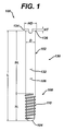
- FIGS. 1 and 8-11 show an orthopaedic screw 100 which includes a shank 102, which defines an end 104 and a periphery 106. A portion 108 of the periphery 106 defines a thread form 110.
- the thread form 110 includes a first flank 112 and a crest 114 adjacent the first flank 112.
- the thread form 110 also includes a second flank 116 spaced from the first flank 112 and adjacent crest 114.
- the crest 114 and the first flank 112 form a first angle ⁇ therebetween.
- the crest 114 and the second flank 160 form a second angle P therebetween.
- the first angle ⁇ and the second angle P are different from each other.
- the shank 102 defines a longitudinal axis 118 of the shank 102.
- the crest 114 as shown in FIG. 10, may be parallel to the longitudinal axis 118.
- the first angle ⁇ may be acute or less than 90°.
- the second angle ⁇ may as shown in FIG. 10, form a right angle or as shown in FIG. 10, the angle P may be, for example, 90°.
- the periphery 106 of the shank 102 may further define a second tooth form 120 spaced from the first tooth form 110.
- the periphery 106 may further define a root 122 positioned between the first tooth form 110 and the second tooth form 120.
- the periphery 106 of the shank 102 may include additional tooth forms in addition to the first tooth form 110 and the second tooth form 120.
- the periphery 106 of the shank 102 may include a third tooth form 124, a fourth tooth form 126, and a fifth tooth form 128.
- other tooth forms not shown in FIG. 10, may be used.
- each of the tooth forms 110, 120, 124, 126, and 128 may have identical shapes. It should be appreciated that in the alternative, the tooth forms may vary somewhat.
- periphery 106 of the shank 102 includes a second portion 130.
- the second portion 130 of the periphery 106 of the shank 102 as shown in FIG. 1, may define a smooth surface 132.
- the periphery 106 of the shank 102 may be generally cylindrical and may for example, be defined by a diameter, for example, D.
- the orthopaedic screw 100 of the present invention may further include a head 134.
- the head 134 may be in the form of, for example, a lip or a collar.
- the head 134 may extend from the shank 102 of the screw 100 and as shown in FIG. 1, may extend from a second end 136 of the shank 102 opposed to the first mentioned end 104.
- the thread form 110 may extend helically around the periphery 106 of the shank 102 for at least two revolutions.
- the thread form 110 may extend helically around the periphery shank 102 for several revolutions.
- the screw 100 may as shown in FIG. 1 include a total of, for example, around eight thread forms.
- the screw 100 as shown in FIG. 1, is generally cylindrical being defined by diameter D and an overall length L.
- the shank 102 of the screw 100 includes the first portion 108, which includes the thread form 110 and the second portion 130 having the smooth surface 132.
- the overall length L of the diameter D is divided into a thread length TL and a smooth length SL.
- the thread length TL defines the first portion 108 and the smooth length SL defines the second portion 130.
- the thread length TL may, for example, be a portion of, for example, 20% to 40% of the overall length L of the shank 102.
- the smooth length SL is preferably of sufficient length such that compression of the fracture can occur when the screw 100 is positioned in an intramedullary nail.
- the head 134 nay be defined a head thickness HT and a head diameter HD.
- the head thickness HT and head diameter HD are chosen to be sufficient to provide for a stop medially for the screw 100 when used in an intramedullary nail.
- a first arcuate feature 136 may, as is shown in FIG. 11, connect the first flank 112 to the crest 114.
- the arcuate feature 136 may, for example, be in the form of a radius, for example, a radius R1.
- a second arcuate feature 138 may connect the second flank 116 to the crest 114.
- the second arcuate feature 138 like the first arcuate feature 136 may be in the form of, for example, a radius, for example, radius R2.
- R1 and R2 may be chosen to be large enough to reduce the cutting ability of the thread form 110. By reducing the ability of the thread form 110 to cut cancellous bone, the pull-out forces, the ability to medially migrate, and the cut-out phenomenon of the screw 100 are optimized.
- the radii R1 and R2 may, for example, be around 1 to 4mm.
- the thread 110 may include a third arcuate feature 140 positioned between root 122 and the second flank 116.
- the third arcuate feature 140 may be in the form of a radius, for example radius R3.
- the thread form 110 may also include a fourth arcuate feature 142 positioned between root 122 and first flank 112.
- the fourth arcuate feature 142 may be in the form of, for example, a radius R4.
- the radii R3 and R4 may be chosen to minimize stress risers for the screw 100 and to optimize the thread cutting ability of the screw 100.
- the radii R3 and R4 may be, for example, 2 to 5 mm.
- first flank 112 may, it should be appreciated, be flat or linear, as shown in FIG. 11, the first flank may include a first portion 144 extending from the crest 114 and a second portion 146 extending from the first portion 144.
- the first portion 144 and the second portion 146 may, as is shown in FIG. 11, have a different orientation.
- the first portion 144 may form an angle ⁇ of, for example, 90° with the crest 114.
- the second portion 146 may form an obtuse angle ⁇ with the first portion 144.
- the obtuse angle may be approximately 140°.
- the first arcuate portion 144 and the second arcuate portion 146 may define an arcuate feature 148 therebetween.
- the arcuate feature 148 may be in the form of, for example, a radius R5.
- the radius R5 may be chosen to minimize stress risers and to provide for the proper thread cutting.
- the distance between adjacent thread forms, for example, first thread form 110 and second thread form 120 may be defined by a dimension, a pitch P.
- the pitch P may be chosen relative to other factors such as the diameter D of the screw 100.
- the dimension of the pitch P may be selected to provide for increasing thread pull-out forces and reducing medial migration incidents.
- the crest 114 and the root 122 define a thread depth TD.
- the thread depth TD is selected to optimize the work required to rotate the screw 100 through cancellous bone and to minimize problems with thread pull-out and medial migration.
- the first portion 114 defines a first portion height FPH.
- the first portion height FPH is selected as a portion of the thread depth TD to compromise between torque required to thread the screw 100 into cancellous bone and to minimize medial migration of the screw 100.
- the first portion height FPH is, for example, a percentage of the thread depth TD.
- the first portion height FPH may be, for example, 20 to 40% of the thread depth TD.
- the first portion height FPH may be for example, around 1 ⁇ 4 of the thread depth TD.
- the thread form 110 is chosen to optimize the strength of the thread form 110, the ability of the thread form 110 to cut threads and to avoid medial migration and to preserve the strength remaining in the portion of the cancellous bone between the adjacent thread forms 110.
- the thread form 110 defines a thread form cross-sectional area TCA bounded by, as shown in FIG. 11, the second flank 116, the crest 114, and the first portion 110 and the second portion 116 of the first flank 112. Between adjacent thread forms a thread spacing area TSA is formed between the first flank 112 of the first thread form 110 and the second flank of the second thread form 120.
- the relative size of the thread cross-sectional area TCA and the thread spacing area TSA is chosen to minimize medial migration while providing for sufficient thread pull-out force.
- the thread spacing area TSA establishes the area of cancellous bone that must be displaced by the screw 100 during pull-out.
- the ratio of the thread cross-sectional area to the thread spacing area may be, for example, from around 30% to around 50%.
- the thread cross-sectional may be around 40% of the total cross-sectional area including the thread cross-sectional area and the tooth spacing cross-sectional area.
- First portion 144 of the first flank 112 requires that the cancellous bone in the femur be condensed when advancing the screw 100 in the direction of arrow 150 toward end 104.
- the first portion 144 serves to limit medial migration of the screw 100 in the direction of arrow 150.
- the second flank 116 causes the cancellous bone in the femur to be compressed when the screw 100 is advanced in the direction of arrow 152 toward head 134.
- the second flank 116 serves to prevent or establish for the amount of pull-out required to move the screw 100 in the direction of arrow 152.
- each of the adjacent thread forms 110 have substantially the same shape. It should be appreciated however, to assist in the installing of the screw 100 into cancellous bone a chamfer 154 is formed on periphery 106 of the shank 102 of the screw 100.
- the chamfer 154 may, is as shown FIGS. 8-9 be defined by a chamfer angle ⁇ and by chamfer diameter CD.
- the chamfer diameter CD and chamfer angle ⁇ to provide for proper thread torque and to minimize medial migration.
- FIGS. 10A-1OI alternative thread forms are shown. These alternative thread forms are believed to be effective to reduce medial migration and cut-out of the lag screws.
- tooth form 110A of screw 100A is shown.
- the tooth form 100A includes a crest 114A from which first flank 112A extends at an angle ⁇ A.
- the second flank 116A extends from crest 114A at an angle ⁇ A that is obtuse.
- the angle ⁇ A is greater than 90°.
- the tooth form 110B includes a crest 114B.
- First flank 112B extends from crest 114B at angle ⁇ B.
- the first flank 112B includes a first portion 144B and a second portion 146B.
- the second portion 146B extend from first portion 144B at obtuse angle ⁇ B.
- the tooth form 110B further includes a second flank 116B extending from crest 114B at an angle ⁇ B.
- yet another tooth form is in the form of tooth form 110C for screw 100C.
- the tooth form 110C includes a crest 114C from which first flank 112C and second flank 116C extend.
- the first flank 112C and the second flank 116C are normal or perpendicular to the crest 114C and therefore parallel to each other.
- the angle BC and ⁇ C are thus 90°.
- the tooth form 110D includes a crest 114D that is arcuate.
- a first flank 112 D extends from the crest 114D at an angle ⁇ D and a second flank 116D extends perpendicularly from the crest 114D at angle BD.
- the tooth form 110E includes a crest a 114E from which first flank 112E and second flank 116E extend.
- the first flank 112E includes a first portion 144E formed, angle ⁇ E with crest 114E and a second portion 146E forming angle ⁇ E with first portion 144E.
- the second flank 116E extends perpendicularly or normally from the crest 114E.
- the tooth form 100F includes a crest 114F which is arcuate. Extending from the crest 114F are first flank 112F and second flank 116F. The first flank 112F and the second flank 116F are normal or perpendicular to the crest 114F and therefore parallel to each other. The angles F and ⁇ F are both 90°.
- the tooth form 110G is for use with screw 100G.
- the tooth form 110G includes a crest 114G from which first flank 112 and second flank 116 extend.
- the first flank 112G includes a first portion 144G and a second portion 146G.
- the second flank 146G includes a first portion 118G and a second portion 120G.
- the first flank 112G and the second flank 116G as shown in FIG. 10G are not symmetrical. Thus, angles ⁇ G and BG are different and angles ⁇ G and BBG are different.
- the tooth form 110H includes a crest 114H from which a first flank 112H and a second flank 116H extend.
- the first flank 112H includes a first portion 144H and a second portion 146H.
- the second flank 116H includes a first portion 118H and a second portion 120H.
- the tooth form 110H of FIG. 10H is different than the other tooth forms in that the first flank 112 and the second flank 116 are symmetrical about the crest 114H.
- Angles ⁇ H and BH are the same and angles ⁇ H and ⁇ H are the same.
- the tooth form 110I includes a crest 114I from which a first flank 112I and a second flank 116I extend.
- the first flank 112I includes a first portion 144I and a second portion 146I.
- the second flank 116I includes a first portion 118I and a second portion 120I.
- the portions 144, 146, 118, and 120 are shown in FIG. 10I are normal or perpendicular to the crest 114I or consequently are all parallel to each other. Angles ⁇ I, BI, ⁇ I and ⁇ I are all 90°.
- the screw 100 may include a central opening or cannula 156 positioned concentric with longitudinal axis 118 of the screw 100.
- the cannula 156 may be defined by a cannula diameter CD.
- the diameter CD is selected for fitting with a wire that may be used with the installation of the screw 100 into the cancellous bone of the femur 2.
- orthopaedic screw 100 is similar to the orthopaedic screw 100 of FIGS. 1 and 8-11 except that the screw 100 includes a shank 102 prime that is solid or not cannulated.
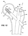
- trochanteric nail assembly 200 is shown as trochanteric nail assembly 200.
- the trochanteric or intramedullary nail assembly 200 is designed for use in a medullary canal for of a long bone 2.
- the nail assembly 200 includes a nail 202 for positioning for at least partially of the medullary canal 4.
- the nail 202 includes an aperture or opening 204 through the nail 202.
- the nail assembly 200 further includes a screw, for example, screw 100 of FIGS. 1 and 8-11.
- the screw 100 is fittably positioned in the aperture 204 of the nail 202.
- the screw 100 includes the shank 102 defining end 104 and periphery 106.
- a portion of the periphery 106 defines thread form 110.
- the thread form 110 includes first flank 112, crest 114 adjacent to the first flank 112, and second flank 116 spaced from the first flank 112 adjacent the crest 114.
- the crest 114 and the first flank 112 form a first angle therebetween.
- the crest 114 and the second flank form a second angle therebetween.
- the first angle and the second angle are different from each other.
- the orthopaedic screw 100 is utilized with nail 202 in the form of a trochanteric nail.
- the screw 100 may be used with an intramedullary nail, for example, a femoral nail, tibial nail, antegrade nail, retrograde nail, or a universal nail capable for use for various indications.
- the orthopaedic screw 100 is fitted into neck 8 and head 7 of the long bone 2.
- the long bone 2 may as is shown in FIG. 12 be, for example, a femur.
- Intramedullary nail 202 may be any suitable nail and may, as shown in FIG. 12, be canulated or define a longitudinal opening 206 extending the length of the nail 202.
- the intramedullary nail may also include a cap 208 threadably secured to the intramedullary nail 202 by external threads 210 formed on the cap which mate with internal threads 212 formed in the opening 206 of the intramedullary nail 202.
- the screw 100 as shown in FIG. 12 may include the head 134.
- the head 134 as is shown in FIG. 12, preferably rests against internal wall 14 of the cordical bone 16 of the long bone 2.
- the nail assembly 200 is shown installed on long bone 2 with the screw 100 advancing in the direction of arrow 214 or advancing medially. While such medial migration should be unlikely with the thread form 110 of the screw 100 of the present invention, it should be appreciated that the medial migration in the direction of arrow 214 will be physically limited by the seating of the head 134 against outer periphery 216 of the trochanteric nail 202.
- the anti-rotation screw 300 includes a shank 302 which as is shown in FIG. 14 and 15, is generally cylindrical.
- the shank 302 unlike the shank 102 of the screw 100 of FIG. 1 is not canulated.
- the screw 300 further includes a periphery 306 which defines a first portion 302 which includes a smooth surface 332 and a second portion 308 which defines a thread form 310.
- a head 334 extends from second end 336 of the shank 302 opposed to the first end 304 of the shank 302.
- the shank 302 may, as shown in FIGS. 14 and 15, have a diameter D2 and a length L2.
- the length L2 is divided through a thread-length TL2 in the first portion 308 and a smooth length SL2 in the second portion 330 of the shank 302.
- the thread-form 310 includes a crest 314 from which first flank 312 and second flank 316 extend.
- the first flank 312 is arcuate and, as is shown in FIG. 16, is defined by a radius RR extending from origin 360.
- the second flank 316 forms an angle b2 with respect to the crest 314.
- the angle b2 may, as shown in FIG. 16, be approximately 90°.
- the thread-form 310 may further define a root 322.
- the root 322 and the crest 314 define a thread-depth TD-2.
- Adjacent thread-forms 310 define a thread-pitch P2.
- the pitch P2 and the thread-depth TD2 are selected to provide for proper insertion torque and to maximize the required pull-out force and to minimize medial migration.
- the screw 300 further includes a chamfer 352 extending from first end 304 of the screw 300.
- the chamfer 352 may be defined by chamfer diameter CD2 and chamfer angle ⁇ 2. Angle 02 and the diameter CD2 are chosen to provide for reasonable insertion torque and to minimize medial migration.
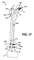
- FIGS. 17-20 another embodiment of the present invention is shown as intramedullary nail assembly or trochanteric nail assembly 400.
- the nail assembly 400 is similar to the nail assembly 200 of FIGS. 12 and 13, except that the nail assembly 400 further includes anti-rotation screw 300 in addition to the lag screw 100.
- the nail assembly 400 includes the lag screw 100, the anti-rotation screw 300, and a trochanteric nail 402.
- the trochanteric nail 402 is fitted into intramedullary canal 4 of the long bone 2.
- the nail 402 includes a first opening 404 for slidable passage of the lag screw 100 as well as a parallel spaced apart second opening 440 for slidable fitting with the anti-rotation screw 300.
- Nail 302 may also include a longitudinal cannula or opening 406.
- the nail 402 may further include a first distal opening 442 for receiving a first cortical screw 444 for engagement with the cortical bone 16 of the long bone 2.
- the first cortical screw 444 may be defined by a length CL2 and a diameter CD 1.
- the nail 402 may use a solitary cortical screw 444 but may, as is shown in FIG. 17, include a second cortical screw 446 which is fitted to second distal transverse opening 448 formed in the nail 402.
- the second cortical screw 446 may be defined by a length CL2 and a diameter CD2.
- the second cortical screw 446 engages the cortical bone 16 of the long bone 2.
- the lag screw 100 and the anti-rotation screw 300 are adapted to extend into neck 8 and head 7 of, for example and as shown in FIGS. 17 and 18, a long bone 2 in the form of a femur.
- the nail assembly 400 of FIGS. 17 to 20 is adapted for a inter-trochanteric fracture 18 extending from, for example, the lesser trochanter 20 to the greater trochanter 22.
- the lag screw 100 is positioned in the nail 402 such that head 134 of the lag screw 100 is seated against periphery 14 of the cortical bone 16 of the femur 2.
- the anti-rotation screw 300 is positioned in the nail 302 such that the head 334 of the anti-rotation screw 300 seats against periphery 14 of the cortical bone 16 of the femur 2.
- the first portion or threaded portion 108 of the lag screw 100 and the first portion or threaded portion 308 of the anti-rotation screw 300 are shown positioned in cancellous bone 26 of the head 7 of the femur 2.
- a wire 466 is shown extending from end 104 of the lag screw 100. The wire 466 slidably fits into the longitudinal opening or cannula 156 of the nail 100.
- trochanteric nail assembly or intramedullary nail assembly 500 yet another embodiment of the present invention is shown as trochanteric nail assembly or intramedullary nail assembly 500.
- the intramedullary nail assembly 500 is similar to the intramedullary nail assembly 400 of FIGS. 17-20, except that the intramedullary nail assembly 500 of FIGS. 21 and 22 includes a trochanteric nail 502 which is shorter than the trochanteric nail 402 of the nail assembly 400 of FIGS. 17-20.
- the nail assembly 500 includes nail 502 fitted into canal 4 of the femur 2.
- the nail 502 includes a first transverse opening 504 for slidable fitting with the lag screw 100.
- a second transverse opening 504 is positioned parallel in space from the first transverse opening 504.
- the second transverse opening 540 is adapted for slidably fitting of the anti-rotation screw 300.
- the nail 502 further includes a distal opening 542 for receiving distal screw 546 similar to distal screw 446 of the nail assembly 400 of FIGS. 17 to 20.
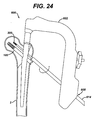
- the instrument 600 includes a body 602.
- the body 602 may be made of a radiolucent material, for example, a carbon fiber material, to assist in fluoroscopic procedures in installing the nail assembly 502.
- the body 602 may define a series of openings for guiding the screws through the femur 2 and into the nail 502.
- the instrument 600 may further include a connector or adapter 604 for cooperating with the nail 500 and for locking and orienting the nail 500 to the instrument 600.
- the adapter 604 may include features which cooperate with, for example, the end and the longitudinal opening of the nail 500.
- the instrument 600 as shown in FIG. 23, may include a first sheath 606 which matingly fits with first sheath opening 608 formed in the body 602 of the instrument 600. The first sheath 606 is utilized to guide an anti-rotation drill 610 into the femur 2.
- the instrument 600 may further include a second sheath 610 which is fitted through second opening 612 in the body 602 of the adapter 600. The second sheath 600 is used to guide the guide-wire 446 into the femur 2.
- the sheath 610 and the guide-wire 466 are used to guide the lag screw 300 into the nail 502 and into the femur 2.
- the instrument 600 further includes a third sheath 614 which is fitted into the first opening 608 in the body 602 of the instrument 600.
- the third sheath 614 is used to guide the anti-rotation screw 300 through the nail 502 and into the femur 2.
- the instrument 600 further includes a fourth sheath 616 which is fitted into third opening 618 formed in the body 602 of the instrument 600.
- the sheath 616 is utilized to guide a distal screw drill 620 into the femur 2 and the nail 502.
- the nail assembly 500 is shown positioned in femur 2 with the distal screw 546 and the lag screw 100 in position in the nail 502.
- a screwdriver 622 is shown installing the cap 550 onto the nail 502.
- the method 600 includes a first step of providing an intramedullary nail, including an aperture in the nail.
- the method 600 includes a second step 604 of positioning the nail at least partially in the medullary canal.
- the method 600 further includes a third step 606 of providing the screw having a shoulder and a shank defining first and second ends.
- the screw includes a periphery thereof with a portion of the periphery defining a thread-form.
- the thread-form includes a first flank, a crest adjacent to the first flank, and a second flank spaced from the first flank and adjacent the crest.
- the crest and the first flank form a first angle between each other.
- the crest and the second flank form a second angle between each other.
- the first angle and the second angle are different from each other.
- the method 600 further includes a fourth step 608 of positioning the screw in the aperture of the nail.
- the method 600 further includes a fifth step 610 of advancing the screw until the solider has into intimate contact with the cordical wall of the long bone.
Abstract
Description
- The present invention relates generally to the field of orthopaedics, and more particularly, to a device for use in treating orthopaedic trauma.
- The skeletal system includes many long bones that extend from the human torso. These long bones include the femur, fibula, tibia, humerus, radius and ulna. These long bones are particularly exposed to trauma from accidents, and as such often are fractured during such trauma and may be subject to complex devastating fractures.
- Automobile accidents, for instance, are a common cause of trauma to long bones. In particular, the femur and tibia frequently fracture when the area around the knee is subjected to a frontal automobile accident.
- Often the distal end or proximal portions of the long bone, for example the femur and the tibia, are fractured into several components and must be realigned. Mechanical devices, commonly in the forms of pins, plates, screws, nails, wires and external devices are commonly used to attach fractured long bones. The pins, plates, wires, nails and screws are typically made of a durable material compatible to the human body, for example titanium, stainless steel or cobalt chromium.
- Fractures of the long bone are typically secured into position by at least one of three possible techniques.
- The first method is the use of intramedullary nails that are positioned in the intramedullary canal of those portions of the fractured bone.
- A second method of repairing fractured bones is the use of internal bone plates that are positioned under the soft tissue and on the exterior of the bone and bridges the fractured portion of the bone.
- Another method of securing fractured bones in position is the use of external fixators. These external fixators have at least two general categories. In one category the fixator is generally linear with a first portion of the fixator to connect to a first fracture segment of the bone and a second fracture segment of the fixator to connect to the second fracture segment of the bone. A first series of bone screws or pins are first connected to the fixator and then into the first portion of the bone. Then a second series of screws or pins are connected to the fixator and then to the second fracture segment of the bone, thereby securing the first portion fracture segment of the bone to the second portion of the bone.
- A second method of external fixation is through the use of a ring type fixator that uses a series of spaced-apart rings to secure the bone. For example, an upper ring and a lower ring are spaced apart by rods. A plurality of wires is placed through the long bone and is connected on each end of the long bone by the ring. The wires are then tensioned much as a spoke in a bicycle are tightened, thereby providing for a rigid structure to support the first fracture segment portion of the bone. Similarly, a plurality of wires are positioned through the second fracture segment of the bone and are secured to and tensioned by the lower ring to provide a rigid fixation of the second fracture segment of the bone bridging the fracture site.
- There are a variety of devices used to treat femoral fractures. Fractures of the neck, head or intertrochanter of the femur have been successfully treated with a variety of compression screw assemblies which include generally a compression plate having a barrel member, a lag screw and a compressing screw. The compression plate is secured to the exterior of the femur and the barrel member is inserted into a predrilled hole in the direction of the femoral head.
- The lag screw, which has a threaded end and a smooth portion is inserted through the barrel member so that it extends across the break and into the femoral head. The threaded portion engages the femoral head. The compressing screw connects the lag screw to the plate. By adjusting the tension of the compressing screw the compression (reduction) of the fracture can be adjusted. The smooth portion of the lag screw must be free to slide through the barrel member to permit the adjustment of the compression screw.
- Subtrochanteric and femoral shaft fractures have been treated with the help of intramedullary rods which are inserted into the marrow canal of the femur to immobilize the femur parts involved in fractures. A single angled cross-nail or locking screw is inserted through the femur and the proximal end of the intramedullary rod. In some varieties, one or two screws may also be inserted through the femoral shaft and through the distal end of the intramedullary rod. The standard intramedullary rods have been successfully employed in treating fractures in lower portions of the femoral shaft.
- Trochanteric nails for use in preparing femoral neck fractures utilize a screw in the form of, for example, a lag screw. The lag screws have several different problems in use that are generally related to the lag screw not remaining in the proper position with respect to intramedullary nail during the operating live of an implant. For example, the lag screw may cut proximally through the femoral neck and head causing the neck and head to move out its operating position in cooperation with the acetabulum. Such a movement be render the patient non-ambulatory. Another issue that may occur with lag screws is medial migration of a lag screw through the femoral head and into the pelvic cavity. Yet another issue with an intramedullary nail lag screw is lateral migration or lateral pullout of the screw from the long bone.
- Yet another problem with lag screws in trochanteric nail applications is the problem of neck collapse. Early after the implantation of the trochanteric nail, for example, at the first weight-bearing instance of the patient, the head of the femur may move distally due to a phenomenon known as neck collapse. If the lag screw does not capture enough cancellous bone in the femoral neck, the neck and head may move laterally causing the phenomenon known as neck collapse and creating a leg length and other issues for the patient.
- Referring now to FIG. 2, a prior art intramedullary nail assembly 1 is shown in position on
femur 2. The intramedullary nail assembly 1 includes anintramedullary nail 3 that is positioned in the medullary canal 4 of thefemur 2. Alag screw 5 is positioned throughtransverse opening 6 of thenail 3. Thelag screw 5 is utilized to connect thehead 7 andneck 8 to the remainder of thefemur 2. As can be seen in FIG. 2,fracture site 9 is full of weak osteoporotic bone. - Referring now to FIG. 3, the intramedullary nail assembly 1 of FIG. 1 is shown in the
femur 2 having experienced a collapse of thefemoral neck 8. Thethreads 10 oflag screw 5 are insufficient to preventhead 7 of thefemur 2 to collapse with theneck 8 causing thehead 7 to migrate laterally on the patient. Thescrew 5 may extend as shown in FIG. 3 pass theperiphery 11 of thehead 7 and impinge into theacetabulum 12 causing a major problem for the patient. - Referring now to FIG. 4, the prior art intramedullary nail assembly 1 is shown in position on a
femur 2 showing medial migration of thelag screw 5 into a position where the lag screw has passed through theacetabulum 12 causing a serious problem for the patient. - Referring now to FIG. 5, intramedullary nail assembly 1 is shown with
threads 10 of thelag screw 5 having provided for cut-out of thethreads 10 through theneck 8 and thehead 7 of thefemur 2 causing thehead 7 to move distally with respect to the patient. The cut-out phenomenon, as shown in FIG. 5, causes a problem for the patient and causes the patient to no longer be ambulatory. - Attempts have been made to overcome the problem with medial migration. For example, Synthes offers a locking mechanism to prevent medial migration. To address the length for cutting proximally through the femoral neck and head on Synthes does not utilize threads and utilizes a fluted tip that is hammered into the body instead of threaded to the nail.
- To overcome problems with rotation of the lag screw in the intramedullary nail Smith, Nephew and Richards on utilizes a flat in the lag screw shaft in order to use a keyed centered sleeve mechanism to prevent rotation. To prevent migration, Smith and Nephew are utilizing a locking compression screw in the distal end of the lag screw. The keyed sleeve and compression screw increase operating room time.
- A trochanteric nail is available from Stryker Corporation under the trade mark Gamma which utilizes a set screw threaded down the cannulation in the nail and grooves in the shafts of the lag screw to address the issue of medial migration.
- The new thread design of the present invention addresses the problems of thread cut-out and also the issue of medial migration.
- According to the present invention, an orthopaedic screw is provided with a single thread form. The thread form runs along the central longitudinal axis of the screw. Starting from the proximal end, the thread starts as a flat section horizontal to the central longitudinal axis. The flat turns into an angle section rising away from the central longitudinal axis toward the distal end of the screw at an angle between 1 and 98°. The angular surface changes into a flat surface rising up from the central longitudinal axis. This flat surface is perpendicular to the central longitudinal.
- The perpendicular flat surface then changes into another flat surface that is parallel to the central longitudinal axis continuing to move distally along the central longitudinal axis. The current flat surface changes into another flat surface which is perpendicular to the central longitudinal axis. This finally flat surface changes into another flat surface that is parallel to the central longitudinal axis and is co-linear to the first flat surface. This pattern is repeated over again given length diameter of the rod.
- According to one embodiment of the present invention, there is provided an orthopaedic screw. The orthopaedic screw includes a shank defining an end and a periphery of the shank. A portion of the periphery defines a thread form. The thread form includes a first flank, a crest adjacent the first flank and a second flank spaced from the first flank and adjacent the crest. The crest and the first flank form a first angle between the crest and the first flank. The crest and the second flank form a second angle between the crest and the second flank. The first angle and the second angle are different from each other.
- According to another embodiment of the present invention there is provided an intramedullary nail assembly for use in a medullary canal of a long bone. The assembly includes a nail for positioning at least partially in the medullary canal. The nail includes an aperture through the nail. The assembly also includes a screw fittably positioned in the aperture of the nail. The screw has a shank defining an end and a periphery of the shank. A portion of the periphery defines a thread form. The thread form includes a first flank, a crest adjacent the first flank and a second flank spaced from the first flank and adjacent the crest. The crest and the first flank form a first angle between the crest and the first flank. The crest and the second flank form a second angle between the crest and the second flank. The first angle and the second angle are different from each other.
- According to yet another embodiment of the present invention there is provided an orthopaedic screw for positioning in an aperture of an intramedullary nail. The screw has a shank defining an end and a periphery of the shank. A portion of the periphery defines a thread form. The thread form includes a first flank, a crest adjacent the first flank and a second flank spaced from the first flank and adjacent the crest. The crest and the first flank form a first spatial relationship between each other. The crest and the second flank form a second spatial relationship between each other. The first spatial relationship and the second spatial relationship are asymetrical from each other.
- According to a further embodiment of the present invention, there is provided a method for performing trauma surgery on a long bone. The method includes the steps of providing an intramedullary nail including an aperture therethrough and positioning the nail at least partially in the medullary canal. The method further includes the step of providing a screw having a shoulder and a shank defining first and second ends and a periphery thereof, a portion of the periphery defining a thread form, the thread form including a first flank, a crest adjacent the first flank and a second flank spaced from the first flank and adjacent the crest, the crest and the first flank forming a first angle therebetween, the crest and the second flank forming a second angle therebetween, the first angle and the second angle being different from each other. The method further includes the steps of positioning the screw in the aperture of the nail and advancing the screw until the shoulder is in intimate contact with the cortical wall of the long bone.
- Technical advantages of the present invention include the ability to provide a lag screw with better bone purchase for use in a trochanteric nail assembly. For example, according to one aspect of the present invention, an orthopaedic screw is provided including a thread form having a first crest and a second flank. The second flank forms a right angle with the crest and the first flank includes two portions with the first portion of the first flank and crest forming a right angle therebetween. The crest and the first and second flanks thereby form a box shaped thread. This box shaped thread provides for a better bone purchase. Thus, the present invention provides for a lag screw with better bone purchase.
- The technical advantages of the present invention further include the ability to provide for an increased thread peak surface area. For example, according to another aspect of the present invention, an orthopaedic screw is provided having a thread form. The thread form includes a first flank, a crest and a second flank. The second flank and the crest form a right angle therebetween and the first flank includes a first portion and a second portion. The first portion of the first flank and the crest form a right angle therebetween. Thus, the orthopaedic screw provides for a box shaped thread form. This box shaped thread form increase the thread peak surface area. Thus, the present invention provides for increased thread peak surface area.
- The technical advantages of the present invention yet include a slower migration rate of the orthopaedic screw medially. For example, according to yet another aspect of the present invention, the orthopaedic screw includes a thread form having a first flank, a crest and a second flank. The second flank and the crest form a right angle, and the first flank includes a first portion and a second portion with a first portion and the crest forming a right angle therebetween. The right angle between the first portion of the first flank and the crest reduces the ability of the orthopaedic screw of the present invention to cut or to migrate medially. Thus, the present invention provides for a slower migration rate for the orthopaedic screw.
- The technical advantages of the present invention further include a lower or reduced cyclic cut-out. For example, according to yet another aspect of the present invention, an orthopaedic screw is provided with a thread form having a first flank, a crest, and a second flank. The second flank and the crest form a right angle and the first flank includes a first portion and a second portion. The first portion of the first flank and the crest form a right angle therebetween. The crest, as well as the right angled flanks, provide for a lack of a cutting edge or surface to provide for the magnitude of cut-out normally experienced in an orthopaedic lag screw. Thus, the present invention provides for reduced cyclic cut-out.
- The technical advantages of the present invention further include a higher torque to initiate rotation. For example, according to yet another aspect of the present invention, an orthopaedic screw is provided including a thread form having a flank, a crest and a second flank spaced from the first flank. The second flank and the crest form a right angle and the first flank includes a first portion and a second portion. The first portion of the first flank and the crest form a right angle therebetween. The right angle between the first portion of the first flank and the crest provide for a reduced or less easily rotated cutting edge for the orthopaedic screw. Thus, the present invention provides for a higher torque to initiate the rotation of the orthopaedic screw.
- The technical advantages of the present invention include a lower or reduced static cut-out utilizing the orthopaedic screw of the present invention. For example, according to yet another aspect of the present invention, an orthopaedic screw is provided including a thread form having a first flank, a crest, and a second flank. The second flank and the crest form a right angle therebetween and the first flank includes a first potion and a second portion. The first portion of the first flank and the crest form a right angle therebetween. The somewhat sizable crest of the thread form of the present invention as well as the perpendicular orientation of the first portion of the first flank with respect to the crest and the perpendicular orientation cut-out second flank with respect to the crest results provide no cutting edge and require that the cancellous bone is compressed rather than cut so that the static cut-out is greatly reduced. Thus, the present invention provides for lower or reduced static cut-out.
- The technical advantages of the present invention, further include a higher pullout force required when utilizing the orthopaedic screw of the present invention. For example, according to yet another aspect of the present invention, an orthopaedic screw is provided including a thread form having a crest and a first flank and a second flank. The second flank and the crest form a right angle therebetween. The second flank is adjacent to the end of the screw when pullout of the orthopaedic screw is attempted. The second flank of the screw requires the cancellous bone to be compressed and does not permit the cancellous bone to be cut. Thus, the present invention provides for a higher pullout force when utilizing the orthopaedic screw of the present invention.
- The implants provided by the present invention can be used in a method for performing trauma surgery on a long bone, comprising the steps of:
- providing an intramedullary nail which has an aperture extending through it;
- positioning the nail at least partially in the medullary canal;
- providing a screw having a shoulder and a shank defining first and second ends and a periphery thereof, a portion of the periphery defining a thread form, the thread form including a first flank, a crest adjacent the first flank and a second flank spaced from the first flank and adjacent the crest, the crest and the first flank forming a first angle therebetween, the crest and the second flank forming a second angle therebetween, the first angle and the second angle being different from each other;
- positioning the screw in the aperture of the nail; and
- advancing the screw until the shoulder is in intimate contact with the cortical wall of the long bone.
- Embodiments of the invention will now be described by way of example with reference to the accompanying drawings, in which:
- FIG. 1 is a plan view of a screw including the anti-migration thread design in accordance to an embodiment of the present invention;
- FIG. 2 is a plan view partially in cross-section of a prior art intramedullary nail in position in a femur;
- FIG. 3 is a plan view partially in cross-section of the prior art intramedullary nail of FIG. 2 shown with the femur experiencing a neck collapse;
- FIG. 4 is a plan view partially in cross-section of the prior art intramedullary nail of FIG. 2 shown with the nail having migrated medially;
- FIG. 5 is a plan view partially in cross-section of the prior art intramedullary nail of FIG. 2 shown with the neck and head of the femur having experienced cut-out;
- FIG. 6 is partial plan view of another screw according to the present invention;
- FIG. 7 is cross-sectional view of FIG. 6 along the line 7-7 in the direction of the arrows;
- FIG. 8 is partial plan view of the screw of FIG. 1 showing the threads in even greater detail;
- FIG. 9 is cross-sectional view of FIG. 8 along the line 9-9 in the direction of the arrows;
- FIG. 10 is partial cross-sectional view of the screw of FIG. 1 showing the threads in even greater detail;
- FIG. 10A is partial cross-sectional view of a thread form of another anti-migration screw form;
- FIG. 10B is partial cross-sectional view of a thread form of another anti-migration screw form
- FIG. 10C is partial cross-sectional view of a thread form of another anti-migration screw form;
- FIG. 10D is partial cross-sectional view of a thread form of another anti-migration screw form;
- FIG. 10E is partial cross-sectional view of a thread form of another anti-migration screw form;
- FIG. 10F is partial cross-sectional view of a thread form of another anti-migration screw form;
- FIG. 10G is partial cross-sectional view of a thread form of another anti-migration screw form;
- FIG. 10H is partial cross-sectional view of a thread form of another anti-migration screw form;
- FIG. 10I is partial cross-sectional view of a thread form of another anti-migration screw form;
- FIG. 11 is partial cross-sectional view of the screw of FIG. 1 showing the threads in even greater detail;
- FIG. 12 is a partial plan view partially in cross-section of a intramedullary nail assembly including the screw of FIG. 1 in accordance with another embodiment of the present invention;
- FIG. 13 is a partial plan view partially in cross-section of the intramedullary nail assembly of FIG. 12 showing partial medial migration of the screw;
- FIG. 14 is a plan view of a screw including an anti-migration thread design in accordance to yet another embodiment of the present invention;
- FIG. 15 is cross-sectional view of FIG. 14 along the line 15-15 in the direction of the arrows;
- FIG. 16 is partial cross-sectional view of the screw of FIG. 14 showing the threads in greater detail;
- FIG. 17 is a plan view partially in cross-section of a intramedullary nail assembly in position in a femur including the screw of FIG. 1 and including the screw of FIG. 14 in accordance with another embodiment of the present invention;
- FIG. 18 is partial plan view partially in cross-section of the intramedullary nail assembly of FIG. 17;
- FIG. 19 is another partial plan view partially in cross-section of the intramedullary nail assembly of FIG. 17showing the screws in greater detail;
- FIG. 20 is yet another partial plan view partially in cross-section of the intramedullary nail assembly of FIG. 17 showing the screws in even greater detail;
- FIG. 21 is a plan view partially in cross-section of another intramedullary nail assembly in position in a femur including the screw of FIG. 1 and including the screw of FIG. 14 in accordance with yet another embodiment of the present invention;
- FIG. 22 is partial plan view partially in cross-section of the intramedullary nail assembly of FIG. 20;
- FIG. 23 is a partial plan view partially in cross-section of an instrument for use in implanting the intramedullary nail assembly of FIG. 21 showing the antirotation screw hole being prepared;
- FIG. 24 is a partial plan view partially in cross-section of the instrument of FIG. 23 showing the antirotation screw being installed;
- FIG. 25 is a partial plan view partially in cross-section of the instrument of FIG. 23 showing the distal screw hole being prepared;
- FIG. 26 is a partial plan view partially in cross-section of the intramedullary nail assembly of FIG. 21 showing the cap being installed; and
- FIG. 27 is a flow chart for a method of performing trauma surgery in accordance with another embodiment of the present invention;
- Referring to the drawings, FIGS. 1 and 8-11 show an
orthopaedic screw 100 which includes ashank 102, which defines anend 104 and aperiphery 106. Aportion 108 of theperiphery 106 defines athread form 110. - Referring now to FIG. 10, the
thread form 110 includes afirst flank 112 and acrest 114 adjacent thefirst flank 112. Thethread form 110 also includes asecond flank 116 spaced from thefirst flank 112 andadjacent crest 114. Thecrest 114 and thefirst flank 112 form a first angle α therebetween. Thecrest 114 and the second flank 160 form a second angle P therebetween. The first angle α and the second angle P are different from each other. As shown in FIG. 10, theshank 102 defines alongitudinal axis 118 of theshank 102. Thecrest 114, as shown in FIG. 10, may be parallel to thelongitudinal axis 118. - As is shown in FIG. 10, the first angle α may be acute or less than 90°. The second angle β may as shown in FIG. 10, form a right angle or as shown in FIG. 10, the angle P may be, for example, 90°.
- As shown in FIG. 10, the
periphery 106 of theshank 102 may further define asecond tooth form 120 spaced from thefirst tooth form 110. Theperiphery 106 may further define aroot 122 positioned between thefirst tooth form 110 and thesecond tooth form 120. - As is shown in FIG. 10, the
periphery 106 of theshank 102 may include additional tooth forms in addition to thefirst tooth form 110 and thesecond tooth form 120. For example and as is shown in FIG. 10, theperiphery 106 of theshank 102 may include athird tooth form 124, afourth tooth form 126, and afifth tooth form 128. It should be appreciated that other tooth forms, not shown in FIG. 10, may be used. It should be appreciated that each of the tooth forms 110, 120, 124, 126, and 128 may have identical shapes. It should be appreciated that in the alternative, the tooth forms may vary somewhat. - Referring again to FIG. 1,
periphery 106 of theshank 102 includes asecond portion 130. Thesecond portion 130 of theperiphery 106 of theshank 102 as shown in FIG. 1, may define asmooth surface 132. As shown in FIG. 1, theperiphery 106 of theshank 102 may be generally cylindrical and may for example, be defined by a diameter, for example, D. - As shown in FIG. 1, the
orthopaedic screw 100 of the present invention may further include ahead 134. Thehead 134 may be in the form of, for example, a lip or a collar. Thehead 134 may extend from theshank 102 of thescrew 100 and as shown in FIG. 1, may extend from asecond end 136 of theshank 102 opposed to the first mentionedend 104. - As is shown in FIG. 1, the
thread form 110 may extend helically around theperiphery 106 of theshank 102 for at least two revolutions. - As is shown in FIG. 1, the
thread form 110 may extend helically around theperiphery shank 102 for several revolutions. For example and is shown in FIG. 1, thescrew 100 may as shown in FIG. 1 include a total of, for example, around eight thread forms. - The
screw 100 as shown in FIG. 1, is generally cylindrical being defined by diameter D and an overall length L. Theshank 102 of thescrew 100 includes thefirst portion 108, which includes thethread form 110 and thesecond portion 130 having thesmooth surface 132. The overall length L of the diameter D is divided into a thread length TL and a smooth length SL. The thread length TL defines thefirst portion 108 and the smooth length SL defines thesecond portion 130. The thread length TL may, for example, be a portion of, for example, 20% to 40% of the overall length L of theshank 102. It should be appreciated that the smooth length SL is preferably of sufficient length such that compression of the fracture can occur when thescrew 100 is positioned in an intramedullary nail. - The
head 134 nay be defined a head thickness HT and a head diameter HD. The head thickness HT and head diameter HD are chosen to be sufficient to provide for a stop medially for thescrew 100 when used in an intramedullary nail. - Referring now to FIG. 11, the
thread form 110 of thescrew 100 is shown in greater detail. A firstarcuate feature 136 may, as is shown in FIG. 11, connect thefirst flank 112 to thecrest 114. Thearcuate feature 136 may, for example, be in the form of a radius, for example, a radius R1. - A second
arcuate feature 138 may connect thesecond flank 116 to thecrest 114. The secondarcuate feature 138 like the firstarcuate feature 136 may be in the form of, for example, a radius, for example, radius R2. R1 and R2 may be chosen to be large enough to reduce the cutting ability of thethread form 110. By reducing the ability of thethread form 110 to cut cancellous bone, the pull-out forces, the ability to medially migrate, and the cut-out phenomenon of thescrew 100 are optimized. The radii R1 and R2 may, for example, be around 1 to 4mm. - Similarly, the
thread 110 may include a thirdarcuate feature 140 positioned betweenroot 122 and thesecond flank 116. The thirdarcuate feature 140 may be in the form of a radius, for example radius R3. Thethread form 110 may also include a fourtharcuate feature 142 positioned betweenroot 122 andfirst flank 112. The fourtharcuate feature 142 may be in the form of, for example, a radius R4. - The radii R3 and R4 may be chosen to minimize stress risers for the
screw 100 and to optimize the thread cutting ability of thescrew 100. For example, the radii R3 and R4 may be, for example, 2 to 5 mm. - While the
first flank 112 may, it should be appreciated, be flat or linear, as shown in FIG. 11, the first flank may include afirst portion 144 extending from thecrest 114 and asecond portion 146 extending from thefirst portion 144. Thefirst portion 144 and thesecond portion 146 may, as is shown in FIG. 11, have a different orientation. For example and is shown in FIG. 11, thefirst portion 144 may form an angle α of, for example, 90° with thecrest 114. Thesecond portion 146 may form an obtuse angle αα with thefirst portion 144. The obtuse angle may be approximately 140°. - The first
arcuate portion 144 and the secondarcuate portion 146 may define anarcuate feature 148 therebetween. Thearcuate feature 148 may be in the form of, for example, a radius R5. The radius R5 may be chosen to minimize stress risers and to provide for the proper thread cutting. For example, radius R5, for example, 1 to 4 mm. - The distance between adjacent thread forms, for example,
first thread form 110 andsecond thread form 120 may be defined by a dimension, a pitch P. The pitch P may be chosen relative to other factors such as the diameter D of thescrew 100. The dimension of the pitch P may be selected to provide for increasing thread pull-out forces and reducing medial migration incidents. - The
crest 114 and theroot 122 define a thread depth TD. The thread depth TD is selected to optimize the work required to rotate thescrew 100 through cancellous bone and to minimize problems with thread pull-out and medial migration. - The
first portion 114 defines a first portion height FPH. The first portion height FPH is selected as a portion of the thread depth TD to compromise between torque required to thread thescrew 100 into cancellous bone and to minimize medial migration of thescrew 100. The first portion height FPH is, for example, a percentage of the thread depth TD. For example, the first portion height FPH may be, for example, 20 to 40% of the thread depth TD. For example, the first portion height FPH may be for example, around ¼ of the thread depth TD. - The
thread form 110 is chosen to optimize the strength of thethread form 110, the ability of thethread form 110 to cut threads and to avoid medial migration and to preserve the strength remaining in the portion of the cancellous bone between the adjacent thread forms 110. - For example and is shown in FIG. 11, the
thread form 110 defines a thread form cross-sectional area TCA bounded by, as shown in FIG. 11, thesecond flank 116, thecrest 114, and thefirst portion 110 and thesecond portion 116 of thefirst flank 112. Between adjacent thread forms a thread spacing area TSA is formed between thefirst flank 112 of thefirst thread form 110 and the second flank of thesecond thread form 120. The relative size of the thread cross-sectional area TCA and the thread spacing area TSA is chosen to minimize medial migration while providing for sufficient thread pull-out force. - The thread spacing area TSA establishes the area of cancellous bone that must be displaced by the
screw 100 during pull-out. For example and is shown in FIG. 11, the ratio of the thread cross-sectional area to the thread spacing area may be, for example, from around 30% to around 50%. For example, the thread cross-sectional may be around 40% of the total cross-sectional area including the thread cross-sectional area and the tooth spacing cross-sectional area. -
First portion 144 of thefirst flank 112, requires that the cancellous bone in the femur be condensed when advancing thescrew 100 in the direction ofarrow 150 towardend 104. Thus thefirst portion 144 serves to limit medial migration of thescrew 100 in the direction ofarrow 150. Similarly, thesecond flank 116 causes the cancellous bone in the femur to be compressed when thescrew 100 is advanced in the direction ofarrow 152 towardhead 134. Thus, thesecond flank 116 serves to prevent or establish for the amount of pull-out required to move thescrew 100 in the direction ofarrow 152. - Referring now to FIGS. 8-9, the
screw 100 is shown in greater detail. As can be seen in FIGS. 8-9 each of the adjacent thread forms 110 have substantially the same shape. It should be appreciated however, to assist in the installing of thescrew 100 into cancellous bone achamfer 154 is formed onperiphery 106 of theshank 102 of thescrew 100. Thechamfer 154 may, is as shown FIGS. 8-9 be defined by a chamfer angle θ and by chamfer diameter CD. The chamfer diameter CD and chamfer angle θ to provide for proper thread torque and to minimize medial migration. - Referring now to FIGS. 10A-1OI, alternative thread forms are shown. These alternative thread forms are believed to be effective to reduce medial migration and cut-out of the lag screws.
- Referring now to FIG. 10A,
tooth form 110A ofscrew 100A is shown. Thetooth form 100A includes acrest 114A from which first flank 112A extends at an angle αA. Thesecond flank 116A extends fromcrest 114A at an angle βA that is obtuse. The angle βA is greater than 90°. - Referring now to FIG. 10B, another tooth form in the form of
tooth form 110B is shown forscrew 100B. Thetooth form 110B includes acrest 114B.First flank 112B extends fromcrest 114B at angle αB. Thefirst flank 112B includes afirst portion 144B and asecond portion 146B. Thesecond portion 146B extend fromfirst portion 144B at obtuse angle ααB. Thetooth form 110B further includes asecond flank 116B extending fromcrest 114B at an angle βB. - Referring now to FIG. 10C, yet another tooth form is in the form of
tooth form 110C forscrew 100C. Thetooth form 110C includes acrest 114C from whichfirst flank 112C andsecond flank 116C extend. Thefirst flank 112C and thesecond flank 116C are normal or perpendicular to thecrest 114C and therefore parallel to each other. The angle BC and αC are thus 90°. - Referring now to FIG. 10D, another tooth form in the form of
tooth form 110D forscrew 100D is shown. Thetooth form 110D includes acrest 114D that is arcuate. Afirst flank 112 D extends from thecrest 114D at an angle αD and asecond flank 116D extends perpendicularly from thecrest 114D at angle BD. - Referring now to FIG. 10E, yet another tooth form in the form of tooth form 1120E for
screw 110E is shown. Thetooth form 110E includes a crest a 114E from whichfirst flank 112E andsecond flank 116E extend. Thefirst flank 112E includes afirst portion 144E formed, angle αE withcrest 114E and asecond portion 146E forming angle ααE withfirst portion 144E. Thesecond flank 116E extends perpendicularly or normally from thecrest 114E. - Referring now to FIG. 10F, yet another tooth form in the form of
tooth form 110F forscrew 100F is shown. Thetooth form 100F includes acrest 114F which is arcuate. Extending from thecrest 114F arefirst flank 112F and second flank 116F. Thefirst flank 112F and the second flank 116F are normal or perpendicular to thecrest 114F and therefore parallel to each other. The angles F and αF are both 90°. - Referring now to FIG. 10G, yet another tooth form in the form of, tooth form 110G is shown. The tooth form 110G is for use with
screw 100G. The tooth form 110G includes acrest 114G from whichfirst flank 112 andsecond flank 116 extend. Thefirst flank 112G includes afirst portion 144G and asecond portion 146G. Thesecond flank 146G includes afirst portion 118G and asecond portion 120G. Thefirst flank 112G and thesecond flank 116G as shown in FIG. 10G are not symmetrical. Thus, angles αG and BG are different and angles ααG and BBG are different. - Referring now to FIG. 10H, another tooth form in the form of
tooth form 110H for use withscrew 100H is shown. Thetooth form 110H includes acrest 114H from which afirst flank 112H and asecond flank 116H extend. Thefirst flank 112H includes afirst portion 144H and asecond portion 146H. Thesecond flank 116H includes afirst portion 118H and asecond portion 120H. Thetooth form 110H of FIG. 10H, is different than the other tooth forms in that thefirst flank 112 and thesecond flank 116 are symmetrical about thecrest 114H. Angles αH and BH are the same and angles ββH and ααH are the same. - Referring now to FIG. 10I, yet another tooth form in the form of, tooth form 110I for use with screw 100I is shown. The tooth form 110I includes a crest 114I from which a first flank 112I and a second flank 116I extend. The first flank 112I includes a first portion 144I and a second portion 146I. The second flank 116I includes a first portion 118I and a second portion 120I. The
portions - Referring now to FIG. 9, the
screw 100 may include a central opening orcannula 156 positioned concentric withlongitudinal axis 118 of thescrew 100. Thecannula 156 may be defined by a cannula diameter CD. The diameter CD is selected for fitting with a wire that may be used with the installation of thescrew 100 into the cancellous bone of thefemur 2. - Referring now to FIGS. 6 and 7, an alternate embodiment of the present invention is shown as
orthopaedic screw 100. Theorthopaedic screw 100 is similar to theorthopaedic screw 100 of FIGS. 1 and 8-11 except that thescrew 100 includes ashank 102 prime that is solid or not cannulated. - Referring now to FIGS. 12 and 13, another embodiment of the present invention is shown as
trochanteric nail assembly 200. The trochanteric orintramedullary nail assembly 200 is designed for use in a medullary canal for of along bone 2. Thenail assembly 200 includes anail 202 for positioning for at least partially of the medullary canal 4. Thenail 202 includes an aperture oropening 204 through thenail 202. - The
nail assembly 200 further includes a screw, for example, screw 100 of FIGS. 1 and 8-11. Thescrew 100 is fittably positioned in theaperture 204 of thenail 202. Thescrew 100 includes theshank 102defining end 104 andperiphery 106. A portion of theperiphery 106 definesthread form 110. Thethread form 110 includesfirst flank 112,crest 114 adjacent to thefirst flank 112, andsecond flank 116 spaced from thefirst flank 112 adjacent thecrest 114. Thecrest 114 and thefirst flank 112 form a first angle therebetween. Thecrest 114 and the second flank form a second angle therebetween. The first angle and the second angle are different from each other. - As shown in FIGS. 12 and 13, the
orthopaedic screw 100 is utilized withnail 202 in the form of a trochanteric nail. It should be appreciated that thescrew 100 may be used with an intramedullary nail, for example, a femoral nail, tibial nail, antegrade nail, retrograde nail, or a universal nail capable for use for various indications. - As shown in FIG. 12, the
orthopaedic screw 100 is fitted intoneck 8 andhead 7 of thelong bone 2. Thelong bone 2 may as is shown in FIG. 12 be, for example, a femur.Intramedullary nail 202 may be any suitable nail and may, as shown in FIG. 12, be canulated or define alongitudinal opening 206 extending the length of thenail 202. The intramedullary nail may also include acap 208 threadably secured to theintramedullary nail 202 byexternal threads 210 formed on the cap which mate withinternal threads 212 formed in theopening 206 of theintramedullary nail 202. - As shown in FIG. 12, a solitary or single screw may be utilized. The
screw 100 as shown in FIG. 12 may include thehead 134. Thehead 134, as is shown in FIG. 12, preferably rests againstinternal wall 14 of thecordical bone 16 of thelong bone 2. - Referring now to FIG. 13, the
nail assembly 200 is shown installed onlong bone 2 with thescrew 100 advancing in the direction ofarrow 214 or advancing medially. While such medial migration should be unlikely with thethread form 110 of thescrew 100 of the present invention, it should be appreciated that the medial migration in the direction ofarrow 214 will be physically limited by the seating of thehead 134 againstouter periphery 216 of thetrochanteric nail 202. - Referring now to FIGS. 14, 15, and 16 an
anti-rotation screw 300 for use with the present invention is shown. Theanti-rotation screw 300 includes ashank 302 which as is shown in FIG. 14 and 15, is generally cylindrical. Theshank 302 unlike theshank 102 of thescrew 100 of FIG. 1 is not canulated. - The
screw 300 further includes aperiphery 306 which defines afirst portion 302 which includes asmooth surface 332 and asecond portion 308 which defines athread form 310. Ahead 334 extends fromsecond end 336 of theshank 302 opposed to thefirst end 304 of theshank 302. Theshank 302 may, as shown in FIGS. 14 and 15, have a diameter D2 and a length L2. The length L2 is divided through a thread-length TL2 in thefirst portion 308 and a smooth length SL2 in thesecond portion 330 of theshank 302. - Referring now to FIG. 16, the thread-
form 310 is shown in greater detail. The thread-form 310 includes acrest 314 from whichfirst flank 312 andsecond flank 316 extend. Thefirst flank 312 is arcuate and, as is shown in FIG. 16, is defined by a radius RR extending fromorigin 360. Thesecond flank 316 forms an angle b2 with respect to thecrest 314. The angle b2 may, as shown in FIG. 16, be approximately 90°. - The thread-
form 310 may further define aroot 322. Theroot 322 and thecrest 314 define a thread-depth TD-2. Adjacent thread-forms 310 define a thread-pitch P2. The pitch P2 and the thread-depth TD2 are selected to provide for proper insertion torque and to maximize the required pull-out force and to minimize medial migration. Thescrew 300 further includes achamfer 352 extending fromfirst end 304 of thescrew 300. Thechamfer 352 may be defined by chamfer diameter CD2 and chamfer angle θ2.Angle 02 and the diameter CD2 are chosen to provide for reasonable insertion torque and to minimize medial migration. - Referring now to FIGS. 17-20, another embodiment of the present invention is shown as intramedullary nail assembly or
trochanteric nail assembly 400. Thenail assembly 400 is similar to thenail assembly 200 of FIGS. 12 and 13, except that thenail assembly 400 further includesanti-rotation screw 300 in addition to thelag screw 100. - The
nail assembly 400 includes thelag screw 100, theanti-rotation screw 300, and atrochanteric nail 402. Thetrochanteric nail 402 is fitted into intramedullary canal 4 of thelong bone 2. Thenail 402 includes afirst opening 404 for slidable passage of thelag screw 100 as well as a parallel spaced apartsecond opening 440 for slidable fitting with theanti-rotation screw 300. -
Nail 302 may also include a longitudinal cannula oropening 406. Thenail 402 may further include a firstdistal opening 442 for receiving a firstcortical screw 444 for engagement with thecortical bone 16 of thelong bone 2. The firstcortical screw 444 may be defined by a length CL2 and a diameter CD 1. Thenail 402 may use a solitarycortical screw 444 but may, as is shown in FIG. 17, include a secondcortical screw 446 which is fitted to second distaltransverse opening 448 formed in thenail 402. The secondcortical screw 446 may be defined by a length CL2 and a diameter CD2. The secondcortical screw 446 engages thecortical bone 16 of thelong bone 2. - Referring to FIGS. 17 and 18, the
lag screw 100 and theanti-rotation screw 300 are adapted to extend intoneck 8 andhead 7 of, for example and as shown in FIGS. 17 and 18, along bone 2 in the form of a femur. - As is shown in FIG. 18, the
nail assembly 400 of FIGS. 17 to 20 is adapted for ainter-trochanteric fracture 18 extending from, for example, thelesser trochanter 20 to thegreater trochanter 22. - Referring now to FIG. 19, the
lag screw 100 is positioned in thenail 402 such thathead 134 of thelag screw 100 is seated againstperiphery 14 of thecortical bone 16 of thefemur 2. Similarly, theanti-rotation screw 300 is positioned in thenail 302 such that thehead 334 of theanti-rotation screw 300 seats againstperiphery 14 of thecortical bone 16 of thefemur 2. - Referring now to FIG. 20, the first portion or threaded
portion 108 of thelag screw 100 and the first portion or threadedportion 308 of theanti-rotation screw 300 are shown positioned incancellous bone 26 of thehead 7 of thefemur 2. As shown in FIG. 20, awire 466 is shown extending fromend 104 of thelag screw 100. Thewire 466 slidably fits into the longitudinal opening orcannula 156 of thenail 100. - Referring now to FIGS. 21 and 22, yet another embodiment of the present invention is shown as trochanteric nail assembly or
intramedullary nail assembly 500. Theintramedullary nail assembly 500 is similar to theintramedullary nail assembly 400 of FIGS. 17-20, except that theintramedullary nail assembly 500 of FIGS. 21 and 22 includes atrochanteric nail 502 which is shorter than thetrochanteric nail 402 of thenail assembly 400 of FIGS. 17-20. - The
nail assembly 500 includesnail 502 fitted into canal 4 of thefemur 2. Thenail 502 includes a firsttransverse opening 504 for slidable fitting with thelag screw 100. Similarly, a secondtransverse opening 504 is positioned parallel in space from the firsttransverse opening 504. The secondtransverse opening 540 is adapted for slidably fitting of theanti-rotation screw 300. Thenail 502 further includes adistal opening 542 for receivingdistal screw 546 similar todistal screw 446 of thenail assembly 400 of FIGS. 17 to 20. - Referring now to FIGS. 23 to 26, an
instrument 600 is shown for use with thenail assembly 500 of FIGS. 21 and 22. Theinstrument 600 includes abody 602. Thebody 602 may be made of a radiolucent material, for example, a carbon fiber material, to assist in fluoroscopic procedures in installing thenail assembly 502. Thebody 602 may define a series of openings for guiding the screws through thefemur 2 and into thenail 502. - The
instrument 600 may further include a connector oradapter 604 for cooperating with thenail 500 and for locking and orienting thenail 500 to theinstrument 600. Theadapter 604 may include features which cooperate with, for example, the end and the longitudinal opening of thenail 500. Theinstrument 600, as shown in FIG. 23, may include afirst sheath 606 which matingly fits with first sheath opening 608 formed in thebody 602 of theinstrument 600. Thefirst sheath 606 is utilized to guide ananti-rotation drill 610 into thefemur 2. Theinstrument 600 may further include asecond sheath 610 which is fitted throughsecond opening 612 in thebody 602 of theadapter 600. Thesecond sheath 600 is used to guide the guide-wire 446 into thefemur 2. Thesheath 610 and the guide-wire 466 are used to guide thelag screw 300 into thenail 502 and into thefemur 2. - Referring now to FIG. 24, the
instrument 600 further includes athird sheath 614 which is fitted into thefirst opening 608 in thebody 602 of theinstrument 600. Thethird sheath 614 is used to guide theanti-rotation screw 300 through thenail 502 and into thefemur 2. - Referring now to FIG. 25, the
instrument 600 further includes afourth sheath 616 which is fitted intothird opening 618 formed in thebody 602 of theinstrument 600. Thesheath 616 is utilized to guide adistal screw drill 620 into thefemur 2 and thenail 502. - Referring now to FIG. 26, the
nail assembly 500 is shown positioned infemur 2 with thedistal screw 546 and thelag screw 100 in position in thenail 502. Ascrewdriver 622 is shown installing thecap 550 onto thenail 502. - Referring now to FIG. 27, yet another embodiment of the present invention is shown as
method 600 for performing trauma surgery. Themethod 600 includes a first step of providing an intramedullary nail, including an aperture in the nail. Themethod 600 includes asecond step 604 of positioning the nail at least partially in the medullary canal. Themethod 600 further includes athird step 606 of providing the screw having a shoulder and a shank defining first and second ends. The screw includes a periphery thereof with a portion of the periphery defining a thread-form. The thread-form includes a first flank, a crest adjacent to the first flank, and a second flank spaced from the first flank and adjacent the crest. The crest and the first flank form a first angle between each other. The crest and the second flank form a second angle between each other. The first angle and the second angle are different from each other. Themethod 600 further includes afourth step 608 of positioning the screw in the aperture of the nail. - The
method 600 further includes afifth step 610 of advancing the screw until the solider has into intimate contact with the cordical wall of the long bone.
Claims (15)
- An orthopaedic screw comprising a shank defining a end and a periphery thereof, a portion of the periphery defining a thread form, the thread form including a first flank, a crest adjacent the first flank and a second flank spaced from the first flank and adjacent the crest, the crest and the first flank forming a first angle therebetween, the crest and the second flank forming a second angle therebetween, the first angle and the second angle being different from each other.
- The orthopaedic screw as in claim 1, in which said shank defines a longitudinal axis thereof; and in which the crest is parallel to the longitudinal axis.
- The orthopaedic screw as in claim 1, in which the angle between the first flank and the crest is at least about 90°.
- The orthopaedic screw as in claim 1, in which a radius is formed at least one of between the crest and the first flank and between the crest and the second flank.
- The orthopaedic screw as in claim 1, in which the periphery of the shank further defines a second tooth form spaced from the first mentioned tooth form; and in which the periphery further defines a root positioned between the first mentioned tooth form and the second tooth form.
- The orthopaedic screw as in claim 5, in which a radius is formed at least one of between the root and the first mentioned tooth form and between the root and the second tooth form.
- The orthopaedic screw as in claim 1, in which an arcuate feature, preferably in the form of a radius, connects at least one of the first flank to the crest and the second flank to the crest.
- The orthopaedic screw as in claim 1, in which the first flank is positioned adjacent the end, the first flank defining a first portion extending from the crest and a second portion extending from the first portion, the first portion and the second portion having different orientations; and in which the second flank is positioned opposed to the end.
- The orthopaedic screw as in claim 8, in which the angle between the first portion of said first flank and said crest is at least about 90°.
- The orthopaedic screw as in claim 1, in which a second portion of the periphery of said shank defines a smooth surface.
- The orthopaedic screw as in claim 1, in which the periphery of said shank is generally cylindrical.
- The orthopaedic screw as in claim 1, which includes a head extending from said shank and opposed to the first mentioned end.
- The orthopaedic screw as in claim 1, in which the thread form extends helically around the periphery of said shank for at least two revolutions.
- An intramedullary nail assembly for use in a medullary canal of a long bone, said assembly comprising:a nail for positioning at least partially in the medullary canal, said nail including an aperture therethrough; anda screw fittably positioned in the aperture of said nail, said screw having a shank defining a end and a periphery thereof, a portion of the periphery defining a thread form, the thread form including a first flank, a crest adjacent the first flank and a second flank spaced from the first flank and adjacent the crest, the crest and the first flank forming a first angle therebetween, the crest and the second flank forming a second angle therebetween, the first angle and the second angle being different from each other.
- An orthopaedic screw for positioning in an aperture of an intramedullary nail, said screw comprising a shank defining a end and a periphery thereof, a portion of the periphery defining a thread form, the thread form including a first flank, a crest adjacent the first flank and a second flank spaced from the first flank and adjacent the crest, the crest and the first flank forming a first spatial relationship therebetween, the crest and the second flank forming a second spatial relationship therebetween, the first spatial relationship and the second spatial relationship being asymmetrical from each other.
Applications Claiming Priority (4)
| Application Number | Priority Date | Filing Date | Title |
|---|---|---|---|
| US62726604P | 2004-11-12 | 2004-11-12 | |
| US11/168,737 US20060106389A1 (en) | 2004-11-12 | 2005-06-28 | Anti-migration threaded fastener |
| US11/168,709 US20060106384A1 (en) | 2004-11-12 | 2005-06-28 | Intramedullary nail assembly |
| US11/168,039 US20060106386A1 (en) | 2004-11-12 | 2005-06-28 | Orthopaedic screw and method |
Publications (2)
| Publication Number | Publication Date |
|---|---|
| EP1656899A1 true EP1656899A1 (en) | 2006-05-17 |
| EP1656899B1 EP1656899B1 (en) | 2008-09-17 |
Family
ID=35520768
Family Applications (1)
| Application Number | Title | Priority Date | Filing Date |
|---|---|---|---|
| EP05256460A Not-in-force EP1656899B1 (en) | 2004-11-12 | 2005-10-18 | Glenoid instrumentation anti-migration threaded fastener |
Country Status (6)
| Country | Link |
|---|---|
| US (3) | US20060106384A1 (en) |
| EP (1) | EP1656899B1 (en) |
| JP (1) | JP2006136728A (en) |
| AT (1) | ATE408381T1 (en) |
| AU (1) | AU2005220238A1 (en) |
| DE (1) | DE602005009782D1 (en) |
Cited By (4)
| Publication number | Priority date | Publication date | Assignee | Title |
|---|---|---|---|---|
| EP1759649A1 (en) | 2005-08-31 | 2007-03-07 | Depuy Products, Inc. | Intramedullary nail assembly |
| WO2010054720A1 (en) * | 2008-11-11 | 2010-05-20 | Zimmer Gmbh | Orthopedic screw |
| WO2014055385A1 (en) | 2012-10-03 | 2014-04-10 | Gary Jack Reed | Medical fastener |
| WO2020224657A1 (en) * | 2019-05-09 | 2020-11-12 | The University Of Hong Kong | A novel thread design for bone screw |
Families Citing this family (31)
| Publication number | Priority date | Publication date | Assignee | Title |
|---|---|---|---|---|
| US20050055024A1 (en) * | 2003-09-08 | 2005-03-10 | James Anthony H. | Orthopaedic implant and screw assembly |
| US7780667B2 (en) * | 2003-09-08 | 2010-08-24 | Smith & Nephew, Inc. | Orthopaedic plate and screw assembly |
| US7799030B2 (en) | 2003-09-08 | 2010-09-21 | Smith & Nephew, Inc. | Orthopaedic plate and screw assembly |
| US20060106384A1 (en) * | 2004-11-12 | 2006-05-18 | Reber Erik W | Intramedullary nail assembly |
| US8057521B2 (en) * | 2005-06-03 | 2011-11-15 | Southern Spine, Llc | Surgical stabilization system |
| US20070155271A1 (en) * | 2005-12-30 | 2007-07-05 | Touzov Igor V | Heat conductive textile and method producing thereof |
| US9005201B2 (en) * | 2006-04-06 | 2015-04-14 | Halifax Biomedical Inc. | Intramedullary rod with vent |
| US10687869B2 (en) * | 2006-07-05 | 2020-06-23 | Advanced Orthopaedic Solutions, Inc. | Trochanteric nail with locking opening |
| US7918853B2 (en) | 2007-03-20 | 2011-04-05 | Smith & Nephew, Inc. | Orthopaedic plate and screw assembly |
| US9597129B2 (en) | 2007-05-25 | 2017-03-21 | Zimmer Gmbh | Reinforced intramedullary nail |
| US8668725B2 (en) * | 2007-07-13 | 2014-03-11 | Southern Spine, Llc | Bone screw |
| US8114079B2 (en) * | 2008-03-31 | 2012-02-14 | Depuy Products, Inc. | Intramedullary nail with coupled shafts |
| US8182484B2 (en) * | 2008-04-21 | 2012-05-22 | Depuy Products, Inc. | Orthopaedic trauma hip screw assembly |
| US20110046625A1 (en) * | 2008-05-07 | 2011-02-24 | Tornier | Surgical technique and apparatus for proximal humeral fracture repair |
| US20100057217A1 (en) * | 2008-09-02 | 2010-03-04 | Zimmer Gmbh | Plug for covering screw holes in prosthetic implants |
| WO2010043380A1 (en) | 2008-10-15 | 2010-04-22 | Zimmer Gmbh | Intramedullary nail |
| US9295504B2 (en) * | 2009-03-31 | 2016-03-29 | Biomet C.V. | Intramedullary nail with locking key |
| US8282676B2 (en) * | 2009-05-28 | 2012-10-09 | Griffin T Hall | Tapered thread root transition on cortical bone fastener |
| CA2765376C (en) | 2009-06-30 | 2017-06-06 | Smith & Nephew, Inc. | Orthopaedic implant and fastener assembly |
| US8449544B2 (en) | 2009-06-30 | 2013-05-28 | Smith & Nephew, Inc. | Orthopaedic implant and fastener assembly |
| US8932301B2 (en) | 2009-08-26 | 2015-01-13 | Biomet C.V. | Targeting jig for hip fracture nail system |
| ES2456317T3 (en) * | 2010-02-26 | 2014-04-22 | Biedermann Technologies Gmbh & Co. Kg | Bone screw |
| EP2779927B1 (en) | 2011-11-18 | 2018-10-03 | Synthes GmbH | Femoral neck fracture implant |
| JP5294436B1 (en) * | 2012-05-09 | 2013-09-18 | 株式会社エム・イー・システム | screw |
| US9526547B2 (en) | 2013-03-06 | 2016-12-27 | Rgt Scientific Inc. | Bone screw |
| US9943347B2 (en) * | 2014-07-22 | 2018-04-17 | Virginia Commonwealth University | Medial column (MECO) fixation device, method, and system |
| US10363075B2 (en) * | 2015-02-09 | 2019-07-30 | Yingze Zhang | Porous bionic internal fixation device for promoting healing of fractured bone |
| US10251682B2 (en) | 2017-03-22 | 2019-04-09 | DePuy Synthes Products, Inc. | Distal radius nail |
| EP3694430A1 (en) | 2017-10-11 | 2020-08-19 | Tornier, Inc. | Humeral fixation plate guides |
| CN211460468U (en) * | 2018-06-14 | 2020-09-11 | 港大科桥有限公司 | Bone implant device, kit and system |
| US20230338066A1 (en) * | 2022-04-21 | 2023-10-26 | DePuy Synthes Products, Inc. | Retrograde femoral intramedullary nail, and related systems and methods |
Citations (7)
| Publication number | Priority date | Publication date | Assignee | Title |
|---|---|---|---|---|
| US4733654A (en) * | 1986-05-29 | 1988-03-29 | Marino James F | Intramedullar nailing assembly |
| US5116336A (en) * | 1990-03-19 | 1992-05-26 | Synthes (U.S.A.) | Osteosynthetic anchor bolt |
| US6022352A (en) * | 1997-03-28 | 2000-02-08 | Biomet, Inc. | Bone fixation screw system |
| US6319254B1 (en) * | 1999-04-22 | 2001-11-20 | Newdeal | Compression osteosynthesis screw, and an ancillaty device for use therewith |
| JP2002153479A (en) * | 2000-11-17 | 2002-05-28 | Takenaka:Kk | Bone screw |
| EP1356777A2 (en) * | 2002-04-15 | 2003-10-29 | HIT MEDICA S.r.L. | Screw Guide for an intramedullary nail |
| US20040230195A1 (en) * | 2003-05-14 | 2004-11-18 | Inion Ltd. | Soft-tissue screw |
Family Cites Families (31)
| Publication number | Priority date | Publication date | Assignee | Title |
|---|---|---|---|---|
| US2679774A (en) * | 1945-12-28 | 1954-06-01 | Russell Burdsall And Ward Bolt | Method of making lock bolts |
| US3517717A (en) * | 1968-05-03 | 1970-06-30 | Reed Rolled Thread Die Co | Self-locking screws |
| US3882917A (en) * | 1970-04-03 | 1975-05-13 | Litton Industrial Products | Self-locking thread |
| DE2754870C3 (en) * | 1977-12-09 | 1981-03-19 | Eberhard Jaeger Gmbh & Co Kg, 5928 Laasphe | Self-tapping screw |
| US4600225A (en) * | 1983-12-23 | 1986-07-15 | Interlock Technologies Corporation | Tubular connection having a parallel chevron thread |
| KR900002192B1 (en) * | 1985-11-22 | 1990-04-04 | 닛봉도꾸슈우기자이가부시끼가이샤 | Screw with groove for self-lock and method and rolling flat die for manufacturing the same |
| US4850775A (en) * | 1988-04-26 | 1989-07-25 | Lee Jae B | Screw-type fastening device |
| US5505736A (en) * | 1992-02-14 | 1996-04-09 | American Cyanamid Company | Surgical fastener with selectively coated ridges |
| FR2698261B1 (en) * | 1992-11-24 | 1995-03-17 | Lacaffiniere Jean Yves De | Device for guiding a double screw of the neck of the femur for locked trochantero-diaphyseal nail. |
| US5964768A (en) * | 1993-01-21 | 1999-10-12 | Acumed, Inc. | Tapered bone screw with continuously varying pitch |
| US6158437A (en) * | 1993-12-14 | 2000-12-12 | Vagley; Richard T. | Method of performing a surgical procedure and associated surgical instrument support tray |
| US5472444A (en) * | 1994-05-13 | 1995-12-05 | Acumed, Inc. | Humeral nail for fixation of proximal humeral fractures |
| US5743914A (en) * | 1996-06-06 | 1998-04-28 | Skiba; Jeffry B. | Bone screw |
| DE19856512A1 (en) * | 1998-12-08 | 2000-06-15 | Toge Duebel A Gerhard Kg | Screw, especially concrete screw |
| US6355043B1 (en) * | 1999-03-01 | 2002-03-12 | Sulzer Orthopedics Ltd. | Bone screw for anchoring a marrow nail |
| US6221074B1 (en) * | 1999-06-10 | 2001-04-24 | Orthodyne, Inc. | Femoral intramedullary rod system |
| DE19960287C1 (en) * | 1999-12-14 | 2001-07-26 | Ejot Verbindungstech Gmbh & Co | Self-tapping screw |
| US6235031B1 (en) * | 2000-02-04 | 2001-05-22 | Encore Medical Corporation | Intramedullary fracture fixation device |
| US6375657B1 (en) * | 2000-03-14 | 2002-04-23 | Hammill Manufacturing Co. | Bonescrew |
| US6468277B1 (en) * | 2000-04-04 | 2002-10-22 | Ethicon, Inc. | Orthopedic screw and method |
| JP4276775B2 (en) * | 2000-10-02 | 2009-06-10 | 石森 悠索 | Screw member |
| DE10064714A1 (en) * | 2000-12-22 | 2002-07-04 | Hilti Ag | Self-tapping screw |
| US6402515B1 (en) * | 2001-01-10 | 2002-06-11 | Sulzer Dental Inc. | Dental implant with variable profile thread |
| SE518461C2 (en) * | 2001-02-21 | 2002-10-15 | Henrik Hansson | Bone screw, way to make its threads and drill to drill holes for same |
| US6572620B1 (en) * | 2001-11-16 | 2003-06-03 | Lew C. Schon | Modular, blade-rod, intramedullary fixation device |
| US7322983B2 (en) * | 2002-02-12 | 2008-01-29 | Ebi, L.P. | Self-locking bone screw and implant |
| US7077864B2 (en) * | 2002-02-12 | 2006-07-18 | Cross Medical Products, Inc. | Vertebral interbody cage with translatable locking screw |
| FR2841764B1 (en) * | 2002-07-05 | 2005-05-20 | Newdeal Sa | SCREW OF OSTEOSYNTHESIS AND SELF-TAPPING AND SELF-FORWARD COMPRESSION |
| DE10238055B4 (en) * | 2002-08-20 | 2004-10-28 | Ejot Gmbh & Co. Kg | Screw with self-locking thread |
| AU2004294998B2 (en) * | 2003-12-01 | 2011-03-24 | Smith & Nephew, Inc. | Humeral nail with insert for fixing a screw |
| US20060106384A1 (en) * | 2004-11-12 | 2006-05-18 | Reber Erik W | Intramedullary nail assembly |
-
2005
- 2005-06-28 US US11/168,709 patent/US20060106384A1/en not_active Abandoned
- 2005-06-28 US US11/168,737 patent/US20060106389A1/en not_active Abandoned
- 2005-06-28 US US11/168,039 patent/US20060106386A1/en not_active Abandoned
- 2005-10-07 AU AU2005220238A patent/AU2005220238A1/en not_active Abandoned
- 2005-10-18 AT AT05256460T patent/ATE408381T1/en not_active IP Right Cessation
- 2005-10-18 DE DE602005009782T patent/DE602005009782D1/en not_active Expired - Fee Related
- 2005-10-18 EP EP05256460A patent/EP1656899B1/en not_active Not-in-force
- 2005-11-11 JP JP2005327943A patent/JP2006136728A/en not_active Abandoned
Patent Citations (7)
| Publication number | Priority date | Publication date | Assignee | Title |
|---|---|---|---|---|
| US4733654A (en) * | 1986-05-29 | 1988-03-29 | Marino James F | Intramedullar nailing assembly |
| US5116336A (en) * | 1990-03-19 | 1992-05-26 | Synthes (U.S.A.) | Osteosynthetic anchor bolt |
| US6022352A (en) * | 1997-03-28 | 2000-02-08 | Biomet, Inc. | Bone fixation screw system |
| US6319254B1 (en) * | 1999-04-22 | 2001-11-20 | Newdeal | Compression osteosynthesis screw, and an ancillaty device for use therewith |
| JP2002153479A (en) * | 2000-11-17 | 2002-05-28 | Takenaka:Kk | Bone screw |
| EP1356777A2 (en) * | 2002-04-15 | 2003-10-29 | HIT MEDICA S.r.L. | Screw Guide for an intramedullary nail |
| US20040230195A1 (en) * | 2003-05-14 | 2004-11-18 | Inion Ltd. | Soft-tissue screw |
Non-Patent Citations (1)
| Title |
|---|
| PATENT ABSTRACTS OF JAPAN vol. 2002, no. 09 4 September 2002 (2002-09-04) * |
Cited By (14)
| Publication number | Priority date | Publication date | Assignee | Title |
|---|---|---|---|---|
| EP1759649A1 (en) | 2005-08-31 | 2007-03-07 | Depuy Products, Inc. | Intramedullary nail assembly |
| US8808292B2 (en) | 2008-11-11 | 2014-08-19 | Zimmer Gmbh | Orthopedic screw |
| WO2010054720A1 (en) * | 2008-11-11 | 2010-05-20 | Zimmer Gmbh | Orthopedic screw |
| AU2013327608B2 (en) * | 2012-10-03 | 2018-01-18 | Rtg Scientific, Llc | Medical fastener |
| CN104717932A (en) * | 2012-10-03 | 2015-06-17 | 加里·J·里德 | Medical fastener |
| EP2903542A4 (en) * | 2012-10-03 | 2016-07-06 | Gary Jack Reed | Medical fastener |
| WO2014055385A1 (en) | 2012-10-03 | 2014-04-10 | Gary Jack Reed | Medical fastener |
| CN104717932B (en) * | 2012-10-03 | 2018-04-13 | 加里·J·里德 | Medical fastener |
| EP3335652A1 (en) * | 2012-10-03 | 2018-06-20 | Gary Jack Reed | Medical fastener |
| CN108714044A (en) * | 2012-10-03 | 2018-10-30 | Rtg科技有限责任公司 | Medical fastener |
| AU2018202663B2 (en) * | 2012-10-03 | 2019-08-01 | Rtg Scientific, Llc | Medical fastener |
| US10639086B2 (en) | 2012-10-03 | 2020-05-05 | Rtg Scientific, Llc | Medical fastener |
| WO2020224657A1 (en) * | 2019-05-09 | 2020-11-12 | The University Of Hong Kong | A novel thread design for bone screw |
| US11596459B2 (en) | 2019-05-09 | 2023-03-07 | The University Of Hong Kong | Thread design for bone screw |
Also Published As
| Publication number | Publication date |
|---|---|
| US20060106389A1 (en) | 2006-05-18 |
| AU2005220238A1 (en) | 2006-06-01 |
| US20060106384A1 (en) | 2006-05-18 |
| JP2006136728A (en) | 2006-06-01 |
| EP1656899B1 (en) | 2008-09-17 |
| US20060106386A1 (en) | 2006-05-18 |
| DE602005009782D1 (en) | 2008-10-30 |
| ATE408381T1 (en) | 2008-10-15 |
Similar Documents
| Publication | Publication Date | Title |
|---|---|---|
| EP1656899B1 (en) | Glenoid instrumentation anti-migration threaded fastener | |
| US10010355B2 (en) | Intramedullary nail with oblique openings | |
| EP1759650B1 (en) | Intramedullary nail assembly | |
| US20070233103A1 (en) | Intramedullary nail, intramedullary nail assembly and method | |
| US20070049939A1 (en) | Intramedullary nail assembly with sleeve and screw for use therewith | |
| EP1139892B1 (en) | Axial intramedullary screw for the osteosynthesis of long bones | |
| US20070233100A1 (en) | Variable angle intramedullary nail | |
| US20070233104A1 (en) | Intramedullary nail implant assembly, kit and method | |
| US20070049938A1 (en) | Intramedullary nail assembly with locking component, locking component and nail for use therewith | |
| EP1779795A1 (en) | An intramedullary nail | |
| US20070233102A1 (en) | Variable angle fixture, kit and method of presetting a nail assembly | |
| EP1779794A1 (en) | Orthopaedic nail with oblique openings | |
| US20070233101A1 (en) | Variable angle intramedullary nail, assembly and method | |
| US20070123875A1 (en) | Intramedullary nail | |
| US20230338066A1 (en) | Retrograde femoral intramedullary nail, and related systems and methods |
Legal Events
| Date | Code | Title | Description |
|---|---|---|---|
| PUAI | Public reference made under article 153(3) epc to a published international application that has entered the european phase |
Free format text: ORIGINAL CODE: 0009012 |
|
| AK | Designated contracting states |
Kind code of ref document: A1 Designated state(s): AT BE BG CH CY CZ DE DK EE ES FI FR GB GR HU IE IS IT LI LT LU LV MC NL PL PT RO SE SI SK TR |
|
| AX | Request for extension of the european patent |
Extension state: AL BA HR MK YU |
|
| RIN1 | Information on inventor provided before grant (corrected) |
Inventor name: FISHER, JAMES M Inventor name: REBER, ERIK W Inventor name: VANDERLINDEN, TIMOTHY P |
|
| 17P | Request for examination filed |
Effective date: 20061019 |
|
| 17Q | First examination report despatched |
Effective date: 20061114 |
|
| AKX | Designation fees paid |
Designated state(s): AT BE BG CH CY CZ DE DK EE ES FI FR GB GR HU IE IS IT LI LT LU LV MC NL PL PT RO SE SI SK TR |
|
| GRAP | Despatch of communication of intention to grant a patent |
Free format text: ORIGINAL CODE: EPIDOSNIGR1 |
|
| GRAS | Grant fee paid |
Free format text: ORIGINAL CODE: EPIDOSNIGR3 |
|
| GRAA | (expected) grant |
Free format text: ORIGINAL CODE: 0009210 |
|
| AK | Designated contracting states |
Kind code of ref document: B1 Designated state(s): AT BE BG CH CY CZ DE DK EE ES FI FR GB GR HU IE IS IT LI LT LU LV MC NL PL PT RO SE SI SK TR |
|
| REG | Reference to a national code |
Ref country code: GB Ref legal event code: FG4D |
|
| REG | Reference to a national code |
Ref country code: CH Ref legal event code: EP |
|
| REG | Reference to a national code |
Ref country code: CH Ref legal event code: NV Representative=s name: E. BLUM & CO. AG PATENT- UND MARKENANWAELTE VSP Ref country code: IE Ref legal event code: FG4D |
|
| REF | Corresponds to: |
Ref document number: 602005009782 Country of ref document: DE Date of ref document: 20081030 Kind code of ref document: P |
|
| RTI2 | Title (correction) |
Free format text: ANTI-MIGRATION THREADED FASTENER |
|
| PGFP | Annual fee paid to national office [announced via postgrant information from national office to epo] |
Ref country code: NL Payment date: 20081005 Year of fee payment: 4 |
|
| PG25 | Lapsed in a contracting state [announced via postgrant information from national office to epo] |
Ref country code: LT Free format text: LAPSE BECAUSE OF FAILURE TO SUBMIT A TRANSLATION OF THE DESCRIPTION OR TO PAY THE FEE WITHIN THE PRESCRIBED TIME-LIMIT Effective date: 20080917 |
|
| PGFP | Annual fee paid to national office [announced via postgrant information from national office to epo] |
Ref country code: DE Payment date: 20081016 Year of fee payment: 4 Ref country code: DK Payment date: 20081013 Year of fee payment: 4 Ref country code: IE Payment date: 20081015 Year of fee payment: 4 Ref country code: MC Payment date: 20081002 Year of fee payment: 4 |
|
| PG25 | Lapsed in a contracting state [announced via postgrant information from national office to epo] |
Ref country code: FI Free format text: LAPSE BECAUSE OF FAILURE TO SUBMIT A TRANSLATION OF THE DESCRIPTION OR TO PAY THE FEE WITHIN THE PRESCRIBED TIME-LIMIT Effective date: 20080917 Ref country code: SI Free format text: LAPSE BECAUSE OF FAILURE TO SUBMIT A TRANSLATION OF THE DESCRIPTION OR TO PAY THE FEE WITHIN THE PRESCRIBED TIME-LIMIT Effective date: 20080917 Ref country code: AT Free format text: LAPSE BECAUSE OF FAILURE TO SUBMIT A TRANSLATION OF THE DESCRIPTION OR TO PAY THE FEE WITHIN THE PRESCRIBED TIME-LIMIT Effective date: 20080917 Ref country code: LV Free format text: LAPSE BECAUSE OF FAILURE TO SUBMIT A TRANSLATION OF THE DESCRIPTION OR TO PAY THE FEE WITHIN THE PRESCRIBED TIME-LIMIT Effective date: 20080917 |
|
| PGFP | Annual fee paid to national office [announced via postgrant information from national office to epo] |
Ref country code: ES Payment date: 20081121 Year of fee payment: 4 |
|
| NLV1 | Nl: lapsed or annulled due to failure to fulfill the requirements of art. 29p and 29m of the patents act | ||
| PG25 | Lapsed in a contracting state [announced via postgrant information from national office to epo] |
Ref country code: BE Free format text: LAPSE BECAUSE OF FAILURE TO SUBMIT A TRANSLATION OF THE DESCRIPTION OR TO PAY THE FEE WITHIN THE PRESCRIBED TIME-LIMIT Effective date: 20080917 |
|
| PGFP | Annual fee paid to national office [announced via postgrant information from national office to epo] |
Ref country code: BE Payment date: 20081010 Year of fee payment: 4 |
|
| PG25 | Lapsed in a contracting state [announced via postgrant information from national office to epo] |
Ref country code: ES Free format text: LAPSE BECAUSE OF FAILURE TO SUBMIT A TRANSLATION OF THE DESCRIPTION OR TO PAY THE FEE WITHIN THE PRESCRIBED TIME-LIMIT Effective date: 20081228 Ref country code: BG Free format text: LAPSE BECAUSE OF FAILURE TO SUBMIT A TRANSLATION OF THE DESCRIPTION OR TO PAY THE FEE WITHIN THE PRESCRIBED TIME-LIMIT Effective date: 20081217 |
|
| PGFP | Annual fee paid to national office [announced via postgrant information from national office to epo] |
Ref country code: FR Payment date: 20081014 Year of fee payment: 4 |
|
| PG25 | Lapsed in a contracting state [announced via postgrant information from national office to epo] |
Ref country code: PT Free format text: LAPSE BECAUSE OF FAILURE TO SUBMIT A TRANSLATION OF THE DESCRIPTION OR TO PAY THE FEE WITHIN THE PRESCRIBED TIME-LIMIT Effective date: 20090217 Ref country code: NL Free format text: LAPSE BECAUSE OF FAILURE TO SUBMIT A TRANSLATION OF THE DESCRIPTION OR TO PAY THE FEE WITHIN THE PRESCRIBED TIME-LIMIT Effective date: 20080917 Ref country code: RO Free format text: LAPSE BECAUSE OF FAILURE TO SUBMIT A TRANSLATION OF THE DESCRIPTION OR TO PAY THE FEE WITHIN THE PRESCRIBED TIME-LIMIT Effective date: 20080917 Ref country code: IS Free format text: LAPSE BECAUSE OF FAILURE TO SUBMIT A TRANSLATION OF THE DESCRIPTION OR TO PAY THE FEE WITHIN THE PRESCRIBED TIME-LIMIT Effective date: 20090117 Ref country code: CZ Free format text: LAPSE BECAUSE OF FAILURE TO SUBMIT A TRANSLATION OF THE DESCRIPTION OR TO PAY THE FEE WITHIN THE PRESCRIBED TIME-LIMIT Effective date: 20080917 Ref country code: SK Free format text: LAPSE BECAUSE OF FAILURE TO SUBMIT A TRANSLATION OF THE DESCRIPTION OR TO PAY THE FEE WITHIN THE PRESCRIBED TIME-LIMIT Effective date: 20080917 |
|
| PLBE | No opposition filed within time limit |
Free format text: ORIGINAL CODE: 0009261 |
|
| STAA | Information on the status of an ep patent application or granted ep patent |
Free format text: STATUS: NO OPPOSITION FILED WITHIN TIME LIMIT |
|
| PG25 | Lapsed in a contracting state [announced via postgrant information from national office to epo] |
Ref country code: DK Free format text: LAPSE BECAUSE OF FAILURE TO SUBMIT A TRANSLATION OF THE DESCRIPTION OR TO PAY THE FEE WITHIN THE PRESCRIBED TIME-LIMIT Effective date: 20080917 Ref country code: EE Free format text: LAPSE BECAUSE OF FAILURE TO SUBMIT A TRANSLATION OF THE DESCRIPTION OR TO PAY THE FEE WITHIN THE PRESCRIBED TIME-LIMIT Effective date: 20080917 |
|
| 26N | No opposition filed |
Effective date: 20090618 |
|
| PGFP | Annual fee paid to national office [announced via postgrant information from national office to epo] |
Ref country code: IT Payment date: 20081031 Year of fee payment: 4 |
|
| PGFP | Annual fee paid to national office [announced via postgrant information from national office to epo] |
Ref country code: AT Payment date: 20081013 Year of fee payment: 4 |
|
| PG25 | Lapsed in a contracting state [announced via postgrant information from national office to epo] |
Ref country code: SE Free format text: LAPSE BECAUSE OF FAILURE TO SUBMIT A TRANSLATION OF THE DESCRIPTION OR TO PAY THE FEE WITHIN THE PRESCRIBED TIME-LIMIT Effective date: 20081217 |
|
| PG25 | Lapsed in a contracting state [announced via postgrant information from national office to epo] |
Ref country code: PL Free format text: LAPSE BECAUSE OF FAILURE TO SUBMIT A TRANSLATION OF THE DESCRIPTION OR TO PAY THE FEE WITHIN THE PRESCRIBED TIME-LIMIT Effective date: 20080917 Ref country code: MC Free format text: LAPSE BECAUSE OF NON-PAYMENT OF DUE FEES Effective date: 20091031 |
|
| REG | Reference to a national code |
Ref country code: CH Ref legal event code: PL |
|
| REG | Reference to a national code |
Ref country code: IE Ref legal event code: MM4A |
|
| REG | Reference to a national code |
Ref country code: FR Ref legal event code: ST Effective date: 20100630 |
|
| PG25 | Lapsed in a contracting state [announced via postgrant information from national office to epo] |
Ref country code: LU Free format text: LAPSE BECAUSE OF NON-PAYMENT OF DUE FEES Effective date: 20081018 Ref country code: FR Free format text: LAPSE BECAUSE OF NON-PAYMENT OF DUE FEES Effective date: 20091102 Ref country code: DE Free format text: LAPSE BECAUSE OF NON-PAYMENT OF DUE FEES Effective date: 20100501 Ref country code: CY Free format text: LAPSE BECAUSE OF FAILURE TO SUBMIT A TRANSLATION OF THE DESCRIPTION OR TO PAY THE FEE WITHIN THE PRESCRIBED TIME-LIMIT Effective date: 20080917 Ref country code: HU Free format text: LAPSE BECAUSE OF FAILURE TO SUBMIT A TRANSLATION OF THE DESCRIPTION OR TO PAY THE FEE WITHIN THE PRESCRIBED TIME-LIMIT Effective date: 20090318 |
|
| PG25 | Lapsed in a contracting state [announced via postgrant information from national office to epo] |
Ref country code: TR Free format text: LAPSE BECAUSE OF FAILURE TO SUBMIT A TRANSLATION OF THE DESCRIPTION OR TO PAY THE FEE WITHIN THE PRESCRIBED TIME-LIMIT Effective date: 20080917 |
|
| PG25 | Lapsed in a contracting state [announced via postgrant information from national office to epo] |
Ref country code: CH Free format text: LAPSE BECAUSE OF NON-PAYMENT OF DUE FEES Effective date: 20091031 Ref country code: GR Free format text: LAPSE BECAUSE OF FAILURE TO SUBMIT A TRANSLATION OF THE DESCRIPTION OR TO PAY THE FEE WITHIN THE PRESCRIBED TIME-LIMIT Effective date: 20081218 Ref country code: LI Free format text: LAPSE BECAUSE OF NON-PAYMENT OF DUE FEES Effective date: 20091031 Ref country code: IE Free format text: LAPSE BECAUSE OF NON-PAYMENT OF DUE FEES Effective date: 20091019 |
|
| PG25 | Lapsed in a contracting state [announced via postgrant information from national office to epo] |
Ref country code: GB Free format text: LAPSE BECAUSE OF NON-PAYMENT OF DUE FEES Effective date: 20091018 |
|
| PG25 | Lapsed in a contracting state [announced via postgrant information from national office to epo] |
Ref country code: IT Free format text: LAPSE BECAUSE OF NON-PAYMENT OF DUE FEES Effective date: 20091018 |