EP1659205A2 - Washing machine - Google Patents
Washing machine Download PDFInfo
- Publication number
- EP1659205A2 EP1659205A2 EP05105646A EP05105646A EP1659205A2 EP 1659205 A2 EP1659205 A2 EP 1659205A2 EP 05105646 A EP05105646 A EP 05105646A EP 05105646 A EP05105646 A EP 05105646A EP 1659205 A2 EP1659205 A2 EP 1659205A2
- Authority
- EP
- European Patent Office
- Prior art keywords
- generating device
- steam generating
- water
- steam
- temperature
- Prior art date
- Legal status (The legal status is an assumption and is not a legal conclusion. Google has not performed a legal analysis and makes no representation as to the accuracy of the status listed.)
- Withdrawn
Links
- 238000005406 washing Methods 0.000 title claims abstract description 76
- XLYOFNOQVPJJNP-UHFFFAOYSA-N water Substances O XLYOFNOQVPJJNP-UHFFFAOYSA-N 0.000 claims abstract description 173
- 238000000034 method Methods 0.000 claims abstract description 36
- 239000008400 supply water Substances 0.000 claims description 8
- 238000010438 heat treatment Methods 0.000 claims description 5
- 239000003599 detergent Substances 0.000 description 19
- 238000004904 shortening Methods 0.000 description 4
- 230000001419 dependent effect Effects 0.000 description 3
- 238000007796 conventional method Methods 0.000 description 2
- 238000010981 drying operation Methods 0.000 description 2
- 230000000694 effects Effects 0.000 description 2
- 239000007921 spray Substances 0.000 description 2
- 230000018044 dehydration Effects 0.000 description 1
- 238000006297 dehydration reaction Methods 0.000 description 1
- 238000010586 diagram Methods 0.000 description 1
- 238000007599 discharging Methods 0.000 description 1
- 230000003028 elevating effect Effects 0.000 description 1
- 239000008236 heating water Substances 0.000 description 1
- 238000005507 spraying Methods 0.000 description 1
Images


Classifications
-
- D06F39/40—
-
- D—TEXTILES; PAPER
- D06—TREATMENT OF TEXTILES OR THE LIKE; LAUNDERING; FLEXIBLE MATERIALS NOT OTHERWISE PROVIDED FOR
- D06F—LAUNDERING, DRYING, IRONING, PRESSING OR FOLDING TEXTILE ARTICLES
- D06F33/00—Control of operations performed in washing machines or washer-dryers
- D06F33/30—Control of washing machines characterised by the purpose or target of the control
- D06F33/32—Control of operational steps, e.g. optimisation or improvement of operational steps depending on the condition of the laundry
- D06F33/36—Control of operational steps, e.g. optimisation or improvement of operational steps depending on the condition of the laundry of washing
-
- D—TEXTILES; PAPER
- D06—TREATMENT OF TEXTILES OR THE LIKE; LAUNDERING; FLEXIBLE MATERIALS NOT OTHERWISE PROVIDED FOR
- D06F—LAUNDERING, DRYING, IRONING, PRESSING OR FOLDING TEXTILE ARTICLES
- D06F33/00—Control of operations performed in washing machines or washer-dryers
- D06F33/30—Control of washing machines characterised by the purpose or target of the control
- D06F33/44—Control of the operating time, e.g. reduction of overall operating time
-
- D—TEXTILES; PAPER
- D06—TREATMENT OF TEXTILES OR THE LIKE; LAUNDERING; FLEXIBLE MATERIALS NOT OTHERWISE PROVIDED FOR
- D06F—LAUNDERING, DRYING, IRONING, PRESSING OR FOLDING TEXTILE ARTICLES
- D06F34/00—Details of control systems for washing machines, washer-dryers or laundry dryers
- D06F34/14—Arrangements for detecting or measuring specific parameters
-
- D—TEXTILES; PAPER
- D06—TREATMENT OF TEXTILES OR THE LIKE; LAUNDERING; FLEXIBLE MATERIALS NOT OTHERWISE PROVIDED FOR
- D06F—LAUNDERING, DRYING, IRONING, PRESSING OR FOLDING TEXTILE ARTICLES
- D06F39/00—Details of washing machines not specific to a single type of machines covered by groups D06F9/00 - D06F27/00
- D06F39/04—Heating arrangements
-
- D—TEXTILES; PAPER
- D06—TREATMENT OF TEXTILES OR THE LIKE; LAUNDERING; FLEXIBLE MATERIALS NOT OTHERWISE PROVIDED FOR
- D06F—LAUNDERING, DRYING, IRONING, PRESSING OR FOLDING TEXTILE ARTICLES
- D06F39/00—Details of washing machines not specific to a single type of machines covered by groups D06F9/00 - D06F27/00
- D06F39/08—Liquid supply or discharge arrangements
- D06F39/088—Liquid supply arrangements
-
- D—TEXTILES; PAPER
- D06—TREATMENT OF TEXTILES OR THE LIKE; LAUNDERING; FLEXIBLE MATERIALS NOT OTHERWISE PROVIDED FOR
- D06F—LAUNDERING, DRYING, IRONING, PRESSING OR FOLDING TEXTILE ARTICLES
- D06F2103/00—Parameters monitored or detected for the control of domestic laundry washing machines, washer-dryers or laundry dryers
- D06F2103/38—Time, e.g. duration
-
- D—TEXTILES; PAPER
- D06—TREATMENT OF TEXTILES OR THE LIKE; LAUNDERING; FLEXIBLE MATERIALS NOT OTHERWISE PROVIDED FOR
- D06F—LAUNDERING, DRYING, IRONING, PRESSING OR FOLDING TEXTILE ARTICLES
- D06F2103/00—Parameters monitored or detected for the control of domestic laundry washing machines, washer-dryers or laundry dryers
- D06F2103/52—Parameters monitored or detected for the control of domestic laundry washing machines, washer-dryers or laundry dryers related to electric heating means, e.g. temperature or voltage
-
- D—TEXTILES; PAPER
- D06—TREATMENT OF TEXTILES OR THE LIKE; LAUNDERING; FLEXIBLE MATERIALS NOT OTHERWISE PROVIDED FOR
- D06F—LAUNDERING, DRYING, IRONING, PRESSING OR FOLDING TEXTILE ARTICLES
- D06F2105/00—Systems or parameters controlled or affected by the control systems of washing machines, washer-dryers or laundry dryers
- D06F2105/02—Water supply
-
- D—TEXTILES; PAPER
- D06—TREATMENT OF TEXTILES OR THE LIKE; LAUNDERING; FLEXIBLE MATERIALS NOT OTHERWISE PROVIDED FOR
- D06F—LAUNDERING, DRYING, IRONING, PRESSING OR FOLDING TEXTILE ARTICLES
- D06F2105/00—Systems or parameters controlled or affected by the control systems of washing machines, washer-dryers or laundry dryers
- D06F2105/10—Temperature of washing liquids; Heating means therefor
Definitions
- the present invention relates to a method of controlling a washing machine including a steam generating device having a temperature sensor and, a control unit for supplying water to the steam generating device to generate steam.
- a drum washing machine washes laundry by elevating and then dropping the laundry in a cylindrical drum when the drum is rotated. Compared to a conventional pulsator washing machine, a drum washing machine has a long washing time, but minimises laundry damage and consumes a small amount of wash water. Therefore, drum type washing machines have become more popular.
- Japanese Patent Laid-open Publication No. 2001-149685 discloses a drum washing machine with a device for heating water with which to wash the laundry.
- the above mentioned washing machine comprises a tub to contain water, a drum rotatably installed in the tub and rotated by a driving motor, and a heater installed below the tub to heat the water contained in the tub.
- the laundry together with water are contained in the tub, wherein the laundry is elevated along the inner circumferential surface of the drum due to the rotation of the drum in the tub and then dropped, thereby washing the laundry. Additionally, the heater heating the water increases the washing efficiency of the washing machine.
- a disadvantage of the above conventional washing machine is that it takes a long time to heat the water to a desired temperature in which to wash the laundry as the heater is required to heat a large amount of water contained in the tub, thereby requiring an increased overall washing time.
- the present invention seeks to provide a method of controlling a washing machine which overcomes or substantially alleviates the problems discussed above.
- a method of controlling a washing machine is characterised in that the method includes the step of sensing the temperature of the steam generating device and supplying water to the steam generating device when a predetermined temperature has been reached.
- the method includes the step of terminating the supply of water to the steam generating device when a predetermined period of time has elapsed.
- the first predetermined time is the time taken for the steam generating device to generate steam from the water supplied thereto.
- the method may further include the step of reinitiating the supply of water to the steam generating device when a second predetermined period of time has elapsed.
- the second predetermined period of time is the time taken for the steam generating device to reach said predetermined temperature.
- FIG. 1 a washing machine comprising a drum-type tub 11 installed in a main body 10 to hold water, and a drum 12 rotatably installed in the tub 11.
- the tub 11 is aligned in the washing machine at a designated angle ( ⁇ ) to the base of the washing machine such that a front surface 11a of the tub 11, through which an inlet 11b is formed, is higher than that of a rear surface 11c of the tub 11, and the drum 12 installed in the tub 11 is inclined in the same manner as the tub 11 such that a front surface 12a of the drum 12, through which an inlet 12b is formed, is higher than that of a rear surface 12c of the drum 12.
- a rotational central line A of the drum 12 is therefore at the designated angle ( ⁇ ) to the base of the washing machine.
- a rotary shaft 13 is connected to the centre of the rear surface 12c of the drum 12 and is rotatably supported by the centre of the rear surface 11c of the tub 11, thereby allowing the drum 12 to be rotated in the tub 11.
- a plurality of through holes 12d are formed through the circumferential surface of the drum 12 and a plurality of drain holes 12e are formed through the outer portion of the front surface 12a of the drum 12 to discharge water in the drum 12 when the drum 12 is rotated at a high speed. Further, a plurality of lifters 14 are installed along the inner surface of the drum 12 to elevate and drop laundry when the drum 12 is rotated,
- a motor 15, is installed on an outer portion of the rear surface 11c of the tub 11 and serves as a driving device to rotate the rotary shaft 13 connected to the drum 12.
- the motor 15 includes a stator 15a fixed to the rear surface 11c of the tub 11, a rotor 15b rotatably disposed outside the stator 15a, and a driving plate 15c which connects the rotor 15b and the rotary shaft 13.
- An inlet 16 to allow laundry to be inserted or removed from the drum 12 is formed through the front surface of the main body 10 and corresponds to the positions of the inlet 12b of the drum 12 and the inlet 11b of the tub 11 and a door 17 is installed at the inlet 16.
- a detergent supply device 18 to supply a detergent to the inside of the tub 11, a steam generating device 30 to supply steam to the inside of the tub 11, and a water supply device 20 to supply water to the tub 11 and the steam generating device 30 are installed above the tub 11.
- the detergent supply device 18 includes a space to contain the detergent therein, and is installed to be accessible from the front surface of the main body 10 so that a user can easily place detergent into the detergent supply device 18.
- the water supply device 20 includes a first water supply pipe 21 to supply water to the inside of the tub 11, and a first water supply valve 22 installed in the water supply pipe 21 to control the supply of water to the first water supply pipe 21.
- the first water supply pipe 21 is connected to the detergent supply device 18 so that water is supplied to the detergent supply device 18 and a connection pipe 23 is installed between the detergent supply device 18 and the tub 11 such that water passing through the detergent supply device 18 dissolves detergent in the detergent supply device 18 therein and is then supplied to the tub 11.
- the water supply device 20 further includes a second water supply pipe 24 to supply water to the steam generating device 30 and a second water supply valve 25 installed in the second water supply pipe 24 controls the supply of water to the steam generating device 30.
- the water supply device 20 includes the water supply valves 22 and 25 which are separately installed as described above, the present invention is not limited thereto.
- the water supply device 20 may include integrating the water supply valves 22 and 25 using a conventional electric three-way or four-way valve.
- the steam generating device 30 includes a U-shaped steam heater 32 installed therein to rapidly heat water passing therethrough to generate steam at a high temperature of at least 100°C, a temperature sensor 34 installed at one side of the steam generating device 30 to sense the temperature of the steam generating device 30, a steam supply pipe 36 which extends from the steam generating device 30 to the tub 11, and a discharge nozzle 38 installed at an outlet of the steam supply pipe 36.
- the steam heater 32 is installed in the steam generating device 30, as described above, the present invention is not limited thereto.
- the steam heater 32 may be an external heater having a structure contacting the external surface of an upper or lower portion of the steam generating device 30 or surrounding the external circumferential surface of the steam generating device 30.
- a heater 40 to heat the water supplied to the inside of the tub 11 is installed in the lower portion of the tub 11.
- a heater receiving portion 41 to receive the heater 40 and collect a designated quantity of the water is formed in the lower surface of the tub 11 such that the heater receiving portion 41 has a downwardly protruded structure. This structure of the heater receiving portion 41 allows the heater 40 to be submerged in the water collected in the heater receiving portion 41.
- the washing machine of the present invention further comprises a drain device 50 to discharge the water from the tub 11, and a water circulating device 60 to supply water heated by the heater 40 in the tub 11 to the inside of the drum 12.
- the drain device 50 includes a first drain pipe 51 connected to a drain hole 42 formed through the heater receiving portion 41 on the lower surface of the tub 11 to guide water out of the tub 11, a drain pump 52 installed in the first drain pipe 51, and a second drain pipe 53 connected to an outlet of the drain pump 52.
- the water circulation device 60 includes a channel change valve 61 installed in the second drain pipe 53, a water circulating pipe 62 extended from the channel change valve 61 to the inlet 12b of the drum 12, and a spray nozzle 63 installed at the outlet of the water circulating pipe 62.
- the channel change valve 61 changes the flow path of the water at the outlet of the drain pump 52 such that it is discharged to the outside or flows to the water circulating pipe 62, and is in this embodiment an electric three-way valve.
- laundry is placed in the drum 12 and detergent is placed in the detergent supply device 18, wherein the first water supply valve 22 of the water supply device 20 is opened so that water is supplied to the detergent supply device 18.
- the detergent in the detergent supply device 18 is dissolved in the water and thereinafter supplied to the tub 11.
- the washing machine comprises the water circulating device 60, it does not need to supply water to a level inside the drum 12 to soak the laundry, thereby reducing the quantity of water required compared to the conventional washing machine.
- the heater 40 is operated to heat the water in the tub 11. Since the washing machine requires a small quantity of water compared to a conventional washing machine, the temperature of the water heated by the heater 40 is rapidly increased, thereby shortening overall washing time and reducing the quantity of energy consumed to heat the water.
- the channel change valve 61 of the water circulating device 60 is operated. Then, the channel is formed such that the outlet of the drain pump 52 communicates with the water circulating pipe 62, and the water at the lower portion of the tub 11 is supplied to the inside of the drum 12 through the first drain pipe 51 and the water circulating pipe 62 by the operation of the drain pump 52.
- a washing operation is performed wherein the drum 12 is rotated by the motor 15 at a low speed.
- the water flows into the tub 11 through the drain holes 12e.
- the water is circulated from the tub 11 to the inside of the drum 12 through the first drain pipe 51 and the water circulating pipe 62 by the operation of the drain pump 52.
- the second water supply valve 25 When a user selects a steam cycle, the second water supply valve 25 is opened so that water is supplied to the steam generating device 30 through the second water supply pipe 24, wherein the water supplied is rapidly heated by the heater 32 to generate a high temperature steam of at least 100°C.
- the high temperature steam is supplied to the inside of the tub 11 through the steam supply pipe 36 and the discharge nozzle 38, and serves to additionally heat the water and the laundry in the tub 11, which were previously heated by the heater 40.
- a rinsing operation in which dehydration and the repeated supply of water occurs, is performed.
- the first water supply valve 22 is opened so that water is supplied to the inside of the tub 11 through the first water supply pipe 21.
- the channel change valve 61 is opened so that the outlet of the drain pump 52 is opened toward the external drain pipe 53, and the drain pump 52 is operated, thereby discharging the water in the tub 11.
- the drain pump 52 is operated under the condition that the outlet of the drain pump 52 is opened toward the external drain pipe 53, and the drum 12 is rotated at a high speed for a designated time, thereby dehydrating the laundry in the tub 11.
- the washing machine comprises a signal input unit 100, a water level sensing unit 110, a temperature sensing unit 120, a control unit 130, and an operating unit 140.
- the signal input unit 100 allows a user to input selected operating data, such as a washing cycle, a washing temperature, a dehydrating rotation speed, and an additional rinsing operation.
- the water level sensing unit 110 senses the level of the water supplied to the inside of the tub 11.
- the temperature sensing unit 120 includes a temperature sensor 34 to sense the temperature of the water supplied to the tub 11 and the temperature of the steam generating device 30.
- the control unit 130 is a microcomputer to control the washing machine according to the operating data inputted from the signal input unit 100.
- the control unit 130 controls operations of the steam valve 25 and the steam heater 32 dependent on the temperature sensed by the temperature sensing unit 120, thereby causing the steam generating device 30 to generate a large quantity of steam at a high temperature of at least 100°C.
- the operating unit 140 operates the motor 15, the water supply valves 22,25, the steam heater 32, the heater 40, the drain pump 52, and the channel change valve 61 based on an operation control signal of the control unit 130.
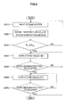
- FIG 3 is a flow chart illustrating the method for controlling the washing machine of the present invention.
- S denotes an operation.
- the method of controlling the washing machine comprises the operation (S100-S200) of supplying water to the tub 11 dependent on the steam washing cycle selected by a user; operations (S300-S400) wherein the water supplied to the inside of the tub 11 is heated using the heater 40; operations (S500-S600) wherein the water and laundry in the tub 11 is further heated by spraying steam of a high temperature of at least 100°C thereonto; an operation (S700) wherein a washing operation is performed dependent on a washing cycle selected by the user after the water and the laundry is heated by the heater 40 and the heater; and an operation (S800) wherein rinsing, dehydrating and drying operations are performed after the washing operation is completed.
- the operating data selected by the user is inputted to the control unit 130 through the signal input unit 100 (S100).
- a washing cycle for example, a steam washing course
- a washing temperature for example, a washing temperature
- a dehydrating rotation speed for example, a washing temperature
- an additional rinsing operation the operating data selected by the user is inputted to the control unit 130 through the signal input unit 100 (S100).
- the control unit 130 then opens the first water supply valve 22 on so that wash water is supplied to the detergent supply device 18, wherein detergent is dissolved in the water and is then supplied to the tub 11 (S200).
- the method of controlling the washing machine comprising the water circulating device 60 does not require water to be supplied to a level in the drum 12 to soak the laundry and so the quantity of wash water required is reduced as compared to conventional washing machines.
- control unit 130 After a predetermined quantity of the water is supplied to the inside of the tub 11, the control unit 130 turns the first water supply valve 22 off so that the supply of water to the first water supply pipe 21 is stopped.
- the heater 40 is operated by the control unit 130, thereby heating the wash water in the tub 11 (S300).
- the temperature of the water heated by the heater 40 is rapidly increased, thereby shortening the overall washing time and reducing the quantity of energy consumed to heat the water.
- T1 the time taken to heat the wash water to the temperature required to perform a washing operation using the heater 40
- S400 the operation of the heater 40 is stopped.
- control unit 130 controls the second water valve 25 such that water is supplied to the steam generating device 30 through the second water supply pipe 24, and this water is rapidly heated by the steam heater 32 to generate high temperature steam of at least 100°C.
- the at high temperature steam is supplied to the inside of the tub 11 through the steam supply pipe 36 and the discharge nozzle 38, and serves to additionally heat the water and the laundry in the tub 11, which were previously heated by the heater 40 (S500).
- the temperature of the water is rapidly increased compared to the conventional method, in which the water is heated only by the heater 40 installed in the lower portion of the tub 11, thereby remarkably shortening the overall washing time and reducing the quantity of energy consumed to heat the water.
- control unit 130 preheats the steam heater 32 installed in the steam generating device 30 (S510).
- the steam heater 32 is preheated so that the steam generating device 30, at an initial operating state, supplies pure steam, which is not mixed with water at room temperature (23 ⁇ 24°C), to the inside of the tub 11.
- the temperature sensing unit 120 senses a temperature (S T ) of the steam generating device 30 due to the preheating of the steam heater 32, and outputs the sensed temperature (S T ) to the control unit 130 (S520).
- S TS predetermined reference temperature
- S TS the lowermost temperature for heating the steam heater 32 to generate steam, approximately 100°C
- the second water valve 25 When the second water valve 25 is turned on, the water is supplied to the steam generating device 30 through the second water supply pipe 24, and the water supplied to the steam generating device 30 is rapidly heated by the steam heater 32 to generate steam at a high temperature steam of at least 100°C.
- the high temperature steam is supplied to the inside of the tub 11 through the steam supply pipe 36 and the discharge nozzle 38, and additionally heats the water and the laundry in the tub 11, which were previously heated by the heater 40.
- a time during the turning off of the second steam valve 25 is checked, and when a designated time (T4; a time taken to increase the temperature of the steam generating device 30 to a high temperature of at least 100°C, approximately 10 seconds) has elapsed (S570), the control unit 130 turns the second steam valve 25 on again until the designated time (T2) elapses, thereby repeating the above process.
- T4 a designated time
- T2 a time taken to increase the temperature of the steam generating device 30 to a high temperature of at least 100°C, approximately 10 seconds
Abstract
Description
- The present invention relates to a method of controlling a washing machine including a steam generating device having a temperature sensor and, a control unit for supplying water to the steam generating device to generate steam.
- A drum washing machine washes laundry by elevating and then dropping the laundry in a cylindrical drum when the drum is rotated. Compared to a conventional pulsator washing machine, a drum washing machine has a long washing time, but minimises laundry damage and consumes a small amount of wash water. Therefore, drum type washing machines have become more popular.
- Japanese Patent Laid-open Publication No. 2001-149685 discloses a drum washing machine with a device for heating water with which to wash the laundry.
- The above mentioned washing machine comprises a tub to contain water, a drum rotatably installed in the tub and rotated by a driving motor, and a heater installed below the tub to heat the water contained in the tub.
- To perform a washing operation with this type of washing machine the laundry together with water are contained in the tub, wherein the laundry is elevated along the inner circumferential surface of the drum due to the rotation of the drum in the tub and then dropped, thereby washing the laundry. Additionally, the heater heating the water increases the washing efficiency of the washing machine.
- A disadvantage of the above conventional washing machine is that it takes a long time to heat the water to a desired temperature in which to wash the laundry as the heater is required to heat a large amount of water contained in the tub, thereby requiring an increased overall washing time.
- The present invention seeks to provide a method of controlling a washing machine which overcomes or substantially alleviates the problems discussed above.
- A method of controlling a washing machine according to the present invention is characterised in that the method includes the step of sensing the temperature of the steam generating device and supplying water to the steam generating device when a predetermined temperature has been reached.
- Preferably, the method the method includes the step of terminating the supply of water to the steam generating device when a predetermined period of time has elapsed.
- In a preferred embodiment, the first predetermined time is the time taken for the steam generating device to generate steam from the water supplied thereto.
- The method may further include the step of reinitiating the supply of water to the steam generating device when a second predetermined period of time has elapsed.
- Advantageously, the second predetermined period of time is the time taken for the steam generating device to reach said predetermined temperature.
- Embodiments of the present invention will now be described, by way of example only, with reference to the accompanying drawings, in which:
- Figure 1 is a longitudinal sectional view of a washing machine according to the present invention;
- Figure 2 is a block diagram of a washing machine in according to the present invention;
- Figure 3 is a flow chart illustrating a method for controlling the washing machine according to the present invention; and
- Figure 4 is a flow chart illustrating a detailed process for heating wash water and laundry using steam in the method of Figure 3.
- Referring now to the drawings, there is shown in Figure 1 a washing machine comprising a drum-type tub 11 installed in a
main body 10 to hold water, and adrum 12 rotatably installed in the tub 11. - The tub 11 is aligned in the washing machine at a designated angle (α) to the base of the washing machine such that a
front surface 11a of the tub 11, through which aninlet 11b is formed, is higher than that of a rear surface 11c of the tub 11, and thedrum 12 installed in the tub 11 is inclined in the same manner as the tub 11 such that afront surface 12a of thedrum 12, through which aninlet 12b is formed, is higher than that of arear surface 12c of thedrum 12. - A rotational central line A of the
drum 12 is therefore at the designated angle (α) to the base of the washing machine. Arotary shaft 13 is connected to the centre of therear surface 12c of thedrum 12 and is rotatably supported by the centre of the rear surface 11c of the tub 11, thereby allowing thedrum 12 to be rotated in the tub 11. - A plurality of through
holes 12d are formed through the circumferential surface of thedrum 12 and a plurality ofdrain holes 12e are formed through the outer portion of thefront surface 12a of thedrum 12 to discharge water in thedrum 12 when thedrum 12 is rotated at a high speed. Further, a plurality oflifters 14 are installed along the inner surface of thedrum 12 to elevate and drop laundry when thedrum 12 is rotated, - A
motor 15, is installed on an outer portion of the rear surface 11c of the tub 11 and serves as a driving device to rotate therotary shaft 13 connected to thedrum 12. Themotor 15 includes astator 15a fixed to the rear surface 11c of the tub 11, arotor 15b rotatably disposed outside thestator 15a, and adriving plate 15c which connects therotor 15b and therotary shaft 13. - An
inlet 16 to allow laundry to be inserted or removed from thedrum 12 is formed through the front surface of themain body 10 and corresponds to the positions of theinlet 12b of thedrum 12 and theinlet 11b of the tub 11 and adoor 17 is installed at theinlet 16. - A
detergent supply device 18 to supply a detergent to the inside of the tub 11, asteam generating device 30 to supply steam to the inside of the tub 11, and awater supply device 20 to supply water to the tub 11 and thesteam generating device 30 are installed above the tub 11. - The
detergent supply device 18 includes a space to contain the detergent therein, and is installed to be accessible from the front surface of themain body 10 so that a user can easily place detergent into thedetergent supply device 18. - The
water supply device 20 includes a firstwater supply pipe 21 to supply water to the inside of the tub 11, and a firstwater supply valve 22 installed in thewater supply pipe 21 to control the supply of water to the firstwater supply pipe 21. The firstwater supply pipe 21 is connected to thedetergent supply device 18 so that water is supplied to thedetergent supply device 18 and aconnection pipe 23 is installed between thedetergent supply device 18 and the tub 11 such that water passing through thedetergent supply device 18 dissolves detergent in thedetergent supply device 18 therein and is then supplied to the tub 11. - The
water supply device 20 further includes a secondwater supply pipe 24 to supply water to thesteam generating device 30 and a secondwater supply valve 25 installed in the secondwater supply pipe 24 controls the supply of water to thesteam generating device 30. - Although the
water supply device 20 includes thewater supply valves water supply device 20 may include integrating thewater supply valves - The
steam generating device 30 includes a U-shapedsteam heater 32 installed therein to rapidly heat water passing therethrough to generate steam at a high temperature of at least 100°C, atemperature sensor 34 installed at one side of thesteam generating device 30 to sense the temperature of thesteam generating device 30, asteam supply pipe 36 which extends from thesteam generating device 30 to the tub 11, and adischarge nozzle 38 installed at an outlet of thesteam supply pipe 36. - Although the
steam heater 32 is installed in thesteam generating device 30, as described above, the present invention is not limited thereto. For example, thesteam heater 32 may be an external heater having a structure contacting the external surface of an upper or lower portion of thesteam generating device 30 or surrounding the external circumferential surface of thesteam generating device 30. - A
heater 40 to heat the water supplied to the inside of the tub 11 is installed in the lower portion of the tub 11. Aheater receiving portion 41 to receive theheater 40 and collect a designated quantity of the water is formed in the lower surface of the tub 11 such that theheater receiving portion 41 has a downwardly protruded structure. This structure of theheater receiving portion 41 allows theheater 40 to be submerged in the water collected in theheater receiving portion 41. - The washing machine of the present invention further comprises a
drain device 50 to discharge the water from the tub 11, and awater circulating device 60 to supply water heated by theheater 40 in the tub 11 to the inside of thedrum 12. - The
drain device 50 includes afirst drain pipe 51 connected to adrain hole 42 formed through theheater receiving portion 41 on the lower surface of the tub 11 to guide water out of the tub 11, adrain pump 52 installed in thefirst drain pipe 51, and asecond drain pipe 53 connected to an outlet of thedrain pump 52. - The
water circulation device 60 includes achannel change valve 61 installed in thesecond drain pipe 53, awater circulating pipe 62 extended from thechannel change valve 61 to theinlet 12b of thedrum 12, and aspray nozzle 63 installed at the outlet of thewater circulating pipe 62. Thechannel change valve 61 changes the flow path of the water at the outlet of thedrain pump 52 such that it is discharged to the outside or flows to thewater circulating pipe 62, and is in this embodiment an electric three-way valve. - Hereinafter, the operation of the above-described washing machine will be described.
- To operate the washing machine, laundry is placed in the
drum 12 and detergent is placed in thedetergent supply device 18, wherein the firstwater supply valve 22 of thewater supply device 20 is opened so that water is supplied to thedetergent supply device 18. - The detergent in the
detergent supply device 18 is dissolved in the water and thereinafter supplied to the tub 11. As the washing machine comprises thewater circulating device 60, it does not need to supply water to a level inside thedrum 12 to soak the laundry, thereby reducing the quantity of water required compared to the conventional washing machine. - After the supply of the water to the inside of the
drum 12 is completed, theheater 40 is operated to heat the water in the tub 11. Since the washing machine requires a small quantity of water compared to a conventional washing machine, the temperature of the water heated by theheater 40 is rapidly increased, thereby shortening overall washing time and reducing the quantity of energy consumed to heat the water. - After the water is heated by the
heater 40 to a desired temperature required to wash the laundry, thechannel change valve 61 of thewater circulating device 60 is operated. Then, the channel is formed such that the outlet of thedrain pump 52 communicates with thewater circulating pipe 62, and the water at the lower portion of the tub 11 is supplied to the inside of thedrum 12 through thefirst drain pipe 51 and thewater circulating pipe 62 by the operation of thedrain pump 52. - Since the water supplied to the inside of the
drum 12 is sprayed onto the laundry through thespray nozzle 63, the water uniformly soaks the laundry. A washing operation is performed wherein thedrum 12 is rotated by themotor 15 at a low speed. - During the washing operation, when the level of the water in the
drum 12 is above the height of thedrain holes 12e, the water flows into the tub 11 through thedrain holes 12e. The water is circulated from the tub 11 to the inside of thedrum 12 through thefirst drain pipe 51 and thewater circulating pipe 62 by the operation of thedrain pump 52. - When a user selects a steam cycle, the second
water supply valve 25 is opened so that water is supplied to thesteam generating device 30 through the secondwater supply pipe 24, wherein the water supplied is rapidly heated by theheater 32 to generate a high temperature steam of at least 100°C. - The high temperature steam is supplied to the inside of the tub 11 through the
steam supply pipe 36 and thedischarge nozzle 38, and serves to additionally heat the water and the laundry in the tub 11, which were previously heated by theheater 40. - When the water and laundry temperatures are increased to a predetermined temperature by the circulation of the water and the supply of steam, the supply of the steam is stopped and the
drum 12 is rotated by themotor 15 at low speed thereby achieving a washing operation. - After the washing operation is completed, a rinsing operation, in which dehydration and the repeated supply of water occurs, is performed. During the rinsing operation, the first
water supply valve 22 is opened so that water is supplied to the inside of the tub 11 through the firstwater supply pipe 21. Thechannel change valve 61 is opened so that the outlet of thedrain pump 52 is opened toward theexternal drain pipe 53, and thedrain pump 52 is operated, thereby discharging the water in the tub 11. When a final dehydrating operation is performed after the rinsing operation, thedrain pump 52 is operated under the condition that the outlet of thedrain pump 52 is opened toward theexternal drain pipe 53, and thedrum 12 is rotated at a high speed for a designated time, thereby dehydrating the laundry in the tub 11. - Referring to Figure 2, the washing machine comprises a
signal input unit 100, a waterlevel sensing unit 110, atemperature sensing unit 120, acontrol unit 130, and anoperating unit 140. - The
signal input unit 100 allows a user to input selected operating data, such as a washing cycle, a washing temperature, a dehydrating rotation speed, and an additional rinsing operation. The waterlevel sensing unit 110 senses the level of the water supplied to the inside of the tub 11. Thetemperature sensing unit 120 includes atemperature sensor 34 to sense the temperature of the water supplied to the tub 11 and the temperature of thesteam generating device 30. - The
control unit 130 is a microcomputer to control the washing machine according to the operating data inputted from thesignal input unit 100. Thecontrol unit 130 controls operations of thesteam valve 25 and thesteam heater 32 dependent on the temperature sensed by thetemperature sensing unit 120, thereby causing thesteam generating device 30 to generate a large quantity of steam at a high temperature of at least 100°C. - The
operating unit 140 operates themotor 15, thewater supply valves steam heater 32, theheater 40, thedrain pump 52, and thechannel change valve 61 based on an operation control signal of thecontrol unit 130. - Hereinafter, the operation and effects of the above-described washing machine and a method for controlling the same will be described in detail.
- Figure 3 is a flow chart illustrating the method for controlling the washing machine of the present invention. In Figure 3, "S" denotes an operation.
- The method of controlling the washing machine according to the present invention comprises the operation (S100-S200) of supplying water to the tub 11 dependent on the steam washing cycle selected by a user; operations (S300-S400) wherein the water supplied to the inside of the tub 11 is heated using the
heater 40; operations (S500-S600) wherein the water and laundry in the tub 11 is further heated by spraying steam of a high temperature of at least 100°C thereonto; an operation (S700) wherein a washing operation is performed dependent on a washing cycle selected by the user after the water and the laundry is heated by theheater 40 and the heater; and an operation (S800) wherein rinsing, dehydrating and drying operations are performed after the washing operation is completed. - Hereinafter, the method of controlling the washing machine according to the present invention will be described in detail.
- When the user selects operating data, such as a washing cycle (for example, a steam washing course), a washing temperature, a dehydrating rotation speed, and an additional rinsing operation, the operating data selected by the user is inputted to the
control unit 130 through the signal input unit 100 (S100). - The
control unit 130 then opens the firstwater supply valve 22 on so that wash water is supplied to thedetergent supply device 18, wherein detergent is dissolved in the water and is then supplied to the tub 11 (S200). - The method of controlling the washing machine comprising the
water circulating device 60, does not require water to be supplied to a level in thedrum 12 to soak the laundry and so the quantity of wash water required is reduced as compared to conventional washing machines. - After a predetermined quantity of the water is supplied to the inside of the tub 11, the
control unit 130 turns the firstwater supply valve 22 off so that the supply of water to the firstwater supply pipe 21 is stopped. - After the supply of the water is completed, the
heater 40 is operated by thecontrol unit 130, thereby heating the wash water in the tub 11 (S300). As a small quantity of water is required compared to a conventional method, the temperature of the water heated by theheater 40 is rapidly increased, thereby shortening the overall washing time and reducing the quantity of energy consumed to heat the water. - Once a designated time for operating the
heater 40 is determined (T1; the time taken to heat the wash water to the temperature required to perform a washing operation using the heater 40) has elapsed (S400), the operation of theheater 40 is stopped. - Thereafter, the
control unit 130 controls thesecond water valve 25 such that water is supplied to thesteam generating device 30 through the secondwater supply pipe 24, and this water is rapidly heated by thesteam heater 32 to generate high temperature steam of at least 100°C. - The at high temperature steam is supplied to the inside of the tub 11 through the
steam supply pipe 36 and thedischarge nozzle 38, and serves to additionally heat the water and the laundry in the tub 11, which were previously heated by the heater 40 (S500). - As a small quantity of water is required due to the use of the
water circulating device 60 and a large quantity of high temperature steam is supplied of at least 100°C to the inside of the tub 11 through thesteam generating device 30, the temperature of the water is rapidly increased compared to the conventional method, in which the water is heated only by theheater 40 installed in the lower portion of the tub 11, thereby remarkably shortening the overall washing time and reducing the quantity of energy consumed to heat the water. - Further, since high temperature steam is sprayed onto the laundry, which is sufficiently soaked by the wash water, the temperature of the laundry is rapidly increased, thereby shortening the washing time and improving the detergency to increase the washing effects of the washing machine.
- Once it is determined that a designated time (T2; overall operating time of the
steam generating device 30 from a point of the time when thesteam heater 32 is preheated, approximately 6~10 minutes) has elapsed (S600), the operation of thesteam heater 32 is stopped, and thedrum 12 is rotated at a low speed by the operation of themotor 15 so that the washing operation is performed according to the selected washing cycle (S700). - When the washing operation is completed, at least one or all of rinsing, dehydrating, and drying operations is performed according to the selected operating data, and the steam washing cycle is terminated (S800).
- Hereinafter, with reference to Figure 4, a process to heat the water and the laundry using steam in the method for controlling the washing machine as shown in Figure 3 will be described in more detail.
- In order to supply a large quantity of high temperature steam to the inside of the tub 11, the
control unit 130 preheats thesteam heater 32 installed in the steam generating device 30 (S510). - The
steam heater 32 is preheated so that thesteam generating device 30, at an initial operating state, supplies pure steam, which is not mixed with water at room temperature (23~24°C), to the inside of the tub 11. - The
temperature sensing unit 120 senses a temperature (ST) of thesteam generating device 30 due to the preheating of thesteam heater 32, and outputs the sensed temperature (ST) to the control unit 130 (S520). When thecontrol unit 130 determines that the temperature (ST) of thesteam generating device 30 inputted from thetemperature sensing unit 120 has exceeded a predetermined reference temperature (STS; the lowermost temperature for heating thesteam heater 32 to generate steam, approximately 100°C) (S530). Thecontrol unit 130 turns the secondwater supply valve 25 on (S540). - When the
second water valve 25 is turned on, the water is supplied to thesteam generating device 30 through the secondwater supply pipe 24, and the water supplied to thesteam generating device 30 is rapidly heated by thesteam heater 32 to generate steam at a high temperature steam of at least 100°C. - The high temperature steam is supplied to the inside of the tub 11 through the
steam supply pipe 36 and thedischarge nozzle 38, and additionally heats the water and the laundry in the tub 11, which were previously heated by theheater 40. - Thereafter, when a designated time (T3; a time taken to generate steam at a high temperature of at least 100°C, approximately 2 seconds) has elapsed (S550), the
control unit 130 turns thesteam valve 25 off (S560). - A time during the turning off of the
second steam valve 25 is checked, and when a designated time (T4; a time taken to increase the temperature of thesteam generating device 30 to a high temperature of at least 100°C, approximately 10 seconds) has elapsed (S570), thecontrol unit 130 turns thesecond steam valve 25 on again until the designated time (T2) elapses, thereby repeating the above process. - Although embodiments of the present invention have been shown and described, it will be appreciated by those skilled in the art that changes may be made to the embodiments without departing from the principles of the invention, the scope of which is defined in the claims and their equivalents and the foregoing description should be regarded as a description of preferred embodiments only.
Claims (20)
- A method of controlling a washing machine including a steam generating device having a temperature sensor and, a control unit for supplying water to the steam generating device to generate steam, characterised in that the method includes the step of sensing the temperature of the steam generating device and supplying water to the steam generating device when a predetermined temperature has been reached.
- A method according to claim 1, wherein the method includes the step of terminating the supply of water to the steam generating device when a predetermined period of time has elapsed.
- A method according to claim 2, wherein the first predetermined time is the time taken for the steam generating device to generate steam from the water supplied thereto.
- A method according to claim 2 or claim 3, wherein the method includes the step of reinitiating the supply of water to the steam generating device when a second predetermined period of time has elapsed.
- A method according to claim 4, wherein the second predetermined period of time is the time taken for the steam generating device to reach said predetermined temperature.
- A washing machine including a steam generating device, a temperature sensor for sensing the temperature of the steam generating device and, a control unit for supplying water to the steam generating device to generate steam, characterised in that the control unit is configured to supply water to the steam generating device when the steam generating device has reached a predetermined temperature as sensed by the temperature sensor.
- A washing machine according to claim 6, wherein the control means is configured to terminate the supply of water to the steam generating device when a predetermined time period has elapsed.
- A washing machine according to claim 7, wherein the control means is configured to reinitiate the supply of water to the steam generating device when a second predetermined period of time has elapsed.
- A method for controlling a washing machine, which heats supplied water using a steam generating device to generate steam, comprising sensing a temperature of the steam generating device, controlling water supply means for supplying water to the steam generating device according to the sensed temperature of the steam generating device, and performing a steam operation for controlling the steam generated from the steam generating device according to a time taken to control the water supply means.
- The method as set forth in claim 9 wherein the water supply means is controlled such that the wash water is supplied to the steam generating device when the temperature of the steam generating device is more than a predetermined reference temperature.
- The method as set forth in claim 9 wherein the water supply means is controlled such that the wash water supplied to the steam generating device is cut off when the temperature of the steam generating device is not more than a predetermined reference temperature.
- The method as set forth in claim 9 wherein the wash water supplied to the steam generating device is cut off to stop generation of the steam, when a time during which the water supply means is turned on to supply water exceeds a predetermined water supply time.
- The method as set forth in claim 9 wherein the wash water is supplied to the steam generating device to generate the steam, when a time during which the water supply means is turned off to stop supplying water exceeds a predetermined water supply stop time.
- A method for controlling a washing machine, which heats supplied wash water using a steam generating device to generate steam, comprising preheating the steam generating device before wash water is supplied to the steam generating device sensing a temperature of the preheated steam generating device, controlling water supply means for supplying the wash water to the steam generating device by comparing the sensed temperature of the steam generating device to a predetermined reference temperature and controlling the generation of the steam by comparing a time, taken to control the water supply means to a predetermined water supply time and a predetermined water supply stop time.
- The method as set forth in claim 14 wherein the wash water supplied to the steam generating device is cut off to stop the generation of the steam, when a time during which the water supply means I turned on to supply water exceeds the predetermined water supply time.
- The method as set forth in claim 14 wherein the wash water is supplied to the steam generating device to generate the steam, when a time during which the water supply means is turned off to stop supplying water exceeds the predetermined water supply stop time.
- A washing machine having a steam generating device for heating supplied wash water to generate steam comprising a temperature sensing unit for sensing a temperature of the steam generating device, water supply means for supplying wash water to the steam generating device, and a control unit for controlling the water supply means such that the steam generated from the steam generating device is controlled according to the temperature of the steam generating device.
- The washing machine as set forth in claim 17 wherein the control unit controls the steam generating device such that the steam generating device is preheated before the wash water is supplied to the steam generating device.
- The washing machine as set forth in claim 17 wherein the control unit compares a time, taken to control the water supply means to a predetermined water supply time and a predetermined water supply stop time, and controls the generation of the steam according to the result of the comparison.
- The washing machine as set forth in claim 17 wherein the water supply means is a steam valve capable of being turned on and off so as to control the wash water supplied to the steam generating device according to control of the control unit.
Applications Claiming Priority (1)
| Application Number | Priority Date | Filing Date | Title |
|---|---|---|---|
| KR1020040094773A KR20060055222A (en) | 2004-11-18 | 2004-11-18 | Washing machine and control method thereof |
Publications (2)
| Publication Number | Publication Date |
|---|---|
| EP1659205A2 true EP1659205A2 (en) | 2006-05-24 |
| EP1659205A3 EP1659205A3 (en) | 2009-01-14 |
Family
ID=35892558
Family Applications (1)
| Application Number | Title | Priority Date | Filing Date |
|---|---|---|---|
| EP05105646A Withdrawn EP1659205A3 (en) | 2004-11-18 | 2005-06-23 | Washing machine |
Country Status (6)
| Country | Link |
|---|---|
| US (1) | US20060101586A1 (en) |
| EP (1) | EP1659205A3 (en) |
| JP (1) | JP2006141985A (en) |
| KR (1) | KR20060055222A (en) |
| CN (1) | CN1776073A (en) |
| RU (1) | RU2294994C1 (en) |
Cited By (27)
| Publication number | Priority date | Publication date | Assignee | Title |
|---|---|---|---|---|
| WO2008014924A1 (en) * | 2006-07-31 | 2008-02-07 | Electrolux Home Products Corporation N.V. | Process to control a steam unit of a domestic appliance |
| EP1889960A2 (en) * | 2006-08-15 | 2008-02-20 | Whirpool Corporation | Water supply control for a steam generator of a fabric treatment appliance |
| EP2006432A2 (en) | 2007-06-19 | 2008-12-24 | Miele & Cie. KG | Method for operating a laundry handling machine with steam creation device and laundry handling machine |
| EP2006436A2 (en) | 2007-06-19 | 2008-12-24 | Miele & Cie. KG | Front loaded laundry treatment machine with steam creation device |
| US7665332B2 (en) | 2006-08-15 | 2010-02-23 | Whirlpool Corporation | Steam fabric treatment appliance with exhaust |
| US7681418B2 (en) | 2006-08-15 | 2010-03-23 | Whirlpool Corporation | Water supply control for a steam generator of a fabric treatment appliance using a temperature sensor |
| US7690062B2 (en) | 2007-08-31 | 2010-04-06 | Whirlpool Corporation | Method for cleaning a steam generator |
| US7730568B2 (en) | 2006-06-09 | 2010-06-08 | Whirlpool Corporation | Removal of scale and sludge in a steam generator of a fabric treatment appliance |
| US7753009B2 (en) | 2006-10-19 | 2010-07-13 | Whirlpool Corporation | Washer with bio prevention cycle |
| EP2208818A1 (en) | 2009-01-19 | 2010-07-21 | Whirpool Corporation | Washing machine provided with a self-controlled and self-cleaned flowthrough steamer generator |
| US7765628B2 (en) | 2006-06-09 | 2010-08-03 | Whirlpool Corporation | Steam washing machine operation method having a dual speed spin pre-wash |
| US7841219B2 (en) | 2006-08-15 | 2010-11-30 | Whirlpool Corporation | Fabric treating appliance utilizing steam |
| US7861343B2 (en) | 2007-08-31 | 2011-01-04 | Whirlpool Corporation | Method for operating a steam generator in a fabric treatment appliance |
| US7886392B2 (en) | 2006-08-15 | 2011-02-15 | Whirlpool Corporation | Method of sanitizing a fabric load with steam in a fabric treatment appliance |
| US7905119B2 (en) | 2007-08-31 | 2011-03-15 | Whirlpool Corporation | Fabric treatment appliance with steam generator having a variable thermal output |
| US7918109B2 (en) | 2007-08-31 | 2011-04-05 | Whirlpool Corporation | Fabric Treatment appliance with steam generator having a variable thermal output |
| US7941885B2 (en) | 2006-06-09 | 2011-05-17 | Whirlpool Corporation | Steam washing machine operation method having dry spin pre-wash |
| US7966683B2 (en) | 2007-08-31 | 2011-06-28 | Whirlpool Corporation | Method for operating a steam generator in a fabric treatment appliance |
| EP2339064A2 (en) * | 2008-08-28 | 2011-06-29 | Daewoo Electronics Corporation | Steam dryer control method |
| US8037565B2 (en) | 2007-08-31 | 2011-10-18 | Whirlpool Corporation | Method for detecting abnormality in a fabric treatment appliance having a steam generator |
| EP2402498A1 (en) | 2010-07-02 | 2012-01-04 | Miele & Cie. KG | Method for operating a laundry handling machine with steam creation device and laundry handling machine |
| US8393183B2 (en) | 2007-05-07 | 2013-03-12 | Whirlpool Corporation | Fabric treatment appliance control panel and associated steam operations |
| US8555676B2 (en) | 2007-08-31 | 2013-10-15 | Whirlpool Corporation | Fabric treatment appliance with steam backflow device |
| US8555675B2 (en) | 2007-08-31 | 2013-10-15 | Whirlpool Corporation | Fabric treatment appliance with steam backflow device |
| EP2826909A1 (en) * | 2013-07-19 | 2015-01-21 | Electrolux Appliances Aktiebolag | Method for operating a steam generation unit in a laundry dryer and method of operating a laundry dryer |
| EP2860297A4 (en) * | 2012-06-06 | 2015-07-22 | Panasonic Ip Man Co Ltd | Clothes treatment device |
| EP2081479A4 (en) * | 2007-03-31 | 2017-01-04 | LG Electronics Inc. | Dish washing machine and control method of the same |
Families Citing this family (36)
| Publication number | Priority date | Publication date | Assignee | Title |
|---|---|---|---|---|
| RU2380463C1 (en) * | 2005-03-16 | 2010-01-27 | ЭлДжи ЭЛЕКТРОНИКС ИНК. | Washing machine and method to control it |
| EP1861531B2 (en) * | 2005-03-25 | 2015-01-14 | LG Electronics Inc. | Steam generator, and laundry device and method thereof |
| WO2007055510A1 (en) * | 2005-11-10 | 2007-05-18 | Lg Electronics Inc. | Steam generator and laundry dryer having the same and controlling method thereof |
| US20070283509A1 (en) * | 2006-06-09 | 2007-12-13 | Nyik Siong Wong | Draining liquid from a steam generator of a fabric treatment appliance |
| US20070283728A1 (en) * | 2006-06-09 | 2007-12-13 | Nyik Siong Wong | Prevention of scale and sludge in a steam generator of a fabric treatment appliance |
| US7627920B2 (en) | 2006-06-09 | 2009-12-08 | Whirlpool Corporation | Method of operating a washing machine using steam |
| KR100793800B1 (en) * | 2006-06-30 | 2008-01-11 | 엘지전자 주식회사 | Washing machine and control method of steam generator for the same |
| KR101328918B1 (en) * | 2006-07-10 | 2013-11-14 | 엘지전자 주식회사 | Laundry Machine and Operating Method for the Same |
| US7591859B2 (en) | 2006-08-15 | 2009-09-22 | Whirlpool Corporation | Water supply control for a steam generator of a fabric treatment appliance using a weight sensor |
| US20080040869A1 (en) * | 2006-08-15 | 2008-02-21 | Nyik Siong Wong | Determining Fabric Temperature in a Fabric Treating Appliance |
| EP2061922B1 (en) | 2006-09-08 | 2016-11-02 | LG Electronics Inc. | Laundry machine and controlling method of the same |
| US20080095660A1 (en) * | 2006-10-19 | 2008-04-24 | Nyik Siong Wong | Method for treating biofilm in an appliance |
| KR101319873B1 (en) * | 2006-12-14 | 2013-10-18 | 엘지전자 주식회사 | laundry device and control method of the same |
| KR101253179B1 (en) * | 2006-12-14 | 2013-04-12 | 엘지전자 주식회사 | laundry dryer |
| KR101136863B1 (en) | 2007-02-28 | 2012-04-20 | 삼성전자주식회사 | Washing machine |
| KR100930896B1 (en) * | 2007-06-08 | 2009-12-10 | 엘지전자 주식회사 | Water supply control method from washing machine to steam generator and washing machine |
| DE102008026114B4 (en) | 2007-06-08 | 2020-08-06 | Lg Electronics Inc. | Control method for a steam generator and clothing treatment machine with the same |
| JP5053723B2 (en) * | 2007-06-15 | 2012-10-17 | 株式会社東芝 | Drum-type washing machine and washing method |
| KR20090035898A (en) * | 2007-10-08 | 2009-04-13 | 엘지전자 주식회사 | Washing method of washing machine |
| US8567219B2 (en) * | 2007-11-01 | 2013-10-29 | Lg Electronics Inc. | Washing machine |
| DE102007058833A1 (en) * | 2007-11-30 | 2009-06-10 | E.G.O. Elektro-Gerätebau GmbH | Heating device for a washing machine, washing machine with a heating device and method for operating a heating device |
| KR101521175B1 (en) * | 2008-04-22 | 2015-05-20 | 삼성전자 주식회사 | Washing machine and method of controlling the same |
| CN101570932B (en) * | 2008-04-29 | 2012-06-27 | 海尔集团公司 | Washing machine with improved water way |
| ITTO20080327A1 (en) * | 2008-04-30 | 2009-11-01 | Indesit Co Spa | METHOD AND DEVICE FOR SOFTENING FOLDS IN CLOTHES IN A WASHING MACHINE OR WASHING MACHINE |
| KR101440296B1 (en) * | 2008-08-13 | 2014-09-15 | 동부대우전자 주식회사 | Steam control method for drum type washing machine |
| KR101440295B1 (en) * | 2008-08-13 | 2014-09-15 | 동부대우전자 주식회사 | Steam control device and method for drum type washing machine |
| KR101590371B1 (en) * | 2009-02-16 | 2016-02-02 | 엘지전자 주식회사 | Washing machine and washing method |
| JP5377189B2 (en) * | 2009-09-24 | 2013-12-25 | シャープ株式会社 | Washing machine |
| US8671488B2 (en) * | 2010-02-03 | 2014-03-18 | Daewoo Electronics Corporation | Steam control device and method of drum washing machine |
| KR20140098485A (en) | 2013-01-31 | 2014-08-08 | 엘지전자 주식회사 | washing machine and a control method of the same |
| KR101634190B1 (en) * | 2013-01-31 | 2016-06-28 | 엘지전자 주식회사 | washing machine and a control method of the same |
| KR102426405B1 (en) * | 2016-01-04 | 2022-07-28 | 엘지전자 주식회사 | Dishwasher and Control Method of the dish washer |
| CN105970541A (en) * | 2016-06-29 | 2016-09-28 | 无锡小天鹅股份有限公司 | Washing control method of roller washing machine and roller washing machine |
| CN106283477B (en) * | 2016-09-30 | 2018-06-19 | 合肥美的洗衣机有限公司 | Roller washing machine |
| CN106367928B (en) * | 2016-09-30 | 2018-06-19 | 合肥美的洗衣机有限公司 | Rotary drum washing machine |
| CN116926845A (en) * | 2022-03-29 | 2023-10-24 | 无锡飞翎电子有限公司 | Clothes treatment device, steam control method and device thereof and storage medium |
Citations (1)
| Publication number | Priority date | Publication date | Assignee | Title |
|---|---|---|---|---|
| EP1464751A1 (en) * | 2003-03-31 | 2004-10-06 | Lg Electronics Inc. | Steam jet drum washing machine |
Family Cites Families (8)
| Publication number | Priority date | Publication date | Assignee | Title |
|---|---|---|---|---|
| US1501746A (en) * | 1923-03-31 | 1924-07-15 | Martin W Carter | Washing machine |
| US1852179A (en) * | 1926-05-11 | 1932-04-05 | Thomas J Mcdonald | Steam washing machine |
| US4343987A (en) * | 1979-05-14 | 1982-08-10 | Aqua-Chem, Inc. | Electric boiler |
| US5561880A (en) * | 1994-11-14 | 1996-10-08 | A/C Enterprises, Inc. | Steam cabinet and steaming method |
| US5903709A (en) * | 1997-11-12 | 1999-05-11 | Jeng Der Electrode Heater Co., Ltd. | Electrode-type steam production device with automatically controlled water inlet and outlet valves |
| SE521337C2 (en) * | 1999-08-09 | 2003-10-21 | Electrolux Ab | Textile washing machine with steam drying |
| US7021087B2 (en) * | 2000-06-05 | 2006-04-04 | Procter & Gamble Company | Methods and apparatus for applying a treatment fluid to fabrics |
| US6811811B2 (en) * | 2001-05-04 | 2004-11-02 | Procter & Gamble Company | Method for applying a treatment fluid to fabrics |
-
2004
- 2004-11-18 KR KR1020040094773A patent/KR20060055222A/en not_active Application Discontinuation
-
2005
- 2005-06-15 CN CNA2005100764514A patent/CN1776073A/en active Pending
- 2005-06-16 US US11/153,388 patent/US20060101586A1/en not_active Abandoned
- 2005-06-16 RU RU2005118694/12A patent/RU2294994C1/en not_active IP Right Cessation
- 2005-06-23 EP EP05105646A patent/EP1659205A3/en not_active Withdrawn
- 2005-07-08 JP JP2005200231A patent/JP2006141985A/en active Pending
Patent Citations (1)
| Publication number | Priority date | Publication date | Assignee | Title |
|---|---|---|---|---|
| EP1464751A1 (en) * | 2003-03-31 | 2004-10-06 | Lg Electronics Inc. | Steam jet drum washing machine |
Cited By (42)
| Publication number | Priority date | Publication date | Assignee | Title |
|---|---|---|---|---|
| US7730568B2 (en) | 2006-06-09 | 2010-06-08 | Whirlpool Corporation | Removal of scale and sludge in a steam generator of a fabric treatment appliance |
| US7941885B2 (en) | 2006-06-09 | 2011-05-17 | Whirlpool Corporation | Steam washing machine operation method having dry spin pre-wash |
| US7765628B2 (en) | 2006-06-09 | 2010-08-03 | Whirlpool Corporation | Steam washing machine operation method having a dual speed spin pre-wash |
| EP1887123A1 (en) * | 2006-07-31 | 2008-02-13 | Electrolux Home Products Corporation N.V. | Process to control a steam unit of a domestic appliance |
| RU2442849C2 (en) * | 2006-07-31 | 2012-02-20 | Электролюкс Хоум Продактс Корпорейшн Н.В. | Method for regulation of steam installation in home appliance |
| WO2008014924A1 (en) * | 2006-07-31 | 2008-02-07 | Electrolux Home Products Corporation N.V. | Process to control a steam unit of a domestic appliance |
| US7886392B2 (en) | 2006-08-15 | 2011-02-15 | Whirlpool Corporation | Method of sanitizing a fabric load with steam in a fabric treatment appliance |
| EP1889960A2 (en) * | 2006-08-15 | 2008-02-20 | Whirpool Corporation | Water supply control for a steam generator of a fabric treatment appliance |
| US7665332B2 (en) | 2006-08-15 | 2010-02-23 | Whirlpool Corporation | Steam fabric treatment appliance with exhaust |
| US7681418B2 (en) | 2006-08-15 | 2010-03-23 | Whirlpool Corporation | Water supply control for a steam generator of a fabric treatment appliance using a temperature sensor |
| US7904981B2 (en) | 2006-08-15 | 2011-03-15 | Whirlpool Corporation | Water supply control for a steam generator of a fabric treatment appliance |
| US7707859B2 (en) | 2006-08-15 | 2010-05-04 | Whirlpool Corporation | Water supply control for a steam generator of a fabric treatment appliance |
| EP1889966B2 (en) † | 2006-08-15 | 2015-10-21 | Whirlpool Corporation | Water supply control for a steam generator of a fabric treatment appliance using a temperature sensor |
| EP1889960A3 (en) * | 2006-08-15 | 2009-12-30 | Whirpool Corporation | Water supply control for a steam generator of a fabric treatment appliance |
| US7913339B2 (en) | 2006-08-15 | 2011-03-29 | Whirlpool Corporation | Water supply control for a steam generator of a fabric treatment appliance using a temperature sensor |
| US7841219B2 (en) | 2006-08-15 | 2010-11-30 | Whirlpool Corporation | Fabric treating appliance utilizing steam |
| US7753009B2 (en) | 2006-10-19 | 2010-07-13 | Whirlpool Corporation | Washer with bio prevention cycle |
| EP2081479A4 (en) * | 2007-03-31 | 2017-01-04 | LG Electronics Inc. | Dish washing machine and control method of the same |
| US10844533B2 (en) | 2007-05-07 | 2020-11-24 | Whirlpool Corporation | Method for controlling a household washing machine |
| US8393183B2 (en) | 2007-05-07 | 2013-03-12 | Whirlpool Corporation | Fabric treatment appliance control panel and associated steam operations |
| DE102007028617A1 (en) | 2007-06-19 | 2009-01-02 | Miele & Cie. Kg | Front-loadable laundry treatment machine with steam generator |
| US8904830B2 (en) | 2007-06-19 | 2014-12-09 | Miele & Cie. Kg | Front-loading laundry appliance having a steam generator device |
| DE102007028618A1 (en) | 2007-06-19 | 2009-01-02 | Miele & Cie. Kg | A method of operating a laundry treating machine with steam generating means and laundry treating machine |
| EP2006436A2 (en) | 2007-06-19 | 2008-12-24 | Miele & Cie. KG | Front loaded laundry treatment machine with steam creation device |
| DE102007028617B4 (en) * | 2007-06-19 | 2010-10-28 | Miele & Cie. Kg | Front-loadable laundry treatment machine with steam generator |
| EP2006432A2 (en) | 2007-06-19 | 2008-12-24 | Miele & Cie. KG | Method for operating a laundry handling machine with steam creation device and laundry handling machine |
| US8161662B2 (en) | 2007-06-19 | 2012-04-24 | Miele & Cie. Kg | Method for operating a laundry appliance having a steam generator device, and laundry appliance |
| EP2006432A3 (en) * | 2007-06-19 | 2010-12-22 | Miele & Cie. KG | Method for operating a laundry handling machine with steam creation device and laundry handling machine |
| US8555676B2 (en) | 2007-08-31 | 2013-10-15 | Whirlpool Corporation | Fabric treatment appliance with steam backflow device |
| US8037565B2 (en) | 2007-08-31 | 2011-10-18 | Whirlpool Corporation | Method for detecting abnormality in a fabric treatment appliance having a steam generator |
| US7690062B2 (en) | 2007-08-31 | 2010-04-06 | Whirlpool Corporation | Method for cleaning a steam generator |
| US7966683B2 (en) | 2007-08-31 | 2011-06-28 | Whirlpool Corporation | Method for operating a steam generator in a fabric treatment appliance |
| US7918109B2 (en) | 2007-08-31 | 2011-04-05 | Whirlpool Corporation | Fabric Treatment appliance with steam generator having a variable thermal output |
| US7905119B2 (en) | 2007-08-31 | 2011-03-15 | Whirlpool Corporation | Fabric treatment appliance with steam generator having a variable thermal output |
| US7861343B2 (en) | 2007-08-31 | 2011-01-04 | Whirlpool Corporation | Method for operating a steam generator in a fabric treatment appliance |
| US8555675B2 (en) | 2007-08-31 | 2013-10-15 | Whirlpool Corporation | Fabric treatment appliance with steam backflow device |
| EP2339064A4 (en) * | 2008-08-28 | 2013-04-24 | Daewoo Electronics Corp | Steam dryer control method |
| EP2339064A2 (en) * | 2008-08-28 | 2011-06-29 | Daewoo Electronics Corporation | Steam dryer control method |
| EP2208818A1 (en) | 2009-01-19 | 2010-07-21 | Whirpool Corporation | Washing machine provided with a self-controlled and self-cleaned flowthrough steamer generator |
| EP2402498A1 (en) | 2010-07-02 | 2012-01-04 | Miele & Cie. KG | Method for operating a laundry handling machine with steam creation device and laundry handling machine |
| EP2860297A4 (en) * | 2012-06-06 | 2015-07-22 | Panasonic Ip Man Co Ltd | Clothes treatment device |
| EP2826909A1 (en) * | 2013-07-19 | 2015-01-21 | Electrolux Appliances Aktiebolag | Method for operating a steam generation unit in a laundry dryer and method of operating a laundry dryer |
Also Published As
| Publication number | Publication date |
|---|---|
| RU2294994C1 (en) | 2007-03-10 |
| CN1776073A (en) | 2006-05-24 |
| RU2005118694A (en) | 2006-12-27 |
| US20060101586A1 (en) | 2006-05-18 |
| EP1659205A3 (en) | 2009-01-14 |
| JP2006141985A (en) | 2006-06-08 |
| KR20060055222A (en) | 2006-05-23 |
Similar Documents
| Publication | Publication Date | Title |
|---|---|---|
| EP1659205A2 (en) | Washing machine | |
| USRE47692E1 (en) | Method for controlling a washing machine | |
| CN1818189B (en) | Washing machine of steam jetting type | |
| EP1555340B1 (en) | Washing machine and method of controlling the same | |
| KR101003359B1 (en) | Drum type washing machine and washing method thereof | |
| US7784133B2 (en) | Washing machine and water level control method thereof | |
| EP1863969B1 (en) | Steam washing method for washing machine | |
| EP1918441B1 (en) | Washing machine and washing control method of the same | |
| US9388520B2 (en) | Washing control method of a washing machine to perform washing using bubbles | |
| US20080201867A1 (en) | Washing machine and washing control method of the same | |
| EP2602379B1 (en) | Laundry washing machine | |
| US20090293557A1 (en) | Steam Generator and Washing Machine Having the Same | |
| EP1921195A2 (en) | Washing machine | |
| US20050028298A1 (en) | Drum washing machine and method of controlling the same | |
| US20080201868A1 (en) | Washing machine performing rinsing operation and control method thereof | |
| EP1861533A1 (en) | Method for washing of washer | |
| KR20050015691A (en) | Control method of drum type washing machine | |
| KR100730920B1 (en) | method for controlling cleaning process of drum-type washing machine | |
| KR20050079239A (en) | Washing machine and control method thereof |
Legal Events
| Date | Code | Title | Description |
|---|---|---|---|
| PUAI | Public reference made under article 153(3) epc to a published international application that has entered the european phase |
Free format text: ORIGINAL CODE: 0009012 |
|
| AK | Designated contracting states |
Kind code of ref document: A2 Designated state(s): AT BE BG CH CY CZ DE DK EE ES FI FR GB GR HU IE IS IT LI LT LU MC NL PL PT RO SE SI SK TR |
|
| AX | Request for extension of the european patent |
Extension state: AL BA HR LV MK YU |
|
| PUAL | Search report despatched |
Free format text: ORIGINAL CODE: 0009013 |
|
| AK | Designated contracting states |
Kind code of ref document: A3 Designated state(s): AT BE BG CH CY CZ DE DK EE ES FI FR GB GR HU IE IS IT LI LT LU MC NL PL PT RO SE SI SK TR |
|
| AX | Request for extension of the european patent |
Extension state: AL BA HR LV MK YU |
|
| RIC1 | Information provided on ipc code assigned before grant |
Ipc: D06F 39/00 20060101AFI20081210BHEP |
|
| AKX | Designation fees paid | ||
| REG | Reference to a national code |
Ref country code: DE Ref legal event code: 8566 |
|
| STAA | Information on the status of an ep patent application or granted ep patent |
Free format text: STATUS: THE APPLICATION IS DEEMED TO BE WITHDRAWN |
|
| 18D | Application deemed to be withdrawn |
Effective date: 20090715 |