EP1661775A1 - Gas producer - Google Patents
Gas producer Download PDFInfo
- Publication number
- EP1661775A1 EP1661775A1 EP04771339A EP04771339A EP1661775A1 EP 1661775 A1 EP1661775 A1 EP 1661775A1 EP 04771339 A EP04771339 A EP 04771339A EP 04771339 A EP04771339 A EP 04771339A EP 1661775 A1 EP1661775 A1 EP 1661775A1
- Authority
- EP
- European Patent Office
- Prior art keywords
- gas
- gas discharge
- discharge openings
- housing
- diameter
- Prior art date
- Legal status (The legal status is an assumption and is not a legal conclusion. Google has not performed a legal analysis and makes no representation as to the accuracy of the status listed.)
- Withdrawn
Links
Images

Classifications
-
- B—PERFORMING OPERATIONS; TRANSPORTING
- B60—VEHICLES IN GENERAL
- B60R—VEHICLES, VEHICLE FITTINGS, OR VEHICLE PARTS, NOT OTHERWISE PROVIDED FOR
- B60R21/00—Arrangements or fittings on vehicles for protecting or preventing injuries to occupants or pedestrians in case of accidents or other traffic risks
- B60R21/02—Occupant safety arrangements or fittings, e.g. crash pads
- B60R21/16—Inflatable occupant restraints or confinements designed to inflate upon impact or impending impact, e.g. air bags
- B60R21/26—Inflatable occupant restraints or confinements designed to inflate upon impact or impending impact, e.g. air bags characterised by the inflation fluid source or means to control inflation fluid flow
- B60R21/264—Inflatable occupant restraints or confinements designed to inflate upon impact or impending impact, e.g. air bags characterised by the inflation fluid source or means to control inflation fluid flow using instantaneous generation of gas, e.g. pyrotechnic
- B60R21/2644—Inflatable occupant restraints or confinements designed to inflate upon impact or impending impact, e.g. air bags characterised by the inflation fluid source or means to control inflation fluid flow using instantaneous generation of gas, e.g. pyrotechnic using only solid reacting substances, e.g. pellets, powder
Definitions
- the present invention relates to a gas generator suitable for inflating an airbag, etc.
- a gas generator which will rapidly inflate and deploy an airbag for protecting a passenger from an impact during a collision of the automobile is installed into an airbag module which is mounted into a steering wheel or an instrument panel. Then, the gas generator allows a squib to ignite through energization of a control unit (actuator) to burn the gas generants by the ignition flame, thereby generating a great amount of gas abruptly.
- actuator control unit
- a housing structure obtained by placing a two-cylinder-structured upper vessel 51 with a double short-tube-structured lower vessel 54 and subjecting them to friction welding (housing for the gas generator) is used as an ignition chamber P at the central space and used as a combustion chamber G and a filter chamber P at the annular space in the periphery.
- a squib 68 and an enhancer 69 are incorporated inside the ignition chamber P from below.
- a concaved ring-shaped lid member 66 having a double flange on the cross section is fixed in the combustion chamber G and the filter chamber F by allowing each flange of 66d and 66e to respectively contact with burrs 52b and 53b of an upper vessel 51, and gas generants 57 and a cooling/slag-collecting member 60 are housed radially in sequence into an annular space sandwiched between the lid member 66 and the upper vessel 51, thereby forming the combustion chamber G and the filter chamber F.
- ring-shaped cushion members 58 and 59 are set respectively set on an upper face 70 and a lower face 71 of the layer of the gas generants 57.
- seal members 61 and 62 are respectively set on the upper face and the lower face of the cooling/slag-collecting member 60.
- an aluminum foil 64 for closing a gas discharging orifice 53a and an aluminum foil 65 for closing a burning orifice 52a are attached.
- this kind of two-cylinder type gas generator is larger in the number of parts for constituting the gas generator and complicated in structure. Therefore, some limitations are imposed on reducing the manufacturing cost, while maintaining the safety of the gas generator.
- An object of the present invention is to provide a gas generator which can be simplified in structure and also maintain higher safety even when the number of components is reduced.
- the present invention has the following several features for attaining the object.
- the following main features are provided solely or in combination with other parts, whenever necessary.
- the gas generator of the present invention is provided with a housing, gas generants, a filter member and an igniter.
- the housing is a metal housing constituted by an initiator shell and a closure shell.
- a combustion chamber is formed inside the housing.
- the gas generants are loaded into the combustion chamber, generating a high-temperature gas through combustion.
- a plurality of gas discharge openings are formed in the housing to discharge gas generated in the combustion chamber.
- the filter member is disposed around the combustion chamber.
- the igniter is fitted to the housing to ignite and burn the gas generants in the combustion chamber.
- Either or both of the initiator shell and the closure shell constituting the housing are provided with semi-spherical or semi-oval end plate portions and cylindrical portions having a diameter D formed continuously from the end plate portions.
- the ratio of H/D which is a ratio of the bottom distance H between the end plate portion of the initiator shell and that of the closure shell to the diameter D of the cylindrical portions is in the range from 0.4 to 1.3.
- the housing is prevented from deformation resulting from a rise in the pressure inside the housing due to gas generated through burning of the gas generants inside the combustion chamber. Further, a plurality of gas discharge openings are provided, by which a high-temperature gas discharged from the combustion chamber can stably be supplied.
- A/At which is a ratio of the total sum A of surface areas of the gas generants to the total sum At of opening areas of the gas discharge openings is in the range from 1300 to 2000. Where the ratio of A/At is out of the above range, gas generants to be used may hardly be burnt. Further, where the ratio is in excess of 2000, the gas generator must be increased in strength, resulting in an increase in cost and weight, which is unfavorable in manufacturing the gas generator or in other aspects.
- the gas discharge openings are available in two or more opening diameters. It is preferable that the gas discharge openings are disposed in a single array or in a plurality of arrays. It is preferable that the gas discharge openings are available in two different opening diameters (small and large), disposed in two arrays in a zigzag form, and D1/D2, which is a ratio of a small opening diameter D1 of the gas discharge opening to a large opening diameter D2 of the gas discharge opening is in the range from 0.1 to 1.0.
- a distance between gas discharge openings d in an axial direction of the housing is related to the small opening diameter D1 and the large opening diameter D2 as follows where the gas discharge openings are disposed in two arrays in a zigzag form. d ⁇ (D1+D2) /2
- the gas discharge openings are closed by a rupture member and the rupture member is a metal plate.
- the metal includes aluminum, steel or stainless steel. It is preferable that the rupture member is in the range from 0.01mm to 0.3mm in thickness. It is preferable that the rupture member is provided so as to be different in strength depending on an opening diameter of the gas discharge openings and the strength of the rupture member is increased with a decrease in diameter of the gas discharge openings.
- FIG. 1 is a cross-sectional view of the gas generator 30, which is an example of the gas generator of the present invention.
- the gas generator 30 is to inflate and deploy an airbag and is provided with a housing 3, gas generants 4, a filter member 6 and an igniter 7.
- the housing 3 is a metal housing constituted by an initiator shell 1 and a closure shell 2 .
- the metal includes iron, stainless steel, aluminum and steel.
- a combustion chamber 5 is formed inside the housing 3.
- the gas generants 4 are loaded into the combustion chamber 5, generating a high-temperature gas through combustion.
- a plurality of gas discharge openings 8a and 8b are formed in the housing 3 to discharge gas generated in the combustion chamber 5.
- the filter member 6 is disposed around the combustion chamber 5.
- the igniter 7 is fitted to the housing 3 to ignite and burn the gas generants 4 in the combustion chamber 5.
- the closure shell 2 is constituted by a cylindrical portion 9 having diameter D, a semi-spherical end plate portion 10 continuously formed from the cylindrical portion 9 and a flange portion 12 extending externally from the cylindrical portion 9. It is preferable that the initiator shell 1 and the closure shell 2 are in the range from 1.5mm to 3mm in thickness. Further, in the housing 3 formed by joining the initiator shell 1 with the closure shell 2, H/D, which is a ratio of the bottom distance H between the end plate portion 14 of the initiator shell 1 and 10 of the closure shell 2 of the diameter D of the cylindrical portions 9 and 13 is usually in the range from 0.4 to 1.3 and preferably from 0.6 to 1.3.
- the gas generator may not be assembled due to structural features. Where it exceeds 1.3, it approaches the cylindrical-type gas generators in structure. Therefore, setting the ratio within the above-described range can make the gas generator small in size and also provide strength sufficient in withstanding the pressure due to the gas generated inside the combustion chamber 5.
- a plurality of gas discharge openings 8a and 8b are formed around the cylindrical portion 9 in a zigzag form. It is also preferable that they are formed in two arrays in a zigzag form. Since the gas discharge openings 8a and 8b are formed in a zigzag form, the gas generated inside the housing 3 is discharged without concentration, thereby preventing damage of a filter member 6. Further, the filter member 6 can be used in a wider area to make an effective use of the filter member 6. These gas discharge openings 8a and 8b are formed not only in a zigzag form but also, for example, in a single array or in a plurality of arrays (two or three arrays) to provide the same effect.
- (A/At) which is a ratio of the total sum (A) of the surface areas of gas generants 4 to the total sum (At) of the opening areas is usually in excess of 1300 and not more than 2000.
- the ratio (A/At) is not in the above range, the gas generants to be used may hardly be burnt.
- the ratio is in excess of 2000, the gas generator must be increased in strength, resulting in an increase in cost and weight, which is unfavorable in manufacturing the gas generator or in other aspects.
- the gas discharge openings 8a and 8b of the present embodiment are available in two different opening diameters (small and large) and disposed in two arrays in a zigzag form.
- D1/D2 which is a ratio of small opening diameter D1 of the small gas discharge opening 8a to large opening diameter D2 of the large gas discharge opening 8b is in the range from 0.1 to 1.0, preferably from 0.2 to 0.8, more preferably from 0.3 to 0.6.
- a distance d in an axial direction of the housing 3 is related to the small opening diameter D1 and the large opening diameter D2 as follows. d ⁇ (D1+D2) /2 Therefore, as described above, the gas generated inside the housing 3 is discharged without concentration, thereby securely preventing damage of a filter member 6. Further, the filter member 6 can be used in a wider area to make an effective use of the filter member 6.
- these two different-sized (small and large) gas discharge openings 8a and 8b are closed by a band-form tape rupture member 11 which is made of band-form aluminum, steel, stainless steel, etc., and attached inside a cylindrical portion 9, by which a space inside the combustion chamber 5 is sealed.
- the height h of the cylindrical portion 9 is preferably 5mm or more, more preferably in the range from 5mm to 30mm and in particular preferably from 10mm to 30mm. Therefore, a band-form tape can be used as the rupture member 11 and also the rupture member 11 can be easily and securely attached thereto.
- the rupture member 11 is preferably in the range from 0.01mm to 0.3mm in thickness. Further, it is provided so as to be different in strength depending on the diameter of the two different-sized (small and large) gas discharge openings 8a and 8b. More specifically, it is preferable that the rupture member 11 is increased in strength with a decrease in diameter of the gas discharge openings.
- T1/T2 D2/D1 can be obtained when the strength of the rupture member is indicated by the ratio of the opening diameter, where T1 is the strength of the rupture member which is attached to a gas discharge opening having a small diameter D1, T2 is the strength of the rupture member which is attached to a gas discharge opening having a large diameter D2.
- the rupture member 11 is attached, with the strength adjusted according to the diameter of the gas discharge openings 8a and 8b, thereby making it possible to reduce a difference in gas generation performance in each temperature range.
- d1/d2 which is a ratio of the short axis d1 of the end plate portion 10 to the long axis d2 is preferably in a range from 1 to 0.02 and more preferably from 1 to 0.1.
- the gas generator makes it possible to sufficiently withstand an inner pressure resulting from the gas generated inside the gas generator.
- the end plate portion 10 is available in a semi-spherical shape having a curvature radius R and the ratio of the diameter D of the cylindrical portion 9 to the curvature radius R is preferably in the range from 0.3 to 2 and more preferably from 0.9 to 2. Therefore, the gas generator is made small in size.
- the end plate portion is available in a semi-spherical shape or a semi-oval shape, thereby making it possible to remove a part on which pressure of the gas generated in the combustion chamber 5 concentrates. Therefore, the gas generator can be constituted in a smaller number of parts, rendering the deformation of the housing to a minimum during gas generation, even if simply constructed.
- the initiator shell 1 which is joined to the closure shell 2 by pressure contact or welding is constituted by a cylindrical portion 13 and a semi-spherical end plate portion 14 formed continuously from the cylindrical portion 13. Then, an igniter 7 is provided at the center of the end plate portion 14.
- d1/d2 which is a ratio of the short axis d1 to the long axis d2 is preferably in the range from 1 to 0.02 and more preferably from 1 to 0.1. Therefore, when the initiator shell 1 is joined with the closure shell 2 in an integral form, it makes it possible to form an approximately spherical or an approximately oval housing 3.
- an igniter 7 provided at the center of the end plate portion 14 is constituted by a closed-end inner cylindrical body 16 having a plurality of enhancer openings 15 in the periphery, an enhancer 17 loaded into the inner cylindrical body 16 and a squib 18 mounted so as to be in contact with the enhancer 17.
- the inner cylindrical body 16 is fixed to an igniter holder 19 by crimping or any other appropriate method. Then, the inner cylindrical body 16 is fixed to the initiator shell 1 through fixture of the igniter holder 19 to the end plate portion 14 by welding or any other appropriate method. Further, the inner cylindrical body 16 is in a long-cylindrical shape extending from one end of the combustion chamber 5 formed inside the housing 3 to an approximate center of the combustion chamber 5. A plurality of enhancer openings 15 are formed in the periphery in a long-opening shape along the axial direction of the inner cylindrical body 16. These enhancer openings 15 are formed in a zigzag form so that those disposed adjacent to each other along the axial direction of the inner cylindrical body 16 are not provided in parallel as shown in FIG. 1.
- these enhancer openings 15 may be available in a round-opening shape, in addition to the long-opening shape. They do not need to be provided in a zigzag form.
- a filter member 6 disposed around the combustion chamber 5 is provided along the inner wall of the cylindrical portions 9 and 13 inside the housing 3 constituted by the closure shell 2 and the initiator shell 1.
- the filter member 6, for example, is manufactured inexpensively by forming annularly bulk materials of metal wires or metal windings such as plain stitch wire netting, square-weave wire netting and crimped wire netting.
- the filter member 6 is pressed to the inner wall side of the housing 3 by presser members 20 and 21 respectively provided on inner faces of the end plate portions 10 and 14 of the closure shell 2 and the initiator shell 1.
- Gas generants 4 are loaded into an inner circumference of the filter member 6. Then, these gas generants 4 are burnt by a heat current from the igniter 7 in the combustion chamber 5
- the gas generants 4 loaded into the combustion chamber 5 are non-azide compositions, and those made of fuels, oxidizers and additives (binder, slag-forming agent and combustion-adjusting agent) may be used.
- Fuels include, for example, nitrogen-containing compounds.
- Nitrogen-containing compounds include one or more types of mixtures selected from triazole derivatives, tetrazole derivatives, guanidine derivatives, azodicarbors amide derivatives, hydrazine derivatives, urea derivatives and ammine complexes.
- Triazole derivatives include, for example, 5-oxo-1,2,4-triazole and amino triazole.
- Tetrazole derivatives include,for example,tetrazole,5-aminotetrazole, aminotetrazole nitrate, nitroaminotetrazole, 5,5'-bi-1H-tetrazole, 5,5'-bi-1H-tetrazole diammonium salt, 5,5'-azotetrazole diguanidium salt.
- Guanidine derivatives include, for example, guanidine, nitroguanidine, cyanoguanidine, triaminoguanidine nitrate, guanidine nitrate, aminoguanidine nitrate and guanidine carbonate.
- Azodicarbonamide derivatives include, for example, azodicarbonamide.
- Hydrazine derivatives include, for example, carbohydrazide, carbohydrazide nitrate complex, dihydrazide oxalate and hydrazine nitrate complex.
- Urea derivatives include, for example, biurets.
- Ammine complexes include hexaammine copper complex, hexaammine cobalt complex, tetraammine copper complex and tetraammine zinc complex.
- nitrogen-containing compounds one or more types of compounds selected from tetrazole derivatives and guanidine derivatives are preferable, and nitroguanidine, guanidine nitrate, cyanoguanidine, 5-aminotetrazole, aminoguanidine nitrate and guanidine carbonate are particularly preferable.
- nitrogen-containing compounds in the gas generants 4 are different in mixture ratio, depending on the number of carbon atoms, hydrogen atoms and other atoms to be oxidized in the molecular formulae, preferably in the range from 20% by weight to 70% by weight and in particular preferably in the range from 30% by weight to 60% by weight. Further, the nitrogen-containing compounds are different in absolute value of the mixture ratio, depending on types of oxidizer to be added to gas generants. However, the concentration of trace amount CO in generated gas will increase where an absolute value of the mixture ratio in the nitrogen-containing compounds is greater than a total oxidation theoretical amount.
- the concentration of trace amount NOx in the generated gas will increase where an absolute value of the mixture ratio in the nitrogen-containing compounds is equal to or lower than a total oxidation theoretical amount. Therefore, most preferable is a range in which both of them are optimally balanced.
- Preferable oxidizers include those at least selected from one type of cation-containing nitrates, nitrites and perchlorates selected from alkaline metals, alkaline earth metals, transition metals and ammonium. Also usable are oxidizers other than nitrates, namely, nitrites and perchlorates which are frequently used in an airbag inflator field. However, they will decrease in number of oxygen in nitrite molecules as compared with nitrate molecules or may reduce the production of fine powder mist easily discharged outside the bag, and therefore nitrates are preferable.
- Nitrates include, for example, sodium nitrate, potassium nitrate, magnesium nitrate, strontium nitrate, phase stable ammonium nitrate and basic copper nitrate. Preferable are strontium nitrate, phase stable ammonium nitrate and basic copper nitrate.
- a mixture ratio of oxidizers in the gas generants 4 is different in absolute value, depending on types and quantities of nitrogen-containing compounds to be used, and preferably in the range from 30% by weight to 80% by weight.
- the ratio is in particular preferably in the range from 40% by weight to 75% by weight, taking into consideration the concentrations of the above-described CO and NOx.
- Binders include, for example, organic binders such as metallic salts of carboxymethylcellulose, methylcellulose, hydroxyethylcellulose, cellulose acetate, cellulose propionate, cellulose acetate butyrate, nitrocellulose, microcrystalline cellulose, guar gum, polyvinyl alcohol, polyacrylamide, polysaccharide derivatives (e.g., starch) and stearate as well as inorganic binders such as molybdenum disulfide, synthetic hydroxytalcite, acid clay, talc, bentonite, diatomaceous earth, kaolin, silica and alumina.
- organic binders such as metallic salts of carboxymethylcellulose, methylcellulose, hydroxyethylcellulose, cellulose acetate, cellulose propionate, cellulose acetate butyrate, nitrocellulose, microcrystalline cellulose, guar gum, polyvinyl alcohol, polyacrylamide, polysaccharide derivatives (e.g., starch) and stearate as
- a mixture ratio of binders is preferably in the range from 0% by weight to 10% by weight for press molding and from 2% by weight to 15% by weight for extrusion molding. Molded articles will increase in breaking strength with an increase in an added quantity of binders.
- the number of carbon atoms and hydrogen atoms in compositions is increased and the concentration of trace amount CO gas which is an incomplete combustion product of carbon atom is elevated, the quality of generated gas is affected.
- a quantity of binders exceeding 15% by weight may require a relatively larger quantity of oxidizers to reduce a relative percentage of fuels, thereby making it difficult to provide a practicable gas generator system.
- slag-forming agents may be added as compositions other than binders. Slag-forming agents are added to facilitate filtration of a filter member 6 inside the gas generator 30 through interactions with metallic oxides in particular coming from oxidizer compositions in gas generants.
- Slag-forming agents include natural clays mainly made with alumino silicate such as silicon nitride, silicon carbide, acid clay, silica, bentonite and kaolin, synthetic clays such as synthetic mica, synthetic kaolinite and synthetic smectite and those selected from talc which is a type of hydrous magnesium silicate mineral, etc. Of these materials, acid clay and silica are preferable and acid clay is particularly preferable.
- a mixture ratio of slag-forming agents is preferably in the range from 0% by weight to 20% by weight and particularly preferably from 2% by weight to 10% by weight. An excessively large quantity of agents will reduce the linear burning velocity or gas generation efficiency, while an excessively small quantity will not provide a full slag-forming function.
- gas generants 4 are gas generants which contain 5-aminotetrazole, strontium nitrate, synthetic hydrotalcite and silicon nitride, and those which contain guanidine nitrate, strontium nitrate, basic copper nitrate and acid clay.
- Combustion-adjusting agents may also be added, whenever necessary.
- Combustian-adjusting agents include explosive compounds such as metallic oxide, ferrosilicon, activated carbon, graphite, hexogen, octogen and 5-oxo-3-nitro-1,2,4-triazole.
- a mixture ratio of combustion-adjusting agents is preferably in the range from 0% by weight to 20% by weight, and particularly preferably from 2% by weight to 10% by weight. An excessively large quantity of agents will reduce the gas generation efficiency, while an excessively small quantity will not provide a sufficient burning velocity.
- the above-described gas generants 4 are preferably molded articles by press molding or extrusion molding and most preferably by extrusion molding. They may be available, for example, in the shape of a pellet (corresponding to one form of tablets generally found in drugs), circular column, tube, disk or hollow body with both ends closed.
- the tubular shape includes a cylindrical shape
- the cylindrical shape includes a single-pore cylindrical shape and a porous cylindrical shape.
- the hollow body shape with both ends closed includes a cylindrical shape with both ends closed.
- a state in which molded articles of gas generants 4 with both ends closed means a state in which pores opened at both ends are closed by two forces coming from the outside to the inside. The pores may be available either in a completely closed state or an incompletely closed state.
- non-azide based compositions made with a nitrogen-containing compound, an oxidizer, a slag-forming agent and a binder are at first mixed by using a V-type mixer, a ball mill, etc. Then, the resultant is mixed, with water or a solvent (for example, ethanol) added, to obtain a bulk ingredient in a wet state.
- the wet state means a state having plasticity to some extent in which water or a solvent is contained preferably in the range from 10% by weight to 25% by weight and more preferably from 13% by weight to 18% by weight.
- the wet bulk ingredient is, as it is, processed by using an extruder (for example, that equipped with a dice or an inner hole pin at the exit) to obtain extrusion-molded hollow cylindrical molded articles, the outer diameter of which is preferably in the range from 1.4mm to 4mm and more preferably from 1. 5mm to 3.5mm and the inner diameter of which is preferably in the range from 0.3mm to 1.2mm and more preferably from 0.5mm to 1.2mm.
- an extruder for example, that equipped with a dice or an inner hole pin at the exit
- the extrusion-molded hollow cylindrical molded articles are subjected to pressing treatment at a uniform interval to obtain cylindrical molded articles with both ends closed.
- the hollow cylindrical molded articles are subjected to pressing treatment at a uniform interval and then cut off by folding them at the respectively closed recesses.
- they are dried at two stages, namely, usually in the range from 50°C to 60°C for 4 hours to 10 hours and then, usually in the range from 105°C to 120°C for 6 hours to 10 hours, thereby making it possible to obtain cylindrical shaped gas generants which have a space therein, with the ends closed.
- the thus obtained gas generants are usually in the range from 1.5mm to 8mm in length, preferably from 1.5mm to 7mm and more preferably from 2mm 6.5mm.
- a linear burning velocity of the gas generants used in the gas generator of the present embodiment is preferably in the range from 3mm/second to 60mm/second under 70kgf/cm 2 and more preferably from 5mm/second to 35mm/second.
- General methods for determining the linear burning velocity include a strand burner method, a compact motor method and a sealed pressure vessel method. More specificically, a test piece obtained by coating a restrictor on the surface after being molded to a predetermined size by press molding is used to determine the burning velocity in a high-pressure vessel by a fuse cutting method, etc. In this instance, the linear burning velocity is determined by referring to the pressure inside the high pressure vessel as a variable and the pressure exponent is determined in accordance with Dahlle's formula above.
- preferable gas generants are non-azide gas generants, rawmaterials used are less harmful to humans. Further, a proper selection of fuel components and oxidizer components can reduce the heating value per mole of generated gas, making the gas generator smaller in size and lighter in weight.
- Enhancers 17 to be mounted into an inner cylindrical body 16 include those in which the generally-available following compositions are contained. More specifically, they are metal powders such as B/KNO 3 , oxidizer-containing compositions, compositions which contain nitrogen-containing compounds/oxidizers/metal powders and compositions similar to the above-described gas generants 11.
- the nitrogen-containing compounds include those which can be used as fuel components of the gas generants (such as aminotetrazole and guanidine nitrate).
- the oxidizers include, for example, nitrates such as potassium nitrate, sodium nitrate and strontium nitrate.
- the metal powders include, for example, boron, magnesium, aluminum, magnalium (alloy of magnesium with aluminum), titanium, zirconium and tungsten.
- Preferable combinations are metal powders which contain 5-aminotetrazole, potassium nitrate and boron and those which contain guanidine nitrate, potassium nitrate and boron.
- Molding binders usable as gas generants may be contained in the range from 0% by weight to 10% by weight, whenever necessary.
- the enhancers 17 are available in the shape of a grain, granule, pellet (corresponding to a form of tablets generally found in drugs), circular column, tube or disk, etc.
- the tubular shape includes, for example, a cylindrical shape
- the cylindrical shape includes, for example, a single-pore cylindrical shape and a porous cylindrical shape. They are manufactured by powder mixture, granulation method (granulation by agitation, granulation by spray drying, extrusion granulation, rolling granulation and compression granulation) and tablet compression.
- a cushion member 22 is provided at an end plate portion 10 of the closure shell 2 on the combustion chamber 5.
- the cushion member 22 is made of, for example, ceramic fiber or silicon foam, acting to prevent breakage of the gas generants 4 loaded inside the combustion chamber 5 such as cracks resulting from vibration.
- the gas generator 30 of the present embodiment is a single-cylinder type gas generator and mainly used as a gas generator for inflating an airbag for a front passenger seat of the automobile.
- a bottom distance H between the end plate portions 14 and 10 is preferably in the range from 45mm to 90mm.
- the gas generator is installed into an airbag module which is to be fitted into an instrument panel on the front passenger seat. Then, an igniter 7 of the gas generator 30 is connected to a connector on the automobile (not illustrated).
- the gas generator may also be used for a driver' s seat.
- a two-cylinder type gas generator can also be installed into an airbag module.
- the gas generator of the present embodiment makes it possible to load the gas generants in a similar quantity as that used in a conventional gas generator, even when the gas generator is reduced in size and weight, generating the gas in a similar quantity as a conventional gas generator.
- the present gas generator can be made smaller in size and lighter in weight while maintaining gas generation in a similar quantity as that of a conventional gas generator, because the end plate portions 14 and 10 are formed on the housing to remove a part on which pressure concentrates inside the housing, thereby making it possible to sufficiently withstand a high pressure and also keep deformation of the housing to a minimum upon gas generation.
- a squib ignition circuit connected to an igniter 7 allows the igniter 7 to function (electrified ignition), thereby burning gas generants 4 in a combustion chamber 5 to generate a high-temperature gas.
- the pressure rises inside the combustion chamber 5.
- the housing 3 is in an approximately spherical shape, it is sufficiently strong to withstand the pressure rise inside the combustion chamber 5 and remarkably small in deformation.
- a high-temperature gas generated inside the combustion chamber 5 is carried through a filter member 6 and discharged from gas discharge openings 8a and 8b after breakage of a rupture member 11.
- the filter member 6 is provided substantially across the combustion chamber 5, resulting in an effective use of the filter member 6. It is, thus, possible to discharge the gas which is sufficiently cooled and from which residue is sufficiently collected.
- gas discharge openings 8a and 8b are formed at a different opening diameter and closed with rupture members different in strength, thereby making it possible to provide stable gas generation characteristics at various temperature ranges such as normal temperature, low temperature and high temperature ranges.
- Ethanol 3% by weight and water 13% by weight are added to a mixture of guanidine nitrate 43.5% by weight, strontium nitrate 25% by weight, basic copper nitrate 25% by weight, acid clay 2.5% by weight and polyacrylamide 4% by weight, and the resultant is mixed and kneaded to obtain a mixedmass, which is then extruded at a pressure of 8Mpa by using an extruder equipped with a dice having an inner diameter of 2mm and an inner hole pin having an outer diameter of 0.5mm at the exit.
- the thus prepared bar-like molded article is fed between molding gears, while taken up by using a feed belt, and provided with recesses at a space of 4.4mm by male teeth of the molding gear.
- the article is cut off by folding it at the recesses, dried for 8 hours at 55°C and further dried for 8 hours at 110°C to obtain gas generants.
Abstract
A gas generator (30) is provided with a metal housing (3) constituted by an initiator shell (1) and a closure shell (2), a combustion chamber (5) which is formed inside the housing (3) and into which gas generants (4) generating a high-temperature gas through combustion are loaded, a filter member (6) disposed around the combustion chamber (5), anigniter (7) mounted into the housing (3) and igniting and burning the gas generants (4) inside the combustion chamber (5) and a plurality of gas discharge openings (8a, 8b) formed on the housing (3) and discharging the gas generated in the combustion chamber (5),
and in which either or both of the initiator shell (1) and the closure shell (2) constituting the housing (3) are provided with semi-spherical or semi-oval end plate portions (14, 10) and cylindrical portions (13, 9) having a diameter D formed continuously from these end plate portions (14, 10), H /D or a ratio of the bottom distance H between the end plate portion (14) of the initiator shell (1) and that (10) of the closure shell (2) to the diameter D of the cylindrical portions (13, 9) is in the range from 0.4 to 1.3 and (A/At) of a ratio of the total sum (A) of the surface areas of gas generants (4) to the total sum (At) of the opening areas of the gas discharge openings (8a, 8b) is in excess of 1300 and not more than 2000.
and in which either or both of the initiator shell (1) and the closure shell (2) constituting the housing (3) are provided with semi-spherical or semi-oval end plate portions (14, 10) and cylindrical portions (13, 9) having a diameter D formed continuously from these end plate portions (14, 10), H /D or a ratio of the bottom distance H between the end plate portion (14) of the initiator shell (1) and that (10) of the closure shell (2) to the diameter D of the cylindrical portions (13, 9) is in the range from 0.4 to 1.3 and (A/At) of a ratio of the total sum (A) of the surface areas of gas generants (4) to the total sum (At) of the opening areas of the gas discharge openings (8a, 8b) is in excess of 1300 and not more than 2000.
Description
- The present invention relates to a gas generator suitable for inflating an airbag, etc.
- A gas generator which will rapidly inflate and deploy an airbag for protecting a passenger from an impact during a collision of the automobile is installed into an airbag module which is mounted into a steering wheel or an instrument panel.
Then, the gas generator allows a squib to ignite through energization of a control unit (actuator) to burn the gas generants by the ignition flame, thereby generating a great amount of gas abruptly. - Of conventional gas generators, there are available a two-cylinder type gas generator which is provided with a central space corresponding to an ignition chamber of gas generants and an annular space corresponding to a combustion/filter chamber which is concentrically formed at the external part and in which gas is burnt and cooled or slag is collected. This type of gas generator includes that disclosed in
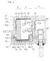
Patent Document 1 which is shown as an example in FIG. 4. This drawing shows an approximate half of the radial cross section of a short cylindrical gas generator. In this gas generator, a housing structure obtained by placing a two-cylinder-structuredupper vessel 51 with a double short-tube-structuredlower vessel 54 and subjecting them to friction welding (housing for the gas generator) is used as an ignition chamber P at the central space and used as a combustion chamber G and a filter chamber P at the annular space in the periphery. - A
squib 68 and anenhancer 69 are incorporated inside the ignition chamber P from below. Meanwhile, a concaved ring-shaped lid member 66 having a double flange on the cross section is fixed in the combustion chamber G and the filter chamber F by allowing each flange of 66d and 66e to respectively contact withburrs upper vessel 51, andgas generants 57 and a cooling/slag-collectingmember 60 are housed radially in sequence into an annular space sandwiched between thelid member 66 and theupper vessel 51, thereby forming the combustion chamber G and the filter chamber F. - Further, ring-
shaped cushion members upper face 70 and alower face 71 of the layer of thegas generants 57. In addition,seal members member 60. Moreover, analuminum foil 64 for closing agas discharging orifice 53a and analuminum foil 65 for closing a burningorifice 52a are attached. The above-described constitution makes it possible to provide a gas generator which can sufficiently withstand a rise in inner pressure due to gas generated inside the gas generation chamber G.
Patent Document 1: Japanese Published Unexamined Patent Application No. 9-207705 - However, as shown in FIG. 4, this kind of two-cylinder type gas generator is larger in the number of parts for constituting the gas generator and complicated in structure. Therefore, some limitations are imposed on reducing the manufacturing cost, while maintaining the safety of the gas generator.
- An object of the present invention is to provide a gas generator which can be simplified in structure and also maintain higher safety even when the number of components is reduced. Means for Solving the Problem and Effects of the Invention
- The present invention has the following several features for attaining the object. In the present invention, the following main features are provided solely or in combination with other parts, whenever necessary.
- The gas generator of the present invention is provided with a housing, gas generants, a filter member and an igniter.
The housing is a metal housing constituted by an initiator shell and a closure shell. A combustion chamber is formed inside the housing. The gas generants are loaded into the combustion chamber, generating a high-temperature gas through combustion. A plurality of gas discharge openings are formed in the housing to discharge gas generated in the combustion chamber.
The filter member is disposed around the combustion chamber. The igniter is fitted to the housing to ignite and burn the gas generants in the combustion chamber. - Either or both of the initiator shell and the closure shell constituting the housing are provided with semi-spherical or semi-oval end plate portions and cylindrical portions having a diameter D formed continuously from the end plate portions. The ratio of H/D which is a ratio of the bottom distance H between the end plate portion of the initiator shell and that of the closure shell to the diameter D of the cylindrical portions is in the range from 0.4 to 1.3.
The above-described constitution makes it possible to reduce the number of parts and simplify the structure, thereby making the gas generator smaller in size and significantly reducing the manufacturing cost. Further, even if the gas generator is small in the number of parts and simplified in structure, the housing is prevented from deformation resulting from a rise in the pressure inside the housing due to gas generated through burning of the gas generants inside the combustion chamber. Further, a plurality of gas discharge openings are provided, by which a high-temperature gas discharged from the combustion chamber can stably be supplied. - A/At, which is a ratio of the total sum A of surface areas of the gas generants to the total sum At of opening areas of the gas discharge openings is in the range from 1300 to 2000.
Where the ratio of A/At is out of the above range, gas generants to be used may hardly be burnt. Further, where the ratio is in excess of 2000, the gas generator must be increased in strength, resulting in an increase in cost and weight, which is unfavorable in manufacturing the gas generator or in other aspects. - It is preferable that the gas discharge openings are available in two or more opening diameters.
It is preferable that the gas discharge openings are disposed in a single array or in a plurality of arrays.
It is preferable that the gas discharge openings are available in two different opening diameters (small and large), disposed in two arrays in a zigzag form, and D1/D2, which is a ratio of a small opening diameter D1 of the gas discharge opening to a large opening diameter D2 of the gas discharge opening is in the range from 0.1 to 1.0.
It is preferable that a distance between gas discharge openings d in an axial direction of the housing is related to the small opening diameter D1 and the large opening diameter D2 as follows where the gas discharge openings are disposed in two arrays in a zigzag form.
d≥ (D1+D2) /2
- It is preferable that the gas discharge openings are closed by a rupture member and the rupture member is a metal plate. The metal includes aluminum, steel or stainless steel.
It is preferable that the rupture member is in the range from 0.01mm to 0.3mm in thickness.
It is preferable that the rupture member is provided so as to be different in strength depending on an opening diameter of the gas discharge openings and the strength of the rupture member is increased with a decrease in diameter of the gas discharge openings. - On the assumption that the strength of the rupture member is increased with a decrease in diameter of the gas discharge openings, T1/T2 = D2/D1 is obtained when the strength of the rupture member is indicated by the ratio of the opening diameters, where
T1 is the strength of the rupture member which is attached to a gas discharge opening having a small diameter D1,
T2 is the strength of the rupture member which is attached to a gas discharge opening having a large diameter D2.
In this instance, it is preferable that with regard to the strength of the rupture member each of which is attached to a plurality of gas discharge openings having a different opening diameter, the strength of the rupture member is adjusted in such a way that T1/T2 = D2/D1 is in the range from 2 to 8. Best Mode for Carrying Out the Invention - Hereinafter, an explanation will be made for embodiments of the gas generator in the present invention with reference to the drawings.
FIG. 1 is a cross-sectional view of thegas generator 30, which is an example of the gas generator of the present invention. In FIG. 1, thegas generator 30 is to inflate and deploy an airbag and is provided with ahousing 3, gas generants 4, afilter member 6 and anigniter 7. - The
housing 3 is a metal housing constituted by aninitiator shell 1 and aclosure shell 2 . The metal includes iron, stainless steel, aluminum and steel. Acombustion chamber 5 is formed inside thehousing 3. The gas generants 4 are loaded into thecombustion chamber 5, generating a high-temperature gas through combustion. A plurality ofgas discharge openings housing 3 to discharge gas generated in thecombustion chamber 5.
Thefilter member 6 is disposed around thecombustion chamber 5. Theigniter 7 is fitted to thehousing 3 to ignite and burn the gas generants 4 in thecombustion chamber 5. - The
closure shell 2 is constituted by acylindrical portion 9 having diameter D, a semi-sphericalend plate portion 10 continuously formed from thecylindrical portion 9 and aflange portion 12 extending externally from thecylindrical portion 9. It is preferable that theinitiator shell 1 and theclosure shell 2 are in the range from 1.5mm to 3mm in thickness.
Further, in thehousing 3 formed by joining theinitiator shell 1 with theclosure shell 2, H/D, which is a ratio of the bottom distance H between theend plate portion 14 of theinitiator shell closure shell 2 of the diameter D of thecylindrical portions - Where the above-described ratio of H/D is less than 0.4, the gas generator may not be assembled due to structural features. Where it exceeds 1.3, it approaches the cylindrical-type gas generators in structure. Therefore, setting the ratio within the above-described range can make the gas generator small in size and also provide strength sufficient in withstanding the pressure due to the gas generated inside the
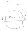
combustion chamber 5. - As shown in FIG. 2, it is preferable that a plurality of
gas discharge openings cylindrical portion 9 in a zigzag form. It is also preferable that they are formed in two arrays in a zigzag form. Since thegas discharge openings housing 3 is discharged without concentration, thereby preventing damage of afilter member 6. Further, thefilter member 6 can be used in a wider area to make an effective use of thefilter member 6. Thesegas discharge openings - Further, in these
gas discharge openings gas discharge openings - The
gas discharge openings gas discharge opening 8b is in the range from 0.1 to 1.0, preferably from 0.2 to 0.8, more preferably from 0.3 to 0.6. These twodifferent openings - Further, regarding the distance between the above-described two-different sized (small and large)
gas discharge openings housing 3 is related to the small opening diameter D1 and the large opening diameter D2 as follows.
d≥ (D1+D2) /2
Therefore, as described above, the gas generated inside thehousing 3 is discharged without concentration, thereby securely preventing damage of afilter member 6. Further, thefilter member 6 can be used in a wider area to make an effective use of thefilter member 6. - In addition, as shown in FIG. 1, these two different-sized (small and large)
gas discharge openings tape rupture member 11 which is made of band-form aluminum, steel, stainless steel, etc., and attached inside acylindrical portion 9, by which a space inside thecombustion chamber 5 is sealed. The height h of thecylindrical portion 9 is preferably 5mm or more, more preferably in the range from 5mm to 30mm and in particular preferably from 10mm to 30mm. Therefore, a band-form tape can be used as therupture member 11 and also therupture member 11 can be easily and securely attached thereto. - Therefore, the
rupture member 11 is preferably in the range from 0.01mm to 0.3mm in thickness. Further, it is provided so as to be different in strength depending on the diameter of the two different-sized (small and large)gas discharge openings rupture member 11 is increased in strength with a decrease in diameter of the gas discharge openings. - On the assumption that the strength of the rupture member is increased with a decrease in diameter of the gas discharge openings, T1/T2 = D2/D1 can be obtained when the strength of the rupture member is indicated by the ratio of the opening diameter, where
T1 is the strength of the rupture member which is attached to a gas discharge opening having a small diameter D1,
T2 is the strength of the rupture member which is attached to a gas discharge opening having a large diameter D2. - In this instance, it is preferable that with regard to the strength of the
rupture member 11 each of which is attached to a plurality ofgas discharge openings rupture member 11 is adjusted in such a way that T1/T2 = D2/D1 is in the range from 2 to 8, preferably from 2.5 to 7 and more preferably from 3 to 5.
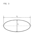
As explained above, therupture member 11 is attached, with the strength adjusted according to the diameter of thegas discharge openings - As shown in FIG. 3, d1/d2 which is a ratio of the short axis d1 of the
end plate portion 10 to the long axis d2 is preferably in a range from 1 to 0.02 and more preferably from 1 to 0.1. Where the ratio is in the above range, the gas generator makes it possible to sufficiently withstand an inner pressure resulting from the gas generated inside the gas generator. Further, theend plate portion 10 is available in a semi-spherical shape having a curvature radius R and the ratio of the diameter D of thecylindrical portion 9 to the curvature radius R is preferably in the range from 0.3 to 2 and more preferably from 0.9 to 2.
Therefore, the gas generator is made small in size. As explained above, the end plate portion is available in a semi-spherical shape or a semi-oval shape, thereby making it possible to remove a part on which pressure of the gas generated in thecombustion chamber 5 concentrates. Therefore, the gas generator can be constituted in a smaller number of parts, rendering the deformation of the housing to a minimum during gas generation, even if simply constructed. - As with the above-described
closure shell 2, theinitiator shell 1 which is joined to theclosure shell 2 by pressure contact or welding is constituted by acylindrical portion 13 and a semi-sphericalend plate portion 14 formed continuously from thecylindrical portion 13. Then, anigniter 7 is provided at the center of theend plate portion 14. - As with the
end plate portion 10 of theclosure shell 2, in theend plate portion 14 of theinitiator shell 1, d1/d2 which is a ratio of the short axis d1 to the long axis d2 is preferably in the range from 1 to 0.02 and more preferably from 1 to 0.1. Therefore, when theinitiator shell 1 is joined with theclosure shell 2 in an integral form, it makes it possible to form an approximately spherical or an approximatelyoval housing 3. - As shown in FIG. 1, an
igniter 7 provided at the center of theend plate portion 14 is constituted by a closed-end innercylindrical body 16 having a plurality ofenhancer openings 15 in the periphery, anenhancer 17 loaded into the innercylindrical body 16 and asquib 18 mounted so as to be in contact with theenhancer 17. - The inner
cylindrical body 16 is fixed to anigniter holder 19 by crimping or any other appropriate method. Then, the innercylindrical body 16 is fixed to theinitiator shell 1 through fixture of theigniter holder 19 to theend plate portion 14 by welding or any other appropriate method. Further, the innercylindrical body 16 is in a long-cylindrical shape extending from one end of thecombustion chamber 5 formed inside thehousing 3 to an approximate center of thecombustion chamber 5. A plurality ofenhancer openings 15 are formed in the periphery in a long-opening shape along the axial direction of the innercylindrical body 16. Theseenhancer openings 15 are formed in a zigzag form so that those disposed adjacent to each other along the axial direction of the innercylindrical body 16 are not provided in parallel as shown in FIG. 1. Therefore, a heat current spouted from theigniter 7 is effectively spouted into the whole part of thecombustion chamber 5. Further, theseenhancer openings 15 may be available in a round-opening shape, in addition to the long-opening shape. They do not need to be provided in a zigzag form. - A
filter member 6 disposed around thecombustion chamber 5 is provided along the inner wall of thecylindrical portions housing 3 constituted by theclosure shell 2 and theinitiator shell 1. Thefilter member 6, for example, is manufactured inexpensively by forming annularly bulk materials of metal wires or metal windings such as plain stitch wire netting, square-weave wire netting and crimped wire netting. Thefilter member 6 is pressed to the inner wall side of thehousing 3 bypresser members end plate portions closure shell 2 and theinitiator shell 1. - Gas generants 4 are loaded into an inner circumference of the
filter member 6. Then, these gas generants 4 are burnt by a heat current from theigniter 7 in thecombustion chamber 5 - The gas generants 4 loaded into the
combustion chamber 5 are non-azide compositions, and those made of fuels, oxidizers and additives (binder, slag-forming agent and combustion-adjusting agent) may be used. - Fuels include, for example, nitrogen-containing compounds. Nitrogen-containing compounds include one or more types of mixtures selected from triazole derivatives, tetrazole derivatives, guanidine derivatives, azodicarbors amide derivatives, hydrazine derivatives, urea derivatives and ammine complexes.
- Triazole derivatives include, for example, 5-oxo-1,2,4-triazole and amino triazole. Tetrazole derivativesinclude,for example,tetrazole,5-aminotetrazole, aminotetrazole nitrate, nitroaminotetrazole, 5,5'-bi-1H-tetrazole, 5,5'-bi-1H-tetrazole diammonium salt, 5,5'-azotetrazole diguanidium salt.
- Guanidine derivatives include, for example, guanidine, nitroguanidine, cyanoguanidine, triaminoguanidine nitrate, guanidine nitrate, aminoguanidine nitrate and guanidine carbonate. Azodicarbonamide derivatives include, for example, azodicarbonamide. Hydrazine derivatives include, for example, carbohydrazide, carbohydrazide nitrate complex, dihydrazide oxalate and hydrazine nitrate complex. Urea derivatives include, for example, biurets. Ammine complexes include hexaammine copper complex, hexaammine cobalt complex, tetraammine copper complex and tetraammine zinc complex.
- Of these nitrogen-containing compounds, one or more types of compounds selected from tetrazole derivatives and guanidine derivatives are preferable, and nitroguanidine, guanidine nitrate, cyanoguanidine, 5-aminotetrazole, aminoguanidine nitrate and guanidine carbonate are particularly preferable.
- These nitrogen-containing compounds in the gas generants 4 are different in mixture ratio, depending on the number of carbon atoms, hydrogen atoms and other atoms to be oxidized in the molecular formulae, preferably in the range from 20% by weight to 70% by weight and in particular preferably in the range from 30% by weight to 60% by weight. Further, the nitrogen-containing compounds are different in absolute value of the mixture ratio, depending on types of oxidizer to be added to gas generants. However, the concentration of trace amount CO in generated gas will increase where an absolute value of the mixture ratio in the nitrogen-containing compounds is greater than a total oxidation theoretical amount. In contrast, the concentration of trace amount NOx in the generated gas will increase where an absolute value of the mixture ratio in the nitrogen-containing compounds is equal to or lower than a total oxidation theoretical amount. Therefore, most preferable is a range in which both of them are optimally balanced.
- Preferable oxidizers include those at least selected from one type of cation-containing nitrates, nitrites and perchlorates selected from alkaline metals, alkaline earth metals, transition metals and ammonium. Also usable are oxidizers other than nitrates, namely, nitrites and perchlorates which are frequently used in an airbag inflator field. However, they will decrease in number of oxygen in nitrite molecules as compared with nitrate molecules or may reduce the production of fine powder mist easily discharged outside the bag, and therefore nitrates are preferable. Nitrates include, for example, sodium nitrate, potassium nitrate, magnesium nitrate, strontium nitrate, phase stable ammonium nitrate and basic copper nitrate. Preferable are strontium nitrate, phase stable ammonium nitrate and basic copper nitrate.
- A mixture ratio of oxidizers in the gas generants 4 is different in absolute value, depending on types and quantities of nitrogen-containing compounds to be used, and preferably in the range from 30% by weight to 80% by weight. The ratio is in particular preferably in the range from 40% by weight to 75% by weight, taking into consideration the concentrations of the above-described CO and NOx.
- Any binders may be usable as an additive as long as they do not significantly affect a combustion behavior of gas generants. Binders include, for example, organic binders such as metallic salts of carboxymethylcellulose, methylcellulose, hydroxyethylcellulose, cellulose acetate, cellulose propionate, cellulose acetate butyrate, nitrocellulose, microcrystalline cellulose, guar gum, polyvinyl alcohol, polyacrylamide, polysaccharide derivatives (e.g., starch) and stearate as well as inorganic binders such as molybdenum disulfide, synthetic hydroxytalcite, acid clay, talc, bentonite, diatomaceous earth, kaolin, silica and alumina.
- A mixture ratio of binders is preferably in the range from 0% by weight to 10% by weight for press molding and from 2% by weight to 15% by weight for extrusion molding. Molded articles will increase in breaking strength with an increase in an added quantity of binders. However, when the number of carbon atoms and hydrogen atoms in compositions is increased and the concentration of trace amount CO gas which is an incomplete combustion product of carbon atom is elevated, the quality of generated gas is affected. It is preferable to use binders in a minimum quantity because they may inhibit burning of gas generants. In particular a quantity of binders exceeding 15% by weight may require a relatively larger quantity of oxidizers to reduce a relative percentage of fuels, thereby making it difficult to provide a practicable gas generator system.
- Further, slag-forming agents may be added as compositions other than binders. Slag-forming agents are added to facilitate filtration of a
filter member 6 inside thegas generator 30 through interactions with metallic oxides in particular coming from oxidizer compositions in gas generants. - Slag-forming agents include natural clays mainly made with alumino silicate such as silicon nitride, silicon carbide, acid clay, silica, bentonite and kaolin, synthetic clays such as synthetic mica, synthetic kaolinite and synthetic smectite and those selected from talc which is a type of hydrous magnesium silicate mineral, etc. Of these materials, acid clay and silica are preferable and acid clay is particularly preferable. A mixture ratio of slag-forming agents is preferably in the range from 0% by weight to 20% by weight and particularly preferably from 2% by weight to 10% by weight. An excessively large quantity of agents will reduce the linear burning velocity or gas generation efficiency, while an excessively small quantity will not provide a full slag-forming function.
- Preferable combinations of gas generants 4 are gas generants which contain 5-aminotetrazole, strontium nitrate, synthetic hydrotalcite and silicon nitride, and those which contain guanidine nitrate, strontium nitrate, basic copper nitrate and acid clay.
- Combustion-adjusting agents may also be added, whenever necessary. Combustian-adjusting agents include explosive compounds such as metallic oxide, ferrosilicon, activated carbon, graphite, hexogen, octogen and 5-oxo-3-nitro-1,2,4-triazole. A mixture ratio of combustion-adjusting agents is preferably in the range from 0% by weight to 20% by weight, and particularly preferably from 2% by weight to 10% by weight. An excessively large quantity of agents will reduce the gas generation efficiency, while an excessively small quantity will not provide a sufficient burning velocity.
- The above-described gas generants 4 are preferably molded articles by press molding or extrusion molding and most preferably by extrusion molding. They may be available, for example, in the shape of a pellet (corresponding to one form of tablets generally found in drugs), circular column, tube, disk or hollow body with both ends closed. The tubular shape includes a cylindrical shape, and the cylindrical shape includes a single-pore cylindrical shape and a porous cylindrical shape. The hollow body shape with both ends closed includes a cylindrical shape with both ends closed. Further a state in which molded articles of gas generants 4 with both ends closed means a state in which pores opened at both ends are closed by two forces coming from the outside to the inside. The pores may be available either in a completely closed state or an incompletely closed state.
- An explanation will be made for how to manufacture hollow-body-shaped gas generants 4 with both ends closed. The above-described non-azide based compositions made with a nitrogen-containing compound, an oxidizer, a slag-forming agent and a binder are at first mixed by using a V-type mixer, a ball mill, etc. Then, the resultant is mixed, with water or a solvent (for example, ethanol) added, to obtain a bulk ingredient in a wet state. In this instance, the wet state means a state having plasticity to some extent in which water or a solvent is contained preferably in the range from 10% by weight to 25% by weight and more preferably from 13% by weight to 18% by weight. Thereafter, the wet bulk ingredient is, as it is, processed by using an extruder (for example, that equipped with a dice or an inner hole pin at the exit) to obtain extrusion-molded hollow cylindrical molded articles, the outer diameter of which is preferably in the range from 1.4mm to 4mm and more preferably from 1. 5mm to 3.5mm and the inner diameter of which is preferably in the range from 0.3mm to 1.2mm and more preferably from 0.5mm to 1.2mm.
- Thereafter, the extrusion-molded hollow cylindrical molded articles are subjected to pressing treatment at a uniform interval to obtain cylindrical molded articles with both ends closed. Usually, the hollow cylindrical molded articles are subjected to pressing treatment at a uniform interval and then cut off by folding them at the respectively closed recesses. Thereafter, they are dried at two stages, namely, usually in the range from 50°C to 60°C for 4 hours to 10 hours and then, usually in the range from 105°C to 120°C for 6 hours to 10 hours, thereby making it possible to obtain cylindrical shaped gas generants which have a space therein, with the ends closed. The thus obtained gas generants are usually in the range from 1.5mm to 8mm in length, preferably from 1.5mm to 7mm and more preferably from 2mm 6.5mm.
- Further, the gas generants 4 are determined for linear burning velocity under constant pressure conditions. The determination is empirically performed according to the following Vielle's formula.
r=aPn
wherein r denotes linear burning velocity; a, constant number; P, pressure; n, pressure exponent. The pressure exponent of n denotes a slope obtained by logarithmic plotting of X axis pressure in relation to the exponent of Y axis burning velocity. - A linear burning velocity of the gas generants used in the gas generator of the present embodiment is preferably in the range from 3mm/second to 60mm/second under 70kgf/cm2 and more preferably from 5mm/second to 35mm/second. Further, the pressure exponent is preferably in the range of n = 0.90 or lower, more preferably n=0.75 or lower, further more preferably n=0.60 or lower, and particular preferably in the range from n=0.60 to n=0.30.
- General methods for determining the linear burning velocity include a strand burner method, a compact motor method and a sealed pressure vessel method. More specificically, a test piece obtained by coating a restrictor on the surface after being molded to a predetermined size by press molding is used to determine the burning velocity in a high-pressure vessel by a fuse cutting method, etc. In this instance, the linear burning velocity is determined by referring to the pressure inside the high pressure vessel as a variable and the pressure exponent is determined in accordance with Vielle's formula above.
- Since preferable gas generants are non-azide gas generants, rawmaterials used are less harmful to humans. Further, a proper selection of fuel components and oxidizer components can reduce the heating value per mole of generated gas, making the gas generator smaller in size and lighter in weight.
-
Enhancers 17 to be mounted into an innercylindrical body 16 include those in which the generally-available following compositions are contained. More specifically, they are metal powders such as B/KNO3, oxidizer-containing compositions, compositions which contain nitrogen-containing compounds/oxidizers/metal powders and compositions similar to the above-describedgas generants 11. The nitrogen-containing compounds include those which can be used as fuel components of the gas generants (such as aminotetrazole and guanidine nitrate). The oxidizers include, for example, nitrates such as potassium nitrate, sodium nitrate and strontium nitrate. - The metal powders include, for example, boron, magnesium, aluminum, magnalium (alloy of magnesium with aluminum), titanium, zirconium and tungsten. Preferable combinations are metal powders which contain 5-aminotetrazole, potassium nitrate and boron and those which contain guanidine nitrate, potassium nitrate and boron. Molding binders usable as gas generants may be contained in the range from 0% by weight to 10% by weight, whenever necessary.
- Further, the
enhancers 17 are available in the shape of a grain, granule, pellet (corresponding to a form of tablets generally found in drugs), circular column, tube or disk, etc. The tubular shape includes, for example, a cylindrical shape, and the cylindrical shape includes, for example, a single-pore cylindrical shape and a porous cylindrical shape. They are manufactured by powder mixture, granulation method (granulation by agitation, granulation by spray drying, extrusion granulation, rolling granulation and compression granulation) and tablet compression. - Further, a
cushion member 22 is provided at anend plate portion 10 of theclosure shell 2 on thecombustion chamber 5. Thecushion member 22 is made of, for example, ceramic fiber or silicon foam, acting to prevent breakage of the gas generants 4 loaded inside thecombustion chamber 5 such as cracks resulting from vibration. - The
gas generator 30 of the present embodiment is a single-cylinder type gas generator and mainly used as a gas generator for inflating an airbag for a front passenger seat of the automobile. A bottom distance H between theend plate portions igniter 7 of thegas generator 30 is connected to a connector on the automobile (not illustrated). The gas generator may also be used for a driver' s seat. A two-cylinder type gas generator can also be installed into an airbag module. - The gas generator of the present embodiment makes it possible to load the gas generants in a similar quantity as that used in a conventional gas generator, even when the gas generator is reduced in size and weight, generating the gas in a similar quantity as a conventional gas generator. The present gas generator can be made smaller in size and lighter in weight while maintaining gas generation in a similar quantity as that of a conventional gas generator, because the
end plate portions - As explained above, in an
airbag module 30 connected to the automobile, for example, where a collision sensor detects a collision of the automobile, a squib ignition circuit connected to anigniter 7 allows theigniter 7 to function (electrified ignition), thereby burning gas generants 4 in acombustion chamber 5 to generate a high-temperature gas. At this time, the pressure rises inside thecombustion chamber 5. However, since thehousing 3 is in an approximately spherical shape, it is sufficiently strong to withstand the pressure rise inside thecombustion chamber 5 and remarkably small in deformation. - Therefore, a high-temperature gas generated inside the
combustion chamber 5 is carried through afilter member 6 and discharged fromgas discharge openings rupture member 11. When the high-temperature gas is carried through thefilter member 6, the gas is cooled and residue is collected. Further, thefilter member 6 is provided substantially across thecombustion chamber 5, resulting in an effective use of thefilter member 6. It is, thus, possible to discharge the gas which is sufficiently cooled and from which residue is sufficiently collected. - In addition, the
gas discharge openings - (An example of manufacturing hollow-body shaped gas generants having both closed ends which are used in the gas generator of the present embodiment)
Ethanol 3% by weight andwater 13% by weight are added to a mixture of guanidine nitrate 43.5% by weight, strontium nitrate 25% by weight, basic copper nitrate 25% by weight, acid clay 2.5% by weight and polyacrylamide 4% by weight, and the resultant is mixed and kneaded to obtain a mixedmass, which is then extruded at a pressure of 8Mpa by using an extruder equipped with a dice having an inner diameter of 2mm and an inner hole pin having an outer diameter of 0.5mm at the exit. The thus prepared bar-like molded article is fed between molding gears, while taken up by using a feed belt, and provided with recesses at a space of 4.4mm by male teeth of the molding gear. The article is cut off by folding it at the recesses, dried for 8 hours at 55°C and further dried for 8 hours at 110°C to obtain gas generants. - The present invention has been described in the above-described preferred embodiments but is not restricted only thereto. It is to be understood that variations may be made without departing from the spirit and scope of the present invention.
-
- FIG. 1 is a cross-sectional view showing one example of the gas generator of the present embodiment.
- FIG. 2 is an outline drawing of the gas generator of the present embodiment.
- FIG. 3 is a drawing showing the short axis d1 and the long axis d2 at the end plate portion of the gas generator of the present embodiment.
- FIG. 4 is a cross-sectional view showing one example of a conventional two-cylinder type gas generator.
-
- D:
- Diameter
- H:
- Bottom distance
- h:
- Length of cylindrical portion
- d:
- Distance between openings
- D1:
- Small opening diameter
- D2 :
- Large opening diameter
- 1:
- Initiator shell
- 2:
- Closure shell
- 3:
- Housing
- 4:
- Gas generants
- 5:
- Combustion chamber
- 6:
- Filter member
- 7:
- Igniter
- 8a:
- Small-diameter gas discharge opening
- 8b:
- Large-diameter gas discharge opening
- 9:
- Cylindrical portion
- 10:
- End Plate portion
- 11:
- Rupture member
- 12:
- Flange portion
- 13:
- Cylindrical portion
- 14:
- End plate portion
- 15:
- Enhancer opening
- 16:
- Inner cylindrical body
- 17:
- Enhancer
- 18:
- Squib
- 19:
- Igniter holder
- 20,
- 21: Presser member
- 22:
- Cushion member
- 30:
- Gas generator
Claims (9)
1. A gas generator (30) comprising : a metal housing (3) constituted by an initiator shell (1) and a closure shell (2), a combustion chamber (5) which is formed inside the housing (3) and into which gas generants (4) generating a high-temperature gas through combustion are loaded, a filter member (6) disposed around the combustion chamber (5), an igniter (7) mounted into the housing (3) and igniting and burning the gas generants (4) inside the combustion chamber (5) and a plurality of gas discharge openings (8a, 8b) formed on the housing (3) and discharging the gas generated in the combustion chamber (5),
wherein either or both of the initiator shell (1) and the closure shell (2) constituting the housing (3) are provided with semi-spherical or semi-oval end plate portions (14, 10) and cylindrical portions (13, 9) having a diameter D continuously formed from these end plate portions (14, 10), H/D of a ratio of the bottom distance H between the end plate portion (14) of the initiator shell (1) and that (10) of the closure shell (2) to the diameter D of the cylindrical portions (13. 9) is in the range from 0.4 to 1.3 and (A/At) which is a ratio of the total sum (A) of the surface areas of gas generants (4) to the total sum (At) of the opening areas of the gas discharge openings (8a, 8b) is in excess of 1300 and not more than 2000.
wherein either or both of the initiator shell (1) and the closure shell (2) constituting the housing (3) are provided with semi-spherical or semi-oval end plate portions (14, 10) and cylindrical portions (13, 9) having a diameter D continuously formed from these end plate portions (14, 10), H/D of a ratio of the bottom distance H between the end plate portion (14) of the initiator shell (1) and that (10) of the closure shell (2) to the diameter D of the cylindrical portions (13. 9) is in the range from 0.4 to 1.3 and (A/At) which is a ratio of the total sum (A) of the surface areas of gas generants (4) to the total sum (At) of the opening areas of the gas discharge openings (8a, 8b) is in excess of 1300 and not more than 2000.
2. A gas generator according to Claim 1, wherein the gas discharge openings (8a, 8b) are available in two or more opening diameters.
3. A gas generator according to Claim 1, wherein the gas discharge openings (8a, 8b) are disposed in a single array or in a plurality of arrays.
4. A gas generator according to Claim 1, wherein the gas discharge openings (8a, 8b) are available in two opening diameters (large and small) and disposed in two arrays in a zigzag form, and D1/D2 which is a ratio of a small opening diameter D1 of the gas discharge opening to a large opening diameter D2 of the gas discharge opening is in the range from 0.1 to 1.0.
5. A gas generator according to Claim 4, wherein a distance between gas discharge openings (8a, 8b) d in an axial direction of the housing (3) is related to the small opening diameter D1 and the large opening diameter D2 as follows where the gas discharge openings (8a, 8b) are disposed in two arrays in a zigzag form.
d≥ (D1+D2) /2
d≥ (D1+D2) /2
6. A gas generator according to Claim 1, wherein the gas discharge openings (8a, 8b) are closed by a rupture member (11) and the rupture member (11) is a metal plate made of aluminum, steel or stainless steel.
7. A gas generator according to Claim 6, wherein the rupture member (11) is in the range from 0.01mm to 0.3mm in thickness.
8. A gas generator according to Claim 6, wherein the rupture member (11) is provided so as to be different in strength depending on an opening diameter of the gas discharge openings (8a, 8b) and the strength of the rupture member (11) is increased with a decrease in diameter of the gas discharge openings (8a, 8b).
9. A gas generator according to Claim 6, wherein with regard to the strength of the rupture member (11) each of which is attached to a plurality af gas discharge openings (8a, 8b) having a different opening diameter, the strength of the rupture member is adjusted in such a way that T1/T2 = D2/D1 is in the range from 2 to 8 on the assumption of T1/T2 = D2/D1,
where
T1 is the strength of the rupture member which is attached to a gas discharge opening having a small diameter D1,
T2 is the strength of the rupture member which is attached to a gas discharge opening having a large diameter D2.
where
T1 is the strength of the rupture member which is attached to a gas discharge opening having a small diameter D1,
T2 is the strength of the rupture member which is attached to a gas discharge opening having a large diameter D2.
Applications Claiming Priority (2)
| Application Number | Priority Date | Filing Date | Title |
|---|---|---|---|
| JP2003287407 | 2003-08-06 | ||
| PCT/JP2004/011339 WO2005014345A1 (en) | 2003-08-06 | 2004-08-06 | Gas producer |
Publications (1)
| Publication Number | Publication Date |
|---|---|
| EP1661775A1 true EP1661775A1 (en) | 2006-05-31 |
Family
ID=34131484
Family Applications (1)
| Application Number | Title | Priority Date | Filing Date |
|---|---|---|---|
| EP04771339A Withdrawn EP1661775A1 (en) | 2003-08-06 | 2004-08-06 | Gas producer |
Country Status (5)
| Country | Link |
|---|---|
| US (1) | US7398996B2 (en) |
| EP (1) | EP1661775A1 (en) |
| JP (1) | JP4490919B2 (en) |
| CN (1) | CN1863695A (en) |
| WO (1) | WO2005014345A1 (en) |
Cited By (2)
| Publication number | Priority date | Publication date | Assignee | Title |
|---|---|---|---|---|
| WO2011122511A1 (en) * | 2010-03-30 | 2011-10-06 | Daicel Chemical Industries, Ltd. | Gas generator having combustion chamber including cushion member |
| EP3366526A4 (en) * | 2015-10-23 | 2019-03-20 | Nippon Kayaku Kabushiki Kaisha | Gas generator |
Families Citing this family (27)
| Publication number | Priority date | Publication date | Assignee | Title |
|---|---|---|---|---|
| US20070057496A1 (en) * | 2005-06-08 | 2007-03-15 | Daicel Chemical Industries, Ltd. | Gas generator for air bag |
| JP4907931B2 (en) * | 2005-09-15 | 2012-04-04 | 日本化薬株式会社 | Gas generator |
| US20090020197A1 (en) * | 2007-07-16 | 2009-01-22 | Key Safety Systems, Inc. | Gas generating compositions and airbag inflators |
| EP3296162B1 (en) * | 2008-09-30 | 2019-11-06 | TRW Airbag Systems GmbH | Gas generator, method for the production thereof and module having a gas generator |
| US8839871B2 (en) | 2010-01-15 | 2014-09-23 | Halliburton Energy Services, Inc. | Well tools operable via thermal expansion resulting from reactive materials |
| US8474533B2 (en) * | 2010-12-07 | 2013-07-02 | Halliburton Energy Services, Inc. | Gas generator for pressurizing downhole samples |
| US9151138B2 (en) | 2011-08-29 | 2015-10-06 | Halliburton Energy Services, Inc. | Injection of fluid into selected ones of multiple zones with well tools selectively responsive to magnetic patterns |
| US9010442B2 (en) | 2011-08-29 | 2015-04-21 | Halliburton Energy Services, Inc. | Method of completing a multi-zone fracture stimulation treatment of a wellbore |
| US9506324B2 (en) | 2012-04-05 | 2016-11-29 | Halliburton Energy Services, Inc. | Well tools selectively responsive to magnetic patterns |
| US9073512B1 (en) * | 2012-07-23 | 2015-07-07 | Tk Holdings Inc. | Gas generating system with gas generant cushion |
| US9169705B2 (en) | 2012-10-25 | 2015-10-27 | Halliburton Energy Services, Inc. | Pressure relief-assisted packer |
| US8770621B1 (en) | 2013-02-26 | 2014-07-08 | Arc Automotive Inc. | Variable orifice construction |
| US9587486B2 (en) | 2013-02-28 | 2017-03-07 | Halliburton Energy Services, Inc. | Method and apparatus for magnetic pulse signature actuation |
| US9587487B2 (en) | 2013-03-12 | 2017-03-07 | Halliburton Energy Services, Inc. | Wellbore servicing tools, systems and methods utilizing near-field communication |
| US9284817B2 (en) | 2013-03-14 | 2016-03-15 | Halliburton Energy Services, Inc. | Dual magnetic sensor actuation assembly |
| US9752414B2 (en) | 2013-05-31 | 2017-09-05 | Halliburton Energy Services, Inc. | Wellbore servicing tools, systems and methods utilizing downhole wireless switches |
| US20150075770A1 (en) | 2013-05-31 | 2015-03-19 | Michael Linley Fripp | Wireless activation of wellbore tools |
| US9482072B2 (en) | 2013-07-23 | 2016-11-01 | Halliburton Energy Services, Inc. | Selective electrical activation of downhole tools |
| DK3097265T3 (en) | 2014-03-24 | 2020-02-17 | Halliburton Energy Services Inc | Well tools having magnetic shielding for magnetic sensor |
| EP3135543B2 (en) | 2014-04-25 | 2022-09-28 | Nippon Kayaku Kabushiki Kaisha | Gas generator |
| JP6265848B2 (en) * | 2014-07-01 | 2018-01-24 | 日本化薬株式会社 | Gas generator |
| WO2016085465A1 (en) | 2014-11-25 | 2016-06-02 | Halliburton Energy Services, Inc. | Wireless activation of wellbore tools |
| CN108463379B (en) * | 2016-01-26 | 2021-02-12 | 株式会社大赛璐 | Gas generator |
| US10730474B2 (en) * | 2016-02-23 | 2020-08-04 | Nippon Kayaku Kabushiki Kaisha | Gas generator |
| JP6691442B2 (en) * | 2016-06-27 | 2020-04-28 | 株式会社ダイセル | Gas generator |
| DE102016213002B4 (en) * | 2016-07-15 | 2019-02-14 | Joyson Safety Systems Germany Gmbh | Gas generator for a gas bag module of a vehicle occupant restraint system and method for producing a gas generator |
| JP6910828B2 (en) | 2017-04-03 | 2021-07-28 | 日本化薬株式会社 | Gas generator |
Family Cites Families (14)
| Publication number | Priority date | Publication date | Assignee | Title |
|---|---|---|---|---|
| US5269561A (en) * | 1992-07-06 | 1993-12-14 | Morton International, Inc. | Vented gas passenger side air bag inflator |
| JPH09207705A (en) | 1995-11-28 | 1997-08-12 | Nippon Kayaku Co Ltd | Gas generator for air bag and its assembly method |
| US6032979C1 (en) * | 1998-02-18 | 2001-10-16 | Autoliv Asp Inc | Adaptive output inflator |
| EP1029749B1 (en) * | 1998-09-28 | 2004-08-18 | Daicel Chemical Industries, Ltd. | Ignition means for a gas generator |
| JP4278843B2 (en) * | 1999-07-28 | 2009-06-17 | 日本化薬株式会社 | Gas generator |
| TW469235B (en) * | 1999-10-04 | 2001-12-21 | Daicel Chem | Gas generator for air bag and air bag device |
| TW527294B (en) * | 1999-11-29 | 2003-04-11 | Daicel Chem | Gas generator for air bag and devices for the same |
| US6189927B1 (en) * | 1999-12-16 | 2001-02-20 | Autoliv Asp, Inc. | Adaptive output inflator |
| JP4860807B2 (en) * | 2000-06-12 | 2012-01-25 | 株式会社ダイセル | Gas generator for multistage airbag |
| US6527297B1 (en) * | 2000-08-30 | 2003-03-04 | Autoliv Asp, Inc. | Inflator device ignition of gas generant |
| US6860510B2 (en) * | 2001-08-21 | 2005-03-01 | Daicel Chemical Industries, Ltd. | Multistage inflating-type hybrid inflator |
| KR100621132B1 (en) * | 2002-02-06 | 2006-09-13 | 니폰 가야꾸 가부시끼가이샤 | Gas generator |
| US6886856B2 (en) * | 2003-04-01 | 2005-05-03 | Key Safety Systems, Inc. | Dual stage inflator |
| JP4180993B2 (en) * | 2003-08-06 | 2008-11-12 | 日本化薬株式会社 | Gas generator |
-
2004
- 2004-08-06 US US10/567,035 patent/US7398996B2/en not_active Expired - Fee Related
- 2004-08-06 CN CNA2004800291815A patent/CN1863695A/en active Pending
- 2004-08-06 JP JP2005512966A patent/JP4490919B2/en active Active
- 2004-08-06 EP EP04771339A patent/EP1661775A1/en not_active Withdrawn
- 2004-08-06 WO PCT/JP2004/011339 patent/WO2005014345A1/en active Application Filing
Non-Patent Citations (1)
| Title |
|---|
| See references of WO2005014345A1 * |
Cited By (4)
| Publication number | Priority date | Publication date | Assignee | Title |
|---|---|---|---|---|
| WO2011122511A1 (en) * | 2010-03-30 | 2011-10-06 | Daicel Chemical Industries, Ltd. | Gas generator having combustion chamber including cushion member |
| US8590929B2 (en) | 2010-03-30 | 2013-11-26 | Daicel Chemical Industries, Ltd. | Gas generator having combustion chamber including cushion member |
| EP3366526A4 (en) * | 2015-10-23 | 2019-03-20 | Nippon Kayaku Kabushiki Kaisha | Gas generator |
| US10759377B2 (en) | 2015-10-23 | 2020-09-01 | Nippon Kayaku Kabushiki Kaisha | Gas generator |
Also Published As
| Publication number | Publication date |
|---|---|
| CN1863695A (en) | 2006-11-15 |
| US20070039508A1 (en) | 2007-02-22 |
| US7398996B2 (en) | 2008-07-15 |
| WO2005014345A1 (en) | 2005-02-17 |
| JPWO2005014345A1 (en) | 2007-09-27 |
| JP4490919B2 (en) | 2010-06-30 |
Similar Documents
| Publication | Publication Date | Title |
|---|---|---|
| US7398996B2 (en) | Gas producer | |
| JP4136944B2 (en) | Gas generator | |
| US20070063494A1 (en) | Gas producer | |
| US7721652B2 (en) | Gas generator | |
| US6096147A (en) | Ignition enhanced gas generant and method | |
| JP4257740B2 (en) | Gas generator | |
| US6851374B1 (en) | Dual stage inflator for low melting gas generants | |
| US20070063495A1 (en) | Installation structure of gas producer and air bag module | |
| WO2000018619A1 (en) | Molded body of composition of gas generating agent for air bags | |
| JP4593944B2 (en) | Gas generator for airbag | |
| WO2005123631A1 (en) | Firing agent for gas generating device | |
| JP4514024B2 (en) | Gunpowder molded body and gas generator having the same | |
| JP5391440B2 (en) | Pyro-type gas generator and molded article of gas generating agent composition | |
| JP2005313752A (en) | Gas producer | |
| JP2960388B2 (en) | Molded product of gas generating composition for airbag | |
| WO2004080767A1 (en) | Gas generator | |
| JP2001206189A (en) | Gas generator for air bag and air bag device | |
| JP2005067520A (en) | Gas generator | |
| JP4891942B2 (en) | Gas generator | |
| JPH10182275A (en) | Gas generator for air bag and air bag device provided with the same | |
| JP2000026189A (en) | Formed body of gas generating agent composition for air bag |
Legal Events
| Date | Code | Title | Description |
|---|---|---|---|
| PUAI | Public reference made under article 153(3) epc to a published international application that has entered the european phase |
Free format text: ORIGINAL CODE: 0009012 |
|
| 17P | Request for examination filed |
Effective date: 20060306 |
|
| AK | Designated contracting states |
Kind code of ref document: A1 Designated state(s): AT BE BG CH CY CZ DE DK EE ES FI FR GB GR HU IE IT LI LU MC NL PL PT RO SE SI SK TR |
|
| DAX | Request for extension of the european patent (deleted) | ||
| STAA | Information on the status of an ep patent application or granted ep patent |
Free format text: STATUS: THE APPLICATION IS DEEMED TO BE WITHDRAWN |
|
| 18D | Application deemed to be withdrawn |
Effective date: 20100407 |