EP1665986B1 - Blood collection set with an expanded internal volume - Google Patents
Blood collection set with an expanded internal volume Download PDFInfo
- Publication number
- EP1665986B1 EP1665986B1 EP05111371A EP05111371A EP1665986B1 EP 1665986 B1 EP1665986 B1 EP 1665986B1 EP 05111371 A EP05111371 A EP 05111371A EP 05111371 A EP05111371 A EP 05111371A EP 1665986 B1 EP1665986 B1 EP 1665986B1
- Authority
- EP
- European Patent Office
- Prior art keywords
- hub
- internal chamber
- blood collection
- passage
- cannula
- Prior art date
- Legal status (The legal status is an assumption and is not a legal conclusion. Google has not performed a legal analysis and makes no representation as to the accuracy of the status listed.)
- Active
Links
- 239000008280 blood Substances 0.000 title claims description 97
- 210000004369 blood Anatomy 0.000 title claims description 97
- 239000012530 fluid Substances 0.000 claims description 30
- 238000004891 communication Methods 0.000 claims description 15
- 230000017531 blood circulation Effects 0.000 claims description 10
- 239000003570 air Substances 0.000 description 21
- 210000004204 blood vessel Anatomy 0.000 description 10
- 229920003023 plastic Polymers 0.000 description 9
- 239000004033 plastic Substances 0.000 description 8
- 238000004806 packaging method and process Methods 0.000 description 7
- 238000013461 design Methods 0.000 description 6
- 229920002457 flexible plastic Polymers 0.000 description 6
- 238000012800 visualization Methods 0.000 description 5
- 239000012080 ambient air Substances 0.000 description 3
- 210000005224 forefinger Anatomy 0.000 description 3
- 239000000463 material Substances 0.000 description 3
- 230000007246 mechanism Effects 0.000 description 3
- 238000007789 sealing Methods 0.000 description 3
- 210000003813 thumb Anatomy 0.000 description 3
- 230000012953 feeding on blood of other organism Effects 0.000 description 2
- 230000013011 mating Effects 0.000 description 2
- 238000000034 method Methods 0.000 description 2
- 230000004044 response Effects 0.000 description 2
- 238000013022 venting Methods 0.000 description 2
- 230000004872 arterial blood pressure Effects 0.000 description 1
- 230000000903 blocking effect Effects 0.000 description 1
- 230000036772 blood pressure Effects 0.000 description 1
- 230000003111 delayed effect Effects 0.000 description 1
- 229920001971 elastomer Polymers 0.000 description 1
- 239000000806 elastomer Substances 0.000 description 1
- 238000001802 infusion Methods 0.000 description 1
- 208000014674 injury Diseases 0.000 description 1
- 230000007774 longterm Effects 0.000 description 1
- 229920000642 polymer Polymers 0.000 description 1
- 230000001681 protective effect Effects 0.000 description 1
- 230000001012 protector Effects 0.000 description 1
- 238000010992 reflux Methods 0.000 description 1
- 229920001169 thermoplastic Polymers 0.000 description 1
- 239000004416 thermosoftening plastic Substances 0.000 description 1
- 230000008733 trauma Effects 0.000 description 1
Images


Classifications
-
- A—HUMAN NECESSITIES
- A61—MEDICAL OR VETERINARY SCIENCE; HYGIENE
- A61B—DIAGNOSIS; SURGERY; IDENTIFICATION
- A61B5/00—Measuring for diagnostic purposes; Identification of persons
- A61B5/15—Devices for taking samples of blood
- A61B5/153—Devices specially adapted for taking samples of venous or arterial blood, e.g. with syringes
- A61B5/154—Devices using pre-evacuated means
- A61B5/1545—Devices using pre-evacuated means comprising means for indicating vein or arterial entry
-
- A—HUMAN NECESSITIES
- A61—MEDICAL OR VETERINARY SCIENCE; HYGIENE
- A61B—DIAGNOSIS; SURGERY; IDENTIFICATION
- A61B5/00—Measuring for diagnostic purposes; Identification of persons
- A61B5/15—Devices for taking samples of blood
- A61B5/150007—Details
- A61B5/150015—Source of blood
- A61B5/15003—Source of blood for venous or arterial blood
-
- A—HUMAN NECESSITIES
- A61—MEDICAL OR VETERINARY SCIENCE; HYGIENE
- A61B—DIAGNOSIS; SURGERY; IDENTIFICATION
- A61B5/00—Measuring for diagnostic purposes; Identification of persons
- A61B5/15—Devices for taking samples of blood
- A61B5/150007—Details
- A61B5/150206—Construction or design features not otherwise provided for; manufacturing or production; packages; sterilisation of piercing element, piercing device or sampling device
- A61B5/150213—Venting means
-
- A—HUMAN NECESSITIES
- A61—MEDICAL OR VETERINARY SCIENCE; HYGIENE
- A61B—DIAGNOSIS; SURGERY; IDENTIFICATION
- A61B5/00—Measuring for diagnostic purposes; Identification of persons
- A61B5/15—Devices for taking samples of blood
- A61B5/150007—Details
- A61B5/150206—Construction or design features not otherwise provided for; manufacturing or production; packages; sterilisation of piercing element, piercing device or sampling device
- A61B5/150221—Valves
-
- A—HUMAN NECESSITIES
- A61—MEDICAL OR VETERINARY SCIENCE; HYGIENE
- A61B—DIAGNOSIS; SURGERY; IDENTIFICATION
- A61B5/00—Measuring for diagnostic purposes; Identification of persons
- A61B5/15—Devices for taking samples of blood
- A61B5/150007—Details
- A61B5/150374—Details of piercing elements or protective means for preventing accidental injuries by such piercing elements
- A61B5/150381—Design of piercing elements
- A61B5/150389—Hollow piercing elements, e.g. canulas, needles, for piercing the skin
-
- A—HUMAN NECESSITIES
- A61—MEDICAL OR VETERINARY SCIENCE; HYGIENE
- A61B—DIAGNOSIS; SURGERY; IDENTIFICATION
- A61B5/00—Measuring for diagnostic purposes; Identification of persons
- A61B5/15—Devices for taking samples of blood
- A61B5/150007—Details
- A61B5/150374—Details of piercing elements or protective means for preventing accidental injuries by such piercing elements
- A61B5/150381—Design of piercing elements
- A61B5/150503—Single-ended needles
-
- A—HUMAN NECESSITIES
- A61—MEDICAL OR VETERINARY SCIENCE; HYGIENE
- A61B—DIAGNOSIS; SURGERY; IDENTIFICATION
- A61B5/00—Measuring for diagnostic purposes; Identification of persons
- A61B5/15—Devices for taking samples of blood
- A61B5/150007—Details
- A61B5/150374—Details of piercing elements or protective means for preventing accidental injuries by such piercing elements
- A61B5/150534—Design of protective means for piercing elements for preventing accidental needle sticks, e.g. shields, caps, protectors, axially extensible sleeves, pivotable protective sleeves
- A61B5/150572—Pierceable protectors, e.g. shields, caps, sleeves or films, e.g. for hygienic purposes
-
- A—HUMAN NECESSITIES
- A61—MEDICAL OR VETERINARY SCIENCE; HYGIENE
- A61B—DIAGNOSIS; SURGERY; IDENTIFICATION
- A61B5/00—Measuring for diagnostic purposes; Identification of persons
- A61B5/15—Devices for taking samples of blood
- A61B5/150007—Details
- A61B5/15074—Needle sets comprising wings, e.g. butterfly type, for ease of handling
-
- A—HUMAN NECESSITIES
- A61—MEDICAL OR VETERINARY SCIENCE; HYGIENE
- A61B—DIAGNOSIS; SURGERY; IDENTIFICATION
- A61B5/00—Measuring for diagnostic purposes; Identification of persons
- A61B5/15—Devices for taking samples of blood
- A61B5/150992—Blood sampling from a fluid line external to a patient, such as a catheter line, combined with an infusion line; blood sampling from indwelling needle sets, e.g. sealable ports, luer couplings, valves
Definitions
- the subject invention relates to a blood collection set with an internal chamber, which increases the internal volume of the blood collection set thereby improving flash.
- a typical blood collection set includes an IV needle assembly with an IV cannula that has a proximal end, a sharply pointed distal end and a lumen extending between the ends.
- the needle assembly also includes a plastic IV hub with a proximal end, a distal end, and a passage extending between the ends.
- the proximal end of the IV cannula is mounted in the passage of the IV hub so that the lumen through the IV cannula communicates with the passage through the IV hub.
- the needle assembly may further include a shield for shielding the IV cannula after use (a so called safety blood collection set) and a packaging cover for safely covering the IV cannula prior to use.
- Packaging covers typically are rigid tubes with a proximal end that can be telescoped over the IV cannula and frictionally engaged with the distal end of the IV hub.
- Shields for shielding the IV cannula of blood collection sets have taken many forms. Some shields are telescoped over the IV hub and can be moved from a proximal position where the cannula is exposed to a distal position where the cannula is shielded. Other shields are hinged to the IV hub and can be rotated from an open position where the IV cannula is exposed to a closed position where the IV cannula is shielded.
- a needle assembly for a blood collection set also may include two flexible wings that project transversely from the IV hub or from the shield. The wings can be folded into face-to-face relationship with one another to effectively define a handle that facilitates manipulation of the needle assembly. The wings then can be rotated away from one another and held against the skin of the patient.
- Blood collection sets also include a length of flexible plastic tubing.
- the tubing has a distal end that is connected to the proximal end of the IV hub,
- the tubing also has a proximal end that is connected to a plastic fitting.
- the plastic fitting may be a female luer fitting that can be connected to a male luer fitting. The fitting then can be placed in communication with a reservoir or container for collecting a sample of blood.
- Evacuated tubes often are used with a tube holder that has a proximal end, a distal end, and a tubular side wall extending between the ends.
- the proximal end of the holder is widely open and is configured for slidably receiving the evacuated tube.
- the distal end of the holder typically includes an end wall with a mounting aperture.
- the mounting aperture includes internal threads or other mounting structures.
- the tube holder may be used with a non-patient needle assembly that has a non-patient hub with external surface configurations for mounting in the mounting aperture of the holder.
- the non-patient needle assembly further includes a non-patient cannula extending proximally from the hub and a multiple sample sleeve telescoped over the non-patient cannula and mounted to the proximal end of the hub.
- the hub of the non-patient needle assembly can be threaded or otherwise engaged in the mounting aperture of the tube holder so that the non-patient needle and the multiple sample sleeve project into the tube receiving chamber of the holder.
- the blood collection set may be used by mounting the fitting at the proximal end of the flexible plastic tubing to the distal end of the hub of the non-patient needle assembly.
- the packaging shield that covers the non-patient cannula then may be removed, and the hub of the non-patient needle assembly may be engaged with the tube holder.
- the medical practitioner then grips the IV needle assembly and removes the packaging cover from the IV cannula.
- the gripping of the IV needle assembly may include folding the flexible wings into face-to-face engagement and gripping the folded wings between a thumb and forefinger.
- the pointed distal end of the IV cannula then is urged into a targeted blood vessel.
- the wings then may be folded into engagement with the skin of the patient and may be taped in position.
- An evacuated tube then is urged into the open proximal end of the blood collection tube holder so that the non-patient needle pierces the stopper of the evacuated tube.
- the blood vessel of the patient is placed in communication with the interior of the evacuated tube, and the pressure differential between the blood vessel and the evacuated tube will generate a flow of blood through the IV cannula, through the passage of the IV hub, through the flexible tubing, through the non-patient hub and finally through the non-patient needle and into the evacuated tube.
- the translucent or opaque plastic material of blood collection sets and IV cannula shields, combined with numerous cannula shield mechanism components and the length of the typical needle hub tends to inhibit a clear indication of venous or arterial access.
- Blood flow into the plastic tubing does provide an indication of venous or arterial access (known as "flash") as the plastic tubing is often formed from a highly translucent or transparent plastic material.
- flash an indication of venous or arterial access
- the length of flash obtained from a typical venous entry may not be sufficient for blood flow to be observed in the flexible tubing at a location proximal to the IV needle assembly itself.
- a medical practitioner may have a delayed indication of venous or arterial access and may incorrectly assume that the blood vessel was not accessed properly. In these situations, the medical practitioner may try to access the blood vessel again even though the initial access was successful. Accordingly, the patient may be subjected to unnecessary trauma during a repeated attempt to access the targeted blood vessel.
- a blood collection set corresponding to the first part of claim 1 is disclosed in EP 1 442 705 Al.
- This blood collection set generally corresponds to Figs. 1A , 1B and Fig. 3 , but has in addition in the second hub a venting plug that permits an outflow of air while blocking an outflow of blood or other fluids.
- This venting mechanism enables air that had existed in interior portions of the blood collection set to be vented, and avoids the need to employ a discard tube.
- U.S. 6,261,263 B1 discloses a hub of an arterial punction needle having a tubular and transparent viewing chamber which is accessible to the reflux of blood.
- the viewing chamber is surrounding by a reserve chamber which is leaktight to ambient air and in air communication with an outlet end of the viewing chamber.
- WO 2004/062499 A1 discloses a flashback blood collection needle having an inlet cannula, an outlet cannula and a housing between both cannulae.
- the outlet cannula extends through a flashback chamber of the housing and the ends of the cannula are positioned adjacent to each other, wherein the outlet cannula extends through the flashback chamber.
- the blood collection set of the present invention is defined by claim 1.
- the invention relates to a blood collection set with an internal chamber provided to increase the internal volume of the blood collection set when compared to a prior art blood collection set which does not have an internal chamber. In this manner, improved flash visualization, can be provided.
- Internal chamber as used herein means an enclosed space or compartment, which is in communication with the fluid passage of the blood collection set.
- the "fluid passage” is defined as any part of the blood collection set in which blood flows and can include the lumen through the IV cannula, the passage through the IV hub, the passage through the flexible tubing, the passage through the non-patient hub and lumen through the non-patient cannula.
- Flash is defined as the initial blood flow into the fluid passage on venous entry, which provides an indication of venous or arterial access before an evacuated tube is urged into the open proximal end of the blood collection tube holder.
- Flash length is the linear distance that blood flows in a proximal direction along the fluid passage on venous entry.
- Flash volume is the volume of blood that flows into the fluid passage on venous entry expressed as a percentage of the total internal volume of the blood collection set.
- the blood collection set includes an IV needle assembly, a length of flexible plastic tubing extending from the IV needle assembly and a non-patient needle assembly.
- the internal chamber is advantageously disposed on or near the non-patient needle assembly to permit an increase in the internal volume of the blood collection set without being located directly in the blood flow path.
- the IV needle assembly typically comprises an IV hub having a proximal end, a distal end and a passage extending between the ends.
- the IV needle assembly typically further comprises an IV cannula having a proximal end mounted in the passage of the IV hub, a pointed distal end projecting distally from the IV hub and a lumen that communicates with the passage through the IV hub.
- the flexible tubing is typically connected to the proximal end of the IV hub.
- the IV needle assembly typically includes a packaging cover that protectively encloses the IV needle cannula prior to use. The packaging cover is removed immediately prior to use to permit access to the IV cannula.
- the IV needle assembly may further include a protective shield that is moveable relative to the IV cannula from an open position where the IV cannula is exposed to a closed position where the IV cannula is substantially shielded.
- the shield protects against accidental sticks with the used IV cannula.
- a pair of flexible wings may be mounted to the IV hub or to the shield to facilitate manipulation of the IV needle assembly.
- the non-patient needle assembly includes a non-patient hub having a proximal end and a distal end.
- the non-patient needle assembly further includes a non-patient cannula having a distal end securely mounted in the hub, a proximal end projecting proximally from the non-patient hub and a lumen that communicates with the passage through the non-patient hub.
- a multiple sample sleeve is typically mounted over the non-patient cannula and secured to the proximal end of the non-patient hub.
- External portions of the non-patient hub near the proximal end thereof may be formed with an array of external threads or other mounting structure to enable the non-patient needle assembly to be mounted to a collection tube holder or other such medical device.
- the holder may be pre-attached with the non-patient needle assembly.
- the blood collection set may further include a fitting mounted to the proximal end of the flexible plastic tubing and configured for mating with the distal end of the non-patient hub.
- the fitting may be a female luer fitting that can be engaged with the male luer taper at the distal end of the non-patient hub.
- the internal chamber is located in the non-patient assembly beyond the non-patient cannula proximal end, which means that the air passes through the non-patient cannula proximal end from which blood is drawn, and then into the internal chamber.
- air passes through the non-patient cannula proximal end from which blood is drawn, and then into the internal chamber.
- air is compressed and flows from the fluid passage and out of the non-patient cannula proximal end where it further flows through the space between needle exterior and multiple sample sleeve.
- the air then flows into the internal chamber, which may be at the non-patient barb, the non-patient hub thread, the non-patient hub body, or other location or combination of locations that are beyond the non-patient cannula proximal end.
- the collection tube which is applied at the non-patient cannula proximal end, draws blood from only the fluid passage and not from the internal chamber.
- a one-way check valve is located within the internal chamber.
- the valve allows air and blood to enter the internal chamber but shuts closed both when vacuum is applied.
- the tube draws blood from the fluid passage but not from the internal chamber, and upon removal of the IV needle from the targeted blood vessel, the check valve closes and inhibits blood from dripping from the IV needle tip.
- the internal chamber utilizes a branch in the fluid passage, e.g., a "Y" or "T".
- the branching may be at any location or locations along the fluid passage, but is advantageously at the proximal end such as at the non-patient hub.
- the branching may be in the form of a separate component added into the fluid passage such as in between the female and male luer fittings or it may be integral within the hub.
- the branching includes some type of internal chamber as discussed herein.
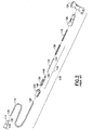
- a prior art blood collection set that contains IV cannula shielding is identified generally by the numeral 10 in FIGS. 1A and 1B .
- Blood collection set 10 is employed in this embodiment with a collection tube holder 12.
- Holder 12 has a proximal end 14, a distal end 16 and a tubular sidewall 18 extending between the ends.
- Proximal end 14 of holder 12 is widely open and defines an entry to a tube receptacle within sidewall 18.
- an evacuated collection tube can be slid in a proximal-to-distal direction through open proximal end 14 of holder 12 toward distal end 16.
- Distal end 16 of holder 12 is characterized by an end wall 20.
- End wall 20 is formed with an internally threaded mounting aperture 22, as shown in FIG. 3 .
- Blood collection set 10 includes an IV needle assembly 24 that comprises an IV hub 26.
- IV hub 26 includes a proximal end 28, a distal end 30 and a passage (not shown) extending between the ends.
- IV needle assembly 24 further includes an IV cannula 32 with a proximal end 34, a pointed distal end 36 and a lumen 38 extending between the ends.
- Proximal end 34 of IV cannula 32 is mounted securely in the passage of IV hub 26.
- lumen 38 through IV cannula 32 communicates with the passage through IV hub 26.
- Flexible wings 40 are mounted to IV hub 26 at a location near distal end 30.
- Wings 40 can be folded into face-to-face relationship with one another for convenient gripping between a thumb and forefinger to enable manipulation of IV needle assembly 24. Wings 40, however, also can be rotated into a substantially coplanar disposition for taping to the skin of a patient.
- IV needle assembly 24 further includes a tubular shield 42 that is telescoped over IV hub 26.
- Shield 42 is formed with transverse slots 44 that slidably receive wings 40.
- shield 42 can be slid from a proximal position, as shown in FIGS. 1A and 1B to a distal position.
- IV cannula 32 is exposed for use when shield 42 is in the proximal position shown in FIGS. 1A and 1B .
- IV cannula 32 is substantially surrounded by shield 42 when shield 42 is moved to the distal position.
- slots 44 in shield 42 are configured to lockingly engage wings 40 when shield 42 is in the distal position to prevent or complicate a re-exposure of IV cannula 32.
- FIGS. 1A and 1B is one of many optional shield designs that can be incorporated into blood collection set 10. Other designs may provide wings mounted directly to the shield. Still other designs may provide a hinged shield mounted to IV hub 26. In still other designs, a shield may be entirely separate from IV needle assembly 24.
- Fluid collection/infusion set 110 includes a length of flexible plastic tubing 112, a proximal fitting 114, a needle assembly 116, a spring 118 and a barrel assembly that comprises a front barrel 120, a rear barrel 122 and a wing 124.
- Needle assembly 116 includes a needle cannula 134, a needle hub 136 and a needle protector 138.
- Needle cannula 134 has a proximal end 140, a distal end 142 and a lumen 144 extending between the ends. Distal end 142 of needle cannula 134 is beveled to a sharp tip.
- FIGS. 1A and 1B also show that a blood collection set 10 further includes a length of flexible plastic tubing 46.
- Tubing 46 includes opposite proximal and distal ends 48 and 50 and a passage extending between the ends.
- Distal end 50 of tubing 46 is securely mounted to proximal end 28 of IV hub 26 so that the passage through IV hub 26 communicates with the passage through tubing 46.
- a female luer fitting 52 is securely mounted to proximal end 48 of tubing 46.
- Non-patient needle assembly 54 includes a non-patient hub 56 with a proximal end 58, a distal end 60 and a fluid passage 62 extending between the ends. Exterior surface regions of non-patient hub 56 substantially adjacent proximal end 58 define an array of external threads 64 configured for threaded engagement with the internal threads formed in mounting aperture 22 of collection tube holder 12. External surface regions of non-patient hub 56 adjacent distal end define a male luer taper 66 configured for mating with female luer fitting 52.
- Non-patient needle assembly 54 further includes a non-patient cannula 68 having a pointed proximal end 70, a distal end 72 and a lumen 74 extending between the ends. Distal end 72 of non-patient cannula 68 is mounted securely in passage 62 through non-patient hub 56 and aligns substantially with external threads 64 on non-patient hub 56.
- Non-patient needle assembly 54 further includes a multiple sample sleeve 76 mounted over non-patient cannula 68 and securely engaged with proximal end 58 of non-patient hub 56. Multiple sample sleeve 76 effectively functions as a valve that prevents a flow of fluid from non-patient cannula 68. However, multiple sample sleeve 76 can be pierced by pointed proximal end 70 of non-patient cannula 68 in response to forces generated by a stopper on an evacuated collection tube.
- flash visualization maybe acceptable in certain blood collection sets with safety features, such as the type shown in FIGS. 1A and 1B .
- the IV needle assembly and safety shield tend to be made from a translucent plastic material, and may only contain the IV cannula and flexible tubing, which may allow flash to be seen through the IV cannula hub walls. Therefore a minimum length of flash maybe sufficient, such that initial blood flow on venous entry maybe observed at the proximal end of the IV cannula.
- the length of flash obtained from a typical venous entry may not be sufficient for blood flow to be observed in the flexible tubing at a location proximal to the IV needle assembly itself, therefore flash visualization tends to be inhibited within the IV needle assembly.
- a blood collection set for example of the type disclosed above, contains an internal chamber that increases the internal volume of the blood collection set.
- the increase in internal volume of the blood collection set provides a greater length of flash and therefore improved flash visualization, such that, advantageously, blood is observed in the flexible tubing proximal the IV needle assembly on the initial venous entry. While such improved or lengthened flash is particularly advantageous for such complex blood collection sets as shown in FIG 2 , application in any blood collection set is contemplated.
- a blood collection set includes a plurality of internal spaces that will initially be at ambient air pressure. These internal spaces include the lumen through the IV cannula, the passage through the IV hub, the passage through the flexible tubing, the passage through the non-patient hub and lumen through the non-patient cannula.
- the blood collection set is employed by folding wings into face-to-face engagement with one another and gripping the wings between a thumb and forefinger. Any packaging cover that may be mounted over IV cannula then is removed and discarded. The pointed distal end of the IV cannula then is urged into a targeted blood vessel.
- the healthcare practitioner then may release the grip on the wings, and if long term access to the blood vessel is required, the wings may be taped into face-to-face engagement with the skin of the patient.
- the venous or arterial access achieved with the IV cannula places the plurality of interior spaces of the blood collection set in communication with the pressure of the blood in the patient. Blood pressure exceeds the ambient air pressure. Accordingly, the pressure of air in the above-referenced internal spaces will increase, and blood will begin to flow into these internal spaces.
- the system will reach equilibrium as the air pressure within the blood collection set increases in response to a reduction of volume caused by the inflow of blood.
- the system will include its original volume of air in the space between the proximal end of the non-patient needle and the blood that enters the blood collection set. This pressurized air will prevent any further flow of blood toward the non-patient assembly, thereby stopping flash.
- the total volume of the internal spaces maybe insufficient, such that flash maybe stopped before it can be observed.
- the internal chamber which lacks direct communication to the exterior, provides more internal volume into which the air can be pushed, allowing blood to push further into the device before the pressure of the blood equals the pressure of the air. This increase in interior space thereby allows a greater length of flash to occur.
- Various embodiments of such internal chambers are described in detail below.
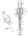
- FIGS. 4 and 5 show an embodiment of the invention, where the internal chamber 301 is located beyond the proximal end 370 of the non-patient cannula in the non-patient hub 356 and lacks direct communication to the exterior.
- the internal chamber 301 is annular in cross-section and has opposite proximal 770 and distal ends 771 and a wall 772 extending therebetween; the proximal end 770 has an inlet 777 in communication with the passage.
- the non-patient hub 356 is generally made from 2 separate parts; the male luer 374 and the non-patient thread assembly 375. Other configurations are possible.
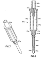
- FIGS 6 and 7 show another embodiment of the invention, with an elongated internal chamber to further increase the flash length.
- the internal chamber 301a is annular in cross-section and has opposite proximal 770a and distal ends 771a and a wall 772a extending therebetween, the proximal end 770a has an inlet 777a in communication with the passage.
- the non-patient hub is made from 2 separate parts; the male luer 374a and the non-patient thread assembly 375a.
- the longer internal chamber 301a is located beyond the proximal end 370a of the non-patient cannula in the non-patient thread assembly 375a and has no direct communication to the exterior. Other configurations are possible.
- FIGS 8 to 12 show a further embodiment of the invention, in which a one-way valve 555 is located within an internal chamber similar to that shown in FIG. 6 .
- the one way valve has a central core 550 surrounded by an annular flange 551 that has a sealing ring 552 around its outer diameter.
- the central core 550 is located around the non-patient needle exterior 368b within the internal chamber 301b and has a tapered base 553 which mates to the taper of inlet 777b.
- the one way valve 555 is formed from a resilient polymer such as an elastomer or thermoplastic.
- a vacuum is applied to the fluid passage, when an evacuated collection tube is applied at the non-patient needle tip.
- the resultant positive pressure differential between the internal chamber and the fluid passage causes the one way valve 555 to close, by the valve sealing ring 552 being pressed against the proximal end of the internal chamber 770b and the valve core tapered base 553 being pressed into inlet 777b thereby preventing outflow of air or blood from the internal chamber,.
- the one way valve is not limited to the particular design described in this embodiment as all types of one way valves can be contemplated for this invention.
- the one way valve 555 also inhibits blood from dripping from the IV needle tip upon removal of the IV needle from the targeted blood vessel after the blood collection has been completed.
- the fluid passage of the blood collection set will contain a reservoir of air and blood at venous pressure, which will be greater than the ambient atmospheric pressure.
- a back pressure is created within the fluid passage which may cause a back-flow of blood to drip from the IV needle tip.
- the reservoir of air at venous pressure is within the internal chamber 301b, therefore the back pressure causes the one way valve 555 to shut upon removal of the IV needle thereby preventing such a back-flow of blood in the fluid passage 362b.
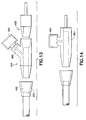
- FIGS 13 and 14 show another embodiment of an internal chamber 401 which is branched from the fluid passage using a "Y" or “T” branched internal chamber in the fluid passage into which air is displaced.
- the branching may be at any location or locations along the fluid passage, but is typically near the proximal end such as at the non-patient hub.
- FIG 13 shows a "Y” branched internal chamber 454 in the form of a separate component added into the fluid passage 462 such as in between the female 455 and male luer 456 fittings.
- FIG 14 shows a "T" branched internal chamber 457, which is an integral part of the non-patient hub, thus reducing the number of components.
- the use of a "Y” or “T” branched internal chamber may be accomplished with any convenient terminal shapes at the interfaces of each component.
- the embodiments exemplified previously are shown with luer tapered fittings but other interface designs such as direct connection to the flexible tubing may also be applied.
- typical applications use a three port "Y” or “T” branched internal chamber the use of a multiple port branched internal chamber system is also possible.
- the internal chamber 401 can be a separate component which is affixed into a port 460 of the branch system as shown in FIG 13 or an integral part of the branched system as shown in FIG 14 . All internal chamber geometries can also be contemplated.
Description
- The subject invention relates to a blood collection set with an internal chamber, which increases the internal volume of the blood collection set thereby improving flash.
- Phlebotomy procedures often are carried out using a blood collection set. A typical blood collection set includes an IV needle assembly with an IV cannula that has a proximal end, a sharply pointed distal end and a lumen extending between the ends. The needle assembly also includes a plastic IV hub with a proximal end, a distal end, and a passage extending between the ends. The proximal end of the IV cannula is mounted in the passage of the IV hub so that the lumen through the IV cannula communicates with the passage through the IV hub. The needle assembly may further include a shield for shielding the IV cannula after use (a so called safety blood collection set) and a packaging cover for safely covering the IV cannula prior to use. Packaging covers typically are rigid tubes with a proximal end that can be telescoped over the IV cannula and frictionally engaged with the distal end of the IV hub. Shields for shielding the IV cannula of blood collection sets have taken many forms. Some shields are telescoped over the IV hub and can be moved from a proximal position where the cannula is exposed to a distal position where the cannula is shielded. Other shields are hinged to the IV hub and can be rotated from an open position where the IV cannula is exposed to a closed position where the IV cannula is shielded. A needle assembly for a blood collection set also may include two flexible wings that project transversely from the IV hub or from the shield. The wings can be folded into face-to-face relationship with one another to effectively define a handle that facilitates manipulation of the needle assembly. The wings then can be rotated away from one another and held against the skin of the patient.
- Blood collection sets also include a length of flexible plastic tubing. The tubing has a distal end that is connected to the proximal end of the IV hub, The tubing also has a proximal end that is connected to a plastic fitting. Thus, fluid communication is provided between the lumen of the IV cannula and the plastic fitting at the proximal end of the flexible tubing. The plastic fitting may be a female luer fitting that can be connected to a male luer fitting. The fitting then can be placed in communication with a reservoir or container for collecting a sample of blood.
- Phlebotomy procedures often employ evacuated tubes, such as the VACUTAINER® brand of evacuated tubes sold by Becton Dickinson and Company. Evacuated tubes often are used with a tube holder that has a proximal end, a distal end, and a tubular side wall extending between the ends. The proximal end of the holder is widely open and is configured for slidably receiving the evacuated tube. The distal end of the holder typically includes an end wall with a mounting aperture. The mounting aperture includes internal threads or other mounting structures.
- The tube holder may be used with a non-patient needle assembly that has a non-patient hub with external surface configurations for mounting in the mounting aperture of the holder. The non-patient needle assembly further includes a non-patient cannula extending proximally from the hub and a multiple sample sleeve telescoped over the non-patient cannula and mounted to the proximal end of the hub. The hub of the non-patient needle assembly can be threaded or otherwise engaged in the mounting aperture of the tube holder so that the non-patient needle and the multiple sample sleeve project into the tube receiving chamber of the holder.
- The blood collection set may be used by mounting the fitting at the proximal end of the flexible plastic tubing to the distal end of the hub of the non-patient needle assembly. The packaging shield that covers the non-patient cannula then may be removed, and the hub of the non-patient needle assembly may be engaged with the tube holder. The medical practitioner then grips the IV needle assembly and removes the packaging cover from the IV cannula. The gripping of the IV needle assembly may include folding the flexible wings into face-to-face engagement and gripping the folded wings between a thumb and forefinger. The pointed distal end of the IV cannula then is urged into a targeted blood vessel. The wings then may be folded into engagement with the skin of the patient and may be taped in position. An evacuated tube then is urged into the open proximal end of the blood collection tube holder so that the non-patient needle pierces the stopper of the evacuated tube. As a result, the blood vessel of the patient is placed in communication with the interior of the evacuated tube, and the pressure differential between the blood vessel and the evacuated tube will generate a flow of blood through the IV cannula, through the passage of the IV hub, through the flexible tubing, through the non-patient hub and finally through the non-patient needle and into the evacuated tube.
- The translucent or opaque plastic material of blood collection sets and IV cannula shields, combined with numerous cannula shield mechanism components and the length of the typical needle hub tends to inhibit a clear indication of venous or arterial access. Blood flow into the plastic tubing does provide an indication of venous or arterial access (known as "flash") as the plastic tubing is often formed from a highly translucent or transparent plastic material. However, because of the existence of the elements associated with the IV needle assembly the length of flash obtained from a typical venous entry may not be sufficient for blood flow to be observed in the flexible tubing at a location proximal to the IV needle assembly itself. Thus, a medical practitioner may have a delayed indication of venous or arterial access and may incorrectly assume that the blood vessel was not accessed properly. In these situations, the medical practitioner may try to access the blood vessel again even though the initial access was successful. Accordingly, the patient may be subjected to unnecessary trauma during a repeated attempt to access the targeted blood vessel.
- A blood collection set corresponding to the first part of
claim 1 is disclosed inEP 1 442 705Figs. 1A ,1B andFig. 3 , but has in addition in the second hub a venting plug that permits an outflow of air while blocking an outflow of blood or other fluids. This venting mechanism enables air that had existed in interior portions of the blood collection set to be vented, and avoids the need to employ a discard tube. -
U.S. 6,261,263 B1 discloses a hub of an arterial punction needle having a tubular and transparent viewing chamber which is accessible to the reflux of blood. The viewing chamber is surrounding by a reserve chamber which is leaktight to ambient air and in air communication with an outlet end of the viewing chamber. -
WO 2004/062499 A1 discloses a flashback blood collection needle having an inlet cannula, an outlet cannula and a housing between both cannulae. The outlet cannula extends through a flashback chamber of the housing and the ends of the cannula are positioned adjacent to each other, wherein the outlet cannula extends through the flashback chamber. - It is an object of the invention to provide a blood collection set that increases the length of flash such that initial blood flow will be observable in the flexible tubing proximal the IV needle assembly and associated shielding elements.
- The blood collection set of the present invention is defined by
claim 1. - The invention relates to a blood collection set with an internal chamber provided to increase the internal volume of the blood collection set when compared to a prior art blood collection set which does not have an internal chamber. In this manner, improved flash visualization, can be provided.
- "Internal chamber" as used herein means an enclosed space or compartment, which is in communication with the fluid passage of the blood collection set. The "fluid passage" is defined as any part of the blood collection set in which blood flows and can include the lumen through the IV cannula, the passage through the IV hub, the passage through the flexible tubing, the passage through the non-patient hub and lumen through the non-patient cannula. "Flash" is defined as the initial blood flow into the fluid passage on venous entry, which provides an indication of venous or arterial access before an evacuated tube is urged into the open proximal end of the blood collection tube holder. "Flash length" is the linear distance that blood flows in a proximal direction along the fluid passage on venous entry. "Flash volume" is the volume of blood that flows into the fluid passage on venous entry expressed as a percentage of the total internal volume of the blood collection set.
- In one embodiment, the blood collection set includes an IV needle assembly, a length of flexible plastic tubing extending from the IV needle assembly and a non-patient needle assembly. The internal chamber is advantageously disposed on or near the non-patient needle assembly to permit an increase in the internal volume of the blood collection set without being located directly in the blood flow path.
- The IV needle assembly typically comprises an IV hub having a proximal end, a distal end and a passage extending between the ends. The IV needle assembly typically further comprises an IV cannula having a proximal end mounted in the passage of the IV hub, a pointed distal end projecting distally from the IV hub and a lumen that communicates with the passage through the IV hub. The flexible tubing is typically connected to the proximal end of the IV hub. The IV needle assembly typically includes a packaging cover that protectively encloses the IV needle cannula prior to use. The packaging cover is removed immediately prior to use to permit access to the IV cannula. The IV needle assembly may further include a protective shield that is moveable relative to the IV cannula from an open position where the IV cannula is exposed to a closed position where the IV cannula is substantially shielded. The shield protects against accidental sticks with the used IV cannula. A pair of flexible wings may be mounted to the IV hub or to the shield to facilitate manipulation of the IV needle assembly.
- In this embodiment, the non-patient needle assembly includes a non-patient hub having a proximal end and a distal end. The non-patient needle assembly further includes a non-patient cannula having a distal end securely mounted in the hub, a proximal end projecting proximally from the non-patient hub and a lumen that communicates with the passage through the non-patient hub. A multiple sample sleeve is typically mounted over the non-patient cannula and secured to the proximal end of the non-patient hub. External portions of the non-patient hub near the proximal end thereof may be formed with an array of external threads or other mounting structure to enable the non-patient needle assembly to be mounted to a collection tube holder or other such medical device. Or, the holder may be pre-attached with the non-patient needle assembly. The blood collection set may further include a fitting mounted to the proximal end of the flexible plastic tubing and configured for mating with the distal end of the non-patient hub. For example, the fitting may be a female luer fitting that can be engaged with the male luer taper at the distal end of the non-patient hub.
- In one embodiment, the internal chamber is located in the non-patient assembly beyond the non-patient cannula proximal end, which means that the air passes through the non-patient cannula proximal end from which blood is drawn, and then into the internal chamber. Specifically, on venous entry air is compressed and flows from the fluid passage and out of the non-patient cannula proximal end where it further flows through the space between needle exterior and multiple sample sleeve. The air then flows into the internal chamber, which may be at the non-patient barb, the non-patient hub thread, the non-patient hub body, or other location or combination of locations that are beyond the non-patient cannula proximal end. The collection tube, which is applied at the non-patient cannula proximal end, draws blood from only the fluid passage and not from the internal chamber.
- In another embodiment, a one-way check valve is located within the internal chamber. The valve allows air and blood to enter the internal chamber but shuts closed both when vacuum is applied. Thus, when an evacuated collection tube is applied at the non-patient needle tip, the tube draws blood from the fluid passage but not from the internal chamber, and upon removal of the IV needle from the targeted blood vessel, the check valve closes and inhibits blood from dripping from the IV needle tip.
- In a further embodiment, the internal chamber utilizes a branch in the fluid passage, e.g., a "Y" or "T". The branching may be at any location or locations along the fluid passage, but is advantageously at the proximal end such as at the non-patient hub. The branching may be in the form of a separate component added into the fluid passage such as in between the female and male luer fittings or it may be integral within the hub. The branching includes some type of internal chamber as discussed herein.
-
-
FIG. 1A is a perspective view of a prior art blood collection set and collection tube holder. -
FIG. 1B is a top plan view of the blood collection set and collection tube holder shown inFIG. 1A . -
FIG. 2 is an exploded perspective view of a prior art blood collection set. -
FIG. 3 is side elevation view of a prior art non-patient needle assembly, partly in section. -
FIG. 4 is a cross-sectional side view of an embodiment of the non-patient needle assembly of the blood collection set. -
FIG. 5 is a perspective view of the same embodiment shown inFIG. 4 -
FIG. 6 is a cross-sectional side view of an embodiment of the non-patient needle assembly of the blood collection set. -
FIG. 7 is a perspective view of the same embodiment shown inFIG. 6 -
FIG. 8 is a cross-sectional side view of an embodiment of the non-patient needle assembly of the blood collection set. -
FIG. 9 is an expanded view of the same embodiment shown inFIG. 8 -
FIG. 10 is a perspective view of one embodiment of a one way check valve. -
FIG. 11 is a plan view of the same embodiment shown inFIG. 10 -
FIG. 12 is a cross-sectional side view of the same embodiment shown inFIG. 10 -
FIG. 13 is a perspective view of one embodiment of the blood collection set. -
FIG. 14 is a perspective view of one embodiment of the blood collection set. - A prior art blood collection set that contains IV cannula shielding is identified generally by the numeral 10 in
FIGS. 1A and1B . Blood collection set 10 is employed in this embodiment with acollection tube holder 12.Holder 12 has aproximal end 14, adistal end 16 and atubular sidewall 18 extending between the ends.Proximal end 14 ofholder 12 is widely open and defines an entry to a tube receptacle withinsidewall 18. Thus, an evacuated collection tube can be slid in a proximal-to-distal direction through openproximal end 14 ofholder 12 towarddistal end 16.Distal end 16 ofholder 12 is characterized by anend wall 20.End wall 20 is formed with an internally threaded mountingaperture 22, as shown inFIG. 3 . - Blood collection set 10 includes an
IV needle assembly 24 that comprises anIV hub 26.IV hub 26 includes aproximal end 28, adistal end 30 and a passage (not shown) extending between the ends.IV needle assembly 24 further includes anIV cannula 32 with aproximal end 34, a pointeddistal end 36 and alumen 38 extending between the ends.Proximal end 34 ofIV cannula 32 is mounted securely in the passage ofIV hub 26. Thus,lumen 38 throughIV cannula 32 communicates with the passage throughIV hub 26.Flexible wings 40 are mounted toIV hub 26 at a location neardistal end 30.Wings 40 can be folded into face-to-face relationship with one another for convenient gripping between a thumb and forefinger to enable manipulation ofIV needle assembly 24.Wings 40, however, also can be rotated into a substantially coplanar disposition for taping to the skin of a patient. -
IV needle assembly 24 further includes atubular shield 42 that is telescoped overIV hub 26.Shield 42 is formed withtransverse slots 44 that slidably receivewings 40. Thus, shield 42 can be slid from a proximal position, as shown inFIGS. 1A and1B to a distal position.IV cannula 32 is exposed for use whenshield 42 is in the proximal position shown inFIGS. 1A and1B . However,IV cannula 32 is substantially surrounded byshield 42 whenshield 42 is moved to the distal position. Additionally,slots 44 inshield 42 are configured to lockingly engagewings 40 whenshield 42 is in the distal position to prevent or complicate a re-exposure ofIV cannula 32. In this case the presence of a shield does not inhibit flash visualization within the IV needle assembly. The shield illustrated inFIGS. 1A and1B is one of many optional shield designs that can be incorporated into blood collection set 10. Other designs may provide wings mounted directly to the shield. Still other designs may provide a hinged shield mounted toIV hub 26. In still other designs, a shield may be entirely separate fromIV needle assembly 24. - Another prior art blood collection set is identified generally by the numeral 110 in
FIG. 2 . Fluid collection/infusion set 110 includes a length of flexibleplastic tubing 112, aproximal fitting 114, aneedle assembly 116, aspring 118 and a barrel assembly that comprises afront barrel 120, arear barrel 122 and awing 124.Needle assembly 116 includes aneedle cannula 134, aneedle hub 136 and aneedle protector 138.Needle cannula 134 has aproximal end 140, adistal end 142 and a lumen 144 extending between the ends.Distal end 142 ofneedle cannula 134 is beveled to a sharp tip. -
FIGS. 1A and 1B also show that a blood collection set 10 further includes a length of flexibleplastic tubing 46.Tubing 46 includes opposite proximal anddistal ends Distal end 50 oftubing 46 is securely mounted toproximal end 28 ofIV hub 26 so that the passage throughIV hub 26 communicates with the passage throughtubing 46. A female luer fitting 52 is securely mounted toproximal end 48 oftubing 46. - Blood collection set 10 further includes a
non-patient needle assembly 54, as shown inFIG. 3 .Non-patient needle assembly 54 includes anon-patient hub 56 with aproximal end 58, adistal end 60 and afluid passage 62 extending between the ends. Exterior surface regions ofnon-patient hub 56 substantially adjacentproximal end 58 define an array ofexternal threads 64 configured for threaded engagement with the internal threads formed in mountingaperture 22 ofcollection tube holder 12. External surface regions ofnon-patient hub 56 adjacent distal end define amale luer taper 66 configured for mating with female luer fitting 52.Non-patient needle assembly 54 further includes anon-patient cannula 68 having a pointedproximal end 70, adistal end 72 and alumen 74 extending between the ends.Distal end 72 ofnon-patient cannula 68 is mounted securely inpassage 62 throughnon-patient hub 56 and aligns substantially withexternal threads 64 onnon-patient hub 56.Non-patient needle assembly 54 further includes amultiple sample sleeve 76 mounted overnon-patient cannula 68 and securely engaged withproximal end 58 ofnon-patient hub 56.Multiple sample sleeve 76 effectively functions as a valve that prevents a flow of fluid fromnon-patient cannula 68. However,multiple sample sleeve 76 can be pierced by pointedproximal end 70 ofnon-patient cannula 68 in response to forces generated by a stopper on an evacuated collection tube. - It should be noted that flash visualization maybe acceptable in certain blood collection sets with safety features, such as the type shown in
FIGS. 1A and1B . The IV needle assembly and safety shield tend to be made from a translucent plastic material, and may only contain the IV cannula and flexible tubing, which may allow flash to be seen through the IV cannula hub walls. Therefore a minimum length of flash maybe sufficient, such that initial blood flow on venous entry maybe observed at the proximal end of the IV cannula. However in more advanced and complex IV cannula shielding mechanisms, such as the blood collection set shown inFIG. 2 , the length of flash obtained from a typical venous entry may not be sufficient for blood flow to be observed in the flexible tubing at a location proximal to the IV needle assembly itself, therefore flash visualization tends to be inhibited within the IV needle assembly. - According to one embodiment of the invention, a blood collection set, for example of the type disclosed above, contains an internal chamber that increases the internal volume of the blood collection set. The increase in internal volume of the blood collection set provides a greater length of flash and therefore improved flash visualization, such that, advantageously, blood is observed in the flexible tubing proximal the IV needle assembly on the initial venous entry. While such improved or lengthened flash is particularly advantageous for such complex blood collection sets as shown in
FIG 2 , application in any blood collection set is contemplated. - According to this embodiment of the invention, a blood collection set includes a plurality of internal spaces that will initially be at ambient air pressure. These internal spaces include the lumen through the IV cannula, the passage through the IV hub, the passage through the flexible tubing, the passage through the non-patient hub and lumen through the non-patient cannula. The blood collection set is employed by folding wings into face-to-face engagement with one another and gripping the wings between a thumb and forefinger. Any packaging cover that may be mounted over IV cannula then is removed and discarded. The pointed distal end of the IV cannula then is urged into a targeted blood vessel. The healthcare practitioner then may release the grip on the wings, and if long term access to the blood vessel is required, the wings may be taped into face-to-face engagement with the skin of the patient. The venous or arterial access achieved with the IV cannula places the plurality of interior spaces of the blood collection set in communication with the pressure of the blood in the patient. Blood pressure exceeds the ambient air pressure. Accordingly, the pressure of air in the above-referenced internal spaces will increase, and blood will begin to flow into these internal spaces. The system will reach equilibrium as the air pressure within the blood collection set increases in response to a reduction of volume caused by the inflow of blood. Hence, a portion of the internal spaces in the system will remain filled with air at a pressure substantially equal to the venous or arterial pressure thereby preventing blood from flowing any further to or into the tubing. Stated differently, the system will include its original volume of air in the space between the proximal end of the non-patient needle and the blood that enters the blood collection set. This pressurized air will prevent any further flow of blood toward the non-patient assembly, thereby stopping flash. In prior art systems the total volume of the internal spaces maybe insufficient, such that flash maybe stopped before it can be observed. According to embodiments of the invention, however, the internal chamber which lacks direct communication to the exterior, provides more internal volume into which the air can be pushed, allowing blood to push further into the device before the pressure of the blood equals the pressure of the air. This increase in interior space thereby allows a greater length of flash to occur. Various embodiments of such internal chambers are described in detail below.
-
FIGS. 4 and 5 show an embodiment of the invention, where theinternal chamber 301 is located beyond theproximal end 370 of the non-patient cannula in thenon-patient hub 356 and lacks direct communication to the exterior. Theinternal chamber 301 is annular in cross-section and has opposite proximal 770 anddistal ends 771 and awall 772 extending therebetween; theproximal end 770 has aninlet 777 in communication with the passage. However all internal chamber geometries can be considered for the invention. Thenon-patient hub 356 is generally made from 2 separate parts; themale luer 374 and thenon-patient thread assembly 375. Other configurations are possible. On venous entry, air is compressed and flows from thefluid passage 362 and out of the non-patient cannulaproximal end 370 where it further flows through thespace 312 betweenneedle exterior 368 and multiplesample sleeve interior 376, then through apassage 314 through the non-patient barb and themale luer wall 320 into theinternal chamber 301 through theinlet 777 in themale luer 374. -
FIGS 6 and 7 show another embodiment of the invention, with an elongated internal chamber to further increase the flash length. Theinternal chamber 301a is annular in cross-section and has opposite proximal 770a anddistal ends 771a and awall 772a extending therebetween, the proximal end 770a has aninlet 777a in communication with the passage. However all internal chamber geometries can be considered for the invention. The non-patient hub is made from 2 separate parts; themale luer 374a and thenon-patient thread assembly 375a. The longerinternal chamber 301a is located beyond theproximal end 370a of the non-patient cannula in thenon-patient thread assembly 375a and has no direct communication to the exterior. Other configurations are possible. On venous entry, air is compressed and flows from thefluid passage 362a and out of the non-patient cannulaproximal end 370a where it further flows through thespace 312a betweenneedle exterior 368a and multiple sample sleeve interior 376a, then through apassage 314a through the non-patient barb into aninternal chamber 301a through aninlet 777a in thenon-patient thread assembly 375a. -
FIGS 8 to 12 show a further embodiment of the invention, in which a one-way valve 555 is located within an internal chamber similar to that shown inFIG. 6 . The one way valve has acentral core 550 surrounded by anannular flange 551 that has asealing ring 552 around its outer diameter. Thecentral core 550 is located around thenon-patient needle exterior 368b within theinternal chamber 301b and has a taperedbase 553 which mates to the taper ofinlet 777b. Typically the oneway valve 555 is formed from a resilient polymer such as an elastomer or thermoplastic. - As apparent to one skilled in the art, on venous entry, air flows from the
fluid passage 362b and out of the non-patient cannulaproximal end 370b where it further flows through thespace 312b between needle exterior 368b and multiple sample sleeve interior 376b, then through apassage 314b, through the non-patient barb and the male luer wall 320b, through theinlet 777b where it moves the one-way valve 555, flowing past thevalve core base 553,valve sealing ring 552 and into aninternal chamber 301b in themale luer 374b. A vacuum is applied to the fluid passage, when an evacuated collection tube is applied at the non-patient needle tip. The resultant positive pressure differential between the internal chamber and the fluid passage causes the oneway valve 555 to close, by thevalve sealing ring 552 being pressed against the proximal end of theinternal chamber 770b and the valve core taperedbase 553 being pressed intoinlet 777b thereby preventing outflow of air or blood from the internal chamber,. It should be noted that the one way valve is not limited to the particular design described in this embodiment as all types of one way valves can be contemplated for this invention. - The one
way valve 555 also inhibits blood from dripping from the IV needle tip upon removal of the IV needle from the targeted blood vessel after the blood collection has been completed. In prior art blood collection sets, at the instance of removal of the IV needle, the fluid passage of the blood collection set, will contain a reservoir of air and blood at venous pressure, which will be greater than the ambient atmospheric pressure. Thus a back pressure is created within the fluid passage which may cause a back-flow of blood to drip from the IV needle tip. In the embodiment of the invention shown inFIGS 8 to 12 , the reservoir of air at venous pressure is within theinternal chamber 301b, therefore the back pressure causes the oneway valve 555 to shut upon removal of the IV needle thereby preventing such a back-flow of blood in thefluid passage 362b. -
FIGS 13 and 14 show another embodiment of aninternal chamber 401 which is branched from the fluid passage using a "Y" or "T" branched internal chamber in the fluid passage into which air is displaced. The branching may be at any location or locations along the fluid passage, but is typically near the proximal end such as at the non-patient hub.FIG 13 shows a "Y" branchedinternal chamber 454 in the form of a separate component added into thefluid passage 462 such as in between the female 455 andmale luer 456 fittings.FIG 14 shows a "T" branchedinternal chamber 457, which is an integral part of the non-patient hub, thus reducing the number of components. The use of a "Y" or "T" branched internal chamber may be accomplished with any convenient terminal shapes at the interfaces of each component. The embodiments exemplified previously are shown with luer tapered fittings but other interface designs such as direct connection to the flexible tubing may also be applied. Although typical applications use a three port "Y" or "T" branched internal chamber the use of a multiple port branched internal chamber system is also possible. Theinternal chamber 401, can be a separate component which is affixed into aport 460 of the branch system as shown inFIG 13 or an integral part of the branched system as shown inFIG 14 . All internal chamber geometries can also be contemplated.
Claims (13)
- A blood collection set comprising:a first needle assembly (24) comprising a first hub (26) and a first cannula (32) having a lumen therethrough, wherein said cannula is mounted to said first hub,a length of flexible tubing (46) having opposite first and second ends (48, 50) and a tubing passage extending between said ends, said first hub (26) located proximate said first end (50) for providing communication between said lumen of said first cannula and said tubing passage,a second hub (356) located proximate said second end (48) and having a passage (362) extending therethrough, said second hub passage (362) being in fluid communication with said tubing passage,a non-patient cannula (368) having opposite proximal (370) and distal ends and a lumen extending between said ends, said distal end of said non-patient cannula being mounted to said second hub (356) such that said lumen through said non-patient cannula communicates with said second hub passage (362),a multiple sample sleeve (376) covering said non-patient cannula (368) and mounted to said second hub,characterized byan internal chamber (301) in communication with said second hub passage (362), wherein said internal chamber is located within said second hub (356) or is branched from said second hub passage (362), and wherein said internal chamber (301) lacks direct communication to the exterior,such that on venous entry air is compressed and flows through the non-patient cannula proximal end and then into the internal chamber.
- The blood collection set of claim 1, wherein said second hub (356) further comprises a male luer and a non-patient thread assembly(375), which form said internal chamber (301).
- The blood collection set of claim 1, wherein said internal chamber (301) communicates with said second hub passage (362) beyond said proximal end of said non-patient cannula.
- The blood collection set of claim 1, further comprising a one way valve (555), wherein said one way valve inhibits an outflow of air or fluid from said internal chamber (301b).
- The blood collection set of claim 4, wherein said one way valve (555) is located within said internal chamber (301b).
- The blood collection set of claim 1, wherein upon venous access by said first needle cannula (32), venous pressure causes blood to flow into said tubing passage, such that the total internal volume of said internal chamber (301) and tubing passage results in a flash length of at least approximately 0.635 cm (0.25 inches) in linear distance in a proximal direction along said tubular passage from said first end (50) of said flexible tubing (46).
- The blood collection set of claim 1, wherein upon venous access by said first needle cannula venous pressure causes blood to flow into said tubing passage, such that the total internal volume of said internal chamber (301) and tubing passage results in a flash length of at least approximately 1,27 cm in linear distance in a proximal direction along said tubular passage from said first end (50) of said flexible tubing (46).
- The blood collection set of claim 1, wherein said internal chamber (401) is branched from said second hub passage (462).
- The blood collection set of claim 8, wherein said internal chamber (401) is a Y branched internal chamber or a T branched internal chamber.
- The blood collection set of claim 1, wherein the volume of said internal chamber is at least approximately 1,0 ml.
- The blood collection set of claim 10, wherein said volume of said internal chamber is approximately 1,0 ml to approximately 3,0 ml.
- The blood collection set of claim 11, wherein said volume of said internal chamber is approximately 1,0 ml to approximately 2,0 ml.
- The blood collection set of one of claims 1 - 12, wherein a flash resulting from a blood flow into the total internal volume of the internal chamber (301) and tubing chamber can be observed within said flexible tubing (46).
Applications Claiming Priority (2)
| Application Number | Priority Date | Filing Date | Title |
|---|---|---|---|
| US63151504P | 2004-11-29 | 2004-11-29 | |
| US11/280,622 US20060129064A1 (en) | 2004-11-29 | 2005-11-16 | Blood collection set with an expanded internal volume |
Publications (2)
| Publication Number | Publication Date |
|---|---|
| EP1665986A1 EP1665986A1 (en) | 2006-06-07 |
| EP1665986B1 true EP1665986B1 (en) | 2009-06-03 |
Family
ID=35985418
Family Applications (1)
| Application Number | Title | Priority Date | Filing Date |
|---|---|---|---|
| EP05111371A Active EP1665986B1 (en) | 2004-11-29 | 2005-11-28 | Blood collection set with an expanded internal volume |
Country Status (5)
| Country | Link |
|---|---|
| US (1) | US20060129064A1 (en) |
| EP (1) | EP1665986B1 (en) |
| JP (1) | JP4914601B2 (en) |
| BR (1) | BRPI0505336A (en) |
| DE (1) | DE602005014723D1 (en) |
Cited By (10)
| Publication number | Priority date | Publication date | Assignee | Title |
|---|---|---|---|---|
| US7766879B2 (en) | 2008-03-07 | 2010-08-03 | Becton, Dickinson And Company | Flashback blood collection needle |
| US8603009B2 (en) | 2008-03-07 | 2013-12-10 | Becton, Dickinson And Company | Flashback blood collection needle |
| US8795198B2 (en) | 2008-03-07 | 2014-08-05 | Becton, Dickinson And Company | Flashback blood collection needle |
| US8888713B2 (en) | 2007-03-07 | 2014-11-18 | Becton, Dickinson And Company | Safety blood collection assembly with indicator |
| CN105726043A (en) * | 2016-04-13 | 2016-07-06 | 浏阳市三力医用科技发展有限公司 | Anti-reflux structure of blood sampling needle |
| US10827964B2 (en) | 2017-02-10 | 2020-11-10 | Kurin, Inc. | Blood contaminant sequestration device with one-way air valve and air-permeable blood barrier with closure mechanism |
| US11185266B2 (en) | 2015-07-24 | 2021-11-30 | Kurin, Inc. | Blood sample optimization system and blood contaminant sequestration device and method |
| US11311219B2 (en) | 2016-12-27 | 2022-04-26 | Kurin, Inc. | Blood sample optimization system and blood contaminant sequestration device and method |
| US11617525B2 (en) | 2017-02-10 | 2023-04-04 | Kurin, Inc. | Blood contaminant sequestration device with passive fluid control junction |
| US11717201B2 (en) | 2018-04-30 | 2023-08-08 | Becton, Dickinson And Company | Fluid collection set package that forms a tube holder |
Families Citing this family (10)
| Publication number | Priority date | Publication date | Assignee | Title |
|---|---|---|---|---|
| DE20305093U1 (en) | 2003-03-29 | 2003-09-11 | Heske Norbert F | Coaxial cannula with sealing element |
| MX2009009508A (en) | 2007-03-07 | 2009-09-16 | Becton Dickinson Co | Safety blood collection assembly with indicator. |
| US8323251B2 (en) | 2008-01-14 | 2012-12-04 | Fenwal, Inc. | Phlebotomy needle assembly and frangible cover |
| US20090187153A1 (en) * | 2008-01-14 | 2009-07-23 | West Richard L | Winged needle assembly and frangible cover |
| US9028425B2 (en) * | 2010-07-15 | 2015-05-12 | Becton, Dickinson And Company | Vented blood sampling device |
| WO2012023938A1 (en) | 2010-08-19 | 2012-02-23 | West Pharmaceutical Services, Inc. | Rigid needle shield |
| CN105307696B (en) | 2013-05-15 | 2017-12-26 | 贝克顿·迪金森公司 | Manual flow for blood collection is adjusted |
| US20160073937A1 (en) * | 2014-09-11 | 2016-03-17 | Becton, Dickinson And Company | Blood sampling system for improving draw success and reducing hemolysis |
| CA3053761C (en) | 2016-03-16 | 2022-10-11 | Dignity Health | Methods and apparatus for reducing contamination in blood draw samples |
| ES2954083T3 (en) * | 2018-08-17 | 2023-11-20 | Becton Dickinson Co | Biological Liquid Collection System and Stabilization Assembly |
Citations (1)
| Publication number | Priority date | Publication date | Assignee | Title |
|---|---|---|---|---|
| EP1602329A1 (en) * | 2004-06-02 | 2005-12-07 | Becton, Dickinson and Company | Blood Collection Set With Venting Mechanism |
Family Cites Families (58)
| Publication number | Priority date | Publication date | Assignee | Title |
|---|---|---|---|---|
| US3382865A (en) * | 1965-10-18 | 1968-05-14 | Ashton L. Worrall Jr. | Device for taking multiple blood samples or the like |
| US3585984A (en) * | 1968-04-10 | 1971-06-22 | Parke Davis & Co | Blood transfer device |
| CA1009110A (en) * | 1971-04-30 | 1977-04-26 | Abbott Laboratories | Blood collecting assembly |
| US3817240A (en) * | 1972-06-28 | 1974-06-18 | Becton Dickinson Co | Multiple sample needle assembly with one-way valve and blood flow indicator |
| US4108175A (en) * | 1977-01-28 | 1978-08-22 | Orton Dale W | Catheter insertion apparatus |
| US4106497A (en) * | 1977-02-04 | 1978-08-15 | Becton, Dickinson And Company | Multiple sample needle assembly with indicator means |
| US4166450A (en) * | 1977-07-22 | 1979-09-04 | Metatech Corporation | Device and procedure for collecting a succession of intravenous blood samples |
| US4154229A (en) * | 1977-08-10 | 1979-05-15 | Becton, Dickinson And Company | Blood collection system with venipuncture indicator |
| US4193400A (en) * | 1978-06-16 | 1980-03-18 | The Deseret Company | Intravenous needle assembly with air bleed plug |
| US4269186A (en) * | 1978-06-16 | 1981-05-26 | The Deseret Company | Intravenous needle assembly with air bleed plug |
| US4317445A (en) * | 1980-03-31 | 1982-03-02 | Baxter Travenol Laboratories, Inc. | Catheter insertion unit with separate flashback indication for the cannula |
| US4340068A (en) * | 1980-06-18 | 1982-07-20 | Becton, Dickinson And Company | Multiple sample needle with vein entry indicator |
| US4312362A (en) * | 1980-10-02 | 1982-01-26 | Becton, Dickinson And Company | Single sample needle with vein entry indicator |
| US4436098A (en) * | 1981-03-16 | 1984-03-13 | Becton Dickinson Company | Needle assembly with vein entry indicator |
| US4416291A (en) * | 1981-07-20 | 1983-11-22 | Becton Dickinson And Company | Multiple sample needle assembly with vein entry indicator |
| US4418703A (en) * | 1981-07-30 | 1983-12-06 | Becton Dickinson And Company | Multiple sample needle assembly |
| US4409990A (en) * | 1981-10-13 | 1983-10-18 | Mileikowsky Gil N | Fluid sampling needle assembly and method of use thereof |
| US4398544A (en) * | 1981-10-15 | 1983-08-16 | Becton Dickinson And Company | Single and multiple sample needle assembly with vein entry indicator |
| US4803999A (en) * | 1981-11-16 | 1989-02-14 | Liegner Kenneth B | Catheter system |
| US4444203A (en) * | 1982-03-26 | 1984-04-24 | Lab-A-Cath, Inc. | Intravenous catheter placing and specimen gathering device |
| US4416290A (en) * | 1982-08-30 | 1983-11-22 | Becton Dickinson And Company | Multiple sample needle assembly with vein indication |
| US4865592A (en) * | 1986-02-20 | 1989-09-12 | Becton, Dickinson And Company | Container and needle assembly |
| JPS63503286A (en) * | 1986-05-14 | 1988-12-02 | ロベルティ,ランベルト | Multiple Vacuum Blood Sample Device |
| EP0352322B1 (en) * | 1986-12-11 | 1994-09-21 | Terumo Kabushiki Kaisha | Blood sampling tube |
| US4788986A (en) * | 1987-03-16 | 1988-12-06 | Harris Jim C | Holder for blood collecting needle |
| JPS63315033A (en) * | 1987-06-18 | 1988-12-22 | Terumo Corp | Method and apparatus for collecting blood specimen |
| US4894052A (en) * | 1988-08-22 | 1990-01-16 | Becton, Dickinson And Company | Flash detection in an over the needle catheter with a restricted needle bore |
| JPH02297342A (en) * | 1988-09-28 | 1990-12-07 | Terumo Corp | Blood drawing and/or injection device using both cutter needle-shaped medical needle and holder, and the same medical needle and holder |
| JPH02139656U (en) * | 1989-01-18 | 1990-11-21 | ||
| US4971068A (en) * | 1989-07-07 | 1990-11-20 | Bio-Plexus, Inc. | Blood vessel locating needle assembly with thermochromic indicator |
| US5092845A (en) * | 1989-07-10 | 1992-03-03 | Critikon, Inc. | Catheter with needle gasket |
| US5125414A (en) * | 1990-01-16 | 1992-06-30 | Dysarz Edward D | Trap in barrel one handed retracted blood sampling device |
| DE4000968C1 (en) * | 1990-01-16 | 1991-06-20 | Dieter 2090 Drage De Wendelborn | Blood sampling apparatus - has blood observation chamber mounted in sampling vessel stopper |
| US5122121A (en) * | 1990-08-30 | 1992-06-16 | E-Z-Em, Inc. | Safety needle assembly |
| US5032116A (en) * | 1991-01-09 | 1991-07-16 | Becton, Dickinson And Company | Flashback plug |
| US5120319A (en) * | 1991-06-26 | 1992-06-09 | Critikon, Inc. | Flash tube for intravenous catheter |
| US5295969A (en) * | 1992-04-27 | 1994-03-22 | Cathco, Inc. | Vascular access device with air-tight blood containment capability |
| US5306259A (en) * | 1992-08-10 | 1994-04-26 | Cathco, Inc. | Vascular access needle having an extended length body |
| JPH07379A (en) * | 1993-02-22 | 1995-01-06 | Issei Suzuki | Vacuum blood collecting needle |
| DE4402690C2 (en) * | 1994-01-29 | 1996-09-12 | Sarstedt Walter Geraete | Blood collection device |
| DE9405166U1 (en) * | 1994-03-26 | 1994-05-26 | Krebs Peter Dr | Spinal cannula with transparent handle |
| US5697914A (en) * | 1995-03-16 | 1997-12-16 | Becton Dickinson And Company | Control forward/flashback forward one hand introducer needle and catheter assembly |
| DE19617000C1 (en) * | 1996-04-27 | 1998-01-22 | Sarstedt Walter Geraete | Blood collection device with a holder having a cannula |
| US5830190A (en) * | 1996-06-11 | 1998-11-03 | Becton Dickinson And Company | Protected needle catheter placement device having needle placement visualization features and method for its use |
| DE19645514C2 (en) * | 1996-11-05 | 2000-04-13 | Sarstedt Ag & Co | Method and device for disposing of the cannula of a blood collection device |
| US5893844A (en) * | 1997-01-17 | 1999-04-13 | Misawa Medical Industry Co., Ltd. | Indwelling needle set |
| DE29703820U1 (en) * | 1997-03-03 | 1998-07-02 | Medico Dev Investment Co | Injection device |
| US6156010A (en) * | 1997-06-17 | 2000-12-05 | Injectimed, Inc. | Method and apparatus for introducing an intravenous catheter |
| WO1999004705A1 (en) * | 1997-07-25 | 1999-02-04 | Tsui Ban C H | Devices, systems and methods for determining proper placement of epidural catheters |
| US5984895A (en) * | 1998-01-15 | 1999-11-16 | Merit Medical Systems, Inc. | Vascular blood flashback containment device with improved sealing capability |
| FR2782627B1 (en) * | 1998-09-01 | 2001-02-09 | Vygon | ARTERIAL PUNCTURE NEEDLE |
| US6673047B2 (en) * | 2001-01-05 | 2004-01-06 | Becton, Dickinson And Company | Blood collection set |
| US6712792B2 (en) * | 2001-05-02 | 2004-03-30 | Becton, Dickinson And Company | Flashback blood collection needle |
| AU2002367387B2 (en) * | 2001-12-26 | 2009-05-21 | Yale University | Vascular access device |
| US20030208160A1 (en) * | 2002-05-02 | 2003-11-06 | Becton, Dickinson And Company | Needle assembly |
| US20030220587A1 (en) * | 2002-05-23 | 2003-11-27 | Becton Dickinson And Company | Medical device |
| US20040143226A1 (en) * | 2003-01-16 | 2004-07-22 | Becton, Dickinson And Company | Blood collection set with venting mechanism |
| US7226432B2 (en) * | 2004-05-03 | 2007-06-05 | Clear View Patient Safety Products, Llc | Blood drawing device |
-
2005
- 2005-11-16 US US11/280,622 patent/US20060129064A1/en not_active Abandoned
- 2005-11-28 EP EP05111371A patent/EP1665986B1/en active Active
- 2005-11-28 DE DE602005014723T patent/DE602005014723D1/en active Active
- 2005-11-28 BR BRPI0505336-6A patent/BRPI0505336A/en not_active IP Right Cessation
- 2005-11-29 JP JP2005344060A patent/JP4914601B2/en not_active Expired - Fee Related
Patent Citations (1)
| Publication number | Priority date | Publication date | Assignee | Title |
|---|---|---|---|---|
| EP1602329A1 (en) * | 2004-06-02 | 2005-12-07 | Becton, Dickinson and Company | Blood Collection Set With Venting Mechanism |
Cited By (14)
| Publication number | Priority date | Publication date | Assignee | Title |
|---|---|---|---|---|
| US8888713B2 (en) | 2007-03-07 | 2014-11-18 | Becton, Dickinson And Company | Safety blood collection assembly with indicator |
| US9615783B2 (en) | 2007-03-07 | 2017-04-11 | Becton, Dickinson And Company | Safety blood collection assembly with indicator |
| US9167996B2 (en) | 2008-03-07 | 2015-10-27 | Becton, Dickinson And Company | Flashback blood collection needle |
| US8603009B2 (en) | 2008-03-07 | 2013-12-10 | Becton, Dickinson And Company | Flashback blood collection needle |
| US8795198B2 (en) | 2008-03-07 | 2014-08-05 | Becton, Dickinson And Company | Flashback blood collection needle |
| US8585653B2 (en) | 2008-03-07 | 2013-11-19 | Becton, Dickinson And Company | Flashback blood collection needle |
| US7766879B2 (en) | 2008-03-07 | 2010-08-03 | Becton, Dickinson And Company | Flashback blood collection needle |
| US8282605B2 (en) | 2008-03-07 | 2012-10-09 | Becton, Dickinson And Company | Flashback blood collection needle |
| US11185266B2 (en) | 2015-07-24 | 2021-11-30 | Kurin, Inc. | Blood sample optimization system and blood contaminant sequestration device and method |
| CN105726043A (en) * | 2016-04-13 | 2016-07-06 | 浏阳市三力医用科技发展有限公司 | Anti-reflux structure of blood sampling needle |
| US11311219B2 (en) | 2016-12-27 | 2022-04-26 | Kurin, Inc. | Blood sample optimization system and blood contaminant sequestration device and method |
| US10827964B2 (en) | 2017-02-10 | 2020-11-10 | Kurin, Inc. | Blood contaminant sequestration device with one-way air valve and air-permeable blood barrier with closure mechanism |
| US11617525B2 (en) | 2017-02-10 | 2023-04-04 | Kurin, Inc. | Blood contaminant sequestration device with passive fluid control junction |
| US11717201B2 (en) | 2018-04-30 | 2023-08-08 | Becton, Dickinson And Company | Fluid collection set package that forms a tube holder |
Also Published As
| Publication number | Publication date |
|---|---|
| US20060129064A1 (en) | 2006-06-15 |
| DE602005014723D1 (en) | 2009-07-16 |
| BRPI0505336A (en) | 2006-07-11 |
| JP2006150083A (en) | 2006-06-15 |
| EP1665986A1 (en) | 2006-06-07 |
| JP4914601B2 (en) | 2012-04-11 |
Similar Documents
| Publication | Publication Date | Title |
|---|---|---|
| EP1665986B1 (en) | Blood collection set with an expanded internal volume | |
| AU2003203533B2 (en) | Blood collection set with venting mechanism | |
| EP3368124B1 (en) | Intravenous catheter device with integrated extension tube | |
| US6585703B1 (en) | Dividable introducer catheter and positive-lock needle guard combination | |
| EP3368131B1 (en) | Compliant catheter adapter having self-slitting needle | |
| CA2406994C (en) | Medical device with shield having a retractable needle | |
| EP0440479B1 (en) | Catheter with controlled valve | |
| US11260204B2 (en) | Spring retract IV catheter | |
| US6213978B1 (en) | Intravenous catheter insertion apparatus | |
| US6398743B1 (en) | Medical device for inserting a guide wire having a retractable needle | |
| US5201713A (en) | One-way intravenous catheter with needle guard | |
| JP6913680B2 (en) | Compliant catheter adapter and compression cap | |
| US20110319820A1 (en) | Retention member and application thereof | |
| AU2001257082A1 (en) | Medical device with shield having a retractable needle | |
| JP2003325664A (en) | Needle holder used for needle assembly with safety device | |
| KR20200037311A (en) | Intravenous catheter and blood collection device | |
| JPH0686821A (en) | Bites-preventing catheter provided with mutually connecting nose tip | |
| WO2000056388A2 (en) | Intravenous catheter insertion assembly | |
| EP0459954B1 (en) | One-way intravenous catheter with needle guard | |
| JP2005021352A (en) | Venous catheter insertion instrument |
Legal Events
| Date | Code | Title | Description |
|---|---|---|---|
| PUAI | Public reference made under article 153(3) epc to a published international application that has entered the european phase |
Free format text: ORIGINAL CODE: 0009012 |
|
| AK | Designated contracting states |
Kind code of ref document: A1 Designated state(s): AT BE BG CH CY CZ DE DK EE ES FI FR GB GR HU IE IS IT LI LT LU LV MC NL PL PT RO SE SI SK TR |
|
| AX | Request for extension of the european patent |
Extension state: AL BA HR MK YU |
|
| 17P | Request for examination filed |
Effective date: 20061109 |
|
| 17Q | First examination report despatched |
Effective date: 20061212 |
|
| AKX | Designation fees paid |
Designated state(s): DE ES FR GB IT |
|
| GRAP | Despatch of communication of intention to grant a patent |
Free format text: ORIGINAL CODE: EPIDOSNIGR1 |
|
| GRAS | Grant fee paid |
Free format text: ORIGINAL CODE: EPIDOSNIGR3 |
|
| GRAA | (expected) grant |
Free format text: ORIGINAL CODE: 0009210 |
|
| AK | Designated contracting states |
Kind code of ref document: B1 Designated state(s): DE ES FR GB IT |
|
| REG | Reference to a national code |
Ref country code: GB Ref legal event code: FG4D |
|
| REF | Corresponds to: |
Ref document number: 602005014723 Country of ref document: DE Date of ref document: 20090716 Kind code of ref document: P |
|
| PG25 | Lapsed in a contracting state [announced via postgrant information from national office to epo] |
Ref country code: ES Free format text: LAPSE BECAUSE OF FAILURE TO SUBMIT A TRANSLATION OF THE DESCRIPTION OR TO PAY THE FEE WITHIN THE PRESCRIBED TIME-LIMIT Effective date: 20090914 |
|
| PLBE | No opposition filed within time limit |
Free format text: ORIGINAL CODE: 0009261 |
|
| STAA | Information on the status of an ep patent application or granted ep patent |
Free format text: STATUS: NO OPPOSITION FILED WITHIN TIME LIMIT |
|
| 26N | No opposition filed |
Effective date: 20100304 |
|
| PG25 | Lapsed in a contracting state [announced via postgrant information from national office to epo] |
Ref country code: IT Free format text: LAPSE BECAUSE OF FAILURE TO SUBMIT A TRANSLATION OF THE DESCRIPTION OR TO PAY THE FEE WITHIN THE PRESCRIBED TIME-LIMIT Effective date: 20090603 |
|
| REG | Reference to a national code |
Ref country code: FR Ref legal event code: PLFP Year of fee payment: 11 |
|
| REG | Reference to a national code |
Ref country code: FR Ref legal event code: PLFP Year of fee payment: 12 |
|
| REG | Reference to a national code |
Ref country code: FR Ref legal event code: PLFP Year of fee payment: 13 |
|
| REG | Reference to a national code |
Ref country code: FR Ref legal event code: PLFP Year of fee payment: 14 |
|
| PGFP | Annual fee paid to national office [announced via postgrant information from national office to epo] |
Ref country code: GB Payment date: 20231019 Year of fee payment: 19 |
|
| PGFP | Annual fee paid to national office [announced via postgrant information from national office to epo] |
Ref country code: FR Payment date: 20231020 Year of fee payment: 19 Ref country code: DE Payment date: 20231019 Year of fee payment: 19 |