EP1666917A2 - Decoder and decoding method for Mode S transponder transmission signal - Google Patents
Decoder and decoding method for Mode S transponder transmission signal Download PDFInfo
- Publication number
- EP1666917A2 EP1666917A2 EP05257140A EP05257140A EP1666917A2 EP 1666917 A2 EP1666917 A2 EP 1666917A2 EP 05257140 A EP05257140 A EP 05257140A EP 05257140 A EP05257140 A EP 05257140A EP 1666917 A2 EP1666917 A2 EP 1666917A2
- Authority
- EP
- European Patent Office
- Prior art keywords
- mode
- pulse
- processing
- signal
- transmission signal
- Prior art date
- Legal status (The legal status is an assumption and is not a legal conclusion. Google has not performed a legal analysis and makes no representation as to the accuracy of the status listed.)
- Granted
Links
Images


Classifications
-
- G—PHYSICS
- G01—MEASURING; TESTING
- G01S—RADIO DIRECTION-FINDING; RADIO NAVIGATION; DETERMINING DISTANCE OR VELOCITY BY USE OF RADIO WAVES; LOCATING OR PRESENCE-DETECTING BY USE OF THE REFLECTION OR RERADIATION OF RADIO WAVES; ANALOGOUS ARRANGEMENTS USING OTHER WAVES
- G01S13/00—Systems using the reflection or reradiation of radio waves, e.g. radar systems; Analogous systems using reflection or reradiation of waves whose nature or wavelength is irrelevant or unspecified
- G01S13/74—Systems using reradiation of radio waves, e.g. secondary radar systems; Analogous systems
- G01S13/76—Systems using reradiation of radio waves, e.g. secondary radar systems; Analogous systems wherein pulse-type signals are transmitted
- G01S13/78—Systems using reradiation of radio waves, e.g. secondary radar systems; Analogous systems wherein pulse-type signals are transmitted discriminating between different kinds of targets, e.g. IFF-radar, i.e. identification of friend or foe
- G01S13/781—Secondary Surveillance Radar [SSR] in general
- G01S13/784—Coders or decoders therefor; Degarbling systems; Defruiting systems
-
- G—PHYSICS
- G01—MEASURING; TESTING
- G01S—RADIO DIRECTION-FINDING; RADIO NAVIGATION; DETERMINING DISTANCE OR VELOCITY BY USE OF RADIO WAVES; LOCATING OR PRESENCE-DETECTING BY USE OF THE REFLECTION OR RERADIATION OF RADIO WAVES; ANALOGOUS ARRANGEMENTS USING OTHER WAVES
- G01S13/00—Systems using the reflection or reradiation of radio waves, e.g. radar systems; Analogous systems using reflection or reradiation of waves whose nature or wavelength is irrelevant or unspecified
- G01S13/74—Systems using reradiation of radio waves, e.g. secondary radar systems; Analogous systems
- G01S13/76—Systems using reradiation of radio waves, e.g. secondary radar systems; Analogous systems wherein pulse-type signals are transmitted
- G01S13/765—Systems using reradiation of radio waves, e.g. secondary radar systems; Analogous systems wherein pulse-type signals are transmitted with exchange of information between interrogator and responder
-
- H—ELECTRICITY
- H04—ELECTRIC COMMUNICATION TECHNIQUE
- H04B—TRANSMISSION
- H04B7/00—Radio transmission systems, i.e. using radiation field
- H04B7/14—Relay systems
- H04B7/15—Active relay systems
- H04B7/185—Space-based or airborne stations; Stations for satellite systems
- H04B7/18502—Airborne stations
- H04B7/18506—Communications with or from aircraft, i.e. aeronautical mobile service
Definitions
- the present invention relates to a Mode S transponder transmission signal decoder and a Mode S transponder transmission signal decoding method for decoding a Mode S reply signal to a Mode S interrogation signal transmitted to a transponder mounted on an aircraft, and a decoding Mode S squitter signal (including a Mode S short squitter signal and a Mode S extended squitter signal) transmitted by the transponder.
- An aircraft surveillance radar for use in air traffic control is broadly divided into a primary surveillance radar (PSR) and a secondary surveillance radar (SSR).
- PSR primary surveillance radar
- SSR secondary surveillance radar
- the above-described PSR emits radio waves from the ground, and receives and processes reflected waves thereof, thereby acquiring positional information of an aircraft.
- the SSR transmits an interrogation signal from the ground, receives a reply signal thereto from a transponder, thereby acquiring a variety of information regarding the aircraft.
- modes of the SSR are classified into a Mode A, a Mode C, and a Mode S depending on types of the information to be acquired, in which the Mode A is one for acquiring identification information of the aircraft, the Mode C is one for acquiring altitude information, and the Mode S is one for acquiring track information, speed information, and the like in addition to the above-described information (refer to HASHIDA Yoshio, OOTOMO Hisashi, and KUJI Yoshinori, "Secondary Surveillance Radar for Air Traffic Control ⁇ SSR Mode S", Toshiba Review, Vol. 59, No. 2 (2004), pp. 58-61).
- a transponder for the Mode S has a function to transmit a Mode S short squitter signal, which has a signal format similar to that of a Mode S reply signal and is composed of a 24-bit address, and to transmit a Mode S extended squitter signal, which has also the signal format similar to that of the Mode S reply signal and represents a position, a speed, and the like of the aircraft itself.
- Mode S short squitter signal and Mode S extended squitter signal are collectively referred to as a "Mode S squitter signal" as appropriate.
- Mode S squitter signal is automatically transmitted from the Mode S transponder at a fixed interval, and is receivable not only at a ground station but also at the aircraft. Therefore, the Mode S squitter signal can be used for automatic dependent surveillance broad assistance (ADS-B).
- ADS-B automatic dependent surveillance broad assistance
- a threshold value has been set as shown in FIG. 1A, and portions, where outputs are larger than the threshold value, and pulse widths are within a predetermined range as shown in FIG. 1B, have been recognized as such signals.
- FIG. 1B shows the case where a width of a pulse W is within the predetermined range, a width of a pulse X does not meet a lower limit value of the predetermined range, and a width of a pulse Y exceeds an upper limit value of the predetermined range. Specifically, only the pulse W is recognized as a correct signal.
- a direct wave 104 of the Mode S reply signal transmitted from an aircraft 101 to a ground station 102 in response to a Mode S interrogation signal 103 from the ground station 102 is sometimes subjected to interference from a reflected wave 105 of the same Mode S reply signal. Moreover, this phenomenon sometimes occurs also in the case of receiving the Mode S squitter signal.
- Mode S reply signal and Mode S squitter signal are collectively referred to as a "Mode S transponder transmission signal" as appropriate.
- the interference as described above by the reflective wave is caused by a phase difference between access routes, and a power level P of the Mode S transponder transmission signal received by the ground station 102 is represented by the following expression.
- P ⁇ sin ⁇ t + B sin ( ⁇ ( t + d ) )
- P is the receiving power level
- ⁇ is an attenuation of the direct wave
- B is an attenuation of the reflected wave
- d is a time difference of arrival.
- the Mode S transponder transmission signal 104 from the aircraft 101 and a Mode S transponder transmission signal (asynchronous signal) 107 from an aircraft 106 sometimes interfere with each other.
- a pulse shown in FIG. 3A is the direct wave 104
- a pulse shown in FIG. 3B is the reflected wave 105 or the asynchronous signal 107
- an associated wave as shown in FIG. 3C is formed when phases of these two pulses are the same.
- a pulse of the associated wave is misidentified so as to exceed the upper limit value of the above-described predetermined range, and as a result, the pulse concerned is not recognized as the correct signal. Hence, it becomes impossible to correctly decode the Mode S transponder transmission signal.
- a first aspect of the present invention provides a Mode S transponder transmission signal decoder for decoding a Mode S transponder transmission signal transmitted by a transponder mounted on an aircraft, including: a differential processing unit which performs differential processing for the Mode S transponder transmission signal; an auto correlation arithmetic operation unit which performs an arithmetic operation of a degree of auto auto correlation between an increasing change rate and decreasing change rate of a power level in the signal which has been subjected to the differential processing; a pulse regeneration unit which specifies a position of a pulse in the signal which has been subjected to the auto correlation arithmetic operation processing and regenerating the pulse based on the degree of auto correlation and a standard of a Mode S signal, the degree having been obtained by the auto correlation arithmetic operation processing; a phase locked loop unit which performs gate processing and phase locked processing for the regenerated pulse based on the standard of the Mode S signal; and a decoding unit which decodes the Mode S transponder transmission signal based on the pulse
- a second aspect of the present invention provides a Mode S transponder transmission signal decoder for decoding a Mode S transponder transmission signal transmitted by a transponder mounted on an aircraft, including: a differential processing unit which performs differential processing for the Mode S transponder transmission signal; an auto correlation arithmetic operation unit which performs an arithmetic operation of a degree of auto correlation between an increasing change rate and decreasing change rate of a power level in the signal which has been subjected to the differential processing; a pulse regeneration unit which specifies a position of a pulse in the signal which has been subjected to the auto correlation arithmetic operation processing and regenerating the pulse based on the degree of auto correlation and a standard of a Mode S signal, the degree having been obtained by the auto correlation arithmetic operation processing; a pattern selection unit which selects a pattern of the pulse, the pattern most closely resembling a pattern of the regenerated pulse, from patterns of pulses defined by the standard of the Mode S signal; a position synchronization unit
- a third aspect of the present invention provides a Mode S transponder transmission signal decoding method for decoding a Mode S transponder transmission signal transmitted by a transponder mounted on an aircraft, comprising: performing differential processing for the Mode S transponder transmission signal; performing an arithmetic operation of a degree of auto correlation between an increasing change rate and decreasing change rate of a power level in the signal which has been subjected to the differential processing; specifying a position of a pulse in the signal which has been subjected to the auto correlation arithmetic operation processing and regenerating the pulse based on the degree of auto correlation and a standard of a Mode S signal, the degree having been obtained by the auto correlation arithmetic operation processing; performing gate processing and phase locked processing for the regenerated pulse based on the standard of the Mode S signal; and decoding the Mode S transponder transmission signal based on the pulse which has been subjected to the gate processing and the phase locked processing.
- a fourth aspect of the present invention provides a Mode S transponder transmission signal decoding method for decoding a Mode S transponder transmission signal transmitted by a transponder mounted on an aircraft, comprising: performing differential processing for the Mode S transponder transmission signal; performing an arithmetic operation of a degree of auto correlation between an increasing change rate and decreasing change rate of a power level in the signal which has been subjected to the differential processing; specifying a position of a pulse in the signal which has been subjected to the auto correlation arithmetic operation processing and regenerating the pulse based on the degree of auto correlation and a standard of a Mode S signal, the degree having been obtained by the auto correlation arithmetic operation processing; selecting a pattern of the pulse, the pattern most closely resembling a pattern of the regenerated pulse, from patterns of pulses defined by the standard of the Mode S signal; performing pulse position synchronization processing based on the selected pattern of the pulse; and decoding the Mode S transponder transmission signal based on the pulse which has been subjecte
- the differential processing in the case of decoding the Mode S transponder transmission signal, the differential processing, the auto correlation arithmetic operation processing, the pulse regeneration processing, the gate processing, and the phase locked processing are performed.
- the differential processing the auto correlation arithmetic operation processing, the pulse regeneration processing, the pattern selection processing, the position synchronization processing, and the correction value calculation processing are performed.
- FIG. 4 is a configuration view of a secondary surveillance radar (SSR) system 1 according to a first embodiment of the present invention.
- SSR secondary surveillance radar
- the SSR system 1 is composed of a radar antenna apparatus 2 including a ground-based radar antenna rotatable at 360° in the horizontal direction, a transceiver apparatus 3, a Mode S transponder transmission signal decoder 4a, and a transponder (Mode S transponder) 6 mounted on an aircraft 5.
- a radar antenna apparatus 2 including a ground-based radar antenna rotatable at 360° in the horizontal direction, a transceiver apparatus 3, a Mode S transponder transmission signal decoder 4a, and a transponder (Mode S transponder) 6 mounted on an aircraft 5.
- the transceiver apparatus 3 transmits a Mode S interrogation signal 7 to the transponder 6 through the radar antenna apparatus 2, and the transponder 6 which has received the Mode S interrogation signal 7 transmits a Mode S reply signal 8 to the received Mode S interrogation signal.
- the Mode S reply signal 8 is received by the radar antenna apparatus 2 and the transceiver apparatus 3, and is decoded by the Mode S transponder transmission signal decoder 4a.
- the Mode S transponder transmission signal decoder 4a functions as a Mode S reply signal decoder.
- FIG. 5 is a configuration diagram of the Mode S transponder transmission signal decoder 4a according to the first embodiment of the present invention, which is shown in FIG. 4.
- the Mode S transponder transmission signal decoder 4a is composed of a detection unit 41, an A/D conversion unit 42, a differential processing unit 43, an auto correlation arithmetic operation unit 44, a pulse regeneration unit 45, a pulse phase locked loop unit 46, and a pulse decoding unit 47.
- the detection unit 41 performs detection processing for a received RF signal, and the A/D conversion unit 42 converts the detected signal into a multilevel digital signal.
- the differential processing unit 43 performs differential processing for the digital signal having a waveform as shown in FIG. 6A.
- the waveform of the signal which has been subjected to the differential processing becomes as shown in FIG. 6B.
- the auto correlation arithmetic operation unit 44 performs auto correlation arithmetic operation processing for the differentiated signal.
- a degree (power level) of auto correlation between an increasing change rate and decreasing change rate of a power level in the differentiated signal is arithmetically operated.
- a pulse width thereof is defined at 1.0 ⁇ s or 0.5 ⁇ s by a standard thereof, and accordingly, strong auto correlations appear at P(t) ⁇ (-P(t+0.5)) and P(t) ⁇ (-P(t+1.0)) (A, B and C in FIG. 7).
- the pulse regeneration unit 45 specifies positions of pulses and regenerates a pulse row based on the degree of auto correlation and the standard of the Mode S reply signal, which are described above. Note that, in this case, a threshold value of the degree of auto correlation is used, and the pulses are regenerated on portions having the degree of auto correlation, which is equal to or more than the threshold value.
- the pulse phase locked loop unit 46 performs gate processing and phase locked processing for the regenerated pulse row based on the standard of the Mode S signal.
- the pulse phase locked loop unit 46 is composed of a gate processing unit 461 and a synchronization execution unit 462.
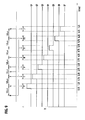
- the gate processing unit 461 is composed of delay circuits 50 different from one another in delay time, SR flip-flop circuits 51, an OR circuit 52, and an AND circuit 53.
- the gate processing unit 461 generates a gate of which switching time is 0.5 ⁇ s at every 1.0 ⁇ s.
- the pulse width thereof is 0.5 ⁇ s
- the repetition interval of the pulse is 1.0 ⁇ s. Accordingly, an incorrect signal denoted by reference symbol G in this diagram can be prevented from passing through the gate. Hence, it is made possible to accurately perform the phase locked processing and decoding processing, which follow the gate processing.
- the switching time of the gate is 0.5 ⁇ s has been shown in this embodiment, it is satisfactory, without being limited to this, if the gate generation interval is 1.0 ⁇ s according to the standard of the Mode S signal and that the switching time of the gate is sufficiently long for passing the signal therethrough.
- the synchronization execution unit 462 performs the phase locked processing after the above-described gate is generated.
- the pulse decoding unit 47 decodes the Mode S reply signal based on the pulse which has been subjected to the above-described gate processing and phase locked processing.
- the Mode S transponder transmission signal decoder 4a in this embodiment prevents the incorrect signal from passing through the gate when the phase locked processing is performed. Hence, the Mode S transponder transmission signal decoder 4a can accurately decode the Mode S reply signal.
- FIG. 10 is a configuration diagram of a Mode S transponder transmission signal decoder (Mode S reply signal decoder) 4b according to a second embodiment of the present invention.
- the Mode S transponder transmission signal decoder 4b is one, in which a change is added to the above-described Mode S transponder transmission signal decoder 4a, and a pattern selection unit 48 and a pulse position synchronization unit 49 are provided instead of the pulse phase locked loop unit 46.
- a repetition pattern of the pulse of the Mode S signal is predetermined, and is any one of patterns shown in FIGS. 11A to 11D.
- the above-described pattern selection unit 48 selects a pattern of the pulse, which most closely resembles a pattern of the regenerated pulse row, from these patterns of the pulses.
- the pulse position synchronization unit 49 performs pulse position synchronization processing based on the selected pattern of the pulse.
- the pulse position synchronization unit 49 calculates a correction value of the error, and gives feedback thereof to the pattern selection unit 48, and the pattern selection unit 48 sequentially corrects the reference position based on such a synchronization position correction signal obtained by calculating the correction value.
- References in the case of performing the pulse selection are L, N, P, T, and V.
- the correction values in all the references are continuously calculated in such a manner that the correction value in the reference N is calculated by measuring a width of M and that the correction value of the reference P is calculated next by measuring a width of O.
- R cannot be the reference since the pulse is not present there, and the correction value in the reference T is calculated based on a width of a double of a section Q, that is, a width of the section Q and a section S.
- the pulse decoding unit 47 decodes the above-described Mode S reply signal based on the above-described pulse which has been subjected to the pulse position synchronization processing.
- the appropriate pattern of the pulse is selected in advance in the case of performing the pulse position synchronization processing, and accordingly, the incorrect signal can be prevented from interposing in the pulse row.
- the reference positions in the case of selecting the pattern of the pulse are sequentially corrected, and accordingly, the selection of the pulse pattern can be performed appropriately. Hence, it is made possible to accurately decode the Mode S reply signal.
- Mode S transponder transmission signal decoder 4a or 4b of the present invention is applied to the SSR system, and these Mode S transponder transmission signal decoders 4a and 4b decode the Mode S reply signal 8 in the Mode S transponder transmission signal; however, the present invention is not limited to this.
- Mode S transponder transmission signal decoders 4a and 4b of the present invention are also applicable to an automatic dependent surveillance broad assistance (ADS-B) system using the above-described Mode S squitter signal, and it is also possible for the Mode S transponder transmission signal decoders 4a and 4b to decode the Mode S squitter signal included in the above-described Mode S transponder transmission signal.
- ADS-B automatic dependent surveillance broad assistance
- FIG. 13 is a configuration view of an ADS-B system 9 according to a third embodiment of the present invention.
- the ADS-B system 9 is composed of the transponders 6, antennas 61, receiver apparatuses 62, and the Mode S transponder transmission signal decoders 4a or 4b, which are mounted on the aircrafts 5 (two aircrafts 5a and 5b in this drawing), a ground-based omni antenna 10, a receiver apparatus 11, and the Mode S transponder transmission signal decoder 4a or 4b.
- the Mode S transponder transmission signal decoders 4a or 4b are provided not only on the ground but also in the aircrafts 5a and 5b.
- Mode S transponder transmission signal decoders 4a or 4b of the above-described aircrafts 5a and 5b can be disposed at arbitrary positions in the aircrafts.
- Each of the transponders 6 automatically transmits a Mode S squitter signal (including the Mode S short squitter signal and the Mode S extended squitter signal) 12 at a predetermined interval.
- the transmitted squitter signal 12 is received by the receiver apparatus 62 of the other aircraft 5a or 5b and the receiver apparatus 11 on the ground.
- the omni antenna 10 can perform the surveillance without being affected by a terrain and a state of the subject to be surveyed since it is possible to easily dispose the omni antenna 10 also in the mountainous area.
- Mode S short squitter signal can be used for initial acquisition of the aircraft, and the like, and accordingly, the ADS-B system 9 of this embodiment can be made to function as an airborne collision avoidance system (ACAS).
- ACAS airborne collision avoidance system
- the Mode S extended squitter signal is one in which an amount of data transmission is increased by extending a signal length of the above-described Mode S short squitter signal, and can transmit a variety of information such as a position, speed, flight-number, and existence of an intention of diversion of the aircraft itself.
- the ADS-B system 9 of this embodiment can be made to function as an airborne separation assurance system (ASAS).
- ASAS airborne separation assurance system
- Mode S transponder transmission signal decoders 4a and 4b in this embodiment are similar to those of the above-described first and second embodiments. Hence, the Mode S transponder transmission signal decoders 4a and 4b can accurately decode the Mode S squitter signal.
- each of the radar antenna apparatus 2 and the transceiver apparatus 3 (FIG. 4) and of the omni antenna 10 and the receiver apparatus 11 (FIG. 13) is one.
- three or more of each are arranged separately from one another, thus making it possible to impart a multilateration function to each of the above-described SSR system 1 and ADS-B system 9.
- the reply signal, the squitter signal, and the like, which are transmitted from the aircraft are received by three or more receiving stations.
- differences in receiving time among the receiving stations are converted into differences in distance between the respective receiving stations and the aircraft, an intersection point of hyperbolas formed under a condition where such a distance difference is constant is obtained, and the position of the aircraft is thus calculated.
- This multilateration can prevent lowering of surveillance performance owing to the bad weather and the like, and misidentification of the subject to be surveyed owing to a multipath error. Therefore, the multilateration is suitable for surveillance and the like for a region which is not covered with the radar surveillance on an airport surface.
- Mode S transponder transmission signal decoding method using the Mode S transponder transmission signal decoder as described above is also incorporated in the scope of the present invention.
Abstract
Description
- This application is based upon and claims the benefit of priority from the prior Japanese Application No. 2004-351163, filed on December 3, 20004; the entire contents of which are incorporated herein by reference.
- The present invention relates to a Mode S transponder transmission signal decoder and a Mode S transponder transmission signal decoding method for decoding a Mode S reply signal to a Mode S interrogation signal transmitted to a transponder mounted on an aircraft, and a decoding Mode S squitter signal (including a Mode S short squitter signal and a Mode S extended squitter signal) transmitted by the transponder.
- An aircraft surveillance radar for use in air traffic control is broadly divided into a primary surveillance radar (PSR) and a secondary surveillance radar (SSR).
- The above-described PSR emits radio waves from the ground, and receives and processes reflected waves thereof, thereby acquiring positional information of an aircraft.
- Meanwhile, the SSR transmits an interrogation signal from the ground, receives a reply signal thereto from a transponder, thereby acquiring a variety of information regarding the aircraft.
- Note that modes of the SSR are classified into a Mode A, a Mode C, and a Mode S depending on types of the information to be acquired, in which the Mode A is one for acquiring identification information of the aircraft, the Mode C is one for acquiring altitude information, and the Mode S is one for acquiring track information, speed information, and the like in addition to the above-described information (refer to HASHIDA Yoshio, OOTOMO Hisashi, and KUJI Yoshinori, "Secondary Surveillance Radar for Air Traffic Control ― SSR Mode S", Toshiba Review, Vol. 59, No. 2 (2004), pp. 58-61).
- Moreover, a transponder for the Mode S has a function to transmit a Mode S short squitter signal, which has a signal format similar to that of a Mode S reply signal and is composed of a 24-bit address, and to transmit a Mode S extended squitter signal, which has also the signal format similar to that of the Mode S reply signal and represents a position, a speed, and the like of the aircraft itself. Note that, in the following description, the above-described Mode S short squitter signal and Mode S extended squitter signal are collectively referred to as a "Mode S squitter signal" as appropriate.
- The above-described Mode S squitter signal is automatically transmitted from the Mode S transponder at a fixed interval, and is receivable not only at a ground station but also at the aircraft. Therefore, the Mode S squitter signal can be used for automatic dependent surveillance broad assistance (ADS-B).
- In the case of decoding the above-described SSR Mode S reply signal and Mode S squitter signal, a threshold value has been set as shown in FIG. 1A, and portions, where outputs are larger than the threshold value, and pulse widths are within a predetermined range as shown in FIG. 1B, have been recognized as such signals.
- Note that FIG. 1B shows the case where a width of a pulse W is within the predetermined range, a width of a pulse X does not meet a lower limit value of the predetermined range, and a width of a pulse Y exceeds an upper limit value of the predetermined range. Specifically, only the pulse W is recognized as a correct signal.
- However, as shown in FIG. 2A, a
direct wave 104 of the Mode S reply signal transmitted from anaircraft 101 to aground station 102 in response to a ModeS interrogation signal 103 from theground station 102 is sometimes subjected to interference from areflected wave 105 of the same Mode S reply signal. Moreover, this phenomenon sometimes occurs also in the case of receiving the Mode S squitter signal. - Note that, in the following description, the above-described Mode S reply signal and Mode S squitter signal are collectively referred to as a "Mode S transponder transmission signal" as appropriate.
- The interference as described above by the reflective wave is caused by a phase difference between access routes, and a power level P of the Mode S transponder transmission signal received by the
ground station 102 is represented by the following expression.
- Note that, in the above-described Expression (1), P is the receiving power level, α is an attenuation of the direct wave, B is an attenuation of the reflected wave, and d is a time difference of arrival.
- Moreover, when there is a plurality of aircrafts within a surveillance range of the
ground station 102 as shown in FIG. 2B, the Mode Stransponder transmission signal 104 from theaircraft 101 and a Mode S transponder transmission signal (asynchronous signal) 107 from anaircraft 106 sometimes interfere with each other. - Specifically, if it is assumed that a pulse shown in FIG. 3A is the
direct wave 104, and that a pulse shown in FIG. 3B is thereflected wave 105 or theasynchronous signal 107, an associated wave as shown in FIG. 3C is formed when phases of these two pulses are the same. A pulse of the associated wave is misidentified so as to exceed the upper limit value of the above-described predetermined range, and as a result, the pulse concerned is not recognized as the correct signal. Hence, it becomes impossible to correctly decode the Mode S transponder transmission signal. - Meanwhile, when the phases of the two pulses are different from each other, an associated wave as shown in FIG. 3D is formed. A pulse of the associated wave is misidentified so as not to meet the lower limit value of the above-described predetermined range, and as a result, the pulse concerned is not recognized as the correct signal. Hence, it becomes impossible to correctly decode the Mode S transponder transmission signal as in the case shown in FIG. 3C.
- In consideration of the circumstances as described above, it is an object of the present invention to provide a Mode S transponder transmission signal decoder and a Mode S transponder transmission signal decoding method, which are capable of correctly decoding the Mode S transponder transmission signal.
- A first aspect of the present invention provides a Mode S transponder transmission signal decoder for decoding a Mode S transponder transmission signal transmitted by a transponder mounted on an aircraft, including: a differential processing unit which performs differential processing for the Mode S transponder transmission signal; an auto correlation arithmetic operation unit which performs an arithmetic operation of a degree of auto auto correlation between an increasing change rate and decreasing change rate of a power level in the signal which has been subjected to the differential processing; a pulse regeneration unit which specifies a position of a pulse in the signal which has been subjected to the auto correlation arithmetic operation processing and regenerating the pulse based on the degree of auto correlation and a standard of a Mode S signal, the degree having been obtained by the auto correlation arithmetic operation processing; a phase locked loop unit which performs gate processing and phase locked processing for the regenerated pulse based on the standard of the Mode S signal; and a decoding unit which decodes the Mode S transponder transmission signal based on the pulse which has been subjected to the gate processing and the phase locked processing.
- A second aspect of the present invention provides a Mode S transponder transmission signal decoder for decoding a Mode S transponder transmission signal transmitted by a transponder mounted on an aircraft, including: a differential processing unit which performs differential processing for the Mode S transponder transmission signal; an auto correlation arithmetic operation unit which performs an arithmetic operation of a degree of auto correlation between an increasing change rate and decreasing change rate of a power level in the signal which has been subjected to the differential processing; a pulse regeneration unit which specifies a position of a pulse in the signal which has been subjected to the auto correlation arithmetic operation processing and regenerating the pulse based on the degree of auto correlation and a standard of a Mode S signal, the degree having been obtained by the auto correlation arithmetic operation processing; a pattern selection unit which selects a pattern of the pulse, the pattern most closely resembling a pattern of the regenerated pulse, from patterns of pulses defined by the standard of the Mode S signal; a position synchronization unit which performs pulse position synchronization processing based on the selected pattern of the pulse; and a decoding unit which decodes the Mode S transponder transmission signal based on the pulse which has been subjected to the pulse position synchronization processing, wherein the position synchronization unit includes a correction value calculation unit which calculates a correction value of an error when the error occurs in a reference position in the case of selecting the resembling pattern of the pulse, and the pattern selection unit sequentially corrects the reference position based on the correction value.
- A third aspect of the present invention provides a Mode S transponder transmission signal decoding method for decoding a Mode S transponder transmission signal transmitted by a transponder mounted on an aircraft, comprising: performing differential processing for the Mode S transponder transmission signal; performing an arithmetic operation of a degree of auto correlation between an increasing change rate and decreasing change rate of a power level in the signal which has been subjected to the differential processing; specifying a position of a pulse in the signal which has been subjected to the auto correlation arithmetic operation processing and regenerating the pulse based on the degree of auto correlation and a standard of a Mode S signal, the degree having been obtained by the auto correlation arithmetic operation processing; performing gate processing and phase locked processing for the regenerated pulse based on the standard of the Mode S signal; and decoding the Mode S transponder transmission signal based on the pulse which has been subjected to the gate processing and the phase locked processing.
- A fourth aspect of the present invention provides a Mode S transponder transmission signal decoding method for decoding a Mode S transponder transmission signal transmitted by a transponder mounted on an aircraft, comprising: performing differential processing for the Mode S transponder transmission signal; performing an arithmetic operation of a degree of auto correlation between an increasing change rate and decreasing change rate of a power level in the signal which has been subjected to the differential processing; specifying a position of a pulse in the signal which has been subjected to the auto correlation arithmetic operation processing and regenerating the pulse based on the degree of auto correlation and a standard of a Mode S signal, the degree having been obtained by the auto correlation arithmetic operation processing; selecting a pattern of the pulse, the pattern most closely resembling a pattern of the regenerated pulse, from patterns of pulses defined by the standard of the Mode S signal; performing pulse position synchronization processing based on the selected pattern of the pulse; and decoding the Mode S transponder transmission signal based on the pulse which has been subjected to the pulse position synchronization processing, wherein the pulse position synchronization processing step includes calculating a correction value of an error when the error occurs in a reference position in a case of selecting the resembling pattern of the pulse, and in the pulse pattern selection step, the reference position is sequentially corrected based on the correction value.
- In the above-described aspects of the present invention; in the case of decoding the Mode S transponder transmission signal, the differential processing, the auto correlation arithmetic operation processing, the pulse regeneration processing, the gate processing, and the phase locked processing are performed.
- Alternatively, the differential processing, the auto correlation arithmetic operation processing, the pulse regeneration processing, the pattern selection processing, the position synchronization processing, and the correction value calculation processing are performed.
- Hence, it is made possible to accurately decode the Mode S transponder transmission signal.
-
- FIGS. 1A and 1B are diagrams for explaining a decoding method of a conventional reply signal.
- FIGS. 2A and 2B are views for explaining reflection and interference of the conventional reply signal.
- FIGS. 3A to 3D are diagrams for explaining a pulse change of the conventional reply signal.
- FIG. 4 is a view showing a configuration of a secondary surveillance radar system according to a first embodiment of the present invention.
- FIG. 5 is a diagram showing a configuration of a Mode S reply signal decoder according to the first embodiment of the present invention.
- FIGS. 6A and 6B are diagrams for explaining differential processing in the Mode S reply signal decoder according to the first embodiment of the present invention.
- FIG. 7 is a diagram for explaining an auto correlation arithmetic operation in the Mode S reply signal decoder according to the first embodiment of the present invention.
- FIG. 8 is a diagram showing details of a gate processing unit of FIG. 5.
- FIG. 9 is a diagram for explaining gate processing in the gate processing unit of FIG. 5.
- FIG. 10 is a diagram showing a configuration of a Mode S reply signal decoder according to a second embodiment of the present invention.
- FIGS. 11A to 11D are diagrams showing patterns of a pulse of a Mode S reply signal in the Mode S reply signal decoder according to the second embodiment of the present invention.
- FIG. 12 is a diagram for explaining pulse position synchronization processing in the Mode S reply signal decoder according to the second embodiment of the present invention.
- FIG. 13 is a view showing a configuration of an automatic dependent surveillance broad assistance system according to a third embodiment of the present invention.
- A description is made below of embodiments of a Mode S transponder transmission signal decoder and Mode S transponder transmission signal decoding method of the present invention while submitting the drawings.
- Note that the following embodiments are strictly for the purpose of explaining the present invention, and do not limit the scope of the present invention. Hence, it is possible for those skilled in the art to adopt various embodiments incorporating each or the entire elements of the embodiments to be described below, and such various embodiments are also incorporated in the scope of the present invention.
- Moreover, in all the drawings for explaining the following embodiments, the same reference numerals are assigned to the same elements, and duplicate descriptions of the elements concerned are omitted.
- FIG. 4 is a configuration view of a secondary surveillance radar (SSR)
system 1 according to a first embodiment of the present invention. - The
SSR system 1 is composed of aradar antenna apparatus 2 including a ground-based radar antenna rotatable at 360° in the horizontal direction, atransceiver apparatus 3, a Mode S transpondertransmission signal decoder 4a, and a transponder (Mode S transponder) 6 mounted on anaircraft 5. - The
transceiver apparatus 3 transmits a ModeS interrogation signal 7 to the transponder 6 through theradar antenna apparatus 2, and the transponder 6 which has received the ModeS interrogation signal 7 transmits a ModeS reply signal 8 to the received Mode S interrogation signal. The ModeS reply signal 8 is received by theradar antenna apparatus 2 and thetransceiver apparatus 3, and is decoded by the Mode S transpondertransmission signal decoder 4a. Specifically, the Mode S transpondertransmission signal decoder 4a functions as a Mode S reply signal decoder. - Note that, in this drawing, descriptions of a generation unit of the Mode S interrogation signal, an interface unit for submitting a variety of information to a user, and the like are omitted.
- FIG. 5 is a configuration diagram of the Mode S transponder
transmission signal decoder 4a according to the first embodiment of the present invention, which is shown in FIG. 4. - The Mode S transponder
transmission signal decoder 4a is composed of adetection unit 41, an A/D conversion unit 42, adifferential processing unit 43, an auto correlationarithmetic operation unit 44, apulse regeneration unit 45, a pulse phase lockedloop unit 46, and apulse decoding unit 47. - The
detection unit 41 performs detection processing for a received RF signal, and the A/D conversion unit 42 converts the detected signal into a multilevel digital signal. - The
differential processing unit 43 performs differential processing for the digital signal having a waveform as shown in FIG. 6A. The waveform of the signal which has been subjected to the differential processing becomes as shown in FIG. 6B. - The auto correlation
arithmetic operation unit 44 performs auto correlation arithmetic operation processing for the differentiated signal. In this processing, a degree (power level) of auto correlation between an increasing change rate and decreasing change rate of a power level in the differentiated signal is arithmetically operated. - With regard to the Mode S reply signal, a pulse width thereof is defined at 1.0 µs or 0.5 µs by a standard thereof, and accordingly, strong auto correlations appear at P(t) · (-P(t+0.5)) and P(t) · (-P(t+1.0)) (A, B and C in FIG. 7).
- The
pulse regeneration unit 45 specifies positions of pulses and regenerates a pulse row based on the degree of auto correlation and the standard of the Mode S reply signal, which are described above. Note that, in this case, a threshold value of the degree of auto correlation is used, and the pulses are regenerated on portions having the degree of auto correlation, which is equal to or more than the threshold value. - The pulse phase locked
loop unit 46 performs gate processing and phase locked processing for the regenerated pulse row based on the standard of the Mode S signal. - The pulse phase locked
loop unit 46 is composed of agate processing unit 461 and asynchronization execution unit 462. - As shown in FIG. 8, the
gate processing unit 461 is composed of delay circuits 50 different from one another in delay time, SR flip-flop circuits 51, an ORcircuit 52, and an ANDcircuit 53. - As shown in FIG. 9, the
gate processing unit 461 generates a gate of which switching time is 0.5 µs at every 1.0 µs. In the standard of the Mode S signal, the pulse width thereof is 0.5 µs, and the repetition interval of the pulse is 1.0 µs. Accordingly, an incorrect signal denoted by reference symbol G in this diagram can be prevented from passing through the gate. Hence, it is made possible to accurately perform the phase locked processing and decoding processing, which follow the gate processing. - Note that, though the case where the switching time of the gate is 0.5 µs has been shown in this embodiment, it is satisfactory, without being limited to this, if the gate generation interval is 1.0 µs according to the standard of the Mode S signal and that the switching time of the gate is sufficiently long for passing the signal therethrough.
- The
synchronization execution unit 462 performs the phase locked processing after the above-described gate is generated. - The
pulse decoding unit 47 decodes the Mode S reply signal based on the pulse which has been subjected to the above-described gate processing and phase locked processing. - As described above, the Mode S transponder
transmission signal decoder 4a in this embodiment prevents the incorrect signal from passing through the gate when the phase locked processing is performed. Hence, the Mode S transpondertransmission signal decoder 4a can accurately decode the Mode S reply signal. - FIG. 10 is a configuration diagram of a Mode S transponder transmission signal decoder (Mode S reply signal decoder) 4b according to a second embodiment of the present invention.
- The Mode S transponder
transmission signal decoder 4b is one, in which a change is added to the above-described Mode S transpondertransmission signal decoder 4a, and apattern selection unit 48 and a pulseposition synchronization unit 49 are provided instead of the pulse phase lockedloop unit 46. - A repetition pattern of the pulse of the Mode S signal is predetermined, and is any one of patterns shown in FIGS. 11A to 11D.
- The above-described
pattern selection unit 48 selects a pattern of the pulse, which most closely resembles a pattern of the regenerated pulse row, from these patterns of the pulses. - The pulse
position synchronization unit 49 performs pulse position synchronization processing based on the selected pattern of the pulse. - Note that, in the case of performing the above-described pulse selection, there is a possibility that an error occurs in a reference position of the pulse. Accordingly, the pulse
position synchronization unit 49 calculates a correction value of the error, and gives feedback thereof to thepattern selection unit 48, and thepattern selection unit 48 sequentially corrects the reference position based on such a synchronization position correction signal obtained by calculating the correction value. - Details of the above-described processing are described below while referring to FIG. 12.
- References in the case of performing the pulse selection are L, N, P, T, and V. The correction values in all the references are continuously calculated in such a manner that the correction value in the reference N is calculated by measuring a width of M and that the correction value of the reference P is calculated next by measuring a width of O.
- Note that R cannot be the reference since the pulse is not present there, and the correction value in the reference T is calculated based on a width of a double of a section Q, that is, a width of the section Q and a section S.
- The
pulse decoding unit 47 decodes the above-described Mode S reply signal based on the above-described pulse which has been subjected to the pulse position synchronization processing. - As described above, in the Mode S transponder
transmission signal decoder 4b of this embodiment, the appropriate pattern of the pulse is selected in advance in the case of performing the pulse position synchronization processing, and accordingly, the incorrect signal can be prevented from interposing in the pulse row. Moreover, the reference positions in the case of selecting the pattern of the pulse are sequentially corrected, and accordingly, the selection of the pulse pattern can be performed appropriately. Hence, it is made possible to accurately decode the Mode S reply signal. - In the above-described embodiments, the case has been described, where the Mode S transponder
transmission signal decoder transmission signal decoders S reply signal 8 in the Mode S transponder transmission signal; however, the present invention is not limited to this. - Specifically, the Mode S transponder
transmission signal decoders transmission signal decoders - FIG. 13 is a configuration view of an ADS-
B system 9 according to a third embodiment of the present invention. - The ADS-
B system 9 is composed of the transponders 6,antennas 61,receiver apparatuses 62, and the Mode S transpondertransmission signal decoders aircrafts omni antenna 10, areceiver apparatus 11, and the Mode S transpondertransmission signal decoder - Specifically, in the ADS-
B system 9 of this embodiment, the Mode S transpondertransmission signal decoders aircrafts - Note that the Mode S transponder
transmission signal decoders aircrafts - Each of the transponders 6 automatically transmits a Mode S squitter signal (including the Mode S short squitter signal and the Mode S extended squitter signal) 12 at a predetermined interval.
- The transmitted
squitter signal 12 is received by thereceiver apparatus 62 of theother aircraft receiver apparatus 11 on the ground. - Specifically, in the ADS-
B system 9, not only the surveillance of the aircrafts from the ground but also the mutual surveillance between theaircrafts 5 is possible. - Moreover, though it has been difficult for the conventional surveillance radar to survey a small aircraft flying in a mountainous area and at a low altitude, it is possible for the
omni antenna 10 to perform the surveillance without being affected by a terrain and a state of the subject to be surveyed since it is possible to easily dispose theomni antenna 10 also in the mountainous area. - Moreover, the above-described Mode S short squitter signal can be used for initial acquisition of the aircraft, and the like, and accordingly, the ADS-
B system 9 of this embodiment can be made to function as an airborne collision avoidance system (ACAS). - Meanwhile, the Mode S extended squitter signal is one in which an amount of data transmission is increased by extending a signal length of the above-described Mode S short squitter signal, and can transmit a variety of information such as a position, speed, flight-number, and existence of an intention of diversion of the aircraft itself. Hence, the ADS-
B system 9 of this embodiment can be made to function as an airborne separation assurance system (ASAS). - Furthermore, functions, configurations, and the like of the Mode S transponder
transmission signal decoders transmission signal decoders - In all the above-described embodiments, the case has been described, where each of the
radar antenna apparatus 2 and the transceiver apparatus 3 (FIG. 4) and of theomni antenna 10 and the receiver apparatus 11 (FIG. 13) is one. However, three or more of each are arranged separately from one another, thus making it possible to impart a multilateration function to each of the above-describedSSR system 1 and ADS-B system 9. - In multilateration, the reply signal, the squitter signal, and the like, which are transmitted from the aircraft, are received by three or more receiving stations. Next, differences in receiving time among the receiving stations are converted into differences in distance between the respective receiving stations and the aircraft, an intersection point of hyperbolas formed under a condition where such a distance difference is constant is obtained, and the position of the aircraft is thus calculated.
- This multilateration can prevent lowering of surveillance performance owing to the bad weather and the like, and misidentification of the subject to be surveyed owing to a multipath error. Therefore, the multilateration is suitable for surveillance and the like for a region which is not covered with the radar surveillance on an airport surface.
- Note that the Mode S transponder transmission signal decoding method using the Mode S transponder transmission signal decoder as described above is also incorporated in the scope of the present invention.
Claims (4)
- A Mode S transponder transmission signal decoder for decoding a Mode S transponder transmission signal transmitted by a transponder mounted on an aircraft, comprising:a differential processing unit which performs differential processing for the Mode S transponder transmission signal;an auto correlation arithmetic operation unit which performs an arithmetic operation of a degree of auto correlation between an increasing change rate and decreasing change rate of a power level in the signal which has been subjected to the differential processing;a pulse regeneration unit which specifies a position of a pulse in the signal which has been subjected to the auto correlation arithmetic operation processing and regenerates the pulse based on the degree of auto correlation and a standard of a Mode S signal, the degree having been obtained by the auto correlation arithmetic operation processing;a phase locked loop unit which performs gate processing and phase locked processing for the regenerated pulse based on the standard of the Mode S signal; anda decoding unit which decodes the Mode S transponder transmission signal based on the pulse which has been subjected to the gate processing and the phase locked processing.
- A Mode S transponder transmission signal decoder for decoding a Mode S transponder transmission signal transmitted by a transponder mounted on an aircraft, comprising:a differential processing unit which performs differential processing for the Mode S transponder transmission signal;an auto correlation arithmetic operation unit which performs an arithmetic operation of a degree of auto correlation between an increasing change rate and decreasing change rate of a power level in the signal which has been subjected to the differential processing;a pulse regeneration unit which specifies a position of a pulse in the signal which has been subjected to the auto correlation arithmetic operation processing and regenerates the pulse based on the degree of auto correlation and a standard of a Mode S signal, the degree having been obtained by the auto correlation arithmetic operation processing;a pattern selection unit which selects a pattern of the pulse, the pattern most closely resembling a pattern of the regenerated pulse, from patterns of pulses defined by the standard of the Mode S signal;a position synchronization unit which performs pulse position synchronization processing based on the selected pattern of the pulse; anda decoding unit which decodes the Mode S transponder transmission signal based on the pulse which has been subjected to the pulse position synchronization processing,wherein the position synchronization unit includes a correction value calculation unit which calculates a correction value of an error when the error occurs in a reference position in a case of selecting the resembling pattern of the pulse, andthe pattern selection unit sequentially corrects the reference position based on the correction value.
- A Mode S transponder transmission signal decoding method for decoding a Mode S transponder transmission signal transmitted by a transponder mounted on an aircraft, comprising:performing differential processing for the Mode S transponder transmission signal;performing an arithmetic operation of a degree of auto correlation between an increasing change rate and decreasing change rate of a power level in the signal which has been subjected to the differential processing;specifying a position of a pulse in the signal which has been subjected to the auto correlation arithmetic operation processing and regenerating the pulse based on the degree of auto correlation and a standard of a Mode S signal, the degree having been obtained by the auto correlation arithmetic operation processing;performing gate processing and phase locked processing for the regenerated pulse based on the standard of the Mode S signal; anddecoding the Mode S transponder transmission signal based on the pulse which has been subjected to the gate processing and the phase locked processing.
- A Mode S transponder transmission signal decoding method for decoding a Mode S transponder transmission signal transmitted by a transponder mounted on an aircraft, comprising:performing differential processing for the Mode S transponder transmission signal;performing an arithmetic operation of a degree of auto correlation between an increasing change rate and decreasing change rate of a power level in the signal which has been subjected to the differential processing;specifying a position of a pulse in the signal which has been subjected to the auto correlation arithmetic operation processing and regenerating the pulse based on the degree of auto correlation and a standard of a Mode S signal, the degree having been obtained by the auto correlation arithmetic operation processing;selecting a pattern of the pulse, the pattern most closely resembling a pattern of the regenerated pulse, from patterns of pulses defined by the standard of the Mode S signal;performing pulse position synchronization processing based on the selected pattern of the pulse; anddecoding the Mode S transponder transmission signal based on the pulse which has been subjected to the pulse position synchronization processing,wherein the pulse position synchronization processing step includes calculating a correction value of an error when the error occurs in a reference position in a case of selecting the resembling pattern of the pulse, andin the pulse pattern selection step, the reference position is sequentially corrected based on the correction value.
Applications Claiming Priority (1)
| Application Number | Priority Date | Filing Date | Title |
|---|---|---|---|
| JP2004351163A JP4331094B2 (en) | 2004-12-03 | 2004-12-03 | Mode S transponder transmission signal decoding apparatus and mode S transponder transmission signal decoding method |
Publications (3)
| Publication Number | Publication Date |
|---|---|
| EP1666917A2 true EP1666917A2 (en) | 2006-06-07 |
| EP1666917A3 EP1666917A3 (en) | 2010-03-17 |
| EP1666917B1 EP1666917B1 (en) | 2012-02-22 |
Family
ID=35985327
Family Applications (1)
| Application Number | Title | Priority Date | Filing Date |
|---|---|---|---|
| EP05257140A Expired - Fee Related EP1666917B1 (en) | 2004-12-03 | 2005-11-21 | Decoder and decoding method for Mode S transponder transmission signal |
Country Status (3)
| Country | Link |
|---|---|
| US (2) | US7391359B2 (en) |
| EP (1) | EP1666917B1 (en) |
| JP (1) | JP4331094B2 (en) |
Cited By (3)
| Publication number | Priority date | Publication date | Assignee | Title |
|---|---|---|---|---|
| US7965227B2 (en) | 2006-05-08 | 2011-06-21 | Era Systems, Inc. | Aircraft tracking using low cost tagging as a discriminator |
| CN104330774A (en) * | 2014-11-15 | 2015-02-04 | 安徽四创电子股份有限公司 | FPGA (Field Programmable Gate Array)-based S-mode secondary radar decoder and testing and error correction method thereof |
| CN109131909A (en) * | 2018-08-17 | 2019-01-04 | 中国航空无线电电子研究所 | anti-collision system based on ADS-B |
Families Citing this family (39)
| Publication number | Priority date | Publication date | Assignee | Title |
|---|---|---|---|---|
| US7908077B2 (en) | 2003-06-10 | 2011-03-15 | Itt Manufacturing Enterprises, Inc. | Land use compatibility planning software |
| US7667647B2 (en) | 1999-03-05 | 2010-02-23 | Era Systems Corporation | Extension of aircraft tracking and positive identification from movement areas into non-movement areas |
| US7777675B2 (en) | 1999-03-05 | 2010-08-17 | Era Systems Corporation | Deployable passive broadband aircraft tracking |
| US7739167B2 (en) | 1999-03-05 | 2010-06-15 | Era Systems Corporation | Automated management of airport revenues |
| US7570214B2 (en) | 1999-03-05 | 2009-08-04 | Era Systems, Inc. | Method and apparatus for ADS-B validation, active and passive multilateration, and elliptical surviellance |
| US8446321B2 (en) | 1999-03-05 | 2013-05-21 | Omnipol A.S. | Deployable intelligence and tracking system for homeland security and search and rescue |
| US7889133B2 (en) | 1999-03-05 | 2011-02-15 | Itt Manufacturing Enterprises, Inc. | Multilateration enhancements for noise and operations management |
| US8203486B1 (en) | 1999-03-05 | 2012-06-19 | Omnipol A.S. | Transmitter independent techniques to extend the performance of passive coherent location |
| US7782256B2 (en) | 1999-03-05 | 2010-08-24 | Era Systems Corporation | Enhanced passive coherent location techniques to track and identify UAVs, UCAVs, MAVs, and other objects |
| FR2860882B1 (en) * | 2003-10-10 | 2006-02-03 | Thales Sa | METHOD FOR PRE-DETECTING RESPONSES IN SECONDARY RADAR AND APPLICATION TO DETECTION OF S MODE RESPONSES |
| JP4331094B2 (en) * | 2004-12-03 | 2009-09-16 | 株式会社東芝 | Mode S transponder transmission signal decoding apparatus and mode S transponder transmission signal decoding method |
| JP4498332B2 (en) * | 2006-09-14 | 2010-07-07 | 株式会社東芝 | Mode S secondary monitoring radar device |
| JP4724097B2 (en) * | 2006-11-24 | 2011-07-13 | 株式会社東芝 | ADS-B inspection device |
| JP4679500B2 (en) * | 2006-12-12 | 2011-04-27 | 株式会社東芝 | ADS-B ground station |
| FR2909772B1 (en) * | 2006-12-12 | 2012-12-21 | Thales Sa | METHOD OF REDUCING MULPOSRATE PROPAGATION EFFECTS WHEN PROCESSING "S" MODE RESPONSES |
| US7414567B2 (en) * | 2006-12-22 | 2008-08-19 | Intelligent Automation, Inc. | ADS-B radar system |
| JP4966031B2 (en) * | 2007-01-22 | 2012-07-04 | 株式会社東芝 | Mode S secondary monitoring radar |
| ITTO20070623A1 (en) * | 2007-09-03 | 2009-03-04 | Selex Sistemi Integrati Spa | DETECTION OF REPLICATIONS IN A SECONDARY SURVEILLANCE RADAR |
| JP5072868B2 (en) * | 2009-01-06 | 2012-11-14 | 株式会社東芝 | Air traffic control radar and squitter identification method |
| JP5398343B2 (en) * | 2009-05-15 | 2014-01-29 | 株式会社東芝 | Secondary surveillance radar |
| FR2946482B1 (en) * | 2009-06-03 | 2012-03-30 | Thales Sa | METHOD FOR DETECTING A MESSAGE ISSUED BY A S MODE INTERROGATOR OR ANSWERING MACHINE |
| US8102301B2 (en) * | 2009-12-18 | 2012-01-24 | Garmin International, Inc. | Self-configuring ADS-B system |
| EP2548041B1 (en) * | 2010-03-17 | 2016-07-27 | Honeywell International Inc. | Systems and methods for short baseline, low cost determination of airborne aircraft location |
| JP5622496B2 (en) * | 2010-09-14 | 2014-11-12 | 株式会社東芝 | Receiver and multilateration system |
| JP2012122775A (en) * | 2010-12-06 | 2012-06-28 | Nec Corp | Aircraft position measuring system, time synchronization method, and time synchronization program for use in the system |
| JP5713723B2 (en) * | 2011-02-21 | 2015-05-07 | 三菱電機株式会社 | Receiver |
| JP2012237710A (en) * | 2011-05-13 | 2012-12-06 | Toshiba Corp | Wide area multilateration system and receiver |
| US9285472B2 (en) * | 2011-12-06 | 2016-03-15 | L-3 Communications Avionics Systems, Inc. | Multi-link transponder for aircraft and method of providing multi-link transponder capability to an aircraft having an existing transponder |
| SG11201708119WA (en) * | 2015-04-03 | 2017-11-29 | Dali Systems Co Ltd | Method and system for link synchronization in an lte-tdd architecture |
| US10733894B1 (en) | 2015-08-24 | 2020-08-04 | uAvionix Corporation | Direct-broadcast remote identification (RID) device for unmanned aircraft systems (UAS) |
| US9906265B1 (en) | 2015-10-08 | 2018-02-27 | uAvionix Corporation | Manchester correlator |
| US10991260B2 (en) | 2015-08-24 | 2021-04-27 | uAvionix Corporation | Intelligent non-disruptive automatic dependent surveillance-broadcast (ADS-B) integration for unmanned aircraft systems (UAS) |
| US11222547B2 (en) | 2015-08-24 | 2022-01-11 | Uavionics Corporation | Intelligent non-disruptive automatic dependent surveillance-broadcast (ADS-B) integration for unmanned aircraft systems (UAS) |
| JP6790464B2 (en) * | 2016-05-30 | 2020-11-25 | 日本電気株式会社 | Position matching device, ADS-B report acquisition device and position matching method |
| JP6790465B2 (en) * | 2016-05-30 | 2020-11-25 | 日本電気株式会社 | ADS-B report acquisition device and method |
| US10043405B1 (en) * | 2017-03-14 | 2018-08-07 | Architecture Technology Corporation | Advisor system and method |
| CN110646766B (en) * | 2019-09-23 | 2022-02-18 | 四川九洲电器集团有限责任公司 | S-mode interrogation signal detection method, storage medium and detection device |
| AU2020409427A1 (en) * | 2019-12-20 | 2022-03-10 | Denann Consultant Services Pty. Ltd. | Airport advertising system |
| US11817935B2 (en) | 2020-07-10 | 2023-11-14 | Skystream LLC | Automatic dependent surveillance-broadcast (ADS-B) device having coarse and fine accuracy flight position data and associated methods |
Citations (1)
| Publication number | Priority date | Publication date | Assignee | Title |
|---|---|---|---|---|
| WO2003098824A2 (en) * | 2002-05-22 | 2003-11-27 | Commissariat A L'energie Atomique | Demodulator for pulse-position modulated signals, demodulation method and signal receiver equipped with same |
Family Cites Families (9)
| Publication number | Priority date | Publication date | Assignee | Title |
|---|---|---|---|---|
| FR2654217B1 (en) * | 1989-11-03 | 1992-01-17 | Thomson Csf | DEVICE FOR DETECTING RESPONDER SIGNALS QUERYED BY A SECONDARY RADAR IN THE PRESENCE OF MULTIPATH PHENOMENES. |
| US5089822A (en) * | 1990-02-13 | 1992-02-18 | Avion Systems, Inc. | Interrogation signal processor for air traffic control communications |
| FR2692995B1 (en) * | 1992-06-30 | 1994-08-26 | Thomson Csf | Pulse recognition method and device and use for filtering Mode S responses from a secondary radar. |
| US6222480B1 (en) * | 1999-03-24 | 2001-04-24 | Alliedsignal | Multifunction aircraft transponder |
| ITRM20010176A1 (en) * | 2001-04-03 | 2002-10-03 | Univ Roma | RECEIVING AND PROCESSING APPARATUS FOR "REPLICA" SIGNALS OF SECONDARY SURVEILLANCE RADAR WITH SUPER RESOLUTION CAPACITY. |
| US6628225B2 (en) * | 2001-11-30 | 2003-09-30 | Raytheon Company | Reduced split target reply processor for secondary surveillance radars and identification friend or foe systems |
| US6768445B1 (en) * | 2002-12-18 | 2004-07-27 | Garmin International, Inc. | Device and method for SPR detection in a mode-s transponder |
| US6788245B1 (en) * | 2002-12-18 | 2004-09-07 | Garmin International, Inc. | Device and method for SPR detection in a mode-S transponder |
| JP4331094B2 (en) * | 2004-12-03 | 2009-09-16 | 株式会社東芝 | Mode S transponder transmission signal decoding apparatus and mode S transponder transmission signal decoding method |
-
2004
- 2004-12-03 JP JP2004351163A patent/JP4331094B2/en not_active Expired - Fee Related
-
2005
- 2005-11-21 EP EP05257140A patent/EP1666917B1/en not_active Expired - Fee Related
- 2005-11-22 US US11/283,816 patent/US7391359B2/en active Active
-
2007
- 2007-12-19 US US11/960,464 patent/US7471235B2/en active Active
Patent Citations (1)
| Publication number | Priority date | Publication date | Assignee | Title |
|---|---|---|---|---|
| WO2003098824A2 (en) * | 2002-05-22 | 2003-11-27 | Commissariat A L'energie Atomique | Demodulator for pulse-position modulated signals, demodulation method and signal receiver equipped with same |
Cited By (5)
| Publication number | Priority date | Publication date | Assignee | Title |
|---|---|---|---|---|
| US7965227B2 (en) | 2006-05-08 | 2011-06-21 | Era Systems, Inc. | Aircraft tracking using low cost tagging as a discriminator |
| CN104330774A (en) * | 2014-11-15 | 2015-02-04 | 安徽四创电子股份有限公司 | FPGA (Field Programmable Gate Array)-based S-mode secondary radar decoder and testing and error correction method thereof |
| CN104330774B (en) * | 2014-11-15 | 2017-01-25 | 安徽四创电子股份有限公司 | FPGA (Field Programmable Gate Array)-based S-mode secondary radar decoder |
| CN109131909A (en) * | 2018-08-17 | 2019-01-04 | 中国航空无线电电子研究所 | anti-collision system based on ADS-B |
| CN109131909B (en) * | 2018-08-17 | 2021-09-24 | 中国航空无线电电子研究所 | Anti-collision system based on ADS-B |
Also Published As
| Publication number | Publication date |
|---|---|
| US7391359B2 (en) | 2008-06-24 |
| JP2006162324A (en) | 2006-06-22 |
| US20080106456A1 (en) | 2008-05-08 |
| US7471235B2 (en) | 2008-12-30 |
| EP1666917B1 (en) | 2012-02-22 |
| US20060119502A1 (en) | 2006-06-08 |
| JP4331094B2 (en) | 2009-09-16 |
| EP1666917A3 (en) | 2010-03-17 |
Similar Documents
| Publication | Publication Date | Title |
|---|---|---|
| EP1666917B1 (en) | Decoder and decoding method for Mode S transponder transmission signal | |
| EP0735382B1 (en) | Improved processing for mode-S signals suffering multipath distortion | |
| EP3336580B1 (en) | Method and ads-b base station for validating position information contained in a mode s extended squitter message (ads-b) from an aircraft | |
| US5596332A (en) | Aircraft location and identification system | |
| US6094169A (en) | Multilateration auto-calibration and position error correction | |
| US6222480B1 (en) | Multifunction aircraft transponder | |
| US6313783B1 (en) | Transponder having directional antennas | |
| US6433729B1 (en) | System and method for displaying vertical profile of intruding traffic in two dimensions | |
| US7501977B2 (en) | Mode S radar | |
| US5691723A (en) | Apparatus and method for encoding and decoding data on tactical air navigation and distance measuring equipment signals | |
| US5063386A (en) | Device for the detection of the signals of transponders interrogated by a secondary radar in the presence of multiple-path phenomena | |
| US20080150784A1 (en) | Ads-b radar system | |
| CN203070092U (en) | Simulation test system of airborne crashproof unit | |
| KR20220014319A (en) | Secondary radar improving aerial safety via very-long-range ads-b detection | |
| US5463398A (en) | Method and apparatus for multiple reply rejection when decoding transponder replay signals | |
| US9100087B2 (en) | Systems and methods for providing surface multipath mitigation | |
| AU600740B2 (en) | Advanced instrument landing system | |
| US4918610A (en) | Navigation, communication, and surveillance system based on DME | |
| CN109050583B (en) | Urban rail train anti-collision early warning method and system | |
| Redlien et al. | Microwave landing system: the new international standard | |
| US7847722B2 (en) | Secondary surveillance radar and method of analyzing replies for secondary surveillance radar | |
| Švábeník et al. | Separation of secondary surveillance radar signals | |
| JPS61256272A (en) | Airplane discrimination apparatus by ssr system | |
| Beason | A new multilateration optimization technique for air traffic management and surveillance | |
| Wang | Receiving and processing ADS-B signals for aircraft tracking |
Legal Events
| Date | Code | Title | Description |
|---|---|---|---|
| PUAI | Public reference made under article 153(3) epc to a published international application that has entered the european phase |
Free format text: ORIGINAL CODE: 0009012 |
|
| 17P | Request for examination filed |
Effective date: 20051128 |
|
| AK | Designated contracting states |
Kind code of ref document: A2 Designated state(s): AT BE BG CH CY CZ DE DK EE ES FI FR GB GR HU IE IS IT LI LT LU LV MC NL PL PT RO SE SI SK TR |
|
| AX | Request for extension of the european patent |
Extension state: AL BA HR MK YU |
|
| PUAL | Search report despatched |
Free format text: ORIGINAL CODE: 0009013 |
|
| AK | Designated contracting states |
Kind code of ref document: A3 Designated state(s): AT BE BG CH CY CZ DE DK EE ES FI FR GB GR HU IE IS IT LI LT LU LV MC NL PL PT RO SE SI SK TR |
|
| AX | Request for extension of the european patent |
Extension state: AL BA HR MK YU |
|
| 17Q | First examination report despatched |
Effective date: 20101005 |
|
| AKX | Designation fees paid |
Designated state(s): DE FR GB |
|
| GRAP | Despatch of communication of intention to grant a patent |
Free format text: ORIGINAL CODE: EPIDOSNIGR1 |
|
| GRAS | Grant fee paid |
Free format text: ORIGINAL CODE: EPIDOSNIGR3 |
|
| GRAA | (expected) grant |
Free format text: ORIGINAL CODE: 0009210 |
|
| AK | Designated contracting states |
Kind code of ref document: B1 Designated state(s): DE FR GB |
|
| REG | Reference to a national code |
Ref country code: GB Ref legal event code: FG4D |
|
| REG | Reference to a national code |
Ref country code: DE Ref legal event code: R096 Ref document number: 602005032770 Country of ref document: DE Effective date: 20120419 |
|
| PLBE | No opposition filed within time limit |
Free format text: ORIGINAL CODE: 0009261 |
|
| STAA | Information on the status of an ep patent application or granted ep patent |
Free format text: STATUS: NO OPPOSITION FILED WITHIN TIME LIMIT |
|
| 26N | No opposition filed |
Effective date: 20121123 |
|
| REG | Reference to a national code |
Ref country code: DE Ref legal event code: R097 Ref document number: 602005032770 Country of ref document: DE Effective date: 20121123 |
|
| REG | Reference to a national code |
Ref country code: FR Ref legal event code: PLFP Year of fee payment: 11 |
|
| REG | Reference to a national code |
Ref country code: FR Ref legal event code: PLFP Year of fee payment: 12 |
|
| REG | Reference to a national code |
Ref country code: FR Ref legal event code: PLFP Year of fee payment: 13 |
|
| REG | Reference to a national code |
Ref country code: FR Ref legal event code: PLFP Year of fee payment: 14 |
|
| PGFP | Annual fee paid to national office [announced via postgrant information from national office to epo] |
Ref country code: DE Payment date: 20191105 Year of fee payment: 15 |
|
| PGFP | Annual fee paid to national office [announced via postgrant information from national office to epo] |
Ref country code: FR Payment date: 20191014 Year of fee payment: 15 |
|
| PGFP | Annual fee paid to national office [announced via postgrant information from national office to epo] |
Ref country code: GB Payment date: 20191122 Year of fee payment: 15 |
|
| REG | Reference to a national code |
Ref country code: DE Ref legal event code: R119 Ref document number: 602005032770 Country of ref document: DE |
|
| GBPC | Gb: european patent ceased through non-payment of renewal fee |
Effective date: 20201121 |
|
| PG25 | Lapsed in a contracting state [announced via postgrant information from national office to epo] |
Ref country code: FR Free format text: LAPSE BECAUSE OF NON-PAYMENT OF DUE FEES Effective date: 20201130 |
|
| PG25 | Lapsed in a contracting state [announced via postgrant information from national office to epo] |
Ref country code: DE Free format text: LAPSE BECAUSE OF NON-PAYMENT OF DUE FEES Effective date: 20210601 Ref country code: GB Free format text: LAPSE BECAUSE OF NON-PAYMENT OF DUE FEES Effective date: 20201121 |