EP1669512B9 - Locking element for use in a hook connection between rectangular, tabular panels - Google Patents
Locking element for use in a hook connection between rectangular, tabular panels Download PDFInfo
- Publication number
- EP1669512B9 EP1669512B9 EP06000431A EP06000431A EP1669512B9 EP 1669512 B9 EP1669512 B9 EP 1669512B9 EP 06000431 A EP06000431 A EP 06000431A EP 06000431 A EP06000431 A EP 06000431A EP 1669512 B9 EP1669512 B9 EP 1669512B9
- Authority
- EP
- European Patent Office
- Prior art keywords
- hook
- panel
- locking
- panels
- elements
- Prior art date
- Legal status (The legal status is an assumption and is not a legal conclusion. Google has not performed a legal analysis and makes no representation as to the accuracy of the status listed.)
- Expired - Lifetime
Links
- 239000013589 supplement Substances 0.000 claims 1
- 230000000903 blocking effect Effects 0.000 description 69
- 210000000078 claw Anatomy 0.000 description 13
- 239000000758 substrate Substances 0.000 description 10
- 238000010276 construction Methods 0.000 description 6
- 239000000463 material Substances 0.000 description 4
- 238000000034 method Methods 0.000 description 3
- 239000011162 core material Substances 0.000 description 2
- 238000009408 flooring Methods 0.000 description 2
- 238000009434 installation Methods 0.000 description 2
- 238000003801 milling Methods 0.000 description 2
- 239000002023 wood Substances 0.000 description 2
- 101150049168 Nisch gene Proteins 0.000 description 1
- 239000011093 chipboard Substances 0.000 description 1
- 210000003746 feather Anatomy 0.000 description 1
- 238000003780 insertion Methods 0.000 description 1
- 230000037431 insertion Effects 0.000 description 1
- 238000004519 manufacturing process Methods 0.000 description 1
- 230000007246 mechanism Effects 0.000 description 1
- 239000010421 standard material Substances 0.000 description 1
Images


Classifications
-
- E—FIXED CONSTRUCTIONS
- E04—BUILDING
- E04F—FINISHING WORK ON BUILDINGS, e.g. STAIRS, FLOORS
- E04F15/00—Flooring
- E04F15/02—Flooring or floor layers composed of a number of similar elements
- E04F15/02038—Flooring or floor layers composed of a number of similar elements characterised by tongue and groove connections between neighbouring flooring elements
-
- E—FIXED CONSTRUCTIONS
- E04—BUILDING
- E04F—FINISHING WORK ON BUILDINGS, e.g. STAIRS, FLOORS
- E04F15/00—Flooring
- E04F15/02—Flooring or floor layers composed of a number of similar elements
-
- F—MECHANICAL ENGINEERING; LIGHTING; HEATING; WEAPONS; BLASTING
- F16—ENGINEERING ELEMENTS AND UNITS; GENERAL MEASURES FOR PRODUCING AND MAINTAINING EFFECTIVE FUNCTIONING OF MACHINES OR INSTALLATIONS; THERMAL INSULATION IN GENERAL
- F16B—DEVICES FOR FASTENING OR SECURING CONSTRUCTIONAL ELEMENTS OR MACHINE PARTS TOGETHER, e.g. NAILS, BOLTS, CIRCLIPS, CLAMPS, CLIPS OR WEDGES; JOINTS OR JOINTING
- F16B5/00—Joining sheets or plates, e.g. panels, to one another or to strips or bars parallel to them
- F16B5/0004—Joining sheets, plates or panels in abutting relationship
- F16B5/0008—Joining sheets, plates or panels in abutting relationship by moving the sheets, plates or panels substantially in their own plane, perpendicular to the abutting edge
- F16B5/0012—Joining sheets, plates or panels in abutting relationship by moving the sheets, plates or panels substantially in their own plane, perpendicular to the abutting edge a tongue on the edge of one sheet, plate or panel co-operating with a groove in the edge of another sheet, plate or panel
-
- F—MECHANICAL ENGINEERING; LIGHTING; HEATING; WEAPONS; BLASTING
- F16—ENGINEERING ELEMENTS AND UNITS; GENERAL MEASURES FOR PRODUCING AND MAINTAINING EFFECTIVE FUNCTIONING OF MACHINES OR INSTALLATIONS; THERMAL INSULATION IN GENERAL
- F16B—DEVICES FOR FASTENING OR SECURING CONSTRUCTIONAL ELEMENTS OR MACHINE PARTS TOGETHER, e.g. NAILS, BOLTS, CIRCLIPS, CLAMPS, CLIPS OR WEDGES; JOINTS OR JOINTING
- F16B5/00—Joining sheets or plates, e.g. panels, to one another or to strips or bars parallel to them
- F16B5/0004—Joining sheets, plates or panels in abutting relationship
- F16B5/0032—Joining sheets, plates or panels in abutting relationship by moving the sheets, plates, or panels or the interlocking key parallel to the abutting edge
- F16B5/0044—Joining sheets, plates or panels in abutting relationship by moving the sheets, plates, or panels or the interlocking key parallel to the abutting edge and using interlocking keys of circular, square, rectangular or like shape
-
- F—MECHANICAL ENGINEERING; LIGHTING; HEATING; WEAPONS; BLASTING
- F16—ENGINEERING ELEMENTS AND UNITS; GENERAL MEASURES FOR PRODUCING AND MAINTAINING EFFECTIVE FUNCTIONING OF MACHINES OR INSTALLATIONS; THERMAL INSULATION IN GENERAL
- F16B—DEVICES FOR FASTENING OR SECURING CONSTRUCTIONAL ELEMENTS OR MACHINE PARTS TOGETHER, e.g. NAILS, BOLTS, CIRCLIPS, CLAMPS, CLIPS OR WEDGES; JOINTS OR JOINTING
- F16B5/00—Joining sheets or plates, e.g. panels, to one another or to strips or bars parallel to them
- F16B5/0004—Joining sheets, plates or panels in abutting relationship
- F16B5/0056—Joining sheets, plates or panels in abutting relationship by moving the sheets, plates or panels or the interlocking key perpendicular to the main plane
- F16B5/0064—Joining sheets, plates or panels in abutting relationship by moving the sheets, plates or panels or the interlocking key perpendicular to the main plane and using C-shaped clamps
-
- F—MECHANICAL ENGINEERING; LIGHTING; HEATING; WEAPONS; BLASTING
- F16—ENGINEERING ELEMENTS AND UNITS; GENERAL MEASURES FOR PRODUCING AND MAINTAINING EFFECTIVE FUNCTIONING OF MACHINES OR INSTALLATIONS; THERMAL INSULATION IN GENERAL
- F16B—DEVICES FOR FASTENING OR SECURING CONSTRUCTIONAL ELEMENTS OR MACHINE PARTS TOGETHER, e.g. NAILS, BOLTS, CIRCLIPS, CLAMPS, CLIPS OR WEDGES; JOINTS OR JOINTING
- F16B5/00—Joining sheets or plates, e.g. panels, to one another or to strips or bars parallel to them
- F16B5/0004—Joining sheets, plates or panels in abutting relationship
- F16B5/008—Joining sheets, plates or panels in abutting relationship by a rotating or sliding and rotating movement
-
- E—FIXED CONSTRUCTIONS
- E04—BUILDING
- E04F—FINISHING WORK ON BUILDINGS, e.g. STAIRS, FLOORS
- E04F15/00—Flooring
- E04F15/02—Flooring or floor layers composed of a number of similar elements
- E04F15/04—Flooring or floor layers composed of a number of similar elements only of wood or with a top layer of wood, e.g. with wooden or metal connecting members
-
- E—FIXED CONSTRUCTIONS
- E04—BUILDING
- E04F—FINISHING WORK ON BUILDINGS, e.g. STAIRS, FLOORS
- E04F2201/00—Joining sheets or plates or panels
- E04F2201/01—Joining sheets, plates or panels with edges in abutting relationship
- E04F2201/0138—Joining sheets, plates or panels with edges in abutting relationship by moving the sheets, plates or panels perpendicular to the main plane
-
- E—FIXED CONSTRUCTIONS
- E04—BUILDING
- E04F—FINISHING WORK ON BUILDINGS, e.g. STAIRS, FLOORS
- E04F2201/00—Joining sheets or plates or panels
- E04F2201/01—Joining sheets, plates or panels with edges in abutting relationship
- E04F2201/0153—Joining sheets, plates or panels with edges in abutting relationship by rotating the sheets, plates or panels around an axis which is parallel to the abutting edges, possibly combined with a sliding movement
-
- E—FIXED CONSTRUCTIONS
- E04—BUILDING
- E04F—FINISHING WORK ON BUILDINGS, e.g. STAIRS, FLOORS
- E04F2201/00—Joining sheets or plates or panels
- E04F2201/02—Non-undercut connections, e.g. tongue and groove connections
- E04F2201/023—Non-undercut connections, e.g. tongue and groove connections with a continuous tongue or groove
-
- E—FIXED CONSTRUCTIONS
- E04—BUILDING
- E04F—FINISHING WORK ON BUILDINGS, e.g. STAIRS, FLOORS
- E04F2201/00—Joining sheets or plates or panels
- E04F2201/02—Non-undercut connections, e.g. tongue and groove connections
- E04F2201/026—Non-undercut connections, e.g. tongue and groove connections with rabbets, e.g. being stepped
-
- E—FIXED CONSTRUCTIONS
- E04—BUILDING
- E04F—FINISHING WORK ON BUILDINGS, e.g. STAIRS, FLOORS
- E04F2201/00—Joining sheets or plates or panels
- E04F2201/03—Undercut connections, e.g. using undercut tongues or grooves
-
- E—FIXED CONSTRUCTIONS
- E04—BUILDING
- E04F—FINISHING WORK ON BUILDINGS, e.g. STAIRS, FLOORS
- E04F2201/00—Joining sheets or plates or panels
- E04F2201/04—Other details of tongues or grooves
- E04F2201/042—Other details of tongues or grooves with grooves positioned on the rear-side of the panel
-
- E—FIXED CONSTRUCTIONS
- E04—BUILDING
- E04F—FINISHING WORK ON BUILDINGS, e.g. STAIRS, FLOORS
- E04F2201/00—Joining sheets or plates or panels
- E04F2201/05—Separate connectors or inserts, e.g. pegs, pins, keys or strips
-
- E—FIXED CONSTRUCTIONS
- E04—BUILDING
- E04F—FINISHING WORK ON BUILDINGS, e.g. STAIRS, FLOORS
- E04F2201/00—Joining sheets or plates or panels
- E04F2201/05—Separate connectors or inserts, e.g. pegs, pins, keys or strips
- E04F2201/0517—U- or C-shaped brackets and clamps
-
- E—FIXED CONSTRUCTIONS
- E04—BUILDING
- E04F—FINISHING WORK ON BUILDINGS, e.g. STAIRS, FLOORS
- E04F2201/00—Joining sheets or plates or panels
- E04F2201/05—Separate connectors or inserts, e.g. pegs, pins, keys or strips
- E04F2201/0523—Separate tongues; Interlocking keys, e.g. joining mouldings of circular, square or rectangular shape
-
- Y—GENERAL TAGGING OF NEW TECHNOLOGICAL DEVELOPMENTS; GENERAL TAGGING OF CROSS-SECTIONAL TECHNOLOGIES SPANNING OVER SEVERAL SECTIONS OF THE IPC; TECHNICAL SUBJECTS COVERED BY FORMER USPC CROSS-REFERENCE ART COLLECTIONS [XRACs] AND DIGESTS
- Y10—TECHNICAL SUBJECTS COVERED BY FORMER USPC
- Y10T—TECHNICAL SUBJECTS COVERED BY FORMER US CLASSIFICATION
- Y10T428/00—Stock material or miscellaneous articles
- Y10T428/16—Two dimensionally sectional layer
- Y10T428/163—Next to unitary web or sheet of equal or greater extent
- Y10T428/164—Continuous two dimensionally sectional layer
- Y10T428/167—Cellulosic sections [e.g., parquet floor, etc.]
Definitions
- the invention relates to a blocking element as an addition for a fastening system for rectangular tabular panels, in particular floor panels, arranged on the narrow sides of the panels holding profiles, of which oppositely arranged holding profiles match each other so that similar panels are connected to each other, especially for floor panels, arranged opposite first retaining profiles, which are formed so that on a first-row panel in the second row, a new panel is lockable, in which the new panel is first added in an inclined position relative to the lying panel to the lying panel and subsequently in the plane of lying Panels is pivoted down, as well as with oppositely disposed second retaining profiles, which have corresponding hook elements, wherein one of the hook elements of the new panel and a hook element of an already in the second row lying panel through the H swinging down the new panel a hook connection can be produced, each hook connection is associated with such a locking element, which prevents a release of the hook connection in a direction perpendicular to the plane of the laid panels in the hooked state of two panels.
- An attachment system without additional blocking element is from the DE 199 29 896 A1 known. It is characteristic of such a fastening system that the first and second holding profiles used have very different geometries and thereby also the joining methods of the various types Distinguish holding profiles very much.
- the second retaining profiles formed as hook elements, which are joined together to form a hook connection harbor a technical problem.
- the known hook connection ensures floor panels well against even sliding apart at right angles to the narrow sides of the connected panels. However, it does not provide satisfactory resistance to disengagement of the hook elements in a direction perpendicular to the laying plane of the panels.
- Such a fastening system for so-called laminate flooring which has a core of wood-based material, such as MDF, HDF or chipboard material, is preferably used.
- the mechanical holding profiles are usually milled to the narrow sides of wood-based panels.
- Laminate flooring is mainly laid floating.
- a padding-sound insulating intermediate layer is usually arranged between the laying substrate and the laminate panels.
- a footfall sound insulating layer is fixedly mounted on the underside facing the laying surface of laminate panels.
- the hook connection of the known fastening system when in the region of a hook connection only that panel is subjected to a large load, the hook element is at the bottom, namely facing the laying surface.
- the hooked with this overhead hook element of the adjacent panel is not loaded therefore is pressed by the load only the panel with the underlying hook element in the mostly soft impact sound insulating liner.
- the overhead hook element of the unloaded panel separates from the underlying hook element of the adjacent panel.
- the hook connection is out of order and the function usually can not be restored.
- a fastening system for quadrangular tabular panels are known.
- One of the embodiments proposes as an addition to the fastening system before a generic blocking element.
- the known blocking element is referred to as a "foreign spring”. It must be inserted in the same after the hook connection has been made. Space is needed on the narrow side of a row of panels to be able to insert the "foreign spring". Near a wall, the insertion of the known locking element is difficult.
- a locking element which is proposed for a hook connection of panels, which are not to be hooked by a pivoting movement of the panels, is from the WO 00/47841 A1 known.
- the invention has for its object to propose an improved blocking element, which remedies the problems of known as “foreign spring” blocking element, which is intended for panels that are hooked by a pivoting movement of the panels.
- the blocking element has a resilient latching tab and is designed such that it is to be arranged in a locking groove of the hook elements of a first panel, wherein a locking groove of the associated hook element of the opposite narrow side of a second panel forms an undercut latching recess, in which the locking tab of the hook element of the first panel is automatically latched during assembly, and wherein the Locking element is formed so that the locking tab in the relaxed state of the narrow side protrudes far, so that the locking tab comes during the down pivoting of the first panel in the plane of the laid panels with the hook element of the second panel in touch and is automatically folded back so far that the Stop tab on the narrow side no longer protrudes beyond the outer end of the hook element of the first panel.
- the blocking element may be a very simple component, for which there are many constructive embodiments. It may be a blocking element preassembled on one of the hook elements, a loose blocking element attached after hooking of the hook elements, or a blocking element integrated in the core material of the panel.
- each of the hook elements of the opposite narrow sides of a panel has a locking groove which extends in the longitudinal direction of the narrow side.
- the locking grooves of two panels adjoin one another in the connected state of the hook elements and form a common locking recess.
- the locking grooves can be very easily mitfräsen.
- appropriate contours must be provided on the milling tools.
- the locking recess has a round or rectangular cross-section, this has the advantage that particularly cost-effective standard material can be used as locking elements.
- the locking grooves are provided on such surfaces of a hook element, which in the installed state of the panels about are aligned perpendicular to the plane in which the panels are laid.
- the blocking element is arranged in a locking groove of one of the hook elements of a first panel and has a resilient latching tab.
- a locking groove of the associated hook element of the opposite narrow side of a second panel forms an undercut detent recess in which the locking tab of the hook element of the first panel is automatically latched during assembly.
- This construction may simply be provided with a blocking element which has a locking tab projecting far in the relaxed state from the narrow side, which comes into contact with the hook element of the adjacent panel during the pivoting down of a new panel in the plane of the laid panels and is automatically folded back as far in that the latching tab on the narrow side no longer protrudes beyond the outer end of the hook element.
- the locking tab automatically springs into the locking recess of the hook element of the adjacent panel and locks the hook connection in the vertical direction, namely perpendicular to the plane of the laid panels.
- Such a self-locking element can be pre-assembled in one of the hook elements or loosely attached, so that it can install the publisher even during the installation of the panels on the designated hook element.
- the automatic locking element and the locking recess are suitably designed so that the locking element can be easily pulled out at any time with a simple tool, such as a sharp pliers in the longitudinal direction of the narrow sides of the hook connection when the panels are dismantled Need to become.
- a simple tool such as a sharp pliers in the longitudinal direction of the narrow sides of the hook connection when the panels are dismantled Need to become.
- a free space is provided on both sides of the locking tab, so that a pair of pliers can be attached.
- the principal advantage of locking by means of a latching locking element against a blocking element to be inserted is that no space is required in front of the narrow side of a row of panels in order to attach the blocking element to a locking recess and insert it into it.
- a push-in locking element can no longer be inserted into a locking recess near a wall, whereas the latchable locking element can be easily attached laterally to one of the hook elements and locked by pivoting down a new panel.
- locking recess which is formed by locking grooves of two hook elements
- different locking elements can be used, which have different geometries and give the required strength by different mechanisms of locking the hook connection.
- the locking grooves and locking elements are particularly matched.
- either a rod-shaped blocking element in its longitudinal direction in the locking recess can be inserted or alternatively a locking element in the same locking recess receivable having a resilient locking tab, in which case one of the locking grooves forms a retaining receptacle for the locking tab provided with the locking element and the associated locking groove an undercut detent recess forms, in which the resilient locking tab is automatically latched during assembly of the hook connection.
- a panel with a fastening system according to the invention has two different types of holding profiles interacting with one another. Those retaining profiles over which the individual laying rows of a floor are locked together are pointing Holding profiles, which are locked according to the principle: oblique attachment of a new panel and then pivoting down the same.
- the type of holding profile required for this purpose makes it possible to mechanically lock a new panel by means of a hinge-like pivoting movement on a laid row of panels. The individual rows of panels are thereby secured against level pulling in a direction perpendicular to the locked retaining profiles.
- hook elements At the other two narrow sides of a panel holding profiles are mounted in the form of hook elements, wherein a first hook element protrudes from the narrow side and facing the installation surface in the installed state and the second hook element protrudes from the narrow side and the decorative top of the panel faces. Both hook elements of a hook connection are secured by an additional blocking element against a movement apart perpendicular to the plane of the laid panels.
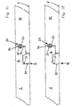
- FIG. 1 The drawing shows a kind of holding profiles of a fastening system 1 is shown in perspective. At the respective opposite narrow side of panels 2 and 3 corresponding holding profiles are provided so that the adjacent panels 2 and 3 can be connected together.
- this type of holding profiles is a modified tongue and groove joint, in which the spring 4 engages behind an undercut in the lower groove wall of the groove 5, so that both panels 2 and 3 laid in the installed state against a pulling in the plane of the laid
- Panels 2 and 3 are secured perpendicular to the direction of the locked narrow sides.
- FIG. 2 shows the oblique attachment of a new panel 2.
- the spring 4 of the new panel 2 is always brought in the direction of arrow P1 with the groove 5 of the laid panel 3 into engagement and the new panel 2 then swung down on the laying surface V until the in FIG. 3 shown situation is reached.
- a curved portion 4a of the cross section of the spring 4 engages behind a recess 5a which is curved in cross-section in the lower groove wall 5b of the groove 5 in such a way that the panels 2 and 3 are prevented from being pushed apart perpendicularly to the locked narrow sides.
- Fastening system 1 is provided, corresponding holding profiles with hook elements 6 and 7 are provided. These have the advantage that they are at the same time with the locking of the according to Figures 1-3 described holding profiles, spring 4 and groove 5, after oblique piecing hooked by a pivoting down of the new panel 2 on the laying substrate V together. Any kind of lateral joining movement is not required for the production of the resulting hook connection 8.
- FIG. 4 shows hook connection 8 device disengaged.
- This example on uneven ground, with air between the panels and the laying substrate V and then when a soft impact sound insulating liner 9 between the panels and laying substrate V is arranged.
- FIG. 4 illustrates the symbolically shown weight 11, as a panel, the hook element facing the laying surface, under the load of a weight 11 in a soft impact sound insulating liner 9 sinks. This results in a height offset 12 on the surface of the panels 2 and 10.
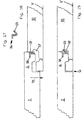
- the Figures 5-10 represent different embodiments of hook connections 8, which are all locked with an additional locking element 13.
- the blocking element 13 prevents the hook connection 8 from moving apart in a direction perpendicular to the plane of the laid panels 2 and 10
- FIG. 4 prevents the additional blocking element 13 a height offset of the hooked panels 2 and 10.
- the blocking element 13 has in the embodiments of Figures 5-10 a rectangular cross section.
- locking grooves 14 and 15 are provided, which are in the hooked state of the hook elements 6 and 7 exactly opposite so that a common locking recess 16 results, in which the blocking element 13 is inserted in a direction perpendicular to the plane of the drawing shown.
- the embodiment according to FIG. 5 shows a free space 17 between the free end of the hook member 7, which faces the laying substrate V, and the narrow side of the associated panel second
- FIGS. 7 and 8 show examples of a hook connection 8, in which an additional blocking element 22 is provided on the narrow side on the freely projecting surface 20 of a hook element 7, which faces the laying substrate V.
- the locking groove 15 is accordingly arranged on a rearward surface 21 of the hook element 6 on the narrow side of the panel 2.
- FIG. 7 shows an example in which the hook elements 6 and 7 have a free space 17 in the region of the locking element 22.
- no free space 17 between the hook elements 6 and 7 is provided in the area of the blocking element 22.
- an undercut connection 18 increases the strength of the hook connection 8 against sliding apart in a direction perpendicular to the plane of the laid panels 2 and 10.
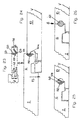
- FIGS. 9 and 10 are shown constructions in which each hook connection 8 is equipped with two locking elements 13 and 22.
- FIG. 9 are the positions of the locking elements 13 and 22 off FIG. 5 and FIG. 7 combined.
- FIG. 10 are the positions of the locking elements 13 and 22 according to FIGS. 6 and 8th combined.
- FIG. 9 is another example of a hook connection 8, in which the laying element V facing the hook element 7 at its free end has a gap 17 to the narrow side of the hook member 6 of the adjacent panel 2, whereas FIG. 10 in the same place an undercut connection 18 provides.
- Locking elements are provided with a round cross-section.
- a locking groove having a semicircular cross-section is integrally formed on the outer free end of the hook element 6, which faces the upper side of the panel 2.
- a locking groove 24 is accordingly attached to a recessed surface 19 of the hook element 7, so that the two locking grooves 23 and 24 together result in a locking recess 25 with a circular cross-section, in which a blocking element 26 is arranged.
- FIG. 12 In FIG. 11 is provided between the laying substrate V facing hook element 7 of a panel 10 and a recessed surface 21 of the hook member 6 on the narrow side of the adjacent panel 2, a free gap 17, whereas according to FIG. 12 an undercut connection 18 is integrated in the same place.
- FIG. 13 is an example that the locking member 27 may be provided at a location where a free gap 17 is provided between the outer free end of the lower hook member 7 and the opposite surface 21 of the corresponding hook member 6.
- An embodiment without clearance 17, with flat abutting flat surfaces and an embodiment with an undercut connection 18 according to the lower hook element 7 of FIG. 12 can also be equipped with a locking recess and a blocking element 27.
- FIG. 14 a particularly strong hook connection 8 is shown in which two locking elements 26 and 27 are used with a circular cross section.
- the locations of the blocking elements 26 and 27 are taken together from the embodiments according to FIG. 11 and FIG. 13 ,
- FIGS. 15 and 16 the laid state of panels 2 and 10 is shown with a finished hook connection 8.
- blocking grooves 30, 31, 32 and 33 are provided in areas which are approximately parallel to the plane of the laid panels.
- the locking grooves 30 and 32 of a hook member 6 and the locking grooves 31 and 33 of the corresponding hook member 7 are arranged so that they are exactly opposite each other and together form a Sperraus foundedung in which a locking element 34 and 35 is arranged.
- the blocking elements 34 and 35 are designed such that they laterally engage in the groove walls of the blocking grooves 30, 31, 32 and 33 fix.
- protruding claw elements 34a and 35a are provided for this purpose on the surface of the locking elements.
- These can also be designed in the manner of barbs, wherein the barbs in the one locking groove 30 and the barbs in the opposite locking groove 31 of the same locking recess are arranged in opposite directions. The same applies to the barbs in the locking grooves 32 and 33.
- FIGS. 17-20 Another embodiment of a hook connection 8 is in the FIGS. 17-20 shown.
- FIG. 17 shows a loose locking element 36 with a resilient latching tab 37, which is widely spread in the illustrated relaxed state.
- FIG. 18 shows the gradual joining of the hook connection 8 in the direction of the arrow P2.
- the blocking element 36 according to FIG. 17 in a groove 38 in the freely protruding surface 38 a of the upper hook element 6 is inserted.
- the resilient latching tab 37 is folded back by the joining movement itself.
- the locking tab 37 of the locking element 36 automatically springs into a locking recess 39 of the corresponding hook element 7.
- the locking tab 37 is spread far less than in her after Fig. 17 shown relaxed position so that it permanently exerts a spring pressure against the locking recess 39 and the hook connection 8 securely locked.
- the blocking element 36 can be used by a laying craftsman as a loose element in the designated groove 38 of the upper hook member 6 or pre-assembled on the hook member 6 by the manufacturer.
- the blocking element 36 may extend over the entire length of the narrow side of a panel or only over part of the length of the narrow side. In the exemplary embodiment, it extends from one end of the narrow side over half its length.
- FIG. 19 is shown that on both sides of the locking tab 37 free spaces are available. These can serve, for example, for the purpose of disassembly of the panels 2 and 10, the locking element 36 with the aid of a pair of needle-nose pliers to pull out of the hook connection 8 and thereby unlock them.
- FIGS. 18 and 19 again show a construction in which the laying substrate V facing hook member 7 at its outer end has a free space 17 to the corresponding hook element 6.
- FIG. 20 A further embodiment of the hook connection with a blocking element, which has an automatic latching tab, is in FIG. 20 shown.
- the only difference to the embodiment after FIGS. 18 and 19 is that the laying substrate V facing hook element 7 of the panel 10 at its free outer end has no clearance 17 to the corresponding hook element 6 of the connected panel 2.
- an undercut connection 18 is again provided, which, like the blocking element 36, prevents the hook connection 8 from moving apart in a direction perpendicular to the plane of the laid-down panels 2 and 10.
- a blocking element in the form of a claw piece 40 which is arranged in the assembled state between engaging behind hook surfaces 41 and 42 of the hook elements 6 and 7.
- the claw piece 40 has claw elements 40 a, which engage in the surface of the hook surfaces 41 and 42 and prevent vertical movement apart of the hook elements 6 and 7.
- a free gap 43 is formed between the engaging behind hook surfaces 41 and 42.
- the claw piece 40 is shown in the assembled state of the hook connection 8.
- the claw piece 40 is fastened in a recess 44 provided for this purpose of the hook element 6 and, beginning at the recess 44, snuggles against the hook element 41 on the hook element 6.
- the recess 44 for the claw piece 40 is arranged on the part of the hook element 6 which engages behind the corresponding hook element 7, the opening of the recess 44 being arranged on a surface 45 of the hook element 6 facing the laying surface.
- the claw piece 40 is bent over in this way, that it projects into the intermediate space 43, which form the hooking surfaces 41 and 42 engaging behind.
- the claw piece 40 is L-shaped prior to assembly.
- a first leg of the L-shaped Krall Cultures inserted in the recess 44 of the hook member 6.
- the second leg is provided with the claw elements and has approximately perpendicular to the narrow side of the panel 10 before mounting away. The latter leg is automatically bent into the space 43 of the engaging behind hook surfaces 41 and 42 during assembly.
- each panel 2 and 10 on its underside facing the laying substrate V undercut Bodenausappel traditions 47 and 48, one of which is arranged in the region of each hook member 6 and 7 on the underside of the panel 2 and 10 respectively.
- a bracket 46 engages in a respective bottom recesses 47 and 48 of two adjacent panels 2 and 10.
- each floor recess 47 and 48 has an undercut.
- the bracket 46 is U-shaped. It is understood that the clip 46 also locks a flat lateral sliding apart at right angles to the hook elements 6 and 7 of the narrow side of the panels 2 and 10 and thus supports the function of the hook connection 8.
- Fig. 23 shows a blocking element 50 with a special cross-section, which in practice by the in Fig. 26 Locking element 51 shown can be replaced.
- the latter blocking element 51 has a simple round cross section.
- Fig. 23 an emptiness Locking groove 52, in which the locking element 51 is captively receivable.
- the captive safety ensures during handling of a panel 2 and during the hooking of the hook connection 8 according to arrow direction P3, that the blocking element 50 does not fall out of the locking groove 52. So that an exchange of the blocking elements 50 and 51 is possible, the locking grooves 52 and 53 provided in the hook elements 6 and 7 are adapted in a particular manner to the geometry of the different blocking elements 50 and 51.
- the blocking element 50 is a development of the in Fig. 17 It has a locking tab 54 which in Fig. 23 is shown in a widely spread relaxed state. On a back 55, the blocking element 50 has a round shape, which is in accordance with Fig. 24 fitting into the locking groove 52 of the hook member 6 inserts.
- the blocking element 50 is provided with holding elements 56 and 57, by means of which it can be secured captively in the blocking groove 52 of the hook element 6.
- the holding elements 56 and 57 also serve to prevent slippage or twisting of the locking element 50 in the locking groove 52 or in the locking recess 58 formed by the locking grooves 52 and 53.
- the holding elements 56 and 57 are formed in the present embodiment as a blunt cam. At the empty locking groove 52 of the Fig.
- the holding elements of the blocking element 50 are designed as barbs or claw elements (Not shown), which can be fixed in a part of the groove wall of the locking groove 52, and hold the locking element 50 captive on the hook element 6.
- the material recesses in the locking groove 52 are not required in this embodiment.
- Fig. 24 shows the joining process of a hook connection 8.
- a panel 2 is namely pivoted down according to arrow P3 on the laying surface V, whereby the hook elements 6 and 7 of the panels 2 and 10 hooked together.
- the locking member 50 is securely held in the locking groove 52 while the hook members are connected in the manner described.
- the locking tab 54 automatically springs into the locking groove 53, which serves as a detent recess and locks the hook connection.
Abstract
Description
Die Erfindung betrifft ein Sperrelement als Zusatz für ein Befestigungssystem für viereckige tafelförmige Paneele, insbesondere Fußbodenpaneele, mit an den Schmalseiten der Paneele angeordneten Halteprofilen, von denen gegenüberliegend angeordnete Halteprofile derart zueinander passen, dass gleichartige Paneele miteinander verbindbar sind, insbesondere für Fußbodenpaneele, mit gegenüberliegend angeordneten ersten Halteprofilen, die so ausgebildet sind, dass an einem in erster Reihe liegenden Paneel in zweiter Reihe ein neues Paneel verriegelbar ist, in dem das neue Paneel zunächst in Schrägstellung relativ zu dem liegenden Paneel an das liegende Paneel angefügt und nachfolgend in die Ebene des liegenden Paneels herabgeschwenkt wird, sowie mit gegenüberliegend angeordneten zweiten Halteprofilen, die korrespondierende Hakenelemente aufweisen, wobei mit einem der Hakenelemente des neuen Paneels und einem Hakenelement eines bereits in zweiter Reihe liegenden Paneels durch das Herabschwenken des neuen Paneels eine Hakenverbindung herstellbar ist, wobei jeder Hakenverbindung ein solches Sperrelement zugeordnet ist, das im verhakten Zustand zweier Paneele ein Lösen der Hakenverbindung in einer Richtung senkrecht zu der Ebene der verlegten Paneele unterbindet.The invention relates to a blocking element as an addition for a fastening system for rectangular tabular panels, in particular floor panels, arranged on the narrow sides of the panels holding profiles, of which oppositely arranged holding profiles match each other so that similar panels are connected to each other, especially for floor panels, arranged opposite first retaining profiles, which are formed so that on a first-row panel in the second row, a new panel is lockable, in which the new panel is first added in an inclined position relative to the lying panel to the lying panel and subsequently in the plane of lying Panels is pivoted down, as well as with oppositely disposed second retaining profiles, which have corresponding hook elements, wherein one of the hook elements of the new panel and a hook element of an already in the second row lying panel through the H swinging down the new panel a hook connection can be produced, each hook connection is associated with such a locking element, which prevents a release of the hook connection in a direction perpendicular to the plane of the laid panels in the hooked state of two panels.
Ein Befestigungssystem ohne zusätzliches Sperrelement ist aus der
Bevorzugt angewendet wird ein derartiges Befestigungssystem für sogenannten Laminatfußboden, der einen Kern aus Holzwerkstoff, wie MDF, HDF oder Spanplattenmaterial aufweist. Die mechanischen Halteprofile sind zumeist an die Schmalseiten von Holzwerkstoffplatten angefräst.Such a fastening system for so-called laminate flooring, which has a core of wood-based material, such as MDF, HDF or chipboard material, is preferably used. The mechanical holding profiles are usually milled to the narrow sides of wood-based panels.
Laminatfußboden wird überwiegend schwimmend verlegt. Zur Minderung von Trittschall wird üblicherweise eine trittschalldämmende Zwischenlage zwischen dem Verlegeuntergrund und den Laminatpaneelen angeordnet. Auch bekannt ist es, dass eine trittschalldämmende Schicht an der dem Verlegeuntergrund zugewandten Unterseite von Laminatpaneelen fest angebracht ist.Laminate flooring is mainly laid floating. In order to reduce impact sound, a padding-sound insulating intermediate layer is usually arranged between the laying substrate and the laminate panels. It is also known that a footfall sound insulating layer is fixedly mounted on the underside facing the laying surface of laminate panels.
Besonders problematisch ist die Hakenverbindung des bekannten Befestigungssystem dann, wenn im Bereich einer Hakenverbindung nur dasjenige Paneel mit einer großen Last beaufschlagt ist, dessen Hakenelement unten liegt, nämlich dem Verlegeuntergrund zugewandt ist. Das mit diesem verhakte obenliegende Hakenelement des benachbarten Paneels ist nicht belastet daher wird durch die Last nur das Paneel mit dem untenliegenden Hakenelement in die zumeist weiche trittschalldämmende Zwischenlage gedrückt. Dabei löst sich das obenliegende Hakenelement des unbelasteten Paneels aus dem untenliegenden Hakenelement des benachbarten Paneels. Die Hakenverbindung ist außer Funktion und die Funktion meist nicht wieder herstellbar.Particularly problematic is the hook connection of the known fastening system when in the region of a hook connection only that panel is subjected to a large load, the hook element is at the bottom, namely facing the laying surface. The hooked with this overhead hook element of the adjacent panel is not loaded therefore is pressed by the load only the panel with the underlying hook element in the mostly soft impact sound insulating liner. In this case, the overhead hook element of the unloaded panel separates from the underlying hook element of the adjacent panel. The hook connection is out of order and the function usually can not be restored.
Nach dem Stand der Technik sind Hinterschneidungen in die Hakenverbindung integriert, durch die ein Lösen der Hakenverbindung senkrecht zur Verlegeebene der Paneele verhindert werden soll. Diese Hinterschneidungen haben sich jedoch als unzureichend erwiesen, dieser Art von Befestigungselementen eine ausreichende Festigkeit zu verleihen.Under the prior art undercuts are in the hook connection integrated, by which a release of the hook connection is to be prevented perpendicular to the laying plane of the panels. However, these undercuts have proven to be insufficient to give this type of fasteners sufficient strength.
Aus der
Ein Sperrelement, das für eine Hakenverbindung von Paneelen vorgeschlagen wird, die nicht durch eine Schwenkbewegung eines der Paneele verhakt werden sollen, ist aus der
Der Erfindung liegt die Aufgabe zugrunde, ein verbessertes Sperrelement vorzuschlagen, das den Problemen des als "Fremdfeder" bekannten Sperrelements abhilft, welches für Paneele vorgesehen ist, die durch eine Schwenkbewegung eines der Paneele verhakt werden.The invention has for its object to propose an improved blocking element, which remedies the problems of known as "foreign spring" blocking element, which is intended for panels that are hooked by a pivoting movement of the panels.
Erfindungsgemäß wird die Aufgabe dadurch gelöst, dass das Sperrelement eine federnde Rastlasche aufweist und derart ausgebildet ist, dass es in einer Sperrnut eines der Hakenelemente eines ersten Paneels anzuordnen ist, wobei eine Sperrnut des zugeordneten Hakenelements der gegenüberliegenden Schmalseite eines zweiten Paneels eine hinterschnittene Rastvertiefung bildet, in die die Rastlasche des Hakenelements des ersten Paneels während der Montage selbsttätig einrastbar ist, und wobei das Sperrelement so ausgebildet ist, dass die Rastlasche im entspannten Zustand von der Schmalseite weit hervorsteht, so dass die Rastlasche während des Herabschwenkens des ersten Paneels in die Ebene der verlegten Paneele mit dem Hakenelement des zweiten Paneels in Berührung kommt und automatisch soweit zurückklappbar ist, dass die Rastlasche an der Schmalseite nicht mehr über das äußere Ende des Hakenelements des ersten Paneels hinausragt.According to the invention the object is achieved in that the blocking element has a resilient latching tab and is designed such that it is to be arranged in a locking groove of the hook elements of a first panel, wherein a locking groove of the associated hook element of the opposite narrow side of a second panel forms an undercut latching recess, in which the locking tab of the hook element of the first panel is automatically latched during assembly, and wherein the Locking element is formed so that the locking tab in the relaxed state of the narrow side protrudes far, so that the locking tab comes during the down pivoting of the first panel in the plane of the laid panels with the hook element of the second panel in touch and is automatically folded back so far that the Stop tab on the narrow side no longer protrudes beyond the outer end of the hook element of the first panel.
Bei dem Sperrelement kann es sich um ein sehr einfaches Bauteil handeln, für das es vielfältige konstruktive Ausgestaltungen gibt. Es kann sich um ein Sperrelement handeln, das an einem der Hakenelemente vormontiert ist, um ein loses Sperrelement, das nach dem Verhaken der Hakenelemente angebracht wird, oder um ein in das Kernmaterial des Paneels integriertes Sperrelement.The blocking element may be a very simple component, for which there are many constructive embodiments. It may be a blocking element preassembled on one of the hook elements, a loose blocking element attached after hooking of the hook elements, or a blocking element integrated in the core material of the panel.
In einer besonders einfachen Ausführung weist jedes der Hakenelemente der gegenüberliegenden Schmalseiten eines Paneels eine Sperrnut auf, die sich in Längsrichtung der Schmalseite erstreckt. Die Sperrnuten zweier Paneele grenzen dabei im verbundenen Zustand der Hakenelemente aneinander und bilden eine gemeinsame Sperrausnehmung. Bei der Profilierung der Hakenelemente mit Fräswerkzeugen lassen sich die Sperrnuten sehr einfach mitfräsen. Hierzu müssen entsprechende Konturen an den Fräswerkzeugen vorgesehen sein.In a particularly simple embodiment, each of the hook elements of the opposite narrow sides of a panel has a locking groove which extends in the longitudinal direction of the narrow side. The locking grooves of two panels adjoin one another in the connected state of the hook elements and form a common locking recess. When profiling the hook elements with milling tools, the locking grooves can be very easily mitfräsen. For this purpose, appropriate contours must be provided on the milling tools.
Wenn die Sperrausnehmung einen runden oder rechteckigen Querschnitt aufweist, hat dies den Vorteil, dass als Sperrelemente besonders kostengünstiges Standardmaterial verwendet werden kann.If the locking recess has a round or rectangular cross-section, this has the advantage that particularly cost-effective standard material can be used as locking elements.
Bevorzugt dann, wenn es sich um ein einfaches Sperrelement mit rundem oder mehreckigem Querschnitt handelt, ist es vorteilhaft, wenn die Sperrnuten an solchen Flächen eines Hakenelements vorgesehen sind, die im verlegten Zustand der Paneele etwa senkrecht zu der Ebene ausgerichtet sind, in der die Paneele verlegt sind.Preferably, when it is a simple blocking element with a round or polygonal cross-section, it is advantageous if the locking grooves are provided on such surfaces of a hook element, which in the installed state of the panels about are aligned perpendicular to the plane in which the panels are laid.
Bei einer weiteren Alternative eines Befestigungssystems ist das Sperrelement in einer Sperrnut eines der Hakenelemente eines ersten Paneels angeordnet und weist eine federnde Rastlasche auf. Dabei bildet eine Sperrnut des zugeordneten Hakenelements der gegenüberliegenden Schmalseite eines zweiten Paneels eine hinterschnittene Rastvertiefung, in der die Rastlasche des Hakenelements des ersten Paneels während der Montage selbsttätig einrastbar ist.In a further alternative of a fastening system, the blocking element is arranged in a locking groove of one of the hook elements of a first panel and has a resilient latching tab. In this case, a locking groove of the associated hook element of the opposite narrow side of a second panel forms an undercut detent recess in which the locking tab of the hook element of the first panel is automatically latched during assembly.
Diese Konstruktion kann einfacherweise mit einem Sperrelement versehen sein, das eine im entspannten Zustand von der Schmalseite weit hervorstehende Rastlasche aufweist, die während des Herabschwenkens eines neuen Paneels in die Ebene der verlegten Paneele mit dem Hakenelement des benachbarten Paneels in Berührung kommt und automatisch soweit zurückgeklappt wird, dass die Rastlasche an der Schmalseite nicht mehr über das äußere Ende des Hakenelements hinausragt. Wenn die Hakenverbindung nahezu ihre Verriegelungsposition erreicht hat, federt die Rastlasche selbsttätig in die Rastvertiefung des Hakenelements des benachbarten Paneels hervor und verriegelt die Hakenverbindung in vertikaler Richtung, nämlich senkrecht zur Ebene der verlegten Paneele.This construction may simply be provided with a blocking element which has a locking tab projecting far in the relaxed state from the narrow side, which comes into contact with the hook element of the adjacent panel during the pivoting down of a new panel in the plane of the laid panels and is automatically folded back as far in that the latching tab on the narrow side no longer protrudes beyond the outer end of the hook element. When the hook connection has almost reached its locking position, the locking tab automatically springs into the locking recess of the hook element of the adjacent panel and locks the hook connection in the vertical direction, namely perpendicular to the plane of the laid panels.
Ein derartig selbsttätiges Rastelement kann in einem der Hakenelemente vormontiert sein oder lose beiliegen, damit es der Verleger selbst während der Verlegung der Paneele an dem dafür vorgesehenen Hakenelement anbringen kann.Such a self-locking element can be pre-assembled in one of the hook elements or loosely attached, so that it can install the publisher even during the installation of the panels on the designated hook element.
Das selbsttätige Sperrelement sowie die Rastvertiefung sind zweckmäßigerweise so ausgebildet, dass das Sperrelement jederzeit mit einem einfachen Werkzeug, beispielsweise einer spitzen Zange leicht in Längsrichtung der Schmalseiten aus der Hakenverbindung herausgezogen werden kann, wenn die Paneele demontiert werden müssen. Dazu ist zu beiden Seiten der Rastlasche ein freier Zwischenraum vorgesehen, damit eine Zange angesetzt werden kann.The automatic locking element and the locking recess are suitably designed so that the locking element can be easily pulled out at any time with a simple tool, such as a sharp pliers in the longitudinal direction of the narrow sides of the hook connection when the panels are dismantled Need to become. For this purpose, a free space is provided on both sides of the locking tab, so that a pair of pliers can be attached.
Der prinzipielle Vorteil der Verriegelung mittels eines einrastenden Sperrelements gegenüber einem einzuschiebenden Sperrelement ist, dass vor der Schmalseite einer Paneelreihe kein Raum benötigt wird, um das Sperrelement an eine Sperrausnehmung anzusetzen und in diese einzuschieben. Ein einzuschiebendes Sperrelement lässt sich nahe einer Wand nicht mehr in eine Sperrausnehmung einfügen, wohingegen das einrastbare Sperrelement problemlos seitlich an eines der Hakenelemente angefügt und durch Herabschwenken eines neuen Paneels verriegelt werden kann.The principal advantage of locking by means of a latching locking element against a blocking element to be inserted is that no space is required in front of the narrow side of a row of panels in order to attach the blocking element to a locking recess and insert it into it. A push-in locking element can no longer be inserted into a locking recess near a wall, whereas the latchable locking element can be easily attached laterally to one of the hook elements and locked by pivoting down a new panel.
Mit einer weiteren nützlichen Verbesserung ist bezweckt, dass in ein und derselben Sperrausnehmung, die durch Sperrnuten zweier Hakenelemente gebildet ist, unterschiedliche Sperrelemente verwendet werden können, die unterschiedliche Geometrien aufweisen und durch unterschiedliche Mechanismen der Verriegelung der Hakenverbindung die erforderliche Festigkeit verleihen. Zu diesem Zweck sind die Sperrnuten und Sperrelemente besonders aufeinander abgestimmt. Dabei ist entweder ein stabförmiges Sperrelement in seiner Längsrichtung in die Sperrausnehmung einschiebbar oder alternativ ein Sperrelement in derselben Sperrausnehmung aufnehmbar, das eine federnde Rastlasche aufweist, wobei dann eine der Sperrnuten eine Halteaufnahme für das mit der Rastlasche versehene Sperrelement bildet und die zugeordnete Sperrnut eine hinterschnittene Rastvertiefung bildet, in die die federnde Rastlasche während der Montage der Hakenverbindung selbsttätig einrastbar ist.Another useful improvement is that in the same locking recess, which is formed by locking grooves of two hook elements, different locking elements can be used, which have different geometries and give the required strength by different mechanisms of locking the hook connection. For this purpose, the locking grooves and locking elements are particularly matched. In this case, either a rod-shaped blocking element in its longitudinal direction in the locking recess can be inserted or alternatively a locking element in the same locking recess receivable having a resilient locking tab, in which case one of the locking grooves forms a retaining receptacle for the locking tab provided with the locking element and the associated locking groove an undercut detent recess forms, in which the resilient locking tab is automatically latched during assembly of the hook connection.
Ein Paneel mit einem erfindungsgemäßen Befestigungssystem weist zwei unterschiedliche Arten miteinander zusammenwirkender Halteprofile auf. Diejenigen Halteprofile, über die die einzelnen Verlegereihen eines Fußbodens miteinander verriegelt,sind, weisen Halteprofile auf, die nach dem Prinzip: Schräges Ansetzen eines neuen Paneels und anschließendes Herabschwenken desselben verriegelt werden. Die hierfür benötigte Art Halteprofil ermöglicht es, ein neues Paneel durch eine scharnierartige Schwenkbewegung an einer verlegten Paneelreihe mechanisch zu verriegeln. Die einzelnen Paneelreihen sind dadurch gegen ebenes Auseinanderziehen in einer Richtung senkrecht zu den verriegelten Halteprofilen gesichert.A panel with a fastening system according to the invention has two different types of holding profiles interacting with one another. Those retaining profiles over which the individual laying rows of a floor are locked together are pointing Holding profiles, which are locked according to the principle: oblique attachment of a new panel and then pivoting down the same. The type of holding profile required for this purpose makes it possible to mechanically lock a new panel by means of a hinge-like pivoting movement on a laid row of panels. The individual rows of panels are thereby secured against level pulling in a direction perpendicular to the locked retaining profiles.
An den übrigen beiden Schmalseiten eines Paneels sind Halteprofile in Form von Hakenelementen angebracht, wobei ein erstes Hakenelement von der Schmalseite hervorsteht und im verlegten Zustand dem Verlegeuntergrund zugewandt ist und das zweite Hakenelement von der Schmalseite hervorsteht und der dekorativen Oberseite des Paneels zugewandt ist. Beide Hakenelemente einer Hakenverbindung sind durch ein zusätzliches Sperrelement gegen ein Auseinanderbewegen senkrecht zur Ebene der verlegten Paneele gesichert.At the other two narrow sides of a panel holding profiles are mounted in the form of hook elements, wherein a first hook element protrudes from the narrow side and facing the installation surface in the installed state and the second hook element protrudes from the narrow side and the decorative top of the panel faces. Both hook elements of a hook connection are secured by an additional blocking element against a movement apart perpendicular to the plane of the laid panels.
Nachstehend ist die Erfindung in einer Zeichnung beispielhaft dargestellt und anhand der Figuren detailliert beschrieben.The invention is illustrated by way of example in a drawing and described in detail with reference to FIGS.
Es zeigen:
- Fig. 1
- eine perspektivische Darstellung eines Halteprofils, das durch schräges Ansetzen eines neuen Paneels und anschließendes Herabsenken in die Verlegeebene mecha- nisch zu verriegeln ist,
- Fig. 2
- das schräge Ansetzen der Halteprofile gemäß
Figur 1 - Fig. 3
- die Halteprofile gemäß
Figur 1 - Fig. 4
- Halteprofile in Form von Hakenelementen gemäß dem Stand der Technik,
- Fig. 5-10
- Ausführungsformen einer Hakenverbindung mit einem oder mehreren zusätzlichen Sperrelementen mit recht- eckigem Querschnitt,
- Fig. 11-14
- eine Konstruktion einer Hakenverbindung mit ei- nem oder mehreren zusätzlichen Sperrelementen, die einen runden Querschnitt aufweisen,
- Fig. 15/16
- Ausführungsformen einer Hakenverbindung mit Sperrelementen, die im verlegten Zustand der Paneele in solche Flächen der Hakenelemente eingelassen sind, die etwa horizontal liegen,
- Fig. 17-20
- eine Ausführungsform einer Hakenverbindung mit einem Sperrelement mit einer federnden Rastlasche, die während der Montage der Hakenverbindung selbsttä- tig in eine zugeordnete Rastvertiefung eingreift
- Fig. 21
- eine Hakenverbindung mit einem als Krallstück ausge- bildeten Sperrelement,
- Fig. 22
- eine Hakenverbindung mit einem als Klammer ausgebil- deten Sperrelement an der Unterseite der Paneele,
- Fig. 23
- ein weiteres Sperrelement mit einer federnden Rast- lasche sowie eine Sperrnut, die zur Aufnahme des Sperrelements angepasst ist,
- Fig. 24
- eine Hakenverbindung mit dem Sperrelement gemäß
Fig. 23 , während des Fügevorgangs, - Fig. 25
- eine Hakenverbindung mit dem Sperrelement gemäß
Fig. 23 im eingerasteten Zustand, - Fig. 26
- eine Hakenverbindung mit denselben Sperrnuten und derselben Sperrausnehmung, wie gemäß
Fig. 25 , wobei das Rastlaschen-Sperrelement ersetzt ist durch ein Sperrelement mit rundem Querschnitt.
- Fig. 1
- 3 is a perspective view of a retaining profile which is to be mechanically locked by obliquely attaching a new panel and then lowering it into the laying plane;
- Fig. 2
- the oblique attachment of the holding profiles according to
FIG. 1 . - Fig. 3
- the holding profiles according to
FIG. 1 in the locked state, - Fig. 4
- Holding profiles in the form of hook elements according to the prior art,
- Fig. 5-10
- Embodiments of a hook connection with one or more additional blocking elements with a rectangular cross-section,
- Fig. 11-14
- a construction of a hook connection with one or more additional blocking elements, which have a round cross-section,
- Fig. 15/16
- Embodiments of a hook connection with locking elements, which are embedded in the installed state of the panels in such areas of the hook elements, which are approximately horizontal,
- Fig. 17-20
- an embodiment of a hook connection with a locking element with a resilient locking tab which engages selbsttä- tig during the assembly of the hook connection in an associated latching recess
- Fig. 21
- a hook connection with a blocking element designed as a claw piece,
- Fig. 22
- a hook connection with a blocking element designed as a clamp on the underside of the panels,
- Fig. 23
- a further blocking element with a resilient latching lug and a locking groove which is adapted to receive the blocking element,
- Fig. 24
- a hook connection with the locking element according to
Fig. 23 during the joining process, - Fig. 25
- a hook connection with the locking element according to
Fig. 23 in the locked state, - Fig. 26
- a hook connection with the same locking grooves and the same locking recess, as in accordance with
Fig. 25 wherein the locking tab locking element is replaced by a blocking element with a round cross section.
Die Ausführungsbeispiele der
Nach
Paneele 2 und 3 und senkrecht zur Richtung der verriegelten Schmalseiten gesichert sind.
An den übrigen Schmalseiten eines Paneels 2 bzw. 3, das mit demAt the remaining narrow sides of a
Befestigungssystem 1 ausgestattet ist, sind korrespondierende Halteprofile mit Hakenelementen 6 und 7 vorgesehen. Diese haben den Vorteil, dass sie sich sozusagen gleichzeitig mit der Verriegelung der gemäß
Die gemäß
Die
In
Die
Gemäß
Gemäß
Im Unterschied zu
Gemäß
In
Eine weitere Ausführungsform einer Hakenverbindung 8 ist in den
Das Sperrelement 36 kann durch einen Verlegehandwerker als loses Element in der dafür vorgesehenen Nut 38 des oberen Hakenelements 6 eingesetzt werden oder herstellerseitig an dem Hakenelement 6 vormontiert sein. Das Sperrelement 36 kann sich über die gesamte Länge der Schmalseite eines Paneels erstrecken oder nur über einen Teil der Länge der Schmalseite. In dem Ausführungsbeispiel erstreckt es sich von einem Ende der Schmalseite über deren halbe Länge.The blocking
In
Die
Eine weitere Ausführungsform der Hakenverbindung mit einem Sperrelement, 36 das eine selbsttätige Rastlasche 37 aufweist, ist in
Eine andere Konstruktion eines Befestigungssystems 1 sieht gemäß
Das Krallstück 40 ist vor der Montage L-förmig ausgebildet. Ein erster Schenkel des L-förmigen Krallstücks steckt in der Ausnehmung 44 des Hakenelements 6. Der zweite Schenkel ist mit den Krallelementen versehen und weist vor der Montage etwa senkrecht von der Schmalseite des Paneels 10 weg. Letzterer Schenkel wird während der Montage automatisch in den Zwischenraum 43 der sich hintergreifenden Hakenflächen 41 und 42 hineingebogen.The claw piece 40 is L-shaped prior to assembly. A first leg of the L-shaped Krallstücks inserted in the
Die in
Das Sperrelement 50 ist eine Weiterbildung des in
- 11
- Befestigungssystemfastening system
- 22
- Paneelpaneling
- 33
- Paneelpaneling
- 44
- Federfeather
- 4a4a
- gekrümmter Bereichcurved area
- 55
- Nutgroove
- 5a5a
- gekrümmte Vertiefungcurved recess
- 5b5b
- untere Nutwandlower groove wall
- 66
- Hakenelementhook element
- 77
- Hakenelementhook element
- 88th
- Hakenverbindunghook connection
- 99
- Trittschall dämmende ZwischenlageImpact sound insulating liner
- 1010
- Paneelpaneling
- 1111
- GewichtWeight
- 1212
- Höhenversatzheight offset
- 1313
- Sperrelementblocking element
- 1414
- Sperrnutlocking groove
- 1515
- Sperrnutlocking groove
- 1616
- Sperrausnehmunglocking recess
- 1717
- Zwischenraumgap
- 1818
- hinterschnittene Verbindungundercut connection
- 1919
- zurückstehende Flächereceding surface
- 2020
- hervorstehende Flächeprotruding surface
- 2121
- zurückstehende Flächereceding surface
- 2222
- Sperrelementblocking element
- 2323
- Sperrnutlocking groove
- 2424
- Sperrnutlocking groove
- 2525
- Sperrausnehmunglocking recess
- 2626
- Sperrelementblocking element
- 2727
- Sperrelementblocking element
- 2828
- Sperrelementblocking element
- 3030
- Sperrnutlocking groove
- 3131
- Sperrnutlocking groove
- 3232
- Sperrnutlocking groove
- 3333
- Sperrnutlocking groove
- 3434
- Sperrelementblocking element
- 34a34a
- KrallelementKrall element
- 3535
- Sperrelementblocking element
- 35a35a
- KrallelementKrall element
- 3636
- Sperrelementblocking element
- 3737
- Rastlaschesnap tab
- 3838
- Nutgroove
- 38a38a
- hervorstehende Flächeprotruding surface
- 3939
- Rastvertiefunglatching depression
- 4040
- Krallstückclaw component
- 40a40a
- KrallelementKrall element
- 4141
- Hakenflächehook surface
- 4242
- Hakenflächehook surface
- 4343
- Zwischenraumgap
- 4444
- Ausnehmungrecess
- 4545
- Flächearea
- 4646
- Klammerclip
- 4747
- Bodenausnehmungbottom recess
- 4848
- Bodenausnehmungbottom recess
- 5050
- Sperrelementblocking element
- 5151
- Sperrelementblocking element
- 5252
- Sperrnutlocking groove
- 5353
- Sperrnutlocking groove
- 5454
- Rastlaschesnap tab
- 5555
- Rückenmove
- 5656
- Halteelementretaining element
- 5757
- Halteelementretaining element
- 5858
- Sperrausnehmunglocking recess
- AA
- Maßmeasure
- BB
- Maßmeasure
- P1P1
- Pfeilrichtungarrow
- P2P2
- Pfeilrichtungarrow
- P3P3
- Pfeilrichtungarrow
- VV
- VerlegeuntergrundSubfloor
Claims (1)
- Locking element (36, 50) as a supplement for use in a fixing system (1) for rectangular, tabular panels (2, 3, 10), particularly floor panels, comprising holding profiles arranged on the narrow side of the panels (2, 3, 10) and of which mutually oppositely arranged holding panels match each other in such a way that like panels (2, 3, 10) are connectible to each other, further comprising mutually oppositely arranged first holding profiles configured in such a way that to a panel (2, 3, 10) installed in a first row a new panel (2) can be locked in a second row by first joining the new panel (2) to the already installed panel (3) in an inclined position with respect to the already installed panel (3) and thereafter turning it down into the plane of the already installed panel (3), further comprising mutually oppositely arranged second holding profiles having corresponding hook elements (6, 7), wherein a hook connection (8) can be established with one of the hook elements (6, 7) of the new panel and a hook element (6, 7) of a panel (3) already installed in a second row by a downward movement of the new panel, wherein such a locking element (36, 50) is assigned to each hook connection (8) and, in the hooked condition of two panels (2, 3, 10), prevents the hook connection (8) from becoming unhooked in a direction vertical to the plane of the already installed panels (2, 3, 10), characterized in that the locking element (36, 50) includes a resilient locking tongue (37,54) and is designed in such a manner that it is intended to be arranged in a locking groove of one of the hook elements (6) of a first panel (2), a locking groove of the associated hook element (7) of the opposite narrow side of a second panel (10) including an undercut locking recess (39, 53) in which the locking tongue (37, 54) of the hook element (6) of the first panel (2) can automatically lock during mounting, and the locking element (36, 50) being designed in such a manner that the locking tongue (37, 54) in the relaxed state protrudes from the narrow side as far that the locking tongue (37, 54) during moving the first panel (2) downwards into the plane of the installed panels comes into contact with the hook element (7) of the second panel (10) and can flap back as far that the locking tongue (37, 54) does no longer protrude over the outer end of the hook element (6) of the first panel.
Priority Applications (7)
| Application Number | Priority Date | Filing Date | Title |
|---|---|---|---|
| EP08100112.5A EP1953309B1 (en) | 2001-08-10 | 2002-07-04 | Fastening system for panels and panel with the fastening system |
| DK10157450.7T DK2194210T3 (en) | 2001-08-10 | 2002-07-04 | Panel and fixing system for panels |
| EP10178642.4A EP2345775B1 (en) | 2001-08-10 | 2002-07-04 | Panel and fastening system for panels |
| DE20222006U DE20222006U1 (en) | 2001-08-10 | 2002-07-04 | Fixing system for panels |
| DK10158660.0T DK2196596T3 (en) | 2001-08-10 | 2002-07-04 | Elements fastening system |
| EP10158660A EP2196596B1 (en) | 2001-08-10 | 2002-07-04 | Fastening system for panels |
| EP10157450.7A EP2194210B1 (en) | 2001-08-10 | 2002-07-04 | Panel and fastening system for panels |
Applications Claiming Priority (2)
| Application Number | Priority Date | Filing Date | Title |
|---|---|---|---|
| DE10138285A DE10138285A1 (en) | 2001-08-10 | 2001-08-10 | Panel and fastening system for panels |
| EP02754315A EP1415056B1 (en) | 2001-08-10 | 2002-07-04 | Panel and fastening system for panels |
Related Parent Applications (2)
| Application Number | Title | Priority Date | Filing Date |
|---|---|---|---|
| EP02754315.6 Division | 2002-07-04 | ||
| EP02754315A Division EP1415056B1 (en) | 2001-08-10 | 2002-07-04 | Panel and fastening system for panels |
Related Child Applications (7)
| Application Number | Title | Priority Date | Filing Date |
|---|---|---|---|
| EP10178642.4A Division EP2345775B1 (en) | 2001-08-10 | 2002-07-04 | Panel and fastening system for panels |
| EP08100112.5A Division EP1953309B1 (en) | 2001-08-10 | 2002-07-04 | Fastening system for panels and panel with the fastening system |
| EP10157450.7A Division EP2194210B1 (en) | 2001-08-10 | 2002-07-04 | Panel and fastening system for panels |
| EP08100112.5 Division-Into | 2008-01-04 | ||
| EP10157450.7 Division-Into | 2010-03-24 | ||
| EP10158660.0 Division-Into | 2010-03-31 | ||
| EP10178642.4 Division-Into | 2010-09-23 |
Publications (4)
| Publication Number | Publication Date |
|---|---|
| EP1669512A2 EP1669512A2 (en) | 2006-06-14 |
| EP1669512A3 EP1669512A3 (en) | 2007-05-09 |
| EP1669512B1 EP1669512B1 (en) | 2011-04-20 |
| EP1669512B9 true EP1669512B9 (en) | 2012-01-04 |
Family
ID=7694376
Family Applications (6)
| Application Number | Title | Priority Date | Filing Date |
|---|---|---|---|
| EP10158660A Expired - Lifetime EP2196596B1 (en) | 2001-08-10 | 2002-07-04 | Fastening system for panels |
| EP06000431A Expired - Lifetime EP1669512B9 (en) | 2001-08-10 | 2002-07-04 | Locking element for use in a hook connection between rectangular, tabular panels |
| EP02754315A Expired - Lifetime EP1415056B1 (en) | 2001-08-10 | 2002-07-04 | Panel and fastening system for panels |
| EP08100112.5A Expired - Lifetime EP1953309B1 (en) | 2001-08-10 | 2002-07-04 | Fastening system for panels and panel with the fastening system |
| EP10157450.7A Expired - Lifetime EP2194210B1 (en) | 2001-08-10 | 2002-07-04 | Panel and fastening system for panels |
| EP10178642.4A Expired - Lifetime EP2345775B1 (en) | 2001-08-10 | 2002-07-04 | Panel and fastening system for panels |
Family Applications Before (1)
| Application Number | Title | Priority Date | Filing Date |
|---|---|---|---|
| EP10158660A Expired - Lifetime EP2196596B1 (en) | 2001-08-10 | 2002-07-04 | Fastening system for panels |
Family Applications After (4)
| Application Number | Title | Priority Date | Filing Date |
|---|---|---|---|
| EP02754315A Expired - Lifetime EP1415056B1 (en) | 2001-08-10 | 2002-07-04 | Panel and fastening system for panels |
| EP08100112.5A Expired - Lifetime EP1953309B1 (en) | 2001-08-10 | 2002-07-04 | Fastening system for panels and panel with the fastening system |
| EP10157450.7A Expired - Lifetime EP2194210B1 (en) | 2001-08-10 | 2002-07-04 | Panel and fastening system for panels |
| EP10178642.4A Expired - Lifetime EP2345775B1 (en) | 2001-08-10 | 2002-07-04 | Panel and fastening system for panels |
Country Status (11)
| Country | Link |
|---|---|
| US (5) | US7451578B2 (en) |
| EP (6) | EP2196596B1 (en) |
| AT (2) | ATE315698T1 (en) |
| CA (1) | CA2456513C (en) |
| DE (7) | DE10138285A1 (en) |
| DK (3) | DK2194210T3 (en) |
| ES (5) | ES2254713T3 (en) |
| PL (3) | PL235591B1 (en) |
| PT (3) | PT1953309T (en) |
| RU (1) | RU2265703C1 (en) |
| WO (1) | WO2003016654A1 (en) |
Cited By (1)
| Publication number | Priority date | Publication date | Assignee | Title |
|---|---|---|---|---|
| US9476208B2 (en) | 2010-04-15 | 2016-10-25 | Spanolux N.V.—Div. Balterio | Floor panel assembly |
Families Citing this family (255)
| Publication number | Priority date | Publication date | Assignee | Title |
|---|---|---|---|---|
| US20020178674A1 (en) | 1993-05-10 | 2002-12-05 | Tony Pervan | System for joining a building board |
| SE9500810D0 (en) | 1995-03-07 | 1995-03-07 | Perstorp Flooring Ab | Floor tile |
| US7131242B2 (en) | 1995-03-07 | 2006-11-07 | Pergo (Europe) Ab | Flooring panel or wall panel and use thereof |
| US7992358B2 (en) | 1998-02-04 | 2011-08-09 | Pergo AG | Guiding means at a joint |
| SE514645C2 (en) | 1998-10-06 | 2001-03-26 | Perstorp Flooring Ab | Floor covering material comprising disc-shaped floor elements intended to be joined by separate joint profiles |
| SE518184C2 (en) | 2000-03-31 | 2002-09-03 | Perstorp Flooring Ab | Floor covering material comprising disc-shaped floor elements which are joined together by means of interconnecting means |
| US8028486B2 (en) | 2001-07-27 | 2011-10-04 | Valinge Innovation Ab | Floor panel with sealing means |
| DE10138285A1 (en) | 2001-08-10 | 2003-03-06 | Akzenta Paneele & Profile Gmbh | Panel and fastening system for panels |
| US8250825B2 (en) | 2001-09-20 | 2012-08-28 | Välinge Innovation AB | Flooring and method for laying and manufacturing the same |
| SE525661C2 (en) | 2002-03-20 | 2005-03-29 | Vaelinge Innovation Ab | Floor boards decorative joint portion making system, has surface layer with underlying layer such that adjoining edge with surface has underlying layer parallel to horizontal plane |
| NZ536142A (en) * | 2002-04-03 | 2006-07-28 | Valinge Innovation Ab | Mechanical locking system for floorboards |
| ES2327502T5 (en) | 2002-04-05 | 2013-03-14 | Tilo Gmbh | Floor boards |
| US8850769B2 (en) | 2002-04-15 | 2014-10-07 | Valinge Innovation Ab | Floorboards for floating floors |
| US7739849B2 (en) | 2002-04-22 | 2010-06-22 | Valinge Innovation Ab | Floorboards, flooring systems and methods for manufacturing and installation thereof |
| AT413228B (en) * | 2002-08-19 | 2005-12-15 | Kaindl M | COVER PLATE |
| DE50309830D1 (en) | 2002-11-15 | 2008-06-26 | Flooring Technologies Ltd | Device consisting of two interconnected construction panels and an insert for locking these building panels |
| AT501440A1 (en) * | 2003-03-07 | 2006-09-15 | Kaindl Flooring Gmbh | COVER PLATE |
| SE0300642D0 (en) | 2003-03-11 | 2003-03-11 | Pergo Europ Ab | Process for sealing a joint |
| SE526688C2 (en) | 2003-11-20 | 2005-10-25 | Pergo Europ Ab | Method of joining panels where a locking rod is inserted into a locking groove or locking cavity |
| US7886497B2 (en) | 2003-12-02 | 2011-02-15 | Valinge Innovation Ab | Floorboard, system and method for forming a flooring, and a flooring formed thereof |
| DE202004000084U1 (en) * | 2004-01-06 | 2004-04-29 | M. Kaindl | Einschwenkprofil |
| EP1555357A1 (en) * | 2004-01-13 | 2005-07-20 | Berry Finance Nv | Floorboard |
| US20050166516A1 (en) | 2004-01-13 | 2005-08-04 | Valinge Aluminium Ab | Floor covering and locking systems |
| AT500407B8 (en) * | 2004-03-23 | 2007-02-15 | Kaindl Flooring Gmbh | CONNECTION PLATE |
| DE102004029233A1 (en) * | 2004-06-17 | 2006-06-08 | Kronospan Technical Co. Ltd., Engomi | Multiposition wall panels |
| SE527570C2 (en) | 2004-10-05 | 2006-04-11 | Vaelinge Innovation Ab | Device and method for surface treatment of sheet-shaped material and floor board |
| US7841144B2 (en) | 2005-03-30 | 2010-11-30 | Valinge Innovation Ab | Mechanical locking system for panels and method of installing same |
| US7454875B2 (en) | 2004-10-22 | 2008-11-25 | Valinge Aluminium Ab | Mechanical locking system for floor panels |
| ES2298664T5 (en) | 2004-10-22 | 2011-05-04 | Välinge Innovation AB | A SET OF SOIL PANELS. |
| US8215078B2 (en) | 2005-02-15 | 2012-07-10 | Välinge Innovation Belgium BVBA | Building panel with compressed edges and method of making same |
| US20130139478A1 (en) | 2005-03-31 | 2013-06-06 | Flooring Industries Limited, Sarl | Methods for packaging floor panels, as well as packed set of floor panels |
| BE1016938A6 (en) | 2005-03-31 | 2007-10-02 | Flooring Ind Ltd | Floor panel manufacturing method, involves providing panels at lower side with guiding groove and providing two opposite sides with profiled edge regions that comprise coupling parts |
| US8061104B2 (en) | 2005-05-20 | 2011-11-22 | Valinge Innovation Ab | Mechanical locking system for floor panels |
| US20060260252A1 (en) * | 2005-05-23 | 2006-11-23 | Quality Craft Ltd. | Connection for laminate flooring |
| US20060260253A1 (en) * | 2005-05-23 | 2006-11-23 | Quality Craft Ltd. | Laminate flooring panel bevel and method of manufacturing same |
| US20070022689A1 (en) * | 2005-07-07 | 2007-02-01 | The Parallax Group International, Llc | Plastic flooring with improved seal |
| SE529076C2 (en) * | 2005-07-11 | 2007-04-24 | Pergo Europ Ab | A joint for panels |
| DE102005037811A1 (en) * | 2005-08-08 | 2007-02-15 | Johannes Schulte | Floor covering made from interlocking rectangular panels, includes edge grooves forming channel into which plastic tongue strip is inserted |
| DE102005059540A1 (en) * | 2005-08-19 | 2007-06-14 | Bauer, Jörg R. | Reliably fastened to each other, flat components, and component |
| DE202005014132U1 (en) * | 2005-09-07 | 2007-01-25 | Tilo Gmbh | Panel for forming e.g. wall surface, has locking unit with locking surfaces on groove and tongue profiles, where height of locking surfaces amounts to be no more than twenty percentage of maximum height of long groove side wall |
| US20070068110A1 (en) * | 2005-09-28 | 2007-03-29 | Bing-Hong Liu | Floor panel with coupling means and methods of making the same |
| US20070130872A1 (en) * | 2005-12-08 | 2007-06-14 | Goodwin Milton W | Wide width lock and fold laminate |
| US8021014B2 (en) * | 2006-01-10 | 2011-09-20 | Valinge Innovation Ab | Floor light |
| SE530653C2 (en) | 2006-01-12 | 2008-07-29 | Vaelinge Innovation Ab | Moisture-proof floor board and floor with an elastic surface layer including a decorative groove |
| DE102006011887A1 (en) | 2006-01-13 | 2007-07-19 | Akzenta Paneele + Profile Gmbh | Blocking element, panel with separate blocking element, method of installing a panel covering of panels with blocking elements, and method and device for pre-assembling a blocking element on a panel |
| SE529506C2 (en) * | 2006-02-03 | 2007-08-28 | Pergo Europ Ab | A joint cover for panels |
| DE102006006124A1 (en) * | 2006-02-10 | 2007-08-23 | Flooring Technologies Ltd. | Device for locking two building panels |
| EP2749710B1 (en) * | 2006-04-14 | 2018-05-23 | Yekalon Industry Inc. | Floor panel and flooring system |
| KR100762943B1 (en) * | 2006-05-19 | 2007-10-02 | 주식회사 한솔홈데코 | Sectional floorings with coupling member and assembling method thereof |
| WO2007136193A1 (en) * | 2006-05-19 | 2007-11-29 | Hansol Home Deco Co., Ltd. | Sectional flooring with coupling member, and assembling method thereof |
| BE1017157A3 (en) | 2006-06-02 | 2008-03-04 | Flooring Ind Ltd | FLOOR COVERING, FLOOR ELEMENT AND METHOD FOR MANUFACTURING FLOOR ELEMENTS. |
| SE533410C2 (en) | 2006-07-11 | 2010-09-14 | Vaelinge Innovation Ab | Floor panels with mechanical locking systems with a flexible and slidable tongue as well as heavy therefore |
| US7861482B2 (en) * | 2006-07-14 | 2011-01-04 | Valinge Innovation Ab | Locking system comprising a combination lock for panels |
| DE102006037614B3 (en) * | 2006-08-10 | 2007-12-20 | Guido Schulte | Floor covering, has head spring pre-assembled in slot and protruding over end of slot, and wedge surface formed at slot or head spring such that head spring runs into wedge surface by shifting projecting end of head spring into slot |
| US8689512B2 (en) * | 2006-11-15 | 2014-04-08 | Valinge Innovation Ab | Mechanical locking of floor panels with vertical folding |
| SE532607C2 (en) * | 2006-11-15 | 2010-03-02 | Vaelinge Innovation Ab | Mechanical locking of vertical paneling floor panels |
| KR101468444B1 (en) | 2006-11-15 | 2014-12-03 | 뵈린게 이노베이션 에이비이 | Mechanical locking of floor panels with vertical folding |
| US11725394B2 (en) | 2006-11-15 | 2023-08-15 | Välinge Innovation AB | Mechanical locking of floor panels with vertical folding |
| DE102006057491A1 (en) * | 2006-12-06 | 2008-06-12 | Akzenta Paneele + Profile Gmbh | Panel and flooring |
| SE531111C2 (en) | 2006-12-08 | 2008-12-23 | Vaelinge Innovation Ab | Mechanical locking of floor panels |
| DE102007002590A1 (en) * | 2007-01-12 | 2008-07-31 | Akzenta Paneele + Profile Gmbh | Panel and flooring |
| DE102007020271A1 (en) | 2007-02-01 | 2008-08-07 | August Hipper | Floor panel connector, has catch lug extending over area of longitudinal edges or front sides of panel, and locking part formed by circumference wall of window, where locking lug or catch lug extends through locking part in locked condition |
| US7984600B2 (en) * | 2007-02-02 | 2011-07-26 | Mohawk Carpet Corporation | Groutless tile system and method for making the same |
| DE202007019298U1 (en) | 2007-02-21 | 2011-10-19 | Hamberger Industriewerke Gmbh | Connection for plate-shaped components |
| DE102007030750B4 (en) * | 2007-04-02 | 2015-01-08 | Hamberger Industriewerke Gmbh | connection |
| DE102007015907B4 (en) | 2007-04-02 | 2011-08-25 | Flooring Technologies Ltd. | System for connecting and locking two building boards, in particular floor panels, and building board, in particular floor panel |
| DE102007026342B4 (en) | 2007-06-06 | 2013-11-28 | Laminatepark Gmbh & Co. Kg | Set of tabular panels with movable locking element |
| DE102007063837B3 (en) | 2007-06-06 | 2020-01-23 | Laminatepark Gmbh & Co. Kg | Set of panel-shaped panels with a movable locking element |
| US20080301945A1 (en) * | 2007-06-08 | 2008-12-11 | Kelly Gibson | Method of forming rectangular panels for use in a panelling system |
| DE202008005295U1 (en) | 2007-08-10 | 2008-10-23 | Hamberger Industriewerke Gmbh | connection |
| DE102007049792A1 (en) | 2007-08-10 | 2009-02-19 | Hamberger Industriewerke Gmbh | connection |
| DE102007042250B4 (en) * | 2007-09-06 | 2010-04-22 | Flooring Technologies Ltd. | Device for connecting and locking two building panels, in particular floor panels |
| DE102007043308B4 (en) | 2007-09-11 | 2009-12-03 | Flooring Technologies Ltd. | Device for connecting and locking two building panels, in particular floor panels |
| US8499521B2 (en) | 2007-11-07 | 2013-08-06 | Valinge Innovation Ab | Mechanical locking of floor panels with vertical snap folding and an installation method to connect such panels |
| US8353140B2 (en) | 2007-11-07 | 2013-01-15 | Valinge Innovation Ab | Mechanical locking of floor panels with vertical snap folding |
| BE1018600A5 (en) | 2007-11-23 | 2011-04-05 | Flooring Ind Ltd Sarl | FLOOR PANEL. |
| US7805903B2 (en) * | 2007-12-13 | 2010-10-05 | Liu David C | Locking mechanism for flooring boards |
| DE102008003550B4 (en) * | 2008-01-09 | 2009-10-22 | Flooring Technologies Ltd. | Device and method for locking two floor panels |
| JP5675369B2 (en) * | 2008-01-31 | 2015-02-25 | ベーリンゲ、イノベイション、アクチボラグVaelinge Innovation Ab | Mechanical locking of floor panels, methods of installing and removing panels, methods and equipment for manufacturing locking systems, methods of connecting displaceable tongues to panels, and tongue blanks |
| US8505257B2 (en) | 2008-01-31 | 2013-08-13 | Valinge Innovation Ab | Mechanical locking of floor panels |
| DE102008021970B4 (en) | 2008-05-02 | 2016-03-24 | Laminatepark Gmbh & Co. Kg | Panel with simplified locking element |
| EP2304126B1 (en) | 2008-05-15 | 2019-07-03 | Välinge Innovation AB | Floor panels with a mechanical locking system activated by a magnetic field |
| DE202008011589U1 (en) * | 2008-09-01 | 2008-11-27 | Akzenta Paneele + Profile Gmbh | Plastic floor panel with mechanical locking edges |
| DE102008047098B3 (en) * | 2008-09-12 | 2010-04-08 | Guido Schulte | flooring |
| DE102008047099B4 (en) * | 2008-09-12 | 2010-05-12 | Guido Schulte | flooring |
| US20100083603A1 (en) * | 2008-10-08 | 2010-04-08 | Goodwin Milton W | Flooring panel with first and second decorative surfaces |
| BE1018389A3 (en) | 2008-12-17 | 2010-10-05 | Unilin Bvba | COMPOSITE ELEMENT, MULTI-LAYER PLATE AND PANEL-SHAPED ELEMENT FOR FORMING SUCH COMPOSITE ELEMENT. |
| US8316612B2 (en) * | 2008-12-18 | 2012-11-27 | Radva Corporation | Pre-insulated structural building panels |
| BE1018627A5 (en) | 2009-01-16 | 2011-05-03 | Flooring Ind Ltd Sarl | FLOOR PANEL. |
| ES2661193T3 (en) * | 2009-01-30 | 2018-03-27 | Välinge Innovation AB | Mechanical floor panel locks and a tongue blank |
| CH700513A2 (en) | 2009-03-10 | 2010-09-15 | Innovaris Ag | Panels. |
| USD656245S1 (en) * | 2009-04-16 | 2012-03-20 | Rene St-Cyr (1996) Inc. | Floor plank |
| BE1018753A3 (en) | 2009-05-11 | 2011-08-02 | Flooring Ind Ltd Sarl | LAMINATE PANEL AND METHODS FOR MANUFACTURING LAMINATE PANELS. |
| NL2003019C2 (en) | 2009-06-12 | 2010-12-15 | 4Sight Innovation Bv | FLOOR PANEL AND FLOOR COVERAGE CONSISING OF MULTIPLE OF SUCH FLOOR PANELS. |
| WO2011014112A1 (en) | 2009-07-31 | 2011-02-03 | Välinge Innovation AB | Methods and arrangements relating to edge machining of building panels |
| US11717901B2 (en) | 2009-07-31 | 2023-08-08 | Valinge Innovation Ab | Methods and arrangements relating to edge machining of building panels |
| JP5714582B2 (en) | 2009-07-31 | 2015-05-07 | ベーリンゲ、イノベイション、アクチボラグVaelinge Innovation Ab | Method and configuration for edge processing of building panels |
| US20110030300A1 (en) * | 2009-08-10 | 2011-02-10 | Liu David C | Floor And Tile With Padding |
| US8365499B2 (en) | 2009-09-04 | 2013-02-05 | Valinge Innovation Ab | Resilient floor |
| US11725395B2 (en) | 2009-09-04 | 2023-08-15 | Välinge Innovation AB | Resilient floor |
| US8646242B2 (en) * | 2009-09-18 | 2014-02-11 | Snap Lock Industries, Inc. | Modular floor tile with connector system |
| DE102009048050B3 (en) * | 2009-10-02 | 2011-01-20 | Guido Schulte | Surface made of mechanical interconnectable elements |
| US8833028B2 (en) | 2010-01-11 | 2014-09-16 | Valinge Innovation Ab | Floor covering with interlocking design |
| EP3702549B1 (en) * | 2010-01-12 | 2023-05-10 | Välinge Innovation AB | Set of floor panels |
| BR112012017589B1 (en) | 2010-01-14 | 2019-11-12 | Spanolux N V Div Balterio | floor panel mounting |
| DE102010004717A1 (en) | 2010-01-15 | 2011-07-21 | Pergo (Europe) Ab | Set of panels comprising retaining profiles with a separate clip and method for introducing the clip |
| US20130255174A1 (en) * | 2010-01-29 | 2013-10-03 | Royal Mouldings, Limited | Siding joinery |
| US8234830B2 (en) | 2010-02-04 | 2012-08-07 | Välinge Innovations AB | Mechanical locking system for floor panels |
| CN102725464B (en) | 2010-02-04 | 2015-01-07 | 瓦林格创新股份有限公司 | Mechanical locking system for floor panels and a tongue therefore |
| BR112012026551A2 (en) | 2010-05-10 | 2016-07-12 | Pergo Europ Ab | panel set |
| BE1019331A5 (en) | 2010-05-10 | 2012-06-05 | Flooring Ind Ltd Sarl | FLOOR PANEL AND METHODS FOR MANUFACTURING FLOOR PANELS. |
| DE102010021436A1 (en) | 2010-05-25 | 2011-12-01 | Hamberger Industriewerke Gmbh | Connection for two panels |
| CA2796588C (en) | 2010-06-03 | 2019-03-19 | Unilin, Bvba | Composed element and corner connection applied herewith. |
| EP2588685B1 (en) | 2010-06-30 | 2020-08-05 | Kreafin Group SA | Panel with improved coupling means |
| US9080329B2 (en) | 2010-10-20 | 2015-07-14 | Kronoplus Technical Ag | Surface covering comprising laminate panels and an extraneous locking element |
| DE202010015754U1 (en) | 2010-11-23 | 2011-01-20 | Akzenta Paneele + Profile Gmbh | Floor panel with soft elastic wear layer |
| DE102010063976B4 (en) * | 2010-12-22 | 2013-01-17 | Akzenta Paneele + Profile Gmbh | paneling |
| US8191328B1 (en) * | 2011-02-04 | 2012-06-05 | Liu David C | Hardwood flooring with sliding locking mechanism |
| US8806832B2 (en) | 2011-03-18 | 2014-08-19 | Inotec Global Limited | Vertical joint system and associated surface covering system |
| EP4050180A1 (en) * | 2011-03-18 | 2022-08-31 | Välinge Innovation AB | Vertical joint system and associated surface covering system |
| SE1150266A1 (en) * | 2011-03-25 | 2012-08-21 | Lindberg Foervaltning Ab P | Wall board with border strip and method of making it |
| UA109705C2 (en) | 2011-04-15 | 2015-09-25 | KIT FOR COVERING A SURFACE CONTAINING PANELS AND EXTERNAL LOCKING ELEMENT | |
| PL2520737T3 (en) * | 2011-05-03 | 2017-08-31 | Barlinek S.A. | Construction panel with a device for connection with at least one further construction panel on a base |
| UA109938C2 (en) | 2011-05-06 | 2015-10-26 | MECHANICAL LOCKING SYSTEM FOR CONSTRUCTION PANELS | |
| US8925264B2 (en) * | 2011-05-09 | 2015-01-06 | Parallax Group International, Llc | Floor tiles with hybrid interlocking system |
| BE1020044A5 (en) | 2011-06-29 | 2013-04-02 | Unilin Bvba | TRAY, TRAY CONSTRUCTION AND METHOD FOR MANUFACTURING A TRAY. |
| UA114715C2 (en) | 2011-07-05 | 2017-07-25 | Сералок Інновейшн Аб | Mechanical locking of floor panels with a glued tongue |
| US9725912B2 (en) | 2011-07-11 | 2017-08-08 | Ceraloc Innovation Ab | Mechanical locking system for floor panels |
| US8650826B2 (en) | 2011-07-19 | 2014-02-18 | Valinge Flooring Technology Ab | Mechanical locking system for floor panels |
| US20130025964A1 (en) * | 2011-07-27 | 2013-01-31 | Armstrong World Industries, Inc. | Sound reducing tongue and groove member sound reducing fabrication process and sound reducing blend |
| DE102012105793A1 (en) | 2011-07-29 | 2013-01-31 | Hamberger Industriewerke Gmbh | Connection for elastic or plate-shaped components and floor covering |
| DE102012102339A1 (en) | 2011-07-29 | 2013-01-31 | Hamberger Industriewerke Gmbh | Connection for elastic or plate-shaped components, profile slides and floor coverings |
| US8769905B2 (en) | 2011-08-15 | 2014-07-08 | Valinge Flooring Technology Ab | Mechanical locking system for floor panels |
| US8857126B2 (en) | 2011-08-15 | 2014-10-14 | Valinge Flooring Technology Ab | Mechanical locking system for floor panels |
| US8763340B2 (en) * | 2011-08-15 | 2014-07-01 | Valinge Flooring Technology Ab | Mechanical locking system for floor panels |
| PL2744952T3 (en) * | 2011-08-15 | 2018-04-30 | Ceraloc Innovation Ab | Mechanical locking system for floor panels |
| DK3115161T3 (en) | 2011-08-29 | 2020-01-27 | Ceraloc Innovation Ab | FLOOR PANEL MECHANICAL LOCKING SYSTEM |
| EP2763850B1 (en) | 2011-10-03 | 2018-07-18 | Unilin, BVBA | Floor panel |
| US8800212B2 (en) | 2011-11-23 | 2014-08-12 | Parallax Group International, Llc | Wall mounting devices |
| DE102011119889A1 (en) | 2011-11-28 | 2013-05-29 | Falquon Gmbh | System for connecting and locking of panels such as floor panel, has projection arranged on long arm of locking element, which is faced in direction opposing to short arm, and is anchored in groove |
| DE202011108752U1 (en) | 2011-12-06 | 2012-01-24 | Akzenta Paneele + Profile Gmbh | Locking system for panels and panel with locking system |
| DE102012013742A1 (en) | 2011-12-19 | 2013-06-20 | Fritz Egger Gmbh & Co. Og | Panel of a floor covering with foreign element |
| DE102011122086A1 (en) | 2011-12-22 | 2013-06-27 | Falquon Gmbh | System for connecting and locking structural panels i.e. floor panels, has side edge comprising groove to accommodate short bracket, another groove formed at another edge and extension formed at long bracket and anchored into latter groove |
| BE1020433A3 (en) | 2012-01-05 | 2013-10-01 | Flooring Ind Ltd Sarl | PANEL. |
| WO2013102804A2 (en) | 2012-01-05 | 2013-07-11 | Flooring Industries Limited, Sarl | Panel |
| BE1022209B1 (en) * | 2012-01-12 | 2016-03-01 | I.V.C. N.V. | FLOOR PANEL |
| WO2013118030A2 (en) | 2012-02-07 | 2013-08-15 | Flooring Industries Limited, Sarl | Floor panel for forming a floor covering, floor covering formed from such floor panels and method for manufacturing such floor panels. |
| EP2814965B1 (en) | 2012-02-16 | 2018-03-21 | Syngenta Participations AG | Engineered pesticidal proteins |
| WO2013136274A1 (en) | 2012-03-13 | 2013-09-19 | University Of Guelph | Myb55 promoter and use thereof |
| RU2615754C2 (en) * | 2012-03-29 | 2017-04-11 | Прокопенко Дмитрий Олегович | Method for finishing panel connection butts treatment |
| US8596013B2 (en) | 2012-04-04 | 2013-12-03 | Valinge Innovation Ab | Building panel with a mechanical locking system |
| US9216541B2 (en) | 2012-04-04 | 2015-12-22 | Valinge Innovation Ab | Method for producing a mechanical locking system for building panels |
| PL3238899T3 (en) | 2012-06-19 | 2020-12-28 | Välinge Innovation AB | Mechanical locking system for floorboards |
| US9140010B2 (en) | 2012-07-02 | 2015-09-22 | Valinge Flooring Technology Ab | Panel forming |
| EP3613920B1 (en) * | 2012-11-22 | 2024-01-31 | Ceraloc Innovation AB | Mechanical locking system for floor panels |
| DE102013101756A1 (en) | 2012-11-30 | 2014-06-05 | Hamberger Industriewerke Gmbh | Connector e.g. glueless connector, for e.g. floor element for flooring applications, has structural element moved to latch position in which locking lip of locking element is non-positively or positively locked in direction |
| US9556620B2 (en) * | 2013-01-11 | 2017-01-31 | Flooring Industries Limited, Sarl | Floor panel for forming a floor covering, floor covering formed of such floor panels, and method for manufacturing such floor panels |
| US9194134B2 (en) | 2013-03-08 | 2015-11-24 | Valinge Innovation Ab | Building panels provided with a mechanical locking system |
| EA201992325A1 (en) | 2013-03-25 | 2020-05-31 | Велинге Инновейшн Аб | FLOOR PANELS EQUIPPED WITH MECHANICAL FIXING SYSTEM AND METHOD FOR PRODUCING SUCH FIXING SYSTEM |
| BE1021833B1 (en) | 2013-05-30 | 2016-01-21 | Flooring Industries Limited Sarl | PANEL |
| WO2014209213A1 (en) | 2013-06-27 | 2014-12-31 | Välinge Innovation AB | Building panel with a mechanical locking system |
| EA031216B1 (en) | 2013-07-09 | 2018-12-28 | Сералок Инновейшн Аб | Set of ceramic or stone tiles |
| DE102013108539A1 (en) | 2013-08-07 | 2015-02-12 | Hamberger Industriewerke Gmbh | Connection and locking element |
| DE102013108538A1 (en) | 2013-08-07 | 2015-02-12 | Hamberger Industriewerke Gmbh | Connection and locking element |
| US9726210B2 (en) | 2013-09-16 | 2017-08-08 | Valinge Innovation Ab | Assembled product and a method of assembling the product |
| KR102250744B1 (en) | 2013-09-16 | 2021-05-10 | 뵈린게 이노베이션 에이비이 | An assembled product and a method of assembling the assembled product |
| CA2926336C (en) | 2013-10-25 | 2022-07-05 | Floor Iptech Ab | Mechanical locking system for floor panels |
| WO2015104680A1 (en) | 2014-01-09 | 2015-07-16 | Flooring Industries Limited, Sarl | Floor panel for forming a floor covering |
| US9714672B2 (en) | 2014-01-10 | 2017-07-25 | Valinge Innovation Ab | Panels comprising a mechanical locking device and an assembled product comprising the panels |
| JP6698024B2 (en) | 2014-01-10 | 2020-05-27 | ベーリンゲ、イノベイション、アクチボラグVaelinge Innovation Ab | Furniture panels |
| WO2015130160A1 (en) * | 2014-02-26 | 2015-09-03 | Innovations 4 Flooring Holding N.V. | Panel interconnectable with similar panels for forming a covering |
| USD928988S1 (en) | 2014-02-26 | 2021-08-24 | I4F Licensing Nv | Panel interconnectable with similar panels for forming a covering |
| RU2764665C2 (en) * | 2014-02-26 | 2022-01-19 | И4Ф Лайсенсинг Нв | Panel with possibility of connection to similar panels to form coating |
| EP2915934A1 (en) | 2014-03-06 | 2015-09-09 | Flooring Industries Ltd., SARL. | Set consisting of panels with a locking element |
| US9260870B2 (en) | 2014-03-24 | 2016-02-16 | Ivc N.V. | Set of mutually lockable panels |
| CN106103862B (en) | 2014-03-24 | 2020-01-10 | 地板工业有限公司 | Set of panels capable of interlocking with each other |
| DK2937490T3 (en) * | 2014-04-26 | 2017-10-16 | René Bangratz | Overlying structure with retaining device |
| CA2946997C (en) | 2014-05-09 | 2022-08-16 | Valinge Innovation Ab | Mechanical locking system for building panels |
| WO2015174914A1 (en) | 2014-05-14 | 2015-11-19 | Välinge Innovation AB | Building panel with a mechanical locking system |
| US10246883B2 (en) | 2014-05-14 | 2019-04-02 | Valinge Innovation Ab | Building panel with a mechanical locking system |
| US20160009475A1 (en) * | 2014-07-09 | 2016-01-14 | General Electric Company | Water heater appliance |
| DE102015106035A1 (en) | 2014-07-31 | 2016-02-04 | Hamberger Industriewerke Gmbh | Connection for plate-shaped components and spring |
| FR3024990B1 (en) | 2014-08-25 | 2018-11-16 | Gerflor | FLOOR PANEL FOR REALIZING A COATING. |
| HUE061045T2 (en) | 2014-08-29 | 2023-05-28 | Vaelinge Innovation Ab | Vertical joint system for a surface covering panel |
| MY183052A (en) | 2014-11-27 | 2021-02-09 | Valinge Innovation Ab | Mechanical locking system for floor panels |
| PT3031998T (en) * | 2014-12-08 | 2017-12-29 | Innovations4Flooring Holding N V | Panel with a hook-like locking system |
| RU2741833C2 (en) | 2014-12-12 | 2021-01-29 | Зингента Партисипейшнс Аг | Compositions and methods for controlling plant pests |
| DK3234380T3 (en) | 2014-12-19 | 2019-11-25 | Vaelinge Innovation Ab | PANELS INCLUDING A MECHANICAL LOCKING DEVICE |
| EP3237704B1 (en) | 2014-12-22 | 2019-11-20 | Ceraloc Innovation AB | Set of identical floor panels provided with a mechanical locking system |
| WO2016113676A1 (en) * | 2015-01-15 | 2016-07-21 | Flooring Industries Limited, Sarl | Floor panel for forming a floor covering |
| BE1022985B1 (en) | 2015-01-16 | 2016-10-27 | Flooring Industries Limited Sarl | Floor panel for forming a floor covering |
| EP3247844B1 (en) | 2015-01-16 | 2022-03-16 | Ceraloc Innovation AB | Mechanical locking system for floor panels |
| US10309113B2 (en) * | 2015-01-16 | 2019-06-04 | Flooring Industries Limited, Sarl | Floor panel for forming a floor covering |
| RU2653207C2 (en) * | 2015-01-22 | 2018-05-07 | Барлинек С.А. | Structural panels with internal compensation gaps |
| DE202015101572U1 (en) * | 2015-03-27 | 2015-04-21 | Guido Schulte | Coating of composite rectangular or square panels |
| US10670064B2 (en) | 2015-04-21 | 2020-06-02 | Valinge Innovation Ab | Panel with a slider |
| WO2016175701A1 (en) | 2015-04-30 | 2016-11-03 | Välinge Innovation AB | Panel with a fastening device |
| EP3473783B1 (en) | 2015-05-12 | 2020-07-08 | Aladdin Manufacturing Corporation | Method for manufacturing floor boards |
| BR112018005338B1 (en) | 2015-09-22 | 2023-03-21 | Välinge Innovation AB | ASSEMBLY OF PANELS COMPRISING A MECHANICAL LOCKING DEVICE AND ASSEMBLED FURNITURE PRODUCT COMPRISING THE PANELS |
| BE1023545B1 (en) * | 2015-10-23 | 2017-04-28 | Flooring Industries Limited, Sarl | Set of floor panels for forming a floor covering |
| MX2018006522A (en) | 2015-12-03 | 2018-11-29 | Vaelinge Innovation Ab | Panels comprising a mechanical locking device and an assembled product comprising the panels. |
| EP3390744A4 (en) | 2015-12-17 | 2019-07-31 | Välinge Innovation AB | A method for producing a mechanical locking system for panels |
| EP3192934A1 (en) | 2016-01-14 | 2017-07-19 | Akzenta Paneele + Profile GmbH | Panel element |
| BE1023818B1 (en) | 2016-01-15 | 2017-08-01 | Flooring Industries Limited Sarl | Floor panel for forming a floor covering |
| DE102016114226A1 (en) | 2016-01-22 | 2017-07-27 | Hamberger Industriewerke Gmbh | Connection for elastic or solid components |
| DE102016114221A1 (en) | 2016-01-22 | 2017-07-27 | Hamberger Industriewerke Gmbh | Connection for components |
| WO2017131574A1 (en) | 2016-01-26 | 2017-08-03 | Välinge Innovation AB | Panels comprising a mechanical locking device and an assembled product comprising the panels |
| CA3011591A1 (en) | 2016-02-04 | 2017-08-10 | Valinge Innovation Ab | A set of panels for an assembled product |
| BR112018014107A2 (en) | 2016-02-09 | 2018-12-11 | Vaelinge Innovation Ab | set of three panel-shaped elements |
| EP3414462B1 (en) | 2016-02-09 | 2020-10-07 | Välinge Innovation AB | Element and method for providing dismantling groove |
| JP6921834B2 (en) | 2016-02-15 | 2021-08-18 | ベーリンゲ、イノベイション、アクチボラグVaelinge Innovation Ab | How to form panels for furniture products |
| CN109312567B (en) | 2016-06-29 | 2021-06-01 | 瓦林格创新股份有限公司 | Method and device for inserting a tongue |
| JP7053506B2 (en) | 2016-06-29 | 2022-04-12 | ベーリンゲ、イノベイション、アクチボラグ | Methods and equipment for inserting tongues |
| CN109415906B (en) | 2016-06-29 | 2021-11-05 | 瓦林格创新股份有限公司 | Method and apparatus for managing and separating a tongue from a tongue blank |
| EP3478468B1 (en) | 2016-06-30 | 2021-05-26 | Välinge Innovation AB | Device for inserting a tongue |
| MX2019003403A (en) | 2016-09-30 | 2019-05-30 | Vaelinge Innovation Ab | Set of panels assembled by vertical displacement and locked together in the vertical and horizontal direction. |
| AU2016426183B2 (en) | 2016-10-11 | 2021-08-05 | Core Innovations Limited | Engineered flooring product and method of manufacturing thereof |
| EP3532737A4 (en) | 2016-10-27 | 2020-04-01 | Välinge Innovation AB | Set of panels with a mechanical locking device |
| JP6999674B2 (en) | 2016-12-22 | 2022-01-18 | ベーリンゲ、イノベイション、アクチボラグ | A device for inserting the tongue into the insertion groove of the panel |
| US10400458B1 (en) * | 2017-02-10 | 2019-09-03 | David W Moeller | Interlocking flooring system using locking strips |
| NL2018781B1 (en) | 2017-04-26 | 2018-11-05 | Innovations4Flooring Holding N V | Panel and covering |
| US11506235B2 (en) | 2017-05-15 | 2022-11-22 | Valinge Innovation Ab | Elements and a locking device for an assembled product |
| EP3420158B1 (en) * | 2017-05-18 | 2020-01-22 | Falquon GmbH | Device for locking two floor panels |
| BR112020012030B1 (en) | 2017-12-22 | 2023-11-21 | Välinge Innovation AB | PANEL SET |
| LT3728869T (en) | 2017-12-22 | 2023-04-25 | Välinge Innovation AB | A set of panels, a method for assembly of the same and a locking device for a furniture product |
| NL2020255B1 (en) | 2018-01-09 | 2019-07-15 | Innovations4Flooring Holding N V | Panel, in particular a floor panel or wall panel |
| NL2020254B1 (en) | 2018-01-09 | 2019-07-15 | Innovations4Flooring Holding N V | Tile, in particular carpet tile, and covering of such tiles |
| EA039273B1 (en) | 2018-01-09 | 2021-12-27 | Велинге Инновейшн Аб | Set of panels |
| BE1026099B1 (en) | 2018-03-16 | 2019-10-14 | Kreafin Group Sa | PANEL OF WHICH THE COUPLING DEVICES ARE SUITABLE FOR CONNECTING THE LONG SIDE AND / OR KOPSE SIDE TOGETHER |
| US11365545B2 (en) * | 2018-01-22 | 2022-06-21 | Inovame | Method of manufacturing a plastic covering panel and the panel obtained |
| US10736416B2 (en) | 2018-03-23 | 2020-08-11 | Valinge Innovation Ab | Panels comprising a mechanical locking device and an assembled product comprising the panels |
| US10799965B2 (en) * | 2018-04-09 | 2020-10-13 | Robert Bosch Tool Corporation | Extendable rails for table saw |
| CA3096995A1 (en) | 2018-04-18 | 2019-10-24 | Valinge Innovation Ab | Set of panels with a mechanical locking device |
| US11536307B2 (en) | 2018-04-18 | 2022-12-27 | Valinge Innovation Ab | Symmetric tongue and t-cross |
| EP3781824B1 (en) | 2018-04-18 | 2024-04-10 | Välinge Innovation AB | Set of panels with a mechanical locking device |
| WO2019203721A1 (en) | 2018-04-18 | 2019-10-24 | Välinge Innovation AB | Set of panels with a mechanical locking device |
| US11614114B2 (en) | 2018-04-19 | 2023-03-28 | Valinge Innovation Ab | Panels for an assembled product |
| EP3807475B1 (en) | 2018-06-13 | 2023-11-15 | Ceraloc Innovation AB | A flooring system provided with a connecting system and an associated connecting device |
| JP2021535330A (en) | 2018-08-30 | 2021-12-16 | ベーリンゲ、イノベイション、アクチボラグVaelinge Innovation Ab | A set of panels with a mechanical locking device |
| KR20210110687A (en) | 2019-01-10 | 2021-09-08 | 뵈린게 이노베이션 에이비이 | Set of vertically unlockable panels, method and device thereof |
| CN117325221A (en) | 2019-03-05 | 2024-01-02 | 塞拉洛克创新股份有限公司 | Method for forming grooves in a panel element and related panel |
| CN113646494A (en) | 2019-03-25 | 2021-11-12 | 塞拉洛克创新股份有限公司 | Mineral-based panel comprising a groove and method for forming a groove |
| DE202019101807U1 (en) | 2019-03-29 | 2019-05-06 | Akzenta Paneele + Profile Gmbh | paneling |
| EP3718437A1 (en) | 2019-04-05 | 2020-10-07 | Välinge Innovation AB | Method for assembling a piece of furniture |
| EP3798385A1 (en) | 2019-09-24 | 2021-03-31 | Välinge Innovation AB | Building panel |
| AU2020415200A1 (en) | 2019-12-27 | 2022-06-09 | Ceraloc Innovation Ab | A thermoplastic-based building panel comprising a balancing layer |
| BE1026833B1 (en) | 2020-04-21 | 2021-07-02 | Flooring Ind Ltd Sarl | Panel |
| EP3971365A1 (en) | 2020-09-17 | 2022-03-23 | Surface Technologies GmbH & Co. KG | Panel |
| EP3971364A1 (en) | 2020-09-17 | 2022-03-23 | Surface Technologies GmbH & Co. KG | Panel |
| EP3971366A1 (en) | 2020-09-17 | 2022-03-23 | Surface Technologies GmbH & Co. KG | Panel |
| CN113187123B (en) * | 2021-04-07 | 2022-07-26 | 中建八局第二建设有限公司 | AAC (autoclaved aerated concrete) panel wall capable of being installed quickly and construction method thereof |
| WO2022224086A1 (en) | 2021-04-21 | 2022-10-27 | Flooring Industries Limited, Sarl | Decorative panel and method for manufacturing a decorative panel |
| EP4079527A1 (en) | 2021-04-21 | 2022-10-26 | Flooring Industries Limited, SARL | Decorative panel and method for manufacturing a decorative panel |
| EP4129711A1 (en) | 2021-08-05 | 2023-02-08 | Flooring Industries Limited, SARL | Method for manufacturing a product comprising a decorative surface layer |
| WO2023154887A1 (en) | 2022-02-11 | 2023-08-17 | Northeast Agricultural University | Methods and compositions for increasing protein and/or oil content and modifying oil profile in a plant |
Family Cites Families (117)
| Publication number | Priority date | Publication date | Assignee | Title |
|---|---|---|---|---|
| BE418853A (en) | ||||
| DE7402354U (en) | 1974-05-30 | Vaw Leichtmetall Gmbh | Securing device for panels | |
| BE417526A (en) | ||||
| US623562A (en) * | 1899-04-25 | Parquetry | ||
| US338653A (en) * | 1886-03-23 | Thied to sam gibbs | ||
| US753791A (en) * | 1903-08-25 | 1904-03-01 | Elisha J Fulghum | Method of making floor-boards. |
| US890436A (en) * | 1907-10-11 | 1908-06-09 | Christian Momberg | Matched flooring. |
| US1723306A (en) * | 1927-08-02 | 1929-08-06 | Harry E Sipe | Resilient attaching strip |
| US1776188A (en) * | 1928-07-12 | 1930-09-16 | Langbaum Maurice | Furniture pad |
| US1854396A (en) * | 1931-03-18 | 1932-04-19 | Structural Gypsum Corp | Gypsum lumber |
| BE398364A (en) * | 1932-09-13 | |||
| US2138085A (en) * | 1935-03-11 | 1938-11-29 | Wood Mosaic Co Inc | Portable composite floor |
| CH200949A (en) | 1937-12-03 | 1938-11-15 | Ferdinand Baechi | Process for the production of floors and soil produced by this method. |
| US2381469A (en) * | 1943-08-21 | 1945-08-07 | Carroll V Sweet | Building panel |
| US2430200A (en) * | 1944-11-18 | 1947-11-04 | Nina Mae Wilson | Lock joint |
| US2644553A (en) * | 1947-06-05 | 1953-07-07 | Walton W Cushman | Panel fastening means |
| US2740167A (en) * | 1952-09-05 | 1956-04-03 | John C Rowley | Interlocking parquet block |
| US3040388A (en) * | 1959-09-04 | 1962-06-26 | George T Conn | Knockdown portable dance floor |
| US3172508A (en) * | 1962-01-19 | 1965-03-09 | Fenestra Inc | Interlocking structural unit |
| US3192574A (en) * | 1962-10-22 | 1965-07-06 | Admiral Chair Company | Temporary floor construction |
| US3175476A (en) * | 1963-04-29 | 1965-03-30 | Fenestra Inc | Locking bar for auxiliary landing mat |
| US3200553A (en) * | 1963-09-06 | 1965-08-17 | Forrest Ind Inc | Composition board flooring strip |
| US3310919A (en) * | 1964-10-02 | 1967-03-28 | Sico Inc | Portable floor |
| US3347048A (en) * | 1965-09-27 | 1967-10-17 | Coastal Res Corp | Revetment block |
| US3526420A (en) * | 1968-05-22 | 1970-09-01 | Itt | Self-locking seam |
| US3579941A (en) * | 1968-11-19 | 1971-05-25 | Howard C Tibbals | Wood parquet block flooring unit |
| SE319199B (en) | 1968-12-20 | 1970-01-12 | P Kihlstedt | |
| SE515324C2 (en) * | 2000-06-22 | 2001-07-16 | Tarkett Sommer Ab | Floor board with connecting means |
| US3657852A (en) * | 1969-09-15 | 1972-04-25 | Walter J Worthington | Floor tiles |
| DE2108141A1 (en) * | 1970-02-20 | 1971-09-30 | Bruun & Soerensen A/S, Aarhus (Dänemark) | Floor construction |
| DK122829B (en) * | 1970-05-01 | 1972-04-17 | P Bruun | Assembly of at least two building parts and method of manufacturing this assembly. |
| US3673751A (en) * | 1970-07-21 | 1972-07-04 | Champion Inc | Building and swimming pool construction |
| BE765817A (en) | 1971-04-16 | 1971-09-16 | Fyens Constantinus F | IMPROVEMENT TO TRIM PANELS. |
| CH562377A5 (en) | 1971-11-29 | 1975-05-30 | Hebgen Heinrich | Form-locked building panel joint connection - with shaped end of one fitting into lipped rounded edge channel of next |
| DE2159042C3 (en) | 1971-11-29 | 1974-04-18 | Heinrich 6700 Ludwigshafen Hebgen | Insulating board, in particular made of rigid plastic foam |
| ZA734151B (en) * | 1972-06-23 | 1974-06-26 | Celtic Ind Ltd & Co Kg | Building elements |
| US3988187A (en) * | 1973-02-06 | 1976-10-26 | Atlantic Richfield Company | Method of laying floor tile |
| DE2502992A1 (en) | 1975-01-25 | 1976-07-29 | Geb Jahn Helga Tritschler | Interlocking tent or other temporary floor panels - flat-surfaced with opposite shaped and counter-shaped bent sections |
| US4416097A (en) * | 1976-02-20 | 1983-11-22 | Weir Richard L | Universal beam construction system |
| US4169688A (en) * | 1976-03-15 | 1979-10-02 | Sato Toshio | Artificial skating-rink floor |
| DE2616077A1 (en) | 1976-04-13 | 1977-10-27 | Hans Josef Hewener | Connecting web with flange for parquet floor - has pliable connecting web with flange held in floor plates to accommodate expansion and shrinking stresses |
| US4094090A (en) * | 1977-02-11 | 1978-06-13 | Walmer Harry E | Doll house |
| SE415915B (en) * | 1979-02-16 | 1980-11-10 | Moelnlycke Ab | COUPLING |
| US4426820A (en) * | 1979-04-24 | 1984-01-24 | Heinz Terbrack | Panel for a composite surface and a method of assembling same |
| DE7928703U1 (en) | 1979-10-09 | 1981-07-02 | Terbrack Kunststoff GmbH & Co KG, 4426 Vreden | PLATE FOR A PLAYING AREA COMPOSABLE FROM THESE PLATES |
| DE2917025A1 (en) | 1979-04-26 | 1980-11-27 | Reynolds Aluminium France S A | Detachable thin panel assembly - has overlapping bosses formed in edge strips and secured by clamping hook underneath |
| EP0024360A1 (en) | 1979-08-16 | 1981-03-04 | Rütgerswerke Aktiengesellschaft | Cladding element for façade surfaces |
| US4316351A (en) * | 1980-05-27 | 1982-02-23 | Ting Raymond M L | Thermally insulated building construction panel and a wall formed from such panels |
| DE3041781A1 (en) | 1980-11-05 | 1982-06-24 | Terbrack Kunststoff GmbH & Co KG, 4426 Vreden | Skating or bowling rink tongue and groove panels - have tongue kink fitting trapezoid or half trapezium groove recess |
| US4449346A (en) * | 1980-11-12 | 1984-05-22 | Tremblay J Gerard | Panel assembly |
| DE3117605A1 (en) | 1981-05-05 | 1982-11-25 | Gruber & Weber, 7562 Gernsbach | Floor-laying part |
| EP0085196A1 (en) | 1982-01-29 | 1983-08-10 | JANSSEN & FRITSEN B.V. | Couplable mat |
| SE450141B (en) * | 1982-12-03 | 1987-06-09 | Jan Carlsson | DEVICE FOR CONSTRUCTION OF BUILDING PLATES EXV FLOOR PLATES |
| DK149498C (en) * | 1983-04-07 | 1986-12-01 | Inter Ikea As | CLOTHING OF BREADS FOR EX. FLOORS OR PANELS |
| DE3343601A1 (en) | 1983-12-02 | 1985-06-13 | Bütec Gesellschaft für bühnentechnische Einrichtungen mbH, 4010 Hilden | Joining arrangement for rectangular boards |
| DE3560797D1 (en) | 1984-03-26 | 1987-11-26 | Gilbert O Rousseau | Decorative panel |
| AU566257B2 (en) | 1985-01-10 | 1987-10-15 | Hockney Pty Ltd | Table top for lorry |
| IT208464Z2 (en) * | 1985-05-10 | 1988-05-28 | Giben Impianti Spa | PRESSER FOR PANEL CUTTING MACHINES OF WOODEN PANELS AND OTHER MATERIAL EQUIPPED WITH TWO PRESSING BODIES WITH INDEPENDENT OPERATION |
| US4819932A (en) * | 1986-02-28 | 1989-04-11 | Trotter Jr Phil | Aerobic exercise floor system |
| US4741136A (en) * | 1986-10-08 | 1988-05-03 | Thompson Gerald M | Edge fastener for caulkless jointed panels |
| US4807416A (en) * | 1988-03-23 | 1989-02-28 | Council Of Forest Industries Of British Columbia Plywood Technical Centre | Tongue and groove profile |
| US5086599A (en) * | 1990-02-15 | 1992-02-11 | Structural Panels, Inc. | Building panel and method |
| DE9004451U1 (en) | 1990-04-19 | 1990-06-28 | Villeroy & Boch Ag, 6642 Mettlach, De | |
| CA2036029C (en) * | 1991-02-08 | 1994-06-21 | Alexander V. Parasin | Tongue and groove profile |
| US5348778A (en) * | 1991-04-12 | 1994-09-20 | Bayer Aktiengesellschaft | Sandwich elements in the form of slabs, shells and the like |
| DE4122099C1 (en) | 1991-04-12 | 1992-10-01 | Bayer Ag, 5090 Leverkusen, De | |
| CH684544A5 (en) | 1992-03-25 | 1994-10-14 | Swifloor Sa | Plate for coverings, particularly for heavy-duty floor coverings, and with this record produced paving. |
| DE4215273C2 (en) | 1992-05-09 | 1996-01-25 | Dietmar Groeger | Covering for covering floor, wall and / or ceiling surfaces, in particular in the manner of a belt floor |
| US5295341A (en) * | 1992-07-10 | 1994-03-22 | Nikken Seattle, Inc. | Snap-together flooring system |
| US5363616A (en) * | 1992-08-13 | 1994-11-15 | Diston Industries, Inc. | Adjustable corner mullion for joining building panels |
| US5283102A (en) * | 1992-10-28 | 1994-02-01 | Premier Wood Floors | Laminated wood flooring product and wood floor |
| US5274979A (en) * | 1992-12-22 | 1994-01-04 | Tsai Jui Hsing | Insulating plate unit |
| SE9301595L (en) * | 1993-05-10 | 1994-10-17 | Tony Pervan | Grout for thin liquid hard floors |
| US20020178674A1 (en) * | 1993-05-10 | 2002-12-05 | Tony Pervan | System for joining a building board |
| JPH0748879A (en) * | 1993-08-05 | 1995-02-21 | Takeshige Shimonohara | Connecting method and connecting structure for member |
| IT1267884B1 (en) | 1994-11-29 | 1997-02-18 | Alberto Giordani | MODULAR INSULATING THERMO-ACOUSTIC SHOCK ABSORBER PANEL WITH QUICK ASSEMBLY AND MANUFACTURING METHOD OF THE SAME. |
| SE503917C2 (en) * | 1995-01-30 | 1996-09-30 | Golvabia Ab | Device for joining by means of groove and chip of adjacent pieces of flooring material and a flooring material composed of a number of smaller pieces |
| DE19503948A1 (en) | 1995-02-07 | 1996-08-08 | Bub Frank Martin | Structural element for covering wall or floor tiles, e.g. in bathrooms, shower rooms etc. |
| US6421970B1 (en) * | 1995-03-07 | 2002-07-23 | Perstorp Flooring Ab | Flooring panel or wall panel and use thereof |
| SE9500810D0 (en) * | 1995-03-07 | 1995-03-07 | Perstorp Flooring Ab | Floor tile |
| SE502994E (en) * | 1995-03-07 | 1999-04-28 | Perstorp Flooring Ab | Floorboard with groove and springs and supplementary locking means |
| US5618602A (en) * | 1995-03-22 | 1997-04-08 | Wilsonart Int Inc | Articles with tongue and groove joint and method of making such a joint |
| GB9516752D0 (en) | 1995-08-16 | 1995-10-18 | Lawborough Consultants | Improvements in or relating to seabed enclosures |
| US5630304A (en) * | 1995-12-28 | 1997-05-20 | Austin; John | Adjustable interlock floor tile |
| BE1010487A6 (en) | 1996-06-11 | 1998-10-06 | Unilin Beheer Bv | FLOOR COATING CONSISTING OF HARD FLOOR PANELS AND METHOD FOR MANUFACTURING SUCH FLOOR PANELS. |
| SE509059C2 (en) * | 1996-12-05 | 1998-11-30 | Valinge Aluminium Ab | Method and equipment for making a building board, such as a floorboard |
| US5797237A (en) * | 1997-02-28 | 1998-08-25 | Standard Plywoods, Incorporated | Flooring system |
| DE19709641C2 (en) * | 1997-03-08 | 2002-05-02 | Akzenta Paneele & Profile Gmbh | Surface covering made of tabular panels |
| US5921047A (en) * | 1997-03-24 | 1999-07-13 | Walker; Marshall P. | Building structure having prefabricated interfitting structural parts |
| DK0874105T3 (en) * | 1997-04-22 | 2004-12-13 | Mondo Spa | Laminated flooring, especially for athletics facilities |
| US6324809B1 (en) * | 1997-11-25 | 2001-12-04 | Premark Rwp Holdings, Inc. | Article with interlocking edges and covering product prepared therefrom |
| US6215485B1 (en) * | 1998-04-03 | 2001-04-10 | Avid Technology, Inc. | Storing effects descriptions from a nonlinear editor using field chart and/or pixel coordinate data for use by a compositor |
| SE512290C2 (en) * | 1998-06-03 | 2000-02-28 | Valinge Aluminium Ab | Locking system for mechanical joining of floorboards and floorboard provided with the locking system |
| SE514645C2 (en) * | 1998-10-06 | 2001-03-26 | Perstorp Flooring Ab | Floor covering material comprising disc-shaped floor elements intended to be joined by separate joint profiles |
| SE513189C2 (en) * | 1998-10-06 | 2000-07-24 | Perstorp Flooring Ab | Vertically mountable floor covering material comprising sheet-shaped floor elements which are joined together by means of separate joint profiles |
| SE515789C2 (en) * | 1999-02-10 | 2001-10-08 | Perstorp Flooring Ab | Floor covering material comprising floor elements which are intended to be joined vertically |
| AU6296699A (en) * | 1998-10-09 | 2000-05-01 | American Structural Composites, Inc. | Composite structural building panels and connection systems |
| DE19851200C1 (en) * | 1998-11-06 | 2000-03-30 | Kronotex Gmbh Holz Und Kunstha | Floor panel has a tongue and groove joint between panels with additional projections and recesses at the underside of the tongue and the lower leg of the groove for a sealed joint with easy laying |
| FR2785633B1 (en) * | 1998-11-09 | 2001-02-09 | Valerie Roy | COVERING PANEL FOR PARQUET, WOODEN PANEL OR THE LIKE |
| US6397548B1 (en) * | 1998-11-19 | 2002-06-04 | Apa-The Engineered Wood Association | Radius tongue and groove profile |
| US6098365A (en) * | 1998-11-19 | 2000-08-08 | Apa - The Engineered Wood Association | Radius tongue and groove profile |
| US6122879A (en) * | 1999-04-07 | 2000-09-26 | Worldwide Refrigeration Industries, Inc. | Snap together insulated panels |
| DE19929896B4 (en) | 1999-06-30 | 2009-07-30 | Akzenta Paneele + Profile Gmbh | Fixing system for panels |
| PT1190149E (en) * | 1999-06-30 | 2005-01-31 | Akzenta Paneele & Profile Gmbh | PANEL WELL AS FIXING SYSTEM FOR PANELS |
| DE29911462U1 (en) * | 1999-07-02 | 1999-11-18 | Akzenta Paneele & Profile Gmbh | Fastening system for panels |
| EP1133841B1 (en) * | 1999-09-29 | 2008-05-14 | Samsung Electronics Co., Ltd. | System and method for compensating timing errors using pilot symbols in a ofdm/cdma communication system |
| DE10001076C1 (en) * | 2000-01-13 | 2001-10-04 | Huelsta Werke Huels Kg | Panel element to construct floor covering; has groove and spring on opposite longitudinal sides and has groove and tongue on opposite end faces, to connect and secure adjacent panel elements |
| SE522860C2 (en) * | 2000-03-10 | 2004-03-09 | Pergo Europ Ab | Vertically joined floor elements comprising a combination of different floor elements |
| SE518184C2 (en) * | 2000-03-31 | 2002-09-03 | Perstorp Flooring Ab | Floor covering material comprising disc-shaped floor elements which are joined together by means of interconnecting means |
| BE1013569A3 (en) * | 2000-06-20 | 2002-04-02 | Unilin Beheer Bv | Floor covering. |
| US6513862B2 (en) * | 2000-11-17 | 2003-02-04 | Fukuvi Usa, Inc. | Door panel and door assembly |
| US6546691B2 (en) * | 2000-12-13 | 2003-04-15 | Kronospan Technical Company Ltd. | Method of laying panels |
| US6769218B2 (en) * | 2001-01-12 | 2004-08-03 | Valinge Aluminium Ab | Floorboard and locking system therefor |
| DE10138285A1 (en) | 2001-08-10 | 2003-03-06 | Akzenta Paneele & Profile Gmbh | Panel and fastening system for panels |
| US7886497B2 (en) * | 2003-12-02 | 2011-02-15 | Valinge Innovation Ab | Floorboard, system and method for forming a flooring, and a flooring formed thereof |
| SE529076C2 (en) * | 2005-07-11 | 2007-04-24 | Pergo Europ Ab | A joint for panels |
| DE102006006124A1 (en) * | 2006-02-10 | 2007-08-23 | Flooring Technologies Ltd. | Device for locking two building panels |
-
2001
- 2001-08-10 DE DE10138285A patent/DE10138285A1/en not_active Ceased
- 2001-08-10 DE DE20122553U patent/DE20122553U1/en not_active Expired - Lifetime
- 2001-08-10 DE DE20122778U patent/DE20122778U1/en not_active Expired - Lifetime
-
2002
- 2002-07-04 WO PCT/DE2002/002444 patent/WO2003016654A1/en not_active Application Discontinuation
- 2002-07-04 DE DE50215024T patent/DE50215024D1/en not_active Expired - Lifetime
- 2002-07-04 PT PT08100112T patent/PT1953309T/en unknown
- 2002-07-04 DE DE20222006U patent/DE20222006U1/en not_active Expired - Lifetime
- 2002-07-04 RU RU2004107124/03A patent/RU2265703C1/en active
- 2002-07-04 DK DK10157450.7T patent/DK2194210T3/en active
- 2002-07-04 EP EP10158660A patent/EP2196596B1/en not_active Expired - Lifetime
- 2002-07-04 DK DK10158660.0T patent/DK2196596T3/en active
- 2002-07-04 PT PT101574507T patent/PT2194210E/en unknown
- 2002-07-04 AT AT02754315T patent/ATE315698T1/en active
- 2002-07-04 DE DE50205596T patent/DE50205596D1/en not_active Expired - Lifetime
- 2002-07-04 DK DK02754315T patent/DK1415056T3/en active
- 2002-07-04 ES ES02754315T patent/ES2254713T3/en not_active Expired - Lifetime
- 2002-07-04 PL PL410328A patent/PL235591B1/en unknown
- 2002-07-04 EP EP06000431A patent/EP1669512B9/en not_active Expired - Lifetime
- 2002-07-04 AT AT06000431T patent/ATE506507T1/en active
- 2002-07-04 PL PL383455A patent/PL220197B1/en unknown
- 2002-07-04 ES ES08100112.5T patent/ES2683146T3/en not_active Expired - Lifetime
- 2002-07-04 ES ES10157450.7T patent/ES2500919T3/en not_active Expired - Lifetime
- 2002-07-04 PL PL367767A patent/PL201803B1/en unknown
- 2002-07-04 DE DE20222005U patent/DE20222005U1/en not_active Expired - Lifetime
- 2002-07-04 EP EP02754315A patent/EP1415056B1/en not_active Expired - Lifetime
- 2002-07-04 US US10/486,457 patent/US7451578B2/en active Active
- 2002-07-04 PT PT101586600T patent/PT2196596E/en unknown
- 2002-07-04 ES ES10158660T patent/ES2413581T3/en not_active Expired - Lifetime
- 2002-07-04 CA CA002456513A patent/CA2456513C/en not_active Expired - Lifetime
- 2002-07-04 EP EP08100112.5A patent/EP1953309B1/en not_active Expired - Lifetime
- 2002-07-04 EP EP10157450.7A patent/EP2194210B1/en not_active Expired - Lifetime
- 2002-07-04 ES ES06000431T patent/ES2364848T3/en not_active Expired - Lifetime
- 2002-07-04 EP EP10178642.4A patent/EP2345775B1/en not_active Expired - Lifetime
-
2007
- 2007-07-19 US US11/780,322 patent/US8024904B2/en not_active Expired - Fee Related
-
2010
- 2010-12-28 US US12/980,124 patent/US8132384B2/en not_active Expired - Lifetime
-
2011
- 2011-09-23 US US13/242,244 patent/US8631621B2/en not_active Expired - Lifetime
-
2013
- 2013-12-16 US US14/107,341 patent/US8966853B2/en not_active Expired - Fee Related
Cited By (1)
| Publication number | Priority date | Publication date | Assignee | Title |
|---|---|---|---|---|
| US9476208B2 (en) | 2010-04-15 | 2016-10-25 | Spanolux N.V.—Div. Balterio | Floor panel assembly |
Also Published As
Similar Documents
| Publication | Publication Date | Title |
|---|---|---|
| EP1669512B9 (en) | Locking element for use in a hook connection between rectangular, tabular panels | |
| EP2078801B1 (en) | Device for locking two building slabs | |
| EP2213812B1 (en) | Panelling, in particular floor panelling | |
| EP1165906B1 (en) | Panel and fastening system for panels | |
| DE202015009717U1 (en) | Base plate for the production of a covering | |
| WO2010081532A1 (en) | Panel, in particular floor panel | |
| EP2089596A1 (en) | Panel and floor covering | |
| EP1380710B1 (en) | Flooring panel and method of laying a flooring panel | |
| DE102012102339A1 (en) | Connection for elastic or plate-shaped components, profile slides and floor coverings | |
| DE102007035648A1 (en) | Board-like panel used as a floor panel comprises a locking element fixed to a holding profile by inserting or sliding | |
| EP2000610A1 (en) | Set of tabular panels with moveable locking element | |
| DE20321446U1 (en) | Floor panel, of fiberboard materials, has structured stepped edges for neighboring panels to lock together in a positive fit in the lateral and vertical directions | |
| EP0765130B1 (en) | Strip for joining components | |
| EP2228503A1 (en) | Paneel | |
| EP2112297A2 (en) | Connection for flooring panels | |
| DE10253236B4 (en) | Floor panel and method for laying a floor panel | |
| DE202008006250U1 (en) | connection | |
| DE20222022U1 (en) | Fixing system for panels | |
| DE19744340A1 (en) | Modular cladding system | |
| DE102007063837B3 (en) | Set of panel-shaped panels with a movable locking element | |
| DE102017110880B4 (en) | Device for locking two floor panels | |
| DE19710239C2 (en) | Ceiling element for renovating suspended mounting ceilings | |
| DE202010013189U1 (en) | Device for fastening a profiling strip | |
| DE10230819A1 (en) | Floor panel, of fiberboard materials, has structured stepped edges for neighboring panels to lock together in a positive fit in the lateral and vertical directions | |
| EP1584764A1 (en) | Connection assembly for connecting two wall elements in prefabricated house construction |
Legal Events
| Date | Code | Title | Description |
|---|---|---|---|
| PUAI | Public reference made under article 153(3) epc to a published international application that has entered the european phase |
Free format text: ORIGINAL CODE: 0009012 |
|
| AC | Divisional application: reference to earlier application |
Ref document number: 1415056 Country of ref document: EP Kind code of ref document: P |
|
| AK | Designated contracting states |
Kind code of ref document: A2 Designated state(s): AT BE BG CH CY CZ DE DK EE ES FI FR GB GR IE IT LI LU MC NL PT SE SK TR |
|
| PUAL | Search report despatched |
Free format text: ORIGINAL CODE: 0009013 |
|
| AK | Designated contracting states |
Kind code of ref document: A3 Designated state(s): AT BE BG CH CY CZ DE DK EE ES FI FR GB GR IE IT LI LU MC NL PT SE SK TR |
|
| RIC1 | Information provided on ipc code assigned before grant |
Ipc: F16B 5/00 20060101ALI20070404BHEP Ipc: E04F 15/02 20060101AFI20060323BHEP |
|
| 17P | Request for examination filed |
Effective date: 20070419 |
|
| AKX | Designation fees paid |
Designated state(s): AT BE BG CH CY CZ DE DK EE ES FI FR GB GR IE IT LI LU MC NL PT SE SK TR |
|
| 17Q | First examination report despatched |
Effective date: 20071031 |
|
| GRAP | Despatch of communication of intention to grant a patent |
Free format text: ORIGINAL CODE: EPIDOSNIGR1 |
|
| TPAC | Observations filed by third parties |
Free format text: ORIGINAL CODE: EPIDOSNTIPA |
|
| GRAJ | Information related to disapproval of communication of intention to grant by the applicant or resumption of examination proceedings by the epo deleted |
Free format text: ORIGINAL CODE: EPIDOSDIGR1 |
|
| GRAP | Despatch of communication of intention to grant a patent |
Free format text: ORIGINAL CODE: EPIDOSNIGR1 |
|
| RTI1 | Title (correction) |
Free format text: LOCKING ELEMENT FOR USE IN A HOOK CONNECTION BETWEEN RECTANGULAR, TABULAR PANELS |
|
| GRAS | Grant fee paid |
Free format text: ORIGINAL CODE: EPIDOSNIGR3 |
|
| GRAA | (expected) grant |
Free format text: ORIGINAL CODE: 0009210 |
|
| AC | Divisional application: reference to earlier application |
Ref document number: 1415056 Country of ref document: EP Kind code of ref document: P |
|
| AK | Designated contracting states |
Kind code of ref document: B1 Designated state(s): AT BE BG CH CY CZ DE DK EE ES FI FR GB GR IE IT LI LU MC NL PT SE SK TR |
|
| REG | Reference to a national code |
Ref country code: GB Ref legal event code: FG4D Free format text: NOT ENGLISH |
|
| REG | Reference to a national code |
Ref country code: CH Ref legal event code: EP |
|
| REG | Reference to a national code |
Ref country code: IE Ref legal event code: FG4D Free format text: LANGUAGE OF EP DOCUMENT: GERMAN |
|
| REF | Corresponds to: |
Ref document number: 50215024 Country of ref document: DE Date of ref document: 20110601 Kind code of ref document: P |
|
| REG | Reference to a national code |
Ref country code: DE Ref legal event code: R096 Ref document number: 50215024 Country of ref document: DE Effective date: 20110601 |
|
| REG | Reference to a national code |
Ref country code: CH Ref legal event code: NV Representative=s name: KATZAROV S.A. |
|
| REG | Reference to a national code |
Ref country code: SE Ref legal event code: TRGR |
|
| REG | Reference to a national code |
Ref country code: NL Ref legal event code: T3 |
|
| REG | Reference to a national code |
Ref country code: ES Ref legal event code: FG2A Ref document number: 2364848 Country of ref document: ES Kind code of ref document: T3 Effective date: 20110915 |
|
| PG25 | Lapsed in a contracting state [announced via postgrant information from national office to epo] |
Ref country code: FI Free format text: LAPSE BECAUSE OF FAILURE TO SUBMIT A TRANSLATION OF THE DESCRIPTION OR TO PAY THE FEE WITHIN THE PRESCRIBED TIME-LIMIT Effective date: 20110420 Ref country code: CY Free format text: LAPSE BECAUSE OF FAILURE TO SUBMIT A TRANSLATION OF THE DESCRIPTION OR TO PAY THE FEE WITHIN THE PRESCRIBED TIME-LIMIT Effective date: 20110420 Ref country code: GR Free format text: LAPSE BECAUSE OF FAILURE TO SUBMIT A TRANSLATION OF THE DESCRIPTION OR TO PAY THE FEE WITHIN THE PRESCRIBED TIME-LIMIT Effective date: 20110721 |
|
| PLBI | Opposition filed |
Free format text: ORIGINAL CODE: 0009260 |
|
| PG25 | Lapsed in a contracting state [announced via postgrant information from national office to epo] |
Ref country code: EE Free format text: LAPSE BECAUSE OF FAILURE TO SUBMIT A TRANSLATION OF THE DESCRIPTION OR TO PAY THE FEE WITHIN THE PRESCRIBED TIME-LIMIT Effective date: 20110420 Ref country code: CZ Free format text: LAPSE BECAUSE OF FAILURE TO SUBMIT A TRANSLATION OF THE DESCRIPTION OR TO PAY THE FEE WITHIN THE PRESCRIBED TIME-LIMIT Effective date: 20110420 |
|
| REG | Reference to a national code |
Ref country code: SE Ref legal event code: RPOT |
|
| PLAX | Notice of opposition and request to file observation + time limit sent |
Free format text: ORIGINAL CODE: EPIDOSNOBS2 |
|
| 26 | Opposition filed |
Opponent name: SPANOLUX N.V.- DIV. BALTERIO Effective date: 20120120 |
|
| PG25 | Lapsed in a contracting state [announced via postgrant information from national office to epo] |
Ref country code: MC Free format text: LAPSE BECAUSE OF NON-PAYMENT OF DUE FEES Effective date: 20110731 Ref country code: SK Free format text: LAPSE BECAUSE OF FAILURE TO SUBMIT A TRANSLATION OF THE DESCRIPTION OR TO PAY THE FEE WITHIN THE PRESCRIBED TIME-LIMIT Effective date: 20110420 |
|
| REG | Reference to a national code |
Ref country code: DE Ref legal event code: R026 Ref document number: 50215024 Country of ref document: DE Effective date: 20120120 |
|
| PLAF | Information modified related to communication of a notice of opposition and request to file observations + time limit |
Free format text: ORIGINAL CODE: EPIDOSCOBS2 |
|
| PLBB | Reply of patent proprietor to notice(s) of opposition received |
Free format text: ORIGINAL CODE: EPIDOSNOBS3 |
|
| PG25 | Lapsed in a contracting state [announced via postgrant information from national office to epo] |
Ref country code: LU Free format text: LAPSE BECAUSE OF NON-PAYMENT OF DUE FEES Effective date: 20110704 |
|
| PG25 | Lapsed in a contracting state [announced via postgrant information from national office to epo] |
Ref country code: BG Free format text: LAPSE BECAUSE OF FAILURE TO SUBMIT A TRANSLATION OF THE DESCRIPTION OR TO PAY THE FEE WITHIN THE PRESCRIBED TIME-LIMIT Effective date: 20110720 |
|
| REG | Reference to a national code |
Ref country code: DE Ref legal event code: R082 Ref document number: 50215024 Country of ref document: DE Representative=s name: LIPPERT STACHOW PATENTANWAELTE RECHTSANWAELTE , DE Effective date: 20131002 Ref country code: DE Ref legal event code: R082 Ref document number: 50215024 Country of ref document: DE Representative=s name: PATENTANWAELTE LIPPERT, STACHOW & PARTNER, DE Effective date: 20131002 Ref country code: DE Ref legal event code: R081 Ref document number: 50215024 Country of ref document: DE Owner name: CLASSEN INTELLECTUAL PROPERTY GMBH, DE Free format text: FORMER OWNER: AKZENTA PANEELE + PROFILE GMBH, 56759 KAISERSESCH, DE Effective date: 20131002 |
|
| PG25 | Lapsed in a contracting state [announced via postgrant information from national office to epo] |
Ref country code: PT Free format text: LAPSE BECAUSE OF FAILURE TO SUBMIT A TRANSLATION OF THE DESCRIPTION OR TO PAY THE FEE WITHIN THE PRESCRIBED TIME-LIMIT Effective date: 20110420 |
|
| PLCK | Communication despatched that opposition was rejected |
Free format text: ORIGINAL CODE: EPIDOSNREJ1 |
|
| APBM | Appeal reference recorded |
Free format text: ORIGINAL CODE: EPIDOSNREFNO |
|
| APBP | Date of receipt of notice of appeal recorded |
Free format text: ORIGINAL CODE: EPIDOSNNOA2O |
|
| APAH | Appeal reference modified |
Free format text: ORIGINAL CODE: EPIDOSCREFNO |
|
| REG | Reference to a national code |
Ref country code: FR Ref legal event code: PLFP Year of fee payment: 14 |
|
| REG | Reference to a national code |
Ref country code: DE Ref legal event code: R100 Ref document number: 50215024 Country of ref document: DE |
|
| APBU | Appeal procedure closed |
Free format text: ORIGINAL CODE: EPIDOSNNOA9O |
|
| PLBN | Opposition rejected |
Free format text: ORIGINAL CODE: 0009273 |
|
| STAA | Information on the status of an ep patent application or granted ep patent |
Free format text: STATUS: OPPOSITION REJECTED |
|
| 27O | Opposition rejected |
Effective date: 20150923 |
|
| REG | Reference to a national code |
Ref country code: FR Ref legal event code: PLFP Year of fee payment: 15 |
|
| REG | Reference to a national code |
Ref country code: FR Ref legal event code: PLFP Year of fee payment: 16 |
|
| REG | Reference to a national code |
Ref country code: CH Ref legal event code: PCAR Free format text: NEW ADDRESS: AVENUE DES MORGINES 12, 1213 PETIT-LANCY (CH) |
|
| REG | Reference to a national code |
Ref country code: FR Ref legal event code: PLFP Year of fee payment: 17 |
|
| PGFP | Annual fee paid to national office [announced via postgrant information from national office to epo] |
Ref country code: TR Payment date: 20210629 Year of fee payment: 20 |
|
| PGFP | Annual fee paid to national office [announced via postgrant information from national office to epo] |
Ref country code: NL Payment date: 20210721 Year of fee payment: 20 |
|
| PGFP | Annual fee paid to national office [announced via postgrant information from national office to epo] |
Ref country code: AT Payment date: 20210720 Year of fee payment: 20 Ref country code: FR Payment date: 20210721 Year of fee payment: 20 Ref country code: IT Payment date: 20210730 Year of fee payment: 20 Ref country code: IE Payment date: 20210726 Year of fee payment: 20 |
|
| PGFP | Annual fee paid to national office [announced via postgrant information from national office to epo] |
Ref country code: ES Payment date: 20210819 Year of fee payment: 20 Ref country code: GB Payment date: 20210722 Year of fee payment: 20 Ref country code: SE Payment date: 20210721 Year of fee payment: 20 Ref country code: CH Payment date: 20210723 Year of fee payment: 20 Ref country code: DE Payment date: 20210929 Year of fee payment: 20 Ref country code: BE Payment date: 20210721 Year of fee payment: 20 |
|
| REG | Reference to a national code |
Ref country code: DE Ref legal event code: R071 Ref document number: 50215024 Country of ref document: DE |
|
| REG | Reference to a national code |
Ref country code: NL Ref legal event code: MK Effective date: 20220703 |
|
| REG | Reference to a national code |
Ref country code: CH Ref legal event code: PL |
|
| REG | Reference to a national code |
Ref country code: GB Ref legal event code: PE20 Expiry date: 20220703 |
|
| REG | Reference to a national code |
Ref country code: BE Ref legal event code: MK Effective date: 20220704 |
|
| REG | Reference to a national code |
Ref country code: AT Ref legal event code: MK07 Ref document number: 506507 Country of ref document: AT Kind code of ref document: T Effective date: 20220704 |
|
| REG | Reference to a national code |
Ref country code: SE Ref legal event code: EUG |
|
| REG | Reference to a national code |
Ref country code: IE Ref legal event code: MK9A |
|
| REG | Reference to a national code |
Ref country code: ES Ref legal event code: FD2A Effective date: 20220902 |
|
| PG25 | Lapsed in a contracting state [announced via postgrant information from national office to epo] |
Ref country code: IE Free format text: LAPSE BECAUSE OF EXPIRATION OF PROTECTION Effective date: 20220704 Ref country code: GB Free format text: LAPSE BECAUSE OF EXPIRATION OF PROTECTION Effective date: 20220703 Ref country code: ES Free format text: LAPSE BECAUSE OF EXPIRATION OF PROTECTION Effective date: 20220705 |