EP1672194A1 - Method of regeneration of a particulate filter with an catalytic combustion apparatus and filter installation using the method - Google Patents
Method of regeneration of a particulate filter with an catalytic combustion apparatus and filter installation using the method Download PDFInfo
- Publication number
- EP1672194A1 EP1672194A1 EP05292666A EP05292666A EP1672194A1 EP 1672194 A1 EP1672194 A1 EP 1672194A1 EP 05292666 A EP05292666 A EP 05292666A EP 05292666 A EP05292666 A EP 05292666A EP 1672194 A1 EP1672194 A1 EP 1672194A1
- Authority
- EP
- European Patent Office
- Prior art keywords
- catalytic
- filter
- fluid
- regeneration
- temperature
- Prior art date
- Legal status (The legal status is an assumption and is not a legal conclusion. Google has not performed a legal analysis and makes no representation as to the accuracy of the status listed.)
- Granted
Links
Images


Classifications
-
- F—MECHANICAL ENGINEERING; LIGHTING; HEATING; WEAPONS; BLASTING
- F01—MACHINES OR ENGINES IN GENERAL; ENGINE PLANTS IN GENERAL; STEAM ENGINES
- F01N—GAS-FLOW SILENCERS OR EXHAUST APPARATUS FOR MACHINES OR ENGINES IN GENERAL; GAS-FLOW SILENCERS OR EXHAUST APPARATUS FOR INTERNAL COMBUSTION ENGINES
- F01N3/00—Exhaust or silencing apparatus having means for purifying, rendering innocuous, or otherwise treating exhaust
- F01N3/02—Exhaust or silencing apparatus having means for purifying, rendering innocuous, or otherwise treating exhaust for cooling, or for removing solid constituents of, exhaust
- F01N3/021—Exhaust or silencing apparatus having means for purifying, rendering innocuous, or otherwise treating exhaust for cooling, or for removing solid constituents of, exhaust by means of filters
- F01N3/023—Exhaust or silencing apparatus having means for purifying, rendering innocuous, or otherwise treating exhaust for cooling, or for removing solid constituents of, exhaust by means of filters using means for regenerating the filters, e.g. by burning trapped particles
- F01N3/025—Exhaust or silencing apparatus having means for purifying, rendering innocuous, or otherwise treating exhaust for cooling, or for removing solid constituents of, exhaust by means of filters using means for regenerating the filters, e.g. by burning trapped particles using fuel burner or by adding fuel to exhaust
-
- F—MECHANICAL ENGINEERING; LIGHTING; HEATING; WEAPONS; BLASTING
- F01—MACHINES OR ENGINES IN GENERAL; ENGINE PLANTS IN GENERAL; STEAM ENGINES
- F01N—GAS-FLOW SILENCERS OR EXHAUST APPARATUS FOR MACHINES OR ENGINES IN GENERAL; GAS-FLOW SILENCERS OR EXHAUST APPARATUS FOR INTERNAL COMBUSTION ENGINES
- F01N11/00—Monitoring or diagnostic devices for exhaust-gas treatment apparatus, e.g. for catalytic activity
- F01N11/002—Monitoring or diagnostic devices for exhaust-gas treatment apparatus, e.g. for catalytic activity the diagnostic devices measuring or estimating temperature or pressure in, or downstream of the exhaust apparatus
-
- F—MECHANICAL ENGINEERING; LIGHTING; HEATING; WEAPONS; BLASTING
- F01—MACHINES OR ENGINES IN GENERAL; ENGINE PLANTS IN GENERAL; STEAM ENGINES
- F01N—GAS-FLOW SILENCERS OR EXHAUST APPARATUS FOR MACHINES OR ENGINES IN GENERAL; GAS-FLOW SILENCERS OR EXHAUST APPARATUS FOR INTERNAL COMBUSTION ENGINES
- F01N13/00—Exhaust or silencing apparatus characterised by constructional features ; Exhaust or silencing apparatus, or parts thereof, having pertinent characteristics not provided for in, or of interest apart from, groups F01N1/00 - F01N5/00, F01N9/00, F01N11/00
- F01N13/009—Exhaust or silencing apparatus characterised by constructional features ; Exhaust or silencing apparatus, or parts thereof, having pertinent characteristics not provided for in, or of interest apart from, groups F01N1/00 - F01N5/00, F01N9/00, F01N11/00 having two or more separate purifying devices arranged in series
- F01N13/0097—Exhaust or silencing apparatus characterised by constructional features ; Exhaust or silencing apparatus, or parts thereof, having pertinent characteristics not provided for in, or of interest apart from, groups F01N1/00 - F01N5/00, F01N9/00, F01N11/00 having two or more separate purifying devices arranged in series the purifying devices are arranged in a single housing
-
- F—MECHANICAL ENGINEERING; LIGHTING; HEATING; WEAPONS; BLASTING
- F01—MACHINES OR ENGINES IN GENERAL; ENGINE PLANTS IN GENERAL; STEAM ENGINES
- F01N—GAS-FLOW SILENCERS OR EXHAUST APPARATUS FOR MACHINES OR ENGINES IN GENERAL; GAS-FLOW SILENCERS OR EXHAUST APPARATUS FOR INTERNAL COMBUSTION ENGINES
- F01N13/00—Exhaust or silencing apparatus characterised by constructional features ; Exhaust or silencing apparatus, or parts thereof, having pertinent characteristics not provided for in, or of interest apart from, groups F01N1/00 - F01N5/00, F01N9/00, F01N11/00
- F01N13/011—Exhaust or silencing apparatus characterised by constructional features ; Exhaust or silencing apparatus, or parts thereof, having pertinent characteristics not provided for in, or of interest apart from, groups F01N1/00 - F01N5/00, F01N9/00, F01N11/00 having two or more purifying devices arranged in parallel
- F01N13/017—Exhaust or silencing apparatus characterised by constructional features ; Exhaust or silencing apparatus, or parts thereof, having pertinent characteristics not provided for in, or of interest apart from, groups F01N1/00 - F01N5/00, F01N9/00, F01N11/00 having two or more purifying devices arranged in parallel the purifying devices are arranged in a single housing
-
- F—MECHANICAL ENGINEERING; LIGHTING; HEATING; WEAPONS; BLASTING
- F01—MACHINES OR ENGINES IN GENERAL; ENGINE PLANTS IN GENERAL; STEAM ENGINES
- F01N—GAS-FLOW SILENCERS OR EXHAUST APPARATUS FOR MACHINES OR ENGINES IN GENERAL; GAS-FLOW SILENCERS OR EXHAUST APPARATUS FOR INTERNAL COMBUSTION ENGINES
- F01N3/00—Exhaust or silencing apparatus having means for purifying, rendering innocuous, or otherwise treating exhaust
- F01N3/02—Exhaust or silencing apparatus having means for purifying, rendering innocuous, or otherwise treating exhaust for cooling, or for removing solid constituents of, exhaust
- F01N3/021—Exhaust or silencing apparatus having means for purifying, rendering innocuous, or otherwise treating exhaust for cooling, or for removing solid constituents of, exhaust by means of filters
- F01N3/031—Exhaust or silencing apparatus having means for purifying, rendering innocuous, or otherwise treating exhaust for cooling, or for removing solid constituents of, exhaust by means of filters having means for by-passing filters, e.g. when clogged or during cold engine start
- F01N3/032—Exhaust or silencing apparatus having means for purifying, rendering innocuous, or otherwise treating exhaust for cooling, or for removing solid constituents of, exhaust by means of filters having means for by-passing filters, e.g. when clogged or during cold engine start during filter regeneration only
-
- F—MECHANICAL ENGINEERING; LIGHTING; HEATING; WEAPONS; BLASTING
- F01—MACHINES OR ENGINES IN GENERAL; ENGINE PLANTS IN GENERAL; STEAM ENGINES
- F01N—GAS-FLOW SILENCERS OR EXHAUST APPARATUS FOR MACHINES OR ENGINES IN GENERAL; GAS-FLOW SILENCERS OR EXHAUST APPARATUS FOR INTERNAL COMBUSTION ENGINES
- F01N3/00—Exhaust or silencing apparatus having means for purifying, rendering innocuous, or otherwise treating exhaust
- F01N3/02—Exhaust or silencing apparatus having means for purifying, rendering innocuous, or otherwise treating exhaust for cooling, or for removing solid constituents of, exhaust
- F01N3/021—Exhaust or silencing apparatus having means for purifying, rendering innocuous, or otherwise treating exhaust for cooling, or for removing solid constituents of, exhaust by means of filters
- F01N3/033—Exhaust or silencing apparatus having means for purifying, rendering innocuous, or otherwise treating exhaust for cooling, or for removing solid constituents of, exhaust by means of filters in combination with other devices
- F01N3/035—Exhaust or silencing apparatus having means for purifying, rendering innocuous, or otherwise treating exhaust for cooling, or for removing solid constituents of, exhaust by means of filters in combination with other devices with catalytic reactors, e.g. catalysed diesel particulate filters
-
- F—MECHANICAL ENGINEERING; LIGHTING; HEATING; WEAPONS; BLASTING
- F01—MACHINES OR ENGINES IN GENERAL; ENGINE PLANTS IN GENERAL; STEAM ENGINES
- F01N—GAS-FLOW SILENCERS OR EXHAUST APPARATUS FOR MACHINES OR ENGINES IN GENERAL; GAS-FLOW SILENCERS OR EXHAUST APPARATUS FOR INTERNAL COMBUSTION ENGINES
- F01N9/00—Electrical control of exhaust gas treating apparatus
- F01N9/002—Electrical control of exhaust gas treating apparatus of filter regeneration, e.g. detection of clogging
-
- F—MECHANICAL ENGINEERING; LIGHTING; HEATING; WEAPONS; BLASTING
- F01—MACHINES OR ENGINES IN GENERAL; ENGINE PLANTS IN GENERAL; STEAM ENGINES
- F01N—GAS-FLOW SILENCERS OR EXHAUST APPARATUS FOR MACHINES OR ENGINES IN GENERAL; GAS-FLOW SILENCERS OR EXHAUST APPARATUS FOR INTERNAL COMBUSTION ENGINES
- F01N2240/00—Combination or association of two or more different exhaust treating devices, or of at least one such device with an auxiliary device, not covered by indexing codes F01N2230/00 or F01N2250/00, one of the devices being
- F01N2240/14—Combination or association of two or more different exhaust treating devices, or of at least one such device with an auxiliary device, not covered by indexing codes F01N2230/00 or F01N2250/00, one of the devices being a fuel burner
-
- F—MECHANICAL ENGINEERING; LIGHTING; HEATING; WEAPONS; BLASTING
- F01—MACHINES OR ENGINES IN GENERAL; ENGINE PLANTS IN GENERAL; STEAM ENGINES
- F01N—GAS-FLOW SILENCERS OR EXHAUST APPARATUS FOR MACHINES OR ENGINES IN GENERAL; GAS-FLOW SILENCERS OR EXHAUST APPARATUS FOR INTERNAL COMBUSTION ENGINES
- F01N2240/00—Combination or association of two or more different exhaust treating devices, or of at least one such device with an auxiliary device, not covered by indexing codes F01N2230/00 or F01N2250/00, one of the devices being
- F01N2240/16—Combination or association of two or more different exhaust treating devices, or of at least one such device with an auxiliary device, not covered by indexing codes F01N2230/00 or F01N2250/00, one of the devices being an electric heater, i.e. a resistance heater
-
- F—MECHANICAL ENGINEERING; LIGHTING; HEATING; WEAPONS; BLASTING
- F01—MACHINES OR ENGINES IN GENERAL; ENGINE PLANTS IN GENERAL; STEAM ENGINES
- F01N—GAS-FLOW SILENCERS OR EXHAUST APPARATUS FOR MACHINES OR ENGINES IN GENERAL; GAS-FLOW SILENCERS OR EXHAUST APPARATUS FOR INTERNAL COMBUSTION ENGINES
- F01N2260/00—Exhaust treating devices having provisions not otherwise provided for
- F01N2260/08—Exhaust treating devices having provisions not otherwise provided for for preventing heat loss or temperature drop, using other means than layers of heat-insulating material
-
- F—MECHANICAL ENGINEERING; LIGHTING; HEATING; WEAPONS; BLASTING
- F01—MACHINES OR ENGINES IN GENERAL; ENGINE PLANTS IN GENERAL; STEAM ENGINES
- F01N—GAS-FLOW SILENCERS OR EXHAUST APPARATUS FOR MACHINES OR ENGINES IN GENERAL; GAS-FLOW SILENCERS OR EXHAUST APPARATUS FOR INTERNAL COMBUSTION ENGINES
- F01N2390/00—Arrangements for controlling or regulating exhaust apparatus
-
- F—MECHANICAL ENGINEERING; LIGHTING; HEATING; WEAPONS; BLASTING
- F01—MACHINES OR ENGINES IN GENERAL; ENGINE PLANTS IN GENERAL; STEAM ENGINES
- F01N—GAS-FLOW SILENCERS OR EXHAUST APPARATUS FOR MACHINES OR ENGINES IN GENERAL; GAS-FLOW SILENCERS OR EXHAUST APPARATUS FOR INTERNAL COMBUSTION ENGINES
- F01N2410/00—By-passing, at least partially, exhaust from inlet to outlet of apparatus, to atmosphere or to other device
- F01N2410/04—By-passing, at least partially, exhaust from inlet to outlet of apparatus, to atmosphere or to other device during regeneration period, e.g. of particle filter
-
- F—MECHANICAL ENGINEERING; LIGHTING; HEATING; WEAPONS; BLASTING
- F01—MACHINES OR ENGINES IN GENERAL; ENGINE PLANTS IN GENERAL; STEAM ENGINES
- F01N—GAS-FLOW SILENCERS OR EXHAUST APPARATUS FOR MACHINES OR ENGINES IN GENERAL; GAS-FLOW SILENCERS OR EXHAUST APPARATUS FOR INTERNAL COMBUSTION ENGINES
- F01N2430/00—Influencing exhaust purification, e.g. starting of catalytic reaction, filter regeneration, or the like, by controlling engine operating characteristics
- F01N2430/04—Influencing exhaust purification, e.g. starting of catalytic reaction, filter regeneration, or the like, by controlling engine operating characteristics by adding non-fuel substances to combustion air or fuel, e.g. additives
-
- F—MECHANICAL ENGINEERING; LIGHTING; HEATING; WEAPONS; BLASTING
- F01—MACHINES OR ENGINES IN GENERAL; ENGINE PLANTS IN GENERAL; STEAM ENGINES
- F01N—GAS-FLOW SILENCERS OR EXHAUST APPARATUS FOR MACHINES OR ENGINES IN GENERAL; GAS-FLOW SILENCERS OR EXHAUST APPARATUS FOR INTERNAL COMBUSTION ENGINES
- F01N2570/00—Exhaust treating apparatus eliminating, absorbing or adsorbing specific elements or compounds
- F01N2570/14—Nitrogen oxides
-
- F—MECHANICAL ENGINEERING; LIGHTING; HEATING; WEAPONS; BLASTING
- F02—COMBUSTION ENGINES; HOT-GAS OR COMBUSTION-PRODUCT ENGINE PLANTS
- F02B—INTERNAL-COMBUSTION PISTON ENGINES; COMBUSTION ENGINES IN GENERAL
- F02B3/00—Engines characterised by air compression and subsequent fuel addition
- F02B3/06—Engines characterised by air compression and subsequent fuel addition with compression ignition
-
- Y—GENERAL TAGGING OF NEW TECHNOLOGICAL DEVELOPMENTS; GENERAL TAGGING OF CROSS-SECTIONAL TECHNOLOGIES SPANNING OVER SEVERAL SECTIONS OF THE IPC; TECHNICAL SUBJECTS COVERED BY FORMER USPC CROSS-REFERENCE ART COLLECTIONS [XRACs] AND DIGESTS
- Y02—TECHNOLOGIES OR APPLICATIONS FOR MITIGATION OR ADAPTATION AGAINST CLIMATE CHANGE
- Y02T—CLIMATE CHANGE MITIGATION TECHNOLOGIES RELATED TO TRANSPORTATION
- Y02T10/00—Road transport of goods or passengers
- Y02T10/10—Internal combustion engine [ICE] based vehicles
- Y02T10/40—Engine management systems
-
- Y—GENERAL TAGGING OF NEW TECHNOLOGICAL DEVELOPMENTS; GENERAL TAGGING OF CROSS-SECTIONAL TECHNOLOGIES SPANNING OVER SEVERAL SECTIONS OF THE IPC; TECHNICAL SUBJECTS COVERED BY FORMER USPC CROSS-REFERENCE ART COLLECTIONS [XRACs] AND DIGESTS
- Y10—TECHNICAL SUBJECTS COVERED BY FORMER USPC
- Y10S—TECHNICAL SUBJECTS COVERED BY FORMER USPC CROSS-REFERENCE ART COLLECTIONS [XRACs] AND DIGESTS
- Y10S55/00—Gas separation
- Y10S55/30—Exhaust treatment
Definitions
- the present invention relates to a particle filter regeneration method, in particular particles present in the exhaust gas of an internal combustion engine, and to an installation using such a method.
- Such engines generate particularly high amounts of particles and their exhaust lines are increasingly equipped with filters that retain these particles with very high filtration efficiencies, close to 100%.
- the temperature of the exhaust gas is not sufficient to ensure the regeneration of the filter and it is then necessary to artificially trigger the combustion of the particles when the fouling of the filter has reached a certain threshold.
- Another technique consists, as better described in European Patent EP 0 341 832, in arranging a catalyst for the oxidation of nitrogen monoxide (NO) upstream of the filter.
- This catalyst oxidizes the nitric oxide contained in the exhaust gases to nitrogen dioxide (NO 2 ) and this nitrogen dioxide is then used to allow the combustion of particles trapped on the filter at a temperature of between 280 ° C. C and 400 ° C.
- This technique requires the use of a diesel fuel with a very low sulfur content (of the order of 50 ppm) in order to maintain a sufficient conversion efficiency of the oxidation catalyst to obtain a large amount of NO transformed into NO 2 .
- organometallic additives such as cerium for example
- the present invention proposes to overcome the drawbacks mentioned above by means of a method and a device which makes it possible to reach regeneration temperatures very rapidly and by minimizing consumption.
- the present invention relates to a method of regenerating a particulate filter placed in the exhaust line of an internal combustion engine, in particular of the Diesel type, in which method the filter clogging state is evaluated. This state is compared with a threshold value and then, if this threshold value is exceeded, a mixture of a fluid and a fuel is produced, a catalytic combustion of this mixture is carried out in order to generate the necessary hot gases.
- a threshold value is exceeded, a mixture of a fluid and a fuel is produced, a catalytic combustion of this mixture is carried out in order to generate the necessary hot gases.
- the filter is regenerated by hot gases passing through said filter and having a temperature sufficient to ensure the combustion of the particles retained in this filter, characterized in that, prior to the production of the fluid mixture and fuel, the temperature of the fluid is raised to the starting temperature of the catalytic combustion.
- the temperature rise of the fluid can be achieved by heating said fluid with a heating resistor.
- air and / or engine exhaust gases may be used.
- the exhaust gas can be circulated around a catalytic element used for catalytic combustion to raise the temperature of said element.
- An additive to the fuel can be added to lower the combustion temperature of the particles.
- the preheating element may comprise an electrical resistance.
- the filtration installation may comprise a distribution compartment placed upstream of the cartridge and carrying an engine exhaust gas inlet and a hot gas inlet from the catalytic combustion device.
- the distribution compartment may include valve closure means to control the flow of engine exhaust and the admission of hot gases.
- the catalytic element may comprise a catalyst element for catalytic combustion and a catalytic exhaust oxidation catalyst element.
- the catalytic element may be impregnated with a catalytic formulation to reduce the nitrogen oxides of the exhaust gas.
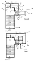
- the installation comprises a filter assembly 10, in particular a particulate filter, placed on an exhaust line 12 of an internal combustion engine, more particularly a diesel type engine.
- This assembly is traversed by the exhaust gas whose path is symbolized by the arrows 14 (gas inlet) and 16 (gas outlet) of Figure 1 and is divided into at least two filtration zones, here three zones 18 , 20, 22 preferably substantially equal.
- the installation also comprises a catalytic combustion device 26 which makes it possible to generate hot gases which are sent via a pipe 24 to this filtration assembly.
- This catalytic combustion device comprises an external air supply pump 28, and in the direction of circulation of this air along a pipe 30 connected to the connecting pipe 24, a device 32 for preheating the air circulating in the pipe 30, a fuel injection device 34 in the pipe and a catalytic element 36, hereinafter referred to as the catalyst description.
- the preheating device is preferably an electrical resistance placed in the pipe, between the pump and the fuel injection device 34, powered by a battery or supercapacitor, and swept by the air flowing through it. under the effect of the pump.
- the fuel injection device may be a pump injector connected to the fuel circuit that this engine usually comprises.
- the catalyst is of the oxidation catalyst type of the fuel contained in the fuel mixture which passes through it and makes it possible to heat the air contained in this mixture which passes through it very rapidly and thus to distribute hot gases to the pipe 24.
- This catalyst can be in the form of a monolith consisting of a corrugated metal strip wound on itself forming a cylindrical assembly called "honeycomb".
- This catalyst may also consist of a cordierite monolith or even a filter element, made of silicon carbide for example, impregnated with a catalytic oxidation formulation.
- the filter assembly 10 includes an exhaust gas manifold 38 connected to the exhaust line 12 and into which the exhaust gas is introduced.
- this manifold are placed several sensors and more precisely a pressure sensor 40 (upstream pressure sensor) and a temperature sensor 42 (upstream temperature sensor).
- This manifold opens via inputs 44, 46, 48 in the filtration zones 18, 20, 22 which each comprise, downstream of these inlets, a distribution compartment 50, 52, 54 provided upstream of a filter cartridge 56, 58, 60 and in which leads, by branches of the pipe 24, an inlet 62, 64, 66 of hot gases.
- the outputs of the cartridges result in an outlet manifold 68 connected to the exhaust line 12 and which also comprises several sensors, such as a pressure sensor 70 (downstream pressure sensor) and a temperature sensor 72 (downstream temperature sensor). .
- Each distribution compartment comprises a valve closing means 74, 76, 78 for controlling the exhaust gas inlet and / or the inlet 62, 64, 66 of hot gases.
- Valve or valve closing means are controlled by one or more actuators (not shown) independently of each other but never simultaneously closing all the inlets 44, 46, 48 of compartments 50, 52, 54.
- the valves each comprise two closure means connected to one another, a first means, called plate 80, able to open or close the arrival exhaust gas and a second means, said slide 82, for opening and closing the inlet of hot gases.
- the plate and the slide are arranged in such a way that the exhaust gas inlet and the hot gas inlet of the same compartment can not be closed simultaneously.
- the inlet and the inlet are arranged orthogonally with each other and, as a result, the plate and the slide are also orthogonally arranged.
- These closure means are controlled on the move by a rod 84 subjected to displacement in translation under the action of any known means, such as a jack, an electromagnet, etc.
- partitions 86 are provided to isolate the zones 18, 20, 22 between them and delimit the compartments 50, 52, 54 from each other.
- upstream and downstream mean, for the filtration assembly, the flow of the exhaust gas from the inlet manifold 38 to the outlet manifold 68 while in the case of the catalytic combustion device, the flow of air is considered pump 28 to the admissions 62, 64, 66.
- a control unit such as a motor-calculator which the engine usually comprises, determines the position of the valves 74, 76, 78 as a function of the various operating parameters of the engine.
- valves 74 and 76 are controlled by the control unit such that they open the entry of the exhaust gas 44 and 46 by closing the admissions 62 and 64 by the slides 82 while the valve 78 closes the inlet 48 This advantageously makes it possible to adapt the volume of filtration to the volume of the gases that passes through the filtration unit.
- the installation is in the state of loading, that is to say that the cartridges 56, 58 and 60 are not saturated by the particles. or soot contained in the exhaust gas.
- all the exhaust gas passes through the inlets 44 and 46, the manifold 38 to the compartments 50, 52, then through the cartridges 56 and 58 so that the particles contained in these gases are , in large part, retained by these cartridges and finally end up in the outlet manifold 68 to be rejected by the exhaust line 12.
- the resistor 32 is not supplied with fuel, no fuel is introduced into the pipe 30 by the injector 34 and the catalyst 36 is at ambient temperature.
- the control unit controls the valves so that only one exhaust gas inlet is open.
- the valve 76 will be actuated to close the inlet 46 of exhaust gas and only the inlet 44 will be open.
- the exhaust gas thus completely passes through this inlet 44 and then flows into the cartridge 56 and leaves the line 12 via the outlet manifold 68.
- a pressure drop is calculated by the control unit and then compared to a table of values contained in this unit. If the value of this pressure drop is lower than a threshold value of this table, the unit controls the valves so as to repeat this examination of the level of clogging on the next cartridge 58 by opening the inlet 46 and closing the door. In the same way, if the pressure drop of the cartridge 58 is lower than the threshold value, the operation will continue on the cartridge 60.
- the valve 74 closes the inlet 44 of exhaust gas by the plate 80 and releases the admission 62 of hot gases to proceed with the regeneration of this cartridge.
- the control unit will make it possible to better adapt the volume of the exhaust gases to be treated by the other cartridges by controlling the valves associated therewith so that at least one of the arrivals 46 and 48 be open.
- the unit controls the start of the pump 28 which circulates air in the pipe 30 and sends an electric current through the electrical resistance 32. In so doing, this resistance heats the air in this pipe so that it reaches a temperature of about 250 ° C, the boot temperature of the catalyst called start temperature or light off.
- This air temperature is constantly monitored by a temperature sensor 88 provided in the pipe 30 downstream of the catalyst 36. As soon as this temperature is reached, introduction of fuel into the pipe 30 and upstream of the catalyst 36 is achieved by the injector 34.
- the speed of regeneration of the cartridge will be controlled by the control unit which will control not only the amount of fuel introduced into the pipe 30 but also the flow of air circulating there through the pump 28. Similarly, this unit will interrupt if necessary the supply of the resistor 32.
- control unit actuates the valves so that the regeneration plant is in the configuration that preceded this regeneration and as shown in FIG. If it is necessary, the control unit will control the valves in a manner similar to that described above to regenerate another cartridge.
- it may be provided to mix an additive to the fuel before its injection into the pipe 30 by the injector 34 and this in order to lower the reaction temperature of the catalyst.
- this control unit controls the valve 74 to temporarily open the admission 44 by leaving the tray 80 of its seat while leaving the admission 62 open. This has the effect of introducing exhaust gas through this cartridge and thus avoid excessive heat exchange for this cartridge during its regeneration.
- the catalytic combustion device 26 comprises the same elements as those described in connection with Figure 1 (pump, heating resistor, fuel injector and catalyst).
- the catalyst 36 is placed as close as possible to the cartridges so that the path of the hot gases between this catalyst and the cartridges is minimized and thus to limit the thermal losses of these gases.
- this catalyst is bathed by the exhaust gas so that the latter transmit a portion of their heat energy to the catalyst and thus minimizes the power supply power of the resistor while reducing the time required for that the catalyst reaches its temperature of light off. More precisely, from the inlet manifold 38 part a pipe 90 whose mouth 92 originates at this manifold and whose outlet 94 of this pipe arrives in one of the compartments, here in the compartment 50 and upstream of the cartridge 56.
- This heating pipe 90 is traversed substantially orthogonally through the pipe 30 and has a transverse dimension such that the transverse dimension of the pipe 30 is included.
- the catalyst is placed in the region of the pipe 30 which crosses the heating pipe 90 so that the exhaust gases coming from the collector 38 surround by sweeping it the part of the pipe 30 in which the catalyst 36 is located and transmit their calories to this catalyst.
- the outlet 94 of the pipe 90 is not closed by the slide 82 of the valve 74 so that the exhaust flow continuously from the inlet manifold to the compartment by constantly bathing the section of the pipe carrying the catalyst.
- this catalyst so as to limit the thermal inertia of this catalyst, it can be expected to separate it into several elements, a first element instead of the catalyst 36 to ensure the catalytic combustion of the fuel mixture circulating in the pipe 30 and a second catalytic element 36b placed upstream of the cartridge 56 and downstream of the hot gas inlet 62 and whose role will be to oxidize the unburned hydrocarbons (HC) and the carbon oxides (CO) present in the gases of exhaust and / or in hot gases resulting from catalytic combustion.
- HC unburned hydrocarbons
- CO carbon oxides
- the operation of the filtration assembly comprising the elements described in relation with FIG. 6 will be identical to that described with reference to FIGS. 1 to 5 with the additional advantage that the catalyst 36 will be at a temperature substantially close to that of the gases exhaust. This makes it possible to make the catalyst 36 operational more quickly thanks to the heating pipe 90 and to limit the electrical power to be sent to the resistor to heat the air flowing in the pipe 30.
- the pipe 130 carrying the resistor 32, the injector 34 and the catalyst 36 starts at the inlet manifold 38 and results in the admission of hot gases 62 as previously described in relation with FIGS. .
- the resistor 32 is energized (in the case where the temperature of the exhaust gas is not sufficient to bring the catalyst 36 to its start-up or light-off temperature) and heats the exhaust gases flowing through it.
- the fuel injector introduces fuel into the pipe 130, downstream of the resistance and upstream of the catalyst, and interrupts the power supply of the resistor, if necessary.
- the exhaust gas flowing in this pipe contains enough oxygen for the fuel mixture passing through the catalyst 36 to be oxidized and provides catalyst output of hot gases which will then be introduced through the inlet 62 into the compartment 50 and then pass through the cartridge 56.
- either the catalyst 36 or the cartridges 56, 58, 60 are impregnated with a catalytic formulation for reducing the NOx present in the hot gases or in the exhaust gas.
Abstract
Description
La présente invention se rapporte à un procédé de régénération de filtre à particules, notamment de particules présentes dans les gaz d'échappement de moteur à combustion interne, et à une installation utilisant un tel procédé.The present invention relates to a particle filter regeneration method, in particular particles present in the exhaust gas of an internal combustion engine, and to an installation using such a method.
Elle vise notamment le domaine de la gestion de l'encrassement d'un filtre placé dans la ligne d'échappement d'un moteur à combustion interne, notamment de type Diesel, et traversé par des gaz d'échappement transportant des particules, telles que des particules carbonées ou des suies.It aims in particular the field of the management of the fouling of a filter placed in the exhaust line of an internal combustion engine, in particular of diesel type, and traversed by exhaust gases carrying particles, such as carbonaceous particles or soot.
De tels moteurs génèrent des quantités de particules particulièrement élevées et leurs lignes d'échappement sont de plus en plus souvent équipées de filtres qui retiennent ces particules avec des efficacités de filtration très importantes, voisine de 100%.Such engines generate particularly high amounts of particles and their exhaust lines are increasingly equipped with filters that retain these particles with very high filtration efficiencies, close to 100%.
Cependant de tels filtres doivent être périodiquement régénérés afin d'éviter leur colmatage par encrassement. En effet, le colmatage entraîne une augmentation de la contre-pression à l'échappement, ce qui a pour effet d'accroître la consommation en carburant du moteur. Dans le cas extrême d'un colmatage total de ce filtre, cela peut entraîner un grave dysfonctionnement du moteur, voire un arrêt complet du fonctionnement de ce moteur, et/ou la destruction du filtre.However, such filters must be periodically regenerated to prevent clogging by fouling. Indeed, the clogging causes an increase in the exhaust back pressure, which has the effect of increasing the fuel consumption of the engine. In the extreme case of a total clogging of this filter, this can cause a serious malfunction of the engine, or even a complete stop of the operation of this engine, and / or the destruction of the filter.
La régénération d'un filtre à particules se produit parfois naturellement, lorsque la température des gaz d'échappement a atteint le niveau nécessaire pour brûler les particules présentes sur ce filtre.The regeneration of a particulate filter sometimes occurs naturally, when the temperature of the exhaust gas has reached the level necessary to burn the particles present on this filter.
Toutefois, dans certaines conditions de fonctionnement du moteur, la température des gaz d'échappement n'est pas suffisante pour assurer la régénération du filtre et il est alors nécessaire de déclencher artificiellement la combustion des particules lorsque l'encrassement du filtre a atteint un certain seuil.However, under certain operating conditions of the engine, the temperature of the exhaust gas is not sufficient to ensure the regeneration of the filter and it is then necessary to artificially trigger the combustion of the particles when the fouling of the filter has reached a certain threshold.
Cela peut consister à augmenter la température du filtre au-dessus de 550° C, généralement en augmentant temporairement la richesse des gaz d'échappement qui le traversent sans qu'elle n'atteigne la richesse 1, et à obtenir une composition oxydante de ces mêmes gaz pour réaliser la combustion des particules retenues dans ce filtre.This may be to increase the temperature of the filter above 550 ° C, generally temporarily increasing the richness of the exhaust gas passing through it without it reaching the richness 1, and to obtain an oxidizing composition of these same gases to achieve the combustion of particles retained in this filter.
Ceci a pour inconvénient majeur d'augmenter la consommation de carburant.This has the major disadvantage of increasing fuel consumption.
Une autre technique consiste, comme mieux décrit dans le brevet européen EP 0 341 832, à disposer un catalyseur d'oxydation du monoxyde d'azote (NO) en amont du filtre. Ce catalyseur oxyde le monoxyde d'azote contenu dans les gaz d'échappement en dioxyde d'azote (NO2) et ce dioxyde d'azote est ensuite utilisé pour permettre la combustion des particules piégées sur le filtre à une température comprise entre 280° C et 400° C.Another technique consists, as better described in European Patent EP 0 341 832, in arranging a catalyst for the oxidation of nitrogen monoxide (NO) upstream of the filter. This catalyst oxidizes the nitric oxide contained in the exhaust gases to nitrogen dioxide (NO 2 ) and this nitrogen dioxide is then used to allow the combustion of particles trapped on the filter at a temperature of between 280 ° C. C and 400 ° C.
Cette technique nécessite d'utiliser un carburant Diesel en teneur en soufre très bas (de l'ordre de 50 ppm) pour pouvoir maintenir une efficacité de conversion suffisante du catalyseur d'oxydation visant à obtenir une grande quantité de NO transformée en NO2.This technique requires the use of a diesel fuel with a very low sulfur content (of the order of 50 ppm) in order to maintain a sufficient conversion efficiency of the oxidation catalyst to obtain a large amount of NO transformed into NO 2 .
D'autres techniques font appel à un procédé chimique pour lequel des additifs organométalliques, tel que le cérium par exemple, sont ajoutés au carburant Diesel de manière à obtenir une combustion des particules présentes sur le filtre à une température voisine de 400° C à 450° C.Other techniques use a chemical process for which organometallic additives, such as cerium for example, are added to the diesel fuel so as to obtain a combustion of the particles present on the filter at a temperature in the region of 400 ° C. to 450 ° C. ° C.
L'utilisation de tels additifs est d'un coût non négligeable et nécessite un dispositif particulier d'introduction de ces additifs, notamment dans le réservoir de carburant Diesel.The use of such additives is a significant cost and requires a particular device for introducing these additives, especially in the diesel fuel tank.
Il est également connu de chauffer ces gaz d'échappement par des dispositifs rapportés placés dans la ligne d'échappement et en amont du filtre comme des brûleurs ou comme des résistances électriques telles que mieux décrites dans les brevets FR 2 753 393 et FR 2 755 623 du demandeur.It is also known to heat these exhaust gases by attached devices placed in the exhaust line and upstream of the filter such as burners or as electrical resistors such as better described in patents FR 2 753 393 and FR 2 755 623 of the applicant.
Dans cette configuration, il est nécessaire d'apporter une grande quantité d'énergie calorifique aux gaz d'échappement soit en brûlant une quantité importante de carburant, dans le cas d'une utilisation de brûleur, soit en utilisant une forte puissance électrique pour les résistances électriques.In this configuration, it is necessary to provide a large amount of heat energy to the exhaust gas either by burning a large amount of fuel, in the case of a burner use, or by using a high electrical power for them. electrical resistances.
Ceci a pour inconvénient majeur d'augmenter, de façon non négligeable, la consommation en carburant du moteur et de nuire au confort de conduite.This has the major disadvantage of significantly increase the fuel consumption of the engine and impair driving comfort.
La présente invention se propose de remédier aux inconvénients mentionnés ci-dessus grâce à un procédé et à un dispositif qui permette d'atteindre des températures de régénération très rapidement et en minimisant la consommation.The present invention proposes to overcome the drawbacks mentioned above by means of a method and a device which makes it possible to reach regeneration temperatures very rapidly and by minimizing consumption.
A cet effet, la présente invention concerne un procédé de régénération d'un filtre à particules placé dans la ligne d'échappement d'un moteur à combustion interne, notamment de type Diesel, procédé dans lequel on évalue l'état de colmatage du filtre, on compare cet état à une valeur-seuil puis, en cas de dépassement de cette valeur-seuil, on réalise un mélange d'un fluide et d'un carburant, on réalise une combustion catalytique de ce mélange pour générer les gaz chauds nécessaires à la régénération du filtre et on procède à la régénération du filtre par des gaz chauds traversant ledit filtre et ayant une température suffisante pour assurer la combustion des particules retenues dans ce filtre, caractérisé en ce que, au préalable de la réalisation du mélange du fluide et du carburant, on élève la température du fluide jusqu'à la température de démarrage de la combustion catalytique.For this purpose, the present invention relates to a method of regenerating a particulate filter placed in the exhaust line of an internal combustion engine, in particular of the Diesel type, in which method the filter clogging state is evaluated. this state is compared with a threshold value and then, if this threshold value is exceeded, a mixture of a fluid and a fuel is produced, a catalytic combustion of this mixture is carried out in order to generate the necessary hot gases. at the regeneration of the filter and the filter is regenerated by hot gases passing through said filter and having a temperature sufficient to ensure the combustion of the particles retained in this filter, characterized in that, prior to the production of the fluid mixture and fuel, the temperature of the fluid is raised to the starting temperature of the catalytic combustion.
De manière avantageuse, on peut réaliser l'élévation de température du fluide en chauffant ledit fluide par une résistance chauffante.Advantageously, the temperature rise of the fluid can be achieved by heating said fluid with a heating resistor.
On peut utiliser, comme fluide, de l'air et/ou les gaz d'échappement du moteur.As fluid, air and / or engine exhaust gases may be used.
On peut faire circuler les gaz d'échappement autour d'un élément catalytique utilisé pour la combustion catalytique afin d'élever la température dudit élément.The exhaust gas can be circulated around a catalytic element used for catalytic combustion to raise the temperature of said element.
On peut ajouter un additif au carburant pour abaisser la température de combustion des particules.An additive to the fuel can be added to lower the combustion temperature of the particles.
L'invention concerne également une installation de filtration de gaz d'échappement d'un moteur à combustion interne, notamment de type Diesel, avec un ensemble de filtration comprenant au moins une zone de filtration comportant une cartouche de filtration traversée par les gaz d'échappement du moteur, et un dispositif à combustion catalytique permettant de générer des gaz chauds nécessaires à la régénération d'au moins une desdites cartouches, caractérisée en ce qu'elle comprend un élément de préchauffage du fluide traversant le dispositif à combustion catalytique.The invention also relates to an exhaust gas filtration installation of an internal combustion engine, in particular of Diesel type, with a filtration assembly comprising at least one filtration zone comprising a filtration cartridge through which the exhaust gas passes through. engine exhaust, and a catalytic combustion device for generating hot gases necessary for the regeneration of at least one of said cartridges, characterized in that it comprises a fluid preheating element passing through the catalytic combustion device.
Le dispositif à combustion catalytique peut comprendre une conduite raccordée à l'ensemble de filtration et portant un élément catalytique et un dispositif d'injection de carburant.The catalytic combustion device may comprise a pipe connected to the filter assembly and carrying a catalytic element and a fuel injection device.
De manière préférentielle, l'élément de préchauffage peut comprendre une résistance électrique.Preferably, the preheating element may comprise an electrical resistance.
Le dispositif à combustion catalytique peut comprendre un moyen de pompage du fluide prévu pour traverser l'élément catalytique.The catalytic combustion device may comprise a fluid pumping means provided for passing through the catalytic element.
L'installation de filtration peut comprendre un compartiment de répartition placé en amont de la cartouche et portant une arrivée de gaz d'échappement du moteur et une admission de gaz chauds provenant du dispositif à combustion catalytique.The filtration installation may comprise a distribution compartment placed upstream of the cartridge and carrying an engine exhaust gas inlet and a hot gas inlet from the catalytic combustion device.
Le compartiment de répartition peut comprendre un moyen d'obturation par vanne pour contrôler l'arrivée des gaz d'échappement du moteur et l'admission des gaz chauds.The distribution compartment may include valve closure means to control the flow of engine exhaust and the admission of hot gases.
L'installation de filtration peut comprendre une conduite de chauffage de l'élément catalytique.The filtration installation may comprise a heating pipe for the catalytic element.
L'élément catalytique peut comprendre un élément catalyseur pour la combustion catalytique et un élément catalytique d'oxydation des gaz d'échappement.The catalytic element may comprise a catalyst element for catalytic combustion and a catalytic exhaust oxidation catalyst element.
L'élément catalytique peut être imprégné d'une formulation catalytique permettant de réduire les oxydes d'azote des gaz d'échappement.The catalytic element may be impregnated with a catalytic formulation to reduce the nitrogen oxides of the exhaust gas.
Les autres caractéristiques et avantages de l'invention vont apparaître à la lecture de la description qui va suivre, donnée à titre uniquement illustratif et non limitatif, et à laquelle sont annexées :
- la figure 1 qui est un schéma montrant l'installation de régénération de filtre à particules selon l'invention ;
- la figure 2 qui illustre un exemple de réalisation de l'ensemble de filtration de l'installation de la figure 1 ;
- la figure 3 qui est une vue en coupe latérale selon la ligne 3-3 de la figure 2;
- la figure 4 qui est une vue semblable à la figure 3 et montrant en mode régénération ;
- la figure 5 qui illustre une variante de l'élément de l'installation de la figure 4 ;
- la figure 6 qui montre une vue en coupe latérale d'une variante de l'exemple de réalisation de la figure 2 et
- la figure 7 qui présente une vue en coupe latérale d'une autre variante de l'exemple de réalisation de la figure 2.
- Figure 1 which is a diagram showing the particle filter regeneration installation according to the invention;
- Figure 2 which illustrates an embodiment of the filter assembly of the installation of Figure 1;
- Figure 3 which is a side sectional view along the line 3-3 of Figure 2;
- Figure 4 which is a view similar to Figure 3 and showing in regeneration mode;
- Figure 5 which illustrates a variant of the element of the installation of Figure 4;
- FIG. 6 shows a side sectional view of a variant of the embodiment of FIG. 2 and
- FIG. 7 which shows a side sectional view of another variant of the embodiment of FIG. 2.
Sur la figure 1, l'installation comprend un ensemble de filtration 10, notamment un filtre à particules, placé sur une ligne d'échappement 12 d'un moteur à combustion interne, plus particulièrement d'un moteur de type Diesel.In Figure 1, the installation comprises a
Cet ensemble est traversé par les gaz d'échappement dont le trajet est symbolisé par les flèches 14 (entrée de gaz) et 16 (sortie de gaz) de la figure 1 et est divisé en au moins deux zones de filtration, ici trois zones 18, 20, 22 de préférence sensiblement égales. L'installation comprend également un dispositif à combustion catalytique 26 qui permet de générer des gaz chauds qui sont envoyés par une conduite 24 à cet ensemble de filtration.This assembly is traversed by the exhaust gas whose path is symbolized by the arrows 14 (gas inlet) and 16 (gas outlet) of Figure 1 and is divided into at least two filtration zones, here three
Ce dispositif à combustion catalytique, comprend une pompe d'alimentation en air extérieur 28, et dans le sens de circulation de cet air le long d'une conduite 30 raccordée à la conduite de raccordement 24, un dispositif de préchauffage 32 de l'air circulant dans la conduite 30, un dispositif d'injection de carburant 34 dans la conduite et un élément catalytique 36, dénommé dans la suite de la description catalyseur.This catalytic combustion device comprises an external
Le dispositif de préchauffage est préférentiellement une résistance électrique placée au sein de la conduite, entre la pompe et le dispositif d'injection de carburant 34, alimentée en courant électrique par une batterie ou par une supercapacité, et balayée par l'air qui y circule sous l'effet de la pompe. Le dispositif d'injection de carburant peut être un injecteur-pompe connecté au circuit de carburant que comprend habituellement ce moteur. Le catalyseur est du type catalyseur d'oxydation du carburant contenu dans le mélange carburé qui le traverse et permet de chauffer très rapidement l'air contenu dans ce mélange qui le traverse et de distribuer ainsi des gaz chauds à la conduite 24. Ce catalyseur peut être sous la forme d'un monolithe constitué d'un feuillard métallique ondulé enroulé sur lui-même en formant un ensemble cylindrique appelé "nid d'abeille". La taille de cet ensemble cylindrique est fonction du volume des gaz d'échappement qui le traverse et cela afin de limiter la contre-pression. Ce catalyseur peut également être constitué d'un monolithe en cordiérite voire d'un élément filtrant, en carbure de silicium par exemple, imprégné d'une formulation catalytique d'oxydation.The preheating device is preferably an electrical resistance placed in the pipe, between the pump and the
En se rapportant à la figure 2, l'ensemble de filtration 10 comprend un collecteur d'arrivée de gaz d'échappement 38 raccordé à la ligne d'échappement 12 et dans lequel sont introduits les gaz d'échappement. Dans ce collecteur sont placés plusieurs capteurs et plus précisément un capteur de pression 40 (capteur de pression amont) et un capteur de température 42 (capteur de température amont). Ce collecteur débouche par des entrées 44, 46, 48 dans les zones de filtration 18, 20, 22 qui comprennent chacune, en aval de ces entrées, un compartiment de répartition 50, 52, 54 prévu en amont d'une cartouche filtrante 56, 58, 60 et dans lequel aboutit, par des dérivations de la conduite 24, une admission 62, 64, 66 de gaz chauds. Les sorties des cartouches aboutissent à un collecteur de sortie 68 raccordé à la ligne d'échappement 12 et qui comprend également plusieurs capteurs, comme un capteur de pression 70 (capteur de pression aval) et un capteur de température 72 (capteur de température aval).Referring to Figure 2, the
Chaque compartiment de répartition comprend un moyen de d'obturation par vanne 74, 76, 78 permettant de contrôler l'entrée de gaz d'échappement et/ou l'admission 62, 64, 66 de gaz chauds.Each distribution compartment comprises a valve closing means 74, 76, 78 for controlling the exhaust gas inlet and / or the
Les moyens d'obturation par vanne ou vannes sont commandés par un ou plusieurs actionneurs (non représentés) et ce de façon indépendante les uns des autres mais en n'obturant jamais de manière simultanée toutes les entrées 44, 46, 48 des compartiments 50, 52, 54.Valve or valve closing means are controlled by one or more actuators (not shown) independently of each other but never simultaneously closing all the
A titre d'exemple et comme mieux illustré sur les figures 3 à 7, les vannes comprennent chacune deux moyens d'obturation liés l'un à l'autre, un premier moyen, dit plateau 80, apte à ouvrir ou fermer l'arrivée de gaz d'échappement et un deuxième moyen, dit coulisse 82, permettant d'ouvrir et de fermer l'admission de gaz chauds. Le plateau et la coulisse sont disposés d'une manière telle que l'arrivée de gaz d'échappement et l'admission de gaz chauds d'un même compartiment ne peuvent pas être fermées simultanément. De préférence, l'arrivée et l'admission sont disposées orthogonalement l'une avec l'autre et de ce fait, le plateau et la coulisse sont également disposés orthogonalement. Ces moyens d'obturation sont commandés en déplacement par une tige 84 soumise à un déplacement en translation sous l'action de tout moyen connu, comme un vérin, un électroaimant,...By way of example and as best illustrated in FIGS. 3 to 7, the valves each comprise two closure means connected to one another, a first means, called
En outre, des cloisons 86 sont prévues pour isoler les zones 18, 20, 22 entre elles et délimiter les compartiments 50, 52, 54 les uns des autres.In addition,
Dans le cas de la présente description, les termes « amont » et « aval » s'entendent, pour l'ensemble de filtration, comme la circulation des gaz d'échappement du collecteur d'arrivée 38 vers le collecteur de sortie 68 alors que, dans le cas du dispositif à combustion catalytique, la circulation de l'air est considérée de la pompe 28 vers les admissions 62, 64, 66.In the case of the present description, the terms "upstream" and "downstream" mean, for the filtration assembly, the flow of the exhaust gas from the
En fonctionnement, une unité de contrôle (non représentée), tel qu'un calculateur-moteur que comporte habituellement le moteur, détermine la position des vannes 74, 76, 78 en fonction des différents paramètres de fonctionnement du moteur.In operation, a control unit (not shown), such as a motor-calculator which the engine usually comprises, determines the position of the
Comme illustré à la figure 2 à titre d'exemple, il peut être prévu que, pour des charges moyennes du moteur ou pour des débits moyens de gaz d'échappement (de l'ordre de 200 à 400m3/h), les vannes 74 et 76 soient commandées par l'unité de contrôle de telle manière qu'elles ouvrent l'entrée des gaz d'échappement 44 et 46 en fermant les admissions 62 et 64 par les coulisses 82 alors que la vanne 78 obture l'entrée 48 de gaz d'échappement par le plateau 80. Ceci permet avantageusement d'adapter le volume de filtration au volume des gaz qui traverse l'ensemble de filtration.As illustrated in Figure 2 by way of example, it can be expected that for average engine loads or for average exhaust gas flow rates (of the order of 200 to 400m 3 / h), the
A titre d'exemple, il est considéré que l'installation, comme montré aux figures 2 et 3, est en état de chargement, c'est-à-dire que les cartouches 56, 58 et 60 ne sont pas saturées par les particules ou suies contenues dans les gaz d'échappement. Dans ce cas, la totalité des gaz d'échappement passe, au travers des entrées 44 et 46, du collecteur 38 vers les compartiments 50, 52, puis traversent les cartouches 56 et 58 de manière à ce que les particules contenues dans ces gaz soient, en très grande partie, retenues par ces cartouches et enfin aboutissent dans le collecteur de sortie 68 pour être rejetés par la ligne d'échappement 12. Dans cette configuration, la résistance 32 n'est pas alimenté en carburant, aucun carburant n'est introduit dans la conduite 30 par l'injecteur 34 et le catalyseur 36 est à température ambiante.By way of example, it is considered that the installation, as shown in FIGS. 2 and 3, is in the state of loading, that is to say that the
Périodiquement, généralement tous les 200 km ou toutes les deux heures de fonctionnement, période qui peut être modifiée en fonction des conditions d'utilisation, il est réalisé une estimation du niveau de colmatage de l'ensemble de filtration. Plus particulièrement, il va être examiné l'état de colmatage par les particules de chaque cartouche 56, 58, 60.Periodically, generally every 200 km or every two hours of operation, a period that can be modified according to the conditions of use, an estimate is made of the level of clogging of the filtration assembly. More particularly, the state of clogging by the particles of each
Pour ce faire et en partant de la configuration de la figure 2, l'unité de contrôle commande les vannes de façon à ce qu'une seule entrée de gaz d'échappement soit ouverte. Ainsi à partir de l'exemple montré à la figure 2, la vanne 76 sera actionnée pour obturer l'entrée 46 de gaz d'échappement et seule l'entrée 44 sera ouverte. Les gaz d'échappement traversent donc, dans leur totalité, cette entrée 44 puis circulent dans la cartouche 56 et ressortent dans la ligne 12 par le collecteur de sortie 68. Grâce aux capteur de pression amont 40 et aval 70, une perte de charge est calculée par l'unité de contrôle puis comparée à une table de valeurs contenue dans cette unité. Si la valeur de cette perte de charge est inférieure à une valeur-seuil de cette table, l'unité commande les vannes de façon à répéter cet examen du niveau de colmatage sur la cartouche suivante 58 en ouvrant l'entrée 46 et en fermant l'entrée 44. De même, si la perte de charge de la cartouche 58 est inférieure à la valeur-seuil, l'opération se poursuivra sur la cartouche 60.To do this and starting from the configuration of Figure 2, the control unit controls the valves so that only one exhaust gas inlet is open. Thus from the example shown in Figure 2, the
Si la valeur-seuil de la perte de charge de l'une des cartouches est atteinte, par exemple la cartouche 56 comme illustré sur la figure 4, alors la vanne 74 ferme l'entrée 44 de gaz d'échappement par le plateau 80 et libère l'admission 62 de gaz chauds pour procéder à la régénération de cette cartouche. Bien entendu, l'unité de contrôle fera en sorte d'adapter au mieux le volume des gaz d'échappement à traiter par les autres cartouches en commandant les vannes qui y sont associées de façon à ce qu'au moins une des arrivées 46 et 48 soient ouvertes.If the threshold value of the pressure drop of one of the cartridges is reached, for example the
Simultanément à la fermeture de l'arrivée 44, l'unité commande la mise en marche de la pompe 28 qui fait circuler de l'air dans la conduite 30 et envoie un courant électrique au travers de la résistance électrique 32. Ce faisant, cette résistance chauffe l'air dans cette conduite pour qu'il atteigne une température voisine de 250°C, température d'amorçage du catalyseur dite température de démarrage ou de light off. Cette température de l'air est constamment surveillée par un capteur de température 88 prévu dans la conduite 30 en aval du catalyseur 36. Dès que cette température est atteinte, une introduction de carburant dans la conduite 30 et en amont du catalyseur 36 est réalisée par l'injecteur 34. Par réaction catalytique, le mélange air/carburant traversant ce catalyseur se consume et les gaz chauds sortant de ce catalyseur atteignent une température supérieure à 550°C, température nécessaire et suffisante pour assurer la combustion des particules présentes dans la cartouche à régénérer. Ces gaz chauds pénètrent ensuite dans le compartiment 50 par l'admission 62, traversent la cartouche 56 pour y brûler les particules retenues dans celle-ci et ressortent par le collecteur 68 pour être évacués dans la ligne d'échappement 12.Simultaneously with the closure of the
La vitesse de régénération de la cartouche sera contrôlée par l'unité de contrôle qui pilotera non seulement la quantité de carburant introduite dans la conduite 30 mais aussi le débit d'air qui y circule grâce à la pompe 28. De même, cette unité interrompra si nécessaire l'alimentation de la résistance 32.The speed of regeneration of the cartridge will be controlled by the control unit which will control not only the amount of fuel introduced into the
Une fois que la régénération de la cartouche 56 est terminée, l'unité de contrôle actionne les vannes de façon à ce que l'installation de régénération se retrouve dans la configuration ayant précédé cette régénération et comme illustré à la figure 2. Si cela s'avère nécessaire, l'unité de contrôle commandera les vannes d'une manière semblable à celle décrite ci-dessus pour procéder à la régénération d'une autre cartouche.Once the regeneration of the
Avantageusement, il peut être prévu de mélanger un additif au carburant avant son injection dans la conduite 30 par l'injecteur 34 et ce afin de baisser la température de réaction du catalyseur.Advantageously, it may be provided to mix an additive to the fuel before its injection into the
Préférentiellement et comme visible sur la figure 5, pendant la régénération de la cartouche 56 et en fonction des températures amont et aval relevés par les capteurs 42 et 72 et communiquées à l'unité de contrôle, il peut être prévu que cette unité de contrôle commande la vanne 74 pour ouvrir temporairement l'admission 44 en faisant quitter le plateau 80 de son siège tout en laissant l'admission 62 ouverte. Ceci a pour effet d'introduire des gaz d'échappement au travers de cette cartouche et d'éviter ainsi un échange de chaleur trop important pour cette cartouche lors de sa régénération.Preferably and as visible in FIG. 5, during the regeneration of the
L'exemple montré à la figure 6 est une variante de la figure 2 et pour cela comporte les mêmes références pour les parties communes aux deux figures.The example shown in Figure 6 is a variant of Figure 2 and for this includes the same references for the common parts of the two figures.
Dans cette variante, le dispositif à combustion catalytique 26 comporte les mêmes éléments que ceux décrits en relation avec la figure 1 (pompe, résistance chauffante, injecteur de carburant et catalyseur). Dans cet exemple le catalyseur 36 est placé au plus près des cartouches de manière à ce que le cheminement des gaz chauds entre ce catalyseur et les cartouches soit minimisé et ainsi à limiter les pertes thermiques de ces gaz.In this variant, the
Avantageusement, il peut être prévu que ce catalyseur soit baigné par les gaz d'échappement afin que ces derniers transmettent une partie de leur énergie calorifique à ce catalyseur et ainsi minimise la puissance électrique d'alimentation de la résistance tout en diminuant le temps nécessaire pour que le catalyseur atteigne sa température de light off. Plus précisément, à partir du collecteur d'arrivée 38 part une conduite 90 dont l'embouchure 92 prend naissance à ce collecteur et dont le débouché 94 de cette conduite arrive dans un des compartiments, ici dans le compartiment 50 et en amont de la cartouche 56. Cette conduite de chauffage 90 est traversée sensiblement orthogonalement par la conduite 30 et a une dimension transversale telle que la dimension transversale de la conduite 30 y soit comprise. Le catalyseur est placé dans la région de la conduite 30 qui croise la conduite de chauffage 90 de manière à ce que les gaz d'échappement venant du collecteur 38 entourent en la balayant la partie de la conduite 30 dans laquelle se trouve le catalyseur 36 et transmettent leurs calories à ce catalyseur.Advantageously, it may be provided that this catalyst is bathed by the exhaust gas so that the latter transmit a portion of their heat energy to the catalyst and thus minimizes the power supply power of the resistor while reducing the time required for that the catalyst reaches its temperature of light off. More precisely, from the
Préférentiellement, le débouché 94 de la conduite 90 n'est pas obturé par la coulisse 82 de la vanne 74 de façon à ce que les gaz d'échappement circulent en permanence du collecteur d'arrivée vers le compartiment en baignant constamment la section de la conduite qui porte le catalyseur.Preferably, the
Avantageusement, de façon à limiter l'inertie thermique de ce catalyseur, il peut être prévu de le séparer en plusieurs éléments, un premier élément en lieu et place du catalyseur 36 pour assurer la combustion catalytique du mélange carburé circulant dans la conduite 30 et un deuxième élément catalytique 36b placé en amont de la cartouche 56 et en aval de l'admission de gaz chauds 62 et dont le rôle sera d'oxyder les hydrocarbures imbrûlés (HC) et les oxydes de carbones (CO) présent dans les gaz d'échappement et/ou dans les gaz chauds résultant de la combustion catalytique.Advantageously, so as to limit the thermal inertia of this catalyst, it can be expected to separate it into several elements, a first element instead of the
Le fonctionnement de l'ensemble de filtration comportant les éléments décrits en relation avec la figure 6 sera identique à celui décrit en relation avec les figures 1 à 5 avec l'avantage supplémentaire que le catalyseur 36 sera à une température sensiblement voisine de celle des gaz d'échappement. Ceci permet de rendre opérationnel plus rapidement le catalyseur 36 grâce à la conduite de chauffage 90 et de limiter la puissance électrique à envoyer à la résistance pour chauffer l'air circulant dans la conduite 30.The operation of the filtration assembly comprising the elements described in relation with FIG. 6 will be identical to that described with reference to FIGS. 1 to 5 with the additional advantage that the
La réalisation illustrée à la figure 7 est une variante de la figure 6 et pour cela comporte les mêmes références que cette figure.The embodiment illustrated in Figure 7 is a variant of Figure 6 and for this includes the same references as this figure.
Cette variante se distingue de la figure 6 dans le sens que le dispositif à combustion catalytique est dépourvu de pompe de circulation de l'air.This variant differs from Figure 6 in the sense that the catalytic combustion device is devoid of air circulation pump.
Dans ce cas, la conduite 130 portant la résistance 32, l'injecteur 34 et le catalyseur 36 débute au niveau du collecteur d'arrivée 38 et aboutit à l'admission de gaz chauds 62 comme précédemment décrite en relation avec les figures 1 à 5.In this case, the
Ainsi, pendant le fonctionnement des opérations de régénération des cartouches, la résistance 32 est alimentée (dans le cas où la température des gaz d'échappement n'est pas suffisante pour porter le catalyseur 36 à sa température de démarrage ou de light off) et chauffe les gaz d'échappement qui la parcourent. Dès que cette température est atteinte grâce à la mesure effectuée par le capteur 88, l'injecteur de carburant introduit du carburant dans la conduite 130, en aval de la résistance et en amont du catalyseur, et interrompt l'alimentation de la résistance, si nécessaire. Les gaz d'échappement circulant dans cette conduite contiennent suffisamment d'oxygène pour que le mélange carburé qui traverse le catalyseur 36 soit oxydé et procure en sortie de catalyseur des gaz chauds qui seront ensuite introduits par l'admission 62 dans le compartiment 50 puis traverseront la cartouche 56.Thus, during the operation of the cartridge regeneration operations, the
Bien entendu, la présente invention n'est pas limitée aux exemples de réalisation décrits mais englobe tout équivalent et variante.Of course, the present invention is not limited to the embodiments described but encompasses any equivalent and variant.
Notamment, il peut être envisagé que soit le catalyseur 36 soit les cartouches 56, 58, 60 soient imprégnés d'une formulation catalytique permettant de réduire les NOx présents dans les gaz chauds ou dans les gaz d'échappement.In particular, it can be envisaged that either the
Claims (15)
Applications Claiming Priority (1)
| Application Number | Priority Date | Filing Date | Title |
|---|---|---|---|
| FR0413622A FR2879654B1 (en) | 2004-12-20 | 2004-12-20 | METHOD FOR REGENERATING PARTICLE FILTER WITH CATALYTIC COMBUSTION DEVICE AND FILTRATION FACILITY USING SUCH A METHOD |
Publications (2)
| Publication Number | Publication Date |
|---|---|
| EP1672194A1 true EP1672194A1 (en) | 2006-06-21 |
| EP1672194B1 EP1672194B1 (en) | 2010-03-10 |
Family
ID=34953594
Family Applications (1)
| Application Number | Title | Priority Date | Filing Date |
|---|---|---|---|
| EP05292666A Not-in-force EP1672194B1 (en) | 2004-12-20 | 2005-12-09 | Method of regeneration of a particulate filter with an catalytic combustion apparatus and filter installation using the method |
Country Status (5)
| Country | Link |
|---|---|
| US (1) | US7650748B2 (en) |
| EP (1) | EP1672194B1 (en) |
| AT (1) | ATE460575T1 (en) |
| DE (1) | DE602005019837D1 (en) |
| FR (1) | FR2879654B1 (en) |
Cited By (1)
| Publication number | Priority date | Publication date | Assignee | Title |
|---|---|---|---|---|
| WO2021047853A1 (en) * | 2019-09-13 | 2021-03-18 | Daimler Ag | Exhaust-gas system for an internal combustion engine of a motor vehicle, drive device for a motor vehicle, and motor vehicle |
Families Citing this family (4)
| Publication number | Priority date | Publication date | Assignee | Title |
|---|---|---|---|---|
| WO2013032486A1 (en) * | 2011-09-02 | 2013-03-07 | International Engine Intellectual Property Company, Llc | Catalytic burner system for dpf regeneration |
| US9010098B2 (en) * | 2012-10-24 | 2015-04-21 | Electro-Motive Diesel, Inc. | After-treatment device |
| GB2511772B (en) | 2013-03-12 | 2019-01-30 | Ceramex Ltd | Testing catalytic efficiency of an exhaust component |
| KR102144271B1 (en) * | 2020-06-19 | 2020-08-13 | 주식회사 스마트파워 | Smoke reduction device for generator engine with non-rupturable disc valve that can be used repeatedly |
Citations (15)
| Publication number | Priority date | Publication date | Assignee | Title |
|---|---|---|---|---|
| JPS59101522A (en) * | 1982-12-02 | 1984-06-12 | Yanmar Diesel Engine Co Ltd | Exhaust gas treating device for diesel engine |
| US4459805A (en) * | 1980-10-03 | 1984-07-17 | Nippon Soken, Inc. | Combustion burner apparatus |
| US4485621A (en) * | 1983-01-07 | 1984-12-04 | Cummins Engine Company, Inc. | System and method for reducing particulate emissions from internal combustion engines |
| EP0341832A2 (en) | 1988-05-13 | 1989-11-15 | Johnson Matthey Inc. | Treatment of diesel exhaust gas |
| FR2753393A1 (en) | 1996-09-13 | 1998-03-20 | Inst Francais Du Petrole | METHOD AND DEVICE FOR CONTROLLING A PARTICLE FILTER |
| FR2755623A1 (en) | 1996-11-12 | 1998-05-15 | Inst Francais Du Petrole | METHOD AND EXHAUST GAS FILTRATION UNIT HAVING MODULAR HEATING |
| US5826428A (en) * | 1995-02-09 | 1998-10-27 | J. Eberspacher Gmbh & Co. | Burner for the thermal regeneration of a particle filter in an exhaust gas aftertreatment system of an internal combustion engine, especially a diesel engine |
| US6233926B1 (en) * | 2000-03-01 | 2001-05-22 | Illinois Valley Holding Company | Apparatus and method for filtering particulate in an exhaust trap |
| EP1149232A1 (en) * | 1998-11-06 | 2001-10-31 | Ceryx Incorporated | Integrated apparatus for removing pollutants from a fluid stream in a lean-burn environment with heat recovery |
| US20020178922A1 (en) * | 1998-09-30 | 2002-12-05 | Ibiden Co., Ltd | Regeneration system for an exhaust gas cleaning device |
| EP1300554A2 (en) * | 2001-10-04 | 2003-04-09 | Toyota Jidosha Kabushiki Kaisha | Exhaust gas purification device of internal combustion engine |
| US20030140622A1 (en) * | 2002-01-25 | 2003-07-31 | William Taylor | Combination emission abatement assembly and method of operating the same |
| EP1344908A1 (en) * | 2002-03-15 | 2003-09-17 | J. Eberspächer GmbH & Co. KG | Exhaust system with particulate filter for Diesel engines |
| EP1479883A1 (en) * | 2003-05-10 | 2004-11-24 | Universität Stuttgart | Method and device for exhaust gas purification |
| FR2855218A1 (en) * | 2003-05-22 | 2004-11-26 | Renault Sa | I.c. engine exhaust particle filter regeneration control procedure uses fuel distributed between primary and main injections to burn trapped particles |
Family Cites Families (14)
| Publication number | Priority date | Publication date | Assignee | Title |
|---|---|---|---|---|
| US4322387A (en) * | 1980-10-27 | 1982-03-30 | Texaco Inc. | Catalytic exhaust gas torch |
| GB2114913B (en) * | 1982-02-10 | 1985-06-05 | Texaco Development Corp | Exhaust gas treatment apparatus and method |
| EP0590814B1 (en) * | 1992-09-28 | 1996-12-18 | Ford Motor Company Limited | A particulate and exhaust gas emission control system |
| JP2983429B2 (en) * | 1994-02-25 | 1999-11-29 | 本田技研工業株式会社 | Exhaust gas purification device for internal combustion engine |
| JP3089989B2 (en) * | 1995-05-18 | 2000-09-18 | トヨタ自動車株式会社 | Diesel engine exhaust purification system |
| JP3899534B2 (en) * | 1995-08-14 | 2007-03-28 | トヨタ自動車株式会社 | Exhaust gas purification method for diesel engine |
| US5771683A (en) * | 1995-08-30 | 1998-06-30 | Southwest Research Institute | Active porous medium aftertreatment control system |
| US6615580B1 (en) * | 1999-06-23 | 2003-09-09 | Southwest Research Institute | Integrated system for controlling diesel engine emissions |
| US6622480B2 (en) * | 2001-02-21 | 2003-09-23 | Isuzu Motors Limited | Diesel particulate filter unit and regeneration control method of the same |
| JP4161546B2 (en) * | 2001-06-26 | 2008-10-08 | いすゞ自動車株式会社 | Regeneration control method for continuous regeneration type diesel particulate filter device |
| US6959542B2 (en) * | 2002-01-25 | 2005-11-01 | Arvin Technologies, Inc. | Apparatus and method for operating a fuel reformer to regenerate a DPNR device |
| EP1348838A1 (en) * | 2002-03-26 | 2003-10-01 | Siemens Aktiengesellschaft | Exhaust gas purification apparatus and method for regeneration of a particulate filter |
| US6871489B2 (en) * | 2003-04-16 | 2005-03-29 | Arvin Technologies, Inc. | Thermal management of exhaust systems |
| US7032376B1 (en) * | 2003-08-27 | 2006-04-25 | Southwest Research Institute | Diesel fuel burner for diesel emissions control system |
-
2004
- 2004-12-20 FR FR0413622A patent/FR2879654B1/en not_active Expired - Fee Related
-
2005
- 2005-12-09 DE DE602005019837T patent/DE602005019837D1/en active Active
- 2005-12-09 EP EP05292666A patent/EP1672194B1/en not_active Not-in-force
- 2005-12-09 AT AT05292666T patent/ATE460575T1/en not_active IP Right Cessation
- 2005-12-15 US US11/300,393 patent/US7650748B2/en not_active Expired - Fee Related
Patent Citations (15)
| Publication number | Priority date | Publication date | Assignee | Title |
|---|---|---|---|---|
| US4459805A (en) * | 1980-10-03 | 1984-07-17 | Nippon Soken, Inc. | Combustion burner apparatus |
| JPS59101522A (en) * | 1982-12-02 | 1984-06-12 | Yanmar Diesel Engine Co Ltd | Exhaust gas treating device for diesel engine |
| US4485621A (en) * | 1983-01-07 | 1984-12-04 | Cummins Engine Company, Inc. | System and method for reducing particulate emissions from internal combustion engines |
| EP0341832A2 (en) | 1988-05-13 | 1989-11-15 | Johnson Matthey Inc. | Treatment of diesel exhaust gas |
| US5826428A (en) * | 1995-02-09 | 1998-10-27 | J. Eberspacher Gmbh & Co. | Burner for the thermal regeneration of a particle filter in an exhaust gas aftertreatment system of an internal combustion engine, especially a diesel engine |
| FR2753393A1 (en) | 1996-09-13 | 1998-03-20 | Inst Francais Du Petrole | METHOD AND DEVICE FOR CONTROLLING A PARTICLE FILTER |
| FR2755623A1 (en) | 1996-11-12 | 1998-05-15 | Inst Francais Du Petrole | METHOD AND EXHAUST GAS FILTRATION UNIT HAVING MODULAR HEATING |
| US20020178922A1 (en) * | 1998-09-30 | 2002-12-05 | Ibiden Co., Ltd | Regeneration system for an exhaust gas cleaning device |
| EP1149232A1 (en) * | 1998-11-06 | 2001-10-31 | Ceryx Incorporated | Integrated apparatus for removing pollutants from a fluid stream in a lean-burn environment with heat recovery |
| US6233926B1 (en) * | 2000-03-01 | 2001-05-22 | Illinois Valley Holding Company | Apparatus and method for filtering particulate in an exhaust trap |
| EP1300554A2 (en) * | 2001-10-04 | 2003-04-09 | Toyota Jidosha Kabushiki Kaisha | Exhaust gas purification device of internal combustion engine |
| US20030140622A1 (en) * | 2002-01-25 | 2003-07-31 | William Taylor | Combination emission abatement assembly and method of operating the same |
| EP1344908A1 (en) * | 2002-03-15 | 2003-09-17 | J. Eberspächer GmbH & Co. KG | Exhaust system with particulate filter for Diesel engines |
| EP1479883A1 (en) * | 2003-05-10 | 2004-11-24 | Universität Stuttgart | Method and device for exhaust gas purification |
| FR2855218A1 (en) * | 2003-05-22 | 2004-11-26 | Renault Sa | I.c. engine exhaust particle filter regeneration control procedure uses fuel distributed between primary and main injections to burn trapped particles |
Non-Patent Citations (1)
| Title |
|---|
| PATENT ABSTRACTS OF JAPAN vol. 008, no. 216 (M - 329) 3 October 1984 (1984-10-03) * |
Cited By (2)
| Publication number | Priority date | Publication date | Assignee | Title |
|---|---|---|---|---|
| WO2021047853A1 (en) * | 2019-09-13 | 2021-03-18 | Daimler Ag | Exhaust-gas system for an internal combustion engine of a motor vehicle, drive device for a motor vehicle, and motor vehicle |
| US11781466B2 (en) | 2019-09-13 | 2023-10-10 | Daimler Truck AG | Exhaust system for an internal combustion engine of a motor vehicle, drive device for a motor vehicle and motor vehicle |
Also Published As
| Publication number | Publication date |
|---|---|
| FR2879654B1 (en) | 2010-04-30 |
| ATE460575T1 (en) | 2010-03-15 |
| DE602005019837D1 (en) | 2010-04-22 |
| EP1672194B1 (en) | 2010-03-10 |
| FR2879654A1 (en) | 2006-06-23 |
| US7650748B2 (en) | 2010-01-26 |
| US20070294997A1 (en) | 2007-12-27 |
Similar Documents
| Publication | Publication Date | Title |
|---|---|---|
| FR2540177A1 (en) | REGENERATION OF PARTICULATE CATALYTIC FILTERS AND APPARATUS FOR ITS IMPLEMENTATION | |
| FR2902137A1 (en) | BURNER AND METHOD FOR REGENERATING FILTRATION CARTRIDGES AND DEVICES EQUIPPED WITH SUCH A BURNER | |
| FR2850704A1 (en) | Diesel oil post injection process for diesel engine, involves increasing temperature of exhaust gas to accelerate speed of oxidation of carbon particles for regenerating filtration device of exhaust gas products | |
| FR2928176A1 (en) | Particle filter regenerating method for direct injection petrol heat engine of motor vehicle, involves injecting gas i.e. air, containing oxygen in exhaust line, and oxidizing soot particles deposited on particle filter by injected gas | |
| EP1672194B1 (en) | Method of regeneration of a particulate filter with an catalytic combustion apparatus and filter installation using the method | |
| EP1836380B1 (en) | Method and device for regenerating a particle filter integrated into an exhaust line of an internal combustion engine | |
| FR2771449A1 (en) | IC engine exhaust particle filter regenerator, used e.g. for Diesel engines | |
| FR2981983A1 (en) | Device for controlling pollution of exhaust gas to exhaust line of diesel engine of vehicle, has recirculation pipe extending from inlet to output upstream to pollution control unit for heating exhaust gas passing via pollution control unit | |
| EP1072764A1 (en) | System and method of treating exhaust gases of a combustion engine | |
| FR2819549A1 (en) | I.C. engine exhaust gas treatment system has particle filter in main exhaust pipe downstream of sulfur oxide trap | |
| EP1223312B1 (en) | Exhaust gas after-treatment system for a combustion engine and method of controling such a system | |
| WO2001065080A1 (en) | Method and installation for regenerating a diesel engine particle filter | |
| FR3107729A1 (en) | Exhaust line | |
| FR2937082A1 (en) | BURNER FOR REGENERATING PARTICLE FILTERS OF INTERNAL COMBUSTION ENGINE AND CATALYTIC SYSTEM TEMPERATURE AND EXHAUST LINE INTEGRATING SUCH BURNER. | |
| FR2939471A3 (en) | Exhaust line for diesel engine of motor vehicle, has heating module provided between exhaust manifold and post-treatment system to heat exhaust gas supplied inside conduits whose walls are coated with zeolite to generate exothermicity | |
| EP4089268B1 (en) | Internal combustion engine equipped with means for preheating a catalyst for depolluting burnt gas | |
| FR2858022A1 (en) | Air intake system for diesel engine with catalytic converter has air re-heater to speed up converter operation when engine is cold and under low load | |
| FR2929328A3 (en) | Fuel i.e. diesel, introducing device for exhaust line in diesel engine of motor vehicle, has microprocessor circuit generating control to regulate temperature of heating element controlled by variation of modulation percentage based on time | |
| FR2948970A1 (en) | Air injecting device for e.g. diesel engine, of vehicle, has porous lining that is provided in chamber, and heating unit that heats porous lining, where heating unit is extended in porous lining | |
| FR2900963A1 (en) | Exhaust gas treatment device operation assisting device for e.g. diesel engine of motor vehicle, has conduit to inject reducing agent in exhaust gas, and heater plug inside exhaust line permitting oxidation and reduction of injected agent | |
| WO2002094415A1 (en) | Method for cleaning the upstream side of a particulate filter | |
| FR2698909A1 (en) | Anti-pollution exhaust system, e.g. for i.c. engines, reduces start=up pollution - has prim. chamber with thermostatic control to pre-heat low temp. gases produced on start=up, feeding conventional catalytic converters | |
| FR2870566A1 (en) | Device for treating exhaust gas from engines running on over-rich fuel, comprises turbocompressor, filter and catalytic unit, eliminates soot, unburnt fuel and nitrogen oxides | |
| FR3097009A1 (en) | LOW-MIXED MOTORIZATION AND ELECTRICALLY HEATED CATALYST | |
| FR2941490A1 (en) | Combustion gas exhaust line for diesel engine of vehicle, has isolation sleeve for surrounding envelope, and connected to connection pipe and to evacuation pipe for permitting passage of combustion gas around envelope |
Legal Events
| Date | Code | Title | Description |
|---|---|---|---|
| PUAI | Public reference made under article 153(3) epc to a published international application that has entered the european phase |
Free format text: ORIGINAL CODE: 0009012 |
|
| AK | Designated contracting states |
Kind code of ref document: A1 Designated state(s): AT BE BG CH CY CZ DE DK EE ES FI FR GB GR HU IE IS IT LI LT LU LV MC NL PL PT RO SE SI SK TR |
|
| AX | Request for extension of the european patent |
Extension state: AL BA HR MK YU |
|
| 17P | Request for examination filed |
Effective date: 20061221 |
|
| 17Q | First examination report despatched |
Effective date: 20070126 |
|
| AKX | Designation fees paid |
Designated state(s): AT BE BG CH CY CZ DE DK EE ES FI FR GB GR HU IE IS IT LI LT LU LV MC NL PL PT RO SE SI SK TR |
|
| GRAP | Despatch of communication of intention to grant a patent |
Free format text: ORIGINAL CODE: EPIDOSNIGR1 |
|
| GRAS | Grant fee paid |
Free format text: ORIGINAL CODE: EPIDOSNIGR3 |
|
| GRAA | (expected) grant |
Free format text: ORIGINAL CODE: 0009210 |
|
| AK | Designated contracting states |
Kind code of ref document: B1 Designated state(s): AT BE BG CH CY CZ DE DK EE ES FI FR GB GR HU IE IS IT LI LT LU LV MC NL PL PT RO SE SI SK TR |
|
| REG | Reference to a national code |
Ref country code: GB Ref legal event code: FG4D Free format text: NOT ENGLISH |
|
| REG | Reference to a national code |
Ref country code: CH Ref legal event code: EP |
|
| REG | Reference to a national code |
Ref country code: IE Ref legal event code: FG4D |
|
| REF | Corresponds to: |
Ref document number: 602005019837 Country of ref document: DE Date of ref document: 20100422 Kind code of ref document: P |
|
| REG | Reference to a national code |
Ref country code: NL Ref legal event code: VDEP Effective date: 20100310 |
|
| PG25 | Lapsed in a contracting state [announced via postgrant information from national office to epo] |
Ref country code: LT Free format text: LAPSE BECAUSE OF FAILURE TO SUBMIT A TRANSLATION OF THE DESCRIPTION OR TO PAY THE FEE WITHIN THE PRESCRIBED TIME-LIMIT Effective date: 20100310 |
|
| LTIE | Lt: invalidation of european patent or patent extension |
Effective date: 20100310 |
|
| PG25 | Lapsed in a contracting state [announced via postgrant information from national office to epo] |
Ref country code: FI Free format text: LAPSE BECAUSE OF FAILURE TO SUBMIT A TRANSLATION OF THE DESCRIPTION OR TO PAY THE FEE WITHIN THE PRESCRIBED TIME-LIMIT Effective date: 20100310 Ref country code: LV Free format text: LAPSE BECAUSE OF FAILURE TO SUBMIT A TRANSLATION OF THE DESCRIPTION OR TO PAY THE FEE WITHIN THE PRESCRIBED TIME-LIMIT Effective date: 20100310 Ref country code: AT Free format text: LAPSE BECAUSE OF FAILURE TO SUBMIT A TRANSLATION OF THE DESCRIPTION OR TO PAY THE FEE WITHIN THE PRESCRIBED TIME-LIMIT Effective date: 20100310 Ref country code: PL Free format text: LAPSE BECAUSE OF FAILURE TO SUBMIT A TRANSLATION OF THE DESCRIPTION OR TO PAY THE FEE WITHIN THE PRESCRIBED TIME-LIMIT Effective date: 20100310 Ref country code: SI Free format text: LAPSE BECAUSE OF FAILURE TO SUBMIT A TRANSLATION OF THE DESCRIPTION OR TO PAY THE FEE WITHIN THE PRESCRIBED TIME-LIMIT Effective date: 20100310 |
|
| REG | Reference to a national code |
Ref country code: IE Ref legal event code: FD4D |
|
| PG25 | Lapsed in a contracting state [announced via postgrant information from national office to epo] |
Ref country code: SE Free format text: LAPSE BECAUSE OF FAILURE TO SUBMIT A TRANSLATION OF THE DESCRIPTION OR TO PAY THE FEE WITHIN THE PRESCRIBED TIME-LIMIT Effective date: 20100310 Ref country code: EE Free format text: LAPSE BECAUSE OF FAILURE TO SUBMIT A TRANSLATION OF THE DESCRIPTION OR TO PAY THE FEE WITHIN THE PRESCRIBED TIME-LIMIT Effective date: 20100310 Ref country code: ES Free format text: LAPSE BECAUSE OF FAILURE TO SUBMIT A TRANSLATION OF THE DESCRIPTION OR TO PAY THE FEE WITHIN THE PRESCRIBED TIME-LIMIT Effective date: 20100621 Ref country code: CY Free format text: LAPSE BECAUSE OF FAILURE TO SUBMIT A TRANSLATION OF THE DESCRIPTION OR TO PAY THE FEE WITHIN THE PRESCRIBED TIME-LIMIT Effective date: 20100310 Ref country code: RO Free format text: LAPSE BECAUSE OF FAILURE TO SUBMIT A TRANSLATION OF THE DESCRIPTION OR TO PAY THE FEE WITHIN THE PRESCRIBED TIME-LIMIT Effective date: 20100310 Ref country code: NL Free format text: LAPSE BECAUSE OF FAILURE TO SUBMIT A TRANSLATION OF THE DESCRIPTION OR TO PAY THE FEE WITHIN THE PRESCRIBED TIME-LIMIT Effective date: 20100310 Ref country code: GR Free format text: LAPSE BECAUSE OF FAILURE TO SUBMIT A TRANSLATION OF THE DESCRIPTION OR TO PAY THE FEE WITHIN THE PRESCRIBED TIME-LIMIT Effective date: 20100611 |
|
| PG25 | Lapsed in a contracting state [announced via postgrant information from national office to epo] |
Ref country code: IS Free format text: LAPSE BECAUSE OF FAILURE TO SUBMIT A TRANSLATION OF THE DESCRIPTION OR TO PAY THE FEE WITHIN THE PRESCRIBED TIME-LIMIT Effective date: 20100710 Ref country code: SK Free format text: LAPSE BECAUSE OF FAILURE TO SUBMIT A TRANSLATION OF THE DESCRIPTION OR TO PAY THE FEE WITHIN THE PRESCRIBED TIME-LIMIT Effective date: 20100310 Ref country code: BG Free format text: LAPSE BECAUSE OF FAILURE TO SUBMIT A TRANSLATION OF THE DESCRIPTION OR TO PAY THE FEE WITHIN THE PRESCRIBED TIME-LIMIT Effective date: 20100610 Ref country code: CZ Free format text: LAPSE BECAUSE OF FAILURE TO SUBMIT A TRANSLATION OF THE DESCRIPTION OR TO PAY THE FEE WITHIN THE PRESCRIBED TIME-LIMIT Effective date: 20100310 |
|
| PLBE | No opposition filed within time limit |
Free format text: ORIGINAL CODE: 0009261 |
|
| STAA | Information on the status of an ep patent application or granted ep patent |
Free format text: STATUS: NO OPPOSITION FILED WITHIN TIME LIMIT |
|
| PG25 | Lapsed in a contracting state [announced via postgrant information from national office to epo] |
Ref country code: DK Free format text: LAPSE BECAUSE OF FAILURE TO SUBMIT A TRANSLATION OF THE DESCRIPTION OR TO PAY THE FEE WITHIN THE PRESCRIBED TIME-LIMIT Effective date: 20100310 Ref country code: IE Free format text: LAPSE BECAUSE OF FAILURE TO SUBMIT A TRANSLATION OF THE DESCRIPTION OR TO PAY THE FEE WITHIN THE PRESCRIBED TIME-LIMIT Effective date: 20100310 Ref country code: PT Free format text: LAPSE BECAUSE OF FAILURE TO SUBMIT A TRANSLATION OF THE DESCRIPTION OR TO PAY THE FEE WITHIN THE PRESCRIBED TIME-LIMIT Effective date: 20100712 |
|
| 26N | No opposition filed |
Effective date: 20101213 |
|
| PG25 | Lapsed in a contracting state [announced via postgrant information from national office to epo] |
Ref country code: IT Free format text: LAPSE BECAUSE OF FAILURE TO SUBMIT A TRANSLATION OF THE DESCRIPTION OR TO PAY THE FEE WITHIN THE PRESCRIBED TIME-LIMIT Effective date: 20100310 |
|
| REG | Reference to a national code |
Ref country code: DE Ref legal event code: R081 Ref document number: 602005019837 Country of ref document: DE Owner name: AIRMEEX S.A., FR Free format text: FORMER OWNER: INSTITUT FRANCAIS DU PETROLE, AIRMEEX S.A., , FR Effective date: 20110329 Ref country code: DE Ref legal event code: R081 Ref document number: 602005019837 Country of ref document: DE Owner name: IFP ENERGIES NOUVELLES, FR Free format text: FORMER OWNER: INSTITUT FRANCAIS DU PETROLE, AIRMEEX S.A., , FR Effective date: 20110329 Ref country code: DE Ref legal event code: R081 Ref document number: 602005019837 Country of ref document: DE Owner name: AIRMEEX S.A., FR Free format text: FORMER OWNERS: INSTITUT FRANCAIS DU PETROLE, RUEIL-MALMAISON, HAUTS-DE-SEINE, FR; AIRMEEX S.A., VIGNEUX SUR SEINE, FR Effective date: 20110329 Ref country code: DE Ref legal event code: R081 Ref document number: 602005019837 Country of ref document: DE Owner name: IFP ENERGIES NOUVELLES, FR Free format text: FORMER OWNERS: INSTITUT FRANCAIS DU PETROLE, RUEIL-MALMAISON, HAUTS-DE-SEINE, FR; AIRMEEX S.A., VIGNEUX SUR SEINE, FR Effective date: 20110329 |
|
| BERE | Be: lapsed |
Owner name: AIRMEEX S.A. Effective date: 20101231 Owner name: INSTITUT FRANCAIS DU PETROLE Effective date: 20101231 |
|
| PG25 | Lapsed in a contracting state [announced via postgrant information from national office to epo] |
Ref country code: MC Free format text: LAPSE BECAUSE OF NON-PAYMENT OF DUE FEES Effective date: 20101231 |
|
| REG | Reference to a national code |
Ref country code: CH Ref legal event code: PL |
|
| GBPC | Gb: european patent ceased through non-payment of renewal fee |
Effective date: 20101209 |
|
| PG25 | Lapsed in a contracting state [announced via postgrant information from national office to epo] |
Ref country code: BE Free format text: LAPSE BECAUSE OF NON-PAYMENT OF DUE FEES Effective date: 20101231 |
|
| PG25 | Lapsed in a contracting state [announced via postgrant information from national office to epo] |
Ref country code: LI Free format text: LAPSE BECAUSE OF NON-PAYMENT OF DUE FEES Effective date: 20101231 Ref country code: CH Free format text: LAPSE BECAUSE OF NON-PAYMENT OF DUE FEES Effective date: 20101231 |
|
| REG | Reference to a national code |
Ref country code: DE Ref legal event code: R119 Ref document number: 602005019837 Country of ref document: DE Effective date: 20110701 |
|
| PG25 | Lapsed in a contracting state [announced via postgrant information from national office to epo] |
Ref country code: GB Free format text: LAPSE BECAUSE OF NON-PAYMENT OF DUE FEES Effective date: 20101209 Ref country code: DE Free format text: LAPSE BECAUSE OF NON-PAYMENT OF DUE FEES Effective date: 20110701 |
|
| PG25 | Lapsed in a contracting state [announced via postgrant information from national office to epo] |
Ref country code: HU Free format text: LAPSE BECAUSE OF FAILURE TO SUBMIT A TRANSLATION OF THE DESCRIPTION OR TO PAY THE FEE WITHIN THE PRESCRIBED TIME-LIMIT Effective date: 20100911 Ref country code: LU Free format text: LAPSE BECAUSE OF NON-PAYMENT OF DUE FEES Effective date: 20101209 |
|
| PG25 | Lapsed in a contracting state [announced via postgrant information from national office to epo] |
Ref country code: TR Free format text: LAPSE BECAUSE OF FAILURE TO SUBMIT A TRANSLATION OF THE DESCRIPTION OR TO PAY THE FEE WITHIN THE PRESCRIBED TIME-LIMIT Effective date: 20100310 |
|
| REG | Reference to a national code |
Ref country code: FR Ref legal event code: PLFP Year of fee payment: 11 |
|
| REG | Reference to a national code |
Ref country code: FR Ref legal event code: PLFP Year of fee payment: 12 |
|
| REG | Reference to a national code |
Ref country code: FR Ref legal event code: PLFP Year of fee payment: 13 |
|
| PGFP | Annual fee paid to national office [announced via postgrant information from national office to epo] |
Ref country code: FR Payment date: 20201228 Year of fee payment: 16 |
|
| PG25 | Lapsed in a contracting state [announced via postgrant information from national office to epo] |
Ref country code: FR Free format text: LAPSE BECAUSE OF NON-PAYMENT OF DUE FEES Effective date: 20211231 |