EP1674339A1 - Rotating lamp with LEDs - Google Patents
Rotating lamp with LEDs Download PDFInfo
- Publication number
- EP1674339A1 EP1674339A1 EP05027913A EP05027913A EP1674339A1 EP 1674339 A1 EP1674339 A1 EP 1674339A1 EP 05027913 A EP05027913 A EP 05027913A EP 05027913 A EP05027913 A EP 05027913A EP 1674339 A1 EP1674339 A1 EP 1674339A1
- Authority
- EP
- European Patent Office
- Prior art keywords
- light
- rotating lamp
- reflecting mirror
- reflecting
- emitting diode
- Prior art date
- Legal status (The legal status is an assumption and is not a legal conclusion. Google has not performed a legal analysis and makes no representation as to the accuracy of the status listed.)
- Granted
Links
Images


Classifications
-
- B—PERFORMING OPERATIONS; TRANSPORTING
- B60—VEHICLES IN GENERAL
- B60Q—ARRANGEMENT OF SIGNALLING OR LIGHTING DEVICES, THE MOUNTING OR SUPPORTING THEREOF OR CIRCUITS THEREFOR, FOR VEHICLES IN GENERAL
- B60Q1/00—Arrangement of optical signalling or lighting devices, the mounting or supporting thereof or circuits therefor
- B60Q1/26—Arrangement of optical signalling or lighting devices, the mounting or supporting thereof or circuits therefor the devices being primarily intended to indicate the vehicle, or parts thereof, or to give signals, to other traffic
- B60Q1/2611—Indicating devices mounted on the roof of the vehicle
-
- F—MECHANICAL ENGINEERING; LIGHTING; HEATING; WEAPONS; BLASTING
- F21—LIGHTING
- F21S—NON-PORTABLE LIGHTING DEVICES; SYSTEMS THEREOF; VEHICLE LIGHTING DEVICES SPECIALLY ADAPTED FOR VEHICLE EXTERIORS
- F21S10/00—Lighting devices or systems producing a varying lighting effect
- F21S10/06—Lighting devices or systems producing a varying lighting effect flashing, e.g. with rotating reflector or light source
-
- F—MECHANICAL ENGINEERING; LIGHTING; HEATING; WEAPONS; BLASTING
- F21—LIGHTING
- F21Y—INDEXING SCHEME ASSOCIATED WITH SUBCLASSES F21K, F21L, F21S and F21V, RELATING TO THE FORM OR THE KIND OF THE LIGHT SOURCES OR OF THE COLOUR OF THE LIGHT EMITTED
- F21Y2115/00—Light-generating elements of semiconductor light sources
- F21Y2115/10—Light-emitting diodes [LED]
-
- G—PHYSICS
- G02—OPTICS
- G02B—OPTICAL ELEMENTS, SYSTEMS OR APPARATUS
- G02B6/00—Light guides; Structural details of arrangements comprising light guides and other optical elements, e.g. couplings
- G02B6/0001—Light guides; Structural details of arrangements comprising light guides and other optical elements, e.g. couplings specially adapted for lighting devices or systems
- G02B6/0011—Light guides; Structural details of arrangements comprising light guides and other optical elements, e.g. couplings specially adapted for lighting devices or systems the light guides being planar or of plate-like form
- G02B6/0013—Means for improving the coupling-in of light from the light source into the light guide
- G02B6/0015—Means for improving the coupling-in of light from the light source into the light guide provided on the surface of the light guide or in the bulk of it
- G02B6/0018—Redirecting means on the surface of the light guide
-
- G—PHYSICS
- G02—OPTICS
- G02B—OPTICAL ELEMENTS, SYSTEMS OR APPARATUS
- G02B6/00—Light guides; Structural details of arrangements comprising light guides and other optical elements, e.g. couplings
- G02B6/0001—Light guides; Structural details of arrangements comprising light guides and other optical elements, e.g. couplings specially adapted for lighting devices or systems
- G02B6/0011—Light guides; Structural details of arrangements comprising light guides and other optical elements, e.g. couplings specially adapted for lighting devices or systems the light guides being planar or of plate-like form
- G02B6/0033—Means for improving the coupling-out of light from the light guide
- G02B6/0035—Means for improving the coupling-out of light from the light guide provided on the surface of the light guide or in the bulk of it
- G02B6/0045—Means for improving the coupling-out of light from the light guide provided on the surface of the light guide or in the bulk of it by shaping at least a portion of the light guide
Definitions
- the motor 11 rotates/drives the pinion 10.
- the intermediate gear 9 meshing with the pinion 10 rotates about the support shaft 18.
- the rotatable member 19 fitting with the intermediate gear 9 rotates about the shaft portion 3.
- the reflecting mirror 5 provided on the upper surface of the base 20 rotates about the shaft portion 3 upon rotation of the rotatable member 19 about the shaft portion 3.
- the focal point O arranged on the central axis of the shaft portion 3 remains unfluctuant on the reflecting surface 5a upon rotation of the reflecting mirror 5.
Abstract
Description
- The present invention relates to a rotating lamp employing a light-emitting diode.
- A rotating lamp employing an incandescent lamp for a light source is known in general. However, the rotating lamp employing an incandescent lamp is disadvantageously burned out in a short period, consumes high power and requires much labor for maintenance/management.
- Therefore, an LED device has recently been employed as the light source for a rotating lamp. For example, Japanese Patent Laying-Open No. 2002-163903 describes an exemplary rotating lamp employing LED devices as a light source.
- In the rotating lamp described in Japanese Patent Laying-Open No. 2002-163903, a plurality of LED devices are radially arranged on the upper and lower surfaces of a discoidal holder for forming a light source, and a cylindrical rotating reflector is provided around this light source. In the rotating lamp having this structure, the reflector rotates around the light source constituted of the LED devices, to horizontally reflect light emitted from the LED devices.
- The light reflected by the reflector is substantially parallel, and hence it is necessary to ensure a sectional area of the reflecting light path in order to deliver the reflected light over a wide range. Therefore, the reflector has an opening of a prescribed size in general. Thus, a large number of LED devices are located on a side of the reflector closer to the opening. Consequently, the light emitted from the LED devices is directly radiated outward at a high rate.
- As described above, the reflector of the aforementioned conventional rotating lamp has low reflection efficiency for the light emitted from the LED devices. The light emitted from the LED devices tends to spread at a distant place despite high directivity thereof. Thus, the rotating lamp cannot deliver the light to a distance place if the reflector has low reflection efficiency.
- The present invention has been proposed in consideration of the aforementioned problem, and an object thereof is to provide a rotating lamp employing a light-emitting diode capable of delivering light emitted therefrom to a distance place by improving reflection efficiency.
- The rotating lamp according to the present invention comprises a substrate, a translucent globe mounted on the substrate, a shaft portion set in the substrate, a rotatable member rotatably supported by the shaft portion, a reflecting mirror arranged on the upper surface of the rotatable member and at least partially constituted of a parabolic reflecting surface, a light-emitting diode functioning as a light source and a drive portion rotating/driving the rotatable member, and arranges the light-emitting diode and the reflecting mirror so that the optical axis of the light-emitting diode and the reflecting surface of the reflecting mirror intersect with each other. Preferably, the aforementioned light-emitting diode is arranged on a focal position upon irradiation of parallel light toward the reflecting surface, and the reflecting mirror has a shape extending sideward from behind the light-emitting diode to project frontward beyond the light-emitting diode via a portion above the light-emitting diode. Preferably, the rotating lamp further comprises an auxiliary reflecting mirror arranged on the upper surface of the rotatable member and opposed to the reflecting mirror, and the light-emitting diode is arranged between the auxiliary reflecting mirror and the reflecting mirror. Preferably, the aforementioned auxiliary reflecting mirror has an arcuately curved surface opposed to the reflecting mirror, and the curved surface is inclined to be increased in height and gradually increased in circumferential length as separated from the light-emitting diode. Preferably, a light emitter having the light-emitting diode includes an annular member and at least one platelike member arranged along the circumferential direction of the annular member so that a first end is arranged in the annular member, and the platelike member includes an extensional portion extending outward from the annular member. Preferably, the rotating lamp further comprises a printed board provided with the light emitter and a coupling member coupling the printed board and the shaft portion with each other, and the shaft portion, the printed board and the coupling member are made of a material containing metal. Preferably, the rotating lamp further comprises a flat support plate supporting the rotatable member and the shaft portion, and the support plate is made of a material containing metal. Preferably, the aforementioned light-emitting diode is fixed to the upper wall of the globe. Preferably, the rotating lamp further comprises a heat radiating portion capable of dispersing heat generated in the aforementioned light-emitting diode outward, and the light-emitting diode is fixed to the upper wall of the globe through the heat radiating portion. Preferably, the aforementioned heat radiating portion includes a printed board mounted with the light-emitting diode on the surface thereof and a radiator plate mounted with the printed board on the surface thereof, and the radiator plate is fixed to the upper wall of the globe. Preferably, the rotating lamp further comprises a lead wire for supplying power to the aforementioned light-emitting diode, and the lead wire is arranged along the inner surface of the globe.
- Preferably, the aforementioned reflecting mirror includes the parabolic first reflecting surface and second and third reflecting surfaces arranged on both sides of the first reflecting surface, the second reflecting surface reflects light from the light-emitting diode toward the substrate beyond reflected light reflected by the first reflecting surface, and the third reflecting surface reflects the light toward the upper end of the reflecting mirror beyond the reflected light. Preferably, a plurality of second reflecting surfaces and a plurality of third reflecting surfaces are formed from the substrate toward the upper end of the reflecting mirror, the area of the second reflecting surface located on the substrate is smaller than the area of the second reflecting surface located on the upper end of the reflecting mirror, and the area of the third reflecting surface located on the upper end of the reflecting mirror is smaller than the area of the third reflecting surface located on the substrate. Preferably, the rotating lamp further comprises a light guide guiding light from the light-emitting diode. Preferably, the light guide has a reflecting surface reflecting the light. Preferably, the rotating lamp further comprises a condensing portion condensing the light from the aforementioned light-emitting diode and supplying the light to the light guide. Preferably, the aforementioned light guide is uprightly provided on the light-emitting diode, and has a scattering portion scattering the light on the forward end thereof.
- The foregoing and other objects, features, aspects and advantages of the present invention will become more apparent from the following detailed description of the present invention when taken in conjunction with the accompanying drawings.
-
- Fig. 1 is a perspective view of a rotating lamp according to a first embodiment of the present invention;
- Fig. 2 is a side sectional view of the rotating lamp taken along the line II-II in Fig. 1;
- Fig. 3 is a perspective view showing a printed board, a light emitter and a main gear;
- Fig. 4 is a top plan view of the light emitter of the rotating lamp according to the first embodiment;
- Fig. 5 is a wiring diagram showing the state of connection of light-emitting diodes;
- Fig. 6 is a perspective view showing a modification of the light emitter;
- Fig. 7 is a sectional view taken along the line VII-VII in Fig. 2;
- Fig. 8 is a perspective view of a rotating lamp according to a second embodiment of the present invention;
- Fig. 9 is a side sectional view of the rotating lamp shown in Fig. 8;
- Fig. 10 is a sectional view taken along the line X-X in Fig. 9;
- Fig. 11 is a side sectional view of the rotating lamp shown in Fig. 8;
- Fig. 12 is a top plan view of the rotating lamp according to the second embodiment;
- Fig. 13 is a side sectional view of the rotating lamp shown in Fig. 12;
- Fig. 14 is a side sectional view of the rotating lamp for illustrating reflection efficiency for light from a light emitter;
- Fig. 15 is a side sectional view of the rotating lamp;
- Fig. 16 is a sectional view taken along the line XVI-XVI in Fig. 15;
- Fig. 17 is a perspective view of a rotating lamp according to a third embodiment of the present invention;
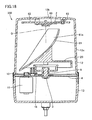
- Fig. 18 is a sectional view taken along the line XVIII-XVIII in Fig. 17;
- Fig. 19 is a perspective view showing a reflecting mirror and a main gear;
- Fig. 20 is a sectional view showing the path of light emitted from a power LED;
- Fig. 21 is a partially fragmented side elevational view showing a rotating lamp according to a fourth embodiment of the present invention;
- Fig. 22 is a sectional view of a portion around a heat radiating portion of the rotating lamp shown in Fig. 21;
- Fig. 23 is a front elevational view of a rotating lamp according to a fifth embodiment of the present invention;
- Fig. 24 is a side sectional view of the rotating lamp shown in Fig. 23;
- Fig. 25 is a side sectional view showing the path of light emitted from a power LED;
- Fig. 26 is a partially fragmented plan view of a reflecting mirror of the rotating lamp;
- Fig. 27 is an enlarged sectional view of the reflecting mirror;
- Fig. 28 is a front elevational view of a rotating lamp according to a sixth embodiment of the present invention;
- Fig. 29 is a side sectional view of the rotating lamp;
- Fig. 30 is a partially fragmented plan view of a reflecting mirror of the rotating lamp;
- Fig. 31 is an enlarged sectional view of a light guide; and
- Fig. 32 is a partially fragmented plan view of the reflecting mirror of the rotating lamp.
- Embodiments of the present invention are now described with reference to Figs. 1 to 32.
- Fig. 1 is a perspective view of a
rotating lamp 100 according to a first embodiment of the present invention. As shown in Fig. 1, therotating lamp 100 comprises ahousing 16 including atransparent globe 12 and a body (substrate) 13. Theglobe 12 is substantially in the form of a hollow cylinder. Thisglobe 12 is provided on its lower surface with anoutward opening 12a having screws formed on the inner peripheral surface thereof. Thebody 13 is also substantially in the form of a hollow cylinder. Thisbody 13 is provided on its upper surface with anoutward opening 13a having screws formed on the outer peripheral surface thereof for fitting with the screws formed on theopening 12a. The screws formed on theopenings globe 12 and thebody 13 with each other, thereby constituting thehousing 16. - A
circular base 20 is arranged in the vicinity of theopenings rotating lamp 100 taken along the line II-II in Fig. 1. As shown in Fig. 2, therotating lamp 100 further comprises ashaft portion 3 arranged in thebody 13, arotatable member 19 rotatably supported by theshaft portion 3, a reflectingmirror 5, arranged on the upper surface of therotatable member 19, having a paraboliclight reflecting surface 5a, alight emitter 1 and adrive portion 21 rotating/driving therotatable member 19. Therotating lamp 100 also comprises a flat chassis (support plate) 4 supporting therotatable member 19 and theshaft portion 3. - The
chassis 4, sized to cover theopening 13a of thebody 13, is in the form of a circular flat plate. Thischassis 4 is made of a material containing metal. Thechassis 4 is preferably made of copper or aluminum. Thecylindrical shaft portion 3 is arranged on the upper surface of the center of thechassis 4. Anut 15 is engaged with the lower end of theshaft portion 3 from under thechassis 4. Thedrive portion 21 driving therotatable member 19 is provided on thechassis 4. - The
shaft portion 3 includes acylindrical portion 3 a and abulge portion 3b outwardly bulging from the upper end of thecylindrical portion 3a. Wires (not shown) are arranged in thecylindrical portion 3 a. Theshaft portion 3 is made of a material containing metal. Theshaft portion 3 is preferably made of copper or aluminum. Therotatable member 19 is arranged on the outer peripheral surface of thecylindrical portion 3 a of theshaft portion 3. - The
rotatable member 19 includes thebase 20 and amain gear 8 arranged on the lower surface of thebase 20. Thebase 20 includes anupper surface 20c in the form of a circular flat plate and aperipheral wall portion 20b suspended from the outer peripheral edge of theupper surface 20c. Acircular opening 20a is formed on the center of theupper surface 20c. Themain gear 8 includes acylindrical portion 8b, a circulardiscoidal portion 8a formed on the upper end of thecylindrical portion 8b, aperipheral wall portion 8d upwardly formed on the outer peripheral edge of thediscoidal portion 8a and mountingportions 8c formed on the upper end of theperipheral wall portion 8d. The mountingportions 8c, outwardly enlarged in diameter from the upper end of theperipheral wall portion 8d, are formed with threaded holes on the upper ends thereof. Therefore, themain gear 8 is so hollowed as to form astorage portion 8e therein. Themain gear 8 and the base 20 are integrally connected with each other through screws fitted with the mountingportions 8c. A plurality of teeth are circumferentially formed on the outer peripheral edge of thediscoidal portion 8a and the outer peripheral surface of theperipheral wall portion 8d. - The
light emitter 1, a flat printedboard 2 provided with thelight emitter 1 and a flange (coupling member) 7 coupling the printedboard 2 and theshaft portion 3 with each other are provided in themain gear 8. - The upper end of the
flange 7 is fixed to the printedboard 2 with screws, while the lower end thereof is embedded in thebulge portion 3b of theshaft portion 3. Therefore, theshaft portion 3, theflange 7, the printedboard 2 and thelight emitter 1 are integrally coupled with each other. Thelight emitter 1 is arranged on the center of the printedboard 2 along the central axis of theshaft portion 3. Theflange 7, made of a material containing metal, is preferably made of copper or aluminum. - The
drive portion 21 includes asupport shaft 18, anintermediate gear 9 supported by thesupport shaft 18, apinion 10 meshing with theintermediate gear 9 and amotor 11 rotating/driving thepinion 10. Thesupport shaft 18 is arranged on a portion of the upper surface of thechassis 4 closer to the outer peripheral edge thereof than therotatable member 19. Themotor 11 is arranged on a side closer to the outer peripheral edge of thechassis 4 than thesupport shaft 18. Thesupport shaft 18 has a large-diametral part 18a provided on the upper surface of thechassis 4 and a small-diametral part 18b, provided on the upper end of the large-diametral part 18a, having a smaller diameter than the large-diametral part 18a. Therefore, thesupport shaft 18 is stepped halfway. Thesupport shaft 18 is engagingly inserted into theintermediate gear 9 for rotatably supporting the same. Theintermediate gear 9 includes adiscoidal portion 9a and acylindrical portion 9b formed on the upper surface of thediscoidal portion 9a. Teeth meshing with those formed on themain gear 8 are formed on the outer peripheral surface of thecylindrical portion 9b, while a plurality of teeth are formed also on the outer peripheral edge of thediscoidal portion 9a. - The
motor 11 is arranged on the lower surface of thechassis 4 so that adrive shaft 11a of thismotor 11 passes through thechassis 4 from the lower surface toward the upper surface thereof. Thepinion 10 is provided on the upper end of thedrive shaft 11a. A plurality of teeth are formed on the outer peripheral surface of thepinion 10 for meshing with the teeth formed on thediscoidal portion 9a of theintermediate gear 9. - Fig. 3 is a perspective view of the printed
board 2, thelight emitter 1 and themain gear 8. As shown in Fig. 3, the mountingportions 8c of themain gear 8 are formed on four positions of the upper end surface of theperipheral wall portion 8d along the circumferential direction. The printedboard 2 is arranged inside the four mountingportions 8c. The printedboard 2, made of a material containing metal, is preferably made of aluminum or copper. - Fig. 4 is a top plan view of the
light emitter 1. As shown in Fig. 4, thelight emitter 1 includes an annular housing (annular member) 33, at least one or more lead frames (platelike members) 31 arranged along the circumferential direction of thehousing 33 so that first ends thereof are arranged in thehousing 33 and light-emittingdiodes 34 provided on second ends of the lead frames 31. - The lead frames 31 are provided on eight portions along the circumferential direction of the
housing 33, and the light-emittingdiodes 34 are arranged on the forward ends of six of the lead frames 31 excluding an opposite pair of opposite lead frames 31. Two triplets of adjacent light-emittingdiodes 34, serially connected with each other bywires 32, are arranged in parallel with each other. The lead frames 31 are in the form of long flat plates having first ends arranged in thehousing 33. The lead frames 31 are provided withextensional portions 35 extending outward from thehousing 33. - Fig. 5 is a wiring diagram showing the state of connection of the light-emitting
diodes 34. As shown in Fig. 5, the two triplets of light-emittingdiodes 34 serially connected with each other are connected in parallel with each other. - While the
rotating lamp 100 according to the first embodiment is provided with the plurality of light-emittingdiodes 34, the present invention is not restricted to this. Fig. 6 is a perspective view showing a modification of thelight emitter 1. As shown in Fig. 6, alight emitter 1 having a power LED (light-emitting diode) 60 arranged on the center of a printedboard 2 may alternatively be employed. Thepower LED 60 emitting a large quantity of light can be utilized as the light source for therotating lamp 100. - Referring to Fig. 2, the reflecting
mirror 5 provided on theupper surface 20c of thebase 20 is arranged in the vicinity of theopening 20a. This parabolic reflectingmirror 5 is arranged to cover thelight emitter 1 arranged on the center of theopening 20a. Therefore, the reflectingmirror 5 extends sideward from behind the light-emittingdiodes 34 shown in Fig. 4 to project frontward beyond the light-emittingdiodes 34 via portions above the light-emittingdiodes 34. The axis P of the parabolic reflectingsurface 5a is parallelized with theupper surface 20c of thebase 20. Thebody 13 is so horizontally arranged as to horizontally direct the axis P. - The optical axis Q of each light-emitting
diode 34 is arranged on or around the rotational axis of the reflectingmirror 5, to intersect with the reflectingmirror 5. In other words, the optical axis Q is arranged on or around the central axis of theshaft portion 3, and parallelized therewith. - The light-emitting
diodes 34 emit conical light substantially symmetrically about the central axis of theshaft portion 3. - On the other hand, the reflecting
mirror 5 intersecting with the optical axes Q of the light-emittingdiodes 34 rotates about theshaft portion 3. Therefore, the light emitted from the light-emittingdiodes 34 toward the reflectingmirror 5 hardly fluctuates upon rotation of the reflectingmirror 5 about theshaft portion 3. In other words, the light emitted from the light-emittingdiodes 34 hits the reflectingmirror 5 at a substantially unfluctuant angle and the reflectingmirror 5 reflects the light in a substantially unfluctuant mode regardless of rotation of the reflectingmirror 5 about theshaft portion 3, so that therotating lamp 100 radiates stationary reflected light regardless of the rotation of the reflectingmirror 5. - According to the first embodiment, the angle of light emission from the light-emitting
diodes 34 is about 170°. Further, the angle formed by a line segment connecting each light-emittingdiode 34 and the lower end of the reflectingmirror 5 with each other and theupper surface 20c of thebase 20 is set to about 10°. In addition, the crossing angle θ formed by a line segment connecting the upper end of the reflectingmirror 5 and a focal point O with each other and another line segment connecting the focal point O and the lower end of the reflectingmirror 5 is set to at least 90° and not more than 120°. Therefore, thelight emitter 1 irradiates light toward the overall surface of the reflectingmirror 5 from the lower end up to the upper end. The focal point O is a point where the substantially parabolic reflectingmirror 5 converges reflected light when receiving parallel light parallel to the axis thereof. - If the crossing angle θ is set smaller than 90°, reflection efficiency of the reflecting
mirror 5 reflecting the light emitted from the light-emittingdiodes 34 having the angle of emission of about 170° is reduced. If the crossing angle θ exceeds 120°, on the other hand, the forward end of the reflectingmirror 5 must disadvantageously be elongated to increase the size of the reflectingmirror 5. - When receiving parallel light parallel to the axis P of the parabolic surface thereof, the reflecting
mirror 5 converges the reflected light on one point. Each light-emittingdiode 34 is arranged on this convergence point of the reflected light. In other words, each light-emittingdiode 34 is arranged on the focal point O of the parallel light applied to the reflectingsurface 5a of the reflectingmirror 5. This focal point O is located on or around the central axis of theshaft portion 3. - In the
rotating lamp 100 having the aforementioned structure, themotor 11 rotates/drives thepinion 10. When thepinion 10 rotates about thedrive shaft 11a, theintermediate gear 9 meshing with thepinion 10 rotates about thesupport shaft 18. When theintermediate gear 9 rotates about thesupport shaft 18, therotatable member 19 fitting with theintermediate gear 9 rotates about theshaft portion 3. Thus, the reflectingmirror 5 provided on the upper surface of thebase 20 rotates about theshaft portion 3 upon rotation of therotatable member 19 about theshaft portion 3. At this time, the focal point O arranged on the central axis of theshaft portion 3 remains unfluctuant on the reflectingsurface 5a upon rotation of the reflectingmirror 5. - The optical axes Q of the light-emitting
diodes 34 are arranged perpendicularly to theupper surface 20c of the base 20 so that the light-emittingdiodes 34 upwardly emit conical light with spreading at the angle of emission of about 170°. On the other hand, the angle θ formed by the line segment connecting the upper end of the reflectingmirror 5 and the focal point O with each other and the line segment connecting the focal point O and the lower end of the reflectingmirror 5 with each other is set to at least 90° and not more than 120°. - If the angle of emission of the light-emitting
diodes 34 is smaller than (θ - 90°) x 2, therefore, the reflectingmirror 5 exhibits reflection efficiency of 100 %. Also when the angle of emission of the light-emittingdiodes 34 is larger than (θ - 90°) x 2, the reflectingmirror 5 intersecting with the optical axes Q of the light-emittingdiodes 34 and covering upper portions of the light-emittingdiodes 34 ensures reflection efficiency of at least 50 %. - According to the first embodiment, the light-emitting
diodes 34 having the large angle of emission of about 170° exhibit high luminous intensity around the optical axes Q. The optical axes Q of the light-emittingdiodes 34 intersect with the reflectingmirror 5, which in turn reliably reflects part of the conical light emitted from the light-emittingdiodes 34 having high luminous intensity. - The
light emitter 1 irradiates the light toward the overall surface of the reflectingmirror 5, so that the reflectingsurface 5a reflects the irradiated light. The parabolic reflectingsurface 5a having the horizontally directed axis P horizontally reflects the light received from the light-emittingdiodes 34 each arranged on the focal point O. In other words, the light reflected by the reflectingsurface 5a horizontally advances in parallel with the axis P of the reflectingsurface 5a from the lower end toward the upper end thereof. - Fig. 7 is a sectional view taken along the line VII-VII in Fig. 2. As shown in Fig. 7, the parabolic reflecting
surface 5a parallelly reflects the light received from thelight emitter 1 including the light-emittingdiodes 34 each arranged on the focal point O. At this time, the reflectingsurface 5a parallelly reflects the light along the axis P thereof from a first end to a second end thereof. Thus, the reflectingmirror 5 parallelly reflects the light received from thelight emitter 1 along the axis P of the reflectingsurface 5a. Therefore, the reflected light hardly spreads but reaches a distant place. - The light emitted from the light-emitting
diodes 34 toward the reflectingmirror 5 remains unfluctuant regardless of the rotation of the reflectingmirror 5 about theshaft portion 3, and hence the reflectingmirror 5 parallelly reflects the light. Thus, the light reflected by the reflectingmirror 5 outgoes toward a distance place. - When the
rotating lamp 100 operates over a long time, the light-emittingdiodes 34 generate heat. However, the lead frames 31 include theextensional portions 35 outwardly extending from thehousing 33, as shown in Fig. 4. Therefore, the heat generated in the light-emittingdiodes 34 is first transferred to theextensional portions 35 of the lead frames 31, and outwardly dissipated through theextensional portions 35. Thelight emitter 1 including the light-emittingdiodes 34, the printedboard 2, theflange 7 and theshaft portion 3 are integrated with each other as shown in Fig. 2. Thus, the heat generated in the light-emittingdiodes 34 and transferred to the lead frames 31 as shown in Fig. 4 is successively transferred to the printedboard 2, theflange 7 and theshaft portion 3 shown in Fig. 2 and dissipated outward. Theshaft portion 3, theflange 7 and the printedboard 2 made of the material containing metal excellently transfer and dissipate the heat. When made of copper or aluminum, theshaft portion 3, theflange 7 and the printedboard 2 exhibit high heat transfer coefficients, to excellently dissipate the heat outward. - The heat transferred to the
shaft portion 3 is also excellently transferred to thechassis 4 also made of the material containing metal, to be excellently dissipated outward. When thechassis 4 is made of copper or aluminum, the heat is more excellently transferred to thechassis 4 and dissipated outward. - In addition, the
light emitter 1 is arranged in therotatable member 8 or downward beyond the center of the reflectingsurface 5a, whereby a mechanism dissipating the heat transferred from the light-emittingdiodes 34 can be stored in therotatable member 8 and the printedboard 2 etc. can be inhibited from blocking the light reflected by the reflectingsurface 5a. Further, thelight emitter 1 is so arranged closer to therotatable member 8 that a heat radiating member such as the printedboard 2 or the like can be arranged immediately under thelight emitter 1 for excellently dissipating the heat transferred from the light-emittingdiodes 34 without blocking the reflected light. - In the
rotating lamp 100 according to the first embodiment, the reflectingmirror 5 reflects part of the light emitted from the light-emittingdiodes 34 at an angle of emission of at least 0° and not more than θ° with high reflection efficiency. Thus, therotating lamp 100 can convert most of the light received from the light-emittingdiodes 34 to parallel light for reliably delivering the light to a distant place. - In particular, the
rotating lamp 100 according to the first embodiment, capable of reliably reflecting part of the conical light emitted from the light-emittingdiodes 34 having high luminous intensity, can radiate parallel light having high luminous intensity. - Further, the
rotating lamp 100, capable of dissipating the heat generated in the light-emittingdiodes 34 outward, can elongate the lives of the light-emittingdiodes 34. - A second embodiment of the present invention is described with reference to Figs. 8 to 16. Fig. 8 is a perspective view of a
rotating lamp 200 according to the second embodiment. As shown in Fig. 8, therotating lamp 200 includes anauxiliary reflecting mirror 50 opposed to a reflectingmirror 5. Thisauxiliary reflecting mirror 50 includes asupport portion 50a fixed to anupper surface 20c of abase 20 and asubreflecting portion 50b provided on the forward end of thesupport portion 50a. - The
auxiliary reflecting mirror 50 and alight emitter 1 are arranged along an axis P of a reflectingsurface 5a, and light-emittingdiodes 34 provided in thelight emitter 1 are arranged between the reflectingmirror 5 and theauxiliary reflecting mirror 50. - Fig. 9 is a side sectional view of the
rotating lamp 200 shown in Fig. 8. As shown in Fig. 9, theauxiliary reflecting mirror 50 has an arcuatelycurved subreflecting surface 50c opposed to the reflectingmirror 5. Thecurved subreflecting surface 50c is inclined to be gradually increased in height as separated from the light-emittingdiodes 34. Theauxiliary reflecting mirror 50 is arranged in a direction along the axis P, to be closer to the outer peripheral edge of theupper surface 20c than a focal point O. - Fig. 10 is a sectional view taken along the line X-X in Fig. 9. As shown in Fig. 10, the circumferential length of the
subreflecting surface 50c of theauxiliary reflecting mirror 50 is gradually increased as separated from the focal point O. Therefore, thesubreflecting surface 50c is sectorially formed about the focal point O as viewed from above. Thelight emitter 1 is arranged inside thesubreflecting surface 50c, whose lower end is arranged along the outer peripheral edge of thelight emitter 1. Thesubreflecting surface 50c is symmetrically arranged with respect to the axis P of the reflectingsurface 5a. While the angle of thesubreflecting surface 50c is set to about 90° according to the second embodiment, the present invention is not restricted to this. - Fig. 11 is a side sectional view of the
rotating lamp 200 shown in Fig. 8. As shown in Fig. 11, thesubreflecting portion 50b is so formed that the width thereof is gradually increased upward from theupper surface 20c of thebase 20. The remaining structure of therotating lamp 200 according to the second embodiment is similar to that of therotating lamp 100 according to the aforementioned first embodiment. It is assumed that the height H of thesubreflecting portion 50b and thesubreflecting surface 50c corresponds to the distance between the upper end of thesubreflecting portion 50b and theupper surface 20c of thebase 20. - Fig. 12 is a top plan view of the
rotating lamp 200 according to the second embodiment. As shown in Fig. 12, the reflectingmirror 5 reflects light received from thelight emitter 1 outward as parallel light. Fig. 13 is a side sectional view of therotating lamp 200. As shown in Fig. 13, therotating lamp 200 horizontally radiates the light received from thelight emitter 1 and reflected by the reflectingmirror 5. In other words, the reflectingmirror 5 reflects the light received from thelight emitter 1 as parallel light parallel to the axis P of the reflectingsurface 5a also in therotating lamp 200 according to the second embodiment, similarly to the aforementioned first embodiment. - Fig. 14 is a side sectional view of the
rotating lamp 200 showing reflection efficiency for the light received from thelight emitter 1. As shown in Fig. 14, thesubreflecting surface 50c reflects a region of the light received from thelight emitter 1 held between a line segment passing through the focal point O and the upper end of thesubreflecting surface 50c and another line segment passing through the focal point O and the lower end of thesubreflecting surface 50c. A retroreflective region reflected by thesubreflecting surface 50c, varying with the height H of thesubreflecting surface 50c, is widened as the height H of thesubreflecting surface 50c is increased. On the other hand, therotating lamp 200 outwardly radiates part of the light received from the light-emittingdiodes 34 passing through the clearance between the lower end of thesubreflecting surface 50c and the outer peripheral edge of anopening 20a without reflecting the same by thesubreflecting surface 50c. Further, therotating lamp 200 directly radiates part of the light received from the light-emittingdiodes 34 passing through the clearance between the upper ends of thesubreflecting surface 50c and the reflectingmirror 5. I is assumed that β represents the total angle of emission of the light-emittingdiodes 34, and α1 represents the angle at the focal point O in the angles formed by the focal point O and the upper and lower ends of thesubreflecting surface 50c. It is also assumed that α2 represents the angle of the focal point O in a region where the reflectingmirror 5 reflects the light from the light-emittingdiodes 34. In addition, γ1 represents the angle of the light outgoing from the light-emittingdiodes 34 and passing through the clearance between the lower end of thesubreflecting surface 50c and the outer peripheral edge of theopening 20a at the focal point O, and γ2 represents the angle of the light outgoing from the light-emittingdiodes 34 and passing through the clearance between the upper ends of thesubreflecting surface 50c and the reflectingmirror 5 at the focal point O. - The angle γ1 of the light outgoing from the light-emitting
diodes 34 and passing through the clearance between the lower end of thesubreflecting surface 50c and the outer peripheral edge of theopening 20a at the focal point O is small. The angle γ2 of the light outgoing from the light-emittingdiodes 34 and passing through the clearance between the upper ends of thesubreflecting surface 50c and the reflectingmirror 5 at the focal point O is also small. Therotating lamp 200 directly radiates small part of γ1 + γ2 in the total angle of emission β of the light emitted from thelight emitter 1. - In other words, the
rotating lamp 200 can utilize the light originally directly outwardly emitted from the light-emittingdiodes 34 due to theauxiliary reflecting mirror 50, for improving the reflection efficiency. - Fig. 15 is a side sectional view of the
rotating lamp 200. As shown in Fig. 15, the reflectingmirror 5 horizontally reflects the light emitted from thelight emitter 1 toward the lower end of the reflectingmirror 5. Thesubreflecting surface 50c reflects the light emitted from thelight emitter 1 and reflected by the lower end of the reflectingmirror 5 toward the reflectingmirror 5. The reflectingmirror 5 reflects the light reflected by thesubreflecting surface 50c again. Therotating lamp 200 radiates the light reflected by the reflectingmirror 5 again downward beyond the horizontal direction. - Thus, the
rotating lamp 200 radiates the light emitted from thelight emitter 1 and reciprocated between thesubreflecting surface 50c and the reflectingsurface 5a downward beyond the horizontal direction as viewed from a side portion. In other words, the quantity of the light radiated downward beyond the horizontal direction is increased as the height H of thesubreflecting surface 50c is increased, while the quantity of light parallelized by the reflectingmirror 5 and radiated outward is reduced. Therefore, the height H of thesubreflecting surface 50c is properly varied with the application, the set position etc. of therotating lamp 200. - When it is necessary to deliver the light from the
rotating lamp 200 to a distant place, the height H of thesubreflecting surface 50c is set low. When it is necessary to ensure visibility from below by setting therotating lamp 200 on a position higher than the human viewpoint, for example, the height H of thesubreflecting surface 50c is set high. - Fig. 16 is a sectional view taken along the line XVI-XVI in Fig. 15. As shown in Fig. 16, the light emitted from the
light emitter 1 advances toward the reflectingmirror 5 as radiation. The reflectingmirror 5 reflects the light received from thelight emitter 1 in parallel with the axis P. This parallel light is reflected by thesubreflecting surface 50c, thereafter temporarily converged, and then diffused. The reflectingmirror 5 reflects the light reflected by thesubreflecting surface 50c again. The light reflected by the reflectingmirror 5 again is converged on a position separated from the reflectingmirror 5. - The
rotating lamp 200 according to the second embodiment can radiate the light downward for improving visibility from below by reflecting the light received from thelight emitter 1 with the reflectingmirror 5, reflecting this reflected light with theauxiliary reflecting mirror 50 and further reflecting the light reflected by theauxiliary reflecting mirror 50 with the reflectingmirror 5 again. Theauxiliary reflecting mirror 50 can reflect at least partial light emitted from thelight emitter 1 but not directed toward the reflectingmirror 5 toward the reflectingmirror 5, for improving the reflection efficiency. - The
rotating lamp 200 according to the second embodiment can also deliver the light, emitted from thelight emitter 1 and directly reflected by the reflectingmirror 5 in a parallel manner, to a distant place similarly to the aforementioned first embodiment. - Further, the
rotating lamp 200 according to the second embodiment, having the structure similar to that of therotating lamp 100 according to the aforementioned first embodiment, can attain effects similar to those of therotating lamp 100 according to the first embodiment. - A
rotating lamp 300 according to a third embodiment of the present invention is described with reference to Figs. 17 to 20. - Fig. 17 is a perspective view of the
rotating lamp 300 according to the third embodiment. As shown in Fig. 17, therotating lamp 300 comprises ahousing 16, apower LED 60 arranged in thehousing 16 for serving as a light source, a printedboard 2 on which thepower LED 60 is arranged, aheat radiating portion 62 mounted with thepower LED 60 through the printedboard 2, a reflectingmirror 61 and apower supply portion 67. - A
globe 12 includes a circularupper wall 12b and aperipheral wall 12c formed on the peripheral edge of theupper wall 12b. Theheat radiating portion 62 is directly fixed to theupper wall 12b through a plurality ofbosses 63. Theheat radiating portion 62 is in the form of a circular plate, and fixed to theupper wall 12b with a small space. The printedboard 2 is fixed to the surface of theheat radiating portion 62 closer to the inner side of thehousing 16. Thepower LED 60 is fixed to a substantially central part of the printedboard 2. - Lead
wires 66 are provided between thepower supply portion 67 and the printedboard 2 for supplying electricity from thepower supply portion 67 to thepower LED 60. First ends of theselead wires 66 are connected to the printedboard 2. Intermediate portions of thelead wires 66 extending from the printedboard 2 toward theperipheral wall 12c of theglobe 12 are held by a leadwire holding portion 65 on the side of theupper wall 12b. Thelead wires 66 are suspended from the upper end toward the lower end of theperipheral wall 12c along the inner wall surface of theperipheral wall 12c, and connected to thepower supply portion 67 on the lower ends thereof. Thelead wires 66, covered with an insulating material, have small diameters. Thepower LED 60 serving as a light source is fixed to theupper wall 12b through theheat radiating portion 62, whereby no support portion or the like may be arranged for supporting theheat radiating portion 62 and thepower LED 60 on the side of abody 13, not to suppress progress of light reflected by a reflectingsurface 61 a. - Fig. 18 is a sectional view taken along the line XVIII-XVIII in Fig. 17. As shown in Fig. 18, a
shaft portion 3 is arranged on the upper surface of achassis 4 for rotatably supporting amain gear 8, to which abase 20 is fixed. The reflectingmirror 61 is fixed to the upper surface of thebase 20. According to the third embodiment, a driving mechanism for rotating the reflectingmirror 61 and thepower LED 60 serving as a light source are separated from each other. - The
heat radiating portion 62 for cooling the light source is arranged not in the driving mechanism but on a position separated from the driving mechanism, whereby a large space can be ensured for arranging theheat radiating portion 62. In other words, the driving mechanism is arranged on the side of thebody 13 so that theheat radiating portion 62 is arranged substantially on the overall surface of theupper wall 12b. - Only the
heat radiating portion 62 is arranged on theupper wall 12b, whereby a wide area can be ensured for a platelike member constituting theheat radiating portion 62. Further, theheat radiating portion 62 arranged on the overall surface of theupper wall 12b does not suppress progress of light reflected by the reflectingsurface 61a and light received from thepower LED 60 not passing through theupper wall 12b. - The reflecting
mirror 61 is arranged under thepower LED 60. This reflectingmirror 61 includes the reflectingsurface 61a reflecting the light received from thepower LED 60. The reflectingsurface 61 a of the reflectingmirror 61 is arranged gradually toward theupper wall 12b from a portion close to anopening 12a of theglobe 12 inward. This reflectingsurface 61a is substantially in the form of a paraboloid. In other words, the reflectingsurface 61 a is constituted of part of a paraboloid, and thepower LED 60 is arranged on the focal position of the reflectingsurface 61a. In therotating lamp 300 according to the third embodiment, the reflectingsurface 61a is arranged toward theupper wall 12b. The reflectingmirror 61 is formed to project frontward beyond thepower LED 60 from behind thepower LED 60 through a portion above the optical axis Q of thepower LED 60. - The
power LED 60 serving as a light source and the driving mechanism are so arranged independently of each other that the driving mechanism is compactly constituted, amotor 11 or the like is arranged in the vicinity of theshaft portion 3 and the height of the driving mechanism is reduced. Therefore, wide spaces are ensured above thebase 20 and in the vicinity of theperipheral wall 12c respectively. The lower end of the reflectingmirror 61 is arranged downward beyond the upper surface of the base 20 in the wide space formed above thebase 20. Therefore, a wide area is ensured for the reflectingsurface 61 a of the reflectingmirror 61. - The optical axis Q of the
power LED 60 is arranged downward to intersect with the reflectingsurface 61a. Further, the optical axis Q of thepower LED 60 is arranged on or around the central axis of theshaft portion 3. - Fig. 19 is a perspective view showing the reflecting
mirror 61 and themain gear 8. As shown in Fig. 19, the width of the reflectingmirror 61 is gradually increased upward from thebase 20. The width of the reflectingmirror 61 is maximized on the upper end thereof. In other words, the upper end of the reflectingmirror 61 covers the side portion of thepower LED 60 shown in Fig. 18. - Fig. 20 is a sectional view showing the path of the light from the
power LED 60. Thepower LED 60 is arranged on the focal position of the reflectingsurface 61a as shown in Fig. 20, so that the reflectingsurface 61 a parallelly reflects the light received from thepower LED 60. Thepower LED 60 conically emits the light along the optical axis Q. The upper end of the reflectingmirror 61 is arranged on the path of light outgoing from thepower LED 60 and passing through a position intersecting with the optical axis Q at the largest angle. A substantially central portion of the reflectingmirror 61 is arranged on or around the optical axis Q of thepower LED 60, while the lower end of the reflectingmirror 61 extends toward the lower surface of thebase 20. Thus, the reflectingsurface 61a reflects the light received from thepower LED 60 over a wide range. The reflectingsurface 61 a, arranged over a wide range from around thepower LED 60 toward the lower surface of thebase 20, ensures a wide sectional area for the path of the light reflected by the same. - When emitting light over a long time, the
power LED 60 generates heat. The heat generated in thepower LED 60 is first transferred to the printedboard 2. The printedboard 2, made of a material including a heat-transferable metallic material or the like, excellently dissipates the heat outward and transfers the same to theheat radiating portion 62. Substantially the overall surface of the printedboard 2 is in contact with theheat radiating portion 62, for excellently transferring the heat to theheat radiating portion 62. Theheat radiating portion 62 is formed by a platelike member substantially covering the overall surface of theupper wall 12b to ensure a wide contact area with the air, and made of a material including a heat-transferable metallic material for excellently dissipating the heat outward. Further, theheat radiating portion 62 is arranged to be slightly separated from theupper wall 12b, for excellently dissipating the heat also from the surface closer to theupper wall 12b. Thus, the heat generated from thepower LED 60 is excellently dissipated outward through the printedboard 2 and theheat radiating portion 62, so that thepower LED 60 hardly stores the heat and is inhibited from reaching a high temperature. - The
rotating lamp 300 according to the third embodiment, ensuring a wide area for the reflectingsurface 61 a, can improve reflection efficiency for the light emitted from thepower LED 60. - Further, the
rotating lamp 300 ensuring the area for the reflectingsurface 61a can ensure a wide sectional area for the path of the light reflected by the reflectingsurface 61a and improve visibility. - In addition, the
rotating lamp 300 ensuring the contact area between theheat radiating portion 62 and the printedsubstrate 2 can excellently transfer the heat from thepower LED 60 to theheat radiating portion 62 and dissipate the heat through theheat radiating portion 62 having excellent heat radiation efficiency, for excellently cooling thepower LED 60. Thus, the life of thepower LED 60 serving as a light source can be elongated. - A
rotating lamp 400 according to a fourth embodiment of the present invention is described with reference to Figs. 21 and 22. - Fig. 21 is a partially fragmented side elevational view of the
rotating lamp 400 according to the fourth embodiment. As shown in Fig. 21, aheat radiating portion 62 and a driving mechanism driving a reflectingmirror 61 are separately arranged also in therotating lamp 400 according to the fourth embodiment. In other words, theheat radiating portion 62 is arranged on the inner wall surface of anupper wall 12b of aglobe 12. - Fig. 22 is a sectional view of a portion around the
heat radiating portion 62 of therotating lamp 400 shown in Fig. 21. As shown in Fig. 22, theheat radiating portion 62 includes aradiator plate 62a fixed to the inner wall surface of theupper wall 12b, anotherradiator plate 62b arranged on the lower surface of theradiator plate 62a with an area smaller than that of theradiator plate 62a and still anotherradiator plate 62c arranged on the lower surface of theradiator plate 62b with an area larger than that of theradiator plate 62b. In other words, theheat radiating portion 62 is formed by superposing platelike members having different areas with each other, for ensuring a surface area for coming into contact with the air. The radiator plate 63c is substantially identical in size to a printedboard 2. Theradiator plate 62a closer to theupper wall 12b is fixed to theupper wall 12b in a state slightly separated therefrom. Theheat radiating portion 62 may alternatively be formed by stackingradiator plates upper wall 12b and still anotherradiator plate 62b having an area smaller than those of theradiator plates rotating lamp 400 is similar to that of therotating lamp 300 according to the aforementioned third embodiment, and elements similar to those of the third embodiment are denoted by the same reference numerals, not to repeat redundant description. - In the
rotating lamp 400 having the aforementioned structure, heat generated from apower LED 60 is transferred to the printedboard 2. The heat received by the printedboard 2 is transferred to theradiator plate 62b substantially from the overall upper surface of the printedboard 2. The heat received by theradiator plate 62b is transferred to theradiator piaie 62c substantially from the overall lower surface of theradiator plate 62c. The heat received by theradiator plate 62c is transferred to theradiator plate 62a substantially from the overall upper surface of theradiator plate 62c. Thus, the heat is excellently transferred from theradiator plate 62b to theradiator plate 62c and from theradiator plate 62c to theradiator plate 62a through the surfaces of theradiator plate 62c. - The
rotating lamp 400 having the aforementioned structure can increase the quantity of heat dissipated from theheat radiating portion 62 outward due to the large surface area of theheat radiating portion 62. Thus, therotating lamp 400 can excellently cool thepower LED 60. In addition, the heat generated in thepower LED 60 can be excellently transferred to theradiator plates 62a to 62c and excellently dissipated outward through theradiator plates 62a to 62c. - A
rotating lamp 500 according to a fifth embodiment of the present invention is described with reference to Figs. 23 to 27. Elements similar to those of the aforementioned first embodiment are denoted by the same reference numerals, not to repeat redundant description. Fig. 23 is a front elevational view of therotating lamp 500 according to the fifth embodiment. As shown in Fig. 23, a plurality ofrecesses 5A and a plurality ofprojections 5B are formed substantially on the overall surface of a reflectingsurface 5a of therotating lamp 500. Therecesses 5A and theprojections 5B extend perpendicularly to the rotational axis of a reflectingmirror 5A, for example, to intersect with the rotational axis. The plurality ofrecesses 5A and the plurality ofprojections 5B are alternately formed toward the rotational axis of the reflectingmirror 5. Thus, the reflectingsurface 5a formed with the plurality ofrecesses 5A and the plurality ofprojections 5B reflects light outgoing from apower LED 60 and hitting the reflectingsurface 5a in various directions. - Fig. 24 is a side sectional view of the
rotating lamp 500 shown in Fig. 23. Referring to Fig. 24, reflecting surfaces (first reflecting surfaces) 5a1 located on the surfaces of therecesses 5A formed on the reflectingsurface 5a are in the form of paraboloids, while reflectingsurfaces 5b located on the surfaces of theprojections 5B area arranged in directions intersecting with the paraboloids. Alight emitter 1 having thepower LED 60 is arranged on the focal points O of the parabolic reflecting surfaces 5a1. Fig. 25 is a side elevational view showing the path of the light emitted from thepower LED 60, and Fig. 26 is a partially fragmented plan view of the reflectingmirror 5 of therotating lamp 500. Both of these figures show the state of reflection of the light emitted from thelight emitter 1. When abody 13 is horizontally arranged, the light emitted from thepower LED 60 radially spreads and is horizontally reflected by the reflecting surfaces 5a1 of therecesses 5A in a parallel manner, as shown in Figs. 25 and 26. - When hitting the reflecting
surfaces 5b of theprojections 5B, on the other hand, the light emitted from thepower LED 60 is reflected to intersect with the light reflected by the reflecting surfaces 5a1, as shown in Fig. 25. Therefore, the light emitted from thepower LED 60 is reflected by the reflectedmirror 5 both in the parallel direction and the direction perpendicular thereto, whereby therotating lamp 500 can ensure visibility on the front surface thereof and a position slightly deviating therefrom. - Fig. 27 is an enlarged sectional view of the reflecting
mirror 5 showing the path of the light emitted from thepower LED 60. As shown in Fig. 27, the reflectingsurface 5a includes the parabolic reflecting surfaces 5a1 and reflecting surfaces 5a2 and 5a3 arranged on both sides of the reflecting surfaces 5a1 respectively. The reflecting surfaces 5a1, 5a2 and 5a3 are successively alternately arranged from the side of asubstrate 13 shown in Fig. 25 toward the upper end of the reflectingmirror 5. The reflecting surfaces 5a2 and 5a3 are formed on the surfaces of theprojections 5B, and the reflecting surfaces 5a2 are arranged oppositely to the reflecting surfaces 5a3 with respect to the reflecting surfaces 5a1. - The reflecting surfaces 5a2 are more inclined toward the
power LED 60 than the adjacent reflecting surfaces 5a1 from thesubstrate 13 shown in Fig. 25 toward the upper end of the reflectingmirror 5. - Therefore, the reflecting surfaces 5a2 reflect the light received from the
power LED 60 more toward thesubstrate 13 shown in Fig. 25 than the light reflected by the reflecting surfaces 5a1. When thesubstrate 13 is horizontally arranged, the reflecting surfaces 5a2 reflect the light downward beyond the horizontal direction. Therefore, therotating lamp 500 can ensure visibility from below also when the same is arranged above the line of sight of an observer. - The widths of the reflecting surfaces 5a2 and 5a3 are reduced and increased respectively from the
substrate 13 toward the upper end of the reflectingmirror 5. - Therefore, the areas of the reflecting surfaces 5a2 closer to the
substrate 13 shown in Fig. 13 are smaller than those of the reflecting surfaces 5a2 closer to the upper end of the reflectingmirror 5, while the areas of the reflecting surfaces 5a3 closer to the upper end of the reflectingmirror 5 are smaller than those of the reflecting surfaces 5a3 closer to thesubstrate 13. - Thus, a
rotatable member 8 and thesubstrate 13 shown in Fig. 25 are inhibited from blocking downwardly directed reflected light, so that therotating lamp 500 can excellently radiate the reflected light downward. Further, reflected light directed toward the upper end of the reflectingmirror 5 beyond parallel light is widely ensured on the side of the reflectingmirror 5 closer to thesubstrate 13, whereby therotating lamp 500 can also ensure visibility from above. - On the other hand, the widths of the reflecting surfaces 5a1 are substantially uniform from the
substrate 13 toward the upper end of the reflectingmirror 5, regardless of the positions of the reflecting surfaces 5a1. Therefore, therotating lamp 500 substantially uniformly radiates parallel light substantially from the overall reflectingsurface 5a toward thesubstrate 13. This parallel light can reach a distant place, whereby therotating lamp 500 can also ensure visibility from the front surface also in the distant place. - A
rotating lamp 600 according to a sixth embodiment of the present invention is described with reference to Figs. 28 to 32. Elements similar to those of therotating lamp 100 according to the aforementioned first embodiment are denoted by the same reference numerals, not to repeat redundant description. Fig. 28 is a front elevational view of therotating lamp 600 according to the sixth embodiment. Therotating lamp 600 includes a transparentlight guide 70 arranged in aglobe 12, as shown in Fig. 28. Thislight guide 70 is made of a transparent resin material such as acrylic or polycarbonate or a transparent nonplastic material such as glass. - Thus, the
light guide 70 is so formed by a transparent member that therotating lamp 600 can inhibit thelight guide 70 from blocking light reflected by a reflectingsurface 5a. Therefore, therotating lamp 600 can ensure visibility with the light reflected by the reflectingsurface 5 a. - Fig. 29 is a side sectional view of the
rotating lamp 600, and Fig. 30 is a partially fragmented top plan view of a reflectingmirror 5 of therotating lamp 600. As shown in Fig. 29, thelight guide 70 includes a fixedportion 74 fixed to the upper surface of a base 20 to extend toward apower LED 60, aneck portion 72 provided on the fixedportion 74 and arranged on the upper surface of thepower LED 60, a condensingportion 73 formed on the lower end of theneck portion 72 and ascattering portion 71 provided on the forward end of theneck portion 72. - As shown in Figs. 29 and 30, the scattering
portion 71 semicircularly extends and projects from the forward end of theneck portion 72 oppositely to the reflectingsurface 5a. A reflectingsurface 71a of the scatteringportion 71 closer to the reflectingsurface 5a is in the form of a semicircular truncated cone. - Fig. 31 is an enlarged sectional view of the
light guide 70. As shown in Figs. 31 and 29, a surface of the condensingportion 73 opposed to thepower LED 60 is formed by aconvex lens 73a, for example, and the condensingportion 73 is located oppositely to the reflectingsurface 5a with respect to the optical axis Q of thepower LED 60. - Therefore, the condensing
portion 73 can condense part of light emitted from thepower LED 60 not hitting the reflectingsurface 5a, for improving utilization efficiency for the light emitted from thepower LED 60. Theconvex lens 73a bends the light received from thepower LED 60 toward theneck portion 72 and the scatteringportion 71. While the surface of the condensingportion 73 opposed to thepower LED 70 is formed by theconvex lens 73 a in the sixth embodiment, the present invention is not restricted to this. In other words, this surface may alternatively be formed by a plane lens or a concave lens so far as the same can bend the light received from thepower LED 60 toward theneck portion 72 and the scatteringportion 71. - The light supplied from the
power LED 60 to theneck portion 72 is reflected by theneck portion 72 and guided to the scatteringportion 71. The angle of inclination of the reflectingsurface 71a is set to be capable of totally reflecting the light received from theneck portion 72, and properly set in response to the member constituting thelight guide 70. - A plurality of
convex lenses 71b are formed on the surface of the scatteringportion 71 opposite to the reflectingsurface 71a. Theseconvex lenses 71b scatter the light reflected by the reflectingsurface 71a perpendicularly to parallel light reflected by the reflectingsurface 5a shown in Fig. 29. Thus, therotating lamp 600, capable of scattering the light received from thepower LED 60 on the scatteringportion 71, can ensure visibility not only from the front surface of therotating lamp 60 but also from below and from above the same. - The
light guide 70 is uprightly provided on thepower LED 60 and the scatteringportion 71 is arranged closer to the upper end of the reflectingmirror 5 than the base 20, whereby the scatteringportion 71 can be visually recognized not only from the front surface of therotating lamp 600 but also from below the same. Thus, an observer can excellently visually recognize the light from the scatteringportion 71 also when observing therotating lamp 600 from below, and therotating lamp 600 is improved in visibility from below. - It seems to the observer observing the
power LED 60 through thelight guide 70 as if the scatteringportion 71 itself emits light. - The size of the virtual light source formed by the scattering
portion 71 can be ensured due to the plurality oflenses 71b for scattering light stacked with each other from thesubstrate 13 toward the upper end of the reflectingmirror 5. - The
lenses 71b are formed to project oppositely to the reflectingmirror 5 shown in Fig. 29 from thesubstrate 13 toward the upper end of the reflectingmirror 5. The reflectingsurface 71a is inclined oppositely to the reflectingmirror 5 from thesubstrate 13 toward the upper end of the reflectingmirror 5, whereby the scatteringportion 71 has a substantially uniform thickness in the horizontal direction from thesubstrate 13 toward the upper end of the reflectingmirror 5. - Thus, the
light guide 70 can be excellently manufactured by a technique such as extrusion molding so that the same can be substantially uniformly cooled due to the substantially uniform thickness of the scatteringportion 71. - As shown in Fig. 29, the
neck portion 72 of thelight guide 70 is inclined oppositely to the reflectingsurface 5a with respect to the optical axis Q. Thus, a shadow of thelight guide 70 formed on the reflectingsurface 5a can be located on the upper end of the reflectingsurface 5a due to theinclined neck portion 72. In other words, thelight guide 70 blocks the light received from thepower LED 60 against the reflectingsurface 5a located on a straight line connecting thepower LED 60 and thelight guide 70 with each other, to weaken the reflected light on this portion. The weakened portion of the reflected light is so located on the upper end of the reflectingmirror 5 that the same is inconspicuous. - The
light guide 70 is located outward beyond a region defined by a plane connecting thepower LED 60 and the upper end of the reflectingmirror 5 and the reflectingsurface 5a with respect to the reflectingmirror 5, so that the reflectingsurface 5a can be inhibited from receiving the shadow of thelight guide 70 and forming the weakened portion of the light reflected by the reflectingsurface 5a. Thelight guide 70 is so arranged to extend on the center line of ashaft portion 3 shown in Fig. 29 that the same seems to be located on a constant position upon driving of therotating lamp 600. While theneck portion 72 has a conical shape according to the sixth embodiment, the present invention is not restricted to this but theneck portion 72 may alternately have a semicylindrical shape having a substantially constant width in the horizontal direction from thesubstrate 13 toward the upper end of the reflectingmirror 5, for example. Thus, thelight guide 70 can be excellently manufactured so that the same can be substantially uniformly cooled due to the substantially uniform thickness of theneck portion 72 in the horizontal direction from thesubstrate 13 toward the upper end of the reflectingmirror 5. - Fig. 32 is a partially fragmented plan view of the reflecting
mirror 5 of the rotating lamp showing the path of the light emitted from thepower LED 60. As shown in Fig. 32, the light emitted from thepower LED 60 is radially scattered about thepower LED 60 through thelight guide 70 as viewed from above, and the angle of emission is set to about 180°. Further, the light is scattered by the scatteringportion 71 also upward and downward as shown in Fig. 31, so that therotating lamp 600 radiates the light also upward and downward in the range of about 180° as viewed from above and the observer can observe the light scattered by the scatteringportion 71 from various positions. - While the scattering
portion 71 and theneck portion 72 cover thepower LED 60 over a semicircular region of about 180° about thepower LED 60 in plan view in therotating lamp 600 according to the sixth embodiment, the present invention is not restricted to this but the scatteringportion 71 and theneck portion 72 may alternatively cover thepower LED 60 over a region of at least or not more than about 180°. While the reflectingsurface 5a is arranged to cover a peripheral portion of thepower LED 60 opposite to thelight guide 60 at an angle of about 180° as viewed from above, the present invention is not restricted to this but the reflectingsurface 5a may alternatively cover the periphery of thepower LED 60 at another angle. - In other words, the angle at which the
scattering portion 71 and theneck portion 72 cover the periphery of thepower LED 60 may be increased while reducing the angle at which the reflectingmirror 5 covers the periphery of thepower LED 60, in order to ensure visibility of thelight guide 70. The angles at which thelight guide 70 and the reflectingmirror 5 cover the periphery of thepower LED 60 is properly varied with the balance between visibility through thelight guide 70 and that through the reflectingmirror 5. - Although the present invention has been described and illustrated in detail, it is clearly understood that the same is by way of illustration and example only and is not to be taken by way of limitation, the spirit and scope of the present invention being limited only by the terms of the appended claims.
- The rotating lamp according to the present invention can deliver light to a distance place.
Claims (17)
- A rotating lamp comprising:a substrate (13);a translucent globe (12) mounted on said substrate;a shaft portion (3) set in said substrate;a rotatable member (19) rotatably supported by said shaft portion (3);a reflecting mirror (5) arranged on the upper surface of said rotatable member (19) and at least partially constituted of a parabolic reflecting surface;a light-emitting diode (34) functioning as a light source; anda drive portion (21) rotating/driving said rotatable member (19), andarranging said light-emitting diode (34) and said reflecting mirror (5) so that the optical axis of said light-emitting diode (34) and said reflecting surface of said reflecting mirror (5) intersect with each other.
- The rotating lamp according to claim 1, wherein
said light-emitting diode (34) is arranged on a focal position (O) upon irradiation of parallel light toward said reflecting surface, and
said reflecting mirror (5) has a shape extending sideward from behind said light-emitting diode (34) to project frontward beyond said light-emitting diode (34) via a portion above said light-emitting diode (34). - The rotating lamp according to claim 1 or 2, further comprising an auxiliary reflecting mirror (50) arranged on the upper surface of said rotatable member (19) and opposed to said reflecting mirror (5), wherein
said light-emitting diode (34) is arranged between said auxiliary reflecting mirror (50) and said reflecting mirror (5). - The rotating lamp according to claim 3, wherein
said auxiliary reflecting mirror (50) has an arcuately curved surface opposed to said reflecting mirror (5), and
said curved surface is inclined to be increased in height and gradually increased in circumferential length as separated from said light-emitting diode (34). - The rotating lamp according to any of claims 1 to 4, wherein
a light emitter (1) having said light-emitting diode (34) includes an annular member (33) and at least one platelike member (31) arranged along the circumferential direction of said annular member (33) so that a first end is arranged in said annular member (33), and
said platelike member (31) includes an extensional portion extending outward from said annular member. - The rotating lamp according to claim 5, further comprising:a printed board (2) provided with said light emitter (1), anda coupling member (7) coupling said printed board (2) and said shaft portion (3) with each other, whereinsaid shaft portion (3), said printed board (2) and said coupling member are made of a material containing metal.
- The rotating lamp according to any of claims 1 to 6, further comprising a flat support plate (4) supporting said rotatable member (19) and said shaft portion (3), wherein
said support plate (4) is made of a material containing metal. - The rotating lamp according to any of claims 1 to 7, wherein
said light-emitting diode (34) is fixed to the upper wall of said globe (12). - The rotating lamp according to claim 8, further comprising a heat radiating portion (62) capable of dispersing heat generated in said light-emitting diode (34) outward, wherein
said light-emitting diode (34) is fixed to the upper wall of said globe (12) through said heat radiating portion. - The rotating lamp according to claim 9, wherein
said heat radiating portion (62) includes a printed board mounted with said light-emitting diode (34) on the surface thereof and a radiator plate (62a) mounted with said printed board (2) on the surface thereof, and
said radiator plate (62a) is fixed to the upper wall of said globe. - The rotating lamp according to any of claims 8 to 10, further comprising a lead wire for supplying power to said light-emitting diode (34), wherein
said lead wire (66) is arranged along the inner surface of said globe (12). - The rotating lamp according to any of claims 1 to 11, wherein
said reflecting mirror (5) includes said parabolic first reflecting surface (5a1) and second and third reflecting surfaces (5a2, 5a3)arranged on both sides of said first reflecting surface (5a),
said second reflecting surface (5a2) reflects light from said light-emitting diode (34) toward said substrate beyond reflected light reflected by said first reflecting surface (5a1), and
said third reflecting surface (5a3) reflects said light toward the upper end of said reflecting mirror beyond said reflected light. - The rotating lamp according to claim 12, wherein
a plurality of said second reflecting surfaces (5a2) and a plurality of said third reflecting surfaces (5a3) are formed from said substrate toward the upper end of said reflecting mirror (5),
the area of said second reflecting surface (5a2) located on said substrate is smaller than the area of said second reflecting surface (5a2) located on the upper end of said reflecting mirror (5), and
the area of said third reflecting surface (5a3) located on the upper end of said reflecting mirror is smaller than the area of said third reflecting surface (5a3) located on said substrate. - The rotating lamp according to any of claims 1 to 13, further comprising a light guide (70) guiding light from said light-emitting diode.
- The rotating lamp according to claim 14, wherein
said light guide (70) has a reflecting surface (71a) reflecting said light. - The rotating lamp according to claim 14 or 15, further comprising a condensing portion (73) condensing said light from said light-emitting diode (34) and supplying said light to said light guide (70).
- The rotating lamp according to any of claims 14 to 16, wherein
said light guide (70) is uprightly provided on said light-emitting diode (34), and has a scattering portion (71) scattering said light on the forward end thereof.
Applications Claiming Priority (3)
| Application Number | Priority Date | Filing Date | Title |
|---|---|---|---|
| JP2004371933 | 2004-12-22 | ||
| JP2005118703 | 2005-04-15 | ||
| JP2005330278A JP4553829B2 (en) | 2004-12-22 | 2005-11-15 | Revolving light |
Publications (2)
| Publication Number | Publication Date |
|---|---|
| EP1674339A1 true EP1674339A1 (en) | 2006-06-28 |
| EP1674339B1 EP1674339B1 (en) | 2008-04-23 |
Family
ID=36000952
Family Applications (1)
| Application Number | Title | Priority Date | Filing Date |
|---|---|---|---|
| EP05027913A Expired - Fee Related EP1674339B1 (en) | 2004-12-22 | 2005-12-20 | Rotating lamp with LEDs |
Country Status (3)
| Country | Link |
|---|---|
| EP (1) | EP1674339B1 (en) |
| JP (1) | JP4553829B2 (en) |
| DE (1) | DE602005006224T2 (en) |
Cited By (3)
| Publication number | Priority date | Publication date | Assignee | Title |
|---|---|---|---|---|
| EP2199661A3 (en) * | 2008-12-22 | 2014-01-01 | Federal Signal Corporation | Rotating light |
| EP2902701B1 (en) | 2014-02-04 | 2018-01-31 | Valeo Vision | Rotary lighting and/or signalling module with stationary light source |
| EP2505430A3 (en) * | 2011-03-29 | 2018-04-11 | Intav S.R.L. | Lighting device, in particular light signaling supplementary device for rescue and emergency prioritary vehicles, heavy transports and vehicles, work machinery |
Families Citing this family (12)
| Publication number | Priority date | Publication date | Assignee | Title |
|---|---|---|---|---|
| JP4802086B2 (en) * | 2006-12-22 | 2011-10-26 | 株式会社デジタル | Revolving light |
| JP2008171573A (en) * | 2007-01-09 | 2008-07-24 | Nikkei Seisakusho:Kk | Rotating display light |
| JP5016422B2 (en) * | 2007-09-10 | 2012-09-05 | 株式会社パトライト | Warning light reflector and warning light |
| JP5023290B2 (en) * | 2007-10-05 | 2012-09-12 | 株式会社浅間製作所 | Revolving light |
| JP5146738B2 (en) * | 2008-02-19 | 2013-02-20 | 株式会社パトライト | Revolving light |
| JP2010240060A (en) * | 2009-04-02 | 2010-10-28 | Sansei R&D:Kk | Game machine |
| JP5586875B2 (en) * | 2009-05-27 | 2014-09-10 | 株式会社小糸製作所 | Rotating light with blower fan |
| JP5634182B2 (en) * | 2010-09-10 | 2014-12-03 | 株式会社小糸製作所 | Vehicle warning light |
| JP5477335B2 (en) * | 2011-05-17 | 2014-04-23 | 奥村遊機株式会社 | Revolving light device |
| JP2012066150A (en) * | 2012-01-13 | 2012-04-05 | Fujishoji Co Ltd | Game machine |
| KR101374167B1 (en) * | 2012-05-31 | 2014-03-13 | 삼성중공업 주식회사 | Lamp for ship |
| JP5500306B1 (en) * | 2013-12-13 | 2014-05-21 | 奥村遊機株式会社 | Revolving light device |
Citations (7)
| Publication number | Priority date | Publication date | Assignee | Title |
|---|---|---|---|---|
| DE1789159U (en) * | 1959-02-09 | 1959-05-21 | Gerhard Seiffert | WARNING LIGHT. |
| US4054791A (en) * | 1975-02-06 | 1977-10-18 | Shane Harold P Du | Portable lantern with high speed rotatory beam |
| AU4980085A (en) * | 1984-11-12 | 1986-05-22 | Quentron Electronics Pty. Ltd. | Navigation lantern |
| US6183100B1 (en) * | 1997-10-17 | 2001-02-06 | Truck-Lite Co., Inc. | Light emitting diode 360° warning lamp |
| EP1077344A2 (en) * | 1999-08-16 | 2001-02-21 | FER Fahrzeugelektrik GmbH | Lamp |
| DE20311169U1 (en) * | 2003-07-21 | 2003-10-09 | Hella Kg Hueck & Co | Signal lamp with LED panel, light emitting diode (LED) set, whose light is reflected by fixed reflector to LED panel |
| US20040042212A1 (en) * | 2002-08-30 | 2004-03-04 | Gelcore, Llc | Led planar light source and low-profile headlight constructed therewith |
Family Cites Families (5)
| Publication number | Priority date | Publication date | Assignee | Title |
|---|---|---|---|---|
| JPH0722005Y2 (en) * | 1989-09-06 | 1995-05-17 | 株式会社佐々木電機製作所 | LED rotating light |
| DE4032872C1 (en) * | 1990-10-17 | 1992-01-02 | Robert Bosch Gmbh, 7000 Stuttgart, De | |
| JP3509122B2 (en) * | 1993-04-30 | 2004-03-22 | 株式会社パトライト | Stackable rotating light |
| JP3622224B2 (en) * | 1994-02-16 | 2005-02-23 | 株式会社パトライト | Light source structure of signal indicator lamp |
| JP2004354493A (en) * | 2003-05-27 | 2004-12-16 | Nec Viewtechnology Ltd | Light source device for projection type display device |
-
2005
- 2005-11-15 JP JP2005330278A patent/JP4553829B2/en not_active Expired - Fee Related
- 2005-12-20 DE DE602005006224T patent/DE602005006224T2/en active Active
- 2005-12-20 EP EP05027913A patent/EP1674339B1/en not_active Expired - Fee Related
Patent Citations (7)
| Publication number | Priority date | Publication date | Assignee | Title |
|---|---|---|---|---|
| DE1789159U (en) * | 1959-02-09 | 1959-05-21 | Gerhard Seiffert | WARNING LIGHT. |
| US4054791A (en) * | 1975-02-06 | 1977-10-18 | Shane Harold P Du | Portable lantern with high speed rotatory beam |
| AU4980085A (en) * | 1984-11-12 | 1986-05-22 | Quentron Electronics Pty. Ltd. | Navigation lantern |
| US6183100B1 (en) * | 1997-10-17 | 2001-02-06 | Truck-Lite Co., Inc. | Light emitting diode 360° warning lamp |
| EP1077344A2 (en) * | 1999-08-16 | 2001-02-21 | FER Fahrzeugelektrik GmbH | Lamp |
| US20040042212A1 (en) * | 2002-08-30 | 2004-03-04 | Gelcore, Llc | Led planar light source and low-profile headlight constructed therewith |
| DE20311169U1 (en) * | 2003-07-21 | 2003-10-09 | Hella Kg Hueck & Co | Signal lamp with LED panel, light emitting diode (LED) set, whose light is reflected by fixed reflector to LED panel |
Cited By (3)
| Publication number | Priority date | Publication date | Assignee | Title |
|---|---|---|---|---|
| EP2199661A3 (en) * | 2008-12-22 | 2014-01-01 | Federal Signal Corporation | Rotating light |
| EP2505430A3 (en) * | 2011-03-29 | 2018-04-11 | Intav S.R.L. | Lighting device, in particular light signaling supplementary device for rescue and emergency prioritary vehicles, heavy transports and vehicles, work machinery |
| EP2902701B1 (en) | 2014-02-04 | 2018-01-31 | Valeo Vision | Rotary lighting and/or signalling module with stationary light source |
Also Published As
| Publication number | Publication date |
|---|---|
| EP1674339B1 (en) | 2008-04-23 |
| DE602005006224T2 (en) | 2009-05-20 |
| JP2006318885A (en) | 2006-11-24 |
| JP4553829B2 (en) | 2010-09-29 |
| DE602005006224D1 (en) | 2008-06-05 |
Similar Documents
| Publication | Publication Date | Title |
|---|---|---|
| US7819538B2 (en) | Rotating lamp | |
| EP1674339B1 (en) | Rotating lamp with LEDs | |
| RU2459142C1 (en) | Street lamp based on light diodes | |
| US8317364B2 (en) | Lighting apparatus | |
| JP2004111355A (en) | Led light source of axial line direction | |
| JP2005327577A (en) | Light emitting device, street lamp using it, signal lamp and indicating lamp | |
| US6793372B2 (en) | Multiple reflector indirect light source lamp | |
| JP5167099B2 (en) | Lighting device | |
| JP2016105387A (en) | Spot lighting device | |
| JP2012160666A (en) | Light source module and lighting device | |
| RU2604647C2 (en) | Lighting led-device with upper heat dissipation structure | |
| CN103791255B (en) | Light emitting diode bulb | |
| US20220205596A1 (en) | Backlit lamp having directional light source | |
| JP6110383B2 (en) | Lighting device | |
| JPWO2009028090A1 (en) | Light emitting device for lighting | |
| JP5950198B2 (en) | lighting equipment | |
| US9523468B2 (en) | Lighting fixture having enhanced light distribution performance | |
| JP2016201210A (en) | lamp | |
| CN105909989B (en) | Cut dull and stereotyped lamp of light formula LED | |
| JP2013012305A (en) | Illumination device | |
| CN220623769U (en) | Double-light source car lamp | |
| JP5558619B1 (en) | Lighting device | |
| JP2022029896A (en) | Light source unit and lighting apparatus | |
| JP2016157640A (en) | Luminaire and optical lens | |
| KR20120057291A (en) | LED Light bulb |
Legal Events
| Date | Code | Title | Description |
|---|---|---|---|
| PUAI | Public reference made under article 153(3) epc to a published international application that has entered the european phase |
Free format text: ORIGINAL CODE: 0009012 |
|
| AK | Designated contracting states |
Kind code of ref document: A1 Designated state(s): AT BE BG CH CY CZ DE DK EE ES FI FR GB GR HU IE IS IT LI LT LU LV MC NL PL PT RO SE SI SK TR |
|
| AX | Request for extension of the european patent |
Extension state: AL BA HR MK YU |
|
| 17P | Request for examination filed |
Effective date: 20060630 |
|
| 17Q | First examination report despatched |
Effective date: 20060801 |
|
| AKX | Designation fees paid |
Designated state(s): DE FR IT |
|
| GRAP | Despatch of communication of intention to grant a patent |
Free format text: ORIGINAL CODE: EPIDOSNIGR1 |
|
| GRAS | Grant fee paid |
Free format text: ORIGINAL CODE: EPIDOSNIGR3 |
|
| GRAA | (expected) grant |
Free format text: ORIGINAL CODE: 0009210 |
|
| RAP1 | Party data changed (applicant data changed or rights of an application transferred) |
Owner name: ARROW CO., LTD |
|
| AK | Designated contracting states |
Kind code of ref document: B1 Designated state(s): DE FR IT |
|
| REF | Corresponds to: |
Ref document number: 602005006224 Country of ref document: DE Date of ref document: 20080605 Kind code of ref document: P |
|
| ET | Fr: translation filed | ||
| PLBE | No opposition filed within time limit |
Free format text: ORIGINAL CODE: 0009261 |
|
| STAA | Information on the status of an ep patent application or granted ep patent |
Free format text: STATUS: NO OPPOSITION FILED WITHIN TIME LIMIT |
|
| 26N | No opposition filed |
Effective date: 20090126 |
|
| REG | Reference to a national code |
Ref country code: DE Ref legal event code: R082 Ref document number: 602005006224 Country of ref document: DE Representative=s name: PRUEFER & PARTNER GBR, DE |
|
| REG | Reference to a national code |
Ref country code: DE Ref legal event code: R082 Ref document number: 602005006224 Country of ref document: DE Representative=s name: PRUEFER & PARTNER GBR, DE Effective date: 20110714 Ref country code: DE Ref legal event code: R081 Ref document number: 602005006224 Country of ref document: DE Owner name: DIGITAL ELECTRONICS CORP., JP Free format text: FORMER OWNER: ARROW CO. LTD., OSAKA, JP Effective date: 20110714 Ref country code: DE Ref legal event code: R082 Ref document number: 602005006224 Country of ref document: DE Representative=s name: PRUEFER & PARTNER MBB PATENTANWAELTE RECHTSANW, DE Effective date: 20110714 |
|
| REG | Reference to a national code |
Ref country code: FR Ref legal event code: CA Effective date: 20110830 |
|
| REG | Reference to a national code |
Ref country code: FR Ref legal event code: TP Owner name: DIGITAL ELECTRONICS CORPORATION, JP Effective date: 20110922 |
|
| REG | Reference to a national code |
Ref country code: FR Ref legal event code: RM Effective date: 20120116 |
|
| REG | Reference to a national code |
Ref country code: FR Ref legal event code: CA Effective date: 20141128 |
|
| REG | Reference to a national code |
Ref country code: FR Ref legal event code: PLFP Year of fee payment: 11 |
|
| REG | Reference to a national code |
Ref country code: FR Ref legal event code: PLFP Year of fee payment: 12 |
|
| PGFP | Annual fee paid to national office [announced via postgrant information from national office to epo] |
Ref country code: FR Payment date: 20161111 Year of fee payment: 12 Ref country code: DE Payment date: 20161213 Year of fee payment: 12 |
|
| PGFP | Annual fee paid to national office [announced via postgrant information from national office to epo] |
Ref country code: IT Payment date: 20161221 Year of fee payment: 12 |
|
| REG | Reference to a national code |
Ref country code: DE Ref legal event code: R119 Ref document number: 602005006224 Country of ref document: DE |
|
| REG | Reference to a national code |
Ref country code: FR Ref legal event code: ST Effective date: 20180831 |
|
| PG25 | Lapsed in a contracting state [announced via postgrant information from national office to epo] |
Ref country code: IT Free format text: LAPSE BECAUSE OF NON-PAYMENT OF DUE FEES Effective date: 20171220 Ref country code: FR Free format text: LAPSE BECAUSE OF NON-PAYMENT OF DUE FEES Effective date: 20180102 Ref country code: DE Free format text: LAPSE BECAUSE OF NON-PAYMENT OF DUE FEES Effective date: 20180703 |