EP1676981A2 - Coolable turbine shroud seal segment - Google Patents
Coolable turbine shroud seal segment Download PDFInfo
- Publication number
- EP1676981A2 EP1676981A2 EP05258103A EP05258103A EP1676981A2 EP 1676981 A2 EP1676981 A2 EP 1676981A2 EP 05258103 A EP05258103 A EP 05258103A EP 05258103 A EP05258103 A EP 05258103A EP 1676981 A2 EP1676981 A2 EP 1676981A2
- Authority
- EP
- European Patent Office
- Prior art keywords
- assembly
- recited
- cooling air
- cavity
- pedestals
- Prior art date
- Legal status (The legal status is an assumption and is not a legal conclusion. Google has not performed a legal analysis and makes no representation as to the accuracy of the status listed.)
- Withdrawn
Links
Images

Classifications
-
- F—MECHANICAL ENGINEERING; LIGHTING; HEATING; WEAPONS; BLASTING
- F01—MACHINES OR ENGINES IN GENERAL; ENGINE PLANTS IN GENERAL; STEAM ENGINES
- F01D—NON-POSITIVE DISPLACEMENT MACHINES OR ENGINES, e.g. STEAM TURBINES
- F01D11/00—Preventing or minimising internal leakage of working-fluid, e.g. between stages
- F01D11/08—Preventing or minimising internal leakage of working-fluid, e.g. between stages for sealing space between rotor blade tips and stator
-
- F—MECHANICAL ENGINEERING; LIGHTING; HEATING; WEAPONS; BLASTING
- F01—MACHINES OR ENGINES IN GENERAL; ENGINE PLANTS IN GENERAL; STEAM ENGINES
- F01D—NON-POSITIVE DISPLACEMENT MACHINES OR ENGINES, e.g. STEAM TURBINES
- F01D11/00—Preventing or minimising internal leakage of working-fluid, e.g. between stages
- F01D11/02—Preventing or minimising internal leakage of working-fluid, e.g. between stages by non-contact sealings, e.g. of labyrinth type
-
- F—MECHANICAL ENGINEERING; LIGHTING; HEATING; WEAPONS; BLASTING
- F01—MACHINES OR ENGINES IN GENERAL; ENGINE PLANTS IN GENERAL; STEAM ENGINES
- F01D—NON-POSITIVE DISPLACEMENT MACHINES OR ENGINES, e.g. STEAM TURBINES
- F01D25/00—Component parts, details, or accessories, not provided for in, or of interest apart from, other groups
- F01D25/08—Cooling; Heating; Heat-insulation
- F01D25/12—Cooling
-
- F—MECHANICAL ENGINEERING; LIGHTING; HEATING; WEAPONS; BLASTING
- F01—MACHINES OR ENGINES IN GENERAL; ENGINE PLANTS IN GENERAL; STEAM ENGINES
- F01D—NON-POSITIVE DISPLACEMENT MACHINES OR ENGINES, e.g. STEAM TURBINES
- F01D5/00—Blades; Blade-carrying members; Heating, heat-insulating, cooling or antivibration means on the blades or the members
- F01D5/12—Blades
- F01D5/14—Form or construction
- F01D5/20—Specially-shaped blade tips to seal space between tips and stator
-
- F—MECHANICAL ENGINEERING; LIGHTING; HEATING; WEAPONS; BLASTING
- F05—INDEXING SCHEMES RELATING TO ENGINES OR PUMPS IN VARIOUS SUBCLASSES OF CLASSES F01-F04
- F05D—INDEXING SCHEME FOR ASPECTS RELATING TO NON-POSITIVE-DISPLACEMENT MACHINES OR ENGINES, GAS-TURBINES OR JET-PROPULSION PLANTS
- F05D2240/00—Components
- F05D2240/10—Stators
- F05D2240/11—Shroud seal segments
-
- F—MECHANICAL ENGINEERING; LIGHTING; HEATING; WEAPONS; BLASTING
- F05—INDEXING SCHEMES RELATING TO ENGINES OR PUMPS IN VARIOUS SUBCLASSES OF CLASSES F01-F04
- F05D—INDEXING SCHEME FOR ASPECTS RELATING TO NON-POSITIVE-DISPLACEMENT MACHINES OR ENGINES, GAS-TURBINES OR JET-PROPULSION PLANTS
- F05D2260/00—Function
- F05D2260/20—Heat transfer, e.g. cooling
- F05D2260/221—Improvement of heat transfer
- F05D2260/2212—Improvement of heat transfer by creating turbulence
-
- F—MECHANICAL ENGINEERING; LIGHTING; HEATING; WEAPONS; BLASTING
- F05—INDEXING SCHEMES RELATING TO ENGINES OR PUMPS IN VARIOUS SUBCLASSES OF CLASSES F01-F04
- F05D—INDEXING SCHEME FOR ASPECTS RELATING TO NON-POSITIVE-DISPLACEMENT MACHINES OR ENGINES, GAS-TURBINES OR JET-PROPULSION PLANTS
- F05D2260/00—Function
- F05D2260/20—Heat transfer, e.g. cooling
- F05D2260/221—Improvement of heat transfer
- F05D2260/2214—Improvement of heat transfer by increasing the heat transfer surface
- F05D2260/22141—Improvement of heat transfer by increasing the heat transfer surface using fins or ribs
Landscapes
- Engineering & Computer Science (AREA)
- Mechanical Engineering (AREA)
- General Engineering & Computer Science (AREA)
- Turbine Rotor Nozzle Sealing (AREA)
- Sealing Using Fluids, Sealing Without Contact, And Removal Of Oil (AREA)
Abstract
Description
- This invention relates generally to a blade outer air seal for a gas turbine engine. More particularly, this invention relates to a blade outer air seal with improved cooling features.
- A gas turbine engine includes a compressor, a combustor and a turbine. Compressed air is mixed with fuel in the combustor to generate an axial flow of hot gases. The hot gases flow through the turbine and against a plurality of turbine blades. The turbine blades transform the flow of hot gases into mechanical energy to rotate a rotor shaft that drives the compressor. A clearance between a tip of each turbine blade and an outer air seal is preferably controlled to minimize flow of hot gas therebetween. Hot gas flow between the turbine tip and outer air seal is not transformed into mechanical energy and therefore negatively affects overall engine performance. Accordingly, the clearance between the tip of the turbine blade and the outer air seal is closely controlled.
- The outer air seal is exposed to the hot gases and therefore requires cooling. The outer air seal typically includes an internal chamber through which cooling air flows to control a temperature of the outer air seal. Cooling air is typically bleed off from other systems that in turn reduces the amount of energy that can be utilized for the primary purpose of providing thrust. Accordingly it is desirable to minimize the amount of air bleed off from other systems to perform cooling. Various methods of cooling the outer air seal are currently in use and include impingement cooling where cooling air is directed to strike a back side of an outer surface exposed to hot gases. Further, cooling holes are utilized to feed cooling air along an outer surface to generate a cooling film that protects the exposed surface. Each of these methods provides good results. However, improvements in gas turbine engines have resulted in increased temperatures and more extreme operating conditions for those parts exposed to the hot gas flow.
- Accordingly, there is a need to design and develop a blade outer air seal that utilizes cooling air to the maximum efficiency to both increase cooling effectiveness and reduce the amount of cooling air required for cooling.
- This invention is an outer air seal assembly for a turbine engine that includes a plurality of pedestals within two main cavities that produce a turbulent airflow and increase surface area resulting in an increase in cooling capacity for maintaining a hot side surface at a desired temperature.
- The outer seal assembly includes a plurality of seal segments joined together to form a shroud about a plurality of turbine blades. Each of the outer air seal segments includes the hot side exposed to the gas flow, and a back side that is exposed to a supply of cooling air. The outer air seal segment includes a leading edge, a trailing edge and two axial edges that are transverse to the leading and trailing edges. A trailing edge cavity and a leading edge cavity are separated within the seal segment. Cooling air introduced on the back side of the seal segment and enters each of the cavities to cool the hot side.
- The cavities are feed cooling air through a plurality of inlet openings. The inlet openings are disposed transverse to the gas flow. Cooling air enters the cavities and flows toward a plurality of outlets at the leading edge and a plurality of outlets along the trailing edge. Cooling air also enters the cavities through a plurality of re-supply openings that introduce additional cooling air to local areas of the cavities for maximizing cooling and heat transfer functions.
- The seal segment includes axial cavities disposed adjacent axial edges that provide cooling air flow to the axial edges for preventing hot gas from seeping between adjacent seal segments. The axial cavities include dividers to isolate cooling air flow from the other cavities.
- The leading edge, trailing edge and axial cavities include a plurality of pedestals that disrupt and cooling air flow to increase heat absorption capacity and to increase the surface area capable of transferring heat from the hot side. Disruption of the cooling air flow creates desirable turbulent flow from the inlets to the outlets. Turbulent air flow provides an increased heat absorption capacity. Further, the increased surface area provided by the plurality of pedestals provides an increase in heat absorption capacity. The combination of increased turbulent flow and increased surface area increases the efficiency of the cooling features allowing less cooling air flow to be utilized to provide the desired cooling of the seal segment.
- Accordingly, the blade outer air seal of this invention increase cooling air effectiveness providing for the decrease in cooling air required to maintain a desired temperature of an outer air seal.
- These and other features of the present invention can be best understood from the following specification and drawings, the following of which is a brief description.
-
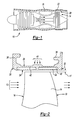
- Figure 1 is a schematic view of a turbine engine including a blade outer air seal according to this invention.
- Figure 2 is an enlarged sectional view of the turbine blade and blade outer air seal.
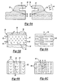
- Figure 3 is a partial sectional view of the blade outer air seal according to this invention.
- Figure 4 is a cross-sectional view of the blade outer air seal according to this invention.
- Figure 5A is a cross-sectional view of an axial edge cooling feature according to this invention.
- Figure 5B is a cross-sectional view of another axial edge cooling feature according to this invention.
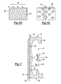
- Figure 6A is a schematic view of a pedestal according to this invention.
- Figure 6B is a schematic view of another pedestal according to this invention.
- Figure 6C is schematic view of another pedestal according to this invention.
- Figure 6D is a schematic view of another pedestal according to this invention.
- Figure 6E is a schematic view of another pedestal according to this invention.
- Figure 7 is a sectional side view of a sealing segment of this invention.
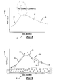
- Figure 8 is a graph illustrating a relationship between heat input and axial distance from a leading edge.
- Figure 9 is a graph illustrating a relationship between heat input and cooling capacity at an axial distance from the leading edge.
- Referring to Figures 1 and 2, a
turbine engine assembly 10 is partially and schematically shown and includes aturbine blade 14 for transforming energy from a hotcombustion gas flow 12 into mechanical energy. Theturbine blade 14 is an airfoil having a leadingedge 16 and atrailing edge 18.Gas flow 12 is directed toward theturbine blade 14 by anexhaust liner assembly 15 as is known. Theturbine blade 14 includes a tip edge 19 that is spaced apart from an outer air seal assembly 20. The outer air seal assembly 20 is spaced apart a desired clearance 17 to minimizegas flow 12 between the blade tip edge 19 and the outer air seal assembly 20. The outer air seal assembly 20 includes a plurality of outerair seal segments 22. - Referring to Figure 2 the outer
air seal segment 22 includes ahot side 24 that is exposed to thegas flow 12, and aback side 28 that is exposed to a supply ofcooling air flow 44. The outerair seal segment 22 includes a leadingedge 30, atrailing edge 32 and two axial edges 34 (Figure 3) transverse to the leading andtrailing edges seal segment 22 is mounted to a fixed structure of theengine assembly 10 by way of afront support leg 36 and arear support leg 38. Atrailing edge cavity 40 and a leadingedge cavity 42 are disposed within theseal segment 22 between thehot side 24 and theback side 28. Coolingair flow 44 is introduced on theback side 28 of theseal segment 22 and enters each of thecavities hot side 24. - Referring to Figures 3 and 4, the
cavities cooling air flow 44 through a plurality ofinlet openings 46. Theinlet openings 46 are disposed transverse to thegas flow 12. Theinlet openings 46 alternate thecavity divider 56 provides for the division of cooling air between theleading edge cavity 42 and the trailingedge cavity 40. Thedivider 56 is structured such thatadjacent inlet openings 46 supply cooling air todifferent cavities - Cooling
air flow 44 entering thecavities outlets 50 at theleading edge 30 and a plurality ofoutlets 52 along the trailingedge 32. Coolingair flow 44 also enters the cavities through a plurality ofre-supply openings 48. There-supply openings 48 introduceadditional cooling air 44 to local areas of thecavities - The
seal segment 22 also includesaxial cavities axial edges 34. Theaxial cavities cooling air flow 44 to theaxial edges 34 to preventhot gas 12 from seeping betweenadjacent seal segments 22. Theaxial cavities dividers 57 to isolate coolingair flow 44 from the other cavities. Theaxial cavities re-supply opening 48 in communication with only that cavity. Figure 4 illustratesaxial cavities axial edges 34 and on the leadingedge 30 and the trailingedge 32. This provides for control of heat build up and absorption at theaxial edges 34 separate from that provided by the leading edge and trailingedge cavities - Referring to Figure 5A another axial edge cooling configuration includes a
groove 61 for accepting a seal (not shown). Apassage 59 communicates coolingair 44 directly to the interface betweenadjacent seal segments 22. This provides for the cooling of theaxial edge 34 and prevents intrusion ofhot gases 12 betweenadjacent seal segments 22. - Referring to Figure 5B another axial edge cooling configuration includes
additional outlets 63 in communication with one of the leading edge or trailingedge cavities air flow 44 provides the desired cooling of the axial edges of eachseal segment 22. - Referring to Figures 3 and 4, the leading edge, trailing edge and
axial cavities air flow 44 to increase heat absorption capacity and to increase the surface area capable of transferring heat from thehot side 24. Thecavities top surface 58 and a bottom surface 60. The bottom surface 60 is shown and includes the plurality ofpedestals 62. - The
pedestals 62 extend between thetop surface 58 and the bottom surface 60 to form a honeycomb structure that creates a tortuous path for the coolingair flow 44. Thepedestals 62 are cylindrical structures that disrupt the laminar flow of the coolingair flow 44. Disruption of the coolingair flow 44 creates desirable turbulent flow from theinlets 46 to theoutlets pedestals 62 also provides an increase in heat absorption capacity. The combination of increased turbulent flow and increased surface area increases the efficiency of the cooling features allowing less cooling air flow to be utilized to provide the desired cooling of theseal segment 22. - Referring to Figures 6A-6E, although a
cylindrical pedestal 62 is illustrated as populating thecavities rectangular pedestals 80 that are placed to provide and create a tortuous path for coolingair flow 44. Figure 6B illustrates a plurality of chevron shapedpedestals 82 arranged betweenwalls 83 to create the desired turbulence in the coolingair flow 44. Figure 6C includes rectangular shapedpedestals 84 positioned in an alternating arrangement to disruptair flow 44. Figure 6D illustrates a plurality of wavywalled pedestals 86 that create a tortuous path for cooling air flow. Figure 6E includes a plurality of oval shaped pedestals 88 that are alternately arranged to provide the desired tortuous path for the coolingair flow 44. The examples illustrated are not exhaustive and other shapes an configuration are within the contemplation of this invention to accomplish application specific cooling properties. - The
seal segment 22 is constructed utilizing a lost core molding operation where a core is provided having a desired configuration that would provide the desired cavity structure. The core is over-molded with a material forming the segment. The material may include metal, composite structures or, as a worker versed in the art knows, ceramic structures. The core is then removed from theseal segment 22 to provide the desired internal configuration of thecavities seal segment 22 are within the contemplation of this invention. - Referring to Figure 7, the
seal segment 22 is shown in cross-section and includes the plurality ofinlets 46 in a generally midpoint location between theleading edge 50 and the trailingedge 52. The midway location of the plurality ofinlets 46 corresponds with a region of greatest heating of theseal segment 22. Thehot side 24 of theseal segment 22 is hottest at the location that is offset slightly toward the leadingedge 50 from a location substantially midway between theleading edge 50 and the trailingedge 52. The location of the plurality ofinlets 46 corresponds with the greatest heated region on the surface of thehot side 24. From the inlet coolingair flow 44 is divided between theleading edge cavity 42 and the trailingedge cavity 40. The coolingair flow 44 flows toward theoutlets edges re-supply openings 48 add additionalcooling air flow 44 to a location spaced apart from the plurality ofinlets 46. - Referring to Figures 8 and 9, to provide the desired cooling of the
seal segment 22 and thereby a constant temperature of thehot side 24, the amount of heat removed by the coolingair flow 44 is substantially the same as the amount of heat input from thegas flow 12. Figure 8 is a graph including aline 64 that shows a relationship between heat input into theseal segment 22 relative to anaxial location 68 from the leadingedge 30. Heat input is greatest at a point slightly forward of a midway point of theseal segment 22. The quantity of heat steadily declines toward the leading edge, as shown byarrow 72 and toward the trailing edges, shown byarrow 70. Coolingair flow 44 initially entering thecavities seal segment 22. As the coolingair flow 44 moves away from theinlets 46, it increases temperature, and therefore has a reduced heat absorption capacity. - Referring to Figure 9, a graph is shown that relates heat absorption capacity of the cooing
air 44 at an axial distance with the heat input into theseal segment 22. Figure 9 illustrates the relationship betweenheat input 76 anaxial distance 77 from the leading edge.Lines 70 represent heat input into theseal segment 22 at the axial location.Lines 74 represent the heat absorption capacity of the coolingair flow 44 at the axial location. As appreciated at the inlet location the heat absorption capacity is greatest and corresponds with the maximum amount of heat input into theseal segment 22.Heat input 70 and heat absorption capacity decreases with axial distance away from the hot points. Theseal segment 22 includes heat absorption capacity that is matched to the heat input to maintain a desired temperature of thehot side 24. - Further, a small peak indicated at 78 represents a location of the
re-supply openings 48. There-supply openings 48 provide additionalcooling air flow 44 required to maintain and balance a relationship between cooling capacity and heat input into theseal segment 22. Theleading edge cavity 42 and the trailingedge cavity 40 provide a cooling potential that matches the external heat loads on theseal segment 22. The pedestal geometries in each of thecavities hot side 24 for any axial location. The specific location is determined according to application specific requirements to provide the desired cooling capacity in local areas of the seal segment. - The
seal segment 22 of this invention provides improved heat removal properties by directing incomingcooling air flow 44 to the region of greatest heating and by generating turbulent flow over increased cavity surface area provided by the plurality ofpedestals 62. The resultingseal segment 22 provides improved cooling without a corresponding increase in cooling air flow requirements. - Although a preferred embodiment of this invention has been disclosed, a worker of ordinary skill in this art would recognize that certain modifications would come within the scope of this invention. For that reason, the following claims should be studied to determine the true scope and content of this invention.
Claims (20)
- A blade outer air seal assembly (20) for a turbine engine comprising:a cavity (40, 42) including a top surface (58) and a bottom surface (60), said top surface (58) comprising a side opposite a back side (28), and said bottom surface (60) comprising a side opposite a hot side (24) exposed to combustion gases; anda plurality of pedestals (62) extending between said top surface (58) and said bottom surface (60) for creating turbulent cooling air flow through said cavity (40, 42).
- The assembly as recited in claim 1, wherein said blade outer seal assembly includes a leading edge (30), a trailing edge (32), two axial edges (34) and a plurality of inlet openings (46) in said back side (28) for providing cooling air flow into said cavity (40, 42).
- The assembly as recited in claim 2, wherein said plurality of inlet openings (46) are arranged in a row substantially parallel with said leading edge (30) and said trailing edge (32).
- The assembly as recited in claim 2 or 3, wherein said plurality of inlet openings (46) are arranged substantially midway between said leading edge (30) and said trailing edge (32).
- The assembly as recited in claim 2, 3 or 4, wherein said cavity (40, 42) includes a divider (56) for separating cooling air flow from said inlet openings (46) such that a portion of said cooling air flow flows toward said leading edge (30) and another portion flows toward said trailing edge (32).
- The assembly as recited in claim 5, wherein said cavity (40, 42) comprises a leading edge cavity (42) and a trailing edge (40) cavity isolated from each other by said divider (56), wherein a cooling capacity of said cooling air flow corresponds to heat input such that said seal assembly maintains a desired surface temperature.
- The assembly as recited in claim 5 or 6, wherein said plurality of pedestals (62) comprises a first plurality of pedestals (62) arranged between said divider (56) and said leading edge (30) and a second plurality of pedestals (62) arranged between said divider (56) and said trailing edge (32).
- The assembly as recited in claim 7, including a third and a fourth plurality of pedestals (62) disposed along respective axial edges (34).
- The assembly as recited in claim 8, wherein each of said third and fourth plurality of pedestals (52) are isolated from any other of said pluralities of pede stals (62) by an axial divider (57).
- The assembly as recited in any of claims 2 to 9, including a plurality of outlets (50, 52) disposed at said leading edge (30) and said trailing edge (32) for exhausting cooling air flow into the flow of combustion gases.
- The assembly as recited in any preceding claim, wherein each of said plurality of pedestals comprises a cylindrical member (62).
- The assembly as recited in any of claims 1 to 10, wherein each of said plurality of pedestals comprises a chevron shaped structure (82).
- The assembly as recited in any of claims 1 to 10, wherein each of said plurality of pedestals comprises a rectangular structure (80, 84).
- The assembly as recited in any of claims 1 to 10, wherein each of said plurality of pedestals comprises an oval-shaped structure (88).
- The assembly as recited in any preceding claim, wherein said plurality of pedestals comprise a tortuous path for cooling air flow.
- A turbine blade shroud assembly for a turbine engine comprising:a plurality of interfitting blade outer air seal segments (22), each of said plurality of interfitting blade outer air seal assemblies comprising a cavity (40, 42) including a top surface (58) and a bottom surface (60), said top surface (58) comprising a side opposite a back side (28), and said bottom surface (60) comprising a side opposite a hot side (24) exposed to combustion gases, and a plurality of pedestals (62) extending between said top surface (58) and said bottom surface (60) for creating turbulent cooling air flow through said cavity (40, 42).
- The assembly as recited in claim 16, including an axial joint between adjacent ones of said plurality of interfitting blade outer air seal segments (22).
- The assembly as recited in claim 16 or 17, wherein each of said plurality of outer air seal segments (22) include a leading edge (30), a trailing edge (32), axial edges (34) and a plurality of inlet openings (46) disposed along said back side (28) between said leading and trailing edges (30, 32).
- The assembly as recited in claim 18, wherein said cavity (40, 42) comprises a leading edge cavity (42) and a trailing edge cavity (40) separated by a divider (56).
- The assembly as recited in claim 19, wherein said inlet openings (46) are disposed to inject cooling air flow at an axial location with a greatest heat generation.
Applications Claiming Priority (1)
| Application Number | Priority Date | Filing Date | Title |
|---|---|---|---|
| US11/025,172 US7306424B2 (en) | 2004-12-29 | 2004-12-29 | Blade outer seal with micro axial flow cooling system |
Publications (2)
| Publication Number | Publication Date |
|---|---|
| EP1676981A2 true EP1676981A2 (en) | 2006-07-05 |
| EP1676981A3 EP1676981A3 (en) | 2009-09-16 |
Family
ID=35781250
Family Applications (1)
| Application Number | Title | Priority Date | Filing Date |
|---|---|---|---|
| EP05258103A Withdrawn EP1676981A3 (en) | 2004-12-29 | 2005-12-29 | Coolable turbine shroud seal segment |
Country Status (5)
| Country | Link |
|---|---|
| US (1) | US7306424B2 (en) |
| EP (1) | EP1676981A3 (en) |
| JP (1) | JP2006189044A (en) |
| KR (1) | KR100664627B1 (en) |
| CN (1) | CN1796727A (en) |
Cited By (13)
| Publication number | Priority date | Publication date | Assignee | Title |
|---|---|---|---|---|
| EP1914390A2 (en) | 2006-10-12 | 2008-04-23 | United Technologies Corporation | Blade outer air seals |
| WO2010009997A1 (en) * | 2008-07-22 | 2010-01-28 | Alstom Technology Ltd. | Shroud seal segments arrangement in a gas turbine |
| US8246299B2 (en) | 2007-02-28 | 2012-08-21 | Rolls-Royce, Plc | Rotor seal segment |
| EP2562358A1 (en) * | 2010-04-20 | 2013-02-27 | Mitsubishi Heavy Industries, Ltd. | Split-ring cooling structure and gas turbine |
| EP2628905A3 (en) * | 2012-02-17 | 2014-06-04 | United Technologies Corporation | Turbomachine hot-section component protrusion, corresponding component and method of augmentIng a surface area |
| EP2479385A3 (en) * | 2011-01-25 | 2014-07-30 | United Technologies Corporation | Blade outer air seal assembly and support |
| US8814507B1 (en) | 2013-05-28 | 2014-08-26 | Siemens Energy, Inc. | Cooling system for three hook ring segment |
| EP2855857A4 (en) * | 2012-06-04 | 2016-06-08 | United Technologies Corp | Blade outer air seal with cored passages |
| EP3121387A1 (en) * | 2015-07-24 | 2017-01-25 | Rolls-Royce Corporation | A gas turbine engine with a seal segment |
| EP3181825A1 (en) * | 2015-12-16 | 2017-06-21 | General Electric Company | Shroud segment with hook-shaped cooling channels |
| EP3599347A1 (en) * | 2018-07-23 | 2020-01-29 | United Technologies Corporation | Attachment block for blade outer air seal providing impingement cooling |
| EP3748133A1 (en) * | 2019-06-07 | 2020-12-09 | Raytheon Technologies Corporation | Fatigue resistant blade outer air seal |
| US10968772B2 (en) * | 2018-07-23 | 2021-04-06 | Raytheon Technologies Corporation | Attachment block for blade outer air seal providing convection cooling |
Families Citing this family (112)
| Publication number | Priority date | Publication date | Assignee | Title |
|---|---|---|---|---|
| US7721433B2 (en) * | 2005-03-28 | 2010-05-25 | United Technologies Corporation | Blade outer seal assembly |
| US7513040B2 (en) * | 2005-08-31 | 2009-04-07 | United Technologies Corporation | Manufacturable and inspectable cooling microcircuits for blade-outer-air-seals |
| US7621719B2 (en) * | 2005-09-30 | 2009-11-24 | United Technologies Corporation | Multiple cooling schemes for turbine blade outer air seal |
| US9133715B2 (en) * | 2006-09-20 | 2015-09-15 | United Technologies Corporation | Structural members in a pedestal array |
| FR2907841B1 (en) * | 2006-10-30 | 2011-04-15 | Snecma | TURBINE MACHINE RING SECTOR |
| US7686577B2 (en) * | 2006-11-02 | 2010-03-30 | Siemens Energy, Inc. | Stacked laminate fiber wrapped segment |
| US7665953B2 (en) * | 2006-11-30 | 2010-02-23 | General Electric Company | Methods and system for recuperated cooling of integral turbine nozzle and shroud assemblies |
| US7604453B2 (en) * | 2006-11-30 | 2009-10-20 | General Electric Company | Methods and system for recuperated circumferential cooling of integral turbine nozzle and shroud assemblies |
| US7740442B2 (en) * | 2006-11-30 | 2010-06-22 | General Electric Company | Methods and system for cooling integral turbine nozzle and shroud assemblies |
| US8123466B2 (en) * | 2007-03-01 | 2012-02-28 | United Technologies Corporation | Blade outer air seal |
| US8061979B1 (en) * | 2007-10-19 | 2011-11-22 | Florida Turbine Technologies, Inc. | Turbine BOAS with edge cooling |
| US8366383B2 (en) * | 2007-11-13 | 2013-02-05 | United Technologies Corporation | Air sealing element |
| US8206092B2 (en) * | 2007-12-05 | 2012-06-26 | United Technologies Corp. | Gas turbine engines and related systems involving blade outer air seals |
| US8177492B2 (en) * | 2008-03-04 | 2012-05-15 | United Technologies Corporation | Passage obstruction for improved inlet coolant filling |
| US8118546B2 (en) * | 2008-08-20 | 2012-02-21 | Siemens Energy, Inc. | Grid ceramic matrix composite structure for gas turbine shroud ring segment |
| US8317461B2 (en) * | 2008-08-27 | 2012-11-27 | United Technologies Corporation | Gas turbine engine component having dual flow passage cooling chamber formed by single core |
| US8167559B2 (en) * | 2009-03-03 | 2012-05-01 | Siemens Energy, Inc. | Turbine vane for a gas turbine engine having serpentine cooling channels within the outer wall |
| US8740551B2 (en) * | 2009-08-18 | 2014-06-03 | Pratt & Whitney Canada Corp. | Blade outer air seal cooling |
| DE102009054006A1 (en) * | 2009-11-19 | 2011-05-26 | Rolls-Royce Deutschland Ltd & Co Kg | Turbine housing for gas turbine of turbo engine, particularly aircraft, is subdivided in multiple segments at circumference, where segments are extended in circumferential direction and in axial direction |
| US8529201B2 (en) * | 2009-12-17 | 2013-09-10 | United Technologies Corporation | Blade outer air seal formed of stacked panels |
| US9085053B2 (en) * | 2009-12-22 | 2015-07-21 | United Technologies Corporation | In-situ turbine blade tip repair |
| JP4634528B1 (en) | 2010-01-26 | 2011-02-23 | 三菱重工業株式会社 | Split ring cooling structure and gas turbine |
| US8556575B2 (en) * | 2010-03-26 | 2013-10-15 | United Technologies Corporation | Blade outer seal for a gas turbine engine |
| US8388300B1 (en) * | 2010-07-21 | 2013-03-05 | Florida Turbine Technologies, Inc. | Turbine ring segment |
| US8613590B2 (en) | 2010-07-27 | 2013-12-24 | United Technologies Corporation | Blade outer air seal and repair method |
| US20120128472A1 (en) * | 2010-11-23 | 2012-05-24 | General Electric Company | Turbomachine nozzle segment having an integrated diaphragm |
| US8475121B1 (en) * | 2011-01-17 | 2013-07-02 | Florida Turbine Technologies, Inc. | Ring segment for industrial gas turbine |
| US9062558B2 (en) | 2011-07-15 | 2015-06-23 | United Technologies Corporation | Blade outer air seal having partial coating |
| US9080458B2 (en) | 2011-08-23 | 2015-07-14 | United Technologies Corporation | Blade outer air seal with multi impingement plate assembly |
| ITCO20110036A1 (en) * | 2011-09-07 | 2013-03-08 | Nuovo Pignone Spa | GASKET FOR A ROTATING MACHINE |
| US9017012B2 (en) * | 2011-10-26 | 2015-04-28 | Siemens Energy, Inc. | Ring segment with cooling fluid supply trench |
| US8858159B2 (en) * | 2011-10-28 | 2014-10-14 | United Technologies Corporation | Gas turbine engine component having wavy cooling channels with pedestals |
| US9127549B2 (en) * | 2012-04-26 | 2015-09-08 | General Electric Company | Turbine shroud cooling assembly for a gas turbine system |
| US9885368B2 (en) | 2012-05-24 | 2018-02-06 | Carrier Corporation | Stall margin enhancement of axial fan with rotating shroud |
| US20130315719A1 (en) * | 2012-05-25 | 2013-11-28 | General Electric Company | Turbine Shroud Cooling Assembly for a Gas Turbine System |
| US20140064969A1 (en) * | 2012-08-29 | 2014-03-06 | Dmitriy A. Romanov | Blade outer air seal |
| US9790801B2 (en) * | 2012-12-27 | 2017-10-17 | United Technologies Corporation | Gas turbine engine component having suction side cutback opening |
| WO2014133706A1 (en) * | 2013-02-26 | 2014-09-04 | United Technologies Corporation | Edge treatment for gas turbine engine component |
| US10006367B2 (en) * | 2013-03-15 | 2018-06-26 | United Technologies Corporation | Self-opening cooling passages for a gas turbine engine |
| US20160194979A1 (en) * | 2013-09-06 | 2016-07-07 | United Technologies Corporation | Canted boas intersegment geometry |
| WO2015042262A1 (en) * | 2013-09-18 | 2015-03-26 | United Technologies Corporation | Tortuous cooling passageway for engine component |
| US10309255B2 (en) | 2013-12-19 | 2019-06-04 | United Technologies Corporation | Blade outer air seal cooling passage |
| KR102105631B1 (en) * | 2013-12-19 | 2020-04-28 | 엘지디스플레이 주식회사 | Display device |
| KR101509384B1 (en) * | 2014-01-16 | 2015-04-07 | 두산중공업 주식회사 | Sealing installation for blade tip of gas turbine |
| EP3096912A4 (en) | 2014-01-22 | 2017-02-01 | United Technologies Corporation | Method for additively constructing internal channels |
| JP6466647B2 (en) * | 2014-03-27 | 2019-02-06 | 三菱日立パワーシステムズ株式会社 | Gas turbine split ring cooling structure and gas turbine having the same |
| US10690055B2 (en) * | 2014-05-29 | 2020-06-23 | General Electric Company | Engine components with impingement cooling features |
| US10329934B2 (en) | 2014-12-15 | 2019-06-25 | United Technologies Corporation | Reversible flow blade outer air seal |
| EP3048262A1 (en) * | 2015-01-20 | 2016-07-27 | Alstom Technology Ltd | Wall for a hot gas channel in a gas turbine |
| US11808210B2 (en) | 2015-02-12 | 2023-11-07 | Rtx Corporation | Intercooled cooling air with heat exchanger packaging |
| US10371055B2 (en) | 2015-02-12 | 2019-08-06 | United Technologies Corporation | Intercooled cooling air using cooling compressor as starter |
| US10731560B2 (en) | 2015-02-12 | 2020-08-04 | Raytheon Technologies Corporation | Intercooled cooling air |
| US10221715B2 (en) | 2015-03-03 | 2019-03-05 | Rolls-Royce North American Technologies Inc. | Turbine shroud with axially separated pressure compartments |
| US9863265B2 (en) * | 2015-04-15 | 2018-01-09 | General Electric Company | Shroud assembly and shroud for gas turbine engine |
| US10830148B2 (en) | 2015-04-24 | 2020-11-10 | Raytheon Technologies Corporation | Intercooled cooling air with dual pass heat exchanger |
| US10221862B2 (en) | 2015-04-24 | 2019-03-05 | United Technologies Corporation | Intercooled cooling air tapped from plural locations |
| US10480419B2 (en) | 2015-04-24 | 2019-11-19 | United Technologies Corporation | Intercooled cooling air with plural heat exchangers |
| US10100739B2 (en) | 2015-05-18 | 2018-10-16 | United Technologies Corporation | Cooled cooling air system for a gas turbine engine |
| US10196919B2 (en) | 2015-06-29 | 2019-02-05 | Rolls-Royce North American Technologies Inc. | Turbine shroud segment with load distribution springs |
| US10047624B2 (en) | 2015-06-29 | 2018-08-14 | Rolls-Royce North American Technologies Inc. | Turbine shroud segment with flange-facing perimeter seal |
| US10385718B2 (en) | 2015-06-29 | 2019-08-20 | Rolls-Royce North American Technologies, Inc. | Turbine shroud segment with side perimeter seal |
| US10094234B2 (en) | 2015-06-29 | 2018-10-09 | Rolls-Royce North America Technologies Inc. | Turbine shroud segment with buffer air seal system |
| US10184352B2 (en) | 2015-06-29 | 2019-01-22 | Rolls-Royce North American Technologies Inc. | Turbine shroud segment with integrated cooling air distribution system |
| US10794288B2 (en) | 2015-07-07 | 2020-10-06 | Raytheon Technologies Corporation | Cooled cooling air system for a turbofan engine |
| US10107128B2 (en) | 2015-08-20 | 2018-10-23 | United Technologies Corporation | Cooling channels for gas turbine engine component |
| US10100654B2 (en) | 2015-11-24 | 2018-10-16 | Rolls-Royce North American Technologies Inc. | Impingement tubes for CMC seal segment cooling |
| US10443508B2 (en) | 2015-12-14 | 2019-10-15 | United Technologies Corporation | Intercooled cooling air with auxiliary compressor control |
| US10309252B2 (en) | 2015-12-16 | 2019-06-04 | General Electric Company | System and method for cooling turbine shroud trailing edge |
| US10132194B2 (en) | 2015-12-16 | 2018-11-20 | Rolls-Royce North American Technologies Inc. | Seal segment low pressure cooling protection system |
| US10378380B2 (en) | 2015-12-16 | 2019-08-13 | General Electric Company | Segmented micro-channel for improved flow |
| CN108884716B (en) * | 2016-03-31 | 2021-04-23 | 西门子股份公司 | Turbine airfoil with internal cooling passage having flow splitter feature |
| US10458268B2 (en) | 2016-04-13 | 2019-10-29 | Rolls-Royce North American Technologies Inc. | Turbine shroud with sealed box segments |
| US11193386B2 (en) | 2016-05-18 | 2021-12-07 | Raytheon Technologies Corporation | Shaped cooling passages for turbine blade outer air seal |
| US10344611B2 (en) * | 2016-05-19 | 2019-07-09 | United Technologies Corporation | Cooled hot section components for a gas turbine engine |
| US10669940B2 (en) | 2016-09-19 | 2020-06-02 | Raytheon Technologies Corporation | Gas turbine engine with intercooled cooling air and turbine drive |
| US10550768B2 (en) | 2016-11-08 | 2020-02-04 | United Technologies Corporation | Intercooled cooled cooling integrated air cycle machine |
| US10794290B2 (en) | 2016-11-08 | 2020-10-06 | Raytheon Technologies Corporation | Intercooled cooled cooling integrated air cycle machine |
| US10961911B2 (en) | 2017-01-17 | 2021-03-30 | Raytheon Technologies Corporation | Injection cooled cooling air system for a gas turbine engine |
| US10995673B2 (en) | 2017-01-19 | 2021-05-04 | Raytheon Technologies Corporation | Gas turbine engine with intercooled cooling air and dual towershaft accessory gearbox |
| EP3351735B1 (en) * | 2017-01-23 | 2023-10-18 | MTU Aero Engines AG | Turbomachine housing element |
| US20180223681A1 (en) * | 2017-02-09 | 2018-08-09 | General Electric Company | Turbine engine shroud with near wall cooling |
| US10655495B2 (en) * | 2017-02-24 | 2020-05-19 | General Electric Company | Spline for a turbine engine |
| US10577964B2 (en) | 2017-03-31 | 2020-03-03 | United Technologies Corporation | Cooled cooling air for blade air seal through outer chamber |
| US10711640B2 (en) | 2017-04-11 | 2020-07-14 | Raytheon Technologies Corporation | Cooled cooling air to blade outer air seal passing through a static vane |
| US10677084B2 (en) | 2017-06-16 | 2020-06-09 | Honeywell International Inc. | Turbine tip shroud assembly with plural shroud segments having inter-segment seal arrangement |
| US10900378B2 (en) | 2017-06-16 | 2021-01-26 | Honeywell International Inc. | Turbine tip shroud assembly with plural shroud segments having internal cooling passages |
| KR101983469B1 (en) * | 2017-10-20 | 2019-09-10 | 두산중공업 주식회사 | Ring segment of turbine blade and turbine and gas turbine comprising the same |
| US10502093B2 (en) * | 2017-12-13 | 2019-12-10 | Pratt & Whitney Canada Corp. | Turbine shroud cooling |
| US10533454B2 (en) | 2017-12-13 | 2020-01-14 | Pratt & Whitney Canada Corp. | Turbine shroud cooling |
| US11274569B2 (en) | 2017-12-13 | 2022-03-15 | Pratt & Whitney Canada Corp. | Turbine shroud cooling |
| US10570773B2 (en) | 2017-12-13 | 2020-02-25 | Pratt & Whitney Canada Corp. | Turbine shroud cooling |
| US10738703B2 (en) | 2018-03-22 | 2020-08-11 | Raytheon Technologies Corporation | Intercooled cooling air with combined features |
| US10689997B2 (en) * | 2018-04-17 | 2020-06-23 | Raytheon Technologies Corporation | Seal assembly for gas turbine engine |
| US10830145B2 (en) | 2018-04-19 | 2020-11-10 | Raytheon Technologies Corporation | Intercooled cooling air fleet management system |
| US10808619B2 (en) | 2018-04-19 | 2020-10-20 | Raytheon Technologies Corporation | Intercooled cooling air with advanced cooling system |
| US10989070B2 (en) * | 2018-05-31 | 2021-04-27 | General Electric Company | Shroud for gas turbine engine |
| US10718233B2 (en) | 2018-06-19 | 2020-07-21 | Raytheon Technologies Corporation | Intercooled cooling air with low temperature bearing compartment air |
| US10989068B2 (en) * | 2018-07-19 | 2021-04-27 | General Electric Company | Turbine shroud including plurality of cooling passages |
| US11255268B2 (en) | 2018-07-31 | 2022-02-22 | Raytheon Technologies Corporation | Intercooled cooling air with selective pressure dump |
| CN109538305A (en) * | 2018-11-23 | 2019-03-29 | 东方电气集团东方汽轮机有限公司 | A kind of gas turbine segmentation ring cooling structure |
| JP6726776B2 (en) * | 2019-01-10 | 2020-07-22 | 三菱日立パワーシステムズ株式会社 | Cooling structure for split ring of gas turbine and gas turbine having the same |
| US10927693B2 (en) | 2019-01-31 | 2021-02-23 | General Electric Company | Unitary body turbine shroud for turbine systems |
| US10822986B2 (en) | 2019-01-31 | 2020-11-03 | General Electric Company | Unitary body turbine shrouds including internal cooling passages |
| US10830050B2 (en) | 2019-01-31 | 2020-11-10 | General Electric Company | Unitary body turbine shrouds including structural breakdown and collapsible features |
| JP6636668B1 (en) | 2019-03-29 | 2020-01-29 | 三菱重工業株式会社 | High-temperature component, method for manufacturing high-temperature component, and method for adjusting flow rate |
| US11073036B2 (en) * | 2019-06-03 | 2021-07-27 | Raytheon Technologies Corporation | Boas flow directing arrangement |
| US11365645B2 (en) * | 2020-10-07 | 2022-06-21 | Pratt & Whitney Canada Corp. | Turbine shroud cooling |
| KR102510535B1 (en) * | 2021-02-23 | 2023-03-15 | 두산에너빌리티 주식회사 | Ring segment and turbo-machine comprising the same |
| KR102510537B1 (en) * | 2021-02-24 | 2023-03-15 | 두산에너빌리티 주식회사 | Ring segment and turbo-machine comprising the same |
| US11454137B1 (en) * | 2021-05-14 | 2022-09-27 | Doosan Heavy Industries & Construction Co., Ltd | Gas turbine inner shroud with array of protuberances |
| US11814974B2 (en) * | 2021-07-29 | 2023-11-14 | Solar Turbines Incorporated | Internally cooled turbine tip shroud component |
| US11815022B2 (en) * | 2021-08-06 | 2023-11-14 | Rtx Corporation | Platform serpentine re-supply |
Citations (1)
| Publication number | Priority date | Publication date | Assignee | Title |
|---|---|---|---|---|
| US5649806A (en) | 1993-11-22 | 1997-07-22 | United Technologies Corporation | Enhanced film cooling slot for turbine blade outer air seals |
Family Cites Families (13)
| Publication number | Priority date | Publication date | Assignee | Title |
|---|---|---|---|---|
| US4573866A (en) * | 1983-05-02 | 1986-03-04 | United Technologies Corporation | Sealed shroud for rotating body |
| US5375973A (en) * | 1992-12-23 | 1994-12-27 | United Technologies Corporation | Turbine blade outer air seal with optimized cooling |
| US5486090A (en) * | 1994-03-30 | 1996-01-23 | United Technologies Corporation | Turbine shroud segment with serpentine cooling channels |
| US5584651A (en) * | 1994-10-31 | 1996-12-17 | General Electric Company | Cooled shroud |
| JP3302370B2 (en) | 1995-04-11 | 2002-07-15 | ユナイテッド・テクノロジーズ・コーポレーション | External air seal for turbine blades with thin film cooling slots |
| JP3462695B2 (en) | 1997-03-12 | 2003-11-05 | 三菱重工業株式会社 | Gas turbine blade seal plate |
| US6146091A (en) * | 1998-03-03 | 2000-11-14 | Mitsubishi Heavy Industries, Ltd. | Gas turbine cooling structure |
| US6139257A (en) * | 1998-03-23 | 2000-10-31 | General Electric Company | Shroud cooling assembly for gas turbine engine |
| US6368054B1 (en) * | 1999-12-14 | 2002-04-09 | Pratt & Whitney Canada Corp. | Split ring for tip clearance control |
| EP1124039A1 (en) * | 2000-02-09 | 2001-08-16 | General Electric Company | Impingement cooling apparatus for a gas turbine shroud system |
| US6779597B2 (en) * | 2002-01-16 | 2004-08-24 | General Electric Company | Multiple impingement cooled structure |
| US7033138B2 (en) * | 2002-09-06 | 2006-04-25 | Mitsubishi Heavy Industries, Ltd. | Ring segment of gas turbine |
| ES2289256T3 (en) * | 2003-02-19 | 2008-02-01 | Alstom Technology Ltd | SEALING SYSTEM, PARTICULARLY FOR GAS TURBINE ALABES SEGMENTS. |
-
2004
- 2004-12-29 US US11/025,172 patent/US7306424B2/en active Active
-
2005
- 2005-12-14 JP JP2005359702A patent/JP2006189044A/en active Pending
- 2005-12-15 KR KR1020050123549A patent/KR100664627B1/en not_active IP Right Cessation
- 2005-12-28 CN CNA200510137767XA patent/CN1796727A/en active Pending
- 2005-12-29 EP EP05258103A patent/EP1676981A3/en not_active Withdrawn
Patent Citations (1)
| Publication number | Priority date | Publication date | Assignee | Title |
|---|---|---|---|---|
| US5649806A (en) | 1993-11-22 | 1997-07-22 | United Technologies Corporation | Enhanced film cooling slot for turbine blade outer air seals |
Cited By (24)
| Publication number | Priority date | Publication date | Assignee | Title |
|---|---|---|---|---|
| EP1914390A3 (en) * | 2006-10-12 | 2011-05-18 | United Technologies Corporation | Blade outer air seals |
| EP1914390A2 (en) | 2006-10-12 | 2008-04-23 | United Technologies Corporation | Blade outer air seals |
| US8246299B2 (en) | 2007-02-28 | 2012-08-21 | Rolls-Royce, Plc | Rotor seal segment |
| KR101584974B1 (en) | 2008-07-22 | 2016-01-13 | 알스톰 테크놀러지 리미티드 | Shroud seal segments arrangement in a gas turbine |
| WO2010009997A1 (en) * | 2008-07-22 | 2010-01-28 | Alstom Technology Ltd. | Shroud seal segments arrangement in a gas turbine |
| CH699232A1 (en) * | 2008-07-22 | 2010-01-29 | Alstom Technology Ltd | Gas turbine. |
| US8353663B2 (en) | 2008-07-22 | 2013-01-15 | Alstom Technology Ltd | Shroud seal segments arrangement in a gas turbine |
| EP2562358A1 (en) * | 2010-04-20 | 2013-02-27 | Mitsubishi Heavy Industries, Ltd. | Split-ring cooling structure and gas turbine |
| EP2562358A4 (en) * | 2010-04-20 | 2014-07-23 | Mitsubishi Heavy Ind Ltd | Split-ring cooling structure and gas turbine |
| US10077680B2 (en) | 2011-01-25 | 2018-09-18 | United Technologies Corporation | Blade outer air seal assembly and support |
| EP2479385A3 (en) * | 2011-01-25 | 2014-07-30 | United Technologies Corporation | Blade outer air seal assembly and support |
| US9255491B2 (en) | 2012-02-17 | 2016-02-09 | United Technologies Corporation | Surface area augmentation of hot-section turbomachine component |
| EP2628905A3 (en) * | 2012-02-17 | 2014-06-04 | United Technologies Corporation | Turbomachine hot-section component protrusion, corresponding component and method of augmentIng a surface area |
| EP2855857A4 (en) * | 2012-06-04 | 2016-06-08 | United Technologies Corp | Blade outer air seal with cored passages |
| US10196917B2 (en) | 2012-06-04 | 2019-02-05 | United Technologies Corporation | Blade outer air seal with cored passages |
| US8814507B1 (en) | 2013-05-28 | 2014-08-26 | Siemens Energy, Inc. | Cooling system for three hook ring segment |
| EP3121387A1 (en) * | 2015-07-24 | 2017-01-25 | Rolls-Royce Corporation | A gas turbine engine with a seal segment |
| US10641120B2 (en) | 2015-07-24 | 2020-05-05 | Rolls-Royce Corporation | Seal segment for a gas turbine engine |
| EP3181825A1 (en) * | 2015-12-16 | 2017-06-21 | General Electric Company | Shroud segment with hook-shaped cooling channels |
| EP3599347A1 (en) * | 2018-07-23 | 2020-01-29 | United Technologies Corporation | Attachment block for blade outer air seal providing impingement cooling |
| US10961866B2 (en) | 2018-07-23 | 2021-03-30 | Raytheon Technologies Corporation | Attachment block for blade outer air seal providing impingement cooling |
| US10968772B2 (en) * | 2018-07-23 | 2021-04-06 | Raytheon Technologies Corporation | Attachment block for blade outer air seal providing convection cooling |
| EP3748133A1 (en) * | 2019-06-07 | 2020-12-09 | Raytheon Technologies Corporation | Fatigue resistant blade outer air seal |
| US10961862B2 (en) | 2019-06-07 | 2021-03-30 | Raytheon Technologies Corporation | Fatigue resistant blade outer air seal |
Also Published As
| Publication number | Publication date |
|---|---|
| CN1796727A (en) | 2006-07-05 |
| US7306424B2 (en) | 2007-12-11 |
| KR100664627B1 (en) | 2007-01-04 |
| US20060140753A1 (en) | 2006-06-29 |
| KR20060076203A (en) | 2006-07-04 |
| JP2006189044A (en) | 2006-07-20 |
| EP1676981A3 (en) | 2009-09-16 |
Similar Documents
| Publication | Publication Date | Title |
|---|---|---|
| US7306424B2 (en) | Blade outer seal with micro axial flow cooling system | |
| US10502072B2 (en) | Compartmentalization of cooling air flow in a structure comprising a CMC component | |
| US6554563B2 (en) | Tangential flow baffle | |
| US8757974B2 (en) | Cooling circuit flow path for a turbine section airfoil | |
| US9011077B2 (en) | Cooled airfoil in a turbine engine | |
| EP2713011B1 (en) | Gas turbine engine components with blade tip cooling | |
| US7303376B2 (en) | Turbine airfoil with outer wall cooling system and inner mid-chord hot gas receiving cavity | |
| EP2204537B1 (en) | Turbine vane for gas turbine engine | |
| US8096772B2 (en) | Turbine vane for a gas turbine engine having serpentine cooling channels within the inner endwall | |
| US7416390B2 (en) | Turbine blade leading edge cooling system | |
| US7534089B2 (en) | Turbine airfoil with near wall multi-serpentine cooling channels | |
| US8118553B2 (en) | Turbine airfoil cooling system with dual serpentine cooling chambers | |
| EP2965010B1 (en) | Dual-wall impingement, convection, effusion combustor tile | |
| EP2610435B1 (en) | Turbine Rotor Blade Platform Cooling | |
| US11268392B2 (en) | Turbine vane assembly incorporating ceramic matrix composite materials and cooling | |
| EP3597865A1 (en) | Turbine vane assembly with ceramic matrix composite components | |
| US10370978B2 (en) | Turbine blade | |
| US10605170B2 (en) | Engine component with film cooling | |
| EP2634370B1 (en) | Turbine bucket with a core cavity having a contoured turn | |
| CA2944429A1 (en) | Turbine blade | |
| CN108779679B (en) | Cooled turbine blade | |
| US20170328212A1 (en) | Engine component wall with a cooling circuit | |
| EP3650639A1 (en) | Shield for a turbine engine airfoil | |
| EP2920426B1 (en) | Turbine blade with cooling arrangement |
Legal Events
| Date | Code | Title | Description |
|---|---|---|---|
| PUAI | Public reference made under article 153(3) epc to a published international application that has entered the european phase |
Free format text: ORIGINAL CODE: 0009012 |
|
| AK | Designated contracting states |
Kind code of ref document: A2 Designated state(s): AT BE BG CH CY CZ DE DK EE ES FI FR GB GR HU IE IS IT LI LT LU LV MC NL PL PT RO SE SI SK TR |
|
| AX | Request for extension of the european patent |
Extension state: AL BA HR MK YU |
|
| PUAL | Search report despatched |
Free format text: ORIGINAL CODE: 0009013 |
|
| AK | Designated contracting states |
Kind code of ref document: A3 Designated state(s): AT BE BG CH CY CZ DE DK EE ES FI FR GB GR HU IE IS IT LI LT LU LV MC NL PL PT RO SE SI SK TR |
|
| AX | Request for extension of the european patent |
Extension state: AL BA HR MK YU |
|
| 17P | Request for examination filed |
Effective date: 20091126 |
|
| 17Q | First examination report despatched |
Effective date: 20100115 |
|
| AKX | Designation fees paid |
Designated state(s): DE GB |
|
| GRAP | Despatch of communication of intention to grant a patent |
Free format text: ORIGINAL CODE: EPIDOSNIGR1 |
|
| INTG | Intention to grant announced |
Effective date: 20130719 |
|
| STAA | Information on the status of an ep patent application or granted ep patent |
Free format text: STATUS: THE APPLICATION IS DEEMED TO BE WITHDRAWN |
|
| 18D | Application deemed to be withdrawn |
Effective date: 20131130 |