EP1695225B1 - Addresses assignment for adaptor interfaces - Google Patents
Addresses assignment for adaptor interfaces Download PDFInfo
- Publication number
- EP1695225B1 EP1695225B1 EP04812611A EP04812611A EP1695225B1 EP 1695225 B1 EP1695225 B1 EP 1695225B1 EP 04812611 A EP04812611 A EP 04812611A EP 04812611 A EP04812611 A EP 04812611A EP 1695225 B1 EP1695225 B1 EP 1695225B1
- Authority
- EP
- European Patent Office
- Prior art keywords
- local
- remote
- interfaces
- address
- port
- Prior art date
- Legal status (The legal status is an assumption and is not a legal conclusion. Google has not performed a legal analysis and makes no representation as to the accuracy of the status listed.)
- Not-in-force
Links
Images


Classifications
-
- H—ELECTRICITY
- H04—ELECTRIC COMMUNICATION TECHNIQUE
- H04L—TRANSMISSION OF DIGITAL INFORMATION, e.g. TELEGRAPHIC COMMUNICATION
- H04L61/00—Network arrangements, protocols or services for addressing or naming
- H04L61/50—Address allocation
- H04L61/5038—Address allocation for local use, e.g. in LAN or USB networks, or in a controller area network [CAN]
-
- H—ELECTRICITY
- H04—ELECTRIC COMMUNICATION TECHNIQUE
- H04L—TRANSMISSION OF DIGITAL INFORMATION, e.g. TELEGRAPHIC COMMUNICATION
- H04L9/00—Cryptographic mechanisms or cryptographic arrangements for secret or secure communications; Network security protocols
- H04L9/40—Network security protocols
-
- H—ELECTRICITY
- H04—ELECTRIC COMMUNICATION TECHNIQUE
- H04L—TRANSMISSION OF DIGITAL INFORMATION, e.g. TELEGRAPHIC COMMUNICATION
- H04L61/00—Network arrangements, protocols or services for addressing or naming
-
- H—ELECTRICITY
- H04—ELECTRIC COMMUNICATION TECHNIQUE
- H04L—TRANSMISSION OF DIGITAL INFORMATION, e.g. TELEGRAPHIC COMMUNICATION
- H04L69/00—Network arrangements, protocols or services independent of the application payload and not provided for in the other groups of this subclass
- H04L69/30—Definitions, standards or architectural aspects of layered protocol stacks
- H04L69/32—Architecture of open systems interconnection [OSI] 7-layer type protocol stacks, e.g. the interfaces between the data link level and the physical level
- H04L69/322—Intralayer communication protocols among peer entities or protocol data unit [PDU] definitions
- H04L69/326—Intralayer communication protocols among peer entities or protocol data unit [PDU] definitions in the transport layer [OSI layer 4]
-
- H—ELECTRICITY
- H04—ELECTRIC COMMUNICATION TECHNIQUE
- H04L—TRANSMISSION OF DIGITAL INFORMATION, e.g. TELEGRAPHIC COMMUNICATION
- H04L69/00—Network arrangements, protocols or services independent of the application payload and not provided for in the other groups of this subclass
- H04L69/30—Definitions, standards or architectural aspects of layered protocol stacks
- H04L69/32—Architecture of open systems interconnection [OSI] 7-layer type protocol stacks, e.g. the interfaces between the data link level and the physical level
- H04L69/322—Intralayer communication protocols among peer entities or protocol data unit [PDU] definitions
- H04L69/329—Intralayer communication protocols among peer entities or protocol data unit [PDU] definitions in the application layer [OSI layer 7]
Definitions
- FIG. 3 illustrates an example of how devices 100 and 102 may interface, where the device 100 has eight PHYs 104a, 104b...104j linked to eight PHYs 106a, 106b...106j, respectively, at the device 104.
- the devices 100 and 102 may comprise a host, expander, storage device, server, etc., where the devices may implement the architecture described with respect to FIG. 2
- These devices 100 and 102 may have an initial address configuration for their PHYs, where the PHYs may share the same port address and be in the same domain.
- the initial address configuration for the PHYs in a device is based on user configuration selections.
- the device e.g., 100 ( FIG.3 )
- the device does not perform the identification sequence again and instead uses the domain identifier and SAS address to distinguish PHYs having the same address that are connected to different devices.
- external devices 182, 184, 186 may use the same SAS address to address the local PHYs.
- the described embodiments provide techniques for assigning PHYs or interfaces to ports when the interfaces receive different SAS addresses from the attached PHYs.
- the embodiment of FIG. 6 minimizes communication and coordination between the local and remote PHYs, because the initial address configuration is used for interfaces that receive different addresses from the attached device and the device internally distinguishes interfaces connected to different addresses by assigning the interfaces to different domains.
- the configuration is performed to form ports having a maximum possible width, i.e., maximum number of PHYs/connections. Maximizing the number of PHYs in a port maximizes the throughput for a port. Further, maximizing PHYs maximizes the load balancing opportunities. Yet further, maximizing the number of PHYs and connections at a port increases the number of alternate paths to the port, which minimizes I/O latency. Still further, maximizing the number of PHYs at a port provides redundant connections to allow continued operations should one or more PHYs fail.
- the described embodiments may be implemented as a method, apparatus or article of manufacture using programming and/or engineering techniques to produce software, firmware, hardware, or any combination thereof.
- article of manufacture and “circuitry” as used herein refers to a state machine, code or logic implemented in hardware logic (e.g., an integrated circuit chip, Programmable Gate Array (PGA), Application Specific Integrated Circuit (ASIC), etc.) or a computer readable medium, such as magnetic storage medium (e.g., hard disk drives, floppy disks,, tape, etc.), optical storage (CD-ROMs, optical disks, etc.), volatile and non-volatile memory devices (e.g., EEPROMs, ROMs, PROMS, RAMs, DRAMs, SRAMs, firmware, programmable logic, etc.).
- Code in the computer readable medium is accessed and executed by a processor.
- the circuitry may include the medium including the code or logic as well as the processor that executes the code loaded from the medium.
- the code in which preferred embodiments are implemented may further be accessible through a transmission media or from a file server over a network.
- the article of manufacture in which the code is implemented may comprise a transmission media, such as a network transmission line, wireless transmission media, signals propagating through space, radio waves, infrared signals, etc.
- the "article of manufacture” may comprise the medium in which the code is embodied.
- the “article of manufacture” may comprise a combination of hardware and software components in which the code is embodied, processed, and executed.
- a physical interface was represented by a PHY, providing an interface between the physical connection and other layers within the adaptor.
- the interface representing a physical connection may be implemented using constructs other than a PHY.
- Described embodiments utilize the SAS architecture.
- the described techniques for assigning physical connections to ports may apply to additional storage interfaces.
- transmissions are received at a device from a remote device over a connection.
- the transmitted and received information processed by the transport protocol layer or device driver may be received from a separate process executing in the same computer in which the device driver and transport protocol driver execute.
- the device driver and network adaptor embodiments may be included in a computer system including a storage controller, such as a SCSI, Redundant Array of Independent Disk (RAID), etc., controller, that manages access to a non-volatile storage device, such as a magnetic disk drive, tape media, optical disk, etc.
- a storage controller such as a SCSI, Redundant Array of Independent Disk (RAID), etc.
- RAID Redundant Array of Independent Disk
- the network adaptor embodiments may be included in a system that does not include a storage controller, such as certain hubs and switches.
- the storage interfaces supported by the adaptors comprised SATA and SAS. In additional embodiments, other storage interfaces may be supported. Additionally, the adaptor was described as supporting certain transport protocols, e.g. SSP, STP, and SMP. In further implementations, the adaptor may support additional transport protocols used for transmissions with the supported storage interfaces.
- the supported storage interfaces may transmit data at the same link speeds or at different, non-overlapping link speeds.
- the physical interfaces may have different physical configurations, i.e., the arrangement and number of pins and other physical interconnectors, when the different supported storage interconnect architectures use different physical configurations.
- FIGs. 4 and 6 show certain events occurring in a certain order. In alternative embodiments, certain operations may be performed in a different order, modified or removed. Moreover, operations may be added to the above described operations and still conform to the described embodiments. Further, operations described herein may occur sequentially or certain operations may be processed in parallel. Yet further, operations may be performed by a single processing unit or by distributed processing units.
- the adaptors 12a, 12b may be implemented in a network card, such as a Peripheral Component Interconnect (PCI) card or some other I/O card, or on integrated circuit components mounted on a system motherboard or backplane.
- PCI Peripheral Component Interconnect
Abstract
Description
- The embodiments relate to addresses assignment for adaptor interfaces.
- An adaptor or multi-channel protocol controller enables a device coupled to the adaptor to communicate with one or more connected end devices over a physical cable or line according to a storage interconnect architecture, also known as a hardware interface, where a storage interconnect architecture defines a standard way to communicate and recognize such communications, such as Serial Attached Small Computer System Interface (SCSI) (SAS), Serial Advanced Technology Attachment (SATA), etc. These storage interconnect architectures allow a device to maintain one or more connections, such as direct point-to-point connections with end devices or connections extending through one or more expanders. Devices may also interconnect through a switch, an expander, a Fibre Channel arbitrated loop, fabric, etc. In the SAS/SATA architecture, a SAS port is comprised of one or more SAS PHYs, where each SAS PHY interfaces a physical layer, i.e., the physical interface or connection, and a SAS link layer having multiple protocol link layer. Communications from the SAS PHYs in a port is processed by the transport layers for that port. There is one transport layer for each SAS port to interface with each type of application layer supported by the port. A "PHY" as defined in the SAS protocol is a device object that is used to interface to other devices and a physical interface. Further details on the SAS architecture for devices and expanders is described in the technology specification "Information Technology - Serial Attached SCSI (SAS)", reference no. ISO/IEC 14776-150:200x and ANSI INCITS.***:200x PHY layer (July 9, 2003), published by ANSI; details on the Fibre Channel architecture are described in the technology specification "Fibre Channel Framing and Signaling Interface", document no. ISO/IEC AWI 14165-25; details on the SATA architecture are described in the technology specification "Serial ATA: High Speed Serialized AT Attachment" Rev. 1.0A (Jan. 2003).
- [0001] Within an adaptor, the PHY layer may include the parallel-to-serial converter to perform the serial to parallel conversion of data, so that parallel data is transmitted to layers above the PHY layer, and serial data is transmitted from the PHY layer through the physical interface to the PHY layer of a receiving device. In the SAS specification, there is one set of link layers for each SAS PHY layer, so that effectively each link layer protocol engine is coupled to a parallel-to-serial converter in the PHY layer. The physical interfaces for PHYs on different devices may connect through a cable or through a path etched on the circuit board to connect through a circuit board path.
- [0002] As mentioned, a port contains one or more PHYs. Ports in a device are associated with physical PHYs based on the configuration that occurs during an identification sequence. A port is assigned one or more PHYs within a device for those PHYs within that device that are configured to use the same SAS address within a SAS domain during the identification sequence, where PHYs on a device having the same SAS address in one port connects to PHYs on a remote device that also use the same SAS address within a SAS domain. A wide port has multiple interfaces, or PHYs and a narrow port has only one PHY. A wide link comprises the set of physical links that connect the PHYs of a wide port to the corresponding PHYs in the corresponding remote wide port and a narrow link is the physical link that attaches a narrow port to a corresponding remote narrow port. Further details on the SAS architecture is described in the technology specification "Information Technology-Serial Attached SCSI (SAS)", reference no. ISO/IEC 14776-150:200x and ANSI INCITS.***:200x PHY layer (Jul. 9, 2003), published by ANSI.
EP-A-1 363 429 describes a network device, e.g., router, comprising a switch fabric coupled to a plurality of blades where each blade may comprise one or more network processors coupled to one or more physical ports. The physical ports may be connected to another one or more network devices.
"American National Standard for Information Technology-Serial Attached SCSI (SAS)", American National Standard, xx, xx, vol. 376-2003, 11 November 2003 (2003-11-11), XP009049765 " specifies the functional requirements for the Serial Attached SCSI (SAS) physical interconnect, which is compatible with the Serial ATA physical interconnect. It also specifies three transport protocols, one to transport SCSI commands, another to transport Serial ATA commands to multiple SATA devices, and a third to support interface management. This standard is intended to be used in conjunction with SCSI and ATA command set standards.
US-B1-6 553 005 describes a method for routing a packet received in a packet router to egress ports. The method comprises the steps of selecting a logical interface having multiple physical ports as a destination for the packet, processing any one or more addresses or labels of the packet and other packets received by a common function, producing thereby results unique to the packets in which the addresses and labels processed differ, mapping the physical ports at the destination to the unique results produced by processing the addresses or labels of packets and routing the data packet, according to the mapping.
US-A-6 061 349 discloses a system and method for implementing multiple IP addresses on multiple ports by mapping virtual addresses and ports to physical ones. The system keeps track of a virtual IP address and port to which client is attempting to connect and the corresponding physical IP address and port assigned to the virtual IP address and port and translates a destination port from a user, to a port on which the server is running the daemon for the user specified port. - Referring now to the drawings in which like reference numbers represent corresponding parts throughout:
-
FIGS. 1 and2 illustrate a system and adaptor in accordance with embodiments; -
FIGS. 3 ,5a ,5b , and7 illustrate how devices may connect in accordance with embodiments; and -
FIGS. 4 and6 illustrate operations to perform an identification sequence between connected devices in accordance with embodiments. - In the following description, reference is made to the accompanying drawings which form a part hereof and which illustrate several embodiments. It is understood that other embodiments may be utilized and structural and operational changes may be made.
-
FIG. 1 illustrates a computing environment in which embodiments may be implemented. A host system 2 includes one or more central processing units (CPU) 4 (only one is shown), avolatile memory 6, non-volatile storage 8, an operating system 10, andadaptors application program 16 further executes inmemory 6 and is capable of transmitting and receiving transmissions via one of theadaptors memory 6 may be swapped into storage 8 as part of memory management operations. - The operating system 10 may load a
device driver adaptor 12 to enable communication with a device communicating using the same supported storage interface and also load a bus interface 24, such as a Peripheral Component Interconnect (PCI) interface, to enable communication with abus 26. Further details of PCI interface are described in the publication "PCI Local Bus, Rev. 2.3", published by the PCI-SIG. The operating system 10 may loaddevice drivers adaptors adaptors FIG. 1 , the operating system 10 loads threedevice drivers device drivers adaptors -
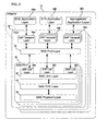
FIG. 2 illustrates an embodiment of anadaptor 12, which may comprise theadaptors SAS link layer 36 having one or more protocol link layers.FIG. 2 shows three protocol link layers, including a Serial SCSI Protocol (SSP)link layer 38a to process SSP frames, a Serial Tunneling Protocol. (STP)layer 38b, a Serial Management Protocol (SMP)layer 38c, which in turn interface through port layer 32 with their respective transport layers, a SSP transport layer 40a, aSTP transport layer 40b, and anSMP transport layer 40c. The layers may be implemented as program components executed from memory and/or implemented in hardware. - Each
PHY 34 for port 30 further includes a SAS PHY layer 42 and aphysical layer 44. Thephysical layer 44 comprises the physical interface, including the transmitter and receiver circuitry, paths, and connectors. As shown, thephysical layer 44 is coupled to the PHY layer 42, where the PHY layer 42 provides for an encoding, scheme, such as 8b10b to translate bits, and a clocking mechanism. The PHY layer 42a, 42b...42n may include a serial-to-parallel converter to perform the serial-to-parallel conversion and a phased lock loop (PLL) to track the incoming data and provide the data clock of the incoming data to the serial-to-parallel converter to use when performing the conversion. Data is received, at theadaptor 12 in a serial format, and is converted at the SAS PHYS layer 42a, 42b...42n to the parallel format for transmission within theadaptor 12. The SAS PHY layer 42 further provides for error detection, bit shift and amplitude reduction, and the out-of-band (OOB) signaling to establish an operational link with another SAS PHY in another device, speed negotiation with the PHY in the external device transmitting data toadaptor 12, etc. - In the embodiment of
FIG. 2 , there is oneprotocol transport layer application layer adaptor 12 or host system 2 and provides network services to the end users. For instance, the SSP transport layer 40a interfaces with aSCSI application layer 48a, theSTP transport layer 40b interfaces with an Advanced Technology Attachment (ATA)application layer 48b, and theSMP transport layer 40c interfaces with amanagement application layer 48c. Further details on the operations of the physical layer, PHY layer, link layer, port layer, transport layer, and application layer and components implementing such layers described herein are found in the technology specification "Information Technology - Serial Attached SCSI (SAS)". Further details of the ATA technology are described in the publication "Information Technology -AT Attachment with Packet Interface - 6 (ATA/ATAPI-6)", reference no. ANSI INCITS 361-2002 (September, 2002). - Each port 30 has a unique SAS address across
adaptors 12 and eachPHY 34 within the port has a unique identifier within theadaptor 12 for management functions and routing. Anadaptor 12 may further have one or more unique domain addresses, where different ports in anadaptor 12 can be organized into different domains or devices. The SAS address of a PHY may comprise the SAS address of the port to which the PHY is assigned and that port SAS address is used to identify and address the PHY to external devices in a SAS domain. -
FIG. 3 illustrates an example of howdevices device 100 has eightPHYs PHYs devices FIG. 2 Thesedevices -
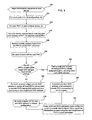
FIG. 4 illustrates operations implemented in a device implementing the architecture ofFIG. 2 , such asadaptor 12devices FIG. 4 may be programmed in the port layer 32 of theadaptor 12,devices device driver adaptor 12. Upon commencing (at block 150) the identification sequence after a reset or power-on sequence at a device, e.g., 100, a loop is performed atblock 152 through 170 for each port j provided in the initial or default configuration maintained at the device, e.g., 100. For each initial port j a loop is performed atblocks 154 through 160 for each PHY i assigned to port j in the initial configuration. Atblock 156, a device, e.g., 100, transmits identify address information including the SAS address of PHY i, which is the SAS address of port j, to the attached PHY, e.g., 106a, 106b... 106h inremote device 102. The PHY i further receives (at block 158) the identify address information from the PHY to which PHY i is attached.Device 100 may receive the identification information from theremote device 102 before transmitting identification information, or vice versa. Identification for a PHY is complete when a PHY has transmitted and received identification information. Further, if thedevice 100 does not receive identification information for the attached device PHY, then a timeout may occur where the entire link initialization process is restarted. Control then proceeds back to block 154 to transmit and receive the identify address information for the next PHY. - After all the PHYs, e.g., 104a, 104b...104h, have received the identify address information from the attached PHYs, e.g., 106a, 106b... 106h, a determination is made (at block 162) whether all the PHYs, e.g., 104a, 104b...104h, received the same SAS address from the PHYs to which they connect. If so, then a wide port is formed for port j including all the PHYs, e.g., 104a, 104b...104h, initially assigned to port j, so that all are configured to use the initial port j SAS address. The common SAS address of all the remote PHYs, e.g., 106a, 106b...106h, is then associated with the common port j SAS address of the local PHYs, e.g., 104a, 104b...104h, to use during operations. If (at block 162) the SAS addresses of the
remote PHYs block 166 or 168, control proceeds (at block 170) back to block 152 to consider any further ports in the initial configuration. After considering all ports in the initial configuration, if (at block 172) new ports and SAS addresses were configured, control proceeds back to block 150 to perform a second instance of the initialization process using the new assignment of PHYs to port addresses. - The local and remote PHYs comprise local and remote interfaces at the local and remote devices, respectively. An interface is a physical or logical component that is connected to another interface on the same or a different device. The term interface may include interfaces other than PHY interfaces. A wide port comprises a port assigned multiple interfaces, where one or more interfaces may be assigned to a port. A local address, such as the local SAS address, comprises an address or identifier assigned to one or more interfaces and a remote address, such as the remote SAS address, comprises an address or identifier assigned to one or more interfaces in a remote device that connects to another interface, such as one of the local interfaces.
- With the operations of
FIG. 4 , the ports are configured to include the maximum number of PHYs in each new port, where the PHYs in each new port will connect to PHYs in the connected adaptor that have the same SAS address. Further, if the PHYs in an initial port configuration are not connected to PHYs having the same PHY address, then new ports are configured with new SAS addresses to provide new ports, so that the PHYs assigned to the new ports connect.to PHYs in the connected adaptors having the same SAS address. Further, after the reconfiguration of the ports, the identification sequence is performed again to perform configuration using the new port configuration. -
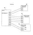
FIG. 5a illustrates an embodiment where the PHYs in thedevice 180 are configured to have one SAS address "x", which connect to PHYs in threedifferent devices FIG. 4 within a device having the configuration ofFIG. 5a results in the configuration shown inFIG. 5b , in which adaptor 180 is configured to use three SAS addresses XA, XB, and XC to communicate with the PHYS indevices -
FIG. 6 illustrates an alternative embodiment of operations to perform the identification sequence and establish port configurations.FIG. 6 includes many of the same operations ofFIG. 4 , with the following exceptions. After determining (at block 212) that the connected PHYs do not return the same address for a port j, instead of configuring new ports with different SAS addresses as done inFIG. 4 , atblock 218, for each received unique target SAS address k, a different domain is formed in thedevice 180 having a unique domain identifier. Each PHY is then internally identified using both the SAS address and the newly configured domain identifier. After the domain designation is made, the device, e.g., 100 (FIG.3 ), does not perform the identification sequence again and instead uses the domain identifier and SAS address to distinguish PHYs having the same address that are connected to different devices. However,external devices -
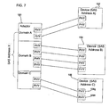
FIG. 7 illustrates an embodiment resulting from performing the operations ofFIG. 6 in a device having the configuration shown inFIG. 5a , in which the device, e.g., 100, is configured to use the same SAS address "X" for PHYs connected to different devices 252, 254, and 256, but where those PHYs connected to different addresses are configured in different domains A, B, C. Thus, the device 250 uses the combination of domain identifier and SAS address to distinguish its local PHYs. With the embodiment ofFIG. 6 , a second identification sequence is not performed, unlike the second identification sequence performed atblock 172 inFIG. 4 , because there is no alteration of the default port configuration. Instead, the same address "X" is used. Thus, theremote devices FIG. 7 ) use the same SAS address to address the different PHYs indevice 180 and thedevice 180 uses the domain addresses A, B, C in combination with the port SAS address "X" to distinguish the local PHYs, devices. - The described embodiments provide techniques for assigning PHYs or interfaces to ports when the interfaces receive different SAS addresses from the attached PHYs. The embodiment of
FIG. 6 minimizes communication and coordination between the local and remote PHYs, because the initial address configuration is used for interfaces that receive different addresses from the attached device and the device internally distinguishes interfaces connected to different addresses by assigning the interfaces to different domains. - In certain embodiments, the configuration is performed to form ports having a maximum possible width, i.e., maximum number of PHYs/connections. Maximizing the number of PHYs in a port maximizes the throughput for a port. Further, maximizing PHYs maximizes the load balancing opportunities. Yet further, maximizing the number of PHYs and connections at a port increases the number of alternate paths to the port, which minimizes I/O latency. Still further, maximizing the number of PHYs at a port provides redundant connections to allow continued operations should one or more PHYs fail.
- The described embodiments may be implemented as a method, apparatus or article of manufacture using programming and/or engineering techniques to produce software, firmware, hardware, or any combination thereof. The term "article of manufacture" and "circuitry" as used herein refers to a state machine, code or logic implemented in hardware logic (e.g., an integrated circuit chip, Programmable Gate Array (PGA), Application Specific Integrated Circuit (ASIC), etc.) or a computer readable medium, such as magnetic storage medium (e.g., hard disk drives, floppy disks,, tape, etc.), optical storage (CD-ROMs, optical disks, etc.), volatile and non-volatile memory devices (e.g., EEPROMs, ROMs, PROMS, RAMs, DRAMs, SRAMs, firmware, programmable logic, etc.). Code in the computer readable medium is accessed and executed by a processor. When the code or logic is executed by a processor, the circuitry may include the medium including the code or logic as well as the processor that executes the code loaded from the medium. The code in which preferred embodiments are implemented may further be accessible through a transmission media or from a file server over a network. In such cases, the article of manufacture in which the code is implemented may comprise a transmission media, such as a network transmission line, wireless transmission media, signals propagating through space, radio waves, infrared signals, etc. Thus, the "article of manufacture" may comprise the medium in which the code is embodied. Additionally, the "article of manufacture" may comprise a combination of hardware and software components in which the code is embodied, processed, and executed. Of course, those skilled in the art will recognize that many modifications may be made to this configuration, and that the article of manufacture may comprise any information bearing medium known in the art. Additionally, the devices, adaptors, etc., may be implemented in one or more integrated circuits on the adaptor or on the motherboard.
- In the described embodiments, a physical interface was represented by a PHY, providing an interface between the physical connection and other layers within the adaptor. In additional embodiments, the interface representing a physical connection may be implemented using constructs other than a PHY.
- Described embodiments utilize the SAS architecture. In alternative embodiments, the described techniques for assigning physical connections to ports may apply to additional storage interfaces.
- In the described embodiments, certain operations were described with respect to layers within the device/adaptor architectures. In alternative implementations, the functions described as performed by a certain layer may be performed in a different layer.
- In the described embodiments, transmissions are received at a device from a remote device over a connection. In alternative embodiments, the transmitted and received information processed by the transport protocol layer or device driver may be received from a separate process executing in the same computer in which the device driver and transport protocol driver execute.
- In certain embodiments, the device driver and network adaptor embodiments may be included in a computer system including a storage controller, such as a SCSI, Redundant Array of Independent Disk (RAID), etc., controller, that manages access to a non-volatile storage device, such as a magnetic disk drive, tape media, optical disk, etc. In alternative implementations, the network adaptor embodiments may be included in a system that does not include a storage controller, such as certain hubs and switches.
- In described embodiments, the storage interfaces supported by the adaptors comprised SATA and SAS. In additional embodiments, other storage interfaces may be supported. Additionally, the adaptor was described as supporting certain transport protocols, e.g. SSP, STP, and SMP. In further implementations, the adaptor may support additional transport protocols used for transmissions with the supported storage interfaces. The supported storage interfaces may transmit data at the same link speeds or at different, non-overlapping link speeds. Further, the physical interfaces may have different physical configurations, i.e., the arrangement and number of pins and other physical interconnectors, when the different supported storage interconnect architectures use different physical configurations.
- The illustrated operations of
FIGs. 4 and6 show certain events occurring in a certain order. In alternative embodiments, certain operations may be performed in a different order, modified or removed. Moreover, operations may be added to the above described operations and still conform to the described embodiments. Further, operations described herein may occur sequentially or certain operations may be processed in parallel. Yet further, operations may be performed by a single processing unit or by distributed processing units. - The
adaptors - The foregoing description of various embodiments has been presented for the purposes of illustration and description. Many modifications and variations are possible in light of the above teaching.
Claims (26)
- A method, comprising:maintaining an initial configuration by assigning one initial local port address to a port to which multiple local interfaces (104a-h) are assigned as part of the initial configuration;for each local interface, receiving a remote address of a remote interface (106a-h) on at least one remote device (102, 182, 184, 186) to which the local interface connects;using the initial local port address to identify the local interfaces assigned to the initial local port address in response to the local interfaces receiving a common remote address from the remote interfaces connected to the local interfaces assigned the initial local port address;generating at least one identifier in response to receiving multiple remote addresses from the remote interfaces (106a-h) connected to the local interfaces (104a-h) ; andassigning different identifiers to the local interfaces previously assigned the initial local port address in response to generating the at least one identifier.
- The method of claim 1, wherein each generated identifier comprises an additional port address, further comprising:configuring an additional port in the device for each generated additional port address; and assigning local interfaces (104a-h) to the ports, including the additional port and port having the initial local port address.
- The method of claim 2, wherein the local interfaces (104a-h) assigned to one port connect to remote interfaces (106a-h) having a same remote address.
- The method of claim 1, wherein the at least one received remote address is received as part of an identification sequence, further comprising:transmitting the initial local port address to the remote interfaces (106a-h) connected to the local interfaces (104a-h).
- The method of claim 4, wherein the identifiers assigned to the local interfaces (104a-h), including the at least one generated identifier, comprise local port addresses, further comprising: initiating an additional identification sequence in response to generating the at least one local port address; and transmitting the local port addresses identifying the local interfaces to the connected remote interfaces (106a-h) in response to the additional identification sequence.
- The method of claim 1, wherein the at least one remote device and (102, 182, 184, 186) a local device (100, 180) including the local interfaces (104a-h) implement the SAS architecture, wherein the local and remote addresses comprise SAS addresses, and wherein the local and remote interfaces (106a-h) comprise PHYs.
- The method of claim 1, wherein the remote interfaces (106a-h) having different remote addresses are on different remote devices (102, 182, 184, 186).
- The method of claim 1, wherein generating the at least one identifier comprises generating a different identifier for each received different remote address, wherein a combination of the identifiers and the initial local port address are used to identify the local interfaces (104a-h) assigned.
- The method of claim 10, wherein the plurality of identifiers comprise domains, wherein the local interfaces remain assigned to the port having the initial local port address.
- The method of claim 8, wherein the remote interfaces (106a-h) having different remote addresses are on different remote devices (102, 182, 184, 186), wherein the combination of each of the plurality of identifiers and the default local port address identify the local interfaces (104a-h) within a local device (100, 180) and wherein the initial local port address identifies the local interfaces within the remote devices.
- The method of claim 8, wherein the plurality of identifiers comprise domains, further comprising: for each received remote address, generating a different domain in a local device (100, 180) including the local interfaces (104a-h) connected to the remote interfaces (106a-h) having the remote addresses.
- The method of claim 11, wherein the generated domains include one domain in the initial configuration.
- A device (100, 102, 180, 182, 184, 186) in communication with a plurality of remote interfaces (106a-h) on at least one remote device (102, 182, 184, 186), comprising:a plurality of local interfaces (104a-h); an initial configuration assigning one initial local port address to a port to which multiple local interfaces are assigned as part of the initial configuration;circuitry capable of causing operations, the operations comprising:(i) for each local interface, receiving a remote address of one remote interface to which the local interface connects, and(ii) using the initial local port address to identify the local interfaces assigned to the initial local port address in response to the local interfaces receiving a common remote address form the remote interfaces connected to the local interfaces assigned the initial local port address;generating at least one identifier in response to receiving multiple remote addresses from the remote interfaces (106a-h) connected to the local interfaces (104a-h); andassigning different identifiers to the local interface previously assigned the initial local port address in response to generating the at least one identifier.
- The device (100, 102, 180, 182, 184, 186) of claim 13, wherein each generated identifier comprises an additional port address, and wherein the operations further comprise: configuring an additional port in the device for each generated additional port address; and
assigning local interfaces (104a-h) to the ports, including the additional port and port having the initial local port address. - The device (100, 102, 180, 182, 184, 186) of claim 14, wherein the local interfaces (104a-h) assigned to one port connect to remote interfaces (106a-h) having a same remote address.
- The device (100, 102, 180, 182, 184, 186) of claim 13, wherein the at least one received remote address is received as part of an identification sequence, wherein the operations further comprise: transmitting the initial local port address to the remote interfaces (106a-h) connected to the local interfaces (104a-h).
- The device (100, 102, 180, 182, 184, 186) of claim 13, wherein the identifiers assigned to the local interfaces (104a-h), including the at least one generated identifier, comprise local port addresses, wherein the operations further comprise: initiating an additional identification sequence in response to generating the at least one local port address; and transmitting the local port addresses identifying the local interfaces to the connected remote interfaces (106a-h) in response to the additional identification sequence.
- The device (100, 102, 180, 182, 184, 186) of claim 13, wherein the at least one remote device (102, 182, 184, 186) and the device implement the SAS architecture, wherein the local and remote addresses comprise SAS addresses, and wherein the local (104a-h) and remote interfaces comprise PHYs.
- The device (100, 102, 180, 182, 184, 186) of claim 13, wherein the remote interfaces (106a-h) having different I remote addresses are on different remote devices (102, 182, 184, 186).
- The device(100, 102, 180, 182, 184, 186) of claim 13, wherein generating the at least one identifier comprises generating a different identifier for each received different remote address, wherein a combination of the identifiers and the initial local port address are used to identify the local interfaces (104a-h) assigned.
- The device (100, 102, 180, 182, 184, 186) of claim 20, wherein the plurality of identifiers comprise domains, wherein the local interfaces remain assigned to the port having the initial local port address.
- The device (100, 102, 180, 182, 184, 186) of claim 20, wherein the remote interfaces (106a-h) having different remote addresses are on different remote devices (102, 182, 184, 186), wherein the combination of each of the plurality of identifiers and the default local port address identify the local interfaces within the local device (100, 180) and wherein the initial local port address identifies the local interfaces (104a-h)within the remote devices.
- The device (100, 102, 180, 182, 184, 186) of claim 20, wherein the plurality of identifiers comprise domains, wherein the operations further comprise: for each received remote address, generating a different domain in the local device including the local interfaces (104a-h) connected to the remote interfaces (106a-h) having the remote addresses.
- The device (100, 102, 180, 182, 184, 186) of claim 23, wherein the generated domains includes one domain in the initial configuration.
- A system comprising:a local device (100, 180) in accordance with claim 13 andat least one remote device (102, 182, 184, 186) in communication with the local device, the remote device having a plurality of remote interfaces (106a-h).
- An article of manufacture that stores instructions which, when executed in a local device (100, 180) having connected remote interfaces (106a-h) in at least one remote device (102, 182, 184, 186), cause operations to be performed in accordance with the method of any one of claims 1 to 12.
Applications Claiming Priority (2)
| Application Number | Priority Date | Filing Date | Title |
|---|---|---|---|
| US10/742,302 US7502865B2 (en) | 2003-12-18 | 2003-12-18 | Addresses assignment for adaptor interfaces |
| PCT/US2004/040138 WO2005064897A2 (en) | 2003-12-18 | 2004-12-01 | Addresses assignment for adaptor interfaces |
Publications (2)
| Publication Number | Publication Date |
|---|---|
| EP1695225A2 EP1695225A2 (en) | 2006-08-30 |
| EP1695225B1 true EP1695225B1 (en) | 2010-05-05 |
Family
ID=34678415
Family Applications (1)
| Application Number | Title | Priority Date | Filing Date |
|---|---|---|---|
| EP04812611A Not-in-force EP1695225B1 (en) | 2003-12-18 | 2004-12-01 | Addresses assignment for adaptor interfaces |
Country Status (7)
| Country | Link |
|---|---|
| US (2) | US7502865B2 (en) |
| EP (1) | EP1695225B1 (en) |
| CN (2) | CN101788971B (en) |
| AT (1) | ATE467186T1 (en) |
| DE (1) | DE602004027078D1 (en) |
| TW (1) | TWI283353B (en) |
| WO (1) | WO2005064897A2 (en) |
Families Citing this family (33)
| Publication number | Priority date | Publication date | Assignee | Title |
|---|---|---|---|---|
| US8526427B1 (en) | 2003-10-21 | 2013-09-03 | Cisco Technology, Inc. | Port-based loadsharing for a satellite switch |
| US7502865B2 (en) | 2003-12-18 | 2009-03-10 | Intel Corporation | Addresses assignment for adaptor interfaces |
| US7124234B2 (en) * | 2003-12-22 | 2006-10-17 | Intel Corporation | Managing transmissions between devices |
| US8990430B2 (en) | 2004-02-19 | 2015-03-24 | Cisco Technology, Inc. | Interface bundles in virtual network devices |
| US20050193178A1 (en) * | 2004-02-27 | 2005-09-01 | William Voorhees | Systems and methods for flexible extension of SAS expander ports |
| US8208370B1 (en) | 2004-03-31 | 2012-06-26 | Cisco Technology, Inc. | Method and system for fast link failover |
| US7889733B2 (en) * | 2004-04-28 | 2011-02-15 | Cisco Technology, Inc. | Intelligent adjunct network device |
| US7436836B2 (en) * | 2004-06-30 | 2008-10-14 | Cisco Technology, Inc. | Method and apparatus for detecting support for a protocol defining supplemental headers |
| US7808983B2 (en) | 2004-07-08 | 2010-10-05 | Cisco Technology, Inc. | Network device architecture for centralized packet processing |
| US8730976B2 (en) * | 2004-08-17 | 2014-05-20 | Cisco Technology, Inc. | System and method for preventing erroneous link aggregation due to component relocation |
| US8612632B2 (en) * | 2004-08-18 | 2013-12-17 | Lsi Corporation | Systems and methods for tag information validation in wide port SAS connections |
| US9495263B2 (en) * | 2004-12-21 | 2016-11-15 | Infortrend Technology, Inc. | Redundant SAS storage virtualization subsystem and system using the same, and method therefor |
| US8301810B2 (en) * | 2004-12-21 | 2012-10-30 | Infortrend Technology, Inc. | SAS storage virtualization controller, subsystem and system using the same, and method therefor |
| US7805543B2 (en) * | 2005-06-30 | 2010-09-28 | Intel Corporation | Hardware oriented host-side native command queuing tag management |
| US7970953B2 (en) * | 2005-06-30 | 2011-06-28 | Intel Corporation | Serial ATA port addressing |
| US8135869B2 (en) * | 2005-06-30 | 2012-03-13 | Intel Corporation | Task scheduling to devices with same connection address |
| US7953917B2 (en) * | 2005-06-30 | 2011-05-31 | Intel Corporation | Communications protocol expander |
| US7747788B2 (en) * | 2005-06-30 | 2010-06-29 | Intel Corporation | Hardware oriented target-side native command queuing tag management |
| US7676604B2 (en) * | 2005-11-22 | 2010-03-09 | Intel Corporation | Task context direct indexing in a protocol engine |
| US8447872B2 (en) * | 2006-11-01 | 2013-05-21 | Intel Corporation | Load balancing in a storage system |
| US8219719B1 (en) * | 2011-02-07 | 2012-07-10 | Lsi Corporation | SAS controller with persistent port configuration |
| WO2013095554A1 (en) | 2011-12-22 | 2013-06-27 | Intel Corporation | Processors, methods, systems, and instructions to generate sequences of consecutive integers in numerical order |
| US10223112B2 (en) | 2011-12-22 | 2019-03-05 | Intel Corporation | Processors, methods, systems, and instructions to generate sequences of integers in which integers in consecutive positions differ by a constant integer stride and where a smallest integer is offset from zero by an integer offset |
| CN104011644B (en) | 2011-12-22 | 2017-12-08 | 英特尔公司 | Processor, method, system and instruction for generation according to the sequence of the integer of the phase difference constant span of numerical order |
| WO2013095555A1 (en) * | 2011-12-22 | 2013-06-27 | Intel Corporation | Packed data rearrangement control indexes generation processors, methods, systems, and instructions |
| US8626974B2 (en) * | 2012-01-19 | 2014-01-07 | Lsi Corporation | Methods and systems for reduced signal path count for interconnect signals within a storage system expander |
| US8874821B2 (en) | 2012-04-17 | 2014-10-28 | Hewlett-Packard Development Company, L.P. | Determination of a zoned portion of a service delivery system |
| WO2015047296A1 (en) * | 2013-09-27 | 2015-04-02 | Hewlett-Packard Development Company, L.P. | Reusable zone |
| CN107888442B (en) * | 2016-09-30 | 2021-05-14 | 华为技术有限公司 | Port rate determining method and computer equipment |
| US20180165031A1 (en) * | 2016-12-09 | 2018-06-14 | Hewlett Packard Enterprise Development Lp | Port modes for storage drives |
| US10565041B2 (en) * | 2017-05-19 | 2020-02-18 | Western Digital Technologies, Inc. | Managing phys of a data storage target device |
| US10425333B2 (en) * | 2017-05-19 | 2019-09-24 | Western Digital Technologies, Inc. | Managing phys of a data storage target device |
| CN114185650B (en) * | 2021-12-14 | 2023-07-25 | 平安壹账通云科技(深圳)有限公司 | Method, system, equipment and storage medium for identifying SCSI equipment under Linux system |
Citations (1)
| Publication number | Priority date | Publication date | Assignee | Title |
|---|---|---|---|---|
| US6061349A (en) * | 1995-11-03 | 2000-05-09 | Cisco Technology, Inc. | System and method for implementing multiple IP addresses on multiple ports |
Family Cites Families (18)
| Publication number | Priority date | Publication date | Assignee | Title |
|---|---|---|---|---|
| US5706440A (en) * | 1995-08-23 | 1998-01-06 | International Business Machines Corporation | Method and system for determining hub topology of an ethernet LAN segment |
| US6038400A (en) * | 1995-09-27 | 2000-03-14 | Linear Technology Corporation | Self-configuring interface circuitry, including circuitry for identifying a protocol used to send signals to the interface circuitry, and circuitry for receiving the signals using the identified protocol |
| US6421711B1 (en) * | 1998-06-29 | 2002-07-16 | Emc Corporation | Virtual ports for data transferring of a data storage system |
| US6351375B1 (en) * | 1999-01-26 | 2002-02-26 | Dell Usa, L.P. | Dual-purpose backplane design for multiple types of hard disks |
| GB2354137B (en) | 1999-05-10 | 2002-05-15 | 3Com Corp | Supervising a network |
| US6553005B1 (en) * | 2000-07-26 | 2003-04-22 | Pluris, Inc. | Method and apparatus for load apportionment among physical interfaces in data routers |
| US6928478B1 (en) * | 2001-06-25 | 2005-08-09 | Network Appliance, Inc. | Method and apparatus for implementing a MAC address pool for assignment to a virtual interface aggregate |
| US6965559B2 (en) | 2001-10-19 | 2005-11-15 | Sun Microsystems, Inc. | Method, system, and program for discovering devices communicating through a switch |
| CN1314231C (en) * | 2001-12-19 | 2007-05-02 | 中兴通讯股份有限公司 | Self circulation method for program control exchanger |
| US6886051B2 (en) * | 2002-03-28 | 2005-04-26 | Seagate Technology Llc | Device discovery method and apparatus |
| US7280527B2 (en) * | 2002-05-13 | 2007-10-09 | International Business Machines Corporation | Logically grouping physical ports into logical interfaces to expand bandwidth |
| US7649880B2 (en) * | 2002-11-12 | 2010-01-19 | Mark Adams | Systems and methods for deriving storage area commands |
| US7376147B2 (en) * | 2003-12-18 | 2008-05-20 | Intel Corporation | Adaptor supporting different protocols |
| US7155546B2 (en) * | 2003-12-18 | 2006-12-26 | Intel Corporation | Multiple physical interfaces in a slot of a storage enclosure to support different storage interconnect architectures |
| US7502865B2 (en) | 2003-12-18 | 2009-03-10 | Intel Corporation | Addresses assignment for adaptor interfaces |
| US20050138154A1 (en) * | 2003-12-18 | 2005-06-23 | Intel Corporation | Enclosure management device |
| US20050138221A1 (en) * | 2003-12-23 | 2005-06-23 | Intel Corporation | Handling redundant paths among devices |
| US7738397B2 (en) * | 2004-02-19 | 2010-06-15 | Intel Corporation | Generating topology information identifying devices in a network topology |
-
2003
- 2003-12-18 US US10/742,302 patent/US7502865B2/en not_active Expired - Fee Related
-
2004
- 2004-12-01 DE DE602004027078T patent/DE602004027078D1/de active Active
- 2004-12-01 CN CN200910266849.2A patent/CN101788971B/en not_active Expired - Fee Related
- 2004-12-01 CN CN2004800368484A patent/CN1890655B/en not_active Expired - Fee Related
- 2004-12-01 WO PCT/US2004/040138 patent/WO2005064897A2/en not_active Application Discontinuation
- 2004-12-01 AT AT04812611T patent/ATE467186T1/en not_active IP Right Cessation
- 2004-12-01 EP EP04812611A patent/EP1695225B1/en not_active Not-in-force
- 2004-12-02 TW TW093137188A patent/TWI283353B/en not_active IP Right Cessation
-
2009
- 2009-01-09 US US12/351,777 patent/US8214525B2/en not_active Expired - Lifetime
Patent Citations (1)
| Publication number | Priority date | Publication date | Assignee | Title |
|---|---|---|---|---|
| US6061349A (en) * | 1995-11-03 | 2000-05-09 | Cisco Technology, Inc. | System and method for implementing multiple IP addresses on multiple ports |
Also Published As
| Publication number | Publication date |
|---|---|
| CN1890655A (en) | 2007-01-03 |
| EP1695225A2 (en) | 2006-08-30 |
| US8214525B2 (en) | 2012-07-03 |
| ATE467186T1 (en) | 2010-05-15 |
| US20050138202A1 (en) | 2005-06-23 |
| WO2005064897A3 (en) | 2006-01-05 |
| US7502865B2 (en) | 2009-03-10 |
| US20090119413A1 (en) | 2009-05-07 |
| DE602004027078D1 (en) | 2010-06-17 |
| TW200523749A (en) | 2005-07-16 |
| CN1890655B (en) | 2010-11-03 |
| CN101788971B (en) | 2014-03-12 |
| TWI283353B (en) | 2007-07-01 |
| WO2005064897A2 (en) | 2005-07-14 |
| CN101788971A (en) | 2010-07-28 |
Similar Documents
| Publication | Publication Date | Title |
|---|---|---|
| EP1695225B1 (en) | Addresses assignment for adaptor interfaces | |
| US7334075B2 (en) | Managing transmissions between devices | |
| EP1719289B1 (en) | Generating topology information identifying devices in a network topology | |
| US7376147B2 (en) | Adaptor supporting different protocols | |
| US7155546B2 (en) | Multiple physical interfaces in a slot of a storage enclosure to support different storage interconnect architectures | |
| US7921185B2 (en) | System and method for managing switch and information handling system SAS protocol communication | |
| EP1399829B1 (en) | End node partitioning using local identifiers | |
| US20050138154A1 (en) | Enclosure management device | |
| US6944152B1 (en) | Data storage access through switched fabric | |
| US20040225764A1 (en) | Method and apparatus for identifying multiple paths to SCSI device | |
| US8694723B2 (en) | Method and system for coupling serial attached SCSI (SAS) devices and internet small computer system internet (iSCSI) devices through single host bus adapter | |
| WO2006110844A2 (en) | Tunneling sata targets through fibre channel | |
| US20050138221A1 (en) | Handling redundant paths among devices | |
| US7647433B2 (en) | System and method for flexible multiple protocols | |
| US20070204103A1 (en) | Infiniband boot bridge with fibre channel target |
Legal Events
| Date | Code | Title | Description |
|---|---|---|---|
| PUAI | Public reference made under article 153(3) epc to a published international application that has entered the european phase |
Free format text: ORIGINAL CODE: 0009012 |
|
| 17P | Request for examination filed |
Effective date: 20060601 |
|
| AK | Designated contracting states |
Kind code of ref document: A2 Designated state(s): AT BE BG CH CY CZ DE DK EE ES FI FR GB GR HU IE IS IT LI LT LU MC NL PL PT RO SE SI SK TR |
|
| DAX | Request for extension of the european patent (deleted) | ||
| 17Q | First examination report despatched |
Effective date: 20070511 |
|
| R17C | First examination report despatched (corrected) |
Effective date: 20080505 |
|
| GRAP | Despatch of communication of intention to grant a patent |
Free format text: ORIGINAL CODE: EPIDOSNIGR1 |
|
| GRAS | Grant fee paid |
Free format text: ORIGINAL CODE: EPIDOSNIGR3 |
|
| GRAA | (expected) grant |
Free format text: ORIGINAL CODE: 0009210 |
|
| AK | Designated contracting states |
Kind code of ref document: B1 Designated state(s): AT BE BG CH CY CZ DE DK EE ES FI FR GB GR HU IE IS IT LI LT LU MC NL PL PT RO SE SI SK TR |
|
| REG | Reference to a national code |
Ref country code: GB Ref legal event code: FG4D |
|
| REG | Reference to a national code |
Ref country code: CH Ref legal event code: EP |
|
| REG | Reference to a national code |
Ref country code: IE Ref legal event code: FG4D |
|
| REF | Corresponds to: |
Ref document number: 602004027078 Country of ref document: DE Date of ref document: 20100617 Kind code of ref document: P |
|
| REG | Reference to a national code |
Ref country code: NL Ref legal event code: VDEP Effective date: 20100505 |
|
| LTIE | Lt: invalidation of european patent or patent extension |
Effective date: 20100505 |
|
| PG25 | Lapsed in a contracting state [announced via postgrant information from national office to epo] |
Ref country code: LT Free format text: LAPSE BECAUSE OF FAILURE TO SUBMIT A TRANSLATION OF THE DESCRIPTION OR TO PAY THE FEE WITHIN THE PRESCRIBED TIME-LIMIT Effective date: 20100505 Ref country code: NL Free format text: LAPSE BECAUSE OF FAILURE TO SUBMIT A TRANSLATION OF THE DESCRIPTION OR TO PAY THE FEE WITHIN THE PRESCRIBED TIME-LIMIT Effective date: 20100505 Ref country code: SE Free format text: LAPSE BECAUSE OF FAILURE TO SUBMIT A TRANSLATION OF THE DESCRIPTION OR TO PAY THE FEE WITHIN THE PRESCRIBED TIME-LIMIT Effective date: 20100505 Ref country code: ES Free format text: LAPSE BECAUSE OF FAILURE TO SUBMIT A TRANSLATION OF THE DESCRIPTION OR TO PAY THE FEE WITHIN THE PRESCRIBED TIME-LIMIT Effective date: 20100816 |
|
| PG25 | Lapsed in a contracting state [announced via postgrant information from national office to epo] |
Ref country code: SI Free format text: LAPSE BECAUSE OF FAILURE TO SUBMIT A TRANSLATION OF THE DESCRIPTION OR TO PAY THE FEE WITHIN THE PRESCRIBED TIME-LIMIT Effective date: 20100505 Ref country code: FI Free format text: LAPSE BECAUSE OF FAILURE TO SUBMIT A TRANSLATION OF THE DESCRIPTION OR TO PAY THE FEE WITHIN THE PRESCRIBED TIME-LIMIT Effective date: 20100505 Ref country code: AT Free format text: LAPSE BECAUSE OF FAILURE TO SUBMIT A TRANSLATION OF THE DESCRIPTION OR TO PAY THE FEE WITHIN THE PRESCRIBED TIME-LIMIT Effective date: 20100505 Ref country code: IS Free format text: LAPSE BECAUSE OF FAILURE TO SUBMIT A TRANSLATION OF THE DESCRIPTION OR TO PAY THE FEE WITHIN THE PRESCRIBED TIME-LIMIT Effective date: 20100905 |
|
| PG25 | Lapsed in a contracting state [announced via postgrant information from national office to epo] |
Ref country code: CY Free format text: LAPSE BECAUSE OF FAILURE TO SUBMIT A TRANSLATION OF THE DESCRIPTION OR TO PAY THE FEE WITHIN THE PRESCRIBED TIME-LIMIT Effective date: 20100505 Ref country code: PL Free format text: LAPSE BECAUSE OF FAILURE TO SUBMIT A TRANSLATION OF THE DESCRIPTION OR TO PAY THE FEE WITHIN THE PRESCRIBED TIME-LIMIT Effective date: 20100505 Ref country code: GR Free format text: LAPSE BECAUSE OF FAILURE TO SUBMIT A TRANSLATION OF THE DESCRIPTION OR TO PAY THE FEE WITHIN THE PRESCRIBED TIME-LIMIT Effective date: 20100806 |
|
| PG25 | Lapsed in a contracting state [announced via postgrant information from national office to epo] |
Ref country code: EE Free format text: LAPSE BECAUSE OF FAILURE TO SUBMIT A TRANSLATION OF THE DESCRIPTION OR TO PAY THE FEE WITHIN THE PRESCRIBED TIME-LIMIT Effective date: 20100505 Ref country code: DK Free format text: LAPSE BECAUSE OF FAILURE TO SUBMIT A TRANSLATION OF THE DESCRIPTION OR TO PAY THE FEE WITHIN THE PRESCRIBED TIME-LIMIT Effective date: 20100505 Ref country code: PT Free format text: LAPSE BECAUSE OF FAILURE TO SUBMIT A TRANSLATION OF THE DESCRIPTION OR TO PAY THE FEE WITHIN THE PRESCRIBED TIME-LIMIT Effective date: 20100906 |
|
| PG25 | Lapsed in a contracting state [announced via postgrant information from national office to epo] |
Ref country code: BE Free format text: LAPSE BECAUSE OF FAILURE TO SUBMIT A TRANSLATION OF THE DESCRIPTION OR TO PAY THE FEE WITHIN THE PRESCRIBED TIME-LIMIT Effective date: 20100505 Ref country code: SK Free format text: LAPSE BECAUSE OF FAILURE TO SUBMIT A TRANSLATION OF THE DESCRIPTION OR TO PAY THE FEE WITHIN THE PRESCRIBED TIME-LIMIT Effective date: 20100505 Ref country code: RO Free format text: LAPSE BECAUSE OF FAILURE TO SUBMIT A TRANSLATION OF THE DESCRIPTION OR TO PAY THE FEE WITHIN THE PRESCRIBED TIME-LIMIT Effective date: 20100505 Ref country code: CZ Free format text: LAPSE BECAUSE OF FAILURE TO SUBMIT A TRANSLATION OF THE DESCRIPTION OR TO PAY THE FEE WITHIN THE PRESCRIBED TIME-LIMIT Effective date: 20100505 |
|
| PLBE | No opposition filed within time limit |
Free format text: ORIGINAL CODE: 0009261 |
|
| STAA | Information on the status of an ep patent application or granted ep patent |
Free format text: STATUS: NO OPPOSITION FILED WITHIN TIME LIMIT |
|
| PG25 | Lapsed in a contracting state [announced via postgrant information from national office to epo] |
Ref country code: IT Free format text: LAPSE BECAUSE OF FAILURE TO SUBMIT A TRANSLATION OF THE DESCRIPTION OR TO PAY THE FEE WITHIN THE PRESCRIBED TIME-LIMIT Effective date: 20100505 |
|
| 26N | No opposition filed |
Effective date: 20110208 |
|
| REG | Reference to a national code |
Ref country code: DE Ref legal event code: R097 Ref document number: 602004027078 Country of ref document: DE Effective date: 20110207 |
|
| PG25 | Lapsed in a contracting state [announced via postgrant information from national office to epo] |
Ref country code: MC Free format text: LAPSE BECAUSE OF NON-PAYMENT OF DUE FEES Effective date: 20101231 |
|
| REG | Reference to a national code |
Ref country code: CH Ref legal event code: PL |
|
| REG | Reference to a national code |
Ref country code: FR Ref legal event code: ST Effective date: 20110831 |
|
| PG25 | Lapsed in a contracting state [announced via postgrant information from national office to epo] |
Ref country code: FR Free format text: LAPSE BECAUSE OF NON-PAYMENT OF DUE FEES Effective date: 20110103 Ref country code: IE Free format text: LAPSE BECAUSE OF NON-PAYMENT OF DUE FEES Effective date: 20101201 Ref country code: LI Free format text: LAPSE BECAUSE OF NON-PAYMENT OF DUE FEES Effective date: 20101231 Ref country code: CH Free format text: LAPSE BECAUSE OF NON-PAYMENT OF DUE FEES Effective date: 20101231 |
|
| PG25 | Lapsed in a contracting state [announced via postgrant information from national office to epo] |
Ref country code: LU Free format text: LAPSE BECAUSE OF NON-PAYMENT OF DUE FEES Effective date: 20101201 Ref country code: HU Free format text: LAPSE BECAUSE OF FAILURE TO SUBMIT A TRANSLATION OF THE DESCRIPTION OR TO PAY THE FEE WITHIN THE PRESCRIBED TIME-LIMIT Effective date: 20101106 Ref country code: BG Free format text: LAPSE BECAUSE OF FAILURE TO SUBMIT A TRANSLATION OF THE DESCRIPTION OR TO PAY THE FEE WITHIN THE PRESCRIBED TIME-LIMIT Effective date: 20100505 |
|
| PG25 | Lapsed in a contracting state [announced via postgrant information from national office to epo] |
Ref country code: TR Free format text: LAPSE BECAUSE OF FAILURE TO SUBMIT A TRANSLATION OF THE DESCRIPTION OR TO PAY THE FEE WITHIN THE PRESCRIBED TIME-LIMIT Effective date: 20100505 |
|
| PG25 | Lapsed in a contracting state [announced via postgrant information from national office to epo] |
Ref country code: BG Free format text: LAPSE BECAUSE OF FAILURE TO SUBMIT A TRANSLATION OF THE DESCRIPTION OR TO PAY THE FEE WITHIN THE PRESCRIBED TIME-LIMIT Effective date: 20100805 |
|
| PGFP | Annual fee paid to national office [announced via postgrant information from national office to epo] |
Ref country code: GB Payment date: 20171129 Year of fee payment: 14 |
|
| GBPC | Gb: european patent ceased through non-payment of renewal fee |
Effective date: 20181201 |
|
| PG25 | Lapsed in a contracting state [announced via postgrant information from national office to epo] |
Ref country code: GB Free format text: LAPSE BECAUSE OF NON-PAYMENT OF DUE FEES Effective date: 20181201 |
|
| PGFP | Annual fee paid to national office [announced via postgrant information from national office to epo] |
Ref country code: DE Payment date: 20191119 Year of fee payment: 16 |
|
| REG | Reference to a national code |
Ref country code: DE Ref legal event code: R119 Ref document number: 602004027078 Country of ref document: DE |
|
| PG25 | Lapsed in a contracting state [announced via postgrant information from national office to epo] |
Ref country code: DE Free format text: LAPSE BECAUSE OF NON-PAYMENT OF DUE FEES Effective date: 20210701 |