EP1696110A1 - Heat insulating member for end cone portion of exhaust gas conversion apparatus - Google Patents
Heat insulating member for end cone portion of exhaust gas conversion apparatus Download PDFInfo
- Publication number
- EP1696110A1 EP1696110A1 EP20060290138 EP06290138A EP1696110A1 EP 1696110 A1 EP1696110 A1 EP 1696110A1 EP 20060290138 EP20060290138 EP 20060290138 EP 06290138 A EP06290138 A EP 06290138A EP 1696110 A1 EP1696110 A1 EP 1696110A1
- Authority
- EP
- European Patent Office
- Prior art keywords
- matte
- heat insulating
- insulating member
- aluminous
- fibers
- Prior art date
- Legal status (The legal status is an assumption and is not a legal conclusion. Google has not performed a legal analysis and makes no representation as to the accuracy of the status listed.)
- Granted
Links
- 238000006243 chemical reaction Methods 0.000 title claims abstract description 9
- 239000000835 fiber Substances 0.000 claims abstract description 102
- VYPSYNLAJGMNEJ-UHFFFAOYSA-N silicon dioxide Inorganic materials O=[Si]=O VYPSYNLAJGMNEJ-UHFFFAOYSA-N 0.000 claims abstract description 29
- 239000000203 mixture Substances 0.000 claims abstract description 19
- 239000000919 ceramic Substances 0.000 claims abstract description 18
- 239000000377 silicon dioxide Substances 0.000 claims abstract description 18
- PNEYBMLMFCGWSK-UHFFFAOYSA-N aluminium oxide Inorganic materials [O-2].[O-2].[O-2].[Al+3].[Al+3] PNEYBMLMFCGWSK-UHFFFAOYSA-N 0.000 claims abstract description 12
- 238000003475 lamination Methods 0.000 claims abstract description 11
- 238000010030 laminating Methods 0.000 claims abstract description 6
- 238000001035 drying Methods 0.000 description 15
- 239000011347 resin Substances 0.000 description 15
- 229920005989 resin Polymers 0.000 description 15
- 239000007787 solid Substances 0.000 description 15
- VSCWAEJMTAWNJL-UHFFFAOYSA-K aluminium trichloride Chemical compound Cl[Al](Cl)Cl VSCWAEJMTAWNJL-UHFFFAOYSA-K 0.000 description 14
- 238000007664 blowing Methods 0.000 description 11
- 238000005470 impregnation Methods 0.000 description 11
- 238000009987 spinning Methods 0.000 description 10
- 230000003628 erosive effect Effects 0.000 description 9
- 239000011230 binding agent Substances 0.000 description 8
- 230000006835 compression Effects 0.000 description 8
- 238000007906 compression Methods 0.000 description 8
- 229920000178 Acrylic resin Polymers 0.000 description 7
- 239000004925 Acrylic resin Substances 0.000 description 7
- XAGFODPZIPBFFR-UHFFFAOYSA-N aluminium Chemical compound [Al] XAGFODPZIPBFFR-UHFFFAOYSA-N 0.000 description 7
- 229910052782 aluminium Inorganic materials 0.000 description 7
- 239000007864 aqueous solution Substances 0.000 description 7
- 230000000052 comparative effect Effects 0.000 description 7
- 239000002243 precursor Substances 0.000 description 7
- RMAQACBXLXPBSY-UHFFFAOYSA-N silicic acid Chemical compound O[Si](O)(O)O RMAQACBXLXPBSY-UHFFFAOYSA-N 0.000 description 7
- 239000000243 solution Substances 0.000 description 7
- 239000006185 dispersion Substances 0.000 description 6
- XLYOFNOQVPJJNP-UHFFFAOYSA-N water Substances O XLYOFNOQVPJJNP-UHFFFAOYSA-N 0.000 description 6
- 238000005303 weighing Methods 0.000 description 6
- 238000010438 heat treatment Methods 0.000 description 5
- 238000000034 method Methods 0.000 description 5
- 229920001577 copolymer Polymers 0.000 description 4
- 239000004372 Polyvinyl alcohol Substances 0.000 description 3
- 239000003054 catalyst Substances 0.000 description 3
- 238000004519 manufacturing process Methods 0.000 description 3
- 238000005259 measurement Methods 0.000 description 3
- 229920000620 organic polymer Polymers 0.000 description 3
- 229920002451 polyvinyl alcohol Polymers 0.000 description 3
- 238000005728 strengthening Methods 0.000 description 3
- NIXOWILDQLNWCW-UHFFFAOYSA-N 2-Propenoic acid Natural products OC(=O)C=C NIXOWILDQLNWCW-UHFFFAOYSA-N 0.000 description 2
- 229920000459 Nitrile rubber Polymers 0.000 description 2
- -1 acrylic ester Chemical class 0.000 description 2
- 238000005520 cutting process Methods 0.000 description 2
- 229920001971 elastomer Polymers 0.000 description 2
- 239000003822 epoxy resin Substances 0.000 description 2
- 229920000647 polyepoxide Polymers 0.000 description 2
- 239000005060 rubber Substances 0.000 description 2
- 239000002002 slurry Substances 0.000 description 2
- 238000003980 solgel method Methods 0.000 description 2
- 229920005992 thermoplastic resin Polymers 0.000 description 2
- 229920001187 thermosetting polymer Polymers 0.000 description 2
- JHPBZFOKBAGZBL-UHFFFAOYSA-N (3-hydroxy-2,2,4-trimethylpentyl) 2-methylprop-2-enoate Chemical compound CC(C)C(O)C(C)(C)COC(=O)C(C)=C JHPBZFOKBAGZBL-UHFFFAOYSA-N 0.000 description 1
- SMZOUWXMTYCWNB-UHFFFAOYSA-N 2-(2-methoxy-5-methylphenyl)ethanamine Chemical compound COC1=CC=C(C)C=C1CCN SMZOUWXMTYCWNB-UHFFFAOYSA-N 0.000 description 1
- HRPVXLWXLXDGHG-UHFFFAOYSA-N Acrylamide Chemical compound NC(=O)C=C HRPVXLWXLXDGHG-UHFFFAOYSA-N 0.000 description 1
- NLHHRLWOUZZQLW-UHFFFAOYSA-N Acrylonitrile Chemical compound C=CC#N NLHHRLWOUZZQLW-UHFFFAOYSA-N 0.000 description 1
- 229930185605 Bisphenol Natural products 0.000 description 1
- 244000043261 Hevea brasiliensis Species 0.000 description 1
- CERQOIWHTDAKMF-UHFFFAOYSA-N Methacrylic acid Chemical compound CC(=C)C(O)=O CERQOIWHTDAKMF-UHFFFAOYSA-N 0.000 description 1
- 239000005062 Polybutadiene Substances 0.000 description 1
- 238000010521 absorption reaction Methods 0.000 description 1
- 229920000800 acrylic rubber Polymers 0.000 description 1
- XECAHXYUAAWDEL-UHFFFAOYSA-N acrylonitrile butadiene styrene Chemical compound C=CC=C.C=CC#N.C=CC1=CC=CC=C1 XECAHXYUAAWDEL-UHFFFAOYSA-N 0.000 description 1
- 229920000122 acrylonitrile butadiene styrene Polymers 0.000 description 1
- 239000004676 acrylonitrile butadiene styrene Substances 0.000 description 1
- 229920001893 acrylonitrile styrene Polymers 0.000 description 1
- IISBACLAFKSPIT-UHFFFAOYSA-N bisphenol A Chemical compound C=1C=C(O)C=CC=1C(C)(C)C1=CC=C(O)C=C1 IISBACLAFKSPIT-UHFFFAOYSA-N 0.000 description 1
- NTXGQCSETZTARF-UHFFFAOYSA-N buta-1,3-diene;prop-2-enenitrile Chemical compound C=CC=C.C=CC#N NTXGQCSETZTARF-UHFFFAOYSA-N 0.000 description 1
- 230000003197 catalytic effect Effects 0.000 description 1
- 238000000354 decomposition reaction Methods 0.000 description 1
- 238000007599 discharging Methods 0.000 description 1
- 238000006073 displacement reaction Methods 0.000 description 1
- 239000000428 dust Substances 0.000 description 1
- 230000000694 effects Effects 0.000 description 1
- 239000000839 emulsion Substances 0.000 description 1
- 230000002708 enhancing effect Effects 0.000 description 1
- 239000000446 fuel Substances 0.000 description 1
- 239000011521 glass Substances 0.000 description 1
- 229920001519 homopolymer Polymers 0.000 description 1
- 125000005395 methacrylic acid group Chemical group 0.000 description 1
- 229920003052 natural elastomer Polymers 0.000 description 1
- 229920001194 natural rubber Polymers 0.000 description 1
- 229920003986 novolac Polymers 0.000 description 1
- 239000002245 particle Substances 0.000 description 1
- 229920000058 polyacrylate Polymers 0.000 description 1
- 229920002857 polybutadiene Polymers 0.000 description 1
- 229920000642 polymer Polymers 0.000 description 1
- SCUZVMOVTVSBLE-UHFFFAOYSA-N prop-2-enenitrile;styrene Chemical compound C=CC#N.C=CC1=CC=CC=C1 SCUZVMOVTVSBLE-UHFFFAOYSA-N 0.000 description 1
- 230000000452 restraining effect Effects 0.000 description 1
- 230000035939 shock Effects 0.000 description 1
- 125000006850 spacer group Chemical group 0.000 description 1
- 239000007858 starting material Substances 0.000 description 1
Images
Classifications
-
- F—MECHANICAL ENGINEERING; LIGHTING; HEATING; WEAPONS; BLASTING
- F01—MACHINES OR ENGINES IN GENERAL; ENGINE PLANTS IN GENERAL; STEAM ENGINES
- F01N—GAS-FLOW SILENCERS OR EXHAUST APPARATUS FOR MACHINES OR ENGINES IN GENERAL; GAS-FLOW SILENCERS OR EXHAUST APPARATUS FOR INTERNAL COMBUSTION ENGINES
- F01N3/00—Exhaust or silencing apparatus having means for purifying, rendering innocuous, or otherwise treating exhaust
- F01N3/08—Exhaust or silencing apparatus having means for purifying, rendering innocuous, or otherwise treating exhaust for rendering innocuous
- F01N3/10—Exhaust or silencing apparatus having means for purifying, rendering innocuous, or otherwise treating exhaust for rendering innocuous by thermal or catalytic conversion of noxious components of exhaust
- F01N3/24—Exhaust or silencing apparatus having means for purifying, rendering innocuous, or otherwise treating exhaust for rendering innocuous by thermal or catalytic conversion of noxious components of exhaust characterised by constructional aspects of converting apparatus
- F01N3/28—Construction of catalytic reactors
- F01N3/2839—Arrangements for mounting catalyst support in housing, e.g. with means for compensating thermal expansion or vibration
- F01N3/2853—Arrangements for mounting catalyst support in housing, e.g. with means for compensating thermal expansion or vibration using mats or gaskets between catalyst body and housing
-
- E—FIXED CONSTRUCTIONS
- E04—BUILDING
- E04G—SCAFFOLDING; FORMS; SHUTTERING; BUILDING IMPLEMENTS OR AIDS, OR THEIR USE; HANDLING BUILDING MATERIALS ON THE SITE; REPAIRING, BREAKING-UP OR OTHER WORK ON EXISTING BUILDINGS
- E04G27/00—Temporary arrangements for giving access from one level to another for men or vehicles, e.g. steps, ramps
-
- E—FIXED CONSTRUCTIONS
- E04—BUILDING
- E04G—SCAFFOLDING; FORMS; SHUTTERING; BUILDING IMPLEMENTS OR AIDS, OR THEIR USE; HANDLING BUILDING MATERIALS ON THE SITE; REPAIRING, BREAKING-UP OR OTHER WORK ON EXISTING BUILDINGS
- E04G1/00—Scaffolds primarily resting on the ground
- E04G1/18—Scaffolds primarily resting on the ground adjustable in height
-
- E—FIXED CONSTRUCTIONS
- E04—BUILDING
- E04G—SCAFFOLDING; FORMS; SHUTTERING; BUILDING IMPLEMENTS OR AIDS, OR THEIR USE; HANDLING BUILDING MATERIALS ON THE SITE; REPAIRING, BREAKING-UP OR OTHER WORK ON EXISTING BUILDINGS
- E04G1/00—Scaffolds primarily resting on the ground
- E04G1/28—Scaffolds primarily resting on the ground designed to provide support only at a low height
- E04G1/32—Other free-standing supports, e.g. using trestles
-
- E—FIXED CONSTRUCTIONS
- E04—BUILDING
- E04G—SCAFFOLDING; FORMS; SHUTTERING; BUILDING IMPLEMENTS OR AIDS, OR THEIR USE; HANDLING BUILDING MATERIALS ON THE SITE; REPAIRING, BREAKING-UP OR OTHER WORK ON EXISTING BUILDINGS
- E04G7/00—Connections between parts of the scaffold
- E04G7/02—Connections between parts of the scaffold with separate coupling elements
- E04G7/06—Stiff scaffolding clamps for connecting scaffold members of common shape
-
- F—MECHANICAL ENGINEERING; LIGHTING; HEATING; WEAPONS; BLASTING
- F01—MACHINES OR ENGINES IN GENERAL; ENGINE PLANTS IN GENERAL; STEAM ENGINES
- F01N—GAS-FLOW SILENCERS OR EXHAUST APPARATUS FOR MACHINES OR ENGINES IN GENERAL; GAS-FLOW SILENCERS OR EXHAUST APPARATUS FOR INTERNAL COMBUSTION ENGINES
- F01N2310/00—Selection of sound absorbing or insulating material
- F01N2310/02—Mineral wool, e.g. glass wool, rock wool, asbestos or the like
-
- Y—GENERAL TAGGING OF NEW TECHNOLOGICAL DEVELOPMENTS; GENERAL TAGGING OF CROSS-SECTIONAL TECHNOLOGIES SPANNING OVER SEVERAL SECTIONS OF THE IPC; TECHNICAL SUBJECTS COVERED BY FORMER USPC CROSS-REFERENCE ART COLLECTIONS [XRACs] AND DIGESTS
- Y10—TECHNICAL SUBJECTS COVERED BY FORMER USPC
- Y10T—TECHNICAL SUBJECTS COVERED BY FORMER US CLASSIFICATION
- Y10T442/00—Fabric [woven, knitted, or nonwoven textile or cloth, etc.]
- Y10T442/60—Nonwoven fabric [i.e., nonwoven strand or fiber material]
- Y10T442/659—Including an additional nonwoven fabric
- Y10T442/666—Mechanically interengaged by needling or impingement of fluid [e.g., gas or liquid stream, etc.]
- Y10T442/667—Needled
-
- Y—GENERAL TAGGING OF NEW TECHNOLOGICAL DEVELOPMENTS; GENERAL TAGGING OF CROSS-SECTIONAL TECHNOLOGIES SPANNING OVER SEVERAL SECTIONS OF THE IPC; TECHNICAL SUBJECTS COVERED BY FORMER USPC CROSS-REFERENCE ART COLLECTIONS [XRACs] AND DIGESTS
- Y10—TECHNICAL SUBJECTS COVERED BY FORMER USPC
- Y10T—TECHNICAL SUBJECTS COVERED BY FORMER US CLASSIFICATION
- Y10T442/00—Fabric [woven, knitted, or nonwoven textile or cloth, etc.]
- Y10T442/60—Nonwoven fabric [i.e., nonwoven strand or fiber material]
- Y10T442/682—Needled nonwoven fabric
- Y10T442/684—Containing at least two chemically different strand or fiber materials
- Y10T442/687—Containing inorganic strand or fiber material
Definitions
- This invention relates to a heat insulating member for an end cone portion of an exhaust gas conversion apparatus, and more particularly to a heat insulating member used in an end cone as a portion of introducing an exhaust gas from an exhaust pipe to a catalyst converter body of the exhaust gas conversion apparatus or discharging therefrom.
- a heat insulating member 3 formed by laminating alumina-silica ceramic fiber sheets each having a composition ratio of alumina (Al 2 O 3 ) to silica (SiO 2 ) of 50:50 has been used as a heat insulating member for a portion of an end cone e (FIG. 1) consisting of an outer cone 1 and an inner cone 2.
- these heat insulating members described in these articles are high heat-conductive and have a problem that the heat resistance is poor at a high temperature of not lower than 850°C.
- the revolution number of the engine tends to increase with the high output of the engine, and also the displacement of the engine is made small accompanied with the fuel saving of the engine and hence it tends to raise the output by increasing the revolution number.
- the temperature of the exhaust gas rises in the driving of the engine, and as a result, the temperature of the exhaust gas becomes recently 900-1000°C as compared with the conventional temperature of about 700-900°C.
- the heat insulating member for the end cone portion is required to be designed so as to well durable against the temperature of the exhaust gas higher than the conventional one.
- the heat insulating member for the end cone portion is easily subjected to the wind erosion under such a higher temperature environment and the catalyst layer may be clogged by particles generated at such a state. Also, the heat insulating ability of the end cone portion is damaged by the wind erosion of the heat insulating member, and also the catalytic activity is lost and the exhaust pipe is damaged.
- the conventional alumina-silica based ceramic fibers are difficult to be assembled onto the exhaust pipe but also have a problem that the heat insulating member is peeled off in such an assembling.
- an object of the invention to provide a heat insulating member for an end cone portion having a heat insulating property higher than the conventional member and a high resistance to wind erosion due to heat and wind pressure of a high temperature exhaust gas.
- a heat insulating member formed by laminating sheets each made of alumina-silica based ceramic fibers to form a matte and subjecting the matte to needling in a lamination direction of the sheets, in which a composition of the ceramic fiber used in the matte is alumina:silica 60-80:40-20, is effective as a heat insulating member for an end cone portion of an exhaust gas conversion apparatus.
- the composition ratio of alumina and silica is preferable to be 70-74:30-26. Also, it is preferable that an average fiber length of the ceramic fiber is not less than 50 ⁇ m but not more than 100 mm. Furthermore, a distance between adjoining needles applied to a surface of the matte in the needling is preferable to be about 1-100 mm. Moreover, an orienting angle (A) in the needling is preferable to be a gradient of not more than 60° with respect to a vertical direction of the matte surface.
- a heat insulating member for the end cone portion having a high heat resistance and a high resistance to wind erosion capable of being well durable to heat and wind pressure of a high temperature exhaust gas. Also, there can be provided a heat insulating member for an end cone portion having an excellent assembling workability and a high peeling strength in the assembling.
- FIG. 1 is a section view showing an embodiment of the exhaust gas conversion apparatus
- the invention is a heat insulating member for an end cone portion obtained by blowing alumina-silica based ceramic fibers through a sol-gel process to obtain a continuous sheet and folding and laminating it every a given length or piling plural cut sheets one upon the other to form a matte and then subjecting the matte to needling in a sheet lamination direction perpendicular to a surface of the matte.
- aluminous fiber a precursor for alumina-silica based ceramic fiber
- composition of the precursor for the aluminous fiber is limited to the above is due to the fact that when the alumina content is less than 60 mass% or the silica content is less than 20 mass%, silica becomes rich and the heat resistance is lacking and the hot reaction force lowers, while when the alumina content exceeds 80 mass% or the silica content exceeds 40 mass%, alumina becomes rich and the brittleness becomes high to lower the toughness and the fiber strength against vibration of the vehicle or shock of the exhaust gas is not obtained.
- the composition is preferable to be 70-74:30-26.
- the aluminous fiber is obtained by adding an organic polymer such as polyvinyl alcohol or the like to the precursor for the aluminous fiber and concentrating them to form a spinning solution and then spinning this spinning solution through a blowing process. That is, the aluminous fibers are produced by adjusting an aperture size in the blowing to provide an average fiber length of not less than 50 ⁇ m but not more than 100 mm.
- the average fiber length is preferable to be not less than 10 mm but not more than 70 mm.
- the aforementioned aluminous fibers are fibrillated by blowing through a sol-gel process and laminated to produce laminate sheets of the aluminous fibers or a matte.
- the thus produced matte of the aluminous fibers is subjected to a needling treatment.
- the needling treatment means a treatment for folding or laminating the sheets of the aluminous fibers to suppress the bulk height and make thin and hard to thereby facilitate the handling but also enhancing the strengthening between the laminated sheets.
- the aluminous fibers are introduced in a direction perpendicular to the matte surface of the aluminous fiber sheets (thickness direction of the sheet laminate) or a direction directing to the longitudinal direction, which results in the complexedly entangled orientation into three-dimensional direction and hence brings about the strengthening between the laminated sheets forming the matte of the aluminous fibers.
- the distance between the adjoining needles in a horizontal direction (XY direction) introduced in the thickness direction of the laminated sheets is 1-100 mm, preferably 2-10 man.
- the distance is less than 1 mm, the sufficient strengthening between the laminated sheets is not obtained and there is a fear of causing the peeling between the laminated sheets in the assembling onto the end cone portion of the exhaust pipe, while when it exceeds 100 mm, the sufficient elastic force is not yet obtained even by the orientation of the fibers introduced in the thickness direction through the needling and there is a fear of detaching from the end cone portion of the exhaust pipe.
- the needling orientation length is s and the thickness of the matte is h and an angle defined by s and h is a needling orientation angle A
- the matte (laminated sheets) of the aluminous fibers subjected to the needling treatment is raised from room temperature and continuously fired at a highest temperature of 1250 ⁇ 50°C to obtain a matter made of aluminous fiber laminated sheets having given thickness and composition.
- aluminous fiber matte (continuous laminated sheets) is cut for facilitating the handling operation at subsequent step.
- it may be effective to control alumina spherical solid matter called as shots included in the aluminous fiber matte.
- the shots are produced in the course of blowing the spinning solution.
- the damage of the aluminous fibers may be caused in the mounting of the matte onto the end cone portion.
- this phenomenon is conspicuous when the bulk density of the matte after the needling treatment (GBD) is 0.2-0.55 g/cm 3 . If the above damage is caused, the wind erosion is easily caused in case of contacting with the high temperature exhaust gas, and the clogging in the catalyst is caused by fiber dust generated.
- the cut matte (continuous laminated sheets) is subjected to an impregnation treatment with an organic binder.
- an organic binder can be used various rubbers, thermoplastic resins, thermosetting resins and the like.
- the rubber may be used natural rubber; acrylic rubbers such as ethylacrylate-chloroethyl vinyl ether copolymer, n-butylacrylate-acrylonitrile copolymer, ethylacrylate-acrylonitrile copolymer and the like; nitrile rubber such as butadiene-acrylonitrile copolymer and the like; butadiene rubber and so on.
- thermoplastic resin may be used acrylic resins such as homopolymers or copolymers of acrylic acid, acrylic ester, acrylamide, acrylonitrile, methacrylic acid, methacrylic ester and the like; acrylonitrile-styrene copolymer; acrylonitrile-butadiene-styrene copolymer and so on.
- thermosetting resin may be used bisphenol type epoxy resin, novolac type epoxy resin and the like.
- the acrylic resin such as acrylic or methacrylic polymer and the like are effective.
- the impregnation treatment is carried out by preparing an aqueous dispersion from the above acrylic resin and water and then impregnating the surface of the matte with the dispersion.
- the matte of the aluminous fibers contains the resin (solid content) in an amount larger than the required amount together with water through the impregnation treatment, so that the excess solid content should be removed.
- the removal of the solid content can be carried out by suction at a suction force of about 1-50 kPa for 1 second or more.
- the laminated sheets of the aluminous fibers at this stage is still contained water in addition to the solid content, so that it is required to remove water.
- the removal of water can be carried out by heating, pressurizing and drying.
- the matte of the aluminous fibers including the organic binder itself is compressed together with the removal of water, the assembling operation onto the end cone portion of the exhaust pipe is facilitated but also the organic binder is burnt out during the supply of the high temperature exhaust gas to expendably restore the compressed matte of the aluminous fibers, which is strongly kept between the outer cone and the inner cone.
- the temperature of the compression drying is preferable to be about 95-155°C.
- the drying temperature is lower than 95°C, the drying time becomes long and the production efficiency is poor, while when it exceeds 155°C, the decomposition of the organic binder starts to damage the adhesion ability of the organic binder.
- the drying time is preferable to be not less than 100 seconds. When the time is shorter than the above value, the drying is not sufficiently attained. Further, the pressurization in the drying is carried out by heating under a condition of 5-30 MPa so as to render a thickness after the compression into 4-15 mm.
- the compression thickness is less than 4 mm and the pressure is higher than 30 MPa, the damage of the ceramic fibers such as aluminous fibers and the like is caused, while when the compression thickness is more than 15 mm and the pressure is lower than 5 MPa, the necessary compression effect is not obtained.
- the heated, pressurized and dried matte of the ceramic fibers such as aluminous fibers and the like is cut into a heat insulating member for the end cone portion.
- an organic polymer such as polyvinyl alcohol or the like is added to the precursor of aluminous fibers to prepare a concentrated spinning solution.
- a continuous sheet is prepared by adjusting a size of a blowing orifice so as to provide an average fiber length of 60 mm when this spinning solution is spun through a blowing process, and laminated one upon the other to produce continuous laminated sheets of aluminous fibers.
- the continuous lamination sheet of aluminous fibers is cut into a matte having a width of 500-1400 mm, a length of 50000-55000 mm and a thickness of 10 mm.
- shots included in the matte it is confirmed that not more than 7 mass% of the shots of not less than 45 ⁇ m is included in the matte as measured by a sieve and a weighing meter.
- the matte of the aluminous fiber continuous laminated sheets obtained in the above step is subjected to an impregnation with an organic resin by providing an aqueous dispersion of an acrylic resin (solid content: 50 ⁇ 10 mass%, pH: 5.5-7.0) so as to adjust a resin concentration to 0.5-30 mass% and impregnating the aqueous dispersion of the acrylic resin into the surface of the matte cut at 1280 mm on a conveyor. At this stage, a greater amount of the solid content is adhered to the matte of the aluminous fiber laminated sheets.
- the matte of the aluminous fibers after the suction is dried by heating under pressure at a drying temperature of 95-155°C and a compression width in the drying of 4-15 mm for a drying time of not less than 100 seconds.
- the thus obtained matte of the aluminous fibers have a resin adhesion ratio of 10 mass% per the weight of the matte as measured by the weighing meter and a thickness of 3-15 mm.
- the matte is punched, if necessary.
- an organic polymer such as polyvinyl alcohol or the like is added to the precursor of aluminous fibers to prepare a concentrated spinning solution.
- a continuous sheet is prepared by adjusting a size of a blowing orifice so as to provide an average fiber length of 12 mm when this spinning solution is spun through a blowing process, and laminated one upon the other to produce continuous laminated sheets of aluminous fibers.
- the continuous lamination sheet of aluminous fibers is cut into a matte having a width of 500-1400 mm, a length of 51000-52500 mm and a thickness of 10 mm.
- shots included in the matte it is confirmed that not more than 7 mass% of the shots of not less than 45 ⁇ m is included in the matte as measured by a sieve and a weighing meter.
- the matte of the aluminous fiber continuous laminated sheets obtained in the above step is subjected to an impregnation with an organic resin by providing an aqueous dispersion of an acrylic resin (solid content: 50 ⁇ 10 mass%, pH: 5.5-7.0) so as to adjust a resin concentration to 0.5-30 mass% and impregnating the aqueous dispersion of the acrylic resin into the surface of the matte cut at 500-1400 mm on a conveyor. At this stage, a greater amount of the solid content is adhered to the matte of the aluminous fiber laminated sheets.
- the matte of the aluminous fibers after the suction is dried by heating under pressure at a drying temperature of 95-155°C and a compression width in the drying of 4-15 mm for a drying time of not less than 100 seconds.
- the thus obtained matte of the aluminous fibers have a resin adhesion ratio of 10 mass% per the weight of the matte as measured by the weighing meter and a thickness of 3-15 mm.
- the matte is punched, if necessary.
- Reference Example 3 A matte of aluminous fibers is prepared in the same manner as in Example 1 except that the aluminous fibers are cut into an average fiber length of 0.25 mm after the completion of the spinning through a blowing process.
- Reference Example 5 A matte of aluminous fibers is prepared in the same manner as in Example 1 except that the distance between needles is 10 mm.
- an organic binder acryl emulsion
- Comparative Example 4 A matte of aluminous fibers is prepared in the same manner as in Example 1 except that the aluminous fibers are cut into an average fiber length of 0.2 mm after the completion of the spinning through a blowing process.
- Comparative Example 6 A matte of aluminous fibers is prepared in the same manner as in Example 1 except that the distance between needles is 12 mm.
- Fibers are taken out from a sample through pincette and placed on a slide glass and observed by means of a polarizing microscope having objective lens of 40x10 to measure optional 100 fiber lengths with a scale.
- the average fiber length of the aluminous fibers is important to be not less than 50 ⁇ m. Also, it is seen that the upper limit of the average fiber length is 100 mm.
- Cut samples of 100 x 100 mm are piled one upon the other so as to have a constant bulk density of 0.3 g/cm 3 and compressed to adjust the weight. Then, a heating wire and thermocouple are interposed in the vicinity of the center of the sample and sandwiched between compression plates so as to adjust a thickness to 100 mm. Thereafter, they are placed in an electric furnace to conduct the measurement after the temperature (600-1000°C) becomes stable. The measurement is repeated at the same temperature 3 times or more at an interval of not less than 10 minutes and an average value thereof is calculated as a thermal conductivity to form a graph between temperature and thermal conductivity.
- the thermal conductivity is required to be not more than 0.2 W/m*K at a bulk density (GBD) of 0.2-0.4 g/cm 3 . Also, it is required that the thermal conductivity at a temperature of 600-800°C is not more than 0.15 W/m*K and the thermal conductivity at a temperature of 800-1000°C is 0.18 W/m*K.
- Cut samples of 40x25 mm are laminated so as to provide a constant bulk density of 0.3 g/cm 3 and compressed using SUS jig with a spacer and set in a furnace for wind erosion test heated to 800°C and then left to stand for 1 hour. Then, air is exposed through an air nozzle at a pressure of 1.5 kg/cm 2 for 3 hours and a wind eroded distance after the test is measured. The wind eroded distance per 3 hours is calculated to forma graph between GBD and wind eroded distance. In case of passing through the sample within 3 hours, the rapid temperature changing point is a through point, from which is calculated the test time.
- the wind eroded distance is required to be not more than 8 mm at the bulk density (GBD) of 0.3 g/cm 3 . Also, the wind eroded distance is desirable to be not more than 4 mm at the bulk density (GB) of 0.3 g/cm 3 .
- the invention is a heat insulating member used in an end cone portion of an exhaust gas conversion apparatus for an internal engine such as diesel engine or the like, or an apparatus connected to an exhaust pipe for a turbine engine or the like. Further, the invention can be used as a heat insulating member for the exhaust pipe other than the end cone portion or as a sound absorption or sound proof member for the exhaust pipe.
Abstract
Description
- This invention relates to a heat insulating member for an end cone portion of an exhaust gas conversion apparatus, and more particularly to a heat insulating member used in an end cone as a portion of introducing an exhaust gas from an exhaust pipe to a catalyst converter body of the exhaust gas conversion apparatus or discharging therefrom.
- Heretofore, a heat insulating member 3 (FIG. 2) formed by laminating alumina-silica ceramic fiber sheets each having a composition ratio of alumina (Al2O3) to silica (SiO2) of 50:50 has been used as a heat insulating member for a portion of an end cone e (FIG. 1) consisting of an
outer cone 1 and aninner cone 2. There are heat insulating members as disclosed, for example, in JP-A-11-117731, US Patent No. 5250269 and the like. However, these heat insulating members described in these articles are high heat-conductive and have a problem that the heat resistance is poor at a high temperature of not lower than 850°C. Also, when such a heat insulating member is mounted onto the end cone portion, it has a problem in the durability against the exposure to high-temperature exhaust gas and the wind erosion. Further, it is difficult to shape the heat insulating member so as to well match with the structure of the end cone portion, and hence there is a problem in the handling such as assembling or the like. - Recently, the revolution number of the engine tends to increase with the high output of the engine, and also the displacement of the engine is made small accompanied with the fuel saving of the engine and hence it tends to raise the output by increasing the revolution number. Under such situations, the temperature of the exhaust gas rises in the driving of the engine, and as a result, the temperature of the exhaust gas becomes recently 900-1000°C as compared with the conventional temperature of about 700-900°C. Lately, therefore, the heat insulating member for the end cone portion is required to be designed so as to well durable against the temperature of the exhaust gas higher than the conventional one.
- Further, the heat insulating member for the end cone portion is easily subjected to the wind erosion under such a higher temperature environment and the catalyst layer may be clogged by particles generated at such a state. Also, the heat insulating ability of the end cone portion is damaged by the wind erosion of the heat insulating member, and also the catalytic activity is lost and the exhaust pipe is damaged.
- Further, the conventional alumina-silica based ceramic fibers are difficult to be assembled onto the exhaust pipe but also have a problem that the heat insulating member is peeled off in such an assembling.
- It is, therefore, an object of the invention to provide a heat insulating member for an end cone portion having a heat insulating property higher than the conventional member and a high resistance to wind erosion due to heat and wind pressure of a high temperature exhaust gas.
- It is another object of the invention to provide a heat insulating member for an end cone portion having an excellent workability in the assembling and a high peeling strength in the assembling.
- The inventors have made various studies in order to solve the above problems and achieve the above objects, and found that a heat insulating member formed by laminating sheets each made of alumina-silica based ceramic fibers to form a matte and subjecting the matte to needling in a lamination direction of the sheets, in which a composition of the ceramic fiber used in the matte is alumina:silica = 60-80:40-20, is effective as a heat insulating member for an end cone portion of an exhaust gas conversion apparatus.
- In the invention, the composition ratio of alumina and silica is preferable to be 70-74:30-26. Also, it is preferable that an average fiber length of the ceramic fiber is not less than 50 µm but not more than 100 mm. Furthermore, a distance between adjoining needles applied to a surface of the matte in the needling is preferable to be about 1-100 mm. Moreover, an orienting angle (A) in the needling is preferable to be a gradient of not more than 60° with respect to a vertical direction of the matte surface.
- According to the invention, there can be provided a heat insulating member for the end cone portion having a high heat resistance and a high resistance to wind erosion capable of being well durable to heat and wind pressure of a high temperature exhaust gas. Also, there can be provided a heat insulating member for an end cone portion having an excellent assembling workability and a high peeling strength in the assembling.
- FIG. 1 is a section view showing an embodiment of the exhaust gas conversion apparatus; and
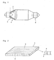
- FIG. 2 is a perspective view of a matte schematically showing a detailed structure of the matte.
- The invention is a heat insulating member for an end cone portion obtained by blowing alumina-silica based ceramic fibers through a sol-gel process to obtain a continuous sheet and folding and laminating it every a given length or piling plural cut sheets one upon the other to form a matte and then subjecting the matte to needling in a sheet lamination direction perpendicular to a surface of the matte. The feature thereof lies in that the composition of the matte inclusive of the needle is alumina:silica = 60-80:40-20.
- In the invention, the alumina-silica based ceramic fibers are desirable to utilize a precursor for alumina-silica based ceramic fiber (hereinafter referred to "aluminous fiber" simply) obtained by adding silica sol to an aqueous solution of a basic aluminum chloride having Al/Cl = 1.8 (atomic ratio) (aluminum content = 70 g/l) so as to render a composition ratio of alumina to silica into 60-80:40-20. The reason why the composition of the precursor for the aluminous fiber is limited to the above is due to the fact that when the alumina content is less than 60 mass% or the silica content is less than 20 mass%, silica becomes rich and the heat resistance is lacking and the hot reaction force lowers, while when the alumina content exceeds 80 mass% or the silica content exceeds 40 mass%, alumina becomes rich and the brittleness becomes high to lower the toughness and the fiber strength against vibration of the vehicle or shock of the exhaust gas is not obtained. Moreover, the composition is preferable to be 70-74:30-26.
- The aluminous fiber is obtained by adding an organic polymer such as polyvinyl alcohol or the like to the precursor for the aluminous fiber and concentrating them to form a spinning solution and then spinning this spinning solution through a blowing process. That is, the aluminous fibers are produced by adjusting an aperture size in the blowing to provide an average fiber length of not less than 50 µm but not more than 100 mm. When the length of the aluminous fiber is less than 50 µm, the fibers do not entangle with each other in the needling and the strength is lacking but also the wind erosion is easily caused in the contacting with the exhaust gas, while when it exceeds 100 mm, the fiber length is too long and the restraining force through the matte thickness lowers in the needling and the matte becomes too bulk and the assembling is difficult. Moreover, the average fiber length is preferable to be not less than 10 mm but not more than 70 mm.
- Then, the aforementioned aluminous fibers are fibrillated by blowing through a sol-gel process and laminated to produce laminate sheets of the aluminous fibers or a matte. The thus produced matte of the aluminous fibers is subjected to a needling treatment.
- Moreover, the needling treatment means a treatment for folding or laminating the sheets of the aluminous fibers to suppress the bulk height and make thin and hard to thereby facilitate the handling but also enhancing the strengthening between the laminated sheets. According to this treatment, the aluminous fibers are introduced in a direction perpendicular to the matte surface of the aluminous fiber sheets (thickness direction of the sheet laminate) or a direction directing to the longitudinal direction, which results in the complexedly entangled orientation into three-dimensional direction and hence brings about the strengthening between the laminated sheets forming the matte of the aluminous fibers.
- In such a needling treatment, the distance between the adjoining needles in a horizontal direction (XY direction) introduced in the thickness direction of the laminated sheets is 1-100 mm, preferably 2-10 man. When the distance is less than 1 mm, the sufficient strengthening between the laminated sheets is not obtained and there is a fear of causing the peeling between the laminated sheets in the assembling onto the end cone portion of the exhaust pipe, while when it exceeds 100 mm, the sufficient elastic force is not yet obtained even by the orientation of the fibers introduced in the thickness direction through the needling and there is a fear of detaching from the end cone portion of the exhaust pipe. As shown in FIG. 2, when the needling orientation length is s and the thickness of the matte is h and an angle defined by s and h is a needling orientation angle A, the needling is carried at an angle of A (h/s) = 0.5-0.87.
- Then, the matte (laminated sheets) of the aluminous fibers subjected to the needling treatment is raised from room temperature and continuously fired at a highest temperature of 1250 ± 50°C to obtain a matter made of aluminous fiber laminated sheets having given thickness and composition.
- The thus obtained aluminous fiber matte (continuous laminated sheets) is cut for facilitating the handling operation at subsequent step. In this case, it may be effective to control alumina spherical solid matter called as shots included in the aluminous fiber matte. The shots are produced in the course of blowing the spinning solution. When the amount of the shots is not less than 7 mass%, the damage of the aluminous fibers may be caused in the mounting of the matte onto the end cone portion. Particularly, this phenomenon is conspicuous when the bulk density of the matte after the needling treatment (GBD) is 0.2-0.55 g/cm3. If the above damage is caused, the wind erosion is easily caused in case of contacting with the high temperature exhaust gas, and the clogging in the catalyst is caused by fiber dust generated.
- Then, the cut matte (continuous laminated sheets) is subjected to an impregnation treatment with an organic binder. This treatment is carried out for assisting the easy operation in the assembling of the heat insulating member onto the end cone portion. As the organic binder can be used various rubbers, thermoplastic resins, thermosetting resins and the like. As the rubber may be used natural rubber; acrylic rubbers such as ethylacrylate-chloroethyl vinyl ether copolymer, n-butylacrylate-acrylonitrile copolymer, ethylacrylate-acrylonitrile copolymer and the like; nitrile rubber such as butadiene-acrylonitrile copolymer and the like; butadiene rubber and so on. As the thermoplastic resin may be used acrylic resins such as homopolymers or copolymers of acrylic acid, acrylic ester, acrylamide, acrylonitrile, methacrylic acid, methacrylic ester and the like; acrylonitrile-styrene copolymer; acrylonitrile-butadiene-styrene copolymer and so on. As the thermosetting resin may be used bisphenol type epoxy resin, novolac type epoxy resin and the like. Among the above organic binders, the acrylic resin such as acrylic or methacrylic polymer and the like are effective.
- Concretely, the impregnation treatment is carried out by preparing an aqueous dispersion from the above acrylic resin and water and then impregnating the surface of the matte with the dispersion. In general, the matte of the aluminous fibers contains the resin (solid content) in an amount larger than the required amount together with water through the impregnation treatment, so that the excess solid content should be removed. The removal of the solid content can be carried out by suction at a suction force of about 1-50 kPa for 1 second or more.
- In the laminated sheets of the aluminous fibers at this stage is still contained water in addition to the solid content, so that it is required to remove water. The removal of water can be carried out by heating,
pressurizing and drying. In this step, if the matte of the aluminous fibers including the organic binder itself is compressed together with the removal of water, the assembling operation onto the end cone portion of the exhaust pipe is facilitated but also the organic binder is burnt out during the supply of the high temperature exhaust gas to expendably restore the compressed matte of the aluminous fibers, which is strongly kept between the outer cone and the inner cone. - The temperature of the compression drying is preferable to be about 95-155°C. When the drying temperature is lower than 95°C, the drying time becomes long and the production efficiency is poor, while when it exceeds 155°C, the decomposition of the organic binder starts to damage the adhesion ability of the organic binder. The drying time is preferable to be not less than 100 seconds. When the time is shorter than the above value, the drying is not sufficiently attained. Further, the pressurization in the drying is carried out by heating under a condition of 5-30 MPa so as to render a thickness after the compression into 4-15 mm. For example, when the compression thickness is less than 4 mm and the pressure is higher than 30 MPa, the damage of the ceramic fibers such as aluminous fibers and the like is caused, while when the compression thickness is more than 15 mm and the pressure is lower than 5 MPa, the necessary compression effect is not obtained.
- Thereafter, the heated, pressurized and dried matte of the ceramic fibers such as aluminous fibers and the like (laminated sheets) is cut into a heat insulating member for the end cone portion.
- Example 1
(Production of matte: laminated sheets)
To an aqueous solution of basic aluminum chloride having an aluminum content of 70 g/l and Al/Cl = 1.8 (atomic ratio) is added silica sol so that a composition of aluminous fibers is Al2O3:SiO2 = 72±2:28±2 to obtain a precursor of aluminous fibers as a ceramic fiber. Then, an organic polymer such as polyvinyl alcohol or the like is added to the precursor of aluminous fibers to prepare a concentrated spinning solution. A continuous sheet is prepared by adjusting a size of a blowing orifice so as to provide an average fiber length of 60 mm when this spinning solution is spun through a blowing process, and laminated one upon the other to produce continuous laminated sheets of aluminous fibers. - The thus produced continuous laminated sheets of aluminous fibers are subjected to a needling treatment at a distance between mutual needles of 2 mm and a needling orientation angle of A = 0.7. Then, the continuous laminated sheets are heated from room temperature and continuously fired at a maximum temperature of 1250±50°C to obtain an aluminous fiber lamination sheet of 1050 g/cm2.
- (Cutting of lamination sheet)
The continuous lamination sheet of aluminous fibers is cut into a matte having a width of 500-1400 mm, a length of 50000-55000 mm and a thickness of 10 mm. As to shots included in the matte, it is confirmed that not more than 7 mass% of the shots of not less than 45 µm is included in the matte as measured by a sieve and a weighing meter. - (Resin impregnation)
The matte of the aluminous fiber continuous laminated sheets obtained in the above step is subjected to an impregnation with an organic resin by providing an aqueous dispersion of an acrylic resin (solid content: 50±10 mass%, pH: 5.5-7.0) so as to adjust a resin concentration to 0.5-30 mass% and impregnating the aqueous dispersion of the acrylic resin into the surface of the matte cut at 1280 mm on a conveyor. At this stage, a greater amount of the solid content is adhered to the matte of the aluminous fiber laminated sheets. - (Suction of solid content)
After the impregnation treatment with the resin, the excess solid content adhered to the matte is removed by suction. In this case, the solid content is removed by suctioning the matte at a suction force of 5-50 kPa for not less than 1 second. After this treatment, the impregnation ratio of the resin is 55 mass% per the weight of the matte as measured by a weighing meter. - (Drying)
The matte of the aluminous fibers after the suction is dried by heating under pressure at a drying temperature of 95-155°C and a compression width in the drying of 4-15 mm for a drying time of not less than 100 seconds. The thus obtained matte of the aluminous fibers have a resin adhesion ratio of 10 mass% per the weight of the matte as measured by the weighing meter and a thickness of 3-15 mm. Moreover, the matte is punched, if necessary. - Example 2
(Production of matte: lamination sheet)
To an aqueous solution of basic aluminum chloride having an aluminum content of 70 g/l and Al/Cl = 1.8 (atomic ratio) is added silica sol so that a composition of aluminous fibers is Al2O3:SiO2 = 72±2:28±2 to obtain a precursor of aluminous fibers as a ceramic fiber. Then, an organic polymer such as polyvinyl alcohol or the like is added to the precursor of aluminous fibers to prepare a concentrated spinning solution. A continuous sheet is prepared by adjusting a size of a blowing orifice so as to provide an average fiber length of 12 mm when this spinning solution is spun through a blowing process, and laminated one upon the other to produce continuous laminated sheets of aluminous fibers. - The thus produced continuous laminated sheets of aluminous fibers are subjected to a needling treatment at a distance between mutual needles of 2 mm and a needling orientation angle of A = 0.7. Then, the continuous laminated sheets are heated from room temperature and continuously fired at a maximum temperature of 1250±50°C to obtain an aluminous fiber lamination sheet of 1050 g/cm2.
- (Cutting of lamination sheet)
The continuous lamination sheet of aluminous fibers is cut into a matte having a width of 500-1400 mm, a length of 51000-52500 mm and a thickness of 10 mm. As to shots included in the matte, it is confirmed that not more than 7 mass% of the shots of not less than 45 µm is included in the matte as measured by a sieve and a weighing meter. - (Resin impregnation)
The matte of the aluminous fiber continuous laminated sheets obtained in the above step is subjected to an impregnation with an organic resin by providing an aqueous dispersion of an acrylic resin (solid content: 50±10 mass%, pH: 5.5-7.0) so as to adjust a resin concentration to 0.5-30 mass% and impregnating the aqueous dispersion of the acrylic resin into the surface of the matte cut at 500-1400 mm on a conveyor. At this stage, a greater amount of the solid content is adhered to the matte of the aluminous fiber laminated sheets. - (Suction of solid content)
After the impregnation treatment with the resin, the excess solid content adhered to the matte is removed by suction. In this case, the solid content is removed by suctioning the matte at a suction force of 5-50 kPa for not less than 1 second. After this treatment, the impregnation ratio of the resin is 55 mass% per the weight of the matte as measured by a weighing meter. - (Drying)
The matte of the aluminous fibers after the suction is dried by heating under pressure at a drying temperature of 95-155°C and a compression width in the drying of 4-15 mm for a drying time of not less than 100 seconds. The thus obtained matte of the aluminous fibers have a resin adhesion ratio of 10 mass% per the weight of the matte as measured by the weighing meter and a thickness of 3-15 mm. Moreover, the matte is punched, if necessary. - Reference Example 1
A matte of aluminous fibers is prepared in the same manner as in Example 1 except that silica sol is added to the aqueous solution of the basic aluminum chloride having an aluminum content of 70 g/l and Al/Cl = 1.8 (atomic ratio) so as to render a composition of aluminous fibers into Al2O3:SiO2 = 80±2:20±2. - Reference Example 2
A matte of aluminous fibers is prepared in the same manner as in Example 1 except that silica sol is added to the aqueous solution of the basic aluminum chloride having an aluminum content of 70 g/l and Al/Cl = 1.8 (atomic ratio) so as to render a composition of aluminous fibers into Al2O3:SiO2 = 60±2:40±2. - Reference Example 3
A matte of aluminous fibers is prepared in the same manner as in Example 1 except that the aluminous fibers are cut into an average fiber length of 0.25 mm after the completion of the spinning through a blowing process. - Reference Example 4
A matte of aluminous fibers is prepared in the same manner as in Example 1 except that the needling is carried out at an angle corresponding to a needling orientation angle of A = 0.42. - Reference Example 5
A matte of aluminous fibers is prepared in the same manner as in Example 1 except that the distance between needles is 10 mm. - Comparative Example 1
A starting material having a composition of Al2O3:SiO2 = 50±2:50±2 is electrically melted, which is blown through a high pressure air stream to form fibers, which is mixed with 8 parts by mass of an organic binder (acryl emulsion) based on 100 parts by mass of the resulting aluminous fibers having an average fiber length of 2 mm to prepare an aqueous slurry for a matte layer. Then, the aqueous slurry for the matte layer is adhered to a surface of a flat stainless net of 200 mesh and dehydrated by suction to obtain a wet shaped body having a thickness of 8 mm. The wet shaped body is pressed to obtain a wet shaped body having a thickness of 5 mm. Thereafter, the wet shaped body is dried at 100-140°C for 1 hour to obtain a ceramic fiber heat insulating member having a composition of Al2O3:SiO2 = 50±2:50±2. - Comparative Example 2
A matte of aluminous fibers is prepared in the same manner as in Example 1 except that silica sol is added to the aqueous solution of the basic aluminum chloride having an aluminum content of 70 g/l and Al/Cl = 1.8 (atomic ratio) so as to render a composition of aluminous fibers into Al2O3:SiO2 = 85±2:15±2. - Comparative Example 3
A matte of aluminous fibers is prepared in the same manner as in Example 1 except that silica sol is added to the aqueous solution of the basic aluminum chloride having an aluminum content of 70 g/l and Al/Cl = 1.8 (atomic ratio) so as to render a composition of aluminous fibers into Al2O3:SiO2 = 55±2:45±2. - Comparative Example 4
A matte of aluminous fibers is prepared in the same manner as in Example 1 except that the aluminous fibers are cut into an average fiber length of 0.2 mm after the completion of the spinning through a blowing process. - Comparative Example 5
A matte of aluminous fibers is prepared in the same manner as in Example 1 except that the needling is carried out at an angle corresponding to a needling orientation angle of A = 65°. - Comparative Example 6
A matte of aluminous fibers is prepared in the same manner as in Example 1 except that the distance between needles is 12 mm.
- Moreover, the tests for the properties of the mattes in the above examples, reference examples and comparative examples are carried out under the following conditions.
- (Measurement of average fiber length)
Fibers are taken out from a sample through pincette and placed on a slide glass and observed by means of a polarizing microscope having objective lens of 40x10 to measure optional 100 fiber lengths with a scale. - As seen from the test results, the average fiber length of the aluminous fibers is important to be not less than 50 µm. Also, it is seen that the upper limit of the average fiber length is 100 mm.
- (Thermal conductivity)
Cut samples of 100 x 100 mm are piled one upon the other so as to have a constant bulk density of 0.3 g/cm3 and compressed to adjust the weight. Then, a heating wire and thermocouple are interposed in the vicinity of the center of the sample and sandwiched between compression plates so as to adjust a thickness to 100 mm. Thereafter, they are placed in an electric furnace to conduct the measurement after the temperature (600-1000°C) becomes stable. The measurement is repeated at thesame temperature 3 times or more at an interval of not less than 10 minutes and an average value thereof is calculated as a thermal conductivity to form a graph between temperature and thermal conductivity. - As seen from the test results, the thermal conductivity is required to be not more than 0.2 W/m*K at a bulk density (GBD) of 0.2-0.4 g/cm3. Also, it is required that the thermal conductivity at a temperature of 600-800°C is not more than 0.15 W/m*K and the thermal conductivity at a temperature of 800-1000°C is 0.18 W/m*K.
- (Wind erosion property)
Cut samples of 40x25 mm are laminated so as to provide a constant bulk density of 0.3 g/cm3 and compressed using SUS jig with a spacer and set in a furnace for wind erosion test heated to 800°C and then left to stand for 1 hour. Then, air is exposed through an air nozzle at a pressure of 1.5 kg/cm2 for 3 hours and a wind eroded distance after the test is measured. The wind eroded distance per 3 hours is calculated to forma graph between GBD and wind eroded distance. In case of passing through the sample within 3 hours, the rapid temperature changing point is a through point, from which is calculated the test time. - As seen from the test results, the wind eroded distance is required to be not more than 8 mm at the bulk density (GBD) of 0.3 g/cm3. Also, the wind eroded distance is desirable to be not more than 4 mm at the bulk density (GB) of 0.3 g/cm3.
- (Tensile strength)
A cut sample of 200 x 50 mm is fixed at upper and lower margins of 50 x 30 mm and tensioned at a rate of 10 mm/min upward to measure a maximum value of a load at tension. Then, a tensile strength per unit area is calculated by the following equation using a sectional area calculated from the sample thickness x sample width of 50 mm:

- The invention is a heat insulating member used in an end cone portion of an exhaust gas conversion apparatus for an internal engine such as diesel engine or the like, or an apparatus connected to an exhaust pipe for a turbine engine or the like. Further, the invention can be used as a heat insulating member for the exhaust pipe other than the end cone portion or as a sound absorption or sound proof member for the exhaust pipe.
Claims (5)
- A heat insulating member for an end cone portion of an exhaust gas conversion apparatus, formed by laminating sheets each made of alumina-silica based ceramic fibers to form a matte and subjecting the matte to needling in a lamination direction of the sheets, in which a composition of the ceramic fiber used in the matte is alumina:silica = 60-80:40-20.
- A heat insulating member according to claim 1, wherein the composition of alumina to silica is 70-74:30-26.
- A heat insulating member according to claim 1 or 2, wherein the ceramic fiber has an average fiber length of not less than 50 µm but not more than 100 mm.
- A heat insulating member according to anyone of claims 1 to 3, wherein the needling is carried out at a distance between mutual needles of 1-100 mm.
- A heat insulating member according to anyone of claims 1 to 4, wherein the needling is carried out at an orientation angle of not more than 60° with respect to a direction perpendicular to the surface of the matte.
Applications Claiming Priority (1)
| Application Number | Priority Date | Filing Date | Title |
|---|---|---|---|
| JP2005016907A JP4663341B2 (en) | 2005-01-25 | 2005-01-25 | Heat insulation material for end cone part of exhaust gas purifier |
Publications (2)
| Publication Number | Publication Date |
|---|---|
| EP1696110A1 true EP1696110A1 (en) | 2006-08-30 |
| EP1696110B1 EP1696110B1 (en) | 2008-01-16 |
Family
ID=36123927
Family Applications (1)
| Application Number | Title | Priority Date | Filing Date |
|---|---|---|---|
| EP20060290138 Active EP1696110B1 (en) | 2005-01-25 | 2006-01-20 | Heat insulating member for end cone portion of exhaust gas conversion apparatus |
Country Status (7)
| Country | Link |
|---|---|
| US (1) | US7442347B2 (en) |
| EP (1) | EP1696110B1 (en) |
| JP (1) | JP4663341B2 (en) |
| KR (1) | KR100786048B1 (en) |
| CN (1) | CN100410506C (en) |
| DE (1) | DE602006000431T2 (en) |
| TW (1) | TWI290189B (en) |
Cited By (28)
| Publication number | Priority date | Publication date | Assignee | Title |
|---|---|---|---|---|
| EP1908934A1 (en) * | 2006-09-29 | 2008-04-09 | Ibiden Co., Ltd. | Laminated sheet, method of producing the sheet, exhaust gas processing device, and method of producing the device |
| EP2058425A1 (en) * | 2007-11-06 | 2009-05-13 | Ibiden Co., Ltd. | Mat material and exhaust gas treatment device |
| WO2010062591A1 (en) * | 2008-11-03 | 2010-06-03 | 3M Innovative Properties Company | Mounting mat and pollution control device with the same |
| WO2011084487A1 (en) * | 2009-12-17 | 2011-07-14 | Unifrax I Llc | Mounting mat for exhaust gas treatment device |
| US8071040B2 (en) | 2009-09-23 | 2011-12-06 | Unifax I LLC | Low shear mounting mat for pollution control devices |
| US8075843B2 (en) | 2009-04-17 | 2011-12-13 | Unifrax I Llc | Exhaust gas treatment device |
| EP2436890A1 (en) * | 2010-09-30 | 2012-04-04 | Ibiden Co., Ltd. | Mat, holding sealing material, method for producing mat, and exhaust gas purifying apparatus |
| US8211373B2 (en) | 2008-08-29 | 2012-07-03 | Unifrax I Llc | Mounting mat with flexible edge protection and exhaust gas treatment device incorporating the mounting mat |
| US8263512B2 (en) | 2008-12-15 | 2012-09-11 | Unifrax I Llc | Ceramic honeycomb structure skin coating |
| US8343400B2 (en) | 2010-04-13 | 2013-01-01 | 3M Innovative Properties Company | Methods of making inorganic fiber webs |
| US8349265B2 (en) | 2010-08-13 | 2013-01-08 | Unifrax I Llc | Mounting mat with flexible edge protection and exhaust gas treatment device incorporating the mounting mat |
| US8524161B2 (en) | 2007-08-31 | 2013-09-03 | Unifrax I Llc | Multiple layer substrate support and exhaust gas treatment device |
| US8562879B2 (en) | 2010-04-13 | 2013-10-22 | 3M Innovative Properties Company | Inorganic fiber webs and methods of making and using |
| US8679415B2 (en) | 2009-08-10 | 2014-03-25 | Unifrax I Llc | Variable basis weight mounting mat or pre-form and exhaust gas treatment device |
| US8734726B2 (en) | 2009-12-17 | 2014-05-27 | Unifrax I Llc | Multilayer mounting mat for pollution control devices |
| US8765069B2 (en) | 2010-08-12 | 2014-07-01 | Unifrax I Llc | Exhaust gas treatment device |
| US8834758B2 (en) | 2010-04-13 | 2014-09-16 | 3M Innovative Properties Company | Thick inorganic fiber webs and methods of making and using |
| US8834759B2 (en) | 2010-04-13 | 2014-09-16 | 3M Innovative Properties Company | Inorganic fiber webs and methods of making and using |
| US8887863B2 (en) | 2008-04-30 | 2014-11-18 | Ibiden Co., Ltd. | Mat member, method for manufacturing the mat member, muffler and method for manufacturing the muffler |
| US8916102B2 (en) | 2008-11-03 | 2014-12-23 | 3M Innovative Properties Company | Mounting mat and pollution control device with the same |
| US8926911B2 (en) | 2009-12-17 | 2015-01-06 | Unifax I LLC | Use of microspheres in an exhaust gas treatment device mounting mat |
| US8951323B2 (en) | 2009-09-24 | 2015-02-10 | Unifrax I Llc | Multiple layer mat and exhaust gas treatment device |
| US9120703B2 (en) | 2010-11-11 | 2015-09-01 | Unifrax I Llc | Mounting mat and exhaust gas treatment device |
| US9174169B2 (en) | 2009-08-14 | 2015-11-03 | Unifrax I Llc | Mounting mat for exhaust gas treatment device |
| US9452719B2 (en) | 2015-02-24 | 2016-09-27 | Unifrax I Llc | High temperature resistant insulation mat |
| US9631529B2 (en) | 2009-04-21 | 2017-04-25 | Saffil Automotive Limited | Erosion resistant mounting mats |
| US9650935B2 (en) | 2009-12-01 | 2017-05-16 | Saffil Automotive Limited | Mounting mat |
| US9924564B2 (en) | 2010-11-11 | 2018-03-20 | Unifrax I Llc | Heated mat and exhaust gas treatment device |
Families Citing this family (17)
| Publication number | Priority date | Publication date | Assignee | Title |
|---|---|---|---|---|
| JP5014113B2 (en) * | 2007-01-26 | 2012-08-29 | イビデン株式会社 | Sheet material, method for manufacturing the same, exhaust gas treatment device, and silencer |
| WO2009032191A1 (en) * | 2007-08-31 | 2009-03-12 | Unifrax I Llc | Exhaust gas treatment device |
| JP2009085091A (en) | 2007-09-28 | 2009-04-23 | Ibiden Co Ltd | Mat material, exhaust gas treating device, and muffler |
| JP2009085093A (en) * | 2007-09-28 | 2009-04-23 | Ibiden Co Ltd | Mat member, method for manufacturing mat member, exhaust gas treatment apparatus and muffler |
| JP4959499B2 (en) * | 2007-09-28 | 2012-06-20 | イビデン株式会社 | Mat material, exhaust gas treatment device and silencer |
| JP2010096171A (en) * | 2008-04-30 | 2010-04-30 | Ibiden Co Ltd | Mat material, method for manufacturing mat material, muffler, and method for manufacturing muffler |
| JP4931856B2 (en) * | 2008-05-07 | 2012-05-16 | 株式会社三五 | Dust absorption method and dust absorption apparatus for exhaust gas treatment device |
| JP5079630B2 (en) * | 2008-08-08 | 2012-11-21 | 株式会社小松製作所 | Exhaust gas purification device |
| JP5499644B2 (en) | 2009-11-06 | 2014-05-21 | 三菱樹脂株式会社 | Inorganic fiber molded body and method for producing the same |
| US8424636B2 (en) * | 2011-04-29 | 2013-04-23 | E.I. Du Pont De Nemours And Company | Muffler assembly and process of manufacture |
| JP2012189081A (en) * | 2012-04-26 | 2012-10-04 | Ibiden Co Ltd | Mat material, method for manufacturing the same, exhaust gas treatment apparatus and muffler |
| JP2017525125A (en) * | 2014-07-21 | 2017-08-31 | 宋正▲賢▼ | About one electric heating device and its manufacturing method |
| JP6386342B2 (en) * | 2014-10-29 | 2018-09-05 | イビデン株式会社 | Method for manufacturing exhaust gas purification device |
| CN105370367A (en) * | 2015-11-30 | 2016-03-02 | 重庆祥吉机械制造有限公司 | Heat-insulating cover for engine |
| JP2021185310A (en) * | 2019-08-06 | 2021-12-09 | 三菱ケミカル株式会社 | Mat for exhaust emission control system and exhaust emission control system |
| JP7088892B2 (en) * | 2019-10-11 | 2022-06-21 | イビデン株式会社 | Insulation sheet for assembled battery and assembled battery |
| CN113173772B (en) * | 2021-05-10 | 2023-03-17 | 河南省西峡开元冶金材料有限公司 | Method for manufacturing polycrystalline alumina fiber gasket |
Citations (6)
| Publication number | Priority date | Publication date | Assignee | Title |
|---|---|---|---|---|
| EP0450348A1 (en) * | 1990-03-28 | 1991-10-09 | HEINRICH GILLET GmbH & CO. KG | Catalytic converter for internal combustion engines |
| US5250269A (en) | 1992-05-21 | 1993-10-05 | Minnesota Mining And Manufacturing Company | Catalytic converter having a metallic monolith mounted by a heat-insulating mat of refractory ceramic fibers |
| US5580532A (en) * | 1993-04-22 | 1996-12-03 | Unifrax Corporation | Mounting mat for fragile structures such as catalytic converters |
| JPH11117731A (en) | 1997-10-20 | 1999-04-27 | Ibiden Co Ltd | Catalytic coverter for exhaust emission control |
| EP1267048A1 (en) * | 2000-03-22 | 2002-12-18 | Ibiden Co., Ltd. | Catalyst converter and diesel particulate filter system |
| WO2003000414A1 (en) * | 2001-06-22 | 2003-01-03 | 3M Innovative Properties Company | Catalyst carrier holding material and catalytic converter |
Family Cites Families (15)
| Publication number | Priority date | Publication date | Assignee | Title |
|---|---|---|---|---|
| US2161676A (en) * | 1935-11-08 | 1939-06-06 | Houdry Process Corp | Catalytic operation |
| JPS5130555B2 (en) * | 1971-09-03 | 1976-09-01 | ||
| US4144195A (en) * | 1974-09-24 | 1979-03-13 | Volkswagenwerk Aktiengesellschaft | High temperature resistant, heat insulating ceramic material |
| JPS604151B2 (en) * | 1975-09-29 | 1985-02-01 | トヨタ自動車株式会社 | Ceramic fiber moldings for manifolds and reactors |
| US4847140A (en) * | 1985-04-08 | 1989-07-11 | Helmic, Inc. | Nonwoven fibrous insulation material |
| JPS61172193U (en) * | 1985-04-15 | 1986-10-25 | ||
| US4863700A (en) * | 1985-04-16 | 1989-09-05 | Stemcor | Monolithic catalytic converter mounting arrangement |
| WO1994016134A1 (en) * | 1993-01-07 | 1994-07-21 | Minnesota Mining And Manufacturing Company | Flexible nonwoven mat |
| JP3282362B2 (en) | 1994-04-15 | 2002-05-13 | 三菱化学株式会社 | Grasping material for exhaust gas purification equipment |
| US5996228A (en) * | 1995-04-13 | 1999-12-07 | Mitsubishi Chemical Corporation | Monolith-holding element, process for producing the same, catalytic converter using a monolith member and process for producing the same |
| EP1336678B1 (en) | 1998-07-07 | 2004-10-20 | Mitsubishi Chemical Corporation | Continuous alumina fiber sheet |
| US6613296B1 (en) * | 2000-01-31 | 2003-09-02 | Delphi Technologies, Inc. | Relieved support material for catalytic converter and the process of making the same |
| JP2002129455A (en) * | 2000-10-17 | 2002-05-09 | Ibiden Co Ltd | Sealing material for supporting catalyst converter, method of producing the same and catalyst converter |
| US7261864B2 (en) * | 2001-06-22 | 2007-08-28 | 3M Innovative Properties Company | Catalyst carrier holding material and catalytic converter |
| CN100359071C (en) * | 2002-06-28 | 2008-01-02 | 电气化学工业株式会社 | Inorganic staple fiber accumulation for holding material, process for producing the same and holding material |
-
2005
- 2005-01-25 JP JP2005016907A patent/JP4663341B2/en active Active
- 2005-12-30 TW TW94147611A patent/TWI290189B/en active
-
2006
- 2006-01-18 US US11/333,513 patent/US7442347B2/en active Active
- 2006-01-20 DE DE200660000431 patent/DE602006000431T2/en active Active
- 2006-01-20 KR KR1020060006228A patent/KR100786048B1/en active IP Right Grant
- 2006-01-20 EP EP20060290138 patent/EP1696110B1/en active Active
- 2006-01-25 CN CNB2006100029306A patent/CN100410506C/en active Active
Patent Citations (6)
| Publication number | Priority date | Publication date | Assignee | Title |
|---|---|---|---|---|
| EP0450348A1 (en) * | 1990-03-28 | 1991-10-09 | HEINRICH GILLET GmbH & CO. KG | Catalytic converter for internal combustion engines |
| US5250269A (en) | 1992-05-21 | 1993-10-05 | Minnesota Mining And Manufacturing Company | Catalytic converter having a metallic monolith mounted by a heat-insulating mat of refractory ceramic fibers |
| US5580532A (en) * | 1993-04-22 | 1996-12-03 | Unifrax Corporation | Mounting mat for fragile structures such as catalytic converters |
| JPH11117731A (en) | 1997-10-20 | 1999-04-27 | Ibiden Co Ltd | Catalytic coverter for exhaust emission control |
| EP1267048A1 (en) * | 2000-03-22 | 2002-12-18 | Ibiden Co., Ltd. | Catalyst converter and diesel particulate filter system |
| WO2003000414A1 (en) * | 2001-06-22 | 2003-01-03 | 3M Innovative Properties Company | Catalyst carrier holding material and catalytic converter |
Cited By (44)
| Publication number | Priority date | Publication date | Assignee | Title |
|---|---|---|---|---|
| US8328986B2 (en) | 2006-09-29 | 2012-12-11 | Ibiden Co., Ltd. | Laminated sheet, method of producing the sheet, exhaust gas processing device, and method of producing the device |
| EP1908934A1 (en) * | 2006-09-29 | 2008-04-09 | Ibiden Co., Ltd. | Laminated sheet, method of producing the sheet, exhaust gas processing device, and method of producing the device |
| US8524161B2 (en) | 2007-08-31 | 2013-09-03 | Unifrax I Llc | Multiple layer substrate support and exhaust gas treatment device |
| EP2058425A1 (en) * | 2007-11-06 | 2009-05-13 | Ibiden Co., Ltd. | Mat material and exhaust gas treatment device |
| US8038758B2 (en) | 2007-11-06 | 2011-10-18 | Ibiden Co., Ltd. | Mat material and exhaust gas treatment device |
| CN101429886B (en) * | 2007-11-06 | 2011-11-09 | 揖斐电株式会社 | Mat material and exhaust gas treatment device |
| US8887863B2 (en) | 2008-04-30 | 2014-11-18 | Ibiden Co., Ltd. | Mat member, method for manufacturing the mat member, muffler and method for manufacturing the muffler |
| US8211373B2 (en) | 2008-08-29 | 2012-07-03 | Unifrax I Llc | Mounting mat with flexible edge protection and exhaust gas treatment device incorporating the mounting mat |
| WO2010062591A1 (en) * | 2008-11-03 | 2010-06-03 | 3M Innovative Properties Company | Mounting mat and pollution control device with the same |
| US9290866B2 (en) | 2008-11-03 | 2016-03-22 | 3M Innovative Properties Company | Mounting mat and pollution control device with the same |
| US8916102B2 (en) | 2008-11-03 | 2014-12-23 | 3M Innovative Properties Company | Mounting mat and pollution control device with the same |
| US9163148B2 (en) | 2008-12-15 | 2015-10-20 | Unifrax I Llc | Ceramic honeycomb structure skin coating |
| US8679615B2 (en) | 2008-12-15 | 2014-03-25 | Unifrax I Llc | Ceramic honeycomb structure skin coating |
| US8263512B2 (en) | 2008-12-15 | 2012-09-11 | Unifrax I Llc | Ceramic honeycomb structure skin coating |
| US8696807B2 (en) | 2008-12-15 | 2014-04-15 | Unifrax I Llc | Ceramic honeycomb structure skin coating |
| US8075843B2 (en) | 2009-04-17 | 2011-12-13 | Unifrax I Llc | Exhaust gas treatment device |
| US9631529B2 (en) | 2009-04-21 | 2017-04-25 | Saffil Automotive Limited | Erosion resistant mounting mats |
| US8679415B2 (en) | 2009-08-10 | 2014-03-25 | Unifrax I Llc | Variable basis weight mounting mat or pre-form and exhaust gas treatment device |
| US9174169B2 (en) | 2009-08-14 | 2015-11-03 | Unifrax I Llc | Mounting mat for exhaust gas treatment device |
| US8071040B2 (en) | 2009-09-23 | 2011-12-06 | Unifax I LLC | Low shear mounting mat for pollution control devices |
| US8951323B2 (en) | 2009-09-24 | 2015-02-10 | Unifrax I Llc | Multiple layer mat and exhaust gas treatment device |
| US9650935B2 (en) | 2009-12-01 | 2017-05-16 | Saffil Automotive Limited | Mounting mat |
| US9816420B2 (en) | 2009-12-17 | 2017-11-14 | Unifrax I Llc | Mounting mat for exhaust gas treatment device |
| US8734726B2 (en) | 2009-12-17 | 2014-05-27 | Unifrax I Llc | Multilayer mounting mat for pollution control devices |
| CN102844536B (en) * | 2009-12-17 | 2017-03-22 | 尤尼弗瑞克斯 I 有限责任公司 | Mounting mat for exhaust gas treatment device |
| CN102844536A (en) * | 2009-12-17 | 2012-12-26 | 尤尼弗瑞克斯I有限责任公司 | Mounting mat for exhaust gas treatment device |
| WO2011084487A1 (en) * | 2009-12-17 | 2011-07-14 | Unifrax I Llc | Mounting mat for exhaust gas treatment device |
| US8926911B2 (en) | 2009-12-17 | 2015-01-06 | Unifax I LLC | Use of microspheres in an exhaust gas treatment device mounting mat |
| US8343400B2 (en) | 2010-04-13 | 2013-01-01 | 3M Innovative Properties Company | Methods of making inorganic fiber webs |
| US8834758B2 (en) | 2010-04-13 | 2014-09-16 | 3M Innovative Properties Company | Thick inorganic fiber webs and methods of making and using |
| US9393449B2 (en) | 2010-04-13 | 2016-07-19 | 3M Innovative Properties Company | Thick inorganic fiber webs and methods of making and using |
| US8562879B2 (en) | 2010-04-13 | 2013-10-22 | 3M Innovative Properties Company | Inorganic fiber webs and methods of making and using |
| US9956441B2 (en) | 2010-04-13 | 2018-05-01 | 3M Innovative Properties Company | Inorganic fiber webs and methods of making and using |
| US8834759B2 (en) | 2010-04-13 | 2014-09-16 | 3M Innovative Properties Company | Inorganic fiber webs and methods of making and using |
| US8765069B2 (en) | 2010-08-12 | 2014-07-01 | Unifrax I Llc | Exhaust gas treatment device |
| US8992846B2 (en) | 2010-08-12 | 2015-03-31 | Unifrax I Llc | Exhaust gas treatment device |
| US8349265B2 (en) | 2010-08-13 | 2013-01-08 | Unifrax I Llc | Mounting mat with flexible edge protection and exhaust gas treatment device incorporating the mounting mat |
| EP2436890A1 (en) * | 2010-09-30 | 2012-04-04 | Ibiden Co., Ltd. | Mat, holding sealing material, method for producing mat, and exhaust gas purifying apparatus |
| CN102444452B (en) * | 2010-09-30 | 2014-08-13 | 揖斐电株式会社 | Mat, holding sealing material, method for producing mat, and exhaust gas purifying apparatus |
| CN102444452A (en) * | 2010-09-30 | 2012-05-09 | 揖斐电株式会社 | Mat, holding sealing material, method for producing mat, and exhaust gas purifying apparatus |
| US8574334B2 (en) | 2010-09-30 | 2013-11-05 | Ibiden Co., Ltd. | Mat, holding sealing material, method for producing mat, and exhaust gas purifying apparatus |
| US9120703B2 (en) | 2010-11-11 | 2015-09-01 | Unifrax I Llc | Mounting mat and exhaust gas treatment device |
| US9924564B2 (en) | 2010-11-11 | 2018-03-20 | Unifrax I Llc | Heated mat and exhaust gas treatment device |
| US9452719B2 (en) | 2015-02-24 | 2016-09-27 | Unifrax I Llc | High temperature resistant insulation mat |
Also Published As
| Publication number | Publication date |
|---|---|
| US7442347B2 (en) | 2008-10-28 |
| CN1811141A (en) | 2006-08-02 |
| KR20060086282A (en) | 2006-07-31 |
| CN100410506C (en) | 2008-08-13 |
| US20060166584A1 (en) | 2006-07-27 |
| JP4663341B2 (en) | 2011-04-06 |
| TW200628689A (en) | 2006-08-16 |
| DE602006000431D1 (en) | 2008-03-06 |
| TWI290189B (en) | 2007-11-21 |
| EP1696110B1 (en) | 2008-01-16 |
| JP2006207393A (en) | 2006-08-10 |
| KR100786048B1 (en) | 2007-12-17 |
| DE602006000431T2 (en) | 2009-01-15 |
Similar Documents
| Publication | Publication Date | Title |
|---|---|---|
| EP1696110A1 (en) | Heat insulating member for end cone portion of exhaust gas conversion apparatus | |
| US8475721B2 (en) | Holding sealer and exhaust gas processing device | |
| EP1953357B1 (en) | Sheet member and manufacturing method thereof, exhaust gas treating apparatus and manufacturing method thereof, and silencing device | |
| KR101058769B1 (en) | Exhaust gas treatment system and manufacturing method | |
| JP3875836B2 (en) | Support elements for brittle structures such as catalytic converters | |
| EP2042634B1 (en) | Mat material, exhaust gas treating apparatus, and muffler | |
| JP2018048647A (en) | Multilayer mounting mat for pollution control device | |
| EP2119886B1 (en) | Holding sealing material, method for manufacturing holding sealing material and exhaust gas purifying apparatus | |
| JP6267463B2 (en) | Manufacturing method of mat | |
| EP1832729B1 (en) | Fiber sheet member and exhaust gas purifying device using the same as a support mat | |
| EP2471987B1 (en) | Mat, method for manufacturing mat, and exhaust gas purification apparatus | |
| EP2372004B1 (en) | Mat, method for manufacturing the mat, and apparatus for purifying exhaust gas | |
| EP2436890A1 (en) | Mat, holding sealing material, method for producing mat, and exhaust gas purifying apparatus | |
| US9120703B2 (en) | Mounting mat and exhaust gas treatment device | |
| US20140356242A1 (en) | Holding sealing material, exhaust gas purifying apparatus, and method for manufacturing exhaust gas purifying apparatus | |
| US20120121478A1 (en) | Heated Mat and Exhaust Gas Treatment Device | |
| JP2015107541A (en) | Method for cutting sheet-like member, mat, method for production of exhaust gas-purifying device, and exhaust gas-purifying device | |
| EP2789821A1 (en) | Holding seal material, manufacturing method for holding seal material and exhaust gas purification apparatus | |
| JP2002356380A (en) | Method of manufacturing alumina fiber assembly | |
| CN1944975A (en) | Holding sealer and exhaust gas processing device | |
| JP6310779B2 (en) | Manufacturing method of holding sealing material | |
| JP2002292243A (en) | Method for manufacturing heat resistant mat |
Legal Events
| Date | Code | Title | Description |
|---|---|---|---|
| PUAI | Public reference made under article 153(3) epc to a published international application that has entered the european phase |
Free format text: ORIGINAL CODE: 0009012 |
|
| AK | Designated contracting states |
Kind code of ref document: A1 Designated state(s): AT BE BG CH CY CZ DE DK EE ES FI FR GB GR HU IE IS IT LI LT LU LV MC NL PL PT RO SE SI SK TR |
|
| AX | Request for extension of the european patent |
Extension state: AL BA HR MK YU |
|
| 17P | Request for examination filed |
Effective date: 20060907 |
|
| 17Q | First examination report despatched |
Effective date: 20061018 |
|
| 17Q | First examination report despatched |
Effective date: 20061018 |
|
| AKX | Designation fees paid |
Designated state(s): DE FR |
|
| GRAP | Despatch of communication of intention to grant a patent |
Free format text: ORIGINAL CODE: EPIDOSNIGR1 |
|
| GRAS | Grant fee paid |
Free format text: ORIGINAL CODE: EPIDOSNIGR3 |
|
| GRAA | (expected) grant |
Free format text: ORIGINAL CODE: 0009210 |
|
| AK | Designated contracting states |
Kind code of ref document: B1 Designated state(s): DE FR |
|
| REF | Corresponds to: |
Ref document number: 602006000431 Country of ref document: DE Date of ref document: 20080306 Kind code of ref document: P |
|
| ET | Fr: translation filed | ||
| PLBI | Opposition filed |
Free format text: ORIGINAL CODE: 0009260 |
|
| PLAN | Information deleted related to communication of a notice of opposition and request to file observations + time limit |
Free format text: ORIGINAL CODE: EPIDOSDOBS2 |
|
| PLAX | Notice of opposition and request to file observation + time limit sent |
Free format text: ORIGINAL CODE: EPIDOSNOBS2 |
|
| 26 | Opposition filed |
Opponent name: RACH, WERNER Effective date: 20081014 |
|
| PLAX | Notice of opposition and request to file observation + time limit sent |
Free format text: ORIGINAL CODE: EPIDOSNOBS2 |
|
| PLBB | Reply of patent proprietor to notice(s) of opposition received |
Free format text: ORIGINAL CODE: EPIDOSNOBS3 |
|
| PLCK | Communication despatched that opposition was rejected |
Free format text: ORIGINAL CODE: EPIDOSNREJ1 |
|
| PLBN | Opposition rejected |
Free format text: ORIGINAL CODE: 0009273 |
|
| STAA | Information on the status of an ep patent application or granted ep patent |
Free format text: STATUS: OPPOSITION REJECTED |
|
| 27O | Opposition rejected |
Effective date: 20120426 |
|
| REG | Reference to a national code |
Ref country code: DE Ref legal event code: R100 Ref document number: 602006000431 Country of ref document: DE Effective date: 20120426 |
|
| REG | Reference to a national code |
Ref country code: FR Ref legal event code: PLFP Year of fee payment: 11 |
|
| REG | Reference to a national code |
Ref country code: FR Ref legal event code: PLFP Year of fee payment: 12 |
|
| REG | Reference to a national code |
Ref country code: FR Ref legal event code: PLFP Year of fee payment: 13 |
|
| PGFP | Annual fee paid to national office [announced via postgrant information from national office to epo] |
Ref country code: DE Payment date: 20221130 Year of fee payment: 18 |
|
| PGFP | Annual fee paid to national office [announced via postgrant information from national office to epo] |
Ref country code: FR Payment date: 20231212 Year of fee payment: 19 |