EP1696828B1 - Interconnected leg extensions for an endoluminal prostehsis - Google Patents
Interconnected leg extensions for an endoluminal prostehsis Download PDFInfo
- Publication number
- EP1696828B1 EP1696828B1 EP04814477A EP04814477A EP1696828B1 EP 1696828 B1 EP1696828 B1 EP 1696828B1 EP 04814477 A EP04814477 A EP 04814477A EP 04814477 A EP04814477 A EP 04814477A EP 1696828 B1 EP1696828 B1 EP 1696828B1
- Authority
- EP
- European Patent Office
- Prior art keywords
- stent
- stent graft
- prosthesis
- flexible bridge
- opening
- Prior art date
- Legal status (The legal status is an assumption and is not a legal conclusion. Google has not performed a legal analysis and makes no representation as to the accuracy of the status listed.)
- Active
Links
- 238000011282 treatment Methods 0.000 abstract description 16
- 210000003090 iliac artery Anatomy 0.000 abstract description 11
- 230000002792 vascular Effects 0.000 abstract description 5
- 208000002223 abdominal aortic aneurysm Diseases 0.000 abstract description 2
- 239000000463 material Substances 0.000 description 43
- 208000007474 aortic aneurysm Diseases 0.000 description 8
- 210000000709 aorta Anatomy 0.000 description 6
- 238000000034 method Methods 0.000 description 6
- 210000001367 artery Anatomy 0.000 description 5
- 239000000560 biocompatible material Substances 0.000 description 5
- 239000002184 metal Substances 0.000 description 5
- 206010002329 Aneurysm Diseases 0.000 description 4
- 102000010834 Extracellular Matrix Proteins Human genes 0.000 description 4
- 108010037362 Extracellular Matrix Proteins Proteins 0.000 description 4
- 230000001154 acute effect Effects 0.000 description 4
- 210000002744 extracellular matrix Anatomy 0.000 description 4
- 210000004876 tela submucosa Anatomy 0.000 description 4
- 241001465754 Metazoa Species 0.000 description 3
- 210000004204 blood vessel Anatomy 0.000 description 3
- 239000000919 ceramic Substances 0.000 description 3
- 239000003814 drug Substances 0.000 description 3
- 230000002427 irreversible effect Effects 0.000 description 3
- 239000004033 plastic Substances 0.000 description 3
- 229920001343 polytetrafluoroethylene Polymers 0.000 description 3
- 239000004810 polytetrafluoroethylene Substances 0.000 description 3
- 230000001681 protective effect Effects 0.000 description 3
- 210000005166 vasculature Anatomy 0.000 description 3
- 208000001750 Endoleak Diseases 0.000 description 2
- 229910045601 alloy Inorganic materials 0.000 description 2
- 239000000956 alloy Substances 0.000 description 2
- 239000008280 blood Substances 0.000 description 2
- 210000004369 blood Anatomy 0.000 description 2
- 239000003795 chemical substances by application Substances 0.000 description 2
- 238000002224 dissection Methods 0.000 description 2
- 239000012530 fluid Substances 0.000 description 2
- 238000002513 implantation Methods 0.000 description 2
- 238000002347 injection Methods 0.000 description 2
- 239000007924 injection Substances 0.000 description 2
- 238000003780 insertion Methods 0.000 description 2
- 230000037431 insertion Effects 0.000 description 2
- 230000003447 ipsilateral effect Effects 0.000 description 2
- HLXZNVUGXRDIFK-UHFFFAOYSA-N nickel titanium Chemical compound [Ti].[Ti].[Ti].[Ti].[Ti].[Ti].[Ti].[Ti].[Ti].[Ti].[Ti].[Ni].[Ni].[Ni].[Ni].[Ni].[Ni].[Ni].[Ni].[Ni].[Ni].[Ni].[Ni].[Ni].[Ni] HLXZNVUGXRDIFK-UHFFFAOYSA-N 0.000 description 2
- 229910001000 nickel titanium Inorganic materials 0.000 description 2
- 229920000728 polyester Polymers 0.000 description 2
- 239000005020 polyethylene terephthalate Substances 0.000 description 2
- 238000007789 sealing Methods 0.000 description 2
- 238000000926 separation method Methods 0.000 description 2
- 239000010935 stainless steel Substances 0.000 description 2
- 229910001220 stainless steel Inorganic materials 0.000 description 2
- 210000001519 tissue Anatomy 0.000 description 2
- 102000008186 Collagen Human genes 0.000 description 1
- 108010035532 Collagen Proteins 0.000 description 1
- 229920004934 Dacron® Polymers 0.000 description 1
- 102000004190 Enzymes Human genes 0.000 description 1
- 108090000790 Enzymes Proteins 0.000 description 1
- HTTJABKRGRZYRN-UHFFFAOYSA-N Heparin Chemical compound OC1C(NC(=O)C)C(O)OC(COS(O)(=O)=O)C1OC1C(OS(O)(=O)=O)C(O)C(OC2C(C(OS(O)(=O)=O)C(OC3C(C(O)C(O)C(O3)C(O)=O)OS(O)(=O)=O)C(CO)O2)NS(O)(=O)=O)C(C(O)=O)O1 HTTJABKRGRZYRN-UHFFFAOYSA-N 0.000 description 1
- 239000004792 Prolene Substances 0.000 description 1
- 239000000654 additive Substances 0.000 description 1
- 238000004873 anchoring Methods 0.000 description 1
- 238000002583 angiography Methods 0.000 description 1
- 239000003146 anticoagulant agent Substances 0.000 description 1
- 229940127219 anticoagulant drug Drugs 0.000 description 1
- 210000002469 basement membrane Anatomy 0.000 description 1
- 210000000013 bile duct Anatomy 0.000 description 1
- 239000012620 biological material Substances 0.000 description 1
- 230000017531 blood circulation Effects 0.000 description 1
- 238000005219 brazing Methods 0.000 description 1
- 229920001436 collagen Polymers 0.000 description 1
- 239000002131 composite material Substances 0.000 description 1
- 239000002872 contrast media Substances 0.000 description 1
- 229940079593 drug Drugs 0.000 description 1
- 210000001951 dura mater Anatomy 0.000 description 1
- 238000012282 endovascular technique Methods 0.000 description 1
- 239000004744 fabric Substances 0.000 description 1
- 210000001105 femoral artery Anatomy 0.000 description 1
- 229920002313 fluoropolymer Polymers 0.000 description 1
- 210000001035 gastrointestinal tract Anatomy 0.000 description 1
- 229960002897 heparin Drugs 0.000 description 1
- 229920000669 heparin Polymers 0.000 description 1
- 230000000968 intestinal effect Effects 0.000 description 1
- 238000002608 intravascular ultrasound Methods 0.000 description 1
- 239000007788 liquid Substances 0.000 description 1
- 210000004185 liver Anatomy 0.000 description 1
- 238000002595 magnetic resonance imaging Methods 0.000 description 1
- 239000011159 matrix material Substances 0.000 description 1
- 238000012978 minimally invasive surgical procedure Methods 0.000 description 1
- 239000000203 mixture Substances 0.000 description 1
- 239000003607 modifier Substances 0.000 description 1
- 238000000465 moulding Methods 0.000 description 1
- 210000004877 mucosa Anatomy 0.000 description 1
- 210000003516 pericardium Anatomy 0.000 description 1
- 239000004014 plasticizer Substances 0.000 description 1
- 229920000139 polyethylene terephthalate Polymers 0.000 description 1
- -1 polytetrafluoroethylene Polymers 0.000 description 1
- 102000004196 processed proteins & peptides Human genes 0.000 description 1
- 108090000765 processed proteins & peptides Proteins 0.000 description 1
- 210000002345 respiratory system Anatomy 0.000 description 1
- 238000009738 saturating Methods 0.000 description 1
- 238000005476 soldering Methods 0.000 description 1
- 210000002784 stomach Anatomy 0.000 description 1
- 239000003356 suture material Substances 0.000 description 1
- 229940124597 therapeutic agent Drugs 0.000 description 1
- 238000003325 tomography Methods 0.000 description 1
- 210000003932 urinary bladder Anatomy 0.000 description 1
- 238000003466 welding Methods 0.000 description 1
Images


Classifications
-
- A—HUMAN NECESSITIES
- A61—MEDICAL OR VETERINARY SCIENCE; HYGIENE
- A61F—FILTERS IMPLANTABLE INTO BLOOD VESSELS; PROSTHESES; DEVICES PROVIDING PATENCY TO, OR PREVENTING COLLAPSING OF, TUBULAR STRUCTURES OF THE BODY, e.g. STENTS; ORTHOPAEDIC, NURSING OR CONTRACEPTIVE DEVICES; FOMENTATION; TREATMENT OR PROTECTION OF EYES OR EARS; BANDAGES, DRESSINGS OR ABSORBENT PADS; FIRST-AID KITS
- A61F2/00—Filters implantable into blood vessels; Prostheses, i.e. artificial substitutes or replacements for parts of the body; Appliances for connecting them with the body; Devices providing patency to, or preventing collapsing of, tubular structures of the body, e.g. stents
- A61F2/82—Devices providing patency to, or preventing collapsing of, tubular structures of the body, e.g. stents
- A61F2/86—Stents in a form characterised by the wire-like elements; Stents in the form characterised by a net-like or mesh-like structure
- A61F2/90—Stents in a form characterised by the wire-like elements; Stents in the form characterised by a net-like or mesh-like structure characterised by a net-like or mesh-like structure
- A61F2/91—Stents in a form characterised by the wire-like elements; Stents in the form characterised by a net-like or mesh-like structure characterised by a net-like or mesh-like structure made from perforated sheet material or tubes, e.g. perforated by laser cuts or etched holes
-
- A—HUMAN NECESSITIES
- A61—MEDICAL OR VETERINARY SCIENCE; HYGIENE
- A61F—FILTERS IMPLANTABLE INTO BLOOD VESSELS; PROSTHESES; DEVICES PROVIDING PATENCY TO, OR PREVENTING COLLAPSING OF, TUBULAR STRUCTURES OF THE BODY, e.g. STENTS; ORTHOPAEDIC, NURSING OR CONTRACEPTIVE DEVICES; FOMENTATION; TREATMENT OR PROTECTION OF EYES OR EARS; BANDAGES, DRESSINGS OR ABSORBENT PADS; FIRST-AID KITS
- A61F2/00—Filters implantable into blood vessels; Prostheses, i.e. artificial substitutes or replacements for parts of the body; Appliances for connecting them with the body; Devices providing patency to, or preventing collapsing of, tubular structures of the body, e.g. stents
- A61F2/02—Prostheses implantable into the body
- A61F2/04—Hollow or tubular parts of organs, e.g. bladders, tracheae, bronchi or bile ducts
- A61F2/06—Blood vessels
- A61F2/07—Stent-grafts
-
- A—HUMAN NECESSITIES
- A61—MEDICAL OR VETERINARY SCIENCE; HYGIENE
- A61F—FILTERS IMPLANTABLE INTO BLOOD VESSELS; PROSTHESES; DEVICES PROVIDING PATENCY TO, OR PREVENTING COLLAPSING OF, TUBULAR STRUCTURES OF THE BODY, e.g. STENTS; ORTHOPAEDIC, NURSING OR CONTRACEPTIVE DEVICES; FOMENTATION; TREATMENT OR PROTECTION OF EYES OR EARS; BANDAGES, DRESSINGS OR ABSORBENT PADS; FIRST-AID KITS
- A61F2/00—Filters implantable into blood vessels; Prostheses, i.e. artificial substitutes or replacements for parts of the body; Appliances for connecting them with the body; Devices providing patency to, or preventing collapsing of, tubular structures of the body, e.g. stents
- A61F2/82—Devices providing patency to, or preventing collapsing of, tubular structures of the body, e.g. stents
- A61F2/86—Stents in a form characterised by the wire-like elements; Stents in the form characterised by a net-like or mesh-like structure
- A61F2/90—Stents in a form characterised by the wire-like elements; Stents in the form characterised by a net-like or mesh-like structure characterised by a net-like or mesh-like structure
- A61F2/91—Stents in a form characterised by the wire-like elements; Stents in the form characterised by a net-like or mesh-like structure characterised by a net-like or mesh-like structure made from perforated sheet material or tubes, e.g. perforated by laser cuts or etched holes
- A61F2/915—Stents in a form characterised by the wire-like elements; Stents in the form characterised by a net-like or mesh-like structure characterised by a net-like or mesh-like structure made from perforated sheet material or tubes, e.g. perforated by laser cuts or etched holes with bands having a meander structure, adjacent bands being connected to each other
-
- A—HUMAN NECESSITIES
- A61—MEDICAL OR VETERINARY SCIENCE; HYGIENE
- A61F—FILTERS IMPLANTABLE INTO BLOOD VESSELS; PROSTHESES; DEVICES PROVIDING PATENCY TO, OR PREVENTING COLLAPSING OF, TUBULAR STRUCTURES OF THE BODY, e.g. STENTS; ORTHOPAEDIC, NURSING OR CONTRACEPTIVE DEVICES; FOMENTATION; TREATMENT OR PROTECTION OF EYES OR EARS; BANDAGES, DRESSINGS OR ABSORBENT PADS; FIRST-AID KITS
- A61F2/00—Filters implantable into blood vessels; Prostheses, i.e. artificial substitutes or replacements for parts of the body; Appliances for connecting them with the body; Devices providing patency to, or preventing collapsing of, tubular structures of the body, e.g. stents
- A61F2/82—Devices providing patency to, or preventing collapsing of, tubular structures of the body, e.g. stents
- A61F2/86—Stents in a form characterised by the wire-like elements; Stents in the form characterised by a net-like or mesh-like structure
- A61F2/89—Stents in a form characterised by the wire-like elements; Stents in the form characterised by a net-like or mesh-like structure the wire-like elements comprising two or more adjacent rings flexibly connected by separate members
-
- A—HUMAN NECESSITIES
- A61—MEDICAL OR VETERINARY SCIENCE; HYGIENE
- A61F—FILTERS IMPLANTABLE INTO BLOOD VESSELS; PROSTHESES; DEVICES PROVIDING PATENCY TO, OR PREVENTING COLLAPSING OF, TUBULAR STRUCTURES OF THE BODY, e.g. STENTS; ORTHOPAEDIC, NURSING OR CONTRACEPTIVE DEVICES; FOMENTATION; TREATMENT OR PROTECTION OF EYES OR EARS; BANDAGES, DRESSINGS OR ABSORBENT PADS; FIRST-AID KITS
- A61F2/00—Filters implantable into blood vessels; Prostheses, i.e. artificial substitutes or replacements for parts of the body; Appliances for connecting them with the body; Devices providing patency to, or preventing collapsing of, tubular structures of the body, e.g. stents
- A61F2/02—Prostheses implantable into the body
- A61F2/04—Hollow or tubular parts of organs, e.g. bladders, tracheae, bronchi or bile ducts
- A61F2/06—Blood vessels
- A61F2002/065—Y-shaped blood vessels
- A61F2002/067—Y-shaped blood vessels modular
-
- A—HUMAN NECESSITIES
- A61—MEDICAL OR VETERINARY SCIENCE; HYGIENE
- A61F—FILTERS IMPLANTABLE INTO BLOOD VESSELS; PROSTHESES; DEVICES PROVIDING PATENCY TO, OR PREVENTING COLLAPSING OF, TUBULAR STRUCTURES OF THE BODY, e.g. STENTS; ORTHOPAEDIC, NURSING OR CONTRACEPTIVE DEVICES; FOMENTATION; TREATMENT OR PROTECTION OF EYES OR EARS; BANDAGES, DRESSINGS OR ABSORBENT PADS; FIRST-AID KITS
- A61F2/00—Filters implantable into blood vessels; Prostheses, i.e. artificial substitutes or replacements for parts of the body; Appliances for connecting them with the body; Devices providing patency to, or preventing collapsing of, tubular structures of the body, e.g. stents
- A61F2/02—Prostheses implantable into the body
- A61F2/04—Hollow or tubular parts of organs, e.g. bladders, tracheae, bronchi or bile ducts
- A61F2/06—Blood vessels
- A61F2/07—Stent-grafts
- A61F2002/075—Stent-grafts the stent being loosely attached to the graft material, e.g. by stitching
-
- A—HUMAN NECESSITIES
- A61—MEDICAL OR VETERINARY SCIENCE; HYGIENE
- A61F—FILTERS IMPLANTABLE INTO BLOOD VESSELS; PROSTHESES; DEVICES PROVIDING PATENCY TO, OR PREVENTING COLLAPSING OF, TUBULAR STRUCTURES OF THE BODY, e.g. STENTS; ORTHOPAEDIC, NURSING OR CONTRACEPTIVE DEVICES; FOMENTATION; TREATMENT OR PROTECTION OF EYES OR EARS; BANDAGES, DRESSINGS OR ABSORBENT PADS; FIRST-AID KITS
- A61F2/00—Filters implantable into blood vessels; Prostheses, i.e. artificial substitutes or replacements for parts of the body; Appliances for connecting them with the body; Devices providing patency to, or preventing collapsing of, tubular structures of the body, e.g. stents
- A61F2/82—Devices providing patency to, or preventing collapsing of, tubular structures of the body, e.g. stents
- A61F2002/828—Means for connecting a plurality of stents allowing flexibility of the whole structure
-
- A—HUMAN NECESSITIES
- A61—MEDICAL OR VETERINARY SCIENCE; HYGIENE
- A61F—FILTERS IMPLANTABLE INTO BLOOD VESSELS; PROSTHESES; DEVICES PROVIDING PATENCY TO, OR PREVENTING COLLAPSING OF, TUBULAR STRUCTURES OF THE BODY, e.g. STENTS; ORTHOPAEDIC, NURSING OR CONTRACEPTIVE DEVICES; FOMENTATION; TREATMENT OR PROTECTION OF EYES OR EARS; BANDAGES, DRESSINGS OR ABSORBENT PADS; FIRST-AID KITS
- A61F2/00—Filters implantable into blood vessels; Prostheses, i.e. artificial substitutes or replacements for parts of the body; Appliances for connecting them with the body; Devices providing patency to, or preventing collapsing of, tubular structures of the body, e.g. stents
- A61F2/82—Devices providing patency to, or preventing collapsing of, tubular structures of the body, e.g. stents
- A61F2/86—Stents in a form characterised by the wire-like elements; Stents in the form characterised by a net-like or mesh-like structure
- A61F2/90—Stents in a form characterised by the wire-like elements; Stents in the form characterised by a net-like or mesh-like structure characterised by a net-like or mesh-like structure
- A61F2/91—Stents in a form characterised by the wire-like elements; Stents in the form characterised by a net-like or mesh-like structure characterised by a net-like or mesh-like structure made from perforated sheet material or tubes, e.g. perforated by laser cuts or etched holes
- A61F2/915—Stents in a form characterised by the wire-like elements; Stents in the form characterised by a net-like or mesh-like structure characterised by a net-like or mesh-like structure made from perforated sheet material or tubes, e.g. perforated by laser cuts or etched holes with bands having a meander structure, adjacent bands being connected to each other
- A61F2002/91525—Stents in a form characterised by the wire-like elements; Stents in the form characterised by a net-like or mesh-like structure characterised by a net-like or mesh-like structure made from perforated sheet material or tubes, e.g. perforated by laser cuts or etched holes with bands having a meander structure, adjacent bands being connected to each other within the whole structure different bands showing different meander characteristics, e.g. frequency or amplitude
-
- A—HUMAN NECESSITIES
- A61—MEDICAL OR VETERINARY SCIENCE; HYGIENE
- A61F—FILTERS IMPLANTABLE INTO BLOOD VESSELS; PROSTHESES; DEVICES PROVIDING PATENCY TO, OR PREVENTING COLLAPSING OF, TUBULAR STRUCTURES OF THE BODY, e.g. STENTS; ORTHOPAEDIC, NURSING OR CONTRACEPTIVE DEVICES; FOMENTATION; TREATMENT OR PROTECTION OF EYES OR EARS; BANDAGES, DRESSINGS OR ABSORBENT PADS; FIRST-AID KITS
- A61F2/00—Filters implantable into blood vessels; Prostheses, i.e. artificial substitutes or replacements for parts of the body; Appliances for connecting them with the body; Devices providing patency to, or preventing collapsing of, tubular structures of the body, e.g. stents
- A61F2/82—Devices providing patency to, or preventing collapsing of, tubular structures of the body, e.g. stents
- A61F2/86—Stents in a form characterised by the wire-like elements; Stents in the form characterised by a net-like or mesh-like structure
- A61F2/90—Stents in a form characterised by the wire-like elements; Stents in the form characterised by a net-like or mesh-like structure characterised by a net-like or mesh-like structure
- A61F2/91—Stents in a form characterised by the wire-like elements; Stents in the form characterised by a net-like or mesh-like structure characterised by a net-like or mesh-like structure made from perforated sheet material or tubes, e.g. perforated by laser cuts or etched holes
- A61F2/915—Stents in a form characterised by the wire-like elements; Stents in the form characterised by a net-like or mesh-like structure characterised by a net-like or mesh-like structure made from perforated sheet material or tubes, e.g. perforated by laser cuts or etched holes with bands having a meander structure, adjacent bands being connected to each other
- A61F2002/91533—Stents in a form characterised by the wire-like elements; Stents in the form characterised by a net-like or mesh-like structure characterised by a net-like or mesh-like structure made from perforated sheet material or tubes, e.g. perforated by laser cuts or etched holes with bands having a meander structure, adjacent bands being connected to each other characterised by the phase between adjacent bands
-
- A—HUMAN NECESSITIES
- A61—MEDICAL OR VETERINARY SCIENCE; HYGIENE
- A61F—FILTERS IMPLANTABLE INTO BLOOD VESSELS; PROSTHESES; DEVICES PROVIDING PATENCY TO, OR PREVENTING COLLAPSING OF, TUBULAR STRUCTURES OF THE BODY, e.g. STENTS; ORTHOPAEDIC, NURSING OR CONTRACEPTIVE DEVICES; FOMENTATION; TREATMENT OR PROTECTION OF EYES OR EARS; BANDAGES, DRESSINGS OR ABSORBENT PADS; FIRST-AID KITS
- A61F2/00—Filters implantable into blood vessels; Prostheses, i.e. artificial substitutes or replacements for parts of the body; Appliances for connecting them with the body; Devices providing patency to, or preventing collapsing of, tubular structures of the body, e.g. stents
- A61F2/82—Devices providing patency to, or preventing collapsing of, tubular structures of the body, e.g. stents
- A61F2/86—Stents in a form characterised by the wire-like elements; Stents in the form characterised by a net-like or mesh-like structure
- A61F2/90—Stents in a form characterised by the wire-like elements; Stents in the form characterised by a net-like or mesh-like structure characterised by a net-like or mesh-like structure
- A61F2/91—Stents in a form characterised by the wire-like elements; Stents in the form characterised by a net-like or mesh-like structure characterised by a net-like or mesh-like structure made from perforated sheet material or tubes, e.g. perforated by laser cuts or etched holes
- A61F2/915—Stents in a form characterised by the wire-like elements; Stents in the form characterised by a net-like or mesh-like structure characterised by a net-like or mesh-like structure made from perforated sheet material or tubes, e.g. perforated by laser cuts or etched holes with bands having a meander structure, adjacent bands being connected to each other
- A61F2002/9155—Adjacent bands being connected to each other
- A61F2002/91575—Adjacent bands being connected to each other connected peak to trough
-
- A—HUMAN NECESSITIES
- A61—MEDICAL OR VETERINARY SCIENCE; HYGIENE
- A61F—FILTERS IMPLANTABLE INTO BLOOD VESSELS; PROSTHESES; DEVICES PROVIDING PATENCY TO, OR PREVENTING COLLAPSING OF, TUBULAR STRUCTURES OF THE BODY, e.g. STENTS; ORTHOPAEDIC, NURSING OR CONTRACEPTIVE DEVICES; FOMENTATION; TREATMENT OR PROTECTION OF EYES OR EARS; BANDAGES, DRESSINGS OR ABSORBENT PADS; FIRST-AID KITS
- A61F2210/00—Particular material properties of prostheses classified in groups A61F2/00 - A61F2/26 or A61F2/82 or A61F9/00 or A61F11/00 or subgroups thereof
- A61F2210/0076—Particular material properties of prostheses classified in groups A61F2/00 - A61F2/26 or A61F2/82 or A61F9/00 or A61F11/00 or subgroups thereof multilayered, e.g. laminated structures
-
- A—HUMAN NECESSITIES
- A61—MEDICAL OR VETERINARY SCIENCE; HYGIENE
- A61F—FILTERS IMPLANTABLE INTO BLOOD VESSELS; PROSTHESES; DEVICES PROVIDING PATENCY TO, OR PREVENTING COLLAPSING OF, TUBULAR STRUCTURES OF THE BODY, e.g. STENTS; ORTHOPAEDIC, NURSING OR CONTRACEPTIVE DEVICES; FOMENTATION; TREATMENT OR PROTECTION OF EYES OR EARS; BANDAGES, DRESSINGS OR ABSORBENT PADS; FIRST-AID KITS
- A61F2220/00—Fixations or connections for prostheses classified in groups A61F2/00 - A61F2/26 or A61F2/82 or A61F9/00 or A61F11/00 or subgroups thereof
- A61F2220/0025—Connections or couplings between prosthetic parts, e.g. between modular parts; Connecting elements
- A61F2220/0058—Connections or couplings between prosthetic parts, e.g. between modular parts; Connecting elements soldered or brazed or welded
-
- A—HUMAN NECESSITIES
- A61—MEDICAL OR VETERINARY SCIENCE; HYGIENE
- A61F—FILTERS IMPLANTABLE INTO BLOOD VESSELS; PROSTHESES; DEVICES PROVIDING PATENCY TO, OR PREVENTING COLLAPSING OF, TUBULAR STRUCTURES OF THE BODY, e.g. STENTS; ORTHOPAEDIC, NURSING OR CONTRACEPTIVE DEVICES; FOMENTATION; TREATMENT OR PROTECTION OF EYES OR EARS; BANDAGES, DRESSINGS OR ABSORBENT PADS; FIRST-AID KITS
- A61F2220/00—Fixations or connections for prostheses classified in groups A61F2/00 - A61F2/26 or A61F2/82 or A61F9/00 or A61F11/00 or subgroups thereof
- A61F2220/0025—Connections or couplings between prosthetic parts, e.g. between modular parts; Connecting elements
- A61F2220/0075—Connections or couplings between prosthetic parts, e.g. between modular parts; Connecting elements sutured, ligatured or stitched, retained or tied with a rope, string, thread, wire or cable
-
- A—HUMAN NECESSITIES
- A61—MEDICAL OR VETERINARY SCIENCE; HYGIENE
- A61F—FILTERS IMPLANTABLE INTO BLOOD VESSELS; PROSTHESES; DEVICES PROVIDING PATENCY TO, OR PREVENTING COLLAPSING OF, TUBULAR STRUCTURES OF THE BODY, e.g. STENTS; ORTHOPAEDIC, NURSING OR CONTRACEPTIVE DEVICES; FOMENTATION; TREATMENT OR PROTECTION OF EYES OR EARS; BANDAGES, DRESSINGS OR ABSORBENT PADS; FIRST-AID KITS
- A61F2230/00—Geometry of prostheses classified in groups A61F2/00 - A61F2/26 or A61F2/82 or A61F9/00 or A61F11/00 or subgroups thereof
- A61F2230/0002—Two-dimensional shapes, e.g. cross-sections
- A61F2230/0028—Shapes in the form of latin or greek characters
- A61F2230/005—Rosette-shaped, e.g. star-shaped
-
- A—HUMAN NECESSITIES
- A61—MEDICAL OR VETERINARY SCIENCE; HYGIENE
- A61F—FILTERS IMPLANTABLE INTO BLOOD VESSELS; PROSTHESES; DEVICES PROVIDING PATENCY TO, OR PREVENTING COLLAPSING OF, TUBULAR STRUCTURES OF THE BODY, e.g. STENTS; ORTHOPAEDIC, NURSING OR CONTRACEPTIVE DEVICES; FOMENTATION; TREATMENT OR PROTECTION OF EYES OR EARS; BANDAGES, DRESSINGS OR ABSORBENT PADS; FIRST-AID KITS
- A61F2230/00—Geometry of prostheses classified in groups A61F2/00 - A61F2/26 or A61F2/82 or A61F9/00 or A61F11/00 or subgroups thereof
- A61F2230/0002—Two-dimensional shapes, e.g. cross-sections
- A61F2230/0028—Shapes in the form of latin or greek characters
- A61F2230/0054—V-shaped
-
- A—HUMAN NECESSITIES
- A61—MEDICAL OR VETERINARY SCIENCE; HYGIENE
- A61F—FILTERS IMPLANTABLE INTO BLOOD VESSELS; PROSTHESES; DEVICES PROVIDING PATENCY TO, OR PREVENTING COLLAPSING OF, TUBULAR STRUCTURES OF THE BODY, e.g. STENTS; ORTHOPAEDIC, NURSING OR CONTRACEPTIVE DEVICES; FOMENTATION; TREATMENT OR PROTECTION OF EYES OR EARS; BANDAGES, DRESSINGS OR ABSORBENT PADS; FIRST-AID KITS
- A61F2230/00—Geometry of prostheses classified in groups A61F2/00 - A61F2/26 or A61F2/82 or A61F9/00 or A61F11/00 or subgroups thereof
- A61F2230/0063—Three-dimensional shapes
- A61F2230/0067—Three-dimensional shapes conical
Definitions
- This Invention relates to prostheses for implantation within the human or animal body for the repair of damaged lumens such as blood vessels.
- an endoluminal prosthesis typically includes one or more stents affixed to graft material and is delivered to the treatment site by endovascular insertion. Once the endoluminal prosthesis is radially enlarged, it should remain in place indefinitely by self-attachment to the vessel wall, acting as a substitute vessel for the flow of blood or other fluids.
- an endoluminal prosthesis for use near a bifurcation will have a main lumen body, for placement within the aorta, and two branch lumens extending from the main lumen body into the branch arteries.
- a simple approach to bifurcated prostheses from a materials perspective is to use a single piece prosthesis.
- Such unitary structures have a main tubular body and pre-formed leg extensions.
- the seamless structure provided by this configuration can minimize the probability of leakage within the prosthesis.
- the constrained geometry of branched vasculature makes it extremely difficult to deliver such a large structure to the treatment site. For example, in treating aortic aneurysms, the deployment of a leg extension down the contralateral iliac artery is especially problematic.
- a more common alternative to the single piece approach is the use of a modular system.
- one or both of the leg extensions can be attached to a main tubular body to provide the final prosthesis.
- Examples of modular systems are described in PCT Patent Application Publication WO98/53761 and in U. S. Patent Application Publication 2002/0198587 A1
- the delivery of modular systems is less difficult due to the smaller sizes of the individual components, it can still be a complex and time-consuming process to make the precise connections between the body and one or both legs.
- the difficulty and risk of the treatment procedure can also increase when there are more Individual parts to insert, align, and deploy.
- Possible complications with modular systems include the occurrence of endoleaks, due to imperfect seals between the body and a leg component, and the separation of the legs from the main prosthesis body over time.
- an endoluminal prosthesis assembly comprising: a bifurcated prosthesis comprising a main tubular body having a single proximal opening and first and second distal tubular legs at a bifurcation, the first leg having a first distal opening, and the second leg having a second distal opening, and an extension prosthesis comprising a first stent graft, a second stent graft, and a flexible bridge extending between the first and second stent grafts and connected to the first and second stent grafts along a part of the circumference of an end of each of said first and second stent grafts, wherein the first stent graft is sized and configured to engage the second distal opening and the second stent graft is sized and configured to engage the first distal opening and wherein the flexible bridge is bendable over the bifurcation of the main tubular body so that the first and second stent graft function as leg extensions for
- these aspects may further include an endoluminal prosthesis assembly wherein the bifurcated stent graft comprises a self-expanding stent attached to and extending from the proximal opening; wherein the bifurcated stent graft comprises a shorter stent graft leg between the main tubular body and one of the distal openings and a longer stent graft leg between the main tubular body and the other distal opening; and wherein the first stent graft is longer than the second stent graft, and wherein the first stent graft is sized and configured to engage the distal opening of the shorter stent graft leg and the second stent graft is sized and configured to engage the distal opening of the longer stent graft leg.
- Figure 1 shows an interconnected leg extension prosthesis.
- Figures 2A-2E show examples of interconnected leg extension prostheses having varying flexible bridge configurations.
- Figure 3 shows a flexible bridge configured as a partial stent.
- Figures 4A - 4C show examples of irreversible attachments between a flexible bridge and stent graft sections.
- Figures 5A - 5B show examples of interconnected leg extension prostheses having internal stents and a flexible bridge that are an integral portion of a connected zig-zag stent.
- Figure 6 shows a bifurcated prosthesis for treatment of aortic aneurysms.
- Figure 7 shows an interconnected leg extension prosthesis for use with the bifurcated prosthesis of Figure 6 .
- Figure 8 shows an example of a prosthesis system with a bifurcated prosthesis and an interconnected leg extension prosthesis.
- Figure 9 shows an introducer for use with an interconnected leg extension prosthesis.
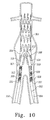
- Figure 10 shows an introducer containing an interconnected leg extension prosthesis during deployment within an aortic aneurysm.
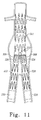
- Figure 11 shows a deployed prosthesis system with a bifurcated prosthesis deployed in the aorta and an interconnected leg extension prosthesis deployed into the iliac arteries.
- the present invention relates to an endoluminal prosthesis having leg extensions that are interconnected.
- the prosthesis includes two stent graft sections separated by a flexible bridge section.
- the stent graft sections are interconnected by the flexible bridge and can coordinate with a bifurcated prosthesis to form leg portions of an endoluminal prosthesis assembly.
- the prosthesis can be delivered through one iliac artery, into a main bifurcated prosthesis, and into the other iliac artery.
- distal with respect to a prosthesis is intended to refer to the end of the prosthesis furthest away in the direction of blood flow from the heart
- proximal is intended to mean the end of the prosthesis that, when implanted, would be nearest to the heart.
- prosthesis means any replacement for a body part or for a function of that body part; or any device that enhances or adds functionality to a physiological system.
- endoluminal describes objects that are found or can be placed inside a lumen or space in the human or animal body. This includes lumens such as blood vessels, parts of the gastrointestinal tract, ducts such as bile ducts, parts of the respiratory system, etc. "Endoluminal prosthesis” thus describes a prosthesis that can be placed inside one of these lumens.
- graft means a generally cannular or tubular member which acts as an artificial vessel.
- a graft by itself or with the addition of other elements can be an endoluminal prosthesis.
- stent means any device or structure that adds rigidity, expansion force or support to a prosthesis. Typically, a stent has a tubular shape when used for endoluminal applications.
- stent graft means a stent that has been sewn, sutured, or otherwise connected to graft material.
- partial stent means a stent that has does not form a complete tubular shape, and is typically configured as a stent that has been divided along its axis or parallel to its axis.
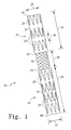
- an example of an interconnected leg extension prosthesis 20 contains two tubular stent graft sections 22 and 24 connected by a flexible bridge 40.
- Each stent graft section contains at least one stent 26 or 28 attached to a biocompatible graft material 32 or 34.
- Each stent graft section has a central opening 42 or 44 near the flexible bridge and a terminal opening 46 or 48 away from the flexible bridge at the ends of the prosthesis.
- Each end of the flexible bridge is irreversibly attached to one of the stent graft sections at a central opening.
- the graft material covering the stent or stents of each stent graft section is a biocompatible material.
- the biocompatible material is in the form of a fabric that is impermeable to liquids, including blood or other physiological fluids.
- biocompatible materials include polyesters, such as poly(ethylene terephthalate), and fluorinated polymers, such as polytetrafluoroethylene (PTFE) and expanded PTFE.
- PTFE polytetrafluoroethylene
- biocompatible polyesters include DACRON (DUPONT, Wilmington, DE) and TWILLWEAVE MICREL (VASCUTEK, Renfrewshire, Scotland).
- ECM extracellular matrix
- ECM materials include pericardium, stomach submucosa, liver basement membrane, urinary bladder submucosa, tissue mucosa, and dura mater.
- a specific example of an ECM material is small intestinal submucosa (SIS), such as is described in U.S. Patent No. 6,206,931 .
- the graft material may be made of a single material, or it may be a blend, weave, laminate or composite of two or more materials.
- the graft material may also include other additives, such as plasticizers, compatibilizers, surface modifiers, biological materials such as peptides and enzymes, and therapeutic agents such as drugs or other medicaments.
- the particular graft material on each stent graft section may be the same, or the materials may be different.
- a single piece of graft material may be used, such that a portion of graft material spans the distance between the central openings.
- the graft material for each stent graft section is secured to one or more stents.
- standard surgical suturing techniques can be used to secure the graft material to a stent.
- a stent can be positioned on the interior of the tubular graft material, or it can be positioned on the exterior of the graft material.
- a stent can also be secured to one of the openings of the tubular graft material such that the stent extends from the material.
- a stent extending from the graft material can be secured to the interior and/or the exterior of the material.
- a stent can be sandwiched between two layers of graft material, and this stent may also be secured by sutures. Examples of suture material include PROLENE ® (5-0).
- Stents may have a wide variety of configurations and may be balloon-expandable or self-expanding.
- stents typically have a circular cross-section when fully expanded, so as to conform to the generally circular cross-section of a body lumen.
- the stents used in the stent graft sections may be discrete stents having a zig-zag configuration in which straight struts are set at angles to each other and are connected by acute bends. The struts are thus connected into an endless loop, forming a generally tubular structure.
- Discrete zig-zag stents are also referred to as Gianturco stents or Z-stents.
- a specific example of a Z-stent is the Z-STENT available from COOK, INC. (Bloomington, IN).
- the stents may contain individual stent segments that are connected to provide an elongated, flexible stent.
- the individual stent segments can have a variety of configurations, including the zig-zag configuration.
- a specific example of a connected zig-zag stent is the ZILVER TM stent available from COOK, INC..
- Stents may be made of any rigid biocompatible material, such as metal, plastic or ceramic.
- the stents are made of a metal, such as stainless steel, nitinol, and other biocompatible alloys.
- Stents may be equipped with one or more barbs to secure the prosthesis to the vessel wall or to another component of the prosthesis. If the stent is secured to the graft material by suturing, the sutures may be positioned along struts and/or at bends within the stent. For stents having a zig-zag configuration, it may be desirable to employ two sutures at each bend of the stent to further increase the stability of the connection, as described in Australian Provisional Patent Application No. 2002950951 , which is incorporated herein by reference.
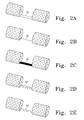
- the flexible bridge can have a variety of configurations and serves to retain the stent graft sections within a minimum distance of each other.
- the flexible bridge may be a piece of graft material 52 that is sutured to or integral with the graft materials of each of the stent graft sections.
- the flexible bridge is made of a material such as metal, plastic or ceramic such that it has some rigidity but can still be bent into an acute angle.
- the flexible bridge may be a portion of metal, plastic or ceramic configured as a wire 54 or a ribbon 56.
- a flexible bridge configured as a wire or ribbon may form a relatively linear connection between the stent graft sections, or may have a more flexible shape, such as a zig-zag (58) or sinusoidal (59) shape.
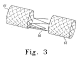
- the flexible bridge includes a portion of one or more stents having a curved cross-section.
- the flexible bridge 60 is configured as a partial Z-stent, that is a Z-stent that has been cleaved at one point so as not to form an endless loop of stent material.
- This partial Z-stent bridge is irreversibly attached to stent portions of stent graft sections 61 and 63.
- Portions of a wide variety of stent materials and configurations may be used as partial stents for the flexible bridge.
- Such partial stents preferably have a curved cross-section.
- the flexible bridge is irreversibly attached to the stent graft sections, and can be attached to the graft material and/or to a stent of the stent graft section.
- the term "irreversible attachment” means that the flexible bridge cannot be separated from the stent graft section under a normal use environment without damaging or destroying either of the two components.
- a variety of irreversible attachments can be used.
- the flexible bridge 70 can be irreversibly attached to the stent graft 64 by suturing an end of the bridge to the graft material 66 ( Figure 4A ).
- the flexible bridge 72 can be irreversibly attached to the stent graft 64 by suturing the bridge to a length of graft material 73 that is irreversibly attached to the graft material 66 of the stent graft section ( Figure 4B ).
- the flexible bridge 74 can be irreversibly attached to a stent 68 of the stent graft 64 ( Figure 4C ).
- the flexible bridge is attached to the stent of the stent graft section.
- the flexible bridge may be integral with one or both stents. That is, the flexible bridge and one or both stents may be formed from a single piece of material.
- the flexible bridge may be a separate piece of material that has been affixed to one or both stents by any of a variety of methods including welding, brazing, and soldering.
- the flexible bridge is a partial stent having a curved cross-section and irreversibly attached to each of the stents located at the central openings.
- the flexible bridge is made of a metal, such as stainless steel, nitinol, and other alloys.
- the flexible bridge is a partial zig-zag stent and is integral with both of the stents located at the central openings, each of which are also zig-zag stents.
- the flexible bridge is a partial stent that is a portion of a connected zig-zag stent.
- the flexible bridge is integral with each internal stent located at the central opening of each of the stent graft sections.
- internal stents 50 and 51 and the partial stent of the flexible bridge 53 are an integral portion of a single connected zig-zag stent.
- the internal stents are covered with graft material 55 and 57.
- the stent graft sections 65 and 67 may each have additional Z-stents 62 away from the central openings, and these stents may be internal or external.
- internal stents 75 and 76 are covered with graft material 55 and 57, and extend from the cental opening to the terminal opening of their respective stent graft sections 78 and 79.
- These internal stents and the partial stent of the flexible bridge 77 are an integral portion of a single connected zig-zag stent.
- each section of the interconnected leg extension prosthesis, and each component of the prosthesis assembly of which the interconnected leg extension prosthesis is a component is precisely constructed so as to provide the optimum fit of the prosthesis assembly with the vasculature to be treated.
- the dimensions of the vasculature may be determined by a variety of methods, including intraoperative intravascular ultrasound (IVUS) and radiologic studies such as computerized tomography (CT), magnetic resonance imaging (MRI), angiography.
- Interconnected prostheses may also be constructed so as to have a range of discrete sizes. In this way, the interconnected leg extension prosthesis can be kept in stock for use with other stock components for emergency treatments. This general type of system is described, for example in U.S. Patent Application Publication 2002/0198587 A1 .
- interconnected leg extension prothesis is as a component of a prosthesis assembly for treatment of an aortic aneurysm.
- Such an assembly could include the interconnected leg extension prosthesis and a bifurcated prosthesis having a main tubular body with a proximal opening and two distal openings.
- the main tubular body of the bifurcated prosthesis is intended to attach to the healthy tissue above the aneurysm near the proximal opening of the prosthesis.
- the two openings at the distal end of the main tubular body form the bifurcation that fits over the iliac bifurcation such that each distal opening is at or within one of the iliac branch arteries.
- An example of such a bifurcated prosthesis is described in WO98/53761 .
- the desired dimensions of an interconnected leg extension prosthesis are determined by the dimensions and condition (i.e. healthy or aneurysmal) of the iliac arteries and by the dimensions of the bifurcated prosthesis with which the leg extensions will coordinate.
- the diameter 30 or 31 of a stent graft section will typically range from 8 mm to 24 mm, and the length 35 or 36 will typically range from 15 mm to 125 mm.
- the distance 38 between the central openings of the stent graft sections in this example will typically range from 30 mm to 60 mm.
- the spacing 39 of the stents along the axis of the stent graft is preferably from 0 mm to 8 mm.
- bifurcated prosthesis 100 for treatment of aortic aneurysms is the ZENITH TM AAA prosthesis system available from COOK, INC., which is generally described in WO98/53761 .
- this type of bifurcated prosthesis 100 has a main tubular body 102 with a proximal opening 104 and having two distal tubular legs 106 and 108 at the bifurcation 110.
- a stent 112 is attached to and extends from the graft material near the proximal opening 104. This stent contains barbs 114 to provide for anchoring of the prosthesis above the aneurysm.
- the longer distal leg 106 is typically deployed in the ipsilateral iliac artery, and the shorter distal leg 108 is typically deployed in the contralateral iliac artery.
- the shorter leg contains one external zig-zag stent 111 between the bifurcation and the distal opening 109, and the longer leg contains two external zig-zag stents 111 between the bifurcation and the distal opening 107.
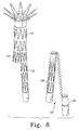
- FIG. 7 An example of an interconnected leg extension prosthesis 80 for use specifically with the bifurcated prosthesis of Figure 6 is shown in Figure 7 .
- This example has a longer stent graft section 81 and a shorter stent graft section 82. These stent graft sections are designed to engage with the shorter and longer legs of the bifurcated prosthesis, respectively.
- the longer stent graft section contains an internal stent 83 near the central opening 85 and contains three external stents 84 along the length of the section.
- the shorter stent graft section contains an internal stent 86 near the central opening 88 and contains two external stents 87 along the length of the section.
- each stent graft section can contain either an internal stent or an external stent. Internal stents are preferred for the terminal ends of the stent graft sections, as this may provide for enhanced sealing between the vessel wall and the prosthesis.
- the flexible bridge 95 is shown in a bent form to illustrate a possible configuration of the prosthesis when deployed at the site of treatment.
- the flexible bridge is irreversibly attached to each of the internal stents at the central openings. When deployed, these central openings function as the proximal openings for each of the stent graft sections and are intended to coordinate with the distal openings of the bifurcated prosthesis.
- a bifurcated prosthesis 150 has a longer distal leg 156 and a shorter distal leg 158.
- An interconnected leg extension prosthesis 160 for use with this bifurcated prosthesis can have a shorter stent graft section 166 and a longer stent graft section 168.
- the shorter stent graft section contains at least an internal stent at the central opening and another internal stent at the terminal opening.
- An interconnected leg extension prosthesis 80 as shown in Figure 7 can also be used with bifurcated prosthesis 150, depending on the treatment requirements.
- An interconnected leg extension prosthesis can be delivered to a treatment site using a variety of endovascular techniques.
- a catheter-based introducer can be used to insert a compressed prosthesis into the body through a femoral artery and then into the aorta.
- the introducer may be similar to those described in WO 03/53761 and in US2002/0198587 .
- an example of an introducer 200 for an interconnected leg extension prosthesis 201 includes a delivery sheath 202, tapered dilator 204 at proximal end 206, and a fitting 208 at distal end 210 of the delivery system.
- Inner cannula 214 which is connected to handle 216, extends completely from the tapered dilator 204 to distal end 210.
- Joined to the side of fitting 208 is an injection system 212, for saturating the prosthesis with anticoagulant heparin or other agents prior to deployment, and optionally for the injection of contrast medium or other agents after deployment.
- the introducer 200 also includes check-flow valve 226, pusher 228, pusher fitting 230 and pin vise 232, all of which are covered with a protective tube 234.
- the protective tube 234 covers the distal end components during handling and is removed prior to use.
- Tabs 220 are provided at the distal end of short sheath 222, for peeling away the sheath prior to use. Sheath 222 protects the patency of the introducer lumen at the check-flow valve during shipping and handling, and extends only into fitting 208.
- Stylet 224 extends through cannula 214, through pusher 228 and introducer sheath 202 to a proximal tip 205 that protrudes from the proximal end of the tapered dilator 204. Stylet 224 is also of protective value during shipping and handling and is likewise removed prior to use in the medical procedure.
- delivery system 300 is introduced into the patient in delivery sheath 302 by insertion through ipsilateral iliac artery 350 and into the distal opening 307 of a bifurcated prosthesis 301 that has been deployed in the main aorta.
- the inner cannula is then bent at an acute angle to direct the dilator 304 down the contralateral artery 351 and past the other distal opening 309 of the bifurcated prosthesis.
- the compressed central opening 324 of stent graft section 320 is within the distal portion of leg 308, the compressed central opening 326 of stent graft section 322 is within distal portion of leg 306, and the flexible bridge 332 is bent at an acute angle.
- the delivery sheath 302 can then be pulled back towards the distal end of the delivery system, sequentially releasing the terminal opening 328 and the central opening 324 of stent graft section 320, the flexible bridge 332, and the central opening 326 and the terminal opening 330 of stent graft section 322.
- each stent graft section of the prosthesis self-expands and may press against the inner surface of the bifurcated prosthesis or against the vessel wall of the iliac artery.
- the central opening portions 324 and 326 expand against the distal portions of legs 306 and 308, establishing a friction fit between the stent graft sections and the bifurcated prosthesis.
- the stent graft sections 320 and 322 function as leg extensions for the prosthesis assembly, and central openings 324 and 326 function as the proximal ends of the legs.
- the terminal openings 328 and 330 engage the vessel wall in the iliac arteries and function as the distal ends of the legs.
- the attachment of the prosthesis at the implantation site and its sealing engagement to the bifurcated prosthesis and to the vessel walls may be further enhanced by inflating a molding balloon at each site to fully expand the prosthesis to press against the bifurcated prosthesis and/or the vessel wall.
- the flexible bridge is bent over the bifurcation within the main prosthesis, and the graft material of each stent graft section overlaps with the graft material of the main prosthesis. Delivery of the complete prosthesis assembly is simplified since both leg extensions are part of a single interconnected component. In addition, this prosthesis system provides a reduced risk of leg extension separation due to the counterbalancing of forces on the two iliac leg stent grafts.
Abstract
Description
- This Invention relates to prostheses for implantation within the human or animal body for the repair of damaged lumens such as blood vessels.
- the functional vessels of human and animal bodies, such as blood vessels and ducts, occasionally weaken or even rupture. For example, in the aortic artery, the vascular wall can weaken or tear, resulting in dangerous conditions such as aneurysm and dissection. Treatment of such conditions can be performed by implanting a prosthesis within the vascular system using minimally invasive surgical procedures. An endoluminal prosthesis typically includes one or more stents affixed to graft material and is delivered to the treatment site by endovascular insertion. Once the endoluminal prosthesis is radially enlarged, it should remain in place indefinitely by self-attachment to the vessel wall, acting as a substitute vessel for the flow of blood or other fluids.
- Treatment of vascular conditions near a branch point with an endoluminal prosthesis can present a number of difficulties. A single, straight section of a tubular prosthesis may not be able to span the aneurysm or dissection and still maintain sufficient contact with healthy vascular tissue to secure the prosthesis and to prevent endoleaks, For example, most abdominal aortic aneurysms occur at or near the iliac bifurcation, and treatment with an endoluminal prosthesis requires the presence of prosthesis material in the main aorta and in the iliac branch arteries (Dietrich, E. B. J. Invasive Cardiol. 13 (5): 383-390,2001). Typically, an endoluminal prosthesis for use near a bifurcation will have a main lumen body, for placement within the aorta, and two branch lumens extending from the main lumen body into the branch arteries.
- A simple approach to bifurcated prostheses from a materials perspective is to use a single piece prosthesis. Such unitary structures have a main tubular body and pre-formed leg extensions. The seamless structure provided by this configuration can minimize the probability of leakage within the prosthesis. However, the constrained geometry of branched vasculature makes it extremely difficult to deliver such a large structure to the treatment site. For example, in treating aortic aneurysms, the deployment of a leg extension down the contralateral iliac artery is especially problematic.
- A more common alternative to the single piece approach is the use of a modular system. In these systems, one or both of the leg extensions can be attached to a main tubular body to provide the final prosthesis. Examples of modular systems are described in
PCT Patent Application Publication WO98/53761 U. S. Patent Application Publication 2002/0198587 A1 Although the delivery of modular systems is less difficult due to the smaller sizes of the individual components, it can still be a complex and time-consuming process to make the precise connections between the body and one or both legs. The difficulty and risk of the treatment procedure can also increase when there are more Individual parts to insert, align, and deploy. Possible complications with modular systems include the occurrence of endoleaks, due to imperfect seals between the body and a leg component, and the separation of the legs from the main prosthesis body over time. - In one aspect of the invention, there Is provided an endoluminal prosthesis assembly, comprising: a bifurcated prosthesis comprising a main tubular body having a single proximal opening and first and second distal tubular legs at a bifurcation, the first leg having a first distal opening, and the second leg having a second distal opening, and an extension prosthesis comprising a first stent graft, a second stent graft, and a flexible bridge extending between the first and second stent grafts and connected to the first and second stent grafts along a part of the circumference of an end of each of said first and second stent grafts, wherein the first stent graft is sized and configured to engage the second distal opening and the second stent graft is sized and configured to engage the first distal opening and wherein the flexible bridge is bendable over the bifurcation of the main tubular body so that the first and second stent graft function as leg extensions for the bifurcated prosthesis.
- These aspects may further include an endoluminal prosthesis assembly wherein the bifurcated stent graft comprises a self-expanding stent attached to and extending from the proximal opening; wherein the bifurcated stent graft comprises a shorter stent graft leg between the main tubular body and one of the distal openings and a longer stent graft leg between the main tubular body and the other distal opening; and wherein the first stent graft is longer than the second stent graft, and wherein the first stent graft is sized and configured to engage the distal opening of the shorter stent graft leg and the second stent graft is sized and configured to engage the distal opening of the longer stent graft leg.
-
Figure 1 shows an interconnected leg extension prosthesis. -
Figures 2A-2E show examples of interconnected leg extension prostheses having varying flexible bridge configurations. -
Figure 3 shows a flexible bridge configured as a partial stent. -
Figures 4A - 4C show examples of irreversible attachments between a flexible bridge and stent graft sections. -
Figures 5A - 5B show examples of interconnected leg extension prostheses having internal stents and a flexible bridge that are an integral portion of a connected zig-zag stent. -
Figure 6 shows a bifurcated prosthesis for treatment of aortic aneurysms. -
Figure 7 shows an interconnected leg extension prosthesis for use with the bifurcated prosthesis ofFigure 6 . -
Figure 8 shows an example of a prosthesis system with a bifurcated prosthesis and an interconnected leg extension prosthesis. -
Figure 9 shows an introducer for use with an interconnected leg extension prosthesis. -
Figure 10 shows an introducer containing an interconnected leg extension prosthesis during deployment within an aortic aneurysm. -
Figure 11 shows a deployed prosthesis system with a bifurcated prosthesis deployed in the aorta and an interconnected leg extension prosthesis deployed into the iliac arteries. - The present invention relates to an endoluminal prosthesis having leg extensions that are interconnected. The prosthesis includes two stent graft sections separated by a flexible bridge section. The stent graft sections are interconnected by the flexible bridge and can coordinate with a bifurcated prosthesis to form leg portions of an endoluminal prosthesis assembly. In the treatment of an aortic aneurysm, the prosthesis can be delivered through one iliac artery, into a main bifurcated prosthesis, and into the other iliac artery.
- Throughout this specification, when discussing the application of this invention to the aorta, the term distal with respect to a prosthesis is intended to refer to the end of the prosthesis furthest away in the direction of blood flow from the heart, and the term proximal is intended to mean the end of the prosthesis that, when implanted, would be nearest to the heart.
- The term "prosthesis" means any replacement for a body part or for a function of that body part; or any device that enhances or adds functionality to a physiological system.
- The term "endoluminal" describes objects that are found or can be placed inside a lumen or space in the human or animal body. This includes lumens such as blood vessels, parts of the gastrointestinal tract, ducts such as bile ducts, parts of the respiratory system, etc. "Endoluminal prosthesis" thus describes a prosthesis that can be placed inside one of these lumens.
- The term "graft" means a generally cannular or tubular member which acts as an artificial vessel. A graft by itself or with the addition of other elements can be an endoluminal prosthesis.
- The term "stent" means any device or structure that adds rigidity, expansion force or support to a prosthesis. Typically, a stent has a tubular shape when used for endoluminal applications. The term "stent graft" means a stent that has been sewn, sutured, or otherwise connected to graft material. The term "partial stent" means a stent that has does not form a complete tubular shape, and is typically configured as a stent that has been divided along its axis or parallel to its axis.
- Referring to
Figure 1 , an example of an interconnectedleg extension prosthesis 20 contains two tubularstent graft sections 22 and 24 connected by aflexible bridge 40. Each stent graft section contains at least onestent biocompatible graft material central opening - The graft material covering the stent or stents of each stent graft section is a biocompatible material. Preferably the biocompatible material is in the form of a fabric that is impermeable to liquids, including blood or other physiological fluids. Examples of biocompatible materials include polyesters, such as poly(ethylene terephthalate), and fluorinated polymers, such as polytetrafluoroethylene (PTFE) and expanded PTFE. Examples of biocompatible polyesters include DACRON (DUPONT, Wilmington, DE) and TWILLWEAVE MICREL (VASCUTEK, Renfrewshire, Scotland). Examples of biocompatible materials also include extracellular matrix (ECM) materials, such as a purified collagen-based matrix derived from submucosa tissue. Examples of ECM materials include pericardium, stomach submucosa, liver basement membrane, urinary bladder submucosa, tissue mucosa, and dura mater. A specific example of an ECM material is small intestinal submucosa (SIS), such as is described in
U.S. Patent No. 6,206,931 . - The graft material may be made of a single material, or it may be a blend, weave, laminate or composite of two or more materials. The graft material may also include other additives, such as plasticizers, compatibilizers, surface modifiers, biological materials such as peptides and enzymes, and therapeutic agents such as drugs or other medicaments. The particular graft material on each stent graft section may be the same, or the materials may be different. A single piece of graft material may be used, such that a portion of graft material spans the distance between the central openings.
- The graft material for each stent graft section is secured to one or more stents. For example, standard surgical suturing techniques can be used to secure the graft material to a stent. A stent can be positioned on the interior of the tubular graft material, or it can be positioned on the exterior of the graft material. A stent can also be secured to one of the openings of the tubular graft material such that the stent extends from the material. A stent extending from the graft material can be secured to the interior and/or the exterior of the material. In another example, a stent can be sandwiched between two layers of graft material, and this stent may also be secured by sutures. Examples of suture material include PROLENE® (5-0).
- Stents may have a wide variety of configurations and may be balloon-expandable or self-expanding. Typically, stents have a circular cross-section when fully expanded, so as to conform to the generally circular cross-section of a body lumen. For example, the stents used in the stent graft sections may be discrete stents having a zig-zag configuration in which straight struts are set at angles to each other and are connected by acute bends. The struts are thus connected into an endless loop, forming a generally tubular structure. Discrete zig-zag stents are also referred to as Gianturco stents or Z-stents. A specific example of a Z-stent is the Z-STENT available from COOK, INC. (Bloomington, IN). In another example, the stents may contain individual stent segments that are connected to provide an elongated, flexible stent. The individual stent segments can have a variety of configurations, including the zig-zag configuration. A specific example of a connected zig-zag stent is the ZILVER™ stent available from COOK, INC..
- Stents may be made of any rigid biocompatible material, such as metal, plastic or ceramic. Preferably the stents are made of a metal, such as stainless steel, nitinol, and other biocompatible alloys. Stents may be equipped with one or more barbs to secure the prosthesis to the vessel wall or to another component of the prosthesis. If the stent is secured to the graft material by suturing, the sutures may be positioned along struts and/or at bends within the stent. For stents having a zig-zag configuration, it may be desirable to employ two sutures at each bend of the stent to further increase the stability of the connection, as described in Australian Provisional Patent Application No.
2002950951 - The flexible bridge can have a variety of configurations and serves to retain the stent graft sections within a minimum distance of each other. Referring to
Figure 2A , the flexible bridge may be a piece ofgraft material 52 that is sutured to or integral with the graft materials of each of the stent graft sections. Preferably the flexible bridge is made of a material such as metal, plastic or ceramic such that it has some rigidity but can still be bent into an acute angle. For example, referring toFigures 2B and 2C , the flexible bridge may be a portion of metal, plastic or ceramic configured as awire 54 or aribbon 56. Referring toFigures 2B through 2E , a flexible bridge configured as a wire or ribbon may form a relatively linear connection between the stent graft sections, or may have a more flexible shape, such as a zig-zag (58) or sinusoidal (59) shape. - In another example, the flexible bridge includes a portion of one or more stents having a curved cross-section. Referring to
Figure 3 , in a specific example theflexible bridge 60 is configured as a partial Z-stent, that is a Z-stent that has been cleaved at one point so as not to form an endless loop of stent material. This partial Z-stent bridge is irreversibly attached to stent portions ofstent graft sections - The flexible bridge is irreversibly attached to the stent graft sections, and can be attached to the graft material and/or to a stent of the stent graft section. The term "irreversible attachment" means that the flexible bridge cannot be separated from the stent graft section under a normal use environment without damaging or destroying either of the two components. A variety of irreversible attachments can be used. For example, the
flexible bridge 70 can be irreversibly attached to thestent graft 64 by suturing an end of the bridge to the graft material 66 (Figure 4A ). In another example, theflexible bridge 72 can be irreversibly attached to thestent graft 64 by suturing the bridge to a length ofgraft material 73 that is irreversibly attached to thegraft material 66 of the stent graft section (Figure 4B ). In yet another example, theflexible bridge 74 can be irreversibly attached to astent 68 of the stent graft 64 (Figure 4C ). Preferably, the flexible bridge is attached to the stent of the stent graft section. The flexible bridge may be integral with one or both stents. That is, the flexible bridge and one or both stents may be formed from a single piece of material. The flexible bridge may be a separate piece of material that has been affixed to one or both stents by any of a variety of methods including welding, brazing, and soldering. - Preferably, the flexible bridge is a partial stent having a curved cross-section and irreversibly attached to each of the stents located at the central openings. Preferably the flexible bridge is made of a metal, such as stainless steel, nitinol, and other alloys. In a preferred configuration, the flexible bridge is a partial zig-zag stent and is integral with both of the stents located at the central openings, each of which are also zig-zag stents.
- In another example, the flexible bridge is a partial stent that is a portion of a connected zig-zag stent. In this example, the flexible bridge is integral with each internal stent located at the central opening of each of the stent graft sections. Referring to
Figure 5A ,internal stents flexible bridge 53 are an integral portion of a single connected zig-zag stent. The internal stents are covered withgraft material stent graft sections stents 62 away from the central openings, and these stents may be internal or external. Referring toFigure 5B ,internal stents graft material stent graft sections flexible bridge 77 are an integral portion of a single connected zig-zag stent. - The dimensions of the flexible bridge and each of the stent graft sections are determined by the intended use of the prosthesis. Ideally, each section of the interconnected leg extension prosthesis, and each component of the prosthesis assembly of which the interconnected leg extension prosthesis is a component, is precisely constructed so as to provide the optimum fit of the prosthesis assembly with the vasculature to be treated. The dimensions of the vasculature may be determined by a variety of methods, including intraoperative intravascular ultrasound (IVUS) and radiologic studies such as computerized tomography (CT), magnetic resonance imaging (MRI), angiography. Interconnected prostheses may also be constructed so as to have a range of discrete sizes. In this way, the interconnected leg extension prosthesis can be kept in stock for use with other stock components for emergency treatments. This general type of system is described, for example in
U.S. Patent Application Publication 2002/0198587 A1 . - One of the possible uses of the interconnected leg extension prothesis is as a component of a prosthesis assembly for treatment of an aortic aneurysm. Such an assembly could include the interconnected leg extension prosthesis and a bifurcated prosthesis having a main tubular body with a proximal opening and two distal openings. The main tubular body of the bifurcated prosthesis is intended to attach to the healthy tissue above the aneurysm near the proximal opening of the prosthesis. The two openings at the distal end of the main tubular body form the bifurcation that fits over the iliac bifurcation such that each distal opening is at or within one of the iliac branch arteries. An example of such a bifurcated prosthesis is described in
WO98/53761 - In the treatment of aortic aneurysms, the desired dimensions of an interconnected leg extension prosthesis are determined by the dimensions and condition (i.e. healthy or aneurysmal) of the iliac arteries and by the dimensions of the bifurcated prosthesis with which the leg extensions will coordinate. Referring again to
Figure 1 , in this example thediameter length distance 38 between the central openings of the stent graft sections in this example will typically range from 30 mm to 60 mm. For a stent graft section containing two or more discrete stents or stent segments, the spacing 39 of the stents along the axis of the stent graft is preferably from 0 mm to 8 mm. - One specific example of a bifurcated prosthesis for treatment of aortic aneurysms is the ZENITH™ AAA prosthesis system available from COOK, INC., which is generally described in
WO98/53761 Figure 6 , this type ofbifurcated prosthesis 100 has a maintubular body 102 with aproximal opening 104 and having two distaltubular legs bifurcation 110. Astent 112 is attached to and extends from the graft material near theproximal opening 104. This stent containsbarbs 114 to provide for anchoring of the prosthesis above the aneurysm. The longerdistal leg 106 is typically deployed in the ipsilateral iliac artery, and the shorterdistal leg 108 is typically deployed in the contralateral iliac artery. The shorter leg contains one external zig-zag stent 111 between the bifurcation and thedistal opening 109, and the longer leg contains two external zig-zag stents 111 between the bifurcation and thedistal opening 107. - An example of an interconnected
leg extension prosthesis 80 for use specifically with the bifurcated prosthesis ofFigure 6 is shown inFigure 7 . This example has a longerstent graft section 81 and a shorterstent graft section 82. These stent graft sections are designed to engage with the shorter and longer legs of the bifurcated prosthesis, respectively. The longer stent graft section contains aninternal stent 83 near thecentral opening 85 and contains threeexternal stents 84 along the length of the section. The shorter stent graft section contains aninternal stent 86 near thecentral opening 88 and contains twoexternal stents 87 along the length of the section. Theterminal end - Referring still to
Figure 7 , theflexible bridge 95 is shown in a bent form to illustrate a possible configuration of the prosthesis when deployed at the site of treatment. The flexible bridge is irreversibly attached to each of the internal stents at the central openings. When deployed, these central openings function as the proximal openings for each of the stent graft sections and are intended to coordinate with the distal openings of the bifurcated prosthesis. - The length of the stent graft sections and the number of stents contained within the sections can vary independently. For example, referring to
Figure 8 , abifurcated prosthesis 150 has a longerdistal leg 156 and a shorterdistal leg 158. An interconnectedleg extension prosthesis 160 for use with this bifurcated prosthesis can have a shorterstent graft section 166 and a longerstent graft section 168. Preferably the shorter stent graft section contains at least an internal stent at the central opening and another internal stent at the terminal opening. An interconnectedleg extension prosthesis 80 as shown inFigure 7 can also be used withbifurcated prosthesis 150, depending on the treatment requirements. - An interconnected leg extension prosthesis can be delivered to a treatment site using a variety of endovascular techniques. In treating aortic aneurysms, a catheter-based introducer can be used to insert a compressed prosthesis into the body through a femoral artery and then into the aorta. The introducer may be similar to those described in
WO 03/53761 US2002/0198587 . - Referring to
Figure 9 , an example of anintroducer 200 for an interconnectedleg extension prosthesis 201 includes adelivery sheath 202, tapereddilator 204 atproximal end 206, and a fitting 208 atdistal end 210 of the delivery system.Inner cannula 214, which is connected to handle 216, extends completely from the tapereddilator 204 todistal end 210. Joined to the side of fitting 208 is aninjection system 212, for saturating the prosthesis with anticoagulant heparin or other agents prior to deployment, and optionally for the injection of contrast medium or other agents after deployment. - Referring still to
Figure 9 , theintroducer 200 also includes check-flow valve 226,pusher 228, pusher fitting 230 andpin vise 232, all of which are covered with aprotective tube 234. Theprotective tube 234 covers the distal end components during handling and is removed prior to use.Tabs 220 are provided at the distal end ofshort sheath 222, for peeling away the sheath prior to use.Sheath 222 protects the patency of the introducer lumen at the check-flow valve during shipping and handling, and extends only intofitting 208.Stylet 224 extends throughcannula 214, throughpusher 228 andintroducer sheath 202 to aproximal tip 205 that protrudes from the proximal end of the tapereddilator 204.Stylet 224 is also of protective value during shipping and handling and is likewise removed prior to use in the medical procedure. - Referring to the cutaway view of
Figure 10 ,delivery system 300 is introduced into the patient indelivery sheath 302 by insertion through ipsilateraliliac artery 350 and into thedistal opening 307 of abifurcated prosthesis 301 that has been deployed in the main aorta. The inner cannula is then bent at an acute angle to direct thedilator 304 down thecontralateral artery 351 and past the otherdistal opening 309 of the bifurcated prosthesis. At this point, the compressedcentral opening 324 ofstent graft section 320 is within the distal portion ofleg 308, the compressedcentral opening 326 ofstent graft section 322 is within distal portion ofleg 306, and theflexible bridge 332 is bent at an acute angle. Thedelivery sheath 302 can then be pulled back towards the distal end of the delivery system, sequentially releasing theterminal opening 328 and thecentral opening 324 ofstent graft section 320, theflexible bridge 332, and thecentral opening 326 and theterminal opening 330 ofstent graft section 322. - Referring to
Figure 11 , as each stent graft section of the prosthesis is released, that section self-expands and may press against the inner surface of the bifurcated prosthesis or against the vessel wall of the iliac artery. Thecentral opening portions legs stent graft sections central openings terminal openings - As is evident from
Figure 11 , the flexible bridge is bent over the bifurcation within the main prosthesis, and the graft material of each stent graft section overlaps with the graft material of the main prosthesis. Delivery of the complete prosthesis assembly is simplified since both leg extensions are part of a single interconnected component. In addition, this prosthesis system provides a reduced risk of leg extension separation due to the counterbalancing of forces on the two iliac leg stent grafts.
Claims (14)
- An endoluminal prosthesis assembly, comprising: a bifurcated prosthesis (150) comprising a main tubular body (102) having a single proximal opening (104) and first and second distal tubular legs (106, 108) at a bifurcation (110), the first leg having a first distal opening (107), and the second leg (106) having a second distal opening (109), and an extension prosthesis (160) comprising a first stent graft (81), a second stent graft (82), and a flexible bridge (95) extending between the first and second stent grafts and connected to the first and second stent grafts (81, 82) along a part of the circumference of an end of each of said first and second stent grafts, wherein the first stent graft (81) is sized and configured to engage the second distal opening (109) and the second stent graft is sized and configured to engage the first distal opening (107) and wherein the flexible bridge is bendable over the bifurcation of the main tubular body so that the first and second stent graft function as leg extensions for the bifurcated prosthesis.
- The endoluminal prosthesis assembly of claim 1, wherein the flexible bridge (95) is irreversibly attached to the first and second stent grafts.
- The endoluminal prosthesis assembly of claim 1 or 2, wherein the bifurcated prosthesis (100) comprises a self-expanding stent attached to and extending from the proximal opening.
- The endoluminal prosthesis assembly of any one of claims 1 to 3, wherein the bifurcated prosthesis (100) comprises a shorter stent graft leg (108) between the main tubular body and one of the distal openings and a longer stent graft leg (106) between the main tubular body and the other distal opening.
- The endoluminal prosthesis assembly of claim 4, wherein the first stent graft (81) Is longer than the second stent graft (82), and wherein the first stent graft is sized and configured to engage the distal opening of the shorter stent graft leg and the second stent graft is sized and configured to engage the distal opening of the longer stent graft leg.
- The endoluminal prosthesis assembly of claim 1 or 2, wherein the first stent graft (22) comprises a plurality of self-expanding stents.
- The endoluminal prosthesis assembly of claim 6, wherein the second stent graft (24) comprises a plurality of self-expanding stents.
- The endoluminal prosthesis assembly of any preceding claim, wherein the flexible bridge (40) comprises a wire.
- The endoluminal prosthesis assembly of claim 1 or 2, wherein the flexible bridge (40) comprises a partial stent extending partially around the circumferences of the first and second stent grafts (22, 24).
- The endoluminal prosthesis assembly of any preceding claim, wherein the first and second stent grafts (22, 24) each comprise a stent adjacent the flexible bridge (40), and the flexible bridge (40) is integral with at least one of the stents.
- The endoluminal prosthesis assembly of claim 1 or 2, wherein the first and second stent grafts (22, 24) each comprise a stent affixed to the flexible bridge (40).
- The endoluminal prosthesis assembly of any preceding claim, wherein the first stent graft (22) and the second stent graft (24) each comprise a central opening (42, 44) and a terminal opening (46, 48), the central openings adjacent to and on opposite ends of the flexible bridge (40); and the central and terminal openings each comprising an internal stent.
- The endoluminal prosthesis assembly of claim 12, wherein the first stent graft (22) further comprises at least one external stent between the central opening and the terminal opening.
- The endoluminal prosthesis assembly of claim 13, wherein the second stent graft (24) further comprises at least one external stent between the central opening and the terminal opening.
Applications Claiming Priority (2)
| Application Number | Priority Date | Filing Date | Title |
|---|---|---|---|
| US53038803P | 2003-12-17 | 2003-12-17 | |
| PCT/US2004/042298 WO2005058202A1 (en) | 2003-12-17 | 2004-12-16 | Interconnected leg extensions for an endoluminal prostehsis |
Publications (2)
| Publication Number | Publication Date |
|---|---|
| EP1696828A1 EP1696828A1 (en) | 2006-09-06 |
| EP1696828B1 true EP1696828B1 (en) | 2010-08-25 |
Family
ID=34700132
Family Applications (1)
| Application Number | Title | Priority Date | Filing Date |
|---|---|---|---|
| EP04814477A Active EP1696828B1 (en) | 2003-12-17 | 2004-12-16 | Interconnected leg extensions for an endoluminal prostehsis |
Country Status (7)
| Country | Link |
|---|---|
| US (1) | US8257430B2 (en) |
| EP (1) | EP1696828B1 (en) |
| JP (1) | JP4464972B2 (en) |
| AT (1) | ATE478629T1 (en) |
| AU (1) | AU2004299108B2 (en) |
| DE (1) | DE602004028863D1 (en) |
| WO (1) | WO2005058202A1 (en) |
Families Citing this family (73)
| Publication number | Priority date | Publication date | Assignee | Title |
|---|---|---|---|---|
| US20060122691A1 (en) * | 1998-12-03 | 2006-06-08 | Jacob Richter | Hybrid stent |
| US8382821B2 (en) | 1998-12-03 | 2013-02-26 | Medinol Ltd. | Helical hybrid stent |
| US20040267349A1 (en) | 2003-06-27 | 2004-12-30 | Kobi Richter | Amorphous metal alloy medical devices |
| US8038708B2 (en) | 2001-02-05 | 2011-10-18 | Cook Medical Technologies Llc | Implantable device with remodelable material and covering material |
| US7147661B2 (en) | 2001-12-20 | 2006-12-12 | Boston Scientific Santa Rosa Corp. | Radially expandable stent |
| US9155639B2 (en) | 2009-04-22 | 2015-10-13 | Medinol Ltd. | Helical hybrid stent |
| US9039755B2 (en) | 2003-06-27 | 2015-05-26 | Medinol Ltd. | Helical hybrid stent |
| US20070198078A1 (en) | 2003-09-03 | 2007-08-23 | Bolton Medical, Inc. | Delivery system and method for self-centering a Proximal end of a stent graft |
| US11259945B2 (en) | 2003-09-03 | 2022-03-01 | Bolton Medical, Inc. | Dual capture device for stent graft delivery system and method for capturing a stent graft |
| US7763063B2 (en) | 2003-09-03 | 2010-07-27 | Bolton Medical, Inc. | Self-aligning stent graft delivery system, kit, and method |
| US8500792B2 (en) | 2003-09-03 | 2013-08-06 | Bolton Medical, Inc. | Dual capture device for stent graft delivery system and method for capturing a stent graft |
| US11596537B2 (en) | 2003-09-03 | 2023-03-07 | Bolton Medical, Inc. | Delivery system and method for self-centering a proximal end of a stent graft |
| US8292943B2 (en) | 2003-09-03 | 2012-10-23 | Bolton Medical, Inc. | Stent graft with longitudinal support member |
| US20080264102A1 (en) * | 2004-02-23 | 2008-10-30 | Bolton Medical, Inc. | Sheath Capture Device for Stent Graft Delivery System and Method for Operating Same |
| US9198786B2 (en) | 2003-09-03 | 2015-12-01 | Bolton Medical, Inc. | Lumen repair device with capture structure |
| WO2005067817A1 (en) | 2004-01-13 | 2005-07-28 | Remon Medical Technologies Ltd | Devices for fixing a sensor in a body lumen |
| US7674284B2 (en) * | 2004-03-31 | 2010-03-09 | Cook Incorporated | Endoluminal graft |
| KR100601969B1 (en) * | 2004-06-15 | 2006-07-14 | 주식회사 에스앤지바이오텍 | Artificial blood vessel stent |
| US10390714B2 (en) | 2005-01-12 | 2019-08-27 | Remon Medical Technologies, Ltd. | Devices for fixing a sensor in a lumen |
| EP1906878B1 (en) * | 2005-07-07 | 2015-08-19 | Cook Medical Technologies LLC | Branch vessel stent graft |
| US20100070043A1 (en) * | 2005-08-04 | 2010-03-18 | Kitchen Michael S | Shape memory orthopedic joint |
| GB0517085D0 (en) * | 2005-08-19 | 2005-09-28 | Angiomed Ag | Polymer prosthesis |
| WO2007040249A1 (en) * | 2005-10-06 | 2007-04-12 | Kaneka Corporation | Stent to be placed in the living body |
| US7670369B2 (en) * | 2005-10-13 | 2010-03-02 | Cook Incorporated | Endoluminal prosthesis |
| US20070106375A1 (en) * | 2005-11-07 | 2007-05-10 | Carlos Vonderwalde | Bifurcated stent assembly |
| EP1948007A1 (en) * | 2005-11-15 | 2008-07-30 | Remon Medical Technologies Ltd. | Implant device for fixing a sensor in a body lumen |
| US8840657B2 (en) * | 2006-01-18 | 2014-09-23 | Cook Medical Technologies Llc | Self expanding stent |
| JP5042244B2 (en) * | 2006-02-27 | 2012-10-03 | ウィリアム・エイ・クック・オーストラリア・プロプライエタリー・リミテッド | Combined stent graft introducer and stent graft |
| US8676349B2 (en) | 2006-09-15 | 2014-03-18 | Cardiac Pacemakers, Inc. | Mechanism for releasably engaging an implantable medical device for implantation |
| US7634318B2 (en) | 2007-06-14 | 2009-12-15 | Cardiac Pacemakers, Inc. | Multi-element acoustic recharging system |
| US8663309B2 (en) * | 2007-09-26 | 2014-03-04 | Trivascular, Inc. | Asymmetric stent apparatus and method |
| US8226701B2 (en) * | 2007-09-26 | 2012-07-24 | Trivascular, Inc. | Stent and delivery system for deployment thereof |
| US8066755B2 (en) | 2007-09-26 | 2011-11-29 | Trivascular, Inc. | System and method of pivoted stent deployment |
| CN101917929A (en) | 2007-10-04 | 2010-12-15 | 特里瓦斯库拉尔公司 | Modular vascular graft for low profile percutaneous delivery |
| US8328861B2 (en) * | 2007-11-16 | 2012-12-11 | Trivascular, Inc. | Delivery system and method for bifurcated graft |
| US8083789B2 (en) | 2007-11-16 | 2011-12-27 | Trivascular, Inc. | Securement assembly and method for expandable endovascular device |
| AU2009213159B2 (en) | 2008-02-11 | 2013-02-21 | Cook Medical Technologies Llc | Prosthesis coupling device and method |
| US10716573B2 (en) | 2008-05-01 | 2020-07-21 | Aneuclose | Janjua aneurysm net with a resilient neck-bridging portion for occluding a cerebral aneurysm |
| US10028747B2 (en) | 2008-05-01 | 2018-07-24 | Aneuclose Llc | Coils with a series of proximally-and-distally-connected loops for occluding a cerebral aneurysm |
| JP5484458B2 (en) | 2008-06-30 | 2014-05-07 | ボルトン メディカル インコーポレイテッド | Abdominal aortic aneurysm system |
| WO2010008936A1 (en) | 2008-07-15 | 2010-01-21 | Cardiac Pacemakers, Inc. | Implant assist apparatus for acoustically enabled implantable medical device |
| US20100049307A1 (en) * | 2008-08-25 | 2010-02-25 | Aga Medical Corporation | Stent graft having extended landing area and method for using the same |
| US8694129B2 (en) | 2009-02-13 | 2014-04-08 | Cardiac Pacemakers, Inc. | Deployable sensor platform on the lead system of an implantable device |
| CN106551740B (en) | 2009-03-13 | 2020-03-27 | 波顿医疗公司 | System and method for deploying an endoluminal prosthesis at a surgical site |
| WO2011064782A2 (en) | 2009-11-30 | 2011-06-03 | Endospan Ltd. | Multi-component stent-graft system for implantation in a blood vessel with multiple branches |
| EP2509535B1 (en) * | 2009-12-08 | 2016-12-07 | Endospan Ltd | Endovascular stent-graft system with fenestrated and crossing stent-grafts |
| US20120029611A1 (en) * | 2010-07-28 | 2012-02-02 | Medtronic Vascular, Inc. | Stent Graft System and Method of Use |
| WO2012071542A2 (en) * | 2010-11-24 | 2012-05-31 | Tryton Medical, Inc. | Support for treating vascular bifurcations |
| US10335296B2 (en) * | 2011-05-17 | 2019-07-02 | The University Of Kentucky Research Foundation | Graft within a graft endoluminal graft |
| EP2729095B1 (en) | 2011-07-07 | 2016-10-26 | Endospan Ltd. | Stent fixation with reduced plastic deformation |
| WO2013071222A1 (en) | 2011-11-11 | 2013-05-16 | Parodi Juan C | Universal endovascular grafts |
| BR112014011779A2 (en) | 2011-11-16 | 2017-05-09 | Bolton Medical Inc | device and method for the repair of branched aortic vessel |
| DE102012100839A1 (en) | 2012-02-01 | 2013-08-01 | Jotec Gmbh | Intraluminal vascular prosthesis |
| US8992595B2 (en) | 2012-04-04 | 2015-03-31 | Trivascular, Inc. | Durable stent graft with tapered struts and stable delivery methods and devices |
| US9498363B2 (en) | 2012-04-06 | 2016-11-22 | Trivascular, Inc. | Delivery catheter for endovascular device |
| EP3141223A1 (en) | 2012-04-12 | 2017-03-15 | Bolton Medical, Inc. | Vascular prosthetic delivery device |
| US9668892B2 (en) | 2013-03-11 | 2017-06-06 | Endospan Ltd. | Multi-component stent-graft system for aortic dissections |
| US9439751B2 (en) | 2013-03-15 | 2016-09-13 | Bolton Medical, Inc. | Hemostasis valve and delivery systems |
| EP3046508B1 (en) | 2013-09-19 | 2022-12-14 | New Karyna, LLC | System for deploying a luminal prosthesis over a carina |
| WO2015075708A1 (en) | 2013-11-19 | 2015-05-28 | Endospan Ltd. | Stent system with radial-expansion locking |
| ES2731434T3 (en) | 2014-09-23 | 2019-11-15 | Bolton Medical Inc | Vascular repair devices |
| CA2967904C (en) | 2014-12-18 | 2023-01-10 | Endospan Ltd. | Endovascular stent-graft with fatigue-resistant lateral tube |
| CA3007346C (en) | 2015-01-11 | 2020-08-18 | Ascyrus Medical, Llc | Hybrid device for surgical aortic repair and method of using the same |
| US10512533B1 (en) | 2016-02-23 | 2019-12-24 | W. L. Gore & Associates, Inc. | Branched graft assembly method in vivo |
| EP3439583B1 (en) | 2016-04-05 | 2020-09-09 | Bolton Medical, Inc. | Stent graft with internal tunnels and fenestrations |
| US9987122B2 (en) | 2016-04-13 | 2018-06-05 | Medtronic Vascular, Inc. | Iliac branch device and method |
| EP3463184B1 (en) | 2016-05-25 | 2021-12-22 | Bolton Medical, Inc. | Stent grafts for treating aneurysms |
| AU2017343056B2 (en) * | 2016-10-10 | 2020-03-12 | Jeng Wei | Blood conduit with stent |
| US10548710B2 (en) | 2017-02-24 | 2020-02-04 | The Cleveland Clinic Foundation | Method and apparatus for time-differential deployment of an endovascular device within a body lumen |
| CN106983581A (en) * | 2017-04-20 | 2017-07-28 | 江门市众新思创医疗科技有限公司 | A kind of Intravascular stent for aorta |
| CN107296668A (en) * | 2017-08-01 | 2017-10-27 | 有研医疗器械(北京)有限公司 | A kind of non-film-coated vascular support and its method for releasing |
| EP3941392A1 (en) | 2019-03-20 | 2022-01-26 | Inqb8 Medical Technologies, LLC | Aortic dissection implant |
| CN111067664B (en) * | 2019-12-25 | 2022-07-05 | 先健科技(深圳)有限公司 | Covered stent |
Family Cites Families (93)
| Publication number | Priority date | Publication date | Assignee | Title |
|---|---|---|---|---|
| US4994071A (en) | 1989-05-22 | 1991-02-19 | Cordis Corporation | Bifurcating stent apparatus and method |
| CA2026604A1 (en) * | 1989-10-02 | 1991-04-03 | Rodney G. Wolff | Articulated stent |
| US5135536A (en) | 1991-02-05 | 1992-08-04 | Cordis Corporation | Endovascular stent and method |
| US5628783A (en) | 1991-04-11 | 1997-05-13 | Endovascular Technologies, Inc. | Bifurcated multicapsule intraluminal grafting system and method |
| CA2202800A1 (en) | 1991-04-11 | 1992-10-12 | Alec A. Piplani | Endovascular graft having bifurcation and apparatus and method for deploying the same |
| US5316023A (en) | 1992-01-08 | 1994-05-31 | Expandable Grafts Partnership | Method for bilateral intra-aortic bypass |
| EP0657147B1 (en) | 1993-11-04 | 1999-08-04 | C.R. Bard, Inc. | Non-migrating vascular prosthesis |
| DE9319267U1 (en) | 1993-12-15 | 1994-02-24 | Vorwerk Dierk Dr | Aortic endoprosthesis |
| US5609627A (en) | 1994-02-09 | 1997-03-11 | Boston Scientific Technology, Inc. | Method for delivering a bifurcated endoluminal prosthesis |
| US6051020A (en) | 1994-02-09 | 2000-04-18 | Boston Scientific Technology, Inc. | Bifurcated endoluminal prosthesis |
| US6039749A (en) | 1994-02-10 | 2000-03-21 | Endovascular Systems, Inc. | Method and apparatus for deploying non-circular stents and graftstent complexes |
| US5507769A (en) | 1994-10-18 | 1996-04-16 | Stentco, Inc. | Method and apparatus for forming an endoluminal bifurcated graft |
| US5683451A (en) | 1994-06-08 | 1997-11-04 | Cardiovascular Concepts, Inc. | Apparatus and methods for deployment release of intraluminal prostheses |
| US5575817A (en) | 1994-08-19 | 1996-11-19 | Martin; Eric C. | Aorto femoral bifurcation graft and method of implantation |
| US5609605A (en) | 1994-08-25 | 1997-03-11 | Ethicon, Inc. | Combination arterial stent |
| NL9500094A (en) | 1995-01-19 | 1996-09-02 | Industrial Res Bv | Y-shaped stent and method of deployment. |
| US5683449A (en) | 1995-02-24 | 1997-11-04 | Marcade; Jean Paul | Modular bifurcated intraluminal grafts and methods for delivering and assembling same |
| US5709713A (en) | 1995-03-31 | 1998-01-20 | Cardiovascular Concepts, Inc. | Radially expansible vascular prosthesis having reversible and other locking structures |
| FR2733682B1 (en) | 1995-05-04 | 1997-10-31 | Dibie Alain | ENDOPROSTHESIS FOR THE TREATMENT OF STENOSIS ON BIFURCATIONS OF BLOOD VESSELS AND LAYING EQUIPMENT THEREFOR |
| US6602281B1 (en) * | 1995-06-05 | 2003-08-05 | Avantec Vascular Corporation | Radially expansible vessel scaffold having beams and expansion joints |
| CA2223479A1 (en) | 1995-06-08 | 1996-12-27 | Bard Galway Limited | Endovascular stent |
| US5769882A (en) | 1995-09-08 | 1998-06-23 | Medtronic, Inc. | Methods and apparatus for conformably sealing prostheses within body lumens |
| US6193745B1 (en) | 1995-10-03 | 2001-02-27 | Medtronic, Inc. | Modular intraluminal prosteheses construction and methods |
| US5591195A (en) | 1995-10-30 | 1997-01-07 | Taheri; Syde | Apparatus and method for engrafting a blood vessel |
| US5824040A (en) | 1995-12-01 | 1998-10-20 | Medtronic, Inc. | Endoluminal prostheses and therapies for highly variable body lumens |
| US6576009B2 (en) | 1995-12-01 | 2003-06-10 | Medtronic Ave, Inc. | Bifurcated intraluminal prostheses construction and methods |
| US6878161B2 (en) | 1996-01-05 | 2005-04-12 | Medtronic Vascular, Inc. | Stent graft loading and deployment device and method |
| US6251133B1 (en) | 1996-05-03 | 2001-06-26 | Medinol Ltd. | Bifurcated stent with improved side branch aperture and method of making same |
| FR2749160B1 (en) | 1996-05-28 | 1999-05-21 | Patrice Bergeron | MODULAR BIFURCED VASCULAR PROSTHESIS |
| BR9702255A (en) | 1996-05-31 | 1999-02-17 | Bard Galway Ltd | Bifurcated endovascular extenders and methods and apparatus for placing them |
| US5755773A (en) | 1996-06-04 | 1998-05-26 | Medtronic, Inc. | Endoluminal prosthetic bifurcation shunt |
| FR2749500B1 (en) | 1996-06-06 | 1998-11-20 | Jacques Seguin | DEVICE ALLOWING THE TREATMENT OF BODY DUCTS AT THE LEVEL OF A BIFURCATION |
| US6666883B1 (en) | 1996-06-06 | 2003-12-23 | Jacques Seguin | Endoprosthesis for vascular bifurcation |
| US5676697A (en) | 1996-07-29 | 1997-10-14 | Cardiovascular Dynamics, Inc. | Two-piece, bifurcated intraluminal graft for repair of aneurysm |
| US6325819B1 (en) | 1996-08-19 | 2001-12-04 | Cook Incorporated | Endovascular prosthetic device, an endovascular graft prothesis with such a device, and a method for repairing an abdominal aortic aneurysm |
| US5911732A (en) | 1997-03-10 | 1999-06-15 | Johnson & Johnson Interventional Systems, Co. | Articulated expandable intraluminal stent |
| GR970100134A (en) | 1997-04-10 | 1998-12-31 | Bifurcated inravascular implant for the intravascular treatment of aneurysms of the abdominal aorta and implanting technique | |
| US6245102B1 (en) | 1997-05-07 | 2001-06-12 | Iowa-India Investments Company Ltd. | Stent, stent graft and stent valve |
| AUPO700897A0 (en) | 1997-05-26 | 1997-06-19 | William A Cook Australia Pty Ltd | A method and means of deploying a graft |
| CA2235911C (en) * | 1997-05-27 | 2003-07-29 | Schneider (Usa) Inc. | Stent and stent-graft for treating branched vessels |
| US6102938A (en) | 1997-06-17 | 2000-08-15 | Medtronic Inc. | Endoluminal prosthetic bifurcation shunt |
| US5904713A (en) * | 1997-07-14 | 1999-05-18 | Datascope Investment Corp. | Invertible bifurcated stent/graft and method of deployment |
| US6070589A (en) | 1997-08-01 | 2000-06-06 | Teramed, Inc. | Methods for deploying bypass graft stents |
| US6165195A (en) | 1997-08-13 | 2000-12-26 | Advanced Cardiovascylar Systems, Inc. | Stent and catheter assembly and method for treating bifurcations |
| US6361544B1 (en) | 1997-08-13 | 2002-03-26 | Advanced Cardiovascular Systems, Inc. | Stent and catheter assembly and method for treating bifurcations |
| US6306164B1 (en) | 1997-09-05 | 2001-10-23 | C. R. Bard, Inc. | Short body endoprosthesis |
| ES2290995T3 (en) | 1997-09-24 | 2008-02-16 | Med Institute, Inc. | RADIALLY EXPANDABLE ENDOPROTESIS. |
| US5893887A (en) | 1997-10-14 | 1999-04-13 | Iowa-India Investments Company Limited | Stent for positioning at junction of bifurcated blood vessel and method of making |
| US5961548A (en) | 1997-11-18 | 1999-10-05 | Shmulewitz; Ascher | Bifurcated two-part graft and methods of implantation |
| AUPP083597A0 (en) | 1997-12-10 | 1998-01-08 | William A Cook Australia Pty Ltd | Endoluminal aortic stents |
| US6129756A (en) | 1998-03-16 | 2000-10-10 | Teramed, Inc. | Biluminal endovascular graft system |
| US6524336B1 (en) | 1998-04-09 | 2003-02-25 | Cook Incorporated | Endovascular graft |
| US6093203A (en) | 1998-05-13 | 2000-07-25 | Uflacker; Renan | Stent or graft support structure for treating bifurcated vessels having different diameter portions and methods of use and implantation |
| US6143002A (en) | 1998-08-04 | 2000-11-07 | Scimed Life Systems, Inc. | System for delivering stents to bifurcation lesions |
| US6117117A (en) | 1998-08-24 | 2000-09-12 | Advanced Cardiovascular Systems, Inc. | Bifurcated catheter assembly |
| US6368345B1 (en) | 1998-09-30 | 2002-04-09 | Edwards Lifesciences Corporation | Methods and apparatus for intraluminal placement of a bifurcated intraluminal garafat |
| US6197049B1 (en) | 1999-02-17 | 2001-03-06 | Endologix, Inc. | Articulating bifurcation graft |
| US6022359A (en) * | 1999-01-13 | 2000-02-08 | Frantzen; John J. | Stent delivery system featuring a flexible balloon |
| US6200339B1 (en) * | 1999-02-23 | 2001-03-13 | Datascope Investment Corp. | Endovascular split-tube bifurcated graft prosthesis and an implantation method for such a prosthesis |
| US6258117B1 (en) | 1999-04-15 | 2001-07-10 | Mayo Foundation For Medical Education And Research | Multi-section stent |
| US6409757B1 (en) | 1999-09-15 | 2002-06-25 | Eva Corporation | Method and apparatus for supporting a graft assembly |
| US6344056B1 (en) * | 1999-12-29 | 2002-02-05 | Edwards Lifesciences Corp. | Vascular grafts for bridging a vessel side branch |
| US20020198585A1 (en) | 1999-10-05 | 2002-12-26 | Willem Wisselink | System and method for edoluminal grafting of bifurcated or branched vessels |
| US6585758B1 (en) * | 1999-11-16 | 2003-07-01 | Scimed Life Systems, Inc. | Multi-section filamentary endoluminal stent |
| US6673107B1 (en) * | 1999-12-06 | 2004-01-06 | Advanced Cardiovascular Systems, Inc. | Bifurcated stent and method of making |
| AU3420201A (en) | 2000-02-07 | 2001-08-14 | S And G Biotech Inc. | Blood vessel graft and graft introducer |
| EP1259192B1 (en) | 2000-03-03 | 2003-12-10 | Cook Incorporated | Endovascular device having a stent |
| CA2400072C (en) | 2000-03-14 | 2010-01-19 | Cook Incorporated | Endovascular stent graft |
| US6454796B1 (en) * | 2000-05-05 | 2002-09-24 | Endovascular Technologies, Inc. | Vascular graft |
| US20020042644A1 (en) | 2000-10-10 | 2002-04-11 | Greenhalgh E. Skott | Bifurcated fabric sleeve stent graft with junction region strengthening elements |
| US6695877B2 (en) | 2001-02-26 | 2004-02-24 | Scimed Life Systems | Bifurcated stent |
| WO2002067653A2 (en) | 2001-02-26 | 2002-09-06 | Scimed Life Systems, Inc. | Bifurcated stent and delivery system |
| US6602225B2 (en) | 2001-02-28 | 2003-08-05 | Scimed Life Systems, Inc | Substantially circular catheter assembly |
| FR2822370B1 (en) | 2001-03-23 | 2004-03-05 | Perouse Lab | TUBULAR ENDOPROSTHESIS COMPRISING A DEFORMABLE RING AND REQUIRED OF INTERVENTION FOR ITS IMPLANTATION |
| ES2223759T3 (en) | 2001-03-27 | 2005-03-01 | William Cook Europe Aps | AORTIC GRAFT DEVICE. |
| ATE346568T1 (en) | 2001-03-28 | 2006-12-15 | Cook Inc | MODULAR STENT END PROSTHESIS |
| US6585753B2 (en) | 2001-03-28 | 2003-07-01 | Scimed Life Systems, Inc. | Expandable coil stent |
| US6949121B1 (en) | 2002-02-07 | 2005-09-27 | Sentient Engineering & Technology, Llc | Apparatus and methods for conduits and materials |
| CA2474978C (en) | 2002-03-25 | 2010-07-06 | Cook Incorporated | Bifurcated/branch vessel prosthesis |
| US7655036B2 (en) * | 2002-04-24 | 2010-02-02 | Medtronic Vascular, Inc. | Bifurcated endoluminal prosthetic assembly and method |
| US7131991B2 (en) | 2002-04-24 | 2006-11-07 | Medtronic Vascular, Inc. | Endoluminal prosthetic assembly and extension method |
| US7887575B2 (en) | 2002-05-22 | 2011-02-15 | Boston Scientific Scimed, Inc. | Stent with segmented graft |
| EP1545396B1 (en) | 2002-08-23 | 2008-12-17 | William A. Cook Australia Pty. Ltd. | Composite prosthesis |
| JP5211272B2 (en) | 2002-11-22 | 2013-06-12 | クック メディカル テクノロジーズ エルエルシー | Stent tissue graft prosthesis |
| US7314485B2 (en) | 2003-02-03 | 2008-01-01 | Cardiac Dimensions, Inc. | Mitral valve device using conditioned shape memory alloy |
| WO2004089249A1 (en) | 2003-04-03 | 2004-10-21 | William A. Cook Australia Pty. Ltd. | Branch stent graft deployment and method |
| US7530995B2 (en) | 2003-04-17 | 2009-05-12 | 3F Therapeutics, Inc. | Device for reduction of pressure effects of cardiac tricuspid valve regurgitation |
| WO2004100836A1 (en) | 2003-05-12 | 2004-11-25 | Cook Incorporated | Stent graft |
| US20040243221A1 (en) | 2003-05-27 | 2004-12-02 | Fawzi Natalie V. | Endovascular graft including substructure for positioning and sealing within vasculature |
| US7674284B2 (en) | 2004-03-31 | 2010-03-09 | Cook Incorporated | Endoluminal graft |
| US20060089704A1 (en) | 2004-10-25 | 2006-04-27 | Myles Douglas | Vascular graft and deployment system |
| US7699883B2 (en) | 2004-10-25 | 2010-04-20 | Myles Douglas | Vascular graft and deployment system |
| JP2008518710A (en) | 2004-11-03 | 2008-06-05 | セガン,ジャック | Vascular graft and deployment system |
-
2004
- 2004-12-16 AT AT04814477T patent/ATE478629T1/en not_active IP Right Cessation
- 2004-12-16 WO PCT/US2004/042298 patent/WO2005058202A1/en not_active Application Discontinuation
- 2004-12-16 EP EP04814477A patent/EP1696828B1/en active Active
- 2004-12-16 JP JP2006545438A patent/JP4464972B2/en active Active
- 2004-12-16 DE DE602004028863T patent/DE602004028863D1/en active Active
- 2004-12-16 US US11/014,669 patent/US8257430B2/en active Active
- 2004-12-16 AU AU2004299108A patent/AU2004299108B2/en active Active
Also Published As
| Publication number | Publication date |
|---|---|
| AU2004299108B2 (en) | 2010-04-22 |
| US20050177222A1 (en) | 2005-08-11 |
| DE602004028863D1 (en) | 2010-10-07 |
| WO2005058202A1 (en) | 2005-06-30 |
| ATE478629T1 (en) | 2010-09-15 |
| EP1696828A1 (en) | 2006-09-06 |
| JP4464972B2 (en) | 2010-05-19 |
| JP2007514498A (en) | 2007-06-07 |
| US8257430B2 (en) | 2012-09-04 |
| AU2004299108A1 (en) | 2005-06-30 |
Similar Documents
| Publication | Publication Date | Title |
|---|---|---|
| EP1696828B1 (en) | Interconnected leg extensions for an endoluminal prostehsis | |
| US7674284B2 (en) | Endoluminal graft | |
| EP1684668B1 (en) | Aorta and branch vessel stent grafts and system | |
| US20190192320A1 (en) | Prosthesis having an everting pivoting fenestration | |
| US8002816B2 (en) | Prosthesis for implantation in aorta and method of using same | |
| US9687337B2 (en) | Locking mechanism for securing the interface between stent grafts | |
| US20110218617A1 (en) | Endoluminal vascular prosthesis | |
| US10595982B2 (en) | Endoluminal prosthesis | |
| EP2702960B1 (en) | Endoluminal prosthesis and delivery device | |
| US20190069986A1 (en) | Endoluminal prosthesis with an aortic sinus stent assembly | |
| AU2018214103B1 (en) | A stent-graft | |
| EP1477134A2 (en) | Stent and stent-graft for treating branched vessels |
Legal Events
| Date | Code | Title | Description |
|---|---|---|---|
| PUAI | Public reference made under article 153(3) epc to a published international application that has entered the european phase |
Free format text: ORIGINAL CODE: 0009012 |
|
| 17P | Request for examination filed |
Effective date: 20060619 |
|
| AK | Designated contracting states |
Kind code of ref document: A1 Designated state(s): AT BE BG CH CY CZ DE DK EE ES FI FR GB GR HU IE IS IT LI LT LU MC NL PL PT RO SE SI SK TR |
|
| DAX | Request for extension of the european patent (deleted) | ||
| 17Q | First examination report despatched |
Effective date: 20091207 |
|
| GRAP | Despatch of communication of intention to grant a patent |
Free format text: ORIGINAL CODE: EPIDOSNIGR1 |
|
| GRAS | Grant fee paid |
Free format text: ORIGINAL CODE: EPIDOSNIGR3 |
|
| GRAA | (expected) grant |
Free format text: ORIGINAL CODE: 0009210 |
|
| AK | Designated contracting states |
Kind code of ref document: B1 Designated state(s): AT BE BG CH CY CZ DE DK EE ES FI FR GB GR HU IE IS IT LI LT LU MC NL PL PT RO SE SI SK TR |
|
| REG | Reference to a national code |
Ref country code: GB Ref legal event code: FG4D |
|
| REG | Reference to a national code |
Ref country code: CH Ref legal event code: EP |
|
| REG | Reference to a national code |
Ref country code: IE Ref legal event code: FG4D |
|
| REF | Corresponds to: |
Ref document number: 602004028863 Country of ref document: DE Date of ref document: 20101007 Kind code of ref document: P |
|
| REG | Reference to a national code |
Ref country code: NL Ref legal event code: VDEP Effective date: 20100825 |
|
| LTIE | Lt: invalidation of european patent or patent extension |
Effective date: 20100825 |
|
| PG25 | Lapsed in a contracting state [announced via postgrant information from national office to epo] |
Ref country code: FI Free format text: LAPSE BECAUSE OF FAILURE TO SUBMIT A TRANSLATION OF THE DESCRIPTION OR TO PAY THE FEE WITHIN THE PRESCRIBED TIME-LIMIT Effective date: 20100825 Ref country code: AT Free format text: LAPSE BECAUSE OF FAILURE TO SUBMIT A TRANSLATION OF THE DESCRIPTION OR TO PAY THE FEE WITHIN THE PRESCRIBED TIME-LIMIT Effective date: 20100825 Ref country code: LT Free format text: LAPSE BECAUSE OF FAILURE TO SUBMIT A TRANSLATION OF THE DESCRIPTION OR TO PAY THE FEE WITHIN THE PRESCRIBED TIME-LIMIT Effective date: 20100825 |
|
| PG25 | Lapsed in a contracting state [announced via postgrant information from national office to epo] |
Ref country code: BG Free format text: LAPSE BECAUSE OF FAILURE TO SUBMIT A TRANSLATION OF THE DESCRIPTION OR TO PAY THE FEE WITHIN THE PRESCRIBED TIME-LIMIT Effective date: 20101125 Ref country code: IS Free format text: LAPSE BECAUSE OF FAILURE TO SUBMIT A TRANSLATION OF THE DESCRIPTION OR TO PAY THE FEE WITHIN THE PRESCRIBED TIME-LIMIT Effective date: 20101225 Ref country code: CY Free format text: LAPSE BECAUSE OF FAILURE TO SUBMIT A TRANSLATION OF THE DESCRIPTION OR TO PAY THE FEE WITHIN THE PRESCRIBED TIME-LIMIT Effective date: 20100825 Ref country code: PL Free format text: LAPSE BECAUSE OF FAILURE TO SUBMIT A TRANSLATION OF THE DESCRIPTION OR TO PAY THE FEE WITHIN THE PRESCRIBED TIME-LIMIT Effective date: 20100825 Ref country code: SI Free format text: LAPSE BECAUSE OF FAILURE TO SUBMIT A TRANSLATION OF THE DESCRIPTION OR TO PAY THE FEE WITHIN THE PRESCRIBED TIME-LIMIT Effective date: 20100825 Ref country code: PT Free format text: LAPSE BECAUSE OF FAILURE TO SUBMIT A TRANSLATION OF THE DESCRIPTION OR TO PAY THE FEE WITHIN THE PRESCRIBED TIME-LIMIT Effective date: 20101227 |
|
| PG25 | Lapsed in a contracting state [announced via postgrant information from national office to epo] |
Ref country code: GR Free format text: LAPSE BECAUSE OF FAILURE TO SUBMIT A TRANSLATION OF THE DESCRIPTION OR TO PAY THE FEE WITHIN THE PRESCRIBED TIME-LIMIT Effective date: 20101126 Ref country code: NL Free format text: LAPSE BECAUSE OF FAILURE TO SUBMIT A TRANSLATION OF THE DESCRIPTION OR TO PAY THE FEE WITHIN THE PRESCRIBED TIME-LIMIT Effective date: 20100825 Ref country code: SE Free format text: LAPSE BECAUSE OF FAILURE TO SUBMIT A TRANSLATION OF THE DESCRIPTION OR TO PAY THE FEE WITHIN THE PRESCRIBED TIME-LIMIT Effective date: 20100825 Ref country code: BE Free format text: LAPSE BECAUSE OF FAILURE TO SUBMIT A TRANSLATION OF THE DESCRIPTION OR TO PAY THE FEE WITHIN THE PRESCRIBED TIME-LIMIT Effective date: 20100825 |
|
| PG25 | Lapsed in a contracting state [announced via postgrant information from national office to epo] |
Ref country code: DK Free format text: LAPSE BECAUSE OF FAILURE TO SUBMIT A TRANSLATION OF THE DESCRIPTION OR TO PAY THE FEE WITHIN THE PRESCRIBED TIME-LIMIT Effective date: 20100825 |
|
| PG25 | Lapsed in a contracting state [announced via postgrant information from national office to epo] |
Ref country code: EE Free format text: LAPSE BECAUSE OF FAILURE TO SUBMIT A TRANSLATION OF THE DESCRIPTION OR TO PAY THE FEE WITHIN THE PRESCRIBED TIME-LIMIT Effective date: 20100825 Ref country code: RO Free format text: LAPSE BECAUSE OF FAILURE TO SUBMIT A TRANSLATION OF THE DESCRIPTION OR TO PAY THE FEE WITHIN THE PRESCRIBED TIME-LIMIT Effective date: 20100825 Ref country code: SK Free format text: LAPSE BECAUSE OF FAILURE TO SUBMIT A TRANSLATION OF THE DESCRIPTION OR TO PAY THE FEE WITHIN THE PRESCRIBED TIME-LIMIT Effective date: 20100825 Ref country code: CZ Free format text: LAPSE BECAUSE OF FAILURE TO SUBMIT A TRANSLATION OF THE DESCRIPTION OR TO PAY THE FEE WITHIN THE PRESCRIBED TIME-LIMIT Effective date: 20100825 Ref country code: IT Free format text: LAPSE BECAUSE OF FAILURE TO SUBMIT A TRANSLATION OF THE DESCRIPTION OR TO PAY THE FEE WITHIN THE PRESCRIBED TIME-LIMIT Effective date: 20100825 |
|
| PG25 | Lapsed in a contracting state [announced via postgrant information from national office to epo] |
Ref country code: ES Free format text: LAPSE BECAUSE OF FAILURE TO SUBMIT A TRANSLATION OF THE DESCRIPTION OR TO PAY THE FEE WITHIN THE PRESCRIBED TIME-LIMIT Effective date: 20101206 |
|
| PLBE | No opposition filed within time limit |
Free format text: ORIGINAL CODE: 0009261 |
|
| STAA | Information on the status of an ep patent application or granted ep patent |
Free format text: STATUS: NO OPPOSITION FILED WITHIN TIME LIMIT |
|
| PG25 | Lapsed in a contracting state [announced via postgrant information from national office to epo] |
Ref country code: MC Free format text: LAPSE BECAUSE OF NON-PAYMENT OF DUE FEES Effective date: 20101231 |
|
| REG | Reference to a national code |
Ref country code: CH Ref legal event code: PL |
|
| 26N | No opposition filed |
Effective date: 20110526 |
|
| REG | Reference to a national code |
Ref country code: FR Ref legal event code: ST Effective date: 20110831 |
|
| REG | Reference to a national code |
Ref country code: DE Ref legal event code: R097 Ref document number: 602004028863 Country of ref document: DE Effective date: 20110526 |
|
| PG25 | Lapsed in a contracting state [announced via postgrant information from national office to epo] |
Ref country code: CH Free format text: LAPSE BECAUSE OF NON-PAYMENT OF DUE FEES Effective date: 20101231 Ref country code: LI Free format text: LAPSE BECAUSE OF NON-PAYMENT OF DUE FEES Effective date: 20101231 Ref country code: FR Free format text: LAPSE BECAUSE OF NON-PAYMENT OF DUE FEES Effective date: 20110103 |
|
| REG | Reference to a national code |
Ref country code: GB Ref legal event code: 732E Free format text: REGISTERED BETWEEN 20111117 AND 20111123 |
|
| PG25 | Lapsed in a contracting state [announced via postgrant information from national office to epo] |
Ref country code: HU Free format text: LAPSE BECAUSE OF FAILURE TO SUBMIT A TRANSLATION OF THE DESCRIPTION OR TO PAY THE FEE WITHIN THE PRESCRIBED TIME-LIMIT Effective date: 20110226 Ref country code: LU Free format text: LAPSE BECAUSE OF NON-PAYMENT OF DUE FEES Effective date: 20101216 |
|
| PG25 | Lapsed in a contracting state [announced via postgrant information from national office to epo] |
Ref country code: TR Free format text: LAPSE BECAUSE OF FAILURE TO SUBMIT A TRANSLATION OF THE DESCRIPTION OR TO PAY THE FEE WITHIN THE PRESCRIBED TIME-LIMIT Effective date: 20100825 |
|
| P01 | Opt-out of the competence of the unified patent court (upc) registered |
Effective date: 20230602 |
|
| PGFP | Annual fee paid to national office [announced via postgrant information from national office to epo] |
Ref country code: GB Payment date: 20231108 Year of fee payment: 20 |
|
| PGFP | Annual fee paid to national office [announced via postgrant information from national office to epo] |
Ref country code: IE Payment date: 20231128 Year of fee payment: 20 Ref country code: DE Payment date: 20231108 Year of fee payment: 20 |