EP1698511A1 - Device for automatically adjusting the contour of a seat, particularly a seat - Google Patents
Device for automatically adjusting the contour of a seat, particularly a seat Download PDFInfo
- Publication number
- EP1698511A1 EP1698511A1 EP06110030A EP06110030A EP1698511A1 EP 1698511 A1 EP1698511 A1 EP 1698511A1 EP 06110030 A EP06110030 A EP 06110030A EP 06110030 A EP06110030 A EP 06110030A EP 1698511 A1 EP1698511 A1 EP 1698511A1
- Authority
- EP
- European Patent Office
- Prior art keywords
- seat
- plate
- axis
- bladder
- opposite
- Prior art date
- Legal status (The legal status is an assumption and is not a legal conclusion. Google has not performed a legal analysis and makes no representation as to the accuracy of the status listed.)
- Granted
Links
- 239000006260 foam Substances 0.000 claims description 17
- 101150006573 PAN1 gene Proteins 0.000 description 12
- 230000008859 change Effects 0.000 description 4
- 238000010276 construction Methods 0.000 description 3
- 238000006073 displacement reaction Methods 0.000 description 3
- 230000009471 action Effects 0.000 description 2
- 238000005452 bending Methods 0.000 description 2
- 230000007704 transition Effects 0.000 description 2
- 206010040925 Skin striae Diseases 0.000 description 1
- 208000031439 Striae Distensae Diseases 0.000 description 1
- 230000006978 adaptation Effects 0.000 description 1
- 230000003044 adaptive effect Effects 0.000 description 1
- 230000008878 coupling Effects 0.000 description 1
- 238000010168 coupling process Methods 0.000 description 1
- 238000005859 coupling reaction Methods 0.000 description 1
- 230000000694 effects Effects 0.000 description 1
- 238000007667 floating Methods 0.000 description 1
- 239000012530 fluid Substances 0.000 description 1
- 230000001788 irregular Effects 0.000 description 1
- 230000007774 longterm Effects 0.000 description 1
- 238000007493 shaping process Methods 0.000 description 1
- 230000007480 spreading Effects 0.000 description 1
- 238000009732 tufting Methods 0.000 description 1
- 238000009423 ventilation Methods 0.000 description 1
- 238000013022 venting Methods 0.000 description 1
Images

Classifications
-
- A—HUMAN NECESSITIES
- A47—FURNITURE; DOMESTIC ARTICLES OR APPLIANCES; COFFEE MILLS; SPICE MILLS; SUCTION CLEANERS IN GENERAL
- A47C—CHAIRS; SOFAS; BEDS
- A47C4/00—Foldable, collapsible or dismountable chairs
- A47C4/54—Inflatable chairs
-
- B—PERFORMING OPERATIONS; TRANSPORTING
- B60—VEHICLES IN GENERAL
- B60N—SEATS SPECIALLY ADAPTED FOR VEHICLES; VEHICLE PASSENGER ACCOMMODATION NOT OTHERWISE PROVIDED FOR
- B60N2/00—Seats specially adapted for vehicles; Arrangement or mounting of seats in vehicles
- B60N2/02—Seats specially adapted for vehicles; Arrangement or mounting of seats in vehicles the seat or part thereof being movable, e.g. adjustable
- B60N2/0224—Non-manual adjustments, e.g. with electrical operation
- B60N2/0244—Non-manual adjustments, e.g. with electrical operation with logic circuits
- B60N2/026—Non-manual adjustments, e.g. with electrical operation with logic circuits varying hardness or support of upholstery, e.g. for tuning seat comfort when driving curved roads
-
- B—PERFORMING OPERATIONS; TRANSPORTING
- B60—VEHICLES IN GENERAL
- B60N—SEATS SPECIALLY ADAPTED FOR VEHICLES; VEHICLE PASSENGER ACCOMMODATION NOT OTHERWISE PROVIDED FOR
- B60N2/00—Seats specially adapted for vehicles; Arrangement or mounting of seats in vehicles
- B60N2/90—Details or parts not otherwise provided for
- B60N2/914—Hydro-pneumatic adjustments of the shape
-
- B—PERFORMING OPERATIONS; TRANSPORTING
- B60—VEHICLES IN GENERAL
- B60N—SEATS SPECIALLY ADAPTED FOR VEHICLES; VEHICLE PASSENGER ACCOMMODATION NOT OTHERWISE PROVIDED FOR
- B60N2/00—Seats specially adapted for vehicles; Arrangement or mounting of seats in vehicles
- B60N2/90—Details or parts not otherwise provided for
- B60N2/986—Side-rests
- B60N2/99—Side-rests adjustable
Definitions
- the invention relates to a system for automatic adjustment of the contour, especially for adjusting the lateral support of a seat, in particular vehicle seat for automobiles, aircraft od.
- a substantially rigid plate pivotable about an axis and thus hinged on the opposite side with the seat frame or the seat pan is connected, wherein between the plate and the seat frame or the seat pan at least one fluidbehellbare and thus volume changeable bubble is attached, and a seat, especially vehicle seat for automobiles, aircraft od.
- a seat and possibly a backrest and / or or armrests and / or headrest wherein at least one surface facing the user, preferably the backrest, is automatically changeable on at least its lateral contours, wherein in the region of the variable contours and under the cover of the seat and possibly under the seat foam a substantially rigid pl atte pivotable about an axis and thus hinged on the opposite side is connected to the seat frame or the seat pan, wherein between the plate and the seat frame or the seat pan at least one fluidbehellbare and thus volume changeable bubble is attached.
- the plate directly attached to the contour-changing bladder permits a permanent shaping of the seat contour, irrespective of the bladder connected therebetween.
- the adjustability and also rapid adaptability of the extent of the contour adjustment is ensured by the pneumatic system.
- due to the floating of the bubbles of the rigid plate storage is given a mobility that precludes the sense of contouring of the seat, such as a 9.konturanpassung for a good lateral support in the seat. This is especially true in conditions with not completely air-filled bubbles, where these are not mechanically very stable and pivoting or parallel displacements of the plates relative to the seat frame are easily possible.
- the disadvantage described is multiplied even if in relation to the Verstellhub very large contour changes and thus very high bubbles are required.
- a substantially rigid plate which is pivotable about an axis, so that hinged on the opposite side and is connected to the seat frame or the seat pan, the GB 2 255 905 A.
- Between the plate and the seat frame is at least one fluidbehellbare and thus variable volume bladder attached, so that the plate relative to the seat frame to change the seat and / or seat contour is movable.
- the adjustment is very limited, so that rapid yet large contour adjustments are not possible.
- the object of the present invention was therefore a system of the type specified, which allows a simple structure in each state as defined contour or type of contour change, which change is very quickly and over very large adjustment feasible.
- the system according to the invention is characterized in that on the opposite axis of the plate at least one further bubble is provided on the opposite side of the other bubbles. Due to the bladder arrangement provided between the plates, the plates can be pivoted while maintaining the contour defined by the shape of the top plate, so that the optimum support effect is maintained in each ventilation state by the strength of the plate, including the coupling of the plate with the seat frame or contributes to the seat pan, the unwanted relative movements of the plate relative to the seat frame or the seat pan prevented.
- the further bubble of the range of adjustability of the seat contour is then extended, with the stability is best possible, since the other bubble is indeed attached to a substantially rigid structure, namely the pivoted plate, and not on underlying, in itself mechanically labile other bubbles.
- the plate is bent or bent at least in the region of the opposite axis of the axis.
- Substantial simplification in the control of the bladders is provided according to an embodiment in which at least one bladder on each side of the plate is pneumatically connected to at least one other bladder on the opposite side of the plate.
- a large adjustment provides a system that has as a further feature of the invention that at least one of the bubbles is designed as a folding bubble, preferably the bladder on the axis opposite edge of the plate.
- a larger-scale contour adjustment by substantially equal heights can be achieved if the provided on the axis of the edge of the plate bladder is provided with Hubbegrenzungsmitteln.
- the bubble extends from the edge opposite the axis in the direction of the axis, beyond any bending or kinking.
- a combination of large-scale uniform adjustability and large displacement at the edge of the seat can be achieved by an embodiment in which on the opposite axis of the edge provided with Hubbegrenzungsffenn bladder designed as a folded bubble section is present.
- the system is used according to one of the preceding paragraphs below the seat foam and the seat foam is connected in the region of the axis with the seat frame or the seat pan.
- the cover of the seat is fixed to the axis of the opposite edge of the plate.
- At least one further bladder provided on the opposite edge of the plate is embedded in the seat foam at a distance from the surface of the plate on the side opposite the bladders.
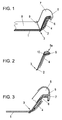
- FIG. 1 shows a cross section through a side region of a vehicle seat according to the invention
- FIG. 2 shows a plate with bubbles for use in a vehicle seat in a further embodiment according to the invention
- FIG. 3 is a view according to FIG Seat cover attachment
- Fig. 4 is a view similar to Fig. 1 with a different placement as well as type of bladder
- Fig. 5 is another embodiment of a bladder for use in a vehicle seat according to the invention.
- a vehicle seat shown schematically and simplified in Fig. 1 comprises a seat pan 1, on which, for example, in the region of the side edges of the backrest a substantially rigid plate 2 is articulated, so that in the connection area a kind of hinge 3 is defined to which the Plate 2 is pivotable relative to the seat pan 1.
- a kind of hinge 3 is defined to which the Plate 2 is pivotable relative to the seat pan 1.
- the plates 2 could also be made in one piece with the seat pan 1. Since the bladder 4 is pressed away from the hinge region 3 by the wedging action between the plate 2 and the seat pan 1, it is advantageously fastened there by a member subjected to tension, for example a flap-like side part of the bladder 4. Not shown in the drawing figures is an optional elastic element which can act on the plates 2 on the seat pan 1 with one of the spreading action of the fluidbehellbaren bladder 4 counteracting restoring force, so that the venting of the bladder 4 is supported and the return movement is performed faster.
- a member subjected to tension for example a flap-like side part of the bladder 4.
- an optional elastic element which can act on the plates 2 on the seat pan 1 with one of the spreading action of the fluidbehellbaren bladder 4 counteracting restoring force, so that the venting of the bladder 4 is supported and the return movement is performed faster.
- seat foam 8 can in this case also be connected to seat pan 1 in the hinge area 3, for example via a tufting 9, which moreover also serves for fastening cover 7 to seat pan 1.
- cover 7 is advantageously secured to the hinge region 3 opposite edge of the plate 2, as better seen in Fig. 3.
- the plate 2 is advantageously designed bent or kinked at least in the region opposite the hinge region 3.
- an aligned forward and in the direction of the contour of the seat surface is formed, on which preferably the bladder 5 is applied.
- the plate 2 with its outer, the hinge region 3 opposite edge of the edge of the seat pan 1 protrude and form the outer boundary of the seat pan 1, as well clearly in Fig. 3 can be seen.
- FIG. 2 an embodiment of a plate 2 according to the invention with two bubbles 4, 5a is shown on opposite sides of the plate 2. Also, this plate is bent or bent in the hinge region 3 opposite region.
- Bladder 5a designed as a folding bubble, in which two at least partially superposed contiguous sections are provided, which are also pneumatically connected and are parallel-ventilated. This results in a larger stroke than in a simple bubble the same footprint.
- This folding bladder 5a can also be connected to the lower bladder 4 via at least one line 6.
- at least one lobe or thread-like extension 10 can be provided, which can be used for fastening the bubble 5 a to the plate 2.
- Fig. 4 shows an arrangement in which the bladder 5 b between the seat cover 7 and seat foam 8, that is spaced from the surface of the plate 2, is arranged.
- This positioning can of course be provided for any type of bladder 5, 5a, 5b, 5c.
- Also embedding any bubbles 5, 5a, 5b, 5c in pockets, slits, cavities, etc. the seat foam 8 is possible.
- This solution with bubbles embedded in the seat foam 8 or between the seat foam 8 and the seat cover 7 can also be used if no pivotable plates 2 are introduced in the seat structure.
- the side adjustment can be increased.
- the bladder 5b provided on the outside of the plate 2 shown in Fig. 4 is in the form of a scarf blister, i.
- the scarf bladder 5b extends from the outer, the hinge region 3 opposite edge on the outside of the plate 2 in the direction of the hinge portion 3, beyond any bending or kink out, towards the inside.
- This bladder 5b may be pneumatically connected to the provided for pivoting the plate 2 bubbles 4.
- FIG. 5 shows an alternative embodiment of a bladder 5c with grooves of different lengths as stroke limiting means, which, in order to achieve a larger lifting height in the edge area, has a section 5d there, which is designed as a folding bladder.
- this portion 5d in the hinge region 3 opposite edge region of the plate 2 may be provided.
- this bubble can be introduced between seat foam 8 and cover 7.
Abstract
Description
Die Erfindung betrifft ein System zur automatischen Verstellung der Kontur, speziell zur Anpassung des Seitenhaltes eines Sitzes, insbesonders Fahrzeugsitz für Automobile, Flugzeuge od. dgl., wobei eine im wesentlichen starre Platte um eine Achse schwenkbar und damit an der gegenüberliegenden Seite aufklappbar mit dem Sitzrahmen oder der Sitzwanne verbunden ist, wobei zwischen der Platte und dem Sitzrahmen oder der Sitzwanne zumindest eine fluidbefüllbare und damit volumsveränderbare Blase befestigt ist, sowie einen Sitz, insbesonders Fahrzeugsitz für Automobile, Flugzeuge od. dgl., mit einer Sitzfläche und allenfalls einer Rückenlehne und/oder Armstützen und/oder Kopfstütze, bei welchem zumindest eine dem Benutzer zugewandte Oberfläche, vorzugsweise die Rückenlehne, an zumindest ihren seitlichen Konturen automatisch veränderbar ist, wobei im Bereich der veränderbaren Konturen und unter dem Bezug des Sitzes und allenfalls unter dem Sitzschaum eine im wesentlichen starre Platte um eine Achse schwenkbar und damit an der gegenüberliegenden Seite aufklappbar mit dem Sitzrahmen oder der Sitzwanne verbunden ist, wobei zwischen der Platte und dem Sitzrahmen oder der Sitzwanne zumindest eine fluidbefüllbare und damit volumsveränderbare Blase befestigt ist.The invention relates to a system for automatic adjustment of the contour, especially for adjusting the lateral support of a seat, in particular vehicle seat for automobiles, aircraft od. Like., Wherein a substantially rigid plate pivotable about an axis and thus hinged on the opposite side with the seat frame or the seat pan is connected, wherein between the plate and the seat frame or the seat pan at least one fluidbefüllbare and thus volume changeable bubble is attached, and a seat, especially vehicle seat for automobiles, aircraft od. Like., With a seat and possibly a backrest and / or or armrests and / or headrest, wherein at least one surface facing the user, preferably the backrest, is automatically changeable on at least its lateral contours, wherein in the region of the variable contours and under the cover of the seat and possibly under the seat foam a substantially rigid pl atte pivotable about an axis and thus hinged on the opposite side is connected to the seat frame or the seat pan, wherein between the plate and the seat frame or the seat pan at least one fluidbefüllbare and thus volume changeable bubble is attached.
Das Bestreben immer komfortablere und auch der Sicherheit dienende Sitze, speziell für Fahrzeuge, zu entwickeln, hat zu Konstruktionen geführt, deren Sitzkonturen an die Bedürfnisse und körperliche Gegebenheiten des Benutzers, aber auch an spezielle Fahrsituationen, angepasst werden können. Dies kann eine einmalige Einstellung des Sitzes umfassen, doch sind auch sich den jeweiligen aktuellen Gegebenheiten dynamisch anpassende Systeme möglich. Für eher längerfristige Grundeinstellungen sind meist mechanische System mit elektrischer Verstellung von beispielsweise der Lehnenneigung, der Sitzlänge, usw. in Verwendung. Auch Systeme mit unter der Oberfläche des Sitzes angeordneten, fluidbefüllbaren Blasen sind bekannt, welche Systeme sich sowohl für langfristige, aber auch rasch veränderliche Einstellungen eignen. Als Arbeitsfluid kommt größtenteils Luft zum Einsatz. So sind derzeit bei vielen Herstellern Fahrzeugsitze mit pneumatischer Konturverstellung zu finden, die unter anderem auch an der Seite der Rückenlehne befindliche Blasen beinhalten, welche der Einstellung und Anpassung des Seitenhaltes des Sitzes erlauben.The desire to develop ever more comfortable and also safety-serving seats, especially for vehicles, has led to constructions whose seat contours can be adapted to the needs and physical conditions of the user, but also to special driving situations. This can include a one-time adjustment of the seat, but also the current circumstances dynamically adaptive systems are possible. For longer-term basic settings are usually mechanical system with electrical adjustment of, for example, the backrest angle, the seat length, etc. in use. Also, systems having fluid-inflatable bladders disposed beneath the surface of the seat are known, which systems are suitable for both long-term and rapidly varying settings. Most of the working fluid used is air. For example, at present many manufacturers find vehicle seats with pneumatic contour adjustment, which include, among other things, bladders located on the side of the backrest, which allow the adjustment and adjustment of the lateral support of the seat.
Die genaue Geometrie sowohl was die dem Benutzer zugewandte Oberfläche des Sitzes als auch den seitlichen Rand des Sitzes betrifft, ist aber bei Systemen mit fluidbefüllbaren Blasen durch deren im wesentlichen abgerundete Form vorgegeben. Bei sich über größere Länge erstreckenden Blasen sind zylindrische Formen vorgegeben. Ebene Flächen oder unregelmäßige Seitenkonturen sind kaum oder nur mit großem Aufwand zu realisieren. Um nun auch eine genau definierte dauerhafte Vorgabe der Oberflächengestaltung bezüglich Randverlauf als auch bezüglich des Höhenverlaufes zu ermöglichen, die dennoch aber in ihrem Ausmaß rasch veränderbar ist, wurde weiters vorgeschlagen, oberhalb zumindest einer an der Sitzstruktur verankerten fluidbefüllbaren und damit volumsveränderbaren Blase noch eine im wesentlichen starre Platten anzubringen.The exact geometry of both the user-facing surface of the seat and the lateral edge of the seat, however, is dictated by its substantially rounded shape in systems having fluid-fillable bladders. For larger-length bubbles, cylindrical shapes are given. Flat surfaces or irregular side contours are difficult or impossible to realize. Now also a well-defined permanent specification of the surface design with respect to edge course as well as to allow for the height profile, which is nevertheless rapidly changeable in its extent, it was further proposed, above at least one anchored to the seat structure fluidbefüllbaren and thus variable volume bubble still attach a substantially rigid plates.
Bei dieser, beispielsweise in der US 4 965 899 A geoffenbarten Bauweise, gestattet die auf der konturverändernden Blase unmittelbar angebrachte Platte durch ihre Formgebung eine dauerhafte Gestaltung der Sitzkontur, unabhängig von der dazwischengeschalteten Blase. Die Einstellbarkeit und auch schnelle Anpassbarkeit des Ausmaßes der Konturverstellung wird durch das pneumatische System gewährleistet. Jedoch ist durch die auf den Blasen schwimmende Lagerung der starren Platte eine Beweglichkeit gegeben, die dem Sinn der Konturgestaltung des Sitzes, beispielsweise einer Seitenkonturanpassung für einen guten Seitenhalt im Sitz, entgegensteht. Dies gilt insbesonders in Zuständen mit nicht vollständig luftbefüllten Blasen, wo diese mechanisch nicht sehr stabil sind und Verschwenkungen bzw. Parallelverschiebungen der Platten gegenüber dem Sitzrahmen leicht möglich sind. Der beschriebene Nachteil vervielfacht sich noch, wenn in Bezug auf den Verstellhub sehr große Konturveränderungen und damit sehr hohe Blasen erforderlich sind.In this construction, disclosed, for example, in US Pat. No. 4,965,899 A, the plate directly attached to the contour-changing bladder, by virtue of its shape, permits a permanent shaping of the seat contour, irrespective of the bladder connected therebetween. The adjustability and also rapid adaptability of the extent of the contour adjustment is ensured by the pneumatic system. However, due to the floating of the bubbles of the rigid plate storage is given a mobility that precludes the sense of contouring of the seat, such as a Seitenkonturanpassung for a good lateral support in the seat. This is especially true in conditions with not completely air-filled bubbles, where these are not mechanically very stable and pivoting or parallel displacements of the plates relative to the seat frame are easily possible. The disadvantage described is multiplied even if in relation to the Verstellhub very large contour changes and thus very high bubbles are required.
Eine im wesentlichen starre Platte, die um eine Achse schwenkbar, damit an der gegenüberliegenden Seite aufklappbar und mit dem Sitzrahmen oder der Sitzwanne verbunden ist, zeigt die GB 2 255 905 A. Zwischen der Platte und dem Sitzrahmen ist zumindest eine fluidbefüllbare und damit volumsveränderbare Blase befestigt, so daß die Platte gegenüber dem Sitzrahmen zur Veränderung der Sitzfläche und/oder Sitzkontur bewegbar ist. Für innerhalb des Sitzes vorgesehene Platten ist der Verstellweg sehr begrenzt, so daß rasche und dennoch großen Konturanpassungen nicht möglich sind.A substantially rigid plate, which is pivotable about an axis, so that hinged on the opposite side and is connected to the seat frame or the seat pan, the
Die Aufgabe der vorliegenden Erfindung war daher ein System der eingangs angegebenen Art, welches bei einfachem Aufbau eine in jedem Zustand möglichst definierte Kontur bzw. Art der Konturveränderung gestattet, welche Veränderung sehr rasch und über sehr große Verstellwege durchführbar ist.The object of the present invention was therefore a system of the type specified, which allows a simple structure in each state as defined contour or type of contour change, which change is very quickly and over very large adjustment feasible.
Zur Lösung dieser Aufgabe ist das System erfindungsgemäß dadurch gekennzeichnet, daß am der Achse gegenüberliegenden Rand der Platte zumindest eine weitere Blase auf der den anderen Blasen gegenüberliegenden Seite vorgesehen ist. Durch die zwischen den Platten vorgesehene Blasenanordnung können die Platten bei weitestgehender Beibehaltung der durch die Form der oberen Platte definierter Kontur verschwenkt werden, so daß in jedem Belüftungszustand durch die Festigkeit der Platte der optimale Stützeffekt erhalten bleibt, wozu auch die Kopplung der Platte mit dem Sitzrahmen bzw. der Sitzwanne beiträgt, die ungewollte Relativbewegungen der Platte gegenüber dem Sitzrahmen bzw. der Sitzwanne verhindert. Durch die weitere Blase wird dann der Bereich der Verstellbarkeit der Sitzkontur noch erweitert, wobei auch die Stabilität bestmöglich erhalten bleibt, da die weitere Blase ja an einer im wesentlichen starren Struktur, nämlich der verschwenkten Platte, angebracht ist, und nicht an darunterliegenden, an sich mechanisch labilen anderen Blasen.To solve this problem, the system according to the invention is characterized in that on the opposite axis of the plate at least one further bubble is provided on the opposite side of the other bubbles. Due to the bladder arrangement provided between the plates, the plates can be pivoted while maintaining the contour defined by the shape of the top plate, so that the optimum support effect is maintained in each ventilation state by the strength of the plate, including the coupling of the plate with the seat frame or contributes to the seat pan, the unwanted relative movements of the plate relative to the seat frame or the seat pan prevented. By the further bubble of the range of adjustability of the seat contour is then extended, with the stability is best possible, since the other bubble is indeed attached to a substantially rigid structure, namely the pivoted plate, and not on underlying, in itself mechanically labile other bubbles.
Gemäß einer vorteilhaften Ausführungsform ist die Platte zumindest im Bereich der der Achse gegenüberliegenden Blase gebogen oder geknickt ausgeführt. Damit wird ein sanfter und komfortabler Übergang zum Seitenrand des Sitzes ermöglicht, gleichzeitig mit einer für die Anbringung und Ausdehnungsrichtung der weiteren Blase optimalen Orientierung dieses Bereichs der Platte.According to an advantageous embodiment, the plate is bent or bent at least in the region of the opposite axis of the axis. Thus, a smooth and comfortable transition to the side edge of the seat is made possible, at the same time with an optimal for the attachment and expansion direction of the other bubble orientation of this area of the plate.
Eine wesentliche Vereinfachung in der Ansteuerung der Blasen ist gemäß einer Ausführungsform gegeben, bei welcher zumindest eine Blase auf jeder Seite der Platte mit zumindest einer anderen Blase auf der gegenüberliegenden Seite der Platte pneumatisch verbunden ist.Substantial simplification in the control of the bladders is provided according to an embodiment in which at least one bladder on each side of the plate is pneumatically connected to at least one other bladder on the opposite side of the plate.
Um die optimale Befüllung bzw. Entleerung auch bei sehr geringen Füllzuständen zu garantieren, kann vorgesehen sein, daß in der pneumatischen Verbindung der Blasen Überströmhilfen eingesetzt sind.In order to guarantee optimal filling and emptying even at very low filling conditions, it can be provided that in the pneumatic connection of the bladder overflow aids are used.
Einen großen Verstellbereich bietet ein System, das als weiteres Erfindungsmerkmal aufweist, daß zumindest eine der Blasen als Faltblase ausgeführt ist, vorzugsweise die Blase am der Achse gegenüberliegenden Rand der Platte.A large adjustment provides a system that has as a further feature of the invention that at least one of the bubbles is designed as a folding bubble, preferably the bladder on the axis opposite edge of the plate.
Eine großflächigere Konturverstellung um im wesentlichen gleiche Höhen kann erzielt werden, wenn die am der Achse gegenüberliegenden Rand der Platte vorgesehene Blase mit Hubbegrenzungsmitteln versehen ist.A larger-scale contour adjustment by substantially equal heights can be achieved if the provided on the axis of the edge of the plate bladder is provided with Hubbegrenzungsmitteln.
Gemäß einer weiteren erfindungsgemäßen Ausführungsform kann vorgesehen sein, daß sich die Blase vom der Achse gegenüberliegenden Rand in Richtung der Achse hin, über eine allfällige Biegung oder einen Knick hinaus, erstreckt.According to a further embodiment of the invention, it may be provided that the bubble extends from the edge opposite the axis in the direction of the axis, beyond any bending or kinking.
Eine Kombination von großflächiger gleichmäßiger Verstellbarkeit und großem Verstellweg am Rand des Sitzes kann durch eine Ausführungsform erreicht werden, bei welcher am der Achse gegenüberliegenden Rand der mit Hubbegrenzungsmitteln versehenen Blase ein als Faltblase ausgelegter Abschnitt vorhanden ist.A combination of large-scale uniform adjustability and large displacement at the edge of the seat can be achieved by an embodiment in which on the opposite axis of the edge provided with Hubbegrenzungsmitteln bladder designed as a folded bubble section is present.
Die eingangs gestellte Aufgabe wird auch gelöst durch einen Sitz wie eingangs angegeben, welcher dadurch gekennzeichnet, daß der Bereich der Platte als System gemäß zumindest einem der vorhergehenden Absätze ausgeführt ist.The object stated in the introduction is also achieved by a seat as stated at the outset, which is characterized in that the region of the plate is designed as a system according to at least one of the preceding paragraphs.
Vorteilhafterweise ist dabei das System gemäß einem der vorhergehenden Absätze unterhalb des Sitzschaums eingesetzt und ist der Sitzschaum im Bereich der Achse mit dem Sitzrahmen oder der Sitzwanne verbunden.Advantageously, the system is used according to one of the preceding paragraphs below the seat foam and the seat foam is connected in the region of the axis with the seat frame or the seat pan.
Um die große Verstellbarkeit nicht zu behindern und unschöne Dehnungsstreifen vermeiden zu können, kann vorgesehen sein, daß der Bezug des Sitzes am der Achse gegenüberliegenden Rand der Platte befestigt ist.In order not to hinder the great adjustability and to avoid unsightly stretch marks, it can be provided that the cover of the seat is fixed to the axis of the opposite edge of the plate.
Gemäß einer weiteren Ausführungsform der Erfindung könnte vorgesehen sein, dass zumindest eine am der Achse gegenüberliegenden Rand der Platte vorgesehene weitere Blase auf der den Blasen gegenüberliegenden Seite von der Oberfläche der Platte beabstandet im Sitzschaum eingebettet ist.According to a further embodiment of the invention, it could be provided that at least one further bladder provided on the opposite edge of the plate is embedded in the seat foam at a distance from the surface of the plate on the side opposite the bladders.
Alternativ dazu oder auch zusätzlich wäre es denkbar, daß zumindest eine am der Achse gegenüberliegenden Rand der Platte vorgesehene weitere Blase auf der den Blasen gegenüberliegenden Seite von der Oberfläche der Platte beabstandet zwischen dem Sitzschaum und dem Sitzbezug eingebettet ist.In der nachfolgenden Beschreibung soll die Erfindung anhand einiger in den Zeichnungen dargestellter Ausführungsbeispiele näher erläutert werden.Alternatively, or in addition, it would be conceivable that at least one provided on the axis of the opposite edge of the plate further bubble on the opposite side of the bladder from the surface of the plate spaced between the seat foam and the seat cover is embedded in the following description, the invention will be explained in more detail with reference to some illustrated in the drawings embodiments.
Dabei zeigt die Fig. 1 einen Querschnitt durch einen Seitenbereich eines Fahrzeugsitzes in erfindungsgemäßer Ausführung, Fig. 2 zeigt eine Platte mit Blasen zur Verwendung in einem Fahrzeugsitz in einer weiteren erfindungsgemäßen Ausführung, Fig. 3 ist eine Ansicht gemäß Fig. 1 mit Darstellung einer erfindungsgemäßen Sitzbezugbefestigung, Fig. 4 ist eine Ansicht gemäß Fig. 1 mit einer anderen Plazierung als auch Art von Blase, und Fig. 5 ist eine weitere Ausführungsform einer Blase zur Verwendung in einem erfindungsgemäßen Fahrzeugsitz.1 shows a cross section through a side region of a vehicle seat according to the invention, FIG. 2 shows a plate with bubbles for use in a vehicle seat in a further embodiment according to the invention, FIG. 3 is a view according to FIG Seat cover attachment, Fig. 4 is a view similar to Fig. 1 with a different placement as well as type of bladder, and Fig. 5 is another embodiment of a bladder for use in a vehicle seat according to the invention.
Die in Fig. 1 schematisch und vereinfacht dargestellte Ausführung eines Fahrzeugsitzes weist eine Sitzwanne 1 auf, an der beispielsweise im Bereich der Seitenränder der Lehne eine im wesentlichen starre Platte 2 angelenkt ist, so daß im Verbindungsbereich eine Art Scharnier 3 definiert ist, um welches die Platte 2 gegenüber der Sitzwanne 1 schwenkbar ist. Zur Verschwenkung der Platte 2 gegenüber der Sitzwanne 1 ist zwischen diesen beiden Teilen zumindest eine fluidbefüllbare und damit volumsveränderbare Blase 4 befestigt. In Abhängigkeit vom Ausmaß der Befüllung der Blase 4 wird die Platten 2 gegenüber der Sitzwanne 1 verschwenkt, wodurch die Veränderung der beispielsweise Seitenkontur bewirkt wird. Bei entsprechend hohem Druck und großem Luftdurchsatz im pneumatischen System ist eine sehr schnelle Verstellung möglich, was auch dynamische Anpassungen an sich rasch verändernde Fahrsituationen gestattet.The embodiment of a vehicle seat shown schematically and simplified in Fig. 1 comprises a
Allenfalls könnte die die Platten 2 auch einstückig mit der Sitzwanne 1 ausgeführt sein. Da die Blase 4 durch die Keilwirkung zwischen Platte 2 und Sitzwanne 1 vom Scharnierbereich 3 weg gedrückt wird, ist sie vorteilhafterweise dort durch ein auf Zug beanspruchtes Element, beispielsweise einen lappenartigen Seitenteil der Blase 4, befestigt. Nicht dargestellt ist in den Zeichnungsfiguren ein optionales elastisches Element, das die Platten 2 auf die Sitzwanne 1 hin mit einer der Spreizwirkung der fluidbefüllbaren Blase 4 entgegenwirkenden Rückstellkraft beaufschlagen kann, damit die Entlüftung der Blase 4 unterstützt und die Rückstellbewegung rascher durchgeführt wird.At most, the
Zusätzlich zur die Verschwenkung der Platte 2 gegenüber der Sitzwanne 1 bewirkenden Blase oder Blasenanordnung 4 ist am dem Scharnierbereich 3 gegenüberliegenden Rand der Platte 2 zumindest eine weitere Blase 5 auf der den anderen Blasen 4 gegenüberliegenden Seite vorgesehen. Diese den Bereich der Verstellbarkeit der Sitzkontur noch erweiternde weitere Blase 5 kann über eine oder mehrere Leitungen 6 mit zumindest einer anderen Blase 4 auf der gegenüberliegenden Seite der Platte 2 pneumatisch verbunden sein. In diesem Fall ist vorteilhafterweise in der pneumatischen Verbindung 6 der Blasen 4, 5 zumindest eine Überströmhilfe eingesetzt.In addition to the pivoting of the
Das oben erläuterte System zur Konturverstellung ist im Sitz unter dem Bezug 7 des Sitzes und vorzugsweise auch unter dem Sitzschaum 8 eingesetzt. Wie in Fig. 1 zu erkennen ist, kann dabei Sitzschaum 8 speziell auch im Scharnierbereich 3 mit der Sitzwanne 1 verbunden sein, beispielsweise über eine Abheftung 9, die darüber hinaus auch gleich zur Befestigung des Bezuges 7 an der Sitzwanne 1 dient. Um die Verschwenkbarkeit der Platte 2 ohne Notwendigkeit von elastischen Einsätzen im Sitzbezug 7 zu gewährleisten, ist der Bezug 7 vorteilhafterweise am dem Scharnierbereich 3 gegenüberliegenden Rand der Platte 2 befestigt, wie besser in Fig. 3 zu erkennen ist.The above-described system for contour adjustment is used in the seat under the
Die Platte 2 ist vorteilhafterweise zumindest im dem Scharnierbereich 3 gegenüberliegenden Bereich gebogen oder geknickt ausgeführt. Damit wird eine nach vorne und in Richtung der Kontur des Sitzes ausgerichtete Fläche gebildet, auf welcher vorzugsweise die Blase 5 aufgebracht ist. Dabei kann die Platte 2 mit ihrem äußeren, dem Scharnierbereich 3 gegenüberliegenden Rand den Rand der Sitzwanne 1 überragen und die äußere Begrenzung der Sitzwanne 1 bilden, wie auch deutlich in Fig. 3 zu sehen ist.The
In Fig. 2 ist eine Ausführungsform einer erfindungsgemäßen Platte 2 mit zwei Blasen 4, 5a auf einander gegenüberliegenden Seiten der Platte 2 dargestellt. Auch diese Platte ist im dem Scharnierbereich 3 gegenüberliegenden Bereich gebogen oder geknickt ausgeführt. Um einen großen Verstellweg zu erzielen, ist die nicht zur Verschwenkung der Platte 2 genutzte Blase 5a als Faltblase ausgeführt, bei welcher zwei zumindest teilweise übereinanderliegende zusammenhängende Abschnitte vorgesehen sind, die auch pneumatisch verbunden sind und parallel be- und entlüftet werden. Damit ergibt sich ein größerer Hub als bei einer einfachen Blase gleicher Grundfläche. Auch diese Faltblase 5a kann über zumindest eine Leitung 6 mit der unteren Blase 4 verbunden sein. Im Übergangsbereich der Faltblase 5a kann zumindest eine lappen- oder fadenförmige Verlängerung 10 vorgesehen sein, die zur Befestigung der Blase 5a an der Platte 2 genutzt werden kann.In Fig. 2, an embodiment of a
Fig. 4 stellt eine Anordnung dar, bei der die Blase 5b zwischen Sitzbezug 7 und Sitzschaum 8, also von der Oberfläche der Platte 2 beabstandet, angeordnet ist. Diese Positionierung kann selbstverständlich für jede beliebige Art von Blase 5, 5a, 5b, 5c vorgesehen sein. Auch eine Einbettung jeglicher Blasen 5, 5a, 5b, 5c in Taschen, Schlitzen, Hohlräumen,usw. des Sitzschaumes 8 ist möglich. Diese Lösung mit im Sitzschaum 8 oder zwischen Sitzschaum 8 und Sitzbezug 7 eingebetteten Blasen kann auch dann zum Einsatz kommen, wenn keine schwenkbaren Platten 2 in der Sitzstruktur eingebracht werden sind. In Kombination mit einer Blase 4 und einem Verbindungskanal 6 mit vorzugsweise einer Überströmhilfe zu Blase 5b bzw. 5c kann die Seitenverstellung verstärkt werden.Fig. 4 shows an arrangement in which the
Vom ihrer Konstruktion her liegt die in Fig. 4 dargestellte un d auf der Außenseite der Platte 2 vorgesehene Blase 5b in Form einer Riefenblase vor, d.h. als Blasenkonstruktion mit Hubbegrenzungsmitteln, eine gleichmäßigere Höhe der Konturverstellung über eine größere Fläche ermöglicht. Die Riefenblase 5b erstreckt sich dabei vom äußeren, dem Scharnierbereich 3 gegenüberliegenden Rand auf der Außenseite der Platte 2 in Richtung des Scharnierbereiches 3, über eine allfällige Biegung oder einen Knick hinaus, nach innen hin. Auch diese Blase 5b kann mit der zum Verschwenken der Platte 2 vorgesehenen Blasen 4 pneumatisch verbunden sein.From their construction, the
Die Fig. 5 zeigt eine alternative Ausführungsform einer Blase 5c mit Riefen unterschiedlicher Länge als Hubbegrenzungsmittel, die zur Erzielung einer größeren Hubhöhe im Randbereich dort einen Abschnitt 5d aufweist, der als Faltblase ausgeführt ist. Vorzugweise wird dieser Abschnitt 5d im dem Scharnierbereich 3 gegenüberliegenden Randbereich der Platte 2 vorgesehen sein. Alternativ kann diese Blase zwischen Sitzschaum 8 und Bezug 7 eingebracht sein.FIG. 5 shows an alternative embodiment of a
Claims (13)
Applications Claiming Priority (1)
| Application Number | Priority Date | Filing Date | Title |
|---|---|---|---|
| AT0037505A AT501046B1 (en) | 2005-03-04 | 2005-03-04 | System for automatic adjustment of contour especially for adjustment of side stop of seat has another bubble provided, on the side opposite to first bubble, on axle of opposite edge of plate |
Publications (2)
| Publication Number | Publication Date |
|---|---|
| EP1698511A1 true EP1698511A1 (en) | 2006-09-06 |
| EP1698511B1 EP1698511B1 (en) | 2010-12-22 |
Family
ID=36570510
Family Applications (1)
| Application Number | Title | Priority Date | Filing Date |
|---|---|---|---|
| EP06110030A Active EP1698511B1 (en) | 2005-03-04 | 2006-02-16 | Device for automatically adjusting the contour of a seat, particularly a seat |
Country Status (3)
| Country | Link |
|---|---|
| EP (1) | EP1698511B1 (en) |
| AT (1) | AT501046B1 (en) |
| DE (1) | DE502006008538D1 (en) |
Cited By (7)
| Publication number | Priority date | Publication date | Assignee | Title |
|---|---|---|---|---|
| WO2008074373A1 (en) * | 2006-12-16 | 2008-06-26 | Volkswagen Aktiengesellschaft | Vehicle seat with pneumatic side cheek upholstery |
| DE102007032449A1 (en) | 2007-07-12 | 2009-01-15 | GM Global Technology Operations, Inc., Detroit | Seat arrangement controlling method for motor vehicle, involves moving or shifting side wall, where lateral support of passenger is safer in driving position and/or driving state than in usage position and/or usage state of wall |
| DE102007032448A1 (en) | 2007-07-12 | 2009-01-22 | GM Global Technology Operations, Inc., Detroit | Motor vehicle seat, has side bolster hinged on another side bolster, where side bolsters respectively comprise venting and/or inflatable and/or evacuatable airtight bubbles, and compressible foam material content arranged in bubbles |
| WO2009018977A2 (en) * | 2007-08-08 | 2009-02-12 | L & P Swiss Holding Company | Side cheek adjustment |
| DE102011116634A1 (en) * | 2011-10-20 | 2013-04-25 | Faurecia Autositze Gmbh | Backrest for vehicle seat, has side flanges with cover material whose one end is defined at attachment point that is provided at actuation units, and resilient sheet whose one end is connected with cover material at attachment point |
| US8602478B2 (en) | 2009-03-11 | 2013-12-10 | GM Global Technology Operations LLC | Vehicle seat with a variable-contour supporting surface |
| CN107458281A (en) * | 2017-06-28 | 2017-12-12 | 重庆延锋安道拓汽车部件系统有限公司 | Self-adapted car seat with flexible seat |
Families Citing this family (3)
| Publication number | Priority date | Publication date | Assignee | Title |
|---|---|---|---|---|
| AT502779A1 (en) * | 2005-10-27 | 2007-05-15 | Hoerbiger Automatisierungstech | SYSTEM FOR THE AUTOMATIC ADJUSTMENT OF THE SEAT CONTOUR AND SEAT, ESPECIALLY VEHICLE SEAT FOR AUTOMOBILE, AIRPLANES OR THE LIKE |
| DE102016004206A1 (en) * | 2016-04-06 | 2017-07-06 | Daimler Ag | Device for changing a contour of a vehicle seat and vehicle seat |
| DE102016220034A1 (en) * | 2016-10-14 | 2018-04-19 | Conti Temic Microelectronic Gmbh | Fluid chamber mat, process for its manufacture and vehicle seat |
Citations (4)
| Publication number | Priority date | Publication date | Assignee | Title |
|---|---|---|---|---|
| US4965899A (en) | 1985-07-16 | 1990-10-30 | Okamoto Industries,Inc. | Air cushion for chair and chair utilizing the air cushion |
| GB2255905A (en) | 1989-04-28 | 1992-11-25 | Okamoto Ind Inc | Adjustable vehicle seat |
| US5280997A (en) * | 1991-03-05 | 1994-01-25 | Mercedes-Benz Ag | Motor vehicle seat |
| DE19938697A1 (en) * | 1999-08-14 | 2001-02-15 | Volkswagen Ag | Motor vehicle seat has pad support with swivel drive to alter angle of inclination and flexibility of seat, and reduce seat flexibility during accidents |
-
2005
- 2005-03-04 AT AT0037505A patent/AT501046B1/en not_active IP Right Cessation
-
2006
- 2006-02-16 EP EP06110030A patent/EP1698511B1/en active Active
- 2006-02-16 DE DE502006008538T patent/DE502006008538D1/en active Active
Patent Citations (4)
| Publication number | Priority date | Publication date | Assignee | Title |
|---|---|---|---|---|
| US4965899A (en) | 1985-07-16 | 1990-10-30 | Okamoto Industries,Inc. | Air cushion for chair and chair utilizing the air cushion |
| GB2255905A (en) | 1989-04-28 | 1992-11-25 | Okamoto Ind Inc | Adjustable vehicle seat |
| US5280997A (en) * | 1991-03-05 | 1994-01-25 | Mercedes-Benz Ag | Motor vehicle seat |
| DE19938697A1 (en) * | 1999-08-14 | 2001-02-15 | Volkswagen Ag | Motor vehicle seat has pad support with swivel drive to alter angle of inclination and flexibility of seat, and reduce seat flexibility during accidents |
Cited By (10)
| Publication number | Priority date | Publication date | Assignee | Title |
|---|---|---|---|---|
| WO2008074373A1 (en) * | 2006-12-16 | 2008-06-26 | Volkswagen Aktiengesellschaft | Vehicle seat with pneumatic side cheek upholstery |
| DE102007032449A1 (en) | 2007-07-12 | 2009-01-15 | GM Global Technology Operations, Inc., Detroit | Seat arrangement controlling method for motor vehicle, involves moving or shifting side wall, where lateral support of passenger is safer in driving position and/or driving state than in usage position and/or usage state of wall |
| DE102007032448A1 (en) | 2007-07-12 | 2009-01-22 | GM Global Technology Operations, Inc., Detroit | Motor vehicle seat, has side bolster hinged on another side bolster, where side bolsters respectively comprise venting and/or inflatable and/or evacuatable airtight bubbles, and compressible foam material content arranged in bubbles |
| WO2009018977A2 (en) * | 2007-08-08 | 2009-02-12 | L & P Swiss Holding Company | Side cheek adjustment |
| DE102007037378A1 (en) * | 2007-08-08 | 2009-02-12 | L & P Swiss Holding Company | Side bolsters adjustment |
| WO2009018977A3 (en) * | 2007-08-08 | 2009-04-16 | L&P Swiss Holding Co | Side cheek adjustment |
| US8602478B2 (en) | 2009-03-11 | 2013-12-10 | GM Global Technology Operations LLC | Vehicle seat with a variable-contour supporting surface |
| DE102011116634A1 (en) * | 2011-10-20 | 2013-04-25 | Faurecia Autositze Gmbh | Backrest for vehicle seat, has side flanges with cover material whose one end is defined at attachment point that is provided at actuation units, and resilient sheet whose one end is connected with cover material at attachment point |
| CN107458281A (en) * | 2017-06-28 | 2017-12-12 | 重庆延锋安道拓汽车部件系统有限公司 | Self-adapted car seat with flexible seat |
| CN107458281B (en) * | 2017-06-28 | 2023-10-20 | 安道拓(重庆)汽车部件有限公司 | Self-adaptive automobile seat with flexible seat cushion |
Also Published As
| Publication number | Publication date |
|---|---|
| AT501046B1 (en) | 2006-06-15 |
| DE502006008538D1 (en) | 2011-02-03 |
| EP1698511B1 (en) | 2010-12-22 |
| AT501046A4 (en) | 2006-06-15 |
Similar Documents
| Publication | Publication Date | Title |
|---|---|---|
| EP1698511B1 (en) | Device for automatically adjusting the contour of a seat, particularly a seat | |
| DE102006037521B4 (en) | System for the automatic adjustment of seats, in particular vehicle seats and seats for automobiles, aircraft or the like with such a system | |
| DE19942351B4 (en) | Seat depth adjustment device for a vehicle seat | |
| DE102011121120B3 (en) | Headrest for motor vehicle seats | |
| DE102008047249A1 (en) | Backrest structure for a motor vehicle seat | |
| DE102008051072A1 (en) | Motor vehicle seat with lumbar support for an anti-whiplash system | |
| DE19825225A1 (en) | Buckle-adjustable support, especially lumbar support, for all types of seats and loungers | |
| WO2003022626A1 (en) | Support element for upholstering on a vehicle seat | |
| DE102014214738A1 (en) | MULTI CONTOUR BUBBLE SYSTEM | |
| DE112013007678T5 (en) | SMA valve for controlling the supply of compressed air to an air cell in a vehicle seat | |
| DE10321744A1 (en) | Headrest mechanism | |
| DE102018117994A1 (en) | TORSION STAB MOUNT FOR ONE VEHICLE, AND TORSION STICK FOR ONE VEHICLE | |
| EP1190894A2 (en) | Backrest for automotive vehicle seats with a frame formed as a pressed sheet | |
| DE202012008758U1 (en) | Automotive seat assembly | |
| DE2902246A1 (en) | Adjustable holder for headrest - has single moulding for sliders and cushion support | |
| DE102007003642A1 (en) | Backrest for seat of motor vehicle, has adjusting element co-acting with supporting element for adjusting supporting element such that location of supporting point at supporting element is unchanged during swiveling adjusting element | |
| EP2605934A1 (en) | Vehicle seat having a convex seat back | |
| EP3626521B1 (en) | Cover device for vehicle seats | |
| DE102017222015A1 (en) | Cladding element for covering a side surface of a vehicle interior | |
| DE3718528A1 (en) | Seat, in particular for motor vehicles | |
| DE102019122533A1 (en) | Cover device for vehicle seats | |
| EP1046538A2 (en) | Vehicle seat, especially motor vehicle seat | |
| DE102013216621A1 (en) | VEHICLE SEAT WITH ADJUSTABLE SIDE WALK | |
| DE102010053190A1 (en) | Seat back structure for vehicle seat, has backrest frame, which has front side facing back of user of seat and backrest cushion | |
| AT412962B (en) | FASTENING ARRANGEMENT FOR INFLATABLE BODIES |
Legal Events
| Date | Code | Title | Description |
|---|---|---|---|
| PUAI | Public reference made under article 153(3) epc to a published international application that has entered the european phase |
Free format text: ORIGINAL CODE: 0009012 |
|
| AK | Designated contracting states |
Kind code of ref document: A1 Designated state(s): AT BE BG CH CY CZ DE DK EE ES FI FR GB GR HU IE IS IT LI LT LU LV MC NL PL PT RO SE SI SK TR |
|
| AX | Request for extension of the european patent |
Extension state: AL BA HR MK YU |
|
| 17P | Request for examination filed |
Effective date: 20070305 |
|
| AKX | Designation fees paid |
Designated state(s): DE FR |
|
| 17Q | First examination report despatched |
Effective date: 20070420 |
|
| RAP1 | Party data changed (applicant data changed or rights of an application transferred) |
Owner name: HOERBIGER AUTOMATISIERUNGSTECHNIK HOLDING GMBH |
|
| RAP1 | Party data changed (applicant data changed or rights of an application transferred) |
Owner name: HOERBIGER AUTOMOTIVE KOMFORTSYSTEME GMBH |
|
| GRAP | Despatch of communication of intention to grant a patent |
Free format text: ORIGINAL CODE: EPIDOSNIGR1 |
|
| GRAS | Grant fee paid |
Free format text: ORIGINAL CODE: EPIDOSNIGR3 |
|
| GRAA | (expected) grant |
Free format text: ORIGINAL CODE: 0009210 |
|
| AK | Designated contracting states |
Kind code of ref document: B1 Designated state(s): DE FR |
|
| REF | Corresponds to: |
Ref document number: 502006008538 Country of ref document: DE Date of ref document: 20110203 Kind code of ref document: P |
|
| REG | Reference to a national code |
Ref country code: DE Ref legal event code: R096 Ref document number: 502006008538 Country of ref document: DE Effective date: 20110203 |
|
| PLBE | No opposition filed within time limit |
Free format text: ORIGINAL CODE: 0009261 |
|
| STAA | Information on the status of an ep patent application or granted ep patent |
Free format text: STATUS: NO OPPOSITION FILED WITHIN TIME LIMIT |
|
| 26N | No opposition filed |
Effective date: 20110923 |
|
| REG | Reference to a national code |
Ref country code: DE Ref legal event code: R097 Ref document number: 502006008538 Country of ref document: DE Effective date: 20110923 |
|
| REG | Reference to a national code |
Ref country code: FR Ref legal event code: PLFP Year of fee payment: 11 |
|
| REG | Reference to a national code |
Ref country code: FR Ref legal event code: PLFP Year of fee payment: 12 |
|
| REG | Reference to a national code |
Ref country code: DE Ref legal event code: R079 Ref document number: 502006008538 Country of ref document: DE Free format text: PREVIOUS MAIN CLASS: B60N0002440000 Ipc: B60N0002900000 |
|
| REG | Reference to a national code |
Ref country code: FR Ref legal event code: PLFP Year of fee payment: 13 |
|
| PGFP | Annual fee paid to national office [announced via postgrant information from national office to epo] |
Ref country code: FR Payment date: 20230119 Year of fee payment: 18 |
|
| PGFP | Annual fee paid to national office [announced via postgrant information from national office to epo] |
Ref country code: DE Payment date: 20230119 Year of fee payment: 18 |