EP1701187A2 - Hermaphroditic insert member for connectors - Google Patents
Hermaphroditic insert member for connectors Download PDFInfo
- Publication number
- EP1701187A2 EP1701187A2 EP06012848A EP06012848A EP1701187A2 EP 1701187 A2 EP1701187 A2 EP 1701187A2 EP 06012848 A EP06012848 A EP 06012848A EP 06012848 A EP06012848 A EP 06012848A EP 1701187 A2 EP1701187 A2 EP 1701187A2
- Authority
- EP
- European Patent Office
- Prior art keywords
- insert member
- connector
- insert
- recess
- end portion
- Prior art date
- Legal status (The legal status is an assumption and is not a legal conclusion. Google has not performed a legal analysis and makes no representation as to the accuracy of the status listed.)
- Withdrawn
Links
Images


Classifications
-
- G—PHYSICS
- G02—OPTICS
- G02B—OPTICAL ELEMENTS, SYSTEMS OR APPARATUS
- G02B6/00—Light guides; Structural details of arrangements comprising light guides and other optical elements, e.g. couplings
- G02B6/24—Coupling light guides
- G02B6/36—Mechanical coupling means
- G02B6/38—Mechanical coupling means having fibre to fibre mating means
- G02B6/3807—Dismountable connectors, i.e. comprising plugs
- G02B6/3873—Connectors using guide surfaces for aligning ferrule ends, e.g. tubes, sleeves, V-grooves, rods, pins, balls
- G02B6/3874—Connectors using guide surfaces for aligning ferrule ends, e.g. tubes, sleeves, V-grooves, rods, pins, balls using tubes, sleeves to align ferrules
-
- G—PHYSICS
- G02—OPTICS
- G02B—OPTICAL ELEMENTS, SYSTEMS OR APPARATUS
- G02B6/00—Light guides; Structural details of arrangements comprising light guides and other optical elements, e.g. couplings
- G02B6/24—Coupling light guides
- G02B6/36—Mechanical coupling means
- G02B6/38—Mechanical coupling means having fibre to fibre mating means
- G02B6/3807—Dismountable connectors, i.e. comprising plugs
- G02B6/381—Dismountable connectors, i.e. comprising plugs of the ferrule type, e.g. fibre ends embedded in ferrules, connecting a pair of fibres
- G02B6/3826—Dismountable connectors, i.e. comprising plugs of the ferrule type, e.g. fibre ends embedded in ferrules, connecting a pair of fibres characterised by form or shape
- G02B6/383—Hermaphroditic connectors, i.e. two identical plugs mating with one another, each plug having both male and female diametrically opposed engaging parts
-
- G—PHYSICS
- G02—OPTICS
- G02B—OPTICAL ELEMENTS, SYSTEMS OR APPARATUS
- G02B6/00—Light guides; Structural details of arrangements comprising light guides and other optical elements, e.g. couplings
- G02B6/24—Coupling light guides
- G02B6/36—Mechanical coupling means
- G02B6/38—Mechanical coupling means having fibre to fibre mating means
- G02B6/3807—Dismountable connectors, i.e. comprising plugs
- G02B6/3869—Mounting ferrules to connector body, i.e. plugs
-
- G—PHYSICS
- G02—OPTICS
- G02B—OPTICAL ELEMENTS, SYSTEMS OR APPARATUS
- G02B6/00—Light guides; Structural details of arrangements comprising light guides and other optical elements, e.g. couplings
- G02B6/24—Coupling light guides
- G02B6/36—Mechanical coupling means
- G02B6/38—Mechanical coupling means having fibre to fibre mating means
- G02B6/3807—Dismountable connectors, i.e. comprising plugs
- G02B6/389—Dismountable connectors, i.e. comprising plugs characterised by the method of fastening connecting plugs and sockets, e.g. screw- or nut-lock, snap-in, bayonet type
- G02B6/3891—Bayonet type
-
- G—PHYSICS
- G02—OPTICS
- G02B—OPTICAL ELEMENTS, SYSTEMS OR APPARATUS
- G02B6/00—Light guides; Structural details of arrangements comprising light guides and other optical elements, e.g. couplings
- G02B6/24—Coupling light guides
- G02B6/36—Mechanical coupling means
- G02B6/38—Mechanical coupling means having fibre to fibre mating means
- G02B6/3807—Dismountable connectors, i.e. comprising plugs
- G02B6/3873—Connectors using guide surfaces for aligning ferrule ends, e.g. tubes, sleeves, V-grooves, rods, pins, balls
- G02B6/3874—Connectors using guide surfaces for aligning ferrule ends, e.g. tubes, sleeves, V-grooves, rods, pins, balls using tubes, sleeves to align ferrules
- G02B6/3878—Connectors using guide surfaces for aligning ferrule ends, e.g. tubes, sleeves, V-grooves, rods, pins, balls using tubes, sleeves to align ferrules comprising a plurality of ferrules, branching and break-out means
-
- G—PHYSICS
- G02—OPTICS
- G02B—OPTICAL ELEMENTS, SYSTEMS OR APPARATUS
- G02B6/00—Light guides; Structural details of arrangements comprising light guides and other optical elements, e.g. couplings
- G02B6/24—Coupling light guides
- G02B6/36—Mechanical coupling means
- G02B6/38—Mechanical coupling means having fibre to fibre mating means
- G02B6/3807—Dismountable connectors, i.e. comprising plugs
- G02B6/3887—Anchoring optical cables to connector housings, e.g. strain relief features
- G02B6/3888—Protection from over-extension or over-compression
-
- H—ELECTRICITY
- H01—ELECTRIC ELEMENTS
- H01R—ELECTRICALLY-CONDUCTIVE CONNECTIONS; STRUCTURAL ASSOCIATIONS OF A PLURALITY OF MUTUALLY-INSULATED ELECTRICAL CONNECTING ELEMENTS; COUPLING DEVICES; CURRENT COLLECTORS
- H01R13/00—Details of coupling devices of the kinds covered by groups H01R12/70 or H01R24/00 - H01R33/00
- H01R13/02—Contact members
- H01R13/28—Contacts for sliding cooperation with identically-shaped contact, e.g. for hermaphroditic coupling devices
Definitions
- the invention relates to connector insert members and in particular to hermaphroditic connector insert members of the type used for connecting optical fibre cables.
- Optical fibre communication systems often have to operate in harsh conditions and environments.
- the cables and the connectors that join the cable lengths together need to be of a rugged construction. It is seen as an advantage if the connectors are hermaphroditic, so that all plug and bulkhead connectors can mate together without need for adapters. This is advantage is not limited to optical systems as it will be appreciated that hermaphroditic connectors have applications in many systems including electrical and/or hybrid electrical and optical systems.
- This known pin and socket arrangement serves to align, within optical systems, the optical channels both axially and angularly.
- the insert member is machined to extremely fine tolerance and it achieves the required level of perpendicularity between the front mating surface and the channel bores because it is machined in one single operation.
- each channel typically has a coated glass window in a screw housing.
- the pin and socket are not easy to keep clean, and the pin is also prone to damage and as a result tends to seize up in its socket which prevents the connector from de-mating.
- the above pin and socket arrangement is typically used within optical applications for expanded beam connectors.
- a polished optical fibre end is supported in a ferrule and is aligned axially with a lens to produce an expanded beam that passes between the two halves of the connector and is focused down through another lens onto the receiving fibre end surface.
- An alternative method of transmitting light between two connector half portions is to use a butt joint connection.
- Butt joint connections comprise two opposing optical fibres each being supported in a ferrule, and when the fibre emerges from the ferrule end it is polished to provide a surface which is suitable to transfer light onto the opposing equivalent fibre end in the other half portion.
- the two ferrules are axially aligned and positioned such that the two fibre ends are in contact.
- known methods typically employ a sleeve to align the two mating ferrules. This results in very low loss coupling, providing that there is no contamination.
- it is difficult to clean inside an alignment sleeve which is why this type of connection has normally only been used in clean environments.
- the insert member according to one aspect of the present invention has no pin and socket.
- the alignment is provided by lugs on the edge of the insert. These lugs or upstanding edges provide a more accurate angular alignment mechanism than previously obtainable.
- the insert member of the present invention may be adapted for both expanded beam and butt joint connections. Also, there are fewer nooks or crannies to harbour dirt.
- an optical insert member of the present invention provides for high precision alignment of the optical components without the use of a protruding alignment pin.
- the insert member of the present invention is also suited for butt joint harsh environment connector systems, both in optical and electrical adaptations. With the insert member of the present invention the optical fibres are brought into contact without a requirement for an alignment sleeve making it easier to clean.
- an insert member for a connector comprising a body structure with an hermaphroditic profiled end.
- the body structure is substantially cylindrical.
- the profiled end is adapted to mate with a similarly profiled end on a second insert member.
- the profiled end comprises one or more, typically two, upstanding edges and one or more, typically two, recesses.
- the upstanding edges and recesses are profiled such that one such edge is mateable with and mates with one such recess.
- the insert member comprises one or more through bores for receiving one or more optical fibre ferrules and/or lenses.
- the lenses are spherical.
- the insert member may be further adapted to incorporate a single window element extending across an open end of the bores.
- the insert member further comprises a seal for retaining the window element to said body structure.
- the window element extends across substantially the whole end of the body structure other than at the peripheral edge thereof.
- the insert member may be provided with a recess to accommodate said window element.
- the insert member may be further adapted to incorporate a plurality of lobes extending radially outwardly from the body of the insert member.
- the lobes are provided at the distal end of the body from the profiled end of the body structure.
- the lobes are adapted to provide an easy alignment mechanism for aligning an insert member within an insert housing, and are therefore adapted to facilitate only one position of insertion.
- three such lobes are provided and are not equally spaced circumferentially about the end of the body structure.
- the lobes are preferably adapted to be received in corresponding channels in a housing in which the insert member is to be housed during use.
- the invention also describes insert member for connectors substantially as hereinafter described with reference to the following drawings.
- Figure 1 shows an insert member 20 according to the present invention. It comprises a substantially cylindrical body 240 having a peripheral flange 260 at one end thereof. The other end of the body 240 remote from the flange 260 has a hermaphroditic mating profile such that two such insert members 220 may be abutted end to end. The profile is such that when two such insert members 220 are mated, their mutual engagement prevents relative rotation between such insert members.
- the engaging profile comprises two upstanding peripheral edges 280 at diametrically opposed sides of the body 240, and two peripheral recesses 300 at diametrically opposed sides of the body 240, the recesses extending at right angles to the upstanding edges.
- the recesses 300 are profiled to correspond to the profiles of the upstanding edges 280 such that, in use, when two insert members are mated, the edges 280 of one insert member locate in the recesses 300 of the other member and vice versa.
- the edges 280 have an outer side or surface 282 having a curvature corresponding to that of the cylindrical body 240 and an inner side or inner engagement surface 284 which is substantially straight or planar.
- the recesses 300 have an outer side wall 302 at least a portion of which is adapted to engage with the inner engagement surface 284 of the upstanding edge 280.
- the exterior portion of the base of the recesses has a perimeter of curvature 304 corresponding to that of the cylindrical body 240.
- One or more longitudinal through bores 320 are provided through the insert member 220 for receiving one or more optical fibres ferrules, electrical cable connectors or the like.
- the central region of the body 240 which accommodates the bores 320 is recessed from the mating profiled end of the insert member to form a recess 340, typically circular, having a surrounding peripheral raised edge 360 which in use acts to protect the optical elements located in the bores.
- Such a circular recess 340 may also accommodate a single large circular window for protecting the optical elements, while allowing visual access to each bore. It will be appreciated by those skilled in the art that the inner dimensions of each bore may have to be adapted so as to enable the fitting of a fibre optic ferrule or electrical connector therein.
- Figure 2 details the hermaphroditic profiled end 820 of the insert member of the present invention.
- the profiled end 820 has an engaging profile comprising two upstanding peripheral edges or lugs 280 at diametrically opposed sides of the body 240, and two peripheral recesses 300 at diametrically opposed sides of the body 240, the recesses extending substantially at a right angle to the upstanding edges, such that on presentation of two compatible insert members 220, each upstanding lug 280 of a first insert member has a corresponding recess 300 with which it is engageable on the second insert member.
- Each upstanding lug 280 comprises a presentation surface 400, which, when in a mated position, is presented to and abuts against a corresponding presentation surface 410 of the recess 300.
- the presentation surface 400 is substantially planar, extending inwardly and transversely to the outer surface or side 282 of the upstanding lug 280. At a distal location from the outer surface 282 the presentation surface 400 tapers inwardly towards an inner side or inner engagement surface 284, forming a taper region 285 therebetween.
- the recess 300 has a side wall 301 located between the base 415 of the recess and the peripheral raised edge 360 of the insert member 220.
- a portion of the side wall 301 defines a recess engagement surface 302, the recess engagement surface 302 being adapted to engage with the inner engagement surface 284 of the upstanding edge or lug 280.
- a presentation surface 410 of the recess forms a portion of the base 415 of the recess, the base 415 extending from the perimeter 304 of the recess inwardly and substantially perpendicularly to the outer circumference of the insert member 220 to a corner 420 remote from the perimeter, where it meets the inner side wall 301.
- an outwardly and upwardly extending lower taper region 303 of the side wall 301 is formed, the lower taper region 303 extending from the base of the recess toward the recess engagement surface 302.
- the profiles of the recess engagement surface 302, the inner engagement surface 284, and the two presentation surfaces 410, 415 are such that when two corresponding insert members are mated, as shown in Figure 2, these surfaces abut one another.
- the area formed, when the two corresponding insert members mate, between the lower taper region 303 of the recess and the taper region 285 of the upstanding edge, defines a dirt collection area where any dirt that is incident on the mating surfaces may collect, thereby ensuring that a good mating between the respective insert members is achievable.
- the side wall 301 tapers inwardly again, forming an upper taper region 424 of the recess.
- the upper taper region is tapered inwardly at an angle of approximately 60° to the perpendicular, and facilitates ease of presentation of the upstanding edge or lug to its respective recess.
- the side wall of the recess is approximately 1.8 mm, the upper taper region being 0.6 mm, and the recess engagement surface 0.45 mm.
- the interference fit provided by the interaction of opposing upstanding edges and the recesses enables a 3-8 micron interference, typically about 5 microns, which effects good quality optical mating for the fibre optic ferrules mounted within each insert member. If one attempts to provide too much interference between the opposing insert members, then a phenomenon of galling may occur, too little may result in a loose inter-engagement.
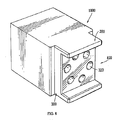
- Figures 3 to 7 show an insert member 800 somewhat modified from the insert member hereinbefore described.
- the insert member comprises a cylindrical body 240 having a hermaphroditic profiled end region 820 with upstanding edges and recesses similar to that described with reference to the previous embodiment.
- the body 240 has a circumferential groove 840 for accommodating a seal in order to assist the securement of the insert member within a connector insert housing, which may be of a conventional type, or the type of the present invention, as hereinbefore described.
- the end 860 of the body remote from the hermaphroditic profiled end region 820 comprises a plurality of lobes 880 which extend radially outward beyond the principal circumference of the body 240. Typically, three such lobes 880 are provided and are not equally spaced about the circumference of the end region 860. In this preferred embodiment, the lobes are defined by longitudinally recessed regions 900.
- the end region 860 comprises three lobes 880, each lobe being defined by a recess on either side thereof and non-lobed regions 920 extending between adjacent recesses 900.
- the non-lobed regions 920 have an external curvature corresponding to that of the cylindrical body 800 and form an extension thereof.
- the lobes 880 project beyond the outer circumference of the body 800.
- the insert member 800 locates in an insert housing 102 such that the lobes 880 align and locate with corresponding channels 885 formed in the internal wall of the insert housing 102.
- the insert housing internal wall has three channels 885 formed therein, the channels being not equally spaced around the internal circumference.
- the channels 885 correspond to the depth and curvature of the lobes 880.
- Figure 7 shows inserted insert members 800 within their respective insert housings 102.
- an insert retainer (not shown) using the internal screw threads 120 of the insert housing 102.
- Each insert member has a plurality of longitudinal bores provided therethrough. As detailed previously, these bores are adapted to accommodate optical ferrules or electrical connectors depending on the application of the connector coupling.
- the bores typically comprise, at the end region 860 of the body remote from the hermaphroditic profiled end, a main aperture 940 serving as an entry port for the introduction of the ferrules into the housing.
- the bore extends from this main aperture 940 through the body of the insert member to an exit port 946 at the end of the body proximal to the hermaphroditic profiled end 820.
- a second sub-aperture 945 may be provide adjacent the main aperture 940 and intersecting a peripheral edge of the corresponding main aperture to form a keyhole effect bore.
- the keyhole effect may extend partially or fully along the length of the bore.
- an optical fibre ferrule 950 is provided with a peripheral lug 955 which locates in the sub-aperture 945 of the bore, thereby providing accurate and stable alignment of the ferrule within the bore.
- the mating of the lug with the sub-aperture prevents rotational movement of the ferrule within the bore.
- the provision of a single sub-aperture for each bore ensures that the ferrule can be axially aligned only in a single desired direction.
- central region of the insert member such as shown in Figure 5, which accommodates the bores 940 may be recessed from the end 860 if so required; for example to accommodate additional components of the ferrules.
- One specific application of the present invention involves the connection of 8 optical fibre channels, each optical fibre being locatable in a respective individual bore 940 of the insert member. It is desirable to mate the respective channels from one insert member with those of the other member to within a 1 micron accuracy. For example, in the situation of using a butt join connection between opposing single mode fibres, it is common to have to align an 8 micron fibre with an equivalent 8 micron fibre in the opposing insert members. It is evident that any deviation from true mating will result in poor transmission through the connector and high losses.
- Figures 9 and 10 are graphs illustrating the % loss against true positional error for connectors of the present invention in both single and multimode application, and an examination of the Figures shows the importance of correct alignment.
- Figure 8 shows a modification to the insert member previously described.
- the member 1000 is substantially rectangular, but again incorporates co-operable upstanding lugs 280 and recesses 300 at the hermaphroditic mating presentation region 820 of the insert member 1000.
- This embodiment is specifically suited to electronic connector applications and may be tooled from plastic material.
- the insert member and insert housing of the present invention have been described and illustrated with reference to specific individual components that for specific applications it may be advantageous to integrally form an insert housing with an insert member.
Abstract
Description
- The invention relates to connector insert members and in particular to hermaphroditic connector insert members of the type used for connecting optical fibre cables.
- Optical fibre communication systems often have to operate in harsh conditions and environments. The cables and the connectors that join the cable lengths together need to be of a rugged construction. It is seen as an advantage if the connectors are hermaphroditic, so that all plug and bulkhead connectors can mate together without need for adapters. This is advantage is not limited to optical systems as it will be appreciated that hermaphroditic connectors have applications in many systems including electrical and/or hybrid electrical and optical systems.
- Although there are problems in connector systems with providing a rugged connection suitable for harsh conditions that can be closed or opened easily when required, additional problems arise when aligning the components within the connectors so as to achieve optimum alignment/interengagement between related components when the two connector half portions are connected so as to form a sealed connector. Typically, the components are housed within an insert member, opposing insert members coming into inter-engagement once the connector half portions are connected so as to form the sealed connector. In known systems this alignment of the opposing members is achieved using a pin and socket arrangement, wherein one of the insert members comprises a pin which is adapted to be received within a socket of the opposing insert member.
- This known pin and socket arrangement serves to align, within optical systems, the optical channels both axially and angularly. The insert member is machined to extremely fine tolerance and it achieves the required level of perpendicularity between the front mating surface and the channel bores because it is machined in one single operation. In order to protect the optical elements from contamination each channel typically has a coated glass window in a screw housing. The pin and socket are not easy to keep clean, and the pin is also prone to damage and as a result tends to seize up in its socket which prevents the connector from de-mating.
- The above pin and socket arrangement is typically used within optical applications for expanded beam connectors. In such expanded beam connectors or lens connectors a polished optical fibre end is supported in a ferrule and is aligned axially with a lens to produce an expanded beam that passes between the two halves of the connector and is focused down through another lens onto the receiving fibre end surface. An alternative method of transmitting light between two connector half portions is to use a butt joint connection. Butt joint connections comprise two opposing optical fibres each being supported in a ferrule, and when the fibre emerges from the ferrule end it is polished to provide a surface which is suitable to transfer light onto the opposing equivalent fibre end in the other half portion. In use, the two ferrules are axially aligned and positioned such that the two fibre ends are in contact. When aligning opposing insert members which house the ferrules supporting the fibres, known methods typically employ a sleeve to align the two mating ferrules. This results in very low loss coupling, providing that there is no contamination. However, it is difficult to clean inside an alignment sleeve, which is why this type of connection has normally only been used in clean environments.
- The expanded beam method traditionally has been used in harsh environment applications since the expanded beam gives a better chance of transmitting light in the presence of contamination, whereas in alternative butt joint connections even small particles of dust may reduce the transferred optical power to unacceptably low levels. Problems with expanded beam include the fact that, as they are extremely sensitive to angular misalignment, excess loss is often caused by an accumulation of axial errors among the optical elements involved, which leads to angular misalignment.
- There is therefore a requirement to provide an improved alignment means for aligning two opposing insert members when connecting them together into a sealed connector.
- It is an object of the present invention to provide an improved alignment means for aligning specific components within a connector during the coupling process.
- The insert member according to one aspect of the present invention has no pin and socket. The alignment is provided by lugs on the edge of the insert. These lugs or upstanding edges provide a more accurate angular alignment mechanism than previously obtainable. When the insert member is used to house optical elements, the lug arrangement allows optical elements to be protected by a large coated window so that any contamination is easy to clean away. Furthermore, the insert member of the present invention may be adapted for both expanded beam and butt joint connections. Also, there are fewer nooks or crannies to harbour dirt. Thus, if the connector is used for an expanded beam connector, an optical insert member of the present invention provides for high precision alignment of the optical components without the use of a protruding alignment pin. This allows the insert member to have a protective window that covers all of the optical elements thereby making it neat and clean. A seal that retains both the protective window and prevents the ingress of any incident water which may otherwise contaminate the optical components may be provided on the insert member. The insert member of the present invention is also suited for butt joint harsh environment connector systems, both in optical and electrical adaptations. With the insert member of the present invention the optical fibres are brought into contact without a requirement for an alignment sleeve making it easier to clean.
- According to one aspect of the present invention there is provided an insert member for a connector, the insert member comprising a body structure with an hermaphroditic profiled end. Preferably, the body structure is substantially cylindrical. The profiled end is adapted to mate with a similarly profiled end on a second insert member. Preferably, the profiled end comprises one or more, typically two, upstanding edges and one or more, typically two, recesses. Preferably, the upstanding edges and recesses are profiled such that one such edge is mateable with and mates with one such recess.
- Preferably two such edges are provided at opposing sides of said end and preferably two such recesses are provided at opposing sides of said end, said recesses being substantially perpendicular and at right angles to said edges. Preferably, the insert member comprises one or more through bores for receiving one or more optical fibre ferrules and/or lenses. Typically if employed the lenses are spherical.
- The insert member may be further adapted to incorporate a single window element extending across an open end of the bores. Preferably, if incorporated, the insert member further comprises a seal for retaining the window element to said body structure. Preferably the window element extends across substantially the whole end of the body structure other than at the peripheral edge thereof. The insert member may be provided with a recess to accommodate said window element.
- The insert member may be further adapted to incorporate a plurality of lobes extending radially outwardly from the body of the insert member. Typically the lobes are provided at the distal end of the body from the profiled end of the body structure. The lobes are adapted to provide an easy alignment mechanism for aligning an insert member within an insert housing, and are therefore adapted to facilitate only one position of insertion. Preferably, three such lobes are provided and are not equally spaced circumferentially about the end of the body structure.
- The lobes are preferably adapted to be received in corresponding channels in a housing in which the insert member is to be housed during use.
- The invention also describes insert member for connectors substantially as hereinafter described with reference to the following drawings.
-
- Figure 1 is perspective view of a first embodiment of an insert member according to the present invention,
- Figure 2 is a detail, both in perspective and section of a hermaphroditic mating region of the insert member of the present invention,
- Figure 3 is perspective view of a modification to the insert member of Figure 9, and showing the presentation of fibre optic ferrules into the insert member,
- Figure 4 is a perspective view of two mated insert members of the present invention,
- Figure 5 is perspective view of a modification to the insert member of the present Invention,
- Figure 6 is a view showing insert members of the present invention being presented to insert housings,
- Figure 7 is a view of the insert members of the present invention within the insert housings,
- Figure 8 is a perspective view of an alternative embodiment of the insert member of the present invention,
- Figure 1 shows an
insert member 20 according to the present invention. It comprises a substantiallycylindrical body 240 having aperipheral flange 260 at one end thereof. The other end of thebody 240 remote from theflange 260 has a hermaphroditic mating profile such that twosuch insert members 220 may be abutted end to end. The profile is such that when twosuch insert members 220 are mated, their mutual engagement prevents relative rotation between such insert members. The engaging profile comprises two upstandingperipheral edges 280 at diametrically opposed sides of thebody 240, and twoperipheral recesses 300 at diametrically opposed sides of thebody 240, the recesses extending at right angles to the upstanding edges. - The
recesses 300 are profiled to correspond to the profiles of theupstanding edges 280 such that, in use, when two insert members are mated, theedges 280 of one insert member locate in therecesses 300 of the other member and vice versa. Typically, theedges 280 have an outer side orsurface 282 having a curvature corresponding to that of thecylindrical body 240 and an inner side orinner engagement surface 284 which is substantially straight or planar. Similarly, therecesses 300 have anouter side wall 302 at least a portion of which is adapted to engage with theinner engagement surface 284 of theupstanding edge 280. The exterior portion of the base of the recesses has a perimeter ofcurvature 304 corresponding to that of thecylindrical body 240. - One or more longitudinal through
bores 320 are provided through theinsert member 220 for receiving one or more optical fibres ferrules, electrical cable connectors or the like. Typically, the central region of thebody 240 which accommodates thebores 320 is recessed from the mating profiled end of the insert member to form arecess 340, typically circular, having a surrounding peripheral raisededge 360 which in use acts to protect the optical elements located in the bores. - Such a
circular recess 340 may also accommodate a single large circular window for protecting the optical elements, while allowing visual access to each bore. It will be appreciated by those skilled in the art that the inner dimensions of each bore may have to be adapted so as to enable the fitting of a fibre optic ferrule or electrical connector therein. - Figure 2 details the hermaphroditic profiled
end 820 of the insert member of the present invention. As detailed previously with regard to Figure 9, the profiledend 820 has an engaging profile comprising two upstanding peripheral edges or lugs 280 at diametrically opposed sides of thebody 240, and twoperipheral recesses 300 at diametrically opposed sides of thebody 240, the recesses extending substantially at a right angle to the upstanding edges, such that on presentation of twocompatible insert members 220, eachupstanding lug 280 of a first insert member has acorresponding recess 300 with which it is engageable on the second insert member. - Each
upstanding lug 280 comprises apresentation surface 400, which, when in a mated position, is presented to and abuts against acorresponding presentation surface 410 of therecess 300. Thepresentation surface 400 is substantially planar, extending inwardly and transversely to the outer surface orside 282 of theupstanding lug 280. At a distal location from theouter surface 282 thepresentation surface 400 tapers inwardly towards an inner side orinner engagement surface 284, forming ataper region 285 therebetween. - Similarly, the
recess 300 has aside wall 301 located between the base 415 of the recess and the peripheral raisededge 360 of theinsert member 220. A portion of theside wall 301 defines arecess engagement surface 302, therecess engagement surface 302 being adapted to engage with theinner engagement surface 284 of the upstanding edge orlug 280. Apresentation surface 410 of the recess forms a portion of thebase 415 of the recess, thebase 415 extending from theperimeter 304 of the recess inwardly and substantially perpendicularly to the outer circumference of theinsert member 220 to acorner 420 remote from the perimeter, where it meets theinner side wall 301. - At the
corner 420, an outwardly and upwardly extendinglower taper region 303 of theside wall 301 is formed, thelower taper region 303 extending from the base of the recess toward therecess engagement surface 302. The profiles of therecess engagement surface 302, theinner engagement surface 284, and the twopresentation surfaces lower taper region 303 of the recess and thetaper region 285 of the upstanding edge, defines a dirt collection area where any dirt that is incident on the mating surfaces may collect, thereby ensuring that a good mating between the respective insert members is achievable. - Between the
recess engagement surface 302 and the peripheral raisededge 360 of the insert member, theside wall 301 tapers inwardly again, forming an upper taper region 424 of the recess. The upper taper region is tapered inwardly at an angle of approximately 60° to the perpendicular, and facilitates ease of presentation of the upstanding edge or lug to its respective recess. - In one exemplary embodiment of the present invention, the side wall of the recess is approximately 1.8 mm, the upper taper region being 0.6 mm, and the recess engagement surface 0.45 mm. To ensure a good mating between opposing insert members, it is preferential to define the dimensions of the recess side wall to be slightly less that that of the upstanding edge. This ensures that when mated, the presentation surfaces of the two opposing insert members come into contact prior to any contact between the upper
peripheral edges 360 of the respective insert members. The interference fit provided by the interaction of opposing upstanding edges and the recesses enables a 3-8 micron interference, typically about 5 microns, which effects good quality optical mating for the fibre optic ferrules mounted within each insert member. If one attempts to provide too much interference between the opposing insert members, then a phenomenon of galling may occur, too little may result in a loose inter-engagement. - Figures 3 to 7 show an
insert member 800 somewhat modified from the insert member hereinbefore described. The same reference numerals will be used to describe equivalent components. Again, in this embodiment the insert member comprises acylindrical body 240 having a hermaphroditic profiledend region 820 with upstanding edges and recesses similar to that described with reference to the previous embodiment. Thebody 240 has acircumferential groove 840 for accommodating a seal in order to assist the securement of the insert member within a connector insert housing, which may be of a conventional type, or the type of the present invention, as hereinbefore described. Theend 860 of the body remote from the hermaphroditic profiledend region 820 comprises a plurality oflobes 880 which extend radially outward beyond the principal circumference of thebody 240. Typically, threesuch lobes 880 are provided and are not equally spaced about the circumference of theend region 860. In this preferred embodiment, the lobes are defined by longitudinally recessedregions 900. Thus, theend region 860 comprises threelobes 880, each lobe being defined by a recess on either side thereof andnon-lobed regions 920 extending betweenadjacent recesses 900. Thenon-lobed regions 920 have an external curvature corresponding to that of thecylindrical body 800 and form an extension thereof. Thelobes 880 project beyond the outer circumference of thebody 800. - In use (shown in Figures 6 & 7), the
insert member 800 locates in aninsert housing 102 such that thelobes 880 align and locate withcorresponding channels 885 formed in the internal wall of theinsert housing 102. Thus, typically the insert housing internal wall has threechannels 885 formed therein, the channels being not equally spaced around the internal circumference. Thechannels 885 correspond to the depth and curvature of thelobes 880. Such an assembly allows quick and easy alignment of the insert member within the insert housing. Anupper surface 881 of eachlobe 880 contacts and abuts anend wall 886 of a corresponding channel,such end wall 886 being provided in the housing at the desired longitudinal spacing from an open end of the housing. Figure 7 shows insertedinsert members 800 within theirrespective insert housings 102. As detailed previously with respect to the description of the insert housings, once the insert member has been correctly inserted within thehousing 102, it is possible to secure the member therein by threading an insert retainer (not shown) using theinternal screw threads 120 of theinsert housing 102. - Each insert member has a plurality of longitudinal bores provided therethrough. As detailed previously, these bores are adapted to accommodate optical ferrules or electrical connectors depending on the application of the connector coupling. The bores typically comprise, at the
end region 860 of the body remote from the hermaphroditic profiled end, amain aperture 940 serving as an entry port for the introduction of the ferrules into the housing. The bore extends from thismain aperture 940 through the body of the insert member to anexit port 946 at the end of the body proximal to the hermaphroditic profiledend 820. As shown in Figures 3 and 4, asecond sub-aperture 945 may be provide adjacent themain aperture 940 and intersecting a peripheral edge of the corresponding main aperture to form a keyhole effect bore. The keyhole effect may extend partially or fully along the length of the bore. In use, anoptical fibre ferrule 950 is provided with aperipheral lug 955 which locates in the sub-aperture 945 of the bore, thereby providing accurate and stable alignment of the ferrule within the bore. The mating of the lug with the sub-aperture prevents rotational movement of the ferrule within the bore. In addition, the provision of a single sub-aperture for each bore ensures that the ferrule can be axially aligned only in a single desired direction. This simplifies the assembly process considerably, and is particularly important in situations where the end face of the ferrule is tapered to form a presentation surface, the angle of which is adapted to mate with a corresponding ferrule in the opposing insert member and therefore the angle of presentation of the two ferrules is critical. - It will be appreciated by those skilled in the art that the central region of the insert member, such as shown in Figure 5, which accommodates the
bores 940 may be recessed from theend 860 if so required; for example to accommodate additional components of the ferrules. - One specific application of the present invention involves the connection of 8 optical fibre channels, each optical fibre being locatable in a respective individual bore 940 of the insert member. It is desirable to mate the respective channels from one insert member with those of the other member to within a 1 micron accuracy. For example, in the situation of using a butt join connection between opposing single mode fibres, it is common to have to align an 8 micron fibre with an equivalent 8 micron fibre in the opposing insert members. It is evident that any deviation from true mating will result in poor transmission through the connector and high losses. Figures 9 and 10 are graphs illustrating the % loss against true positional error for connectors of the present invention in both single and multimode application, and an examination of the Figures shows the importance of correct alignment. Performance of any connector is measured in terms of light loss (in dB); the light loss being equivalent to insertion loss. Therefore, an improved means of aligning the connectors, results in improved connector characteristics. At 1300nm, insertion losses for connectors of the present invention have been found to typically be:
Single mode expanded beam: 0.6dB Multi mode expanded beam 0.45dB Multi mode butt joint 0,25dB - By comparison, known expanded beam type connectors typically display insertion losses in the region 1.2-2.5dB.
- It will be appreciated by those skilled in the art that although the insert member has hereinbefore been described with reference to a substantially cylindrical outer circumference, that any alternative polygonal shaped insert member may be found to be more suitable for a specific application. For example, Figure 8 shows a modification to the insert member previously described. In this embodiment, the
member 1000 is substantially rectangular, but again incorporates co-operableupstanding lugs 280 and recesses 300 at the hermaphroditicmating presentation region 820 of theinsert member 1000. This embodiment is specifically suited to electronic connector applications and may be tooled from plastic material. It will be further noted that although the insert member and insert housing of the present invention have been described and illustrated with reference to specific individual components that for specific applications it may be advantageous to integrally form an insert housing with an insert member. - Words such as "top", "above", "upper", "lower", "upwardly", "downwardly", "inwardly", "outwardly" "base", "behind", "in front", "upstanding" and the like are used herein with reference to the positions of the connectors and/or the components thereof illustrated in the drawings and do not necessarily relate to the positions adopted when the connectors are in use. Such terms are used without limiting effect. The words "comprises/comprising" and the words "having/including" when used herein with reference to the present invention are used to specify the presence of stated features, integers, steps or components but does not preclude the presence or addition of one or more other features, integers, steps, components or groups thereof.
Claims (11)
- A connector insert member (220) having a body with an hermaphroditic profiled end portion (820), the end portion adapted, in use, to mate with a corresponding end portion of a second insert member, the end portion comprising at least one upstanding lug (280) located on a perimeter of the end portion and at least one recess (300) also formed on the perimeter of the end portion, said at least one upstanding lug being dimensioned so as to be engageable with a corresponding recess portion formed on the second insert member, the engagement of opposing lugs and recesses forming a mated assembly, and wherein the at least one lug comprises a presentation surface (400) which, when in a mated position, is presented to and abuts against a corresponding presentation surface (415) of the recess (300), the abutment of the presentation surfaces of opposing lugs and recesses in a mated position forming an interference fit between opposing insert members.
- The connector insert member as claimed in claim 1 wherein the end portion comprises two lugs and two recesses.
- The connector insert member as claimed in claim 1 or 2 wherein each lug further comprises an engagement surface (284) which, when in a mated position, abuts against a recess engagement surface (302), the abutment of the two presentation surfaces and two engagement surfaces of opposing lugs and recesses in a mated position forming an interference fit between opposing insert members.
- The connector insert member as claimed in any one of claims 1 to 3 wherein the body comprises a plurality of bores (320) extending therethrough, the bores adapted to receive one or more of the following:a) optical fibre ferrulesb) electrical connectors.
- The connector insert member as claimed in any One of claims 1 to 4 wherein a central region of the body (240) which accommodates the bores is recessed from the profiled end to form a recess (340).
- The connector insert member of any one of claims 1 to 5 wherein at least one of the bores is provided with a keyhole effect entry port (940, 945), the keyhole effect adapted to co-operate with a peripheral lug (955) located on a fibre ferrule (950) so as to effect only one possible entry position of the ferrule into the bore.
- The connector insert member as claimed in any one of claims 1 to 6 further comprising a plurality of lobes (880) extending radially outwardly from the body (240) of the insert member.
- The connector insert member as claimed in claim 7 wherein the plurality of lobes are asymmetrically arranged circumferentially about the body of the insert member.
- The connector insert member as claimed in any one of claims 1 to 8 being adapted to be received within an insert housing (102) of a connector assembly.
- The connector insert member as claimed in claim 9 wherein the lobes (880) on the insert member are adapted to co-operate with channels (885) formed within the insert housing (102), the co-operation of the lobes and channels effecting alignment of the insert member within the insert housing.
- The connector insert member as claimed in claim 9 when integrally formed within the connector assembly or the insert housing thereof.
Applications Claiming Priority (3)
| Application Number | Priority Date | Filing Date | Title |
|---|---|---|---|
| IE991030 | 1999-12-08 | ||
| IE20000693A IES20000693A2 (en) | 1999-12-08 | 2000-09-04 | Optical fibre connector |
| EP00979892A EP1236066B1 (en) | 1999-12-08 | 2000-12-08 | Hermaphroditic connector systems |
Related Parent Applications (1)
| Application Number | Title | Priority Date | Filing Date |
|---|---|---|---|
| EP00979892A Division EP1236066B1 (en) | 1999-12-08 | 2000-12-08 | Hermaphroditic connector systems |
Publications (2)
| Publication Number | Publication Date |
|---|---|
| EP1701187A2 true EP1701187A2 (en) | 2006-09-13 |
| EP1701187A3 EP1701187A3 (en) | 2006-09-20 |
Family
ID=26320269
Family Applications (2)
| Application Number | Title | Priority Date | Filing Date |
|---|---|---|---|
| EP00979892A Expired - Lifetime EP1236066B1 (en) | 1999-12-08 | 2000-12-08 | Hermaphroditic connector systems |
| EP06012848A Withdrawn EP1701187A3 (en) | 1999-12-08 | 2000-12-08 | Hermaphroditic insert member for connectors |
Family Applications Before (1)
| Application Number | Title | Priority Date | Filing Date |
|---|---|---|---|
| EP00979892A Expired - Lifetime EP1236066B1 (en) | 1999-12-08 | 2000-12-08 | Hermaphroditic connector systems |
Country Status (9)
| Country | Link |
|---|---|
| US (1) | US6881084B2 (en) |
| EP (2) | EP1236066B1 (en) |
| AT (1) | ATE338286T1 (en) |
| AU (1) | AU1726801A (en) |
| CA (1) | CA2393814A1 (en) |
| DE (1) | DE60030472D1 (en) |
| IE (1) | IES20000693A2 (en) |
| IL (1) | IL150102A0 (en) |
| WO (1) | WO2001042839A2 (en) |
Families Citing this family (15)
| Publication number | Priority date | Publication date | Assignee | Title |
|---|---|---|---|---|
| US6689501B2 (en) * | 2001-05-25 | 2004-02-10 | Ballard Power Systems Inc. | Composite ion exchange membrane for use in a fuel cell |
| US6909833B2 (en) | 2002-03-15 | 2005-06-21 | Fiber Optic Network Solutions, Inc. | Optical fiber enclosure system using integrated optical connector and coupler assembly |
| US7427165B2 (en) | 2004-06-16 | 2008-09-23 | Spectros Corporation | Optical and electrical hybrid connector |
| US7549883B2 (en) * | 2006-07-07 | 2009-06-23 | Applied Minds, Inc. | Hermaphroditic coupling |
| DE202006011299U1 (en) * | 2006-07-22 | 2007-11-29 | Wieland Electric Gmbh | Universal housing for a connector |
| US20080227319A1 (en) * | 2007-03-14 | 2008-09-18 | Guixian Lu | Universal connector |
| JP5046406B2 (en) * | 2010-03-26 | 2012-10-10 | ヒロセ電機株式会社 | connector |
| US9065209B2 (en) | 2012-09-21 | 2015-06-23 | Thomas & Betts International, Llc | Hermaphroditic electrical connector for terminating electrical conductors |
| US9664868B2 (en) * | 2015-06-17 | 2017-05-30 | Glenair, Inc. | Advanced multi-gigabit connectors, inserts, active optical cables and methods |
| US20180233851A1 (en) * | 2015-08-07 | 2018-08-16 | Renier Swanepoel | Electrical Connector |
| USD803158S1 (en) | 2015-10-02 | 2017-11-21 | Westinghouse Air Brake Technologies Corporation | Power connector |
| US9437961B1 (en) * | 2015-10-02 | 2016-09-06 | Westinghouse Air Brake Technologies Corporation | Two mating electrical power connector assemblies having identical configurations |
| DE102017118251A1 (en) | 2017-08-10 | 2019-02-14 | Airbus Operations Gmbh | Coupling element and coupling system and method for coupling two modules and aircraft |
| US11189977B2 (en) * | 2018-11-14 | 2021-11-30 | Leviton Manufacturing Co., Inc. | Edge-coupled differential stripline connector |
| USD988267S1 (en) * | 2021-10-04 | 2023-06-06 | Meimei Ge | LED strip connector |
Citations (5)
| Publication number | Priority date | Publication date | Assignee | Title |
|---|---|---|---|---|
| US3953099A (en) * | 1973-12-10 | 1976-04-27 | Bunker Ramo Corporation | One-piece environmental removable contact connector |
| FR2290056A1 (en) * | 1974-10-28 | 1976-05-28 | Sertillange Camille | Cable connector with insulating body - has connection plates on faces of sectors fitting between sectors on similar connector |
| EP0166636A1 (en) * | 1984-05-23 | 1986-01-02 | RADIALL INDUSTRIE, Société Anonyme dite: | Hermaphroditic connector element for an optical cable |
| US5619610A (en) * | 1995-12-29 | 1997-04-08 | Lucent Technologies Inc. | Optical terminator |
| DE19830358A1 (en) * | 1997-07-18 | 1999-01-21 | Diamond Sa | Socket holder and part for optical fibre plug pin |
Family Cites Families (20)
| Publication number | Priority date | Publication date | Assignee | Title |
|---|---|---|---|---|
| US611618A (en) * | 1898-10-04 | Hose-coupling | ||
| US1093528A (en) * | 1913-07-18 | 1914-04-14 | John J Bowes Jr | Hose-coupling. |
| US2513305A (en) * | 1945-09-15 | 1950-07-04 | Charles E Gagnier | Pressureproof electrical separable connection |
| US2591437A (en) * | 1946-12-21 | 1952-04-01 | Jun Erik Haugsrud | Coupling device for electric cables |
| US2987691A (en) * | 1958-10-20 | 1961-06-06 | Specialty Engineering & Electr | Quick-coupling hermaphroditic connectors |
| US3129993A (en) * | 1961-03-08 | 1964-04-21 | Joseph I Ross | Hermaphroditic electrical connectors |
| US3252124A (en) * | 1961-03-10 | 1966-05-17 | Wago Klemmenwerk G M B H | Push-in connector |
| US3461258A (en) * | 1967-02-16 | 1969-08-12 | Amp Inc | Positive pressure cam type connector assembly and housings therefor |
| US3649052A (en) * | 1970-06-03 | 1972-03-14 | Clifford H Snyder Jr | Bayonette lock coupling |
| US3855566A (en) * | 1971-09-03 | 1974-12-17 | Shell Oil Co | Hermaphroditic connector for seismic cables |
| US4184742A (en) * | 1978-10-26 | 1980-01-22 | International Telephone And Telegraph Corporation | Hermaphroditic fiber optic connector |
| ATE23642T1 (en) * | 1982-12-09 | 1986-11-15 | Allied Corp | HERMAPHRODIC CONNECTOR FOR ELECTRICAL WIRE OR OPTICAL FIBERS. |
| GB8304942D0 (en) * | 1983-02-22 | 1983-03-23 | Allied Corp | Coupling system |
| US4688833A (en) * | 1985-11-14 | 1987-08-25 | Toddco | Recreational vehicle discharge pipe adapter |
| US5149149A (en) * | 1992-01-16 | 1992-09-22 | Wu Wen C | Pipe connecting device with bayonet and interlocking bushing structure |
| US5658159A (en) * | 1995-10-27 | 1997-08-19 | Biw Connector Systems, Inc. | Connector system and methods |
| US5788291A (en) * | 1996-07-19 | 1998-08-04 | Williams; Jack R. | Detachable hose assembly with debris cavity |
| US5800196A (en) * | 1996-08-21 | 1998-09-01 | Tri-Star Electronics International, Inc. | Hermaphroditic electrical connector |
| AUPO562797A0 (en) * | 1997-03-14 | 1997-04-10 | Hoselink Pty. Limited | Improved hose fitting |
| US5857867A (en) * | 1997-07-17 | 1999-01-12 | The Whitaker Corporation | Hermaphroditic coaxial connector |
-
2000
- 2000-09-04 IE IE20000693A patent/IES20000693A2/en not_active IP Right Cessation
- 2000-12-08 DE DE60030472T patent/DE60030472D1/en not_active Expired - Lifetime
- 2000-12-08 EP EP00979892A patent/EP1236066B1/en not_active Expired - Lifetime
- 2000-12-08 AT AT00979892T patent/ATE338286T1/en not_active IP Right Cessation
- 2000-12-08 AU AU17268/01A patent/AU1726801A/en not_active Abandoned
- 2000-12-08 EP EP06012848A patent/EP1701187A3/en not_active Withdrawn
- 2000-12-08 IL IL15010200A patent/IL150102A0/en unknown
- 2000-12-08 CA CA002393814A patent/CA2393814A1/en not_active Abandoned
- 2000-12-08 WO PCT/IE2000/000144 patent/WO2001042839A2/en active IP Right Grant
- 2000-12-08 US US10/148,968 patent/US6881084B2/en not_active Expired - Fee Related
Patent Citations (5)
| Publication number | Priority date | Publication date | Assignee | Title |
|---|---|---|---|---|
| US3953099A (en) * | 1973-12-10 | 1976-04-27 | Bunker Ramo Corporation | One-piece environmental removable contact connector |
| FR2290056A1 (en) * | 1974-10-28 | 1976-05-28 | Sertillange Camille | Cable connector with insulating body - has connection plates on faces of sectors fitting between sectors on similar connector |
| EP0166636A1 (en) * | 1984-05-23 | 1986-01-02 | RADIALL INDUSTRIE, Société Anonyme dite: | Hermaphroditic connector element for an optical cable |
| US5619610A (en) * | 1995-12-29 | 1997-04-08 | Lucent Technologies Inc. | Optical terminator |
| DE19830358A1 (en) * | 1997-07-18 | 1999-01-21 | Diamond Sa | Socket holder and part for optical fibre plug pin |
Also Published As
| Publication number | Publication date |
|---|---|
| EP1701187A3 (en) | 2006-09-20 |
| EP1236066A2 (en) | 2002-09-04 |
| IL150102A0 (en) | 2002-12-01 |
| ATE338286T1 (en) | 2006-09-15 |
| DE60030472D1 (en) | 2006-10-12 |
| CA2393814A1 (en) | 2001-06-14 |
| IES20000693A2 (en) | 2001-12-28 |
| WO2001042839A2 (en) | 2001-06-14 |
| EP1236066B1 (en) | 2006-08-30 |
| US20030013337A1 (en) | 2003-01-16 |
| AU1726801A (en) | 2001-06-18 |
| US6881084B2 (en) | 2005-04-19 |
| WO2001042839A3 (en) | 2002-02-21 |
Similar Documents
| Publication | Publication Date | Title |
|---|---|---|
| US10802228B2 (en) | Fiber optic connectors and multiport assemblies including retention features | |
| EP1701187A2 (en) | Hermaphroditic insert member for connectors | |
| US6069992A (en) | Connector system with precision alignment | |
| US6357929B1 (en) | Fiber optic connector having an annular-shaped floating seal assembly | |
| EP0997757B1 (en) | Cylindrical connector incorporating a rectangular optical fibre ferrule | |
| US6550979B1 (en) | Floating connector subassembly and connector including same | |
| US6347888B1 (en) | Fiber optic adapter, including hybrid connector system | |
| US8753022B2 (en) | LC connector and method of assembly | |
| US20160131851A1 (en) | Fiber optic connector | |
| US20020097964A1 (en) | Fiber optic connector having an annular-shaped floating seal assembley | |
| US10324262B1 (en) | Field terminable fiber optic connectors | |
| US11789217B2 (en) | Springless retention structure for an ingress protected hybrid connector assembly | |
| EP2592453B1 (en) | Floating fiber optic pin contact | |
| US20160131852A1 (en) | Fiber optic connector | |
| JP2842765B2 (en) | Optical connector ferrule rotation stop structure | |
| JPS6377011A (en) | Optical connector | |
| US7281858B2 (en) | Optical connector which can be assembled without using screw parts | |
| WO2007127213A2 (en) | Sealed optical fiber connector | |
| US11061192B2 (en) | Multi-channel fiber optic cable connector | |
| JPH0521047Y2 (en) | ||
| JPS63253313A (en) | Optical connector plug | |
| JPH0660806U (en) | Ferrule for optical fiber connection |
Legal Events
| Date | Code | Title | Description |
|---|---|---|---|
| PUAI | Public reference made under article 153(3) epc to a published international application that has entered the european phase |
Free format text: ORIGINAL CODE: 0009012 |
|
| PUAL | Search report despatched |
Free format text: ORIGINAL CODE: 0009013 |
|
| AC | Divisional application: reference to earlier application |
Ref document number: 1236066 Country of ref document: EP Kind code of ref document: P |
|
| AK | Designated contracting states |
Kind code of ref document: A2 Designated state(s): AT BE CH CY DE DK ES FI FR GB GR IE IT LI LU MC NL PT SE TR |
|
| AK | Designated contracting states |
Kind code of ref document: A3 Designated state(s): AT BE CH CY DE DK ES FI FR GB GR IE IT LI LU MC NL PT SE TR |
|
| AKX | Designation fees paid | ||
| REG | Reference to a national code |
Ref country code: DE Ref legal event code: 8566 |
|
| STAA | Information on the status of an ep patent application or granted ep patent |
Free format text: STATUS: THE APPLICATION IS DEEMED TO BE WITHDRAWN |
|
| 18D | Application deemed to be withdrawn |
Effective date: 20070321 |