EP1703671A1 - Device and method for network monitoring - Google Patents
Device and method for network monitoring Download PDFInfo
- Publication number
- EP1703671A1 EP1703671A1 EP20050016396 EP05016396A EP1703671A1 EP 1703671 A1 EP1703671 A1 EP 1703671A1 EP 20050016396 EP20050016396 EP 20050016396 EP 05016396 A EP05016396 A EP 05016396A EP 1703671 A1 EP1703671 A1 EP 1703671A1
- Authority
- EP
- European Patent Office
- Prior art keywords
- network
- packet
- unit
- monitoring device
- failure
- Prior art date
- Legal status (The legal status is an assumption and is not a legal conclusion. Google has not performed a legal analysis and makes no representation as to the accuracy of the status listed.)
- Granted
Links
Images


Classifications
-
- H—ELECTRICITY
- H04—ELECTRIC COMMUNICATION TECHNIQUE
- H04L—TRANSMISSION OF DIGITAL INFORMATION, e.g. TELEGRAPHIC COMMUNICATION
- H04L43/00—Arrangements for monitoring or testing data switching networks
- H04L43/08—Monitoring or testing based on specific metrics, e.g. QoS, energy consumption or environmental parameters
- H04L43/0805—Monitoring or testing based on specific metrics, e.g. QoS, energy consumption or environmental parameters by checking availability
- H04L43/0811—Monitoring or testing based on specific metrics, e.g. QoS, energy consumption or environmental parameters by checking availability by checking connectivity
-
- H—ELECTRICITY
- H04—ELECTRIC COMMUNICATION TECHNIQUE
- H04L—TRANSMISSION OF DIGITAL INFORMATION, e.g. TELEGRAPHIC COMMUNICATION
- H04L41/00—Arrangements for maintenance, administration or management of data switching networks, e.g. of packet switching networks
- H04L41/04—Network management architectures or arrangements
- H04L41/046—Network management architectures or arrangements comprising network management agents or mobile agents therefor
-
- H—ELECTRICITY
- H04—ELECTRIC COMMUNICATION TECHNIQUE
- H04L—TRANSMISSION OF DIGITAL INFORMATION, e.g. TELEGRAPHIC COMMUNICATION
- H04L43/00—Arrangements for monitoring or testing data switching networks
- H04L43/08—Monitoring or testing based on specific metrics, e.g. QoS, energy consumption or environmental parameters
- H04L43/0823—Errors, e.g. transmission errors
-
- H—ELECTRICITY
- H04—ELECTRIC COMMUNICATION TECHNIQUE
- H04L—TRANSMISSION OF DIGITAL INFORMATION, e.g. TELEGRAPHIC COMMUNICATION
- H04L43/00—Arrangements for monitoring or testing data switching networks
- H04L43/16—Threshold monitoring
Landscapes
- Engineering & Computer Science (AREA)
- Computer Networks & Wireless Communication (AREA)
- Signal Processing (AREA)
- Environmental & Geological Engineering (AREA)
- Data Exchanges In Wide-Area Networks (AREA)
- Computer And Data Communications (AREA)
- Maintenance And Management Of Digital Transmission (AREA)
Abstract
Description
- The present invention relates to a device and a method for monitoring a state of a network of communication devices, and finds a failure in the network at an early stage, even if specifications of the communication devices are different.
- Recently, due to the development in networking, various kinds of businesses are carried out via a network. Under such circumstances, a network halt for a long time causes a significant damage to the network-dependent businesses. Therefore, a network monitoring system that finds a failure in the network at an early stage, thereby enabling quick response thereto, is of great importance.
- Generally, the network monitoring system includes a communication device having a simple network management protocol (SNMP) agent built therein, and a network manager (integrated management device) that integrally manages the whole network monitoring system. The SNMP agent stores the state of the owner device and other communication devices in a database referred to as a management inf ormation base (MIB), and exchanges the information stored therein with the network manager.
-
Japanese Patent Application Laid-Open No. 2000-151606 Japanese Patent Application Laid-Open No. 2001-337873 - However, the SNMP agent has a problem of a difference in specifications of vendors. Basic information in the MIB stored in the SNMP agent follows the Request For Comment (RFC) 1213 standard, but equipment-specific information is originally defined by each vendor.
- Therefore, when the network is formed of communication devices of a plurality of vendors, unless a network administrator is versed in the specifications of the communication devices of the respective vendors, the network can not be monitored appropriately. This increases the burden on the network administrator, and causes a delay in finding a failure in the network.
- It is an object of the present invention to at least solve the problems in the conventional technology.
- According to an aspect of the present invention, a network monitoring device that monitors a network state, includes a receiving unit that receives a packet passing through the network; a processing unit that performs analysis of the network state with respect to the packet received; and a determining unit that determines whether a failure has occurred in the network, based on a result obtained by the processing unit.
- According to another aspect of the present invention, a network monitoring method that monitors a network state, includes receiving a packet passing through the network; analyzing the network state with respect to the packet received; and determining whether a failure has occurred in the network, based on a result obtained at the analyzing.
- The above and other objects, features, advantages and' technical and industrial significance of this invention will be better understood by reading the following detailed description of presently preferred embodiments of the invention, when considered in connection with the accompanying drawings.
-
- Fig. 1 is a diagram to explain a network monitoring method according to an embodiment;
- Fig. 2 is a functional block diagram of a configuration of a network monitoring device according to the embodiment;
- Fig. 3 is a diagram of one example of a search key extraction rule;
- Fig. 4 is a structural drawing of the format of an IP header;
- Fig. 5 is a structural drawing of the format of a UDP header;
- Fig. 6 is a structural drawing of the format of a TCP header;
- Fig. 7 is a diagram of one example of an event selection rule;
- Fig. 8 is a diagram of another example of the event selection rule;
- Fig. 9 is a diagram of still another example of the event selection rule;
- Fig. 10 is a diagram of still another example of the event selection rule;
- Fig. 11 is a flowchart of a process procedure executed by the network monitoring device shown in Fig. 2; and
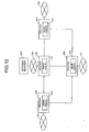
- Fig. 12 is a diagram to explain a conventional network monitoring method.
- Exemplary embodiments of the present invention will be explained in detail below, with reference to the accompanying drawings.
- A conventional network monitoring method will be explained first. Fig. 12 is a diagram to explain the conventional network monitoring method. In the network shown in Fig. 12, a
router 100 is connected to an Internet protocol (IP)network 10a, arouter 200 is connected to anIP network 10b, arouter 300 is connected to anIP network 10c, arouter 400 is connected to anIP network 10d, and therouters 100 to 400 are mesh-connected. - To monitor the network, the
routers 100 to 400 respectively includeSNMP agents 110 to 410, and anetwork manager 500 is connected to theIP network 10a, to integrally manage theSNMP agents 110 to 410. The SNMPagents 110 to 410 obtain the state of the owner apparatus and store the state in an MIB. When the obtained information satisfies a predetermined condition, the SNMP agent notifies this matter to thenetwork manager 500. - The
network manager 500 stores information obtained by regularly making an inquiry to the SNMPagents 110 to 410 and information notified by the SNMPagents 110 to 410 in the owner MIB. Upon detecting a failure, thenetwork manager 500 notifies a network administrator of the occurrence of the failure by displaying a message on a monitor or the like. On receiving the notification of failure, the network administrator operates thenetwork manager 500 to make an inquiry about the details of the failure to the SNMP agent of the communication device with the failure, and handles the failure based on the result of inquiry. - If vendors of the
routers 100 to 400 are different, the MIB stored in theSNMP agents 110 to 410 are different except for the basic part. Therefore, when the network administrator makes an inquiry about the details of the failure to the SNMPagents 110 to 410, the network administrator must know the specifications of the respective MIBs in detail. This imposes a huge burden on the network administrator, and may cause a delay in handling the failure, and increase the damage. - A network monitoring method according to an embodiment will be explained next. Fig. 1 is diagram to explain the network monitoring method according to the embodiment. According to the network monitoring method of the embodiment, a network device is provided between routers as shown in Fig. 1. The network shown in Fig. 1 includes a
network monitoring device 1000a betweenrouters network monitoring device 1000b betweenrouters network monitoring device 1000c betweenrouters routers network monitoring device 1000e betweenrouters - The
network monitoring devices 1000a to 1000e are connected to a network line via a tap, to read all packets flowing in the network. A tap is an apparatus that branches a network signal to extract the signal. Thenetwork monitoring devices 1000a to 1000e then analyze the network state based on a predetermined rule, and if the network state satisfies a certain condition, notify thenetwork manager 500 of occurrence of failure. - On receiving the notification of failure, the network administrator makes an inquiry about the details of the failure to the network monitoring device that is connected to the network having the failure, by operating the
network manager 500, to handle the failure based on the result of the inquiry. Because the product specification of thenetwork monitoring devices 1000a to 1000e are the same, the network administrator can easily make an inquiry about the details even if vendors of therouters 100 to 400 are different. - The configuration of the network monitoring device according to the embodiment will be explained next. Fig. 2 is a functional block diagram of the configuration of the network monitoring device according to the embodiment. Because the
network monitoring devices 1000a to 1000e have the same configuration, thenetwork monitoring device 1000a will be explained as an example. - As shown in Fig. 2, the
network monitoring device 1000a is connected to two-way network lines via atap 2000. Thetap 2000 branches the network line and extracts packets flowing on the network line. In this embodiment, thetap 2000 is independent of thenetwork monitoring device 1000a, but thetap 2000 may be in-built in thenetwork monitoring device 1000a. - The
network monitoring device 1000a analyzes the network based on the packet extracted by thetap 2000, and includes aninterface unit 1100, acontroller 1200, and astorage unit 1300. Theinterface unit 1100 connects to the line branched by thetap 2000 to read the packet. - The
controller 1200 controls the entirenetwork monitoring device 1000a, and includes a searchkey extracting unit 1210, anevent selecting unit 1220, anevent executing unit 1230, afailure determining unit 1240, and a notifyingunit 1250. - The search
key extracting unit 1210 extracts a part of the packet read by theinterface unit 1100. Extraction is performed based on a search key extraction rule stored in a search key extractionrule storage unit 1310 of thestorage unit 1300, and the extracted data is used as a search key for determining how to process the packet. - The search key extraction rule stored in the search key extraction
rule storage unit 1300 will be explained next. Fig. 3 is a diagram of one example of the search key extraction rule. As shown in Fig. 3, the search key extraction rule includes a plurality of entries, and the entries have fields such as type, offset, size, table number, and note. The type indicates the type of packet, which is the subject of the entry, and takes any one value of IP, User Datagram Protocol (UDP), and Transmission Control Protocol (TCP). - The offset column indicates a start position of data to be extracted, and the size column indicates a number of bits of the data to be extracted. The table number column indicates an identification number for identifying the rule for selecting how to process the packet. The rule for selecting how to process the read packet is divided into a plurality of numbers, and is stored in an event selection
rule storage unit 1320 of thestorage unit 1300; the table number shows which rule is to be used. The note column indicates a comment for the entry. The network administrator can edit the search key extraction rule according to need. - When the type is IP, the entry is for all IP packets, and the offset indicates a position from the top of the IP header. Fig. 4 is a structural drawing of the format of the IP header, For example, when a source IP.address (source address) and a destination IP address (destination address) of the IP header are to be extracted, as in the first entry, the offset is set to 96 , and the size is set to 64. When the protocol number is to be extracted, as in the second entry, the offset is set to 72, and the size is set to 8.
- When the type is UDP, the entry is only for IP packets in the UDP, and the offset indicates a position from the top of the UDP header. Fig. 5 is a structural drawing of the format of the UDP header. For example, when a destination port number (destination port) is to be extracted, as in the third entry, the offset is set to 16, and the size is set to 16.
- When the type is TCP, the entry is only for IP packets in the TCP, and the offset indicates a position from the top of the TCP header. Fig. 6 is a structural drawing of the format of the TCP header. For example, when a destination port number (destination port) is to be extracted, as in the fourth entry, the offset is set to 16, and the size is set to 16.
- Thus, the
network monitoring device 1000a according to the embodiment can flexibly set the IP packet to be monitored. For example, when the communication state between particular IP networks is to be monitored, as described above, the type is set to IP, the offset and the size are respectively set to the start portion and the size of the source IP address and the destination IP address. When the state of an IP packet of a particular protocol such as HyperText Transfer Protocol (HTTP) is to be monitored, the type is set to UDP or TCP, as described above, and the offset and the size are respectively set to the start portion and the size of the destination port number. - The
event selecting unit 1220 selects an event to be executed with respect to the packet, by using data extracted by the searchkey extracting unit 1210 as a search key. The event is for a series of steps for processing the packet. Selection of the event is performed based on the event selection rule stored in the event selectionrule storage unit 1320 in thestorage unit 1300, and the selected event is executed by theevent executing unit 1230. - The event selection rule stored in the event selection
rule storage unit 1320 will be explained next. There is one event selection rule for each entry in the search key extraction rule. Figs. 7 to 10 are diagrams of examples of the event selection rule. - Fig. 7 depicts an event selection rule corresponding to the first entry in the search key extraction rule shown in Fig. 3, which is a rule for selectirig an event by the search key used for extracting the source IP address and the destination IP address. As shown in Fig. 7, the event selection rule includes a plurality of entries, and the respective entries have fields such as mask, comparison condition, event name, and last detection time. The network administrator can edit the event selection rule, as required, except the last detection time.
- The mask is for setting a mask value for clearing a part of the search keys, and the value set here is used for obtaining a logical product with the search key. This value is set only when it is necessary. In the example shown in Fig. 7, the mask is used for clearing the low order bits of the source IP address and the low order bits of the destination IP address. Thus, by clearing the low order bits of the IP address, a portion common to the IP network at the source and a portion common to the IP network at the destination, of the source IP address and the destination IP address, can be extracted.
- The comparison condition is data to be compared with the search key. The
event selecting unit 1220 compares the comparison condition with the search key in order from the first entry. If there is an entry, whose comparison condition matches the search key, theevent selecting unit 1220 selects the event set in the entry. The event name indicates a name of an event to be executed. The time when the last match of the comparison condition in the entry with the search key is found is stored as the last detection time. - Thus, by storing the last detection time, the time at which the last IP packet to be monitored has passed through the network line in which the
network monitoring device 1000a is installed can be known, so that the network state can be understood. - For example, when the IP network is mesh-connected as shown in Fig. 1, even if the
network manager 500 perceives that all IP networks are operating normally, communication between the IP networks at the terminal may be blocked. In such a case, as in the example shown in Fig. 7, if there is an entry in which the source IP network address and the destination IP address are designated as the comparison condition in the event selection rule, the respective network monitoring devices are compared, so that a section at which the network is shutdown can be known. - When the last detection time is not updated for a predetermined period, the entry may:be deleted as being unnecessary. With such a configuration, expansion of the event selection rule can be prevented.
- In the first and the second entries.in the example shown in Fig. 7, "traffic count" is specified as the event name. This event is for counting the number of IP packets in which the search key agrees with the comparison condition of the entry. This count may be the total number of cases, or the number of cases for each predetermined period.
- For example, when the quality of a part of the network degrades and the traffic decreases, if there is an entry in which the source IP network address and the destination IP address are designated as the comparison condition in the event selection rule as shown in Fig. 7, a section at which degradation of the network has occurred can be understood, by comparing the counter values in the respective network monitoring devices.
- In the last entry in the example shown in Fig. 7, as the comparison condition is set to "all". This value matches all search keys. Therefore, when the comparison conditions in other entries do not match a search key, the event in this entry is selected at all times. In this entry, an event name is set to "Warning". This event is for notifying the
network manager 500 of detection of a packet, which does not match other entries. - Thus, by registering the warning event in the last entry, the
network manager 500 is notified when an unexpected IP packet is detected. For example, when a packet from an unexpected IP network-is detected, or when a protocol, the use of which is not permitted, is used, this matter can be notified to thenetwork manager 500. - Fig. 8 depicts an event selection rule corresponding to the second entry in the search key extraction rule shown in Fig. 3, which is a rule for selecting an event by the search key used for extracting the protocol number. The first entry in Fig. 8 indicates that when an IP packet in a path control protocol - referred to as Open Shortest Path First (OSPF) - is detected, an event of monitoring a path change is selected. This event is for recording the frequency of the IP packet in the path control protocol and notifying the
network manager 500 when the frequency exceeds a predetermined value. - When the network is unstable, though not completely shutdown, a path between routers changes frequently, and the IP packet in the path control protocol is transferred frequently. By detecting this phenomenon, a sign of failure can be found at an early stage.
- Fig. 9 depicts an event selection rule corresponding to the third entry in the search key extraction rule shown in Fig. 3, which is a rule for selecting an event by the search key used for extracting the destination port number of the IP packet in the UDP. The first entry in Fig. 9 indicates that when an IP packet in the path control protocol - referred to as Routing Information Protocol (RIP) - is detected, an event of monitoring a path change is selected. The second entry indicates that when an IP packet in the HTTP is detected, an event of traffic count is selected.
- Fig. 10 depicts an event selection rule corresponding to the fourth entry in the search key extraction rule shown in Fig. 3, which is a rule for selecting an event by the search key used for extracting the destination port number of the IP packet in the TCP. The first entry in Fig. 10 indicates that when an IP packet in a protocol referred to as TELNET is detected, a capture event is selected. This event is for storing the IP packet as it is.
- By storing the IP packet as it is, the state at the time of occurrence of a failure can be known in detail, thereby enabling quick understanding of the cause and hence, the failure can be dealt with immediately.
- The second entry in Fig. 10 indicates that when an IP packet in a protocol - referred to as Simple Mail Transfer Protocol (SMTP) - is detected, an event of detecting fluctuation is selected. This event is for monitoring fluctuation in the transfer rate of the IP packet, and when the fluctuation exceeds a predetermined value, the fact is notified to the
network manager 500. The transfer rate of the IP packet can be obtained by comparing the transmission time recorded in the IP packet and the current time. - When the network quality degrades and makes the network unstable, the transfer rate of the IP packet fluctuates. By detecting this phenomenon, a sign of a failure can be found at an early stage.
- Referring back to Fig. 2, the
event executing unit 1230 executes the event selected by theevent selecting unit 1220. For example, if the event selected by theevent selecting unit 1220 is "capture", theevent executing unit 1230 stores a packet in acapture buffer 1340 in thestorage unit 1300. - The
failure determining unit 1240 determines whether there is a failure in the network based on the result of the event executed by theevent executing unit 1230. For example, when the event executed by theevent executing unit 1230 is to record the frequency of a packet in the path control protocol, thefailure determining unit 1240 checks if the recorded frequency exceeds a predetermined value, and if the recorded frequency exceeds the predetermined value, thefailure determining unit 1240 determines that there is a failure. When thefailure determining unit 1240 determines that there is a failure, the notifyingunit 1250 notifies thenetwork manager 500 of the occurrence of the failure. - In Fig. 2, a unit with which the
network monitoring device 1000a and thenetwork manager 500 exchange information is not shown, but this unit can be realized by any method. For example, communication may be performed through a network line to be monitored, or may be performed through another wired or wireless line. When another line is used, communication is possible even when a failure occurs in the network to be monitored. Therefore, it is more preferable to use another line than using the network line to be monitored. - The
storage unit 1300 is a memory, for example, and includes the search key extractionrule storage unit 1310, the event selectionrule storage unit 1320, acounter 1330, thecapture buffer 1340, and a settinginformation storage unit 1350. The search key extractionrule storage unit 1310 stores the search key extraction rule, and the event selectionrule storage unit 1320 stores the event selection rule. - The
counter 1330 records the number of IP packets, when the event "traffic count" is executed. Thecapture buffer 1340 stores the IP packet when executing the capture event. The settinginformation storage unit 1350 stores setting information such as a threshold,for determining whether the frequency of the IP packet in the path control protocol is abnormal. - The process procedure of the
network monitoring device 1000a shown in Fig. 2 will be explained below. Fig. 11 is a flowchart of the process procedure of thenetwork monitoring device 1000a shown in Fig. 2. As shown in Fig. 2, in thenetwork monitoring device 1000a, theinterface unit 1100 obtains a packet (step S101), and the searchkey extracting unit 1210 extracts a search key (step S102). - If there no search key is extracted (No at step S103), the process ends. If a search key is extracted (Yes at step S103), the
event selecting unit 1220 selects an event corresponding to the search key (step S104). If there is no event corresponding to the search key (No at step S105), the process returns to step S102, to extract another search key from the packet. - If there is an event corresponding to the search key (Yes at step S105), the
event executing unit 1230 executes the event.. If update of the counter is necessary (Yes at step S106), thecounter 1330 is updated (step S107) . If capture is necessary (Yes at step S108), the IP packet is stored in the capture buffer 1340 (step S109). - The
network monitoring device 1000a then executes other types of event-specific processes (step S110). If thefailure determining unit 1240 determines that a failure has occurred in the network (Yes at step S111), the notifyingunit 1250 notifies thenetwork manager 500 of the occurrence of the failure (step S112). The process returns to step S102, to extract another search key in the packet. - In the embodiment, because the
network monitoring devices 1000a to 1000e monitor the network autonomously, monitoring of the network can be performed even in a network including communication devices having different specifications, without being affected by the difference in the specifications. When thenetwork monitoring devices 1000a to 1000e detect a failure in the network, it is notified to thenetwork manager 500. Therefore, the failure can be handled at an early stage. - According to the present invention, even in a network including communication devices having different specifications, the network monitoring device can monitor the network without being affected by a difference in specifications.
- Moreover, the failure can be handled at an early stage.
- Furthermore, the network analysis can be flexibly changed only by changing the rules.
- Moreover, even when the router or the like seems to be operating normally, a failure can be found at an early stage based on the reception frequency.
- Although the invention has been described with respect to a specific embodiment for a complete and clear disclosure, the appended claims are not to be thus limited but are to be construed as embodying all modifications and alternative constructions that may occur to one skilled in the art that fairly fall within the basic teaching herein set forth.
Claims (10)
- A network monitoring device that monitors a network state, comprising:a receiving unit that receives a packet passing through the network;a processing unit that performs analysis of the network state with respect to the packet received; anda determining unit that determines whether a failure has occurred in the network, based on a result obtained by the processing unit.
- The network monitoring device according to claim 1, further comprising:a notifying unit that notifies an integrated management device of failure, when the determining unit determines that a failure has occurred in the network.
- The network monitoring device according to claim 2, further comprising:an extracting unit that extracts a search key data from the packet, based on a first rule stored in advance in a storage unit; anda searching/selecting unit that searches a second rule stored in advance in the storage unit, using the search key extracted, and selects a process for the packet, based on a result of the search.
- The network monitoring device according to claim 3, wherein
when the second rule includes an entry corresponding to the search key, the searching/selecting unit records the current time in the entry. - The network monitoring device according to claim 1, wherein
the processing unit stores, in the storage unit, a number of packets of the same type as the packet received. - The network monitoring device according to claim 1, wherein
the processing unit records a reception frequency of a packet related to path control, and
the determining unit determines whether a failure has occurred in the network, based on the reception frequency. - The network monitoring device according to claim 1, wherein
the processing unit stores the packet received, in a storage unit. - The network monitoring device according to claim 1, wherein
the processing unit records a transmission rate of the packet, and
the determining unit determines whether a failure has occurred in the network, based on fluctuations in the transmission rate. - The network monitoring device according to claim 3, wherein
when the searching/selecting unit cannot search an entry corresponding to the search key from the second rule, the notifying unit notifies the integrated management device that no entry is found. - A network monitoring method that monitors a network state, comprising:receiving a packet passing through the network;analyzing the network state with respect to the packet received; anddetermining whether a failure has occurred in the network, based on a result obtained at the analyzing.
Applications Claiming Priority (1)
| Application Number | Priority Date | Filing Date | Title |
|---|---|---|---|
| JP2005073475A JP4317828B2 (en) | 2005-03-15 | 2005-03-15 | Network monitoring apparatus and network monitoring method |
Publications (2)
| Publication Number | Publication Date |
|---|---|
| EP1703671A1 true EP1703671A1 (en) | 2006-09-20 |
| EP1703671B1 EP1703671B1 (en) | 2010-12-29 |
Family
ID=34975215
Family Applications (1)
| Application Number | Title | Priority Date | Filing Date |
|---|---|---|---|
| EP20050016396 Expired - Fee Related EP1703671B1 (en) | 2005-03-15 | 2005-07-28 | Device and method for network monitoring |
Country Status (4)
| Country | Link |
|---|---|
| US (1) | US7577098B2 (en) |
| EP (1) | EP1703671B1 (en) |
| JP (1) | JP4317828B2 (en) |
| DE (1) | DE602005025587D1 (en) |
Families Citing this family (16)
| Publication number | Priority date | Publication date | Assignee | Title |
|---|---|---|---|---|
| JP4573780B2 (en) * | 2006-02-02 | 2010-11-04 | 富士通株式会社 | Packet recording / reproducing device |
| JP4367962B2 (en) | 2007-06-19 | 2009-11-18 | インターナショナル・ビジネス・マシーンズ・コーポレーション | Technology for detecting patterns of events that occur in information systems |
| US8527622B2 (en) * | 2007-10-12 | 2013-09-03 | Sap Ag | Fault tolerance framework for networks of nodes |
| KR101547721B1 (en) | 2008-11-27 | 2015-08-26 | 인터내셔널 비지네스 머신즈 코포레이션 | System for assisting with execution of actions in response to detected events, method for assisting with execution of actions in response to detected events, assisting device, and computer program |
| JP4748226B2 (en) * | 2009-02-04 | 2011-08-17 | 沖電気工業株式会社 | Quality degradation detection device, wired wireless judgment device |
| US8472449B2 (en) * | 2010-03-02 | 2013-06-25 | Intrusion, Inc. | Packet file system |
| US9787567B1 (en) | 2013-01-30 | 2017-10-10 | Big Switch Networks, Inc. | Systems and methods for network traffic monitoring |
| US9008080B1 (en) | 2013-02-25 | 2015-04-14 | Big Switch Networks, Inc. | Systems and methods for controlling switches to monitor network traffic |
| US9600263B2 (en) * | 2014-07-21 | 2017-03-21 | Big Switch Networks, Inc. | Systems and methods for performing uninterrupted network upgrades with controllers |
| US10270645B2 (en) | 2014-07-21 | 2019-04-23 | Big Switch Networks, Inc. | Systems and methods for handling link aggregation failover with a controller |
| US9813323B2 (en) | 2015-02-10 | 2017-11-07 | Big Switch Networks, Inc. | Systems and methods for controlling switches to capture and monitor network traffic |
| JP6672751B2 (en) | 2015-12-03 | 2020-03-25 | 富士通株式会社 | Packet collection method, packet collection program, and packet collection device |
| US10685279B2 (en) | 2016-09-26 | 2020-06-16 | Splunk Inc. | Automatically generating field extraction recommendations |
| US10909140B2 (en) | 2016-09-26 | 2021-02-02 | Splunk Inc. | Clustering events based on extraction rules |
| US10257750B2 (en) | 2016-11-15 | 2019-04-09 | Mist Systems, Inc. | Methods and apparatus for capturing and/or using packets to facilitate fault detection |
| US10419327B2 (en) | 2017-10-12 | 2019-09-17 | Big Switch Networks, Inc. | Systems and methods for controlling switches to record network packets using a traffic monitoring network |
Citations (11)
| Publication number | Priority date | Publication date | Assignee | Title |
|---|---|---|---|---|
| US5341363A (en) * | 1991-05-10 | 1994-08-23 | Kabushiki Kaisha Toshiba | Computer system capable of disconnecting itself from a lan |
| US5870540A (en) * | 1995-11-20 | 1999-02-09 | Ncr Corporation | Low overhead method for detecting communication failures on a network |
| US6279037B1 (en) * | 1998-05-28 | 2001-08-21 | 3Com Corporation | Methods and apparatus for collecting, storing, processing and using network traffic data |
| US20020114272A1 (en) * | 2000-12-11 | 2002-08-22 | Cisco Technology, Inc. | Fast failure detection using RTT time considerations on a non-retransmit medium |
| US20030012209A1 (en) * | 2001-07-16 | 2003-01-16 | International Business Machines Corporation | Network access traffic sorter |
| US20030074436A1 (en) * | 2001-10-04 | 2003-04-17 | Adc Broadband Access Systems Inc. | Management information base object model |
| US20030112749A1 (en) * | 2001-12-18 | 2003-06-19 | Brian Hassink | Methods, systems, and computer program products for detecting and/or correcting faults in a multiprotocol label switching network by using redundant paths between nodes |
| US6587432B1 (en) * | 1999-08-31 | 2003-07-01 | Intel Corporation | Method and system for diagnosing network congestion using mobile agents |
| WO2004045143A1 (en) * | 2002-11-13 | 2004-05-27 | Ktfreetel Co., Ltd. | Apparatus for analyzing the packet data on mobile communication network and method thereof |
| US6831893B1 (en) * | 2000-04-03 | 2004-12-14 | P-Cube, Ltd. | Apparatus and method for wire-speed classification and pre-processing of data packets in a full duplex network |
| US20050021715A1 (en) * | 2003-05-21 | 2005-01-27 | Diego Dugatkin | Automated capturing and characterization of network traffic using feedback |
Family Cites Families (18)
| Publication number | Priority date | Publication date | Assignee | Title |
|---|---|---|---|---|
| DE69027531D1 (en) * | 1990-09-28 | 1996-07-25 | Ibm | Data transmission unit (DCE) with a clock arrangement controlled by a processing means |
| US5453982A (en) * | 1994-08-29 | 1995-09-26 | Hewlett-Packard Company | Packet control procedure between a host processor and a peripheral unit |
| JPH1132017A (en) * | 1997-07-11 | 1999-02-02 | Fujitsu Ltd | Pm parameter processing unit for transmitter |
| IL121898A0 (en) | 1997-10-07 | 1998-03-10 | Cidon Israel | A method and apparatus for active testing and fault allocation of communication networks |
| US6574197B1 (en) * | 1998-07-03 | 2003-06-03 | Mitsubishi Denki Kabushiki Kaisha | Network monitoring device |
| JP2000151606A (en) | 1998-11-16 | 2000-05-30 | Nec Corp | Network monitoring system, network monitoring method, network management device, network device to be managed and recording medium |
| JP2001036563A (en) | 1999-07-22 | 2001-02-09 | Nec Eng Ltd | Fault detection and analysis system |
| JP2001069173A (en) | 1999-08-31 | 2001-03-16 | Hitachi Cable Ltd | Packet filter mechanism |
| US6868062B1 (en) * | 2000-03-28 | 2005-03-15 | Intel Corporation | Managing data traffic on multiple ports |
| JP2001337873A (en) | 2000-05-26 | 2001-12-07 | Nec Corp | Fault supervision system |
| JP2002354012A (en) | 2001-05-28 | 2002-12-06 | Kddi Research & Development Laboratories Inc | Network monitoring system |
| JP2003023464A (en) | 2001-07-11 | 2003-01-24 | Kddi Corp | Packet collection storage system having time information |
| JP3609763B2 (en) | 2001-08-17 | 2005-01-12 | 三菱電機インフォメーションシステムズ株式会社 | Route control system, route control method, and program for causing computer to execute the same |
| JP2003069567A (en) | 2001-08-24 | 2003-03-07 | Nec System Technologies Ltd | System and method for monitoring network to notify |
| JP3886432B2 (en) | 2002-09-17 | 2007-02-28 | 沖電気工業株式会社 | Routing processing device and packet type identification device |
| JP2005033289A (en) | 2003-07-08 | 2005-02-03 | Nippon Telegr & Teleph Corp <Ntt> | Testing method in ip service, and system thereof |
| WO2005036864A1 (en) | 2003-10-06 | 2005-04-21 | Preformed Line Products Company | Fiber to the home demarcation enclosure |
| US20060259620A1 (en) | 2003-10-10 | 2006-11-16 | Hiroaki Tamai | Statistical information collecting method and apparatus |
-
2005
- 2005-03-15 JP JP2005073475A patent/JP4317828B2/en not_active Expired - Fee Related
- 2005-07-26 US US11/189,400 patent/US7577098B2/en not_active Expired - Fee Related
- 2005-07-28 DE DE200560025587 patent/DE602005025587D1/en active Active
- 2005-07-28 EP EP20050016396 patent/EP1703671B1/en not_active Expired - Fee Related
Patent Citations (11)
| Publication number | Priority date | Publication date | Assignee | Title |
|---|---|---|---|---|
| US5341363A (en) * | 1991-05-10 | 1994-08-23 | Kabushiki Kaisha Toshiba | Computer system capable of disconnecting itself from a lan |
| US5870540A (en) * | 1995-11-20 | 1999-02-09 | Ncr Corporation | Low overhead method for detecting communication failures on a network |
| US6279037B1 (en) * | 1998-05-28 | 2001-08-21 | 3Com Corporation | Methods and apparatus for collecting, storing, processing and using network traffic data |
| US6587432B1 (en) * | 1999-08-31 | 2003-07-01 | Intel Corporation | Method and system for diagnosing network congestion using mobile agents |
| US6831893B1 (en) * | 2000-04-03 | 2004-12-14 | P-Cube, Ltd. | Apparatus and method for wire-speed classification and pre-processing of data packets in a full duplex network |
| US20020114272A1 (en) * | 2000-12-11 | 2002-08-22 | Cisco Technology, Inc. | Fast failure detection using RTT time considerations on a non-retransmit medium |
| US20030012209A1 (en) * | 2001-07-16 | 2003-01-16 | International Business Machines Corporation | Network access traffic sorter |
| US20030074436A1 (en) * | 2001-10-04 | 2003-04-17 | Adc Broadband Access Systems Inc. | Management information base object model |
| US20030112749A1 (en) * | 2001-12-18 | 2003-06-19 | Brian Hassink | Methods, systems, and computer program products for detecting and/or correcting faults in a multiprotocol label switching network by using redundant paths between nodes |
| WO2004045143A1 (en) * | 2002-11-13 | 2004-05-27 | Ktfreetel Co., Ltd. | Apparatus for analyzing the packet data on mobile communication network and method thereof |
| US20050021715A1 (en) * | 2003-05-21 | 2005-01-27 | Diego Dugatkin | Automated capturing and characterization of network traffic using feedback |
Also Published As
| Publication number | Publication date |
|---|---|
| DE602005025587D1 (en) | 2011-02-10 |
| US20060209699A1 (en) | 2006-09-21 |
| US7577098B2 (en) | 2009-08-18 |
| JP2006261804A (en) | 2006-09-28 |
| EP1703671B1 (en) | 2010-12-29 |
| JP4317828B2 (en) | 2009-08-19 |
Similar Documents
| Publication | Publication Date | Title |
|---|---|---|
| US7577098B2 (en) | Device and method for network monitoring | |
| EP1999890B1 (en) | Automated network congestion and trouble locator and corrector | |
| JP4255366B2 (en) | Network monitoring program, network monitoring method, and network monitoring apparatus | |
| US7832010B2 (en) | Unauthorized access program monitoring method, unauthorized access program detecting apparatus, and unauthorized access program control apparatus | |
| US8830850B2 (en) | Network monitoring device, network monitoring method, and network monitoring program | |
| US20080114581A1 (en) | Root cause analysis approach with candidate elimination using network virtualization | |
| US20070177523A1 (en) | System and method for network monitoring | |
| US11178114B2 (en) | Data processing method, device, and system | |
| JP5066544B2 (en) | Incident monitoring device, method, and program | |
| CN111935172A (en) | Network abnormal behavior detection method based on network topology, computer device and computer readable storage medium | |
| CN112202609A (en) | Industrial control asset detection method and device, electronic equipment and storage medium | |
| JP2005285040A (en) | Network monitoring system, method and program | |
| US6954785B1 (en) | System for identifying servers on network by determining devices that have the highest total volume data transfer and communication with at least a threshold number of client devices | |
| US7266088B1 (en) | Method of monitoring and formatting computer network data | |
| JP2006332997A (en) | Communication management device, network system, communication disconnecting method, and program | |
| KR100432168B1 (en) | Multiple Intrusion Detection Objects in Security Gateway System for Network Intrusion Detection | |
| KR100887874B1 (en) | System for managing fault of internet and method thereof | |
| JP2004336658A (en) | Network monitoring method and network monitoring apparatus | |
| CN112165409A (en) | Port management method, system, device and readable storage medium | |
| CN105743875A (en) | Information Processing Device, Method, And Medium | |
| CN117376282B (en) | Switch view display method, device and computer readable storage medium | |
| CN116208431B (en) | Industrial control network flow abnormality detection method, system, device and readable medium | |
| CN108111812B (en) | Video safety monitoring method and monitoring system | |
| JP4361570B2 (en) | Packet control instruction management method | |
| JP2007006383A (en) | Communication managing apparatus, identification system and method for unauthorized communication terminal apparatus, and program |
Legal Events
| Date | Code | Title | Description |
|---|---|---|---|
| PUAI | Public reference made under article 153(3) epc to a published international application that has entered the european phase |
Free format text: ORIGINAL CODE: 0009012 |
|
| AK | Designated contracting states |
Kind code of ref document: A1 Designated state(s): AT BE BG CH CY CZ DE DK EE ES FI FR GB GR HU IE IS IT LI LT LU LV MC NL PL PT RO SE SI SK TR |
|
| AX | Request for extension of the european patent |
Extension state: AL BA HR MK YU |
|
| 17P | Request for examination filed |
Effective date: 20061130 |
|
| AKX | Designation fees paid |
Designated state(s): DE FR GB |
|
| 17Q | First examination report despatched |
Effective date: 20071213 |
|
| GRAP | Despatch of communication of intention to grant a patent |
Free format text: ORIGINAL CODE: EPIDOSNIGR1 |
|
| GRAS | Grant fee paid |
Free format text: ORIGINAL CODE: EPIDOSNIGR3 |
|
| GRAA | (expected) grant |
Free format text: ORIGINAL CODE: 0009210 |
|
| AK | Designated contracting states |
Kind code of ref document: B1 Designated state(s): DE FR GB |
|
| REG | Reference to a national code |
Ref country code: GB Ref legal event code: FG4D |
|
| REF | Corresponds to: |
Ref document number: 602005025587 Country of ref document: DE Date of ref document: 20110210 Kind code of ref document: P |
|
| REG | Reference to a national code |
Ref country code: DE Ref legal event code: R096 Ref document number: 602005025587 Country of ref document: DE Effective date: 20110210 |
|
| PLBE | No opposition filed within time limit |
Free format text: ORIGINAL CODE: 0009261 |
|
| STAA | Information on the status of an ep patent application or granted ep patent |
Free format text: STATUS: NO OPPOSITION FILED WITHIN TIME LIMIT |
|
| 26N | No opposition filed |
Effective date: 20110930 |
|
| REG | Reference to a national code |
Ref country code: DE Ref legal event code: R097 Ref document number: 602005025587 Country of ref document: DE Effective date: 20110930 |
|
| REG | Reference to a national code |
Ref country code: FR Ref legal event code: PLFP Year of fee payment: 11 |
|
| PGFP | Annual fee paid to national office [announced via postgrant information from national office to epo] |
Ref country code: DE Payment date: 20150722 Year of fee payment: 11 Ref country code: GB Payment date: 20150722 Year of fee payment: 11 |
|
| PGFP | Annual fee paid to national office [announced via postgrant information from national office to epo] |
Ref country code: FR Payment date: 20150629 Year of fee payment: 11 |
|
| REG | Reference to a national code |
Ref country code: DE Ref legal event code: R119 Ref document number: 602005025587 Country of ref document: DE |
|
| GBPC | Gb: european patent ceased through non-payment of renewal fee |
Effective date: 20160728 |
|
| PG25 | Lapsed in a contracting state [announced via postgrant information from national office to epo] |
Ref country code: FR Free format text: LAPSE BECAUSE OF NON-PAYMENT OF DUE FEES Effective date: 20160801 Ref country code: DE Free format text: LAPSE BECAUSE OF NON-PAYMENT OF DUE FEES Effective date: 20170201 |
|
| REG | Reference to a national code |
Ref country code: FR Ref legal event code: ST Effective date: 20170331 |
|
| PG25 | Lapsed in a contracting state [announced via postgrant information from national office to epo] |
Ref country code: GB Free format text: LAPSE BECAUSE OF NON-PAYMENT OF DUE FEES Effective date: 20160728 |