EP1705043A2 - Side impact beam for a vehicle - Google Patents
Side impact beam for a vehicle Download PDFInfo
- Publication number
- EP1705043A2 EP1705043A2 EP06004730A EP06004730A EP1705043A2 EP 1705043 A2 EP1705043 A2 EP 1705043A2 EP 06004730 A EP06004730 A EP 06004730A EP 06004730 A EP06004730 A EP 06004730A EP 1705043 A2 EP1705043 A2 EP 1705043A2
- Authority
- EP
- European Patent Office
- Prior art keywords
- side impact
- impact beam
- insert
- beam according
- carrier part
- Prior art date
- Legal status (The legal status is an assumption and is not a legal conclusion. Google has not performed a legal analysis and makes no representation as to the accuracy of the status listed.)
- Granted
Links
- 229910000831 Steel Inorganic materials 0.000 claims description 20
- 239000010959 steel Substances 0.000 claims description 20
- 239000004033 plastic Substances 0.000 claims description 10
- 229920003023 plastic Polymers 0.000 claims description 10
- 238000003466 welding Methods 0.000 claims description 4
- 239000002990 reinforced plastic Substances 0.000 claims description 3
- 239000002184 metal Substances 0.000 claims description 2
- 230000037431 insertion Effects 0.000 abstract 5
- 238000003780 insertion Methods 0.000 abstract 5
- 239000000463 material Substances 0.000 description 5
- 238000005452 bending Methods 0.000 description 4
- 239000002984 plastic foam Substances 0.000 description 3
- 239000004952 Polyamide Substances 0.000 description 2
- 238000011161 development Methods 0.000 description 2
- 230000018109 developmental process Effects 0.000 description 2
- 229920002647 polyamide Polymers 0.000 description 2
- 229920005830 Polyurethane Foam Polymers 0.000 description 1
- 238000010521 absorption reaction Methods 0.000 description 1
- 239000000853 adhesive Substances 0.000 description 1
- 230000001070 adhesive effect Effects 0.000 description 1
- 230000006835 compression Effects 0.000 description 1
- 238000007906 compression Methods 0.000 description 1
- 238000005336 cracking Methods 0.000 description 1
- 238000013461 design Methods 0.000 description 1
- 238000006073 displacement reaction Methods 0.000 description 1
- 239000003365 glass fiber Substances 0.000 description 1
- 238000004519 manufacturing process Methods 0.000 description 1
- 238000005259 measurement Methods 0.000 description 1
- 238000000034 method Methods 0.000 description 1
- 238000005457 optimization Methods 0.000 description 1
- 230000002028 premature Effects 0.000 description 1
- 238000012360 testing method Methods 0.000 description 1
Images


Classifications
-
- B—PERFORMING OPERATIONS; TRANSPORTING
- B60—VEHICLES IN GENERAL
- B60J—WINDOWS, WINDSCREENS, NON-FIXED ROOFS, DOORS, OR SIMILAR DEVICES FOR VEHICLES; REMOVABLE EXTERNAL PROTECTIVE COVERINGS SPECIALLY ADAPTED FOR VEHICLES
- B60J5/00—Doors
- B60J5/04—Doors arranged at the vehicle sides
- B60J5/042—Reinforcement elements
- B60J5/0422—Elongated type elements, e.g. beams, cables, belts or wires
- B60J5/0438—Elongated type elements, e.g. beams, cables, belts or wires characterised by the type of elongated elements
- B60J5/0443—Beams
- B60J5/0444—Beams characterised by a special cross section
Abstract
Description
Die Erfindung betrifft einen Seitenaufprallträger für ein Kraftfahrzeug. Der Seitenaufprallträger umfaßt ein Trägerteil, das ein geschlossenes Profil aufweist.The invention relates to a side impact beam for a motor vehicle. The side impact beam includes a support member having a closed profile.
Derartige Seitenaufprallträger sind bereits bekannt. Sie werden bei Seitentüren von Kraftfahrzeugen verwendet. Allerdings können sie auch bei anderen Bauteilen eines Kraftfahrzeugs Verwendung finden, insbesondere bei Karosseriebauteilen oder Klappen, insbesondere Heckklappen, von Kraftfahrzeugen. Das Trägerteil ist vorzugsweise aus Metall, insbesondere aus Stahl. Es weist ein Hohlprofil auf. Das Profil kann auch annähernd geschlossen sein. Aus Festigkeitsgründen ist allerdings in den meisten Fällen ein vollständig geschlossenes Profil vorteilhaft oder erforderlich.Such side impact beams are already known. They are used on side doors of motor vehicles. However, they can also be used in other components of a motor vehicle, in particular in the case of body components or flaps, in particular tailgates, of motor vehicles. The carrier part is preferably made of metal, in particular of steel. It has a hollow profile. The profile can also be approximately closed. For reasons of strength, however, a completely closed profile is in most cases advantageous or necessary.
Die
Aus der
Aufgabe der Erfindung ist es, einen verbesserten Seitenaufprallträger der eingangs angegebenen Art vorzuschlagen.The object of the invention is to propose an improved side impact beam of the type specified.
Erfindungsgemäß wird diese Aufgabe durch die kennzeichnenden Merkmale des Anspruchs 1 gelöst. In dem Trägerteil ist ein Einlegeteil vorgesehen. Hierdurch kann eine erhebliche Steigerung der Festigkeit des Seitenaufprallträgers erreicht werden. Vorzugsweise hat das Einlegeteil eine niedrigere Festigkeit als das Trägerteil. Das Einlegeteil kann in das Trägerteil eingelegt werden. Es kann allerdings auch anderweitig in das Trägerteil eingebracht werden. Dabei kann zunächst das Trägerteil hergestellt und anschließend das Einlegeteil eingelegt oder anderweitig eingebracht werden. Es ist allerdings auch möglich, Trägerteil und Einlegeteil gleichzeitig herzustellen.According to the invention this object is achieved by the characterizing features of
Vorteilhafte Weiterbildungen der Erfindung sind in den Unteransprüchen beschrieben.Advantageous developments of the invention are described in the subclaims.
Das Einlegeteil kann sich über die gesamte Länge des Trägerteils erstrecken. Es kann allerdings auch vorteilhaft sein, wenn sich das Einlegeteil über einen Teilbereich des Trägerteils erstreckt. Vorzugsweise liegt dieser Teilbereich in der Mitte des Trägerteils.The insert may extend over the entire length of the support member. However, it may also be advantageous if the insert extends over a portion of the support member. Preferably, this portion is located in the middle of the support member.
Eine weitere vorteilhafte Weiterbildung ist dadurch gekennzeichnet, daß das Einlegeteil mit dem Trägerteil nicht schubfest verbunden ist. Die Verbindung ist vorzugsweise derart, daß bei einer Biegebelastung des Seitenaufprallträgers eine Relativbewegung zwischen dem Trägerteil und dem Einlegeteil möglich ist.A further advantageous embodiment is characterized in that the insert is not connected to the support member shudder. The connection is preferably such that a relative movement between the carrier part and the insert part is possible with a bending load of the side impact carrier.
Das Einlegeteil kann in seiner Position zum Trägerteil gesichert sein. Insbesondere kann das Einlegeteil mit dem Trägerteil verklebt sein. Dabei kann die Sicherung bzw. Verklebung derart ausgestaltet sein, daß eine Relativbewegung zwischen Einlegeteil und Trägerteil bei einer Biegebelastung des Seitenaufprallträgers möglich ist.The insert may be secured in position to the support member. In particular, the insert may be glued to the support member. In this case, the fuse or adhesive bond can be designed such that a relative movement between the insert part and the carrier part is possible with a bending load of the side impact carrier.
Das Einlegeteil kann das Profil des Trägerteils vollständig ausfüllen. Es kann allerdings auch vorteilhaft sein, wenn das Einlegeteil das Profil des Trägerteils teilweise ausfüllt.The insert can completely fill the profile of the carrier part. However, it may also be advantageous if the insert partially fills the profile of the support member.
Vorzugsweise ist das Einlegeteil aus Kunststoff. Besonders geeignet ist PA (Polyamid). Es können allerdings auch andere Kunststoffe verwendet werden, beispielsweise PET.Preferably, the insert is made of plastic. Particularly suitable is PA (polyamide). However, other plastics can also be used, for example PET.
Eine weitere vorteilhafte Weiterbildung ist dadurch gekennzeichnet, daß das Einlegeteil aus nicht verstärktem Kunststoff ist. Insbesondere handelt es sich bei dem nicht verstärkten Kunststoff um einen Kunststoff, der keinen Glasfaseranteil und/oder keinen Anteil aus Kunststoffschaum aufweist.A further advantageous development is characterized in that the insert is made of non-reinforced plastic. In particular, the non-reinforced plastic is a plastic which has no glass fiber content and / or no share of plastic foam.
Vorteilhaft ist es, wenn das Einlegeteil temperaturbeständig ist. Das Einlegeteil ist vorzugsweise aus einem temperaturbeständigen Kunststoff hergestellt.It is advantageous if the insert is temperature resistant. The insert is preferably made of a temperature-resistant plastic.
Das Trägerteil ist vorzugsweise aus Stahl hergestellt. Vorteilhaft ist es, wenn der Stahl eine Zugfestigkeit von mindestens 800 N/mm2 aufweist. In bestimmten Anwendungsfällen kann es vorteilhaft sein, wenn der Stahl eine höhere Zugfestigkeit aufweist, insbesondere eine Zugfestigkeit von mindestens 1000 N/mm2.The support member is preferably made of steel. It is advantageous if the steel has a tensile strength of at least 800 N / mm 2 . In certain applications, it may be advantageous if the steel has a higher tensile strength, in particular a tensile strength of at least 1000 N / mm 2 .
Eine weitere vorteilhafte Weiterbildung ist dadurch gekennzeichnet, daß das Trägerteil durch Rollprofilieren hergestellt ist. Ferner ist es in bestimmten Fällen vorteilhaft, wenn das Trägerteil durch Schweißen hergestellt ist, insbesondere durch Laserschweißen.A further advantageous embodiment is characterized in that the carrier part is produced by roll profiling. Furthermore, it is advantageous in certain cases if the carrier part is produced by welding, in particular by laser welding.
Nach einer weiteren vorteilhaften Weiterbildung weist das Trägerteil einen konstanten Querschnitt auf. In diesem Fall, aber auch dann, wenn das Trägerteil keinen konstanten Querschnitt aufweist, kann es vorteilhaft sein, wenn das Einlegeteil einen konstanten Querschnitt aufweist. Wenn der Querschnitt über die Länge des Trägerteils bzw. des Einlegeteils konstant ist, können sich Vorteile, insbesondere Vereinfachungen, bei der Herstellung ergeben.According to a further advantageous embodiment, the carrier part has a constant cross-section. In this case, but also if the carrier part does not have a constant cross section, it can be advantageous if the insert part has a constant cross section. If the cross-section over the length of the support member or the insert is constant, there may be advantages, in particular simplifications, in the production.
Ausführungsbeispiele der Erfindung werden nachstehend anhand der beigefügten Zeichnung im einzelnen erläutert. In der Zeichnung zeigt
- Fig. 1
- eine Rohbautür eines Kraftfahrzeugs in einer Seitenansicht von innen,
- Fig. 2
- einen Seitenaufprallträger in einer perspektivischen Ansicht,
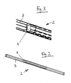
- Fig. 3
- eine vergrößerte Teilansicht des Seitenaufprallträgers gemäß Fig. 2,
- Fig. 4
- den Seitenaufprallträger in einer vergrößerten perspektivischen Ansicht,
- Fig. 5
- das Profil des Seitenaufprallträgers und
- Fig. 6
- einen abgewandelten Seitenaufprallträger in einer Profilansicht.
- Fig. 1
- a shell door of a motor vehicle in a side view from the inside,
- Fig. 2
- a side impact beam in a perspective view,
- Fig. 3
- an enlarged partial view of the side impact beam according to FIG. 2,
- Fig. 4
- the side impact beam in an enlarged perspective view,
- Fig. 5
- the profile of the side impact beam and
- Fig. 6
- a modified side impact beam in a profile view.
Die in Fig. 1 gezeigte Kraftfahrzeug-Rohbautür umfaßt einen Türkasten 1, in dem ein Seitenaufprallträger 2 vorgesehen ist, der im wesentlichen in FahrzeugLängsrichtung verläuft. Der Seitenaufprallträger 2 ist im unteren Bereich des Türkastens 1 vorgesehen. Er verläuft von vorne nach hinten leicht ansteigend.The motor vehicle body door shown in Fig. 1 comprises a
Wie aus Fig. 2 bis 5 ersichtlich, umfaßt der Seitenaufprallträger 2 ein Trägerteil 3, das ein geschlossenes Profil aufweist, und ein Einlegeteil 4, das in dem Trägerteil 3 vorgesehen ist. Das Trägerteil 3 ist aus Stahl hergestellt. Sein Profil entspricht im wesentlichen demjenigen nach der
Das Einlegeteil 4 ist aus Kunststoff hergestellt. Es erstreckt sich über einen Teilbereich des Trägerteils 3, nämlich beidseits der Mitte dieses Trägerteils 3. Die Länge des Einlegeteils 4 beträgt etwa ein Viertel bis ein Drittel der Länge des Trägerteils 3.The
Ferner füllt das Einlegeteil 4 das Profil des Trägerteils 3 vollständig aus, wie insbesondere aus Fig. 5 ersichtlich.Furthermore, the
Bei der in Fig. 6 gezeigten, abgewandelten Ausführungsform wird das Profil des Trägerteils 3 von dem Einlegeteil 4 nur teilweise ausgefüllt. Das Profil des Trägerteils 3 entspricht im wesentlichen demjenigen der ersten Ausführungsform nach Fig. 2 bis 5. Das Einlegeteil 3 weist einen rechteckigen Querschnitt auf. Es ist an einer Schmalseite mit der Innenseite des Druckgurtes 6 des Profils des Trägerteils 3 verbunden, nämlich verklebt. Die gegenüberliegende Schmalseite des Einlegeteils 3 weist einen geringfügigen Abstand zum Zuggurt 5 des Profils des Trägerteils 3 auf. Die seitlichen Stege 7, 8 des Profils des Trägerteils 3, die nach innen konkav gekrümmt sind, sind von den Längsseiten des Einlegeteils 4 beabstandet.In the modified embodiment shown in FIG. 6, the profile of the
Durch die Erfindung wird ein verbesserter Seitenaufprallträger für Kraftfahrzeuge geschaffen. Das Einlegeteil kann auch als Inlay bzw. Kunststoff-Inlay bezeichnet werden. Die Länge des Einlegeteils kann im Verhältnis zum Trägerteil je nach spezifischer Lastenheftanforderung festgelegt werden. Das Einlegeteil wird vorzugsweise im mittleren Bereich des Seitenaufprallträgers positioniert. Es kann dort mit oder ohne Schubverbund zum Trägerteil befestigt werden. Je nach Auslegungswunsch für die Lastanforderung kann dabei die spezielle Materialart bzw. Kunststoffart sowie die spezielle Inlay-Geometrie derart gewählt werden, daß die spezifische Lastanforderung, insbesondere das Kraft-Weg-Verhalten im Crash-Fall, das Gesamtgewicht und/oder die Temperaturbeständigkeit, erfüllt wird.The invention provides an improved side impact beam for motor vehicles. The insert can also be referred to as inlay or plastic inlay. The length of the insert can be determined in relation to the support part according to the specific requirement specification. The insert is preferably positioned in the central region of the side impact beam. It can be there with you or be attached to the carrier part without shear connection. Depending on the design request for the load request, the special type of material or type of plastic and the special inlay geometry can be selected such that the specific load requirement, in particular the force-displacement behavior in the event of a crash, the total weight and / or the temperature resistance becomes.
Als Kunststoffmaterial für das Einlegeteil ist PA (Polyamid) besonders geeignet, da es besondere Anforderungen hinsichtlich Zugfestigkeit und Temperaturbeständigkeit erfüllt. Grundsätzlich können allerdings auch andere Kunststoffe verwendet werden. Aus Testmessungen ergibt sich, daß nicht-verstärktes PA und PET gute Ergebnisse liefern.As a plastic material for the insert PA (polyamide) is particularly suitable because it meets special requirements in terms of tensile strength and temperature resistance. In principle, however, other plastics can be used. From test measurements, unamplified PA and PET give good results.
Durch das Einbringen des Einlegeteils in das ursprünglich leere Profil, beispielsweise aus hochfestem Stahl wie z.B. Docol DP 1200, wird verhindert, daß es bei bestimmten Crash-Anforderungen, die insbesondere an die US-Norm FMVSS 214 angelehnt sind, zu frühzeitigen Bauteilinstabilitäten (Knicken) und damit zu Bauteilversagen in Form von Rißbildung und darauf folgendem Bruch des Profils bzw. Stahlprofils kommt. Dieses ungünstige Verhalten tritt ohne Einlegeteil insbesondere bei dünnwandigen hochfesten Stählen auf und ist für diese aufgrund ihrer relativ geringen Bruchfestigkeit im Vergleich zu mittelfesten bzw. weichen Stählen geradezu charakteristisch. Andererseits bietet hochfester Stahl mit Zugfestigkeiten ≥ 1000 MPa im Vergleich zu weniger hochfesten Stählen den großen Vorteil eines anfänglich sehr hoch verlaufenden Kraftniveaus und damit einer hohen anfänglichen Energieabsorption im Falle eines Seitenaufpralls nach FMVSS 214 (quasistatische Biegung durch einen zylinderförmigen Stempel mit Durchmesser 300 oder 305 mm gemäß Lastenheftanforderung vieler OEMs). Dieses wird durch hochfeste Stähle schon bei geringen Blechstärken gewährleistet und bietet daher große Vorteile hinsichtlich der Gewichts- und Kostenoptimierung.By inserting the insert into the originally empty profile, for example made of high-strength steel such. Docol DP 1200, it is prevented for certain crash requirements, which are particularly based on the US standard FMVSS 214, to premature component instability (kinking) and thus to component failure in the form of cracking and subsequent breakage of the profile or steel profile comes. This unfavorable behavior occurs without insert, especially in thin-walled high-strength steels and is downright characteristic of these due to their relatively low breaking strength compared to medium-hard or soft steels. On the other hand, high strength steel with tensile strengths ≥ 1000 MPa offers the great advantage of an initially very high force level and thus high initial energy absorption in the event of a side impact according to FMVSS 214 (quasi-static bending by a 300 or 305 mm diameter cylindrical punch according to specifications of many OEMs). This is ensured by high-strength steels even at low sheet thicknesses and therefore offers great advantages in terms of weight and cost optimization.
Wenn anstelle eines Einlegeteils das Bauteilversagen durch eine Erhöhung der Stahlblechdicke zu erreichen versucht würde, würde dies die genannten Gewichts-und Kostenvorteile zunichte machen, soweit es überhaupt möglich wäre, da die gegenwärtig verfügbare Blechstärke der hochfesten Stähle auf Dicken um 2 mm beschränkt ist. Durch die Erfindung kann erreicht werden, daß die großen Vorteile der hochfesten Stähle geringer Blechstärke nicht durch den Nachteil des frühzeitigen Materialversagens bei geringen Verformungswegen eingebüßt werden.If, instead of an insert, the component failure would be attempted by increasing the steel plate thickness, this would destroy the weight and cost advantages mentioned, if at all possible, since the Currently available sheet thickness of high-strength steels is limited to thicknesses of 2 mm. By the invention can be achieved that the great advantages of high-strength steels low plate thickness are not lost by the disadvantage of early material failure at low deformation paths.
Die Erfindung ist für Seitenaufprallträger und andere Strukturteile mit überwiegender Biegebeanspruchung geeignet. Als Material für das Trägerteil werden vorzugsweise hochfeste Stähle mit einer minimalen Zugfestigkeit von 800 N/mm2 verwendet. In bestimmten Fällen ist es vorteilhaft, hochfeste Stähle mit einer höheren minimalen Zugfestigkeit zu verwenden, insbesondere mit einer minimalen Zugfestigkeit von 1000 N/mm2. Das Trägerteil kann rollprofiliert oder geschweißt, inbesondere lasergeschweißt, sein. Ferner kann es vorteilhaft sein, wenn der hochfeste Stahl eine Blechstärke von höchstens 2 mm aufweist. Insbesondere können hochfeste Stähle mit einer Blechstärke von 1 mm bis 2 mm verwendet werden.The invention is suitable for side impact beams and other structural parts with predominantly bending stress. As the material for the support member, high-strength steels having a minimum tensile strength of 800 N / mm 2 are preferably used. In certain cases, it is advantageous to use high strength steels having a higher minimum tensile strength, particularly with a minimum tensile strength of 1000 N / mm 2 . The support member may be roll profiled or welded, in particular laser welded, be. Furthermore, it may be advantageous if the high-strength steel has a sheet thickness of at most 2 mm. In particular, high-strength steels with a sheet thickness of 1 mm to 2 mm can be used.
Claims (11)
dadurch gekennzeichnet,
daß in dem Trägerteil (3) ein Einlegeteil (4) vorgesehen ist.Side impact beam for a motor vehicle with a support part (3) having a closed profile,
characterized,
in that an insert part (4) is provided in the carrier part (3).
Applications Claiming Priority (2)
| Application Number | Priority Date | Filing Date | Title |
|---|---|---|---|
| DE102005012981 | 2005-03-21 | ||
| DE102005036292A DE102005036292B4 (en) | 2005-03-21 | 2005-08-02 | Side impact beam for a motor vehicle |
Publications (3)
| Publication Number | Publication Date |
|---|---|
| EP1705043A2 true EP1705043A2 (en) | 2006-09-27 |
| EP1705043A3 EP1705043A3 (en) | 2008-12-10 |
| EP1705043B1 EP1705043B1 (en) | 2011-10-19 |
Family
ID=36390248
Family Applications (1)
| Application Number | Title | Priority Date | Filing Date |
|---|---|---|---|
| EP06004730A Expired - Fee Related EP1705043B1 (en) | 2005-03-21 | 2006-03-08 | Side impact beam for a vehicle |
Country Status (4)
| Country | Link |
|---|---|
| US (1) | US7497504B2 (en) |
| EP (1) | EP1705043B1 (en) |
| JP (1) | JP5021947B2 (en) |
| DE (1) | DE102005036292B4 (en) |
Cited By (1)
| Publication number | Priority date | Publication date | Assignee | Title |
|---|---|---|---|---|
| DE102009034080A1 (en) | 2009-04-01 | 2010-10-14 | Dura Automotive Body & Glass Systems Gmbh | Side impact support for door or flap of motor vehicle, has hook component which is hooked with body component, where hook component is formed as hooks and elevation, particularly as pivot |
Families Citing this family (15)
| Publication number | Priority date | Publication date | Assignee | Title |
|---|---|---|---|---|
| JP4388340B2 (en) * | 2003-10-03 | 2009-12-24 | 新日本製鐵株式会社 | Strength members for automobiles |
| DE102007063537A1 (en) * | 2007-12-21 | 2009-07-02 | Deutsches Zentrum für Luft- und Raumfahrt e.V. | Side door reinforcement device for vehicle i.e. car, has reinforcement element forming peripheral side closed hollow section together with peripheral-side opened profile element section of profile element |
| DE102008015960B4 (en) * | 2008-03-20 | 2012-01-12 | Deutsches Zentrum für Luft- und Raumfahrt e.V. | Vehicle having at least one energy absorption device for absorbing impact energy |
| DE102008022754A1 (en) * | 2008-05-08 | 2009-11-19 | Trw Airbag Systems Gmbh | Vehicle safety system, has hollow vehicle structural component partly filled or externally coated with aerogel, where vehicle structural component is section of bumper, vehicle frame, side panel or side door |
| US8727421B2 (en) | 2011-08-31 | 2014-05-20 | Shape Corp. | Door beam assembly with roll formed beam |
| DE102012005872A1 (en) | 2012-03-23 | 2012-11-08 | Daimler Ag | Carrier i.e. side impact carrier, for installation at side door of passenger car, has spacer ribs arranged at outer surface of reinforcement elements for supporting reinforcement elements on inner surface of carrier section |
| DE102012012808A1 (en) | 2012-06-28 | 2014-01-02 | Daimler Ag | Side door for motor vehicle e.g. passenger car, has door interior portion that is reinforced at regions by shell element so as to form hollow section |
| DE102012012811A1 (en) | 2012-06-28 | 2012-12-20 | Daimler Ag | Side impact support for side door of passenger car, is provided with support profile over length region of receiving chamber, and reinforcement element |
| DE102012014385A1 (en) | 2012-07-20 | 2013-03-21 | Daimler Ag | Side impact beam for side door of passenger car, comprises carrier part made of fiber-reinforced plastic with outer wall areas forming open box profile, which is partially filled with foam and is partially provided with rib structure |
| DE102012019289A1 (en) | 2012-09-29 | 2013-03-21 | Daimler Ag | Protection device for side door of motor vehicle, has carrier element with two shell elements, which are connected with each other through respective connecting portions |
| DE102012019283A1 (en) | 2012-09-29 | 2013-03-21 | Daimler Ag | Skin element for side door of passenger car, has core element arranged between skin paneling part and inner part, and board edge reinforcement piece for reinforcing board edge region of skin element |
| DE102012020284A1 (en) | 2012-10-17 | 2013-05-02 | Daimler Ag | Covering element for side door of passenger car, has core element partially arranged between inner part and outer paneling part, where outer paneling part is made of aluminum, and inner part is made of fiber reinforced plastic |
| DE102015204917A1 (en) | 2015-03-18 | 2016-09-22 | Volkswagen Aktiengesellschaft | Side door for a vehicle and vehicle with such a side door |
| EP3486146B1 (en) * | 2017-11-15 | 2021-04-14 | Sika Technology Ag | Device for reinforcing and sealing a structural element |
| JP6676092B2 (en) * | 2018-03-28 | 2020-04-08 | 株式会社豊田自動織機 | Body reinforcing structure and method of manufacturing body reinforcing structure |
Citations (5)
| Publication number | Priority date | Publication date | Assignee | Title |
|---|---|---|---|---|
| US3829149A (en) | 1973-02-09 | 1974-08-13 | L & L Prod Inc | Beam construction |
| US4978562A (en) | 1990-02-05 | 1990-12-18 | Mpa Diversified Products, Inc. | Composite tubular door beam reinforced with a syntactic foam core localized at the mid-span of the tube |
| DE19605450A1 (en) | 1995-02-15 | 1996-08-22 | Linde & Wiemann Gmbh Kg | Side impact protection beam, especially for vehicle bodies and doors |
| JP2001246995A (en) | 2000-03-02 | 2001-09-11 | Tokai Rubber Ind Ltd | Impact and vibration energy absorbing member |
| WO2002074608A1 (en) | 2001-03-16 | 2002-09-26 | Sika Schweiz Ag | Device for reinforcing a hollow element of a motor vehicle |
Family Cites Families (9)
| Publication number | Priority date | Publication date | Assignee | Title |
|---|---|---|---|---|
| US5124186A (en) * | 1990-02-05 | 1992-06-23 | Mpa Diversified Products Co. | Composite tubular door beam reinforced with a reacted core localized at the mid-span of the tube |
| US5094034A (en) * | 1990-12-19 | 1992-03-10 | The Budd Company | Energy absorbing structure for a vehicle door |
| KR100358242B1 (en) * | 1995-09-28 | 2003-01-29 | 에머슨 일렉트릭 컴파니 | Method and device for reducing noise of switched magnetoresistive motor by current profile |
| KR100204994B1 (en) * | 1995-11-23 | 1999-06-15 | 정몽규 | Expendsible door impactbeam |
| DE19756459A1 (en) * | 1997-11-25 | 1999-06-02 | Wagon Automotive Gmbh | Automobile door impact bar |
| DE19854185A1 (en) * | 1998-11-24 | 2000-05-31 | Schade Gmbh & Co Kg | Rammschutzträger |
| DE60125768T2 (en) * | 2000-07-12 | 2007-10-11 | Shape Corp., Grand Haven | ROLLED AND HARDENED DOOR SUPPORTS |
| DE10117009B4 (en) * | 2001-04-05 | 2005-04-21 | Daimlerchrysler Ag | Support column for a body frame of a motor vehicle |
| JP4768174B2 (en) * | 2001-09-27 | 2011-09-07 | 株式会社ジーテクト | Reinforcing beam for vehicle door and manufacturing method thereof |
-
2005
- 2005-08-02 DE DE102005036292A patent/DE102005036292B4/en not_active Expired - Fee Related
-
2006
- 2006-03-08 EP EP06004730A patent/EP1705043B1/en not_active Expired - Fee Related
- 2006-03-20 US US11/386,034 patent/US7497504B2/en active Active
- 2006-03-22 JP JP2006078489A patent/JP5021947B2/en not_active Expired - Fee Related
Patent Citations (5)
| Publication number | Priority date | Publication date | Assignee | Title |
|---|---|---|---|---|
| US3829149A (en) | 1973-02-09 | 1974-08-13 | L & L Prod Inc | Beam construction |
| US4978562A (en) | 1990-02-05 | 1990-12-18 | Mpa Diversified Products, Inc. | Composite tubular door beam reinforced with a syntactic foam core localized at the mid-span of the tube |
| DE19605450A1 (en) | 1995-02-15 | 1996-08-22 | Linde & Wiemann Gmbh Kg | Side impact protection beam, especially for vehicle bodies and doors |
| JP2001246995A (en) | 2000-03-02 | 2001-09-11 | Tokai Rubber Ind Ltd | Impact and vibration energy absorbing member |
| WO2002074608A1 (en) | 2001-03-16 | 2002-09-26 | Sika Schweiz Ag | Device for reinforcing a hollow element of a motor vehicle |
Cited By (1)
| Publication number | Priority date | Publication date | Assignee | Title |
|---|---|---|---|---|
| DE102009034080A1 (en) | 2009-04-01 | 2010-10-14 | Dura Automotive Body & Glass Systems Gmbh | Side impact support for door or flap of motor vehicle, has hook component which is hooked with body component, where hook component is formed as hooks and elevation, particularly as pivot |
Also Published As
| Publication number | Publication date |
|---|---|
| US20060208535A1 (en) | 2006-09-21 |
| EP1705043A3 (en) | 2008-12-10 |
| JP2006264681A (en) | 2006-10-05 |
| JP5021947B2 (en) | 2012-09-12 |
| US7497504B2 (en) | 2009-03-03 |
| EP1705043B1 (en) | 2011-10-19 |
| DE102005036292B4 (en) | 2007-11-08 |
| DE102005036292A1 (en) | 2006-10-05 |
Similar Documents
| Publication | Publication Date | Title |
|---|---|---|
| EP1705043B1 (en) | Side impact beam for a vehicle | |
| EP2802487B1 (en) | Energy-absorbing support structure and method for producing same | |
| EP0057270B1 (en) | Door, particularly for a motor vehicle | |
| EP2976250B1 (en) | Rocker panel for a vehicle body | |
| EP2487090B1 (en) | Cross-member of a motor vehicle and motor vehicle with such a cross-member | |
| DE10003878B4 (en) | additional element | |
| DE10153799A1 (en) | Force connection strut | |
| DE3039895A1 (en) | MOTOR VEHICLE DOOR | |
| DE102011121381A1 (en) | Method for manufacturing specific length crash crossbeam e.g. bumper crossbeam for motor vehicle structure, involves fixedly connecting edges of first profile portion legs to inside of second profile portion | |
| EP1541424B1 (en) | Crash element shaped as a hollow profile | |
| DE4312343A1 (en) | Overload absorber in fibre composite type of construction | |
| EP2028029A2 (en) | Profile rod which can be used as transverse column of an interconnection guide shaft of a motor vehicle | |
| EP2805874B1 (en) | Hollow profile for a support structure of a vehicle | |
| DE102013103719B4 (en) | Supporting structure of a motor vehicle and use of a supporting structure | |
| DE102004041382B4 (en) | Vehicle door and support structure for a vehicle door | |
| DE19605450A1 (en) | Side impact protection beam, especially for vehicle bodies and doors | |
| DE102011076408A1 (en) | Flat structural component e.g. flat back of seat used in motor vehicle, has flat core and shell that are jointly deformed, such that bending moment is acted in component of extension about bending axis | |
| DE102015225760A1 (en) | Carrier element, motor vehicle with a carrier element and method for producing a carrier element | |
| DE102008026814B4 (en) | Vehicle seat with headrest and headrest tube and method of making the headrest tube | |
| DE3328978A1 (en) | Bumper of plastic | |
| DE102004028555A1 (en) | Pedal arrangement for a motor vehicle | |
| DE102021111336B4 (en) | Tension member for a motor vehicle body for reducing an intrusion depth | |
| DE102007050227B4 (en) | Vehicle door | |
| DE102016124690A1 (en) | Side impact beam for a motor vehicle | |
| DE10356465B3 (en) | Door with body and side impact bearer for motor vehicle has force receiving wall comprising at least two successive straight wall sectors not at 180 degrees to each other |
Legal Events
| Date | Code | Title | Description |
|---|---|---|---|
| PUAI | Public reference made under article 153(3) epc to a published international application that has entered the european phase |
Free format text: ORIGINAL CODE: 0009012 |
|
| AK | Designated contracting states |
Kind code of ref document: A2 Designated state(s): AT BE BG CH CY CZ DE DK EE ES FI FR GB GR HU IE IS IT LI LT LU LV MC NL PL PT RO SE SI SK TR |
|
| AX | Request for extension of the european patent |
Extension state: AL BA HR MK YU |
|
| PUAL | Search report despatched |
Free format text: ORIGINAL CODE: 0009013 |
|
| AK | Designated contracting states |
Kind code of ref document: A3 Designated state(s): AT BE BG CH CY CZ DE DK EE ES FI FR GB GR HU IE IS IT LI LT LU LV MC NL PL PT RO SE SI SK TR |
|
| AX | Request for extension of the european patent |
Extension state: AL BA HR MK YU |
|
| 17P | Request for examination filed |
Effective date: 20090302 |
|
| AKX | Designation fees paid |
Designated state(s): DE ES FR GB |
|
| 17Q | First examination report despatched |
Effective date: 20091118 |
|
| GRAP | Despatch of communication of intention to grant a patent |
Free format text: ORIGINAL CODE: EPIDOSNIGR1 |
|
| RIN1 | Information on inventor provided before grant (corrected) |
Inventor name: SCHWERMANN, MEINHARD Inventor name: PETERS, DIRK |
|
| GRAS | Grant fee paid |
Free format text: ORIGINAL CODE: EPIDOSNIGR3 |
|
| GRAA | (expected) grant |
Free format text: ORIGINAL CODE: 0009210 |
|
| AK | Designated contracting states |
Kind code of ref document: B1 Designated state(s): DE ES FR GB |
|
| REG | Reference to a national code |
Ref country code: GB Ref legal event code: FG4D Free format text: NOT ENGLISH |
|
| REG | Reference to a national code |
Ref country code: DE Ref legal event code: R081 Ref document number: 502006010405 Country of ref document: DE Owner name: DURA AUTOMOTIVE HOLDINGS U.K., LTD., CASTLE VA, GB Free format text: FORMER OWNER: DURA AUTOMOTIVE BODY & GLASS SYSTEMS GMBH, 58840 PLETTENBERG, DE |
|
| REG | Reference to a national code |
Ref country code: DE Ref legal event code: R096 Ref document number: 502006010405 Country of ref document: DE Effective date: 20111215 |
|
| PGFP | Annual fee paid to national office [announced via postgrant information from national office to epo] |
Ref country code: FR Payment date: 20120406 Year of fee payment: 7 |
|
| PLBE | No opposition filed within time limit |
Free format text: ORIGINAL CODE: 0009261 |
|
| STAA | Information on the status of an ep patent application or granted ep patent |
Free format text: STATUS: NO OPPOSITION FILED WITHIN TIME LIMIT |
|
| 26N | No opposition filed |
Effective date: 20120720 |
|
| REG | Reference to a national code |
Ref country code: DE Ref legal event code: R097 Ref document number: 502006010405 Country of ref document: DE Effective date: 20120720 |
|
| PG25 | Lapsed in a contracting state [announced via postgrant information from national office to epo] |
Ref country code: ES Free format text: LAPSE BECAUSE OF FAILURE TO SUBMIT A TRANSLATION OF THE DESCRIPTION OR TO PAY THE FEE WITHIN THE PRESCRIBED TIME-LIMIT Effective date: 20120130 |
|
| REG | Reference to a national code |
Ref country code: FR Ref legal event code: ST Effective date: 20131129 |
|
| PG25 | Lapsed in a contracting state [announced via postgrant information from national office to epo] |
Ref country code: FR Free format text: LAPSE BECAUSE OF NON-PAYMENT OF DUE FEES Effective date: 20130402 |
|
| REG | Reference to a national code |
Ref country code: DE Ref legal event code: R082 Ref document number: 502006010405 Country of ref document: DE Representative=s name: LORENZ SEIDLER GOSSEL RECHTSANWAELTE PATENTANW, DE Ref country code: DE Ref legal event code: R081 Ref document number: 502006010405 Country of ref document: DE Owner name: DURA AUTOMOTIVE HOLDINGS U.K., LTD., CASTLE VA, GB Free format text: FORMER OWNER: DURA AUTOMOTIVE BODY & GLASS SYSTEMS GMBH, 58840 PLETTENBERG, DE |
|
| PGFP | Annual fee paid to national office [announced via postgrant information from national office to epo] |
Ref country code: GB Payment date: 20170327 Year of fee payment: 12 |
|
| PGFP | Annual fee paid to national office [announced via postgrant information from national office to epo] |
Ref country code: DE Payment date: 20170329 Year of fee payment: 12 |
|
| REG | Reference to a national code |
Ref country code: GB Ref legal event code: 732E Free format text: REGISTERED BETWEEN 20170727 AND 20170802 |
|
| REG | Reference to a national code |
Ref country code: DE Ref legal event code: R119 Ref document number: 502006010405 Country of ref document: DE |
|
| GBPC | Gb: european patent ceased through non-payment of renewal fee |
Effective date: 20180308 |
|
| PG25 | Lapsed in a contracting state [announced via postgrant information from national office to epo] |
Ref country code: DE Free format text: LAPSE BECAUSE OF NON-PAYMENT OF DUE FEES Effective date: 20181002 |
|
| PG25 | Lapsed in a contracting state [announced via postgrant information from national office to epo] |
Ref country code: GB Free format text: LAPSE BECAUSE OF NON-PAYMENT OF DUE FEES Effective date: 20180308 |