EP1705623A1 - Visual recognition system for vehicles - Google Patents
Visual recognition system for vehicles Download PDFInfo
- Publication number
- EP1705623A1 EP1705623A1 EP06005328A EP06005328A EP1705623A1 EP 1705623 A1 EP1705623 A1 EP 1705623A1 EP 06005328 A EP06005328 A EP 06005328A EP 06005328 A EP06005328 A EP 06005328A EP 1705623 A1 EP1705623 A1 EP 1705623A1
- Authority
- EP
- European Patent Office
- Prior art keywords
- vehicle
- area
- around
- images
- image
- Prior art date
- Legal status (The legal status is an assumption and is not a legal conclusion. Google has not performed a legal analysis and makes no representation as to the accuracy of the status listed.)
- Granted
Links
- 230000000007 visual effect Effects 0.000 title claims abstract description 87
- 238000000034 method Methods 0.000 claims abstract description 49
- 230000003466 anti-cipated effect Effects 0.000 claims description 28
- 230000008859 change Effects 0.000 description 19
- 230000003287 optical effect Effects 0.000 description 15
- 238000012545 processing Methods 0.000 description 11
- 230000008569 process Effects 0.000 description 10
- 238000012544 monitoring process Methods 0.000 description 7
- 239000004065 semiconductor Substances 0.000 description 5
- 238000010586 diagram Methods 0.000 description 3
- 230000000295 complement effect Effects 0.000 description 2
- 230000006870 function Effects 0.000 description 2
- 230000007246 mechanism Effects 0.000 description 2
- 229910044991 metal oxide Inorganic materials 0.000 description 2
- 150000004706 metal oxides Chemical class 0.000 description 2
- 230000001133 acceleration Effects 0.000 description 1
- 230000009471 action Effects 0.000 description 1
- 230000004913 activation Effects 0.000 description 1
- 230000001174 ascending effect Effects 0.000 description 1
- 230000009286 beneficial effect Effects 0.000 description 1
- 230000008901 benefit Effects 0.000 description 1
- 230000005540 biological transmission Effects 0.000 description 1
- 238000004891 communication Methods 0.000 description 1
- 238000012790 confirmation Methods 0.000 description 1
- 230000007812 deficiency Effects 0.000 description 1
- 238000001514 detection method Methods 0.000 description 1
- 230000006872 improvement Effects 0.000 description 1
- 239000004973 liquid crystal related substance Substances 0.000 description 1
- 230000005389 magnetism Effects 0.000 description 1
- 238000012986 modification Methods 0.000 description 1
- 230000004048 modification Effects 0.000 description 1
- 239000013307 optical fiber Substances 0.000 description 1
- 238000004091 panning Methods 0.000 description 1
- 230000009467 reduction Effects 0.000 description 1
Images


Classifications
-
- B—PERFORMING OPERATIONS; TRANSPORTING
- B60—VEHICLES IN GENERAL
- B60R—VEHICLES, VEHICLE FITTINGS, OR VEHICLE PARTS, NOT OTHERWISE PROVIDED FOR
- B60R1/00—Optical viewing arrangements; Real-time viewing arrangements for drivers or passengers using optical image capturing systems, e.g. cameras or video systems specially adapted for use in or on vehicles
- B60R1/20—Real-time viewing arrangements for drivers or passengers using optical image capturing systems, e.g. cameras or video systems specially adapted for use in or on vehicles
- B60R1/22—Real-time viewing arrangements for drivers or passengers using optical image capturing systems, e.g. cameras or video systems specially adapted for use in or on vehicles for viewing an area outside the vehicle, e.g. the exterior of the vehicle
- B60R1/23—Real-time viewing arrangements for drivers or passengers using optical image capturing systems, e.g. cameras or video systems specially adapted for use in or on vehicles for viewing an area outside the vehicle, e.g. the exterior of the vehicle with a predetermined field of view
- B60R1/27—Real-time viewing arrangements for drivers or passengers using optical image capturing systems, e.g. cameras or video systems specially adapted for use in or on vehicles for viewing an area outside the vehicle, e.g. the exterior of the vehicle with a predetermined field of view providing all-round vision, e.g. using omnidirectional cameras
-
- B—PERFORMING OPERATIONS; TRANSPORTING
- B60—VEHICLES IN GENERAL
- B60R—VEHICLES, VEHICLE FITTINGS, OR VEHICLE PARTS, NOT OTHERWISE PROVIDED FOR
- B60R1/00—Optical viewing arrangements; Real-time viewing arrangements for drivers or passengers using optical image capturing systems, e.g. cameras or video systems specially adapted for use in or on vehicles
- B60R1/20—Real-time viewing arrangements for drivers or passengers using optical image capturing systems, e.g. cameras or video systems specially adapted for use in or on vehicles
- B60R1/22—Real-time viewing arrangements for drivers or passengers using optical image capturing systems, e.g. cameras or video systems specially adapted for use in or on vehicles for viewing an area outside the vehicle, e.g. the exterior of the vehicle
- B60R1/28—Real-time viewing arrangements for drivers or passengers using optical image capturing systems, e.g. cameras or video systems specially adapted for use in or on vehicles for viewing an area outside the vehicle, e.g. the exterior of the vehicle with an adjustable field of view
-
- B—PERFORMING OPERATIONS; TRANSPORTING
- B62—LAND VEHICLES FOR TRAVELLING OTHERWISE THAN ON RAILS
- B62D—MOTOR VEHICLES; TRAILERS
- B62D15/00—Steering not otherwise provided for
- B62D15/02—Steering position indicators ; Steering position determination; Steering aids
- B62D15/029—Steering assistants using warnings or proposing actions to the driver without influencing the steering system
- B62D15/0295—Steering assistants using warnings or proposing actions to the driver without influencing the steering system by overlaying a vehicle path based on present steering angle over an image without processing that image
-
- G—PHYSICS
- G08—SIGNALLING
- G08G—TRAFFIC CONTROL SYSTEMS
- G08G1/00—Traffic control systems for road vehicles
- G08G1/16—Anti-collision systems
- G08G1/166—Anti-collision systems for active traffic, e.g. moving vehicles, pedestrians, bikes
-
- G—PHYSICS
- G08—SIGNALLING
- G08G—TRAFFIC CONTROL SYSTEMS
- G08G1/00—Traffic control systems for road vehicles
- G08G1/16—Anti-collision systems
- G08G1/167—Driving aids for lane monitoring, lane changing, e.g. blind spot detection
-
- B—PERFORMING OPERATIONS; TRANSPORTING
- B60—VEHICLES IN GENERAL
- B60R—VEHICLES, VEHICLE FITTINGS, OR VEHICLE PARTS, NOT OTHERWISE PROVIDED FOR
- B60R2300/00—Details of viewing arrangements using cameras and displays, specially adapted for use in a vehicle
- B60R2300/10—Details of viewing arrangements using cameras and displays, specially adapted for use in a vehicle characterised by the type of camera system used
- B60R2300/101—Details of viewing arrangements using cameras and displays, specially adapted for use in a vehicle characterised by the type of camera system used using cameras with adjustable capturing direction
-
- B—PERFORMING OPERATIONS; TRANSPORTING
- B60—VEHICLES IN GENERAL
- B60R—VEHICLES, VEHICLE FITTINGS, OR VEHICLE PARTS, NOT OTHERWISE PROVIDED FOR
- B60R2300/00—Details of viewing arrangements using cameras and displays, specially adapted for use in a vehicle
- B60R2300/10—Details of viewing arrangements using cameras and displays, specially adapted for use in a vehicle characterised by the type of camera system used
- B60R2300/105—Details of viewing arrangements using cameras and displays, specially adapted for use in a vehicle characterised by the type of camera system used using multiple cameras
-
- B—PERFORMING OPERATIONS; TRANSPORTING
- B60—VEHICLES IN GENERAL
- B60R—VEHICLES, VEHICLE FITTINGS, OR VEHICLE PARTS, NOT OTHERWISE PROVIDED FOR
- B60R2300/00—Details of viewing arrangements using cameras and displays, specially adapted for use in a vehicle
- B60R2300/30—Details of viewing arrangements using cameras and displays, specially adapted for use in a vehicle characterised by the type of image processing
- B60R2300/301—Details of viewing arrangements using cameras and displays, specially adapted for use in a vehicle characterised by the type of image processing combining image information with other obstacle sensor information, e.g. using RADAR/LIDAR/SONAR sensors for estimating risk of collision
-
- B—PERFORMING OPERATIONS; TRANSPORTING
- B60—VEHICLES IN GENERAL
- B60R—VEHICLES, VEHICLE FITTINGS, OR VEHICLE PARTS, NOT OTHERWISE PROVIDED FOR
- B60R2300/00—Details of viewing arrangements using cameras and displays, specially adapted for use in a vehicle
- B60R2300/30—Details of viewing arrangements using cameras and displays, specially adapted for use in a vehicle characterised by the type of image processing
- B60R2300/302—Details of viewing arrangements using cameras and displays, specially adapted for use in a vehicle characterised by the type of image processing combining image information with GPS information or vehicle data, e.g. vehicle speed, gyro, steering angle data
-
- B—PERFORMING OPERATIONS; TRANSPORTING
- B60—VEHICLES IN GENERAL
- B60R—VEHICLES, VEHICLE FITTINGS, OR VEHICLE PARTS, NOT OTHERWISE PROVIDED FOR
- B60R2300/00—Details of viewing arrangements using cameras and displays, specially adapted for use in a vehicle
- B60R2300/30—Details of viewing arrangements using cameras and displays, specially adapted for use in a vehicle characterised by the type of image processing
- B60R2300/304—Details of viewing arrangements using cameras and displays, specially adapted for use in a vehicle characterised by the type of image processing using merged images, e.g. merging camera image with stored images
- B60R2300/305—Details of viewing arrangements using cameras and displays, specially adapted for use in a vehicle characterised by the type of image processing using merged images, e.g. merging camera image with stored images merging camera image with lines or icons
-
- B—PERFORMING OPERATIONS; TRANSPORTING
- B60—VEHICLES IN GENERAL
- B60R—VEHICLES, VEHICLE FITTINGS, OR VEHICLE PARTS, NOT OTHERWISE PROVIDED FOR
- B60R2300/00—Details of viewing arrangements using cameras and displays, specially adapted for use in a vehicle
- B60R2300/70—Details of viewing arrangements using cameras and displays, specially adapted for use in a vehicle characterised by an event-triggered choice to display a specific image among a selection of captured images
-
- B—PERFORMING OPERATIONS; TRANSPORTING
- B60—VEHICLES IN GENERAL
- B60R—VEHICLES, VEHICLE FITTINGS, OR VEHICLE PARTS, NOT OTHERWISE PROVIDED FOR
- B60R2300/00—Details of viewing arrangements using cameras and displays, specially adapted for use in a vehicle
- B60R2300/80—Details of viewing arrangements using cameras and displays, specially adapted for use in a vehicle characterised by the intended use of the viewing arrangement
- B60R2300/802—Details of viewing arrangements using cameras and displays, specially adapted for use in a vehicle characterised by the intended use of the viewing arrangement for monitoring and displaying vehicle exterior blind spot views
-
- B—PERFORMING OPERATIONS; TRANSPORTING
- B60—VEHICLES IN GENERAL
- B60R—VEHICLES, VEHICLE FITTINGS, OR VEHICLE PARTS, NOT OTHERWISE PROVIDED FOR
- B60R2300/00—Details of viewing arrangements using cameras and displays, specially adapted for use in a vehicle
- B60R2300/80—Details of viewing arrangements using cameras and displays, specially adapted for use in a vehicle characterised by the intended use of the viewing arrangement
- B60R2300/8066—Details of viewing arrangements using cameras and displays, specially adapted for use in a vehicle characterised by the intended use of the viewing arrangement for monitoring rearward traffic
-
- B—PERFORMING OPERATIONS; TRANSPORTING
- B60—VEHICLES IN GENERAL
- B60R—VEHICLES, VEHICLE FITTINGS, OR VEHICLE PARTS, NOT OTHERWISE PROVIDED FOR
- B60R2300/00—Details of viewing arrangements using cameras and displays, specially adapted for use in a vehicle
- B60R2300/80—Details of viewing arrangements using cameras and displays, specially adapted for use in a vehicle characterised by the intended use of the viewing arrangement
- B60R2300/8086—Details of viewing arrangements using cameras and displays, specially adapted for use in a vehicle characterised by the intended use of the viewing arrangement for vehicle path indication
Definitions
- Conventional visual recognition apparatuses take images around a vehicle by cameras mounted on a vehicle, such as an automobile, to assist in the driving of the vehicle (see, e.g., Japanese Unexamined Patent Application Publication No. 2003-127772 ).
- a conventional apparatus causes a camera installed on a front part of the vehicle to take images in the right and left directions of the vehicle and then displays the images on a display unit. Therefore, a driver may more easily visually recognize other vehicles traveling at intersections.
- the above conventional visual recognition apparatuses only display images of both sides of the vehicle taken in the front part of the vehicle. Therefore, images taken in other directions or from other parts of the vehicle are not available to a driver. Specifically, images of other areas around the vehicle that are difficult for a driver to see are not available. Furthermore, such areas may vary based on the travel circumstances of the vehicle and/or the vehicle's driving situations.
- the above conventional visual recognition apparatuses do not change the areas which may viewed on the display unit based on changing travel circumstances of the vehicle and/or the vehicle's driving situations.
- a visual recognition apparatus enabling a driver to accurately view more areas around a vehicle (an "around-vehicle area") and thus to easily and safely drive a vehicle without worry. This may be done, for example, by making a display unit display a plurality of image of the around-vehicle area in accordance with the vehicle's circumstances.
- Various exemplary implementations of the principles described herein thus provide around-vehicle visual recognition apparatus, methods, and programs that may acquire circumstances of a vehicle, including the vehicle's location and may cause a camera to take images around the vehicle.
- the apparatus, methods, and programs may determine at least one first area around the vehicle that is more relevant to a driver based on the circumstances of the vehicle than another area around the vehicle and may display an image of the at least one first area on a display.
- FIG. 1 shows areas of images obtained by an exemplary around-vehicle visual recognition apparatus
- FIG. 2 is a block diagram showing an exemplary around-vehicle visual recognition apparatus
- FIG. 3 shows an exemplary around-vehicle visual recognition method
- FIG. 4 shows an exemplary screen for showing parking information
- FIG. 5 shows an exemplary method of providing parking information
- FIG. 6 shows an exemplary screen for showing general road information
- FIG. 7 shows an exemplary method of providing general road information
- FIG. 8 shows an exemplary screen for showing highway information
- FIG. 9 shows an exemplary method of providing highway information
- FIG. 10 shows an exemplary screen for showing narrow road information
- FIG. 11 shows an exemplary method of providing narrow road information
- FIGS. 12A-12C show an exemplary image area of an around-vehicle visual recognition apparatus
- FIG. 13 is a block diagram showing an exemplary around-vehicle visual recognition apparatus.
- FIG. 14 shows an exemplary around-vehicle visual recognition method.
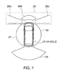
- FIG. 1 shows image-areas obtained by an exemplary around-vehicle visual recognition apparatus.
- FIG. 1 shows a vehicle 25 including the around-vehicle visual recognition apparatus 10.
- the vehicle 25 may be, for example, an automobile, truck, bus, or two-wheeled vehicle that can travel roads.
- vehicle 25 is described as an automobile.
- FIG. 2 shows the configuration of an exemplary around-vehicle visual recognition apparatus.
- FIG. 2 shows a navigation unit 11 mounted on a vehicle, that may include, for example, a controller such as a type of computer with a calculation unit such as a CPU and/or a MPU; a recording unit such as, for example, a semiconductor memory, a magnetic disk, a magnetic tape, a magnetic drum, a flash memory, a CD-ROM, a CD-R/W, a MD, a DVD-RAM, a DVD-R/W, an optical disk, a MO, an IC card, an optical card and/or a memory card; and/or a communication unit.
- a controller such as a type of computer with a calculation unit such as a CPU and/or a MPU
- a recording unit such as, for example, a semiconductor memory, a magnetic disk, a magnetic tape, a magnetic drum, a flash memory, a CD-ROM, a CD-R/W, a MD
- the navigation unit 11 may also include a an input unit for inputting information via, for example, operation keys, push buttons, a jog dial, a cross key, a remote controller and/or a touch panel.
- the navigation unit may include or be connected to a display unit 17 such as, for example, a CRT, a liquid crystal display, an LED (Light Emitting Diode) display and/or a holographic unit.
- the navigation unit 11 may include voice input unit such as, for example, a microphone and/or a voice output unit 18 such as, for example, a loud speaker and/or a headphone.
- the display unit 17 may be a touch panel with the function of input as well.
- FIG. 2 shows a camera controller 21 mounted on the vehicle.
- the camera controller may include, for example, a type of computer with a calculation unit such as a CPU and/or a MPU, and a recording unit such as a semiconductor memory, a magnetic disk, a magnetic tape, a magnetic drum, a flash memory, a CD-ROM, a CD-R/W, a MD, a DVD-RAM, a DVD-R/W, an optical disk, a MO, an IC card, an optical card and/or a memory card.
- the navigation unit 11 and the camera controller 21 may be connected for intercommunication.
- the camera controller 21 may be provided separately or included in the navigation unit 11.
- the vehicle 25 may mount, for example, a front-side camera 22, a side camera 23, and/or a backside camera 24. These cameras 22, 23, 24, may be controlled by the camera controller 21.
- the front-side camera 22, the side camera 23, and the backside camera 24 may be provided with image pickup units such a CCD (Charge Coupled Device) and/or a CMOS (Complementary Metal Oxide Semiconductor) and may be installed on a front-side, a flank and a backside of the vehicle.
- the cameras 22, 23, 24 may be configured to take images around the vehicle 25 transmit the images to the camera controller 21. As shown in FIG.
- the front-side camera 22 may take a front-side image-area 26
- the side camera 23 may take a left-side image-area 27 and a right-side image-area 28
- the backside camera 24 may take a backside image-area 29.
- the front-side image-area 26 may include a front image-area 26a, a front edge left-side image-area 26b, and a front edge right-side image-area 26c. Note that the exact placement and areas of the front-side image-area 26, of the left-side image-area 27, of the right-side image-area 28, and of the backside image-area 29 shown in FIG. 1 are exemplary; thus, they may be varied accordingly.
- each of the front-side camera 22, of the side camera 23, and of the backside camera 24 may be more than one of each of the front-side camera 22, of the side camera 23, and of the backside camera 24.
- the front-side camera 22, shown in FIG. 2 may be 3 cameras for taking respectively the front image-area 26a, the front edge left-side image-area 26b, and the front edge right-side image-area 26c.
- the front-side camera 22 may be a camera with an optical system such as, for example, a fisheye lens, a PRISM, and/or one or more optical fibers, which take the front image-area 26a, the front edge left-side image-area 26b, and the front edge right-side image-area 26c.
- the side camera 23 may be 2 cameras that respectively take the left-side image-area 27 and the right-side image-area 28, or may be more than 2 cameras that respectively take the left-side image-area 27 and the right-side image-area 28.
- the backside camera 24 may be 2 or more cameras for taking the backside image-area 29.
- the front-side camera 22, the side camera 23, and the backside camera 24 may also be a camera or cameras with a changeable focus mechanism able to change image modes from close-up to telephoto. In other words, the camera(s) may be able to zoom. Also the front-side camera 22, the side camera 23, and the backside camera 24 may be installed in order to move the image-area from side to side and/or up and down. That is the camera(s) may tilt and/or pan.
- the camera controller 21 may control these actions of the front-side camera 22, of the side camera 23, and of the backside camera 24, such as zooming, tilting, and panning.
- a position-detecting unit 12 may be connected to the navigation unit 12.
- the position-detecting unit 12 may detects, for example, a vehicle current location, a vehicle speed, a vehicle acceleration, and/or vehicle direction using a variety of sensors, such as , for example, a GPS (Global Positioning System) sensor for detecting a current position on the Earth by receiving electronic wave transmitted from a GPS satellite; a magnetic sensor for detecting earth magnetism; a distance sensor for computing vehicle driving distance; a gyro sensor for computing vehicle orientation; a beacon sensor for detecting a current position by receiving position information from beacons installed along on roads; an accelerator pedal position sensor for detecting an accelerator pedal position; a brake sensor for detecting a movement of a brake pedal operated by a driver; a turn signal sensor for detecting a movement of a turn signal lever operated by a driver; a shift lever sensor for detecting a movement of a shift lever of a transmission operated by a driver; an altimeter; a vehicle speed sensor for detecting the speed of a
- the navigation unit 11 may perform navigation processing based on, for example, one or more of the vehicle current location, vehicle speed, vehicle accelerated velocity, and/or vehicle orientation detected by the position-detecting unit 12. Note that the position-detecting unit 12 may be connected to or included in the navigation unit 11.
- a map information database 13 may be connected to or included in the navigation unit 11.
- the map information database 13 may store map information necessary to search for facilities, geographic points, and/or routes.
- the map information database 13 may include a road data file.
- the road data file may store, for example, data on all roads in Japan, including narrow streets.
- the road data file may also include, for example, intersection data, node data, road data, traffic regulation data and route display data.
- the intersection data may include data on each of intersections, such as, intersection identification numbers, roads connecting to appropriate intersections with the respective roads' number.
- the intersection data may include data for distinguishing intersection types, specifically, for example, distinguishing between intersections with traffic signals and intersections without traffic signals.
- each road may consist of a plurality of componential units called links.
- Each link may be separated and defined by, for example, an intersection, an intersection having more than three roads, a curve, and/or a point at which the road type changes.
- node refers to a point connecting two or more links.
- a node may be, for example, an intersection, an intersection having more than three roads, a point along a curve, and/or a point at which a road type changes.
- the node data may indicate at least locations and road forms stored in a map data file and consist of data on actual road forks (including such as intersections and/or T-junctions), nodes, and links connecting between each node.
- the road data may include data on each road with its respective identification number.
- the road data may include road types, a length of each road, and/or a time necessary to travel each road.
- the road types may include, for example, government road attributes such as a national road, a prefectural road, a principle regional road, and/or a highway.
- the road data may include, for each road, a width, a slope, a cant, an altitude, a bank, a road surface condition, presence or absence of dividing strips, location and/or number of traffic lanes, reduction points of traffic lanes, and/or road-narrowing points.
- each set of lanes in opposite directions may be stored as an individual road, and/or treated as a double road.
- main roads with 4 or more lanes they may be considered as double roads, and the set of inbound lanes and the set of outbound lanes may be respectively stored as independent roads in the road data.
- the road data may include, for example, curvature radius, an intersection, a T-junction, and/ or a corner entrance.
- the road data may include road attributes such as, for example, the existence and attributes of a railroad crossing, a highway entrance/exit ramp, a highway tollgate, a descending road, and/or an ascending road.
- the map data may include map data for drawing a map, based on or including such data as a node, a link, coordinates, and/or a facility location.
- the map information database 13 may include, for example, map data for storing map drawing data and/or a POI (Point Of Interest) data file.
- the map drawing data may include data, such as a node, a link, coordinates and/or a facility.
- the POI data file stores such as facility data, Town Page (R) data, and/or event data for searching for points such as a starting point, a destination, a waypoint.
- the map information database 13 3 may be connected to or included in the navigation unit 11.
- a sensor signal acquisition unit 14 may be connected to the navigation unit 11.
- the sensor signal acquisition unit 14 may be, for example, a type of computer with a calculation unit such as a CPU and/or a MPU and/or a recording unit such as a semiconductor memory and/or a magnetic disk.
- the sensor signal acquisition unit 14 may be attached to or included in the navigation unit 11.
- Corner sensors 15, for example, installed at each of 4 corners of a vehicle 25 and a steering sensor 16 for computing a steering angle may be connected to the sensor signal acquisition unit 14.
- the corner sensor 15 may be, for example, a sensor for measuring distance, such as an ultrasonic sensor, a laser radar, and/or a millimeter wave radar.
- the corner sensor 15 may detect whether a corner of a vehicle 25 reaches a set distance from an obstacle.
- the corner sensor(s) 15 maybe installed at only some of the corners of the vehicle 25. Furthermore, the set distance can be changed as necessary.
- the sensor signal acquisition unit 14 may process, for example, a sensor signal from the corner sensor 1 and/or the steering sensor 16 and may transmit the processed signal to the navigation unit 11.
- the around-vehicle visual recognition apparatus 10 may be physically, functionally, and or conceptually divided into a vehicle circumstances acquisition unit for determining the current circumstances of a vehicle 25, and an image-acquiring unit for taking images around the vehicle 25.
- the vehicle circumstances acquisition unit may include, for example, the navigation unit 11, the position-detecting unit 12, the map information database 13, the sensor signal acquisition unit 14, one or more corner sensors 15, and/or a steering sensor 16.
- the image pickup unit may include, for example, the camera controller 21, the front-side camera(s) 22, the side camera(s) 23, and/or the backside camera(s) 24.
- the around-vehicle visual recognition apparatus 10 maybe connected to or include a display unit 17 that displays, for example, in shifts, a plurality of images from around the vehicle 25 depending upon the circumstances of the vehicle 25 as determined by, for example, the vehicle circumstances acquisition unit.
- FIG. 3 shows an exemplary around-vehicle visual recognition method.
- the exemplary method may be implemented, for example, by one or more components of the above-described around-vehicle visual recognition apparatus.
- the exemplary structure of the above-described around-vehicle visual recognition apparatus may be referenced in the description, it should be appreciated that the referenced structure is exemplary, and the exemplary method need not be limited by any of the above-described exemplary structure.
- an around-vehicle visual recognition apparatus 10 acquires a driver's vehicle location is acquired (Step S1), for example, by the around-vehicle visual recognition apparatus 10.
- the position-detecting unit 12 may acquire as the driver's vehicle location, a current location of the vehicle 25.
- navigation map data is read out (Step S2), for example, the around-vehicle visual recognition apparatus 10 may read map data out of the navigation map database.
- map information may be read from map information database 13, based on the driver's vehicle location.
- the map information may include, for example, road data related to the driver's vehicle location road and/or facility data.
- a parking lot process may be performed, for example, by the exemplary method of FIG. 5.
- data on relatively large facility such as, for example, a shopping center, a theme park, and/or a golf course may be stored in the map information database 13 and that data may be accessed.
- the parking lot process may be performed.
- Step S5 Yes
- Step S6 The general road process may be performed, for example, by the exemplary method of FIG. 7.
- Highways may include, for example, not only intercity highways such as a Tomei Highway and/or a Meishin Highway, but also city highways used in regions such as, Hanshin, Nagoya and/or Fukuoka/Kitakyusyu.
- Step S8 a highway process is performed (Step S8).
- the highway process may be performed, for example, by the exemplary method of FIG. 9.
- Step S9 Yes
- Step S10 a narrow street process is performed (Step S10).
- FIG. 4 shows an exemplary display that may be used during parking lot processing.
- FIG. 5 shows an exemplary method of providing parking information that may be used during parking lot processing.
- the exemplary method may be implemented, for example, by one or more components of the above-described around-vehicle visual recognition apparatus 10.
- the exemplary structure of the above-described around-vehicle visual recognition apparatus 10 may be referenced in the description, it should be appreciated that the referenced structure is exemplary, and the exemplary method need not be limited by any of the above-described exemplary structure.
- screen representations (a-1) and (b-1) in FIG. 4 represent the display contents of a divided screen
- screens (a-2) and (b-2) in FIG. 4 show screen-display examples.
- Step S401 it is determined whether a parking operation has started (Step S401), for example, by the around-vehicle visual recognition apparatus 10.
- a parking indication may be, for example, a driver's shift change to a reverse gear, the lighting of a reverse light, and/or a driver's activation of a parking indication operation switch.
- Step S402 backside images are displayed (Step S402).
- the around-vehicle visual recognition apparatus 10 may make the display unit 17 display, as images of a backside of the vehicle 25, images of the backside camera(s) 24 and as images of sides of the vehicle 25, images of the side camera(s) 23.
- a screen 31 such as shown in (a-2) in FIG. 4 may be displayed on the display unit 17.
- the screen 31 as shown in (a-1) in FIG.
- 4 may be divided into 4 screens: a backside camera screen 31a displaying images of a backside camera; a left side camera screen 31b displaying images of a left side camera; a right side camera screen 31c displaying images of a right side camera; and a corner sensor icon screen 31d displaying a corner sensor icon.
- the around-vehicle visual recognition apparatus 10 may assume that parking is being performed regardless of a vehicle orientation. Accordingly, the screen 31 may remain on a display until the driver's vehicle location goes out of a parking lot. In other words, while the driver's vehicle location is on the parking lot, for example, even if the reverse gear changes to another position, the screen 31 keeps on display such as shown in (a-2) in FIG. 4.
- the front of the vehicle 25 may be shown so as to be oriented downward in FIG. 4., however, the backside camera screen 31a, the left side camera screen 31 b, the right side camera screen 31 c, and the corner sensor icon screen 31 d may change their direction to display, by performing vertical inversions in accordance with a traveling direction of the vehicle 25.
- a steering angle is computed and read out (Step S403).
- the steering angle may be computed by the steering sensor 16, and read out by the around-vehicle visual recognition apparatus 10.
- auxiliary lines may be drawn (Step S404) such as, for example, the anticipated whole track line 32 and the anticipated side track line 33 shown in (a-2) in FIG. 4.
- the anticipated whole track line 32 may indicate an anticipated track of the back of the vehicle 25.
- the anticipated side track line 33 may indicate the anticipated track of the front-side edge of the vehicle 25, that is, the front corner of the vehicle 25.
- the side anticipated track line 33 may be drawn corresponding to a turning inside image in either or both of the images of left and right side cameras, and it may indicate an anticipated track of a backside edge (e.g., back corner or wheel) of the vehicle when turning.
- the side anticipated track line 33 may be drawn in a corresponding to a turning outside image in either or both of the images of left and right side cameras, and it may indicate an anticipated track of a front corner of the vehicle when turning.
- the around-vehicle visual recognition apparatus 10 may display images of a side camera (Step S407), and may not perform such operations from displaying of images of the side camera and of the backside camera to drawing auxiliary lines.
- a inside color of the frame 35 can be different from other parts of the screen, an image within the frame 35 could be blinked, only the image within the frame 35 can be amplified, an image of a corner sensor icon 34 can be displayed, and/or an warning beep can be set off from the voice output unit 18. Operation of the exemplary method ends.
- FIG. 6 shows an exemplary display that may be displayed during general road processing.
- FIG. 7 shows an exemplary method of providing general road information that may be used during general road processing.
- the exemplary method may be implemented, for example, by one or more components of the above-described around-vehicle visual recognition apparatus 10.
- the exemplary structure of the above-described around-vehicle visual recognition apparatus 10 may be referenced in the description, it should be appreciated that the referenced structure is exemplary, and the exemplary method need not be limited by any of the above-described exemplary structure.
- screen representations (a-1), (b-1) and (c-1) in FIG. 6 show display contents of a divided screen, and screens (a-2), (b-2) and (c-2) in FIG. 6 show screen-display examples.
- Step S601 it is determined whether the vehicle is traveling at a high speed. For example, it may be determined whether a speed computed by the position-detecting unit 12 is a higher speed than a predetermined speed for a general road, for example, about 20 km/hour.
- Step S602 Yes
- the vehicle 25 may be considered traveling along a road and images of a backside camera may be displayed (Step S602).
- the around-vehicle visual recognition apparatus 10 may cause the display unit 17 to display images taken by backside camera 24, in preparation for lane changes.
- a screen 41 as shown in screen (a-2) in FIG. 6 may be displayed on the display unit 17.
- the screen 41 as represented in screen representation (a-1) may be divided into 2 screens: a backside camera screen 41a on which images of the backside camera may be displayed and a navigation screen on which navigation images by the navigation unit 11 may be displayed.
- a driver's vehicle position mark 43 indicating a driver's vehicle position and road lines 44 showing roads may be displayed.
- auxiliary lines may be drawn in the images of the backside camera, for backward monitoring on a general road (Step S603).
- auxiliary lines 42 for the general road may be drawn on the display unit 17 by the around-vehicle visual recognition apparatus 10.
- the auxiliary lines for backward monitoring 42 may be extension lines of a vehicle 25, that is, lines extending backward from both sides of the vehicle 25 with, for example, distance marks 42a as measures.
- the distance marks 42a may be used as distance measures from the back of the vehicle 25.
- the auxiliary lines 42 may be drawn on both sidelines of a lane. Thus, when the vehicle 25 travels on one of two lanes for each direction, its vehicle position is detected and distance marks 42a may be drawn only on the one side.
- An interval between the distance marks 42a may be, for example, about the length of an ordinary automobile, about 5m. Accordingly, a driver may estimate a distance between his/her vehicle and a following vehicle.
- a driver can set the interval between the distance marks 42a separately for each type of roads such as a general road and/or a highway, and/or depending on travel speed. For example, for a general road, the interval may be about 10 m. For the highway, the interval may be about 30 m. When set based on speed, for lower than 60 km/h travel speed, the interval may be about 10 m. For higher than about 60 km/h travel speed, the interval may be about 30 m.
- the auxiliary lines for backward monitoring 42 and the distance marks 42a can be set to display, for example, only when other vehicles are recognized in the images of the backside camera.
- the around-vehicle visual recognition apparatus 10 may cause the display unit 17 to display images of the side camera(s) 23 on the side of the operating direction indicator, that is, on a turning direction side (Step S605).
- a screen showing images of the side camera taken by the side camera 23, along with a backside camera screen 41a may be shown on display unit 17. Based on the images, a driver can visually recognize other vehicles that intend to pass his/her vehicle from behind.
- Step S604 No
- a steering angle computed by the steering sensor 16 may be used to determine whether a lane change is occurring.
- Step S606 Yes
- the around-vehicle visual recognition apparatus 10 may shift to images of the side camera of the turning direction side.
- images of the side camera of the turning direction side may be displayed on the display unit 17.
- Step S606 No
- the screen 41 as shown in screen representation (b-1) in FIG. 6 may be divided into 3 screens: a side camera screen 41 c on which images of the side camera are displayed, an icon corner sensor screen 41d on which a corner sensor icon is displayed, and a navigation screen 41b on which navigation images by the navigation unit 11 are displayed.
- Step S610 the a steering angle, for example, computed by the steering sensor 16, is read out (Step S610) and auxiliary lines are drawn on the basis of the read steering angle (Step S611) such as, for example, an anticipated side track line 45 shown in (b-2) in FIG. 6. Note that in screen (b-2) in FIG. 6, since the vehicle 25 goes ahead, the anticipated side track line 45 indicates an anticipated track of a left back corner or a left back wheel of the vehicle 25 on the turning inside.
- an inside color of the frame 46 may be different from other parts, a inside image of the frame 46 may be blinked, only the inside image of the frame 46 may be amplified, a corner sensor icon image may be displayed, and/or an warning beep may be set off from the voice output unit 18.
- FIG. 8 shows an exemplary display that may be displayed during highway processing.
- FIG. 9 shows an exemplary method of providing highway information that may be used during highway processing.
- the exemplary method may be implemented, for example, by one or more components of the above-described around-vehicle visual recognition apparatus 10.
- the exemplary structure of the above-described around-vehicle visual recognition apparatus 10 may be referenced in the description, it should be appreciated that the referenced structure is exemplary, and the exemplary method need not be limited by any of the above-described exemplary structure.
- screen representations (a-1) and (b-1) in FIG. 8 show display contents of a divided screen
- screens (a-2) and (b-2) in FIG. 8 show screen-display
- Step S801 it is determined whether the vehicle is traveling at a high speed. For example, it may be determined whether a speed computed by the position-detecting unit 12 is higher than a predetermined speed for a highway, for example, about 60 km/hour.
- Step S801 Yes
- the vehicle 25 can be considered traveling at a high speed, and thus not being involved in a traffic jam.
- backside images are displayed (Step S802).
- the around-vehicle visual recognition apparatus 10 may cause the display unit 17 to display images taken by the backside camera 24, in preparation for lane changes.
- a screen 51 as shown in screen (a-2) in FIG. 8 may be displayed on the display unit 17.
- the screen 51 as shown in representation (a-1) in FIG. 8 may divided into 2 screens: a backside camera screen 41a on which images of the backside camera may be displayed and a navigation screen on which navigation images by the navigation unit 11 may be displayed.
- a driver's vehicle position mark 53 indicating a driver's vehicle position and road lines 54 showing roads may be displayed.
- the around-vehicle visual recognition unit 10 may draw in the images of the backside camera, auxiliary lines for backward monitoring 52 on the highway.
- the auxiliary lines for backward monitoring 52 may be rearward extension lines of the vehicle 25 with distance marks 52a as a measure.
- the distance marks 52a may be used as a distance measure from the back of the vehicle 25.
- An interval between the distance marks 52a may be longer than those used on the general road, for example, same as an interval of following distance confirmation sign boards, about 50m.
- the driver can figure out a distance between his/her vehicle and a following vehicle.
- the driver can also set the interval between the distance-measuring auxiliary lines 52a for each type of roads such as the general road and/or the highway, or for each travel speed.
- the auxiliary lines for backward monitoring 52 and the distance-measuring auxiliary lines 52a can be set to display only when other vehicles are recognized in the images of the backside camera.
- a side-camera screen 51c showing the images of, for example, the side camera 23, along with a backside camera screen 5 1 a are displayed on the display unit 17.
- the screen 51 as shown in representation (b-1) in FIG. 8 is divided into 2 screens: the backside camera screen 51 a on which images of the backside camera are displayed and the side camera screen 5 l c on which images of the side camera are displayed. Based on the images, the driver can visually recognize other vehicles that intend to pass his/her vehicle from behind.
- Step S804 it is determined whether the direction indicator of the vehicle 25 is operating. In other words, in a traffic jam, an operation of the direction indicator triggers displaying of the images of the side camera.
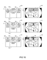
- FIG. 10 shows an exemplary display that may be displayed during a narrow street processing.
- FIG. 11 shows an exemplary method of providing narrow road information.
- the exemplary method may be implemented, for example, by one or more components of the above-described around-vehicle visual recognition apparatus 10.
- the exemplary structure of the above-described around-vehicle visual recognition apparatus 10 may be referenced in the description, it should be appreciated that the referenced structure is exemplary, and the exemplary method need not be limited by any of the above-described exemplary structure.
- screen representations (a-1), (b-1) and (c-1) in FIG. 10 show display contents of a divided screen
- screens (a-2), (b-2) and (c-2) in FIG. 11 show screen-display examples.
- Step S1001 it is determined whether the vehicle is traveling at a low speed. For example, it may be determined whether the speed computed by the position-detecting unit 12 is lower than a predetermined speed for the narrow street, for example, about 10 km/hour.
- Step S1002 Yes
- the around-vehicle visual recognition unit 10 may cause the display unit 17 display images taken by the side camera(s) 23.
- a screen 61 as shown in screen (a-2) in FIG.10 may be displayed on the display unit 17. Note that the screen 61 as shown in representation (a-1) in FIG.
- a navigation screen 61a on which navigation images by the navigation unit 11 may be displayed
- a left-side camera screen 61b on which images of the left-side camera may be displayed
- a right-side camera screen 61c on which images of the right-side camera may be displayed
- a corner sensor icon screen 61d on which the corner sensor icon may be displayed.
- the front of the vehicle 25 is oriented upward.
- a vehicle position mark 63 indicating a driver's vehicle position and road lines 64 showing roads may be shown.
- a steering angle is computed, for example, by the steering sensor 16, and read out (Step S1003) and an auxiliary line, such as an anticipated side track line 64 shown in screen (a-2) in FIG. 10, is drawn (Step S1004) on the basis of the read steering angle.
- screen (a-2) in FIG. 10 shows a case of the vehicle 25 turning to the left at an intersection
- the anticipated side track line 64 indicates an anticipated track of a left back corner or a left back wheel of the vehicle 25, on a turning inside.
- Step S 1005 No
- Step S1001 No
- an inside color of the frame 65 may be different from other parts, an inside image of the frame 65 may be blinked, only an inside image of the frame 46 may be amplified, a corner sensor icon could be displayed, and/or an warning beep could be set off from the voice output unit 18.
- the around-vehicle visual recognition unit 10 may makes the display unit 17 shift between a plurality of images of the area around a vehicle area, for example, in accordance with the vehicle's circumstances. Accordingly, a driver may obtain accurate information about the area around the vehicle by visually recognizing the images on the display unit 17. Thus, the driver may easily and safely drive a vehicle without worry.
- the around-vehicle visual recognition apparatus 10 may cause the display unit 17 to shift the display of the plurality of images based on a current location of the vehicle 25.
- the current location of the vehicle 25 may, for example, identify types of places of the current location of the vehicle 25, for example, a parking lot and/or a road, or identify road attributes.
- images of a backside camera(s) 24, images of a side camera(s) 23, and images of a front-side camera(s) 22 may be displayed in shifts on the display unit 17, in accordance with the location of the vehicle. Therefore, a driver can visually recognize images of an area(s) around the vehicle that is most useful to the driver depending on the circumstances of the vehicle 25.
- the around-vehicle visual recognition apparatus 10 may makes the display unit 17 shift the images displayed in accordance with driving situations, such as, a travel speed or a driving direction.
- driving situations such as, a travel speed or a driving direction.
- the displays may be as follows: if on a general road and/or a highway and/or the travel speed is higher than a predetermined speed, the images of the backside camera are displayed in shifts on the display unit 17; if on a narrow street and/or the travel speed is lower than a predetermined speed, the images of the side camera are displayed in shifts on the display unit 17. Therefore, the driver can visually recognize images of the areas around the vehicle most useful to the driver.
- the around-vehicle visual recognition apparatus 10 makes the display unit 17 shift the images displayed in accordance with driving situations, such as the driving direction.
- the driving direction may include going straight ahead, reversing, or turning right or left. For example, if on a general road and/or a highway and/or the travel speed is higher than a predetermined speed, when the driving direction is going straight ahead, the images of the backside camera are displayed in shifts on the display unit 17.
- the driving direction is one of the turning directions
- the images of the side camera are displayed in shifts on the display unit 17.
- the images of the front-side camera are displayed in shifts on the display unit 17. Therefore, a driver can visually recognize images of an area or areas most useful based on the driving situations of the vehicle 25.
- the around-vehicle visual recognition apparatus 10 when the around-vehicle visual recognition apparatus 10 determines that the vehicle 25 is parking on the basis of circumstances of the vehicle 25, it may cause the display unit 17 to display the images of the backward and the sides of the vehicle 25, an anticipated track of the back of the vehicle 25 in the images of the backward, and/or an anticipated track of the front-side edge of the vehicle 25 in the images of sides. For example, if the driver's vehicle location not on a road, the around-vehicle visual recognition apparatus 10 may determine that the vehicle is parking and may cause the display unit 17 display the backside camera screen 31 a, the left side camera screen 31b, and the right side camera screen 31c.
- An anticipated whole track line 32 may be displayed on the backside camera screen 31 a, and an anticipated side track line 33 may be displayed on the left side camera screen 31b or the right side camera screen 31c.
- the anticipated whole track line 32 and the anticipated side track line 33 may be drawn on the basis of a steering angle read by the steering sensor 16. Therefore, when parking the vehicle, the driver can visually recognize the area behind the vehicle 25 and can accurately understand the anticipated track of the back of the vehicle 25 thereby easily and safely driving the vehicle. Further, the driver can visually recognize obstacles on the sides of the vehicle by visually recognizing images of the sides of the vehicle 25. Therefore, when turning by backing the vehicle 25, the driver can accurately understand the anticipated track of the front-side edge passing the extreme outside and can avoid contacts against the obstacles on the sides.
- the around-vehicle visual recognition apparatus 10 may determines that the vehicle 25 is traveling on a road, for example, on the basis of conditions of the vehicle 25. When traveling at a high speed, the around-vehicle visual recognition apparatus 10 may cause the display unit 17 to display images of behind of the vehicle 25 including extension lines of the vehicle 25 having a. When traveling at a low speed, the around-vehicle visual recognition apparatus 10 may make the display unit 17 display images of the turning direction side of the vehicle 25, when the vehicle 25 is making a turn.
- the around-vehicle visual recognition apparatus 10 may cause the display unit 17 to display a backside camera screen 41a or 51a.
- auxiliary lines for backward monitoring 42 or 52 with distance-measuring auxiliary lines 42a or 52a may be drawn.
- the driver can figure out a distance between his/her vehicle and a following vehicle.
- the around-vehicle visual recognition apparatus 10 may cause the display unit 17 to display images of the turning direction side of the vehicle 25. As a result, the driver can visually recognize other vehicles that may intend to pass his/her vehicle from behind.
- the around-vehicle visual recognition apparatus 10 may cause the display unit 17 to display a side camera screen 41c or 51c. Therefore, the driver can visually recognize obstacles and other vehicles on the sides. Further, when the vehicle 25 is traveling at a low speed on a general road and is making a turn thereon, an anticipated side track line 45 as an anticipated track of the backside edge of the vehicle 25 may be drawn on the side camera screen 41 c. Therefore, the driver can accurately understand the anticipated track of the backside edge passing the extreme inside and can avoid contacts against the obstacles on the sides.
- FIGS. 12A-12C show image-areas of an exemplary around-vehicle visual recognition apparatus 110 when mounted on a vehicle 116.
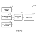
- FIG. 13 is a block diagram showing the exemplary around-vehicle visual recognition apparatus 110.
- elements and advantages of the around-vehicle visual recognition apparatus 110 that are similar to the previously described around-vehicle visual recognition apparatus 10 may be omitted from the following description.
- the around-vehicle visual recognition apparatus 110 may include a navigation unit 111, for example, similar to the navigation unit 11, previously described.
- the navigation unit 111 may include a camera controller for controlling a backside camera 112.
- the camera controller may be separate from and attached to the navigation unit 111 or include in the navigation unit 111.
- a vehicle 116 may mounts the backside camera 112.
- the backside camera 112 may be provided with, for example, an image pickup unit such as CCD (Charge Coupled Device) and/or CMOS (Complementary Metal Oxide Semiconductor) and an optical system such as, for example, a lens or PRISM.
- the backside camera 112 may be set on a back of the vehicle, may take images of the backside area of the vehicle 116 and may transmit the images to the navigation unit 111.
- the backside camera 112 may be two or more cameras.
- the backside camera 112 may include a changeable image-area unit that permits the camera 112 to change image areas.
- the changeable image-area unit may include, for example, a changeable focus mechanism such as zoom lens that changes the focus distance of optical system. Accordingly the camera 112 can change image modes from wide angle to telephoto, in other words, zoom.
- the changeable image-area unit may be one that changes an image area by using a wide-angle lens and/or a fisheye lens for the primary lens or in addition to a primary lens.
- the changeable image-area unit may move the image area, for example, side to side and/or up and down, in other words, the changeable image-area unit may allow tilt and/or pan, for example, by moving the entire backside camera 112 and/or a part of the camera 112, such as moving or rotating the optical axis of the optical lens from side to side and up and down.
- the backside camera 112 may be controlled by, for example, the navigation unit 111.
- the image-area of the backside camera 112 may be changeable.
- An image-area A of the backside camera 112 is an exemplary default or standard setting condition and an image-area B of the backside camera 112 is a maximum image-area setting.
- FIG. 12A illustrates the up and down rotation of the backside camera 112 on its optical axis by tilting and shows, by arrow C, the possible changes of the image-area of the backside camera 112 within the maximum image-area.
- FIG. 12B illustrates the variable image area of the backside camera 112. That is, the maximum image-area B may be increased by using a wide image-area lens such as wide-angle lens and/or fisheye lens.
- FIG. 12C illustrates how the optical system of the backside camera 112 may be changed from wide-angle lens to telescope lens, for example, by zooming. That is, it is possible to change the image-area of the backside camera 112 within the maximum image-area B, as shown with arrows D, by changing the focus distance of the optical system as shown with arrow E. It should be appreciated that it is possible to change the image-area of the backside camera 112 in a number of ways by conveniently combining the above operations: tilting, using wide image-area lens, and/or zooming.
- the navigation unit 111 may include or be connected to a position-detecting unit 113, similar to position detection unit 12.
- the position-detecting unit 113 may detect, for example, a current location, a vehicle travel speed, a vehicle accelerated velocity, vehicle orientation using a variety of sensors.
- the navigation unit 111 may also include a map information database 114, similar to map information database 13 for storing map information necessary to search for facilities, geographic points, and/or routes.
- the navigation unit 111 may change the image-area of the backside camera 112 in accordance with the circumstances of the vehicle, as well as in accordance with ordinary navigation functions such as detecting facilities and/or geographical points. For example, in accordance with the current vehicle location of the vehicle 116, a travel speed, and/or a driving direction, the navigation unit 111 may cause the image-area of the backside camera 112 to be changed The images may be displayed on the display unit 115.
- the image area when the vehicle 116 is traveling on a highway, the image area may be set as about 50 to 200 meters behind the vehicle 116. When the vehicle 116 is traveling on a general road, the image area may be set at about 5 to 50 meters behind the vehicle 16. When the vehicle 116 is traveling on a narrow street, the image area may be set at about 0 to 5 meters behind the vehicle 116. In addition, when, for example, the vehicle 116 is traveling on a general road, the higher the travel speed gets, the image area may become farther from the vehicle 116 and/or utilize a wider angle. Note that according to this example, the backside camera images taken by the backside camera 112 may be continuously displayed irrespective of the vehicle circumstances. If the driver determines that the display of the images from camera 112 is unnecessary, the driver can adjust the settings to not display the images of camera 112 by, for example, operating an input switch and/or by changing a setting on a setting screen.
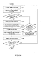
- FIG. 14 shows an exemplary around-vehicle visual recognition method.
- the exemplary method may be implemented, for example, by one or more components of the above-described around-vehicle visual recognition apparatus 110.
- the exemplary structure of the above-described around-vehicle visual recognition apparatus 110 may be referenced in the description, it should be appreciated that the referenced structure is exemplary, and the exemplary method need not be limited by any of the above-described exemplary structure.
- a driver's vehicle location is acquired (Step S11).
- the position-detecting unit 113 may acquire as the driver's vehicle location, a current location of the vehicle 116 detected by a variety of sensors, such as a GPS sensor, a magnetic sensor, a gyro sensor, and/or a vehicle speed sensor.
- map data is reads out (Step S12), for example, from a navigation map database, such as, map information database 114.
- the map information may include road data on the driver's vehicle location road and/or facility data.
- the image area of the backside camera 112 is set for each type of roads (Step S 15).
- the image-area may be set as about 50 to 200 meters behind the vehicle 16.
- the image-area may be set as about 5 to 50 meters behind the vehicle 116.
- the image-area may be set as about 0 to 5 meters behind the vehicle 116.
- a travel speed for example, computed by the position-detecting unit 113 is acquired (Step S16) and the image-area is fine-tuned based on the travel speed (Step S 17).
- the image area may be fine-tuned by widening or narrowing the optical axis angle of the backside camera 112 according to the image-area set for each type of roads based on the travel speed of the vehicle 116.
- the optical axis angle of the backside camera 112 may get fine-tuned wherein the higher the speed of the vehicle 116, the further the image area from the vehicle 116.
- a range of fine-tuning may be predetermined for each type of road and stored in a storage unit of the navigation unit 111.
- the around-vehicle visual recognition apparatus 110 sets image-area of the backside camera 112 for reverse parking (Step S 19).
- the image-area may be set at about 0 to 5 meters behind the vehicle 116.
- the around-vehicle visual recognition apparatus 110 may change an image-area in accordance with the vehicle's circumstances and may display backside images on the display unit 115.
- a driver may obtain accurate information about the rear of the vehicle, by visually recognizing images on the display unit 115 and can easily and safely drive the vehicle.
- the around-vehicle visual recognition apparatus 110 may change the image area based on the current locations of the vehicle 116.
- the around-vehicle visual recognition apparatus 110 may change an image distance from the vehicle back edge, for example, by rotating the backside camera 112 on its optical axis, or by changing the focus distance. Therefore, a driver can visually recognize an area of the rear of the vehicle that is highly relevant to the vehicle's situation.
- the image-area may be about 0-5 meters from the back edge of the vehicle 116, it is possible to visually recognize backside camera images of the area necessary for reverse parking of the vehicle 116.
- the image-area may be about 50-200 meters from the back edge of the vehicle 116, it is possible to visually recognize other vehicles approaching from behind at a high speed.
- the around-vehicle visual recognition apparatus 110 may change the image area based on a travel speed and/or a driving direction of the vehicle 116.
- the image-area may be changed so as to take a further-away image area from the vehicle 116 as the vehicle 116 speeds up. That is, the higher the speed, the longer the inter-vehicle distance becomes, thus, the driver can visually recognize backside camera images highly relevant to the travel speed of the vehicle 116.
- the around-vehicle visual recognition apparatus 110 may change the image area based on whether the driving direction is forward or backward.
- the around-vehicle visual recognition apparatus 110 sets image-area as about 0 to 5 meters behind the vehicle 116. Therefore, a driver can visually recognize an area of the rear of the vehicle that is highly relevant to the vehicle's situation.
Abstract
Description
- The disclosure of
Japanese Patent Application Nos. 2005-084552 2005-086211 filed on March 24, 2005 2005-086373 filed on March 24, 2005 2005-086500 filed on March 24, 2005 - Related Technical Fields include visual recognition systems, methods, and programs for vehicles.
- Conventional visual recognition apparatuses take images around a vehicle by cameras mounted on a vehicle, such as an automobile, to assist in the driving of the vehicle (see, e.g.,
Japanese Unexamined Patent Application Publication No. 2003-127772 - The above conventional visual recognition apparatuses only display images of both sides of the vehicle taken in the front part of the vehicle. Therefore, images taken in other directions or from other parts of the vehicle are not available to a driver. Specifically, images of other areas around the vehicle that are difficult for a driver to see are not available. Furthermore, such areas may vary based on the travel circumstances of the vehicle and/or the vehicle's driving situations. The above conventional visual recognition apparatuses do not change the areas which may viewed on the display unit based on changing travel circumstances of the vehicle and/or the vehicle's driving situations.
- In view of at least one or more of the above-described deficiencies in conventional systems, it is beneficial to provide a visual recognition apparatus enabling a driver to accurately view more areas around a vehicle (an "around-vehicle area") and thus to easily and safely drive a vehicle without worry. This may be done, for example, by making a display unit display a plurality of image of the around-vehicle area in accordance with the vehicle's circumstances.
- Various exemplary implementations of the principles described herein thus provide around-vehicle visual recognition apparatus, methods, and programs that may acquire circumstances of a vehicle, including the vehicle's location and may cause a camera to take images around the vehicle. The apparatus, methods, and programs may determine at least one first area around the vehicle that is more relevant to a driver based on the circumstances of the vehicle than another area around the vehicle and may display an image of the at least one first area on a display.
- Exemplary implementations will now be described with reference to the accompanying drawings, wherein:
- FIG. 1 shows areas of images obtained by an exemplary around-vehicle visual recognition apparatus;
- FIG. 2 is a block diagram showing an exemplary around-vehicle visual recognition apparatus;
- FIG. 3 shows an exemplary around-vehicle visual recognition method;
- FIG. 4 shows an exemplary screen for showing parking information;
- FIG. 5 shows an exemplary method of providing parking information;
- FIG. 6 shows an exemplary screen for showing general road information;
- FIG. 7 shows an exemplary method of providing general road information;
- FIG. 8 shows an exemplary screen for showing highway information;
- FIG. 9 shows an exemplary method of providing highway information;
- FIG. 10 shows an exemplary screen for showing narrow road information;
- FIG. 11 shows an exemplary method of providing narrow road information;
- FIGS. 12A-12C show an exemplary image area of an around-vehicle visual recognition apparatus;
- FIG. 13 is a block diagram showing an exemplary around-vehicle visual recognition apparatus; and
- FIG. 14 shows an exemplary around-vehicle visual recognition method.
- FIG. 1 shows image-areas obtained by an exemplary around-vehicle visual recognition apparatus. FIG. 1 shows a
vehicle 25 including the around-vehiclevisual recognition apparatus 10. Thevehicle 25 may be, for example, an automobile, truck, bus, or two-wheeled vehicle that can travel roads. For ease of explanation, according to this example,vehicle 25 is described as an automobile. - FIG. 2 shows the configuration of an exemplary around-vehicle visual recognition apparatus. FIG. 2 shows a
navigation unit 11 mounted on a vehicle, that may include, for example, a controller such as a type of computer with a calculation unit such as a CPU and/or a MPU; a recording unit such as, for example, a semiconductor memory, a magnetic disk, a magnetic tape, a magnetic drum, a flash memory, a CD-ROM, a CD-R/W, a MD, a DVD-RAM, a DVD-R/W, an optical disk, a MO, an IC card, an optical card and/or a memory card; and/or a communication unit. Thenavigation unit 11 may also include a an input unit for inputting information via, for example, operation keys, push buttons, a jog dial, a cross key, a remote controller and/or a touch panel. The navigation unit may include or be connected to adisplay unit 17 such as, for example, a CRT, a liquid crystal display, an LED (Light Emitting Diode) display and/or a holographic unit. Thenavigation unit 11 may include voice input unit such as, for example, a microphone and/or avoice output unit 18 such as, for example, a loud speaker and/or a headphone. Thedisplay unit 17 may be a touch panel with the function of input as well. - FIG. 2 shows a
camera controller 21 mounted on the vehicle. The camera controller may include, for example, a type of computer with a calculation unit such as a CPU and/or a MPU, and a recording unit such as a semiconductor memory, a magnetic disk, a magnetic tape, a magnetic drum, a flash memory, a CD-ROM, a CD-R/W, a MD, a DVD-RAM, a DVD-R/W, an optical disk, a MO, an IC card, an optical card and/or a memory card. Thenavigation unit 11 and thecamera controller 21 may be connected for intercommunication. Thecamera controller 21 may be provided separately or included in thenavigation unit 11. - Returning to FIG. 1, the
vehicle 25 may mount, for example, a front-side camera 22, aside camera 23, and/or abackside camera 24. Thesecameras camera controller 21. The front-side camera 22, theside camera 23, and thebackside camera 24 may be provided with image pickup units such a CCD (Charge Coupled Device) and/or a CMOS (Complementary Metal Oxide Semiconductor) and may be installed on a front-side, a flank and a backside of the vehicle. Thecameras vehicle 25 transmit the images to thecamera controller 21. As shown in FIG. 1, the front-side camera 22 may take a front-side image-area 26, theside camera 23 may take a left-side image-area 27 and a right-side image-area 28, and thebackside camera 24 may take a backside image-area 29. The front-side image-area 26 may include a front image-area 26a, a front edge left-side image-area 26b, and a front edge right-side image-area 26c. Note that the exact placement and areas of the front-side image-area 26, of the left-side image-area 27, of the right-side image-area 28, and of the backside image-area 29 shown in FIG. 1 are exemplary; thus, they may be varied accordingly. - Furthermore there may be more than one of each of the front-
side camera 22, of theside camera 23, and of thebackside camera 24. For example, the front-side camera 22, shown in FIG. 2, may be 3 cameras for taking respectively the front image-area 26a, the front edge left-side image-area 26b, and the front edge right-side image-area 26c. Alternatively, the front-side camera 22 may be a camera with an optical system such as, for example, a fisheye lens, a PRISM, and/or one or more optical fibers, which take the front image-area 26a, the front edge left-side image-area 26b, and the front edge right-side image-area 26c. Similarly, theside camera 23 may be 2 cameras that respectively take the left-side image-area 27 and the right-side image-area 28, or may be more than 2 cameras that respectively take the left-side image-area 27 and the right-side image-area 28. Thebackside camera 24 may be 2 or more cameras for taking the backside image-area 29. - The front-
side camera 22, theside camera 23, and thebackside camera 24 may also be a camera or cameras with a changeable focus mechanism able to change image modes from close-up to telephoto. In other words, the camera(s) may be able to zoom. Also the front-side camera 22, theside camera 23, and thebackside camera 24 may be installed in order to move the image-area from side to side and/or up and down. That is the camera(s) may tilt and/or pan. Thecamera controller 21 may control these actions of the front-side camera 22, of theside camera 23, and of thebackside camera 24, such as zooming, tilting, and panning. - A position-detecting
unit 12 may be connected to thenavigation unit 12. The position-detectingunit 12 may detects, for example, a vehicle current location, a vehicle speed, a vehicle acceleration, and/or vehicle direction using a variety of sensors, such as , for example, a GPS (Global Positioning System) sensor for detecting a current position on the Earth by receiving electronic wave transmitted from a GPS satellite; a magnetic sensor for detecting earth magnetism; a distance sensor for computing vehicle driving distance; a gyro sensor for computing vehicle orientation; a beacon sensor for detecting a current position by receiving position information from beacons installed along on roads; an accelerator pedal position sensor for detecting an accelerator pedal position; a brake sensor for detecting a movement of a brake pedal operated by a driver; a turn signal sensor for detecting a movement of a turn signal lever operated by a driver; a shift lever sensor for detecting a movement of a shift lever of a transmission operated by a driver; an altimeter; a vehicle speed sensor for detecting the speed of a vehicle. Thenavigation unit 11 may perform navigation processing based on, for example, one or more of the vehicle current location, vehicle speed, vehicle accelerated velocity, and/or vehicle orientation detected by the position-detectingunit 12. Note that the position-detectingunit 12 may be connected to or included in thenavigation unit 11. - A
map information database 13 may be connected to or included in thenavigation unit 11. Themap information database 13 may store map information necessary to search for facilities, geographic points, and/or routes. Themap information database 13 may include a road data file. The road data file may store, for example, data on all roads in Japan, including narrow streets. The road data file may also include, for example, intersection data, node data, road data, traffic regulation data and route display data. The intersection data may include data on each of intersections, such as, intersection identification numbers, roads connecting to appropriate intersections with the respective roads' number. The intersection data may include data for distinguishing intersection types, specifically, for example, distinguishing between intersections with traffic signals and intersections without traffic signals. - As used herein, the term link refers to, for example, a road or portion of a road. For example, according to one type of road data, each road may consist of a plurality of componential units called links. Each link may be separated and defined by, for example, an intersection, an intersection having more than three roads, a curve, and/or a point at which the road type changes. As used herein, the term "node" refers to a point connecting two or more links. A node may be, for example, an intersection, an intersection having more than three roads, a point along a curve, and/or a point at which a road type changes. The node data may indicate at least locations and road forms stored in a map data file and consist of data on actual road forks (including such as intersections and/or T-junctions), nodes, and links connecting between each node.
- The road data may include data on each road with its respective identification number. The road data may include road types, a length of each road, and/or a time necessary to travel each road. The road types may include, for example, government road attributes such as a national road, a prefectural road, a principle regional road, and/or a highway.
- The road data may include, for each road, a width, a slope, a cant, an altitude, a bank, a road surface condition, presence or absence of dividing strips, location and/or number of traffic lanes, reduction points of traffic lanes, and/or road-narrowing points. In the case of highways and/or main roads, each set of lanes in opposite directions may be stored as an individual road, and/or treated as a double road. For example, in the case of main roads with 4 or more lanes, they may be considered as double roads, and the set of inbound lanes and the set of outbound lanes may be respectively stored as independent roads in the road data. In addition, for road corners, the road data may include, for example, curvature radius, an intersection, a T-junction, and/ or a corner entrance. The road data may include road attributes such as, for example, the existence and attributes of a railroad crossing, a highway entrance/exit ramp, a highway tollgate, a descending road, and/or an ascending road. The map data may include map data for drawing a map, based on or including such data as a node, a link, coordinates, and/or a facility location.
- The
map information database 13 may include, for example, map data for storing map drawing data and/or a POI (Point Of Interest) data file. The map drawing data may include data, such as a node, a link, coordinates and/or a facility. And the POI data file stores such as facility data, Town Page (R) data, and/or event data for searching for points such as a starting point, a destination, a waypoint. Note that themap information database 13 3 may be connected to or included in thenavigation unit 11. - A sensor
signal acquisition unit 14 may be connected to thenavigation unit 11. The sensorsignal acquisition unit 14 may be, for example, a type of computer with a calculation unit such as a CPU and/or a MPU and/or a recording unit such as a semiconductor memory and/or a magnetic disk. The sensorsignal acquisition unit 14 may be attached to or included in thenavigation unit 11.Corner sensors 15, for example, installed at each of 4 corners of avehicle 25 and asteering sensor 16 for computing a steering angle may be connected to the sensorsignal acquisition unit 14. Thecorner sensor 15 may be, for example, a sensor for measuring distance, such as an ultrasonic sensor, a laser radar, and/or a millimeter wave radar. Thecorner sensor 15 may detect whether a corner of avehicle 25 reaches a set distance from an obstacle. The corner sensor(s) 15 maybe installed at only some of the corners of thevehicle 25. Furthermore, the set distance can be changed as necessary. The sensorsignal acquisition unit 14 may process, for example, a sensor signal from thecorner sensor 1 and/or thesteering sensor 16 and may transmit the processed signal to thenavigation unit 11. - The around-vehicle
visual recognition apparatus 10, may be physically, functionally, and or conceptually divided into a vehicle circumstances acquisition unit for determining the current circumstances of avehicle 25, and an image-acquiring unit for taking images around thevehicle 25. In this case, the vehicle circumstances acquisition unit may include, for example, thenavigation unit 11, the position-detectingunit 12, themap information database 13, the sensorsignal acquisition unit 14, one ormore corner sensors 15, and/or asteering sensor 16. The image pickup unit may include, for example, thecamera controller 21, the front-side camera(s) 22, the side camera(s) 23, and/or the backside camera(s) 24. The around-vehiclevisual recognition apparatus 10 maybe connected to or include adisplay unit 17 that displays, for example, in shifts, a plurality of images from around thevehicle 25 depending upon the circumstances of thevehicle 25 as determined by, for example, the vehicle circumstances acquisition unit. - Hereinafter, operations of the around-vehicle
visual recognition apparatus 10 with the above-mentioned configuration will be described. - FIG. 3 shows an exemplary around-vehicle visual recognition method. The exemplary method may be implemented, for example, by one or more components of the above-described around-vehicle visual recognition apparatus. However, even though the exemplary structure of the above-described around-vehicle visual recognition apparatus may be referenced in the description, it should be appreciated that the referenced structure is exemplary, and the exemplary method need not be limited by any of the above-described exemplary structure.
- As shown in FIG. 3, first, an around-vehicle
visual recognition apparatus 10 acquires a driver's vehicle location is acquired (Step S1), for example, by the around-vehiclevisual recognition apparatus 10. For example, the position-detectingunit 12 may acquire as the driver's vehicle location, a current location of thevehicle 25. Next, navigation map data is read out (Step S2), for example, the around-vehiclevisual recognition apparatus 10 may read map data out of the navigation map database. Specifically, map information may be read frommap information database 13, based on the driver's vehicle location. The map information may include, for example, road data related to the driver's vehicle location road and/or facility data. - Next, it is determined whether the driver's vehicle location is not on a road (Step S3), for example, by the around-vehicle
visual recognition apparatus 10. If the driver's vehicle location is not on a road (Step S3 = Yes), it may be assumed that the driver's vehicle location is on a parking lot or a facility site. Accordingly, a parking lot process is performed (Step S4), for example, by the around-vehiclevisual recognition apparatus 10. The parking lot process may be performed, for example, by the exemplary method of FIG. 5. In this case, data on relatively large facility such as, for example, a shopping center, a theme park, and/or a golf course may be stored in themap information database 13 and that data may be accessed. Even if the driver's vehicle location is not on any of facility sites stored in themap information database 13, when the driver's vehicle location is not on a road, it is likely that the driver's vehicle is in a parking lot. Thus, in spite of the lack of facility information, when the driver's vehicle location is not on the road, the parking lot process may be performed. - If the driver's vehicle location is on the road (Step S3 = No), it is then determined whether the driver's vehicle location is on a general road or not (Step S5). A general road may be, for example, a national road, a prefectural road, a principle regional road of government road attributes, and does not include highways and/or narrow streets. When the driver's vehicle location is on the general road (Step S5 = Yes), a general road process may be performed (Step S6). The general road process may be performed, for example, by the exemplary method of FIG. 7.
- If the driver's vehicle location is not on the general road (Step S5 = No), it is determined whether the driver's vehicle location is on a highway (Step S7), for example, by the around-vehicle
visual recognition apparatus 10. Highways may include, for example, not only intercity highways such as a Tomei Highway and/or a Meishin Highway, but also city highways used in regions such as, Hanshin, Nagoya and/or Fukuoka/Kitakyusyu. When the driver's vehicle location is on the highway (Step S7 = Yes), a highway process is performed (Step S8). The highway process may be performed, for example, by the exemplary method of FIG. 9. - If the driver's vehicle location is not on the highway (Step S7 = No), it is then determined whether the driver's vehicle location is on a narrow street (Step S9). A narrow street may be, for example, a local street used for daily life and/or a street with a little traffic. A narrow street may be a street whose width is less than a predetermined value, for example, about 5.5 m. When the driver's vehicle location is on the narrow street (Step S9 = Yes), a narrow street process is performed (Step S10). The narrow street process may be performed, for example, by the exemplary method of FIG. 11. If the driver's vehicle location is not on the narrow street (Step S9 = No), operation of the exemplary method ends.
- Hereinafter, operations of the parking lot processing will be described.
- FIG. 4 shows an exemplary display that may be used during parking lot processing. FIG. 5 shows an exemplary method of providing parking information that may be used during parking lot processing. The exemplary method may be implemented, for example, by one or more components of the above-described around-vehicle
visual recognition apparatus 10. However, even though the exemplary structure of the above-described around-vehiclevisual recognition apparatus 10 may be referenced in the description, it should be appreciated that the referenced structure is exemplary, and the exemplary method need not be limited by any of the above-described exemplary structure. - Note that screen representations (a-1) and (b-1) in FIG. 4 represent the display contents of a divided screen, and screens (a-2) and (b-2) in FIG. 4 show screen-display examples.
- As shown in FIG. 5, first, it is determined whether a parking operation has started (Step S401), for example, by the around-vehicle
visual recognition apparatus 10. For example, it may be determined whether there is a parking indication operation. In this case, a parking indication may be, for example, a driver's shift change to a reverse gear, the lighting of a reverse light, and/or a driver's activation of a parking indication operation switch. - If the parking indication operation is performed (Step S401 = Yes), backside images are displayed (Step S402). For example, the around-vehicle
visual recognition apparatus 10 may make thedisplay unit 17 display, as images of a backside of thevehicle 25, images of the backside camera(s) 24 and as images of sides of thevehicle 25, images of the side camera(s) 23. In this case, ascreen 31 such as shown in (a-2) in FIG. 4 may be displayed on thedisplay unit 17. Thescreen 31 as shown in (a-1) in FIG. 4 may be divided into 4 screens: abackside camera screen 31a displaying images of a backside camera; a leftside camera screen 31b displaying images of a left side camera; a rightside camera screen 31c displaying images of a right side camera; and a cornersensor icon screen 31d displaying a corner sensor icon. - If the driver's vehicle location is out of a road, the around-vehicle
visual recognition apparatus 10 may assume that parking is being performed regardless of a vehicle orientation. Accordingly, thescreen 31 may remain on a display until the driver's vehicle location goes out of a parking lot. In other words, while the driver's vehicle location is on the parking lot, for example, even if the reverse gear changes to another position, thescreen 31 keeps on display such as shown in (a-2) in FIG. 4. - In screen (a-2) in FIG. 4., the front of the
vehicle 25 may be shown so as to be oriented downward in FIG. 4., however, thebackside camera screen 31a, the leftside camera screen 31 b, the rightside camera screen 31 c, and the cornersensor icon screen 31 d may change their direction to display, by performing vertical inversions in accordance with a traveling direction of thevehicle 25. - Next, a steering angle is computed and read out (Step S403). For example, the steering angle may be computed by the
steering sensor 16, and read out by the around-vehiclevisual recognition apparatus 10. Based on the steering angle, auxiliary lines may be drawn (Step S404) such as, for example, the anticipatedwhole track line 32 and the anticipatedside track line 33 shown in (a-2) in FIG. 4. - Note that in screen (a-2) in FIG. 4, the anticipated
whole track line 32 may indicate an anticipated track of the back of thevehicle 25. The anticipatedside track line 33 may indicate the anticipated track of the front-side edge of thevehicle 25, that is, the front corner of thevehicle 25. Thus, for example, when thevehicle 25 moves forward, the side anticipatedtrack line 33 may be drawn corresponding to a turning inside image in either or both of the images of left and right side cameras, and it may indicate an anticipated track of a backside edge (e.g., back corner or wheel) of the vehicle when turning. Similarly, when a vehicle moves backward, the side anticipatedtrack line 33 may be drawn in a corresponding to a turning outside image in either or both of the images of left and right side cameras, and it may indicate an anticipated track of a front corner of the vehicle when turning. Note that if the parking initial operation is not performed (Step S401 = No), the around-vehiclevisual recognition apparatus 10 may display images of a side camera (Step S407), and may not perform such operations from displaying of images of the side camera and of the backside camera to drawing auxiliary lines. - Next, it may be determined whether a
corner sensor 15 detects that a corner of avehicle 25 reaches a set distance from an obstacle, in other words, it may be determined whether thecorner sensor 15 sets off an alarm (Step S405). If thecorner sensor 15 does not set off the alarm (Step S405 = No), then operation of the exemplary method ends. If thecorner sensor 15 sets off the alarm (Step S405 = Yes), a corresponding corner is displayed as shown in screen (b-2) in FIG. 4. In screen (b-2), the around-vehiclevisual recognition apparatus 10 displays the corresponding corner in relief by surrounding it with aframe 35. Furthermore, for example, to call a driver's attention, a inside color of theframe 35 can be different from other parts of the screen, an image within theframe 35 could be blinked, only the image within theframe 35 can be amplified, an image of acorner sensor icon 34 can be displayed, and/or an warning beep can be set off from thevoice output unit 18. Operation of the exemplary method ends. - FIG. 6 shows an exemplary display that may be displayed during general road processing. FIG. 7 shows an exemplary method of providing general road information that may be used during general road processing. The exemplary method may be implemented, for example, by one or more components of the above-described around-vehicle
visual recognition apparatus 10. However, even though the exemplary structure of the above-described around-vehiclevisual recognition apparatus 10 may be referenced in the description, it should be appreciated that the referenced structure is exemplary, and the exemplary method need not be limited by any of the above-described exemplary structure. - Note that screen representations (a-1), (b-1) and (c-1) in FIG. 6 show display contents of a divided screen, and screens (a-2), (b-2) and (c-2) in FIG. 6 show screen-display examples.
- As shown in FIG. 7, first, it is determined whether the vehicle is traveling at a high speed (Step S601). For example, it may be determined whether a speed computed by the position-detecting
unit 12 is a higher speed than a predetermined speed for a general road, for example, about 20 km/hour. - For example, when the vehicle speed is higher than the predetermined speed (Step S601 = Yes), the
vehicle 25 may be considered traveling along a road and images of a backside camera may be displayed (Step S602). For example, the around-vehiclevisual recognition apparatus 10 may cause thedisplay unit 17 to display images taken bybackside camera 24, in preparation for lane changes. In this case, ascreen 41 as shown in screen (a-2) in FIG. 6 may be displayed on thedisplay unit 17. Note that thescreen 41 as represented in screen representation (a-1) may be divided into 2 screens: abackside camera screen 41a on which images of the backside camera may be displayed and a navigation screen on which navigation images by thenavigation unit 11 may be displayed. In the navigation images, for example, a driver'svehicle position mark 43 indicating a driver's vehicle position androad lines 44 showing roads may be displayed. - Next, auxiliary lines may be drawn in the images of the backside camera, for backward monitoring on a general road (Step S603). For example,
auxiliary lines 42 for the general road may be drawn on thedisplay unit 17 by the around-vehiclevisual recognition apparatus 10. The auxiliary lines forbackward monitoring 42 may be extension lines of avehicle 25, that is, lines extending backward from both sides of thevehicle 25 with, for example, distance marks 42a as measures. The distance marks 42a may be used as distance measures from the back of thevehicle 25. Theauxiliary lines 42 may be drawn on both sidelines of a lane. Thus, when thevehicle 25 travels on one of two lanes for each direction, its vehicle position is detected anddistance marks 42a may be drawn only on the one side. An interval between the distance marks 42a may be, for example, about the length of an ordinary automobile, about 5m. Accordingly, a driver may estimate a distance between his/her vehicle and a following vehicle. A driver can set the interval between the distance marks 42a separately for each type of roads such as a general road and/or a highway, and/or depending on travel speed. For example, for a general road, the interval may be about 10 m. For the highway, the interval may be about 30 m. When set based on speed, for lower than 60 km/h travel speed, the interval may be about 10 m. For higher than about 60 km/h travel speed, the interval may be about 30 m. As another option, the auxiliary lines forbackward monitoring 42 and the distance marks 42a can be set to display, for example, only when other vehicles are recognized in the images of the backside camera. - It is next determined whether a direction indicator (e.g., a turn signal) of the
vehicle 25 is operating (Step S604). If the direction indicator of thevehicle 25 is operating (Step S604 = Yes), lane changes may be taken into account. Hence, for example, the around-vehiclevisual recognition apparatus 10 may cause thedisplay unit 17 to display images of the side camera(s) 23 on the side of the operating direction indicator, that is, on a turning direction side (Step S605). Thus, for example, a screen showing images of the side camera taken by theside camera 23, along with abackside camera screen 41a may be shown ondisplay unit 17. Based on the images, a driver can visually recognize other vehicles that intend to pass his/her vehicle from behind. If the direction indicator of thevehicle 25 is not operating (Step S604 = No), since a lane change is not taken into account, it is not necessary to display the images of the side camera. Instead of, or in addition to, the operation of direction indicator, a steering angle computed by thesteering sensor 16, may be used to determine whether a lane change is occurring. - If the travel speed is not higher than the predetermined speed (Step S601 = No), it is determined whether the driver's vehicle position is before an intersection (Step S606). For example, it may be determined whether the intersection is within a predetermined distance from the driver's vehicle position, for example about 30 m. If the intersection is within a predetermined distance, it may be presumed that the driver's vehicle position is before an intersection (Step S606 = Yes) and it is determined whether the intersection is a turning point on a guidance route (Step S606). In other words, it is determined whether the intersection corresponds to a turning point on the guidance route for route guidance to a destination by the
navigation unit 11. If the intersection is a turning point on the guidance route (Step S606) = Yes), it is likely that the vehicle will turn to the right or left. Thus, for example, the around-vehiclevisual recognition apparatus 10 may shift to images of the side camera of the turning direction side. In other words, images of the side camera of the turning direction side may be displayed on thedisplay unit 17. - If the driver's vehicle position is not before an intersection (Step S606 = No) and/or if the intersection is not a turning point on the guidance route when before an intersection (Step S607 = No), it is then determined whether the direction indicator of the
vehicle 25 is operating (Step S608). If the direction indicator of thevehicle 25 is operating (Step S608 = Yes), it is considered that the vehicle will turns to the right or left, so images of the side camera of the turning direction side are shown (Step S609), for example, on thedisplay unit 17. In this case, for example ascreen 41 as shown in (b-2) in FIG. 6 may be displayed on thedisplay unit 17. Screen (b-1) in FIG. 6 shows an exemplary case where thevehicle 25 turns to the left at an intersection. Thescreen 41 as shown in screen representation (b-1) in FIG. 6 may be divided into 3 screens: aside camera screen 41 c on which images of the side camera are displayed, an iconcorner sensor screen 41d on which a corner sensor icon is displayed, and anavigation screen 41b on which navigation images by thenavigation unit 11 are displayed. - Next, the a steering angle, for example, computed by the
steering sensor 16, is read out (Step S610) and auxiliary lines are drawn on the basis of the read steering angle (Step S611) such as, for example, an anticipatedside track line 45 shown in (b-2) in FIG. 6. Note that in screen (b-2) in FIG. 6, since thevehicle 25 goes ahead, the anticipatedside track line 45 indicates an anticipated track of a left back corner or a left back wheel of thevehicle 25 on the turning inside. - Next, it is determined whether a
corner sensor 15 detects that a corner of thevehicle 25 is within a set distance of an obstacle, in other words, whether or not thecorner sensor 15 sets off an alarm (Step S612). If thecorner sensor 15 does not set of the alarm (Step S612 = No), the processing is closed. If thecorner sensor 15 sets of the alarm (Step S612 = Yes), a corresponding corner is shown (Step S613), for example, as shown in screen (c-2) in FIG. 6. In the example shown in screen (c-2) in FIG. 6, the around-vehiclevisual recognition apparatus 10 may displays the corresponding corner by surrounding it with a frame 46. In this case, to attract driver's attention, for example, an inside color of the frame 46 may be different from other parts, a inside image of the frame 46 may be blinked, only the inside image of the frame 46 may be amplified, a corner sensor icon image may be displayed, and/or an warning beep may be set off from thevoice output unit 18. - FIG. 8 shows an exemplary display that may be displayed during highway processing. FIG. 9 shows an exemplary method of providing highway information that may be used during highway processing. The exemplary method may be implemented, for example, by one or more components of the above-described around-vehicle
visual recognition apparatus 10. However, even though the exemplary structure of the above-described around-vehiclevisual recognition apparatus 10 may be referenced in the description, it should be appreciated that the referenced structure is exemplary, and the exemplary method need not be limited by any of the above-described exemplary structure. - Note that screen representations (a-1) and (b-1) in FIG. 8 show display contents of a divided screen, and screens (a-2) and (b-2) in FIG. 8 show screen-display
- As shown in FIG. 9, first, it is determined whether the vehicle is traveling at a high speed (Step S801). For example, it may be determined whether a speed computed by the position-detecting
unit 12 is higher than a predetermined speed for a highway, for example, about 60 km/hour. - If the vehicle is traveling at a high speed (Step S801 = Yes), for example, the
vehicle 25 can be considered traveling at a high speed, and thus not being involved in a traffic jam. In such circumstances, backside images are displayed (Step S802). For example, the around-vehiclevisual recognition apparatus 10 may cause thedisplay unit 17 to display images taken by thebackside camera 24, in preparation for lane changes. In this case, ascreen 51 as shown in screen (a-2) in FIG. 8 may be displayed on thedisplay unit 17. Note that thescreen 51 as shown in representation (a-1) in FIG. 8 may divided into 2 screens: abackside camera screen 41a on which images of the backside camera may be displayed and a navigation screen on which navigation images by thenavigation unit 11 may be displayed. In the navigation images, a driver'svehicle position mark 53 indicating a driver's vehicle position androad lines 54 showing roads may be displayed. - The around-vehicle
visual recognition unit 10 may draw in the images of the backside camera, auxiliary lines for backward monitoring 52 on the highway. The auxiliary lines forbackward monitoring 52 may be rearward extension lines of thevehicle 25 withdistance marks 52a as a measure. The distance marks 52a may be used as a distance measure from the back of thevehicle 25. An interval between the distance marks 52a may be longer than those used on the general road, for example, same as an interval of following distance confirmation sign boards, about 50m. As a result of themarks 52a, the driver can figure out a distance between his/her vehicle and a following vehicle. - As discussed above, the driver can also set the interval between the distance-measuring
auxiliary lines 52a for each type of roads such as the general road and/or the highway, or for each travel speed. As another option, the auxiliary lines forbackward monitoring 52 and the distance-measuringauxiliary lines 52a can be set to display only when other vehicles are recognized in the images of the backside camera. - Next, it is determined whether the direction indicator of the
vehicle 25 is operating (Step S804). If the direction indicator of thevehicle 25 is operating (Step 804 = Yes), a lane change may be taken into account. Hence, the images of the side camera on the side of the operating direction indicator, i.e., on a turning direction side may be displayed (Step S805). - In this case, as shown in screen (b-2) in FIG. 8, a side-camera screen 51c showing the images of, for example, the
side camera 23, along with abackside camera screen 5 1 a are displayed on thedisplay unit 17. Thescreen 51 as shown in representation (b-1) in FIG. 8 is divided into 2 screens: thebackside camera screen 51 a on which images of the backside camera are displayed and theside camera screen 5 l c on which images of the side camera are displayed. Based on the images, the driver can visually recognize other vehicles that intend to pass his/her vehicle from behind. When thebackside camera screen 51a and the side camera screen 51c are displayed at the same time, a direction of the side camera screen 51c may be changed in accordance with a direction of thebackside camera screen 51a by executing vertical flip. If the direction indicator of thevehicle 25 is not operating (Step S804 = No), since a lane change is not taken into account, it is not necessary to display the images of the side camera. Instead of, or in addition to, operating the direction indicator, a steering angle computed by thesteering sensor 16, may be used to determine whether a lane change is occurring. - In case the vehicle is not traveling at a high speed (Step S801 = No), it is determined whether the direction indicator of the
vehicle 25 is operating (Step S804). In other words, in a traffic jam, an operation of the direction indicator triggers displaying of the images of the side camera. - FIG. 10 shows an exemplary display that may be displayed during a narrow street processing. FIG. 11 shows an exemplary method of providing narrow road information. The exemplary method may be implemented, for example, by one or more components of the above-described around-vehicle
visual recognition apparatus 10. However, even though the exemplary structure of the above-described around-vehiclevisual recognition apparatus 10 may be referenced in the description, it should be appreciated that the referenced structure is exemplary, and the exemplary method need not be limited by any of the above-described exemplary structure. - Note that screen representations (a-1), (b-1) and (c-1) in FIG. 10 show display contents of a divided screen, and screens (a-2), (b-2) and (c-2) in FIG. 11 show screen-display examples.
- First, if the narrow street processing starts, it is determined whether the vehicle is traveling at a low speed (Step S1001). For example, it may be determined whether the speed computed by the position-detecting
unit 12 is lower than a predetermined speed for the narrow street, for example, about 10 km/hour. - If the vehicle is traveling at a low speed (Step S1001 = Yes), it can be assumed that the driver is driving with his/her attention directed to the vicinity of the vehicle. Thus, images of a side camera or side cameras are displayed (Step S1002). For example, the around-vehicle
visual recognition unit 10 may cause thedisplay unit 17 display images taken by the side camera(s) 23. In this case, for example, ascreen 61 as shown in screen (a-2) in FIG.10 may be displayed on thedisplay unit 17. Note that thescreen 61 as shown in representation (a-1) in FIG. 10 may be divided into 4 screens: anavigation screen 61a on which navigation images by thenavigation unit 11 may be displayed, a left-side camera screen 61b on which images of the left-side camera may be displayed, a right-side camera screen 61c on which images of the right-side camera may be displayed, and a cornersensor icon screen 61d on which the corner sensor icon may be displayed. In this case, on the left-side camera screen 61b, the right-side camera screen 61c, and the cornersensor icon screen 61d, the front of thevehicle 25 is oriented upward. In the navigation screens, for example, avehicle position mark 63 indicating a driver's vehicle position androad lines 64 showing roads may be shown. - Next, a steering angle is computed, for example, by the
steering sensor 16, and read out (Step S1003) and an auxiliary line, such as an anticipatedside track line 64 shown in screen (a-2) in FIG. 10, is drawn (Step S1004) on the basis of the read steering angle. Note that screen (a-2) in FIG. 10 shows a case of thevehicle 25 turning to the left at an intersection, and that in screen (a-2) in FIG. 10, the anticipatedside track line 64 indicates an anticipated track of a left back corner or a left back wheel of thevehicle 25, on a turning inside. - Next, it is determined whether the
vehicle 25 is before an intersection (Step S1005). For example, it may be determined whether the intersection is within a predetermined distance from the vehicle position; for example, about 10m. If the intersection is within a predetermined distance (Step S1005 = Yes), it is assumed that the driver's vehicle position is before an intersection and, for example, the around-vehiclevisual recognition apparatus 10, in preparation for a turn, may cause thedisplay unit 17 to display images of the front-side camera 22. In this case, for example, ascreen 61 shown in screen (b-2) in FIG. 10 is displayed on thedisplay unit 17. And thescreen 61, as shown in representation (b-1) in FIG. 10, may be divided into 4 screens: anavigation screen 61 a, a left-side camera screen 61b, a right-side camera screen 61c, and a front-side camera and a cornersensor icon screen 61 e on which pictures of the front-side camera and the corner sensor icon may be displayed. If thevehicle 25 is not before an intersection (Step S 1005 = No), it is not necessary to display images of the front-side camera. Also, if thevehicle 26 is not traveling at a low speed (Step S1001 = No), the around-vehiclevisual recognition apparatus 10 may not perform operations from displaying of images of the side camera (Step S1002) to displaying of images of the front-side camera (Step S1006). - Next, it is determined whether the
corner sensor 15 detects that a corner of thevehicle 25 is within a set distance from an obstacle, in other words, whether thecorner sensor 15 sets off an alarm (Step S1007). If thecorner sensor 15 does not set off the alarm (Step S1007 = No), then operation of the method ends. If thecorner sensor 15 sets off the alarm (Step S1007 = Yes), a corresponding corner is displayed, for example, as shown in screen (c-2) in FIG. 10. In the example shown in screen (c-2) in FIG. 10, the around-vehiclevisual recognition apparatus 10 may displays the corresponding corner by surrounding it with aframe 65. In this case, to attract driver's attention, an inside color of theframe 65 may be different from other parts, an inside image of theframe 65 may be blinked, only an inside image of the frame 46 may be amplified, a corner sensor icon could be displayed, and/or an warning beep could be set off from thevoice output unit 18. - According to the above examples, the around-vehicle
visual recognition unit 10 may makes thedisplay unit 17 shift between a plurality of images of the area around a vehicle area, for example, in accordance with the vehicle's circumstances. Accordingly, a driver may obtain accurate information about the area around the vehicle by visually recognizing the images on thedisplay unit 17. Thus, the driver may easily and safely drive a vehicle without worry. - According to the above examples, the around-vehicle
visual recognition apparatus 10 may cause thedisplay unit 17 to shift the display of the plurality of images based on a current location of thevehicle 25. The current location of thevehicle 25 may, for example, identify types of places of the current location of thevehicle 25, for example, a parking lot and/or a road, or identify road attributes. For example, in case that the genres of a current location of thevehicle 25 are a parking lot, a general road, a highway, a narrow street, and/or an intersection, images of a backside camera(s) 24, images of a side camera(s) 23, and images of a front-side camera(s) 22 may be displayed in shifts on thedisplay unit 17, in accordance with the location of the vehicle. Therefore, a driver can visually recognize images of an area(s) around the vehicle that is most useful to the driver depending on the circumstances of thevehicle 25. - According to the above examples, the around-vehicle
visual recognition apparatus 10 may makes thedisplay unit 17 shift the images displayed in accordance with driving situations, such as, a travel speed or a driving direction. Accordingly, for example, based on the travel speed, the displays may be as follows: if on a general road and/or a highway and/or the travel speed is higher than a predetermined speed, the images of the backside camera are displayed in shifts on thedisplay unit 17; if on a narrow street and/or the travel speed is lower than a predetermined speed, the images of the side camera are displayed in shifts on thedisplay unit 17. Therefore, the driver can visually recognize images of the areas around the vehicle most useful to the driver. - According to the above examples, the around-vehicle
visual recognition apparatus 10 makes thedisplay unit 17 shift the images displayed in accordance with driving situations, such as the driving direction. The driving direction may include going straight ahead, reversing, or turning right or left. For example, if on a general road and/or a highway and/or the travel speed is higher than a predetermined speed, when the driving direction is going straight ahead, the images of the backside camera are displayed in shifts on thedisplay unit 17. When the driving direction is one of the turning directions, the images of the side camera are displayed in shifts on thedisplay unit 17. If on a narrow street and/or the travel speed is lower than a predetermined speed, when the driving direction at the intersection is one of the turning directions, the images of the front-side camera are displayed in shifts on thedisplay unit 17. Therefore, a driver can visually recognize images of an area or areas most useful based on the driving situations of thevehicle 25. - According to the above examples, when the around-vehicle
visual recognition apparatus 10 determines that thevehicle 25 is parking on the basis of circumstances of thevehicle 25, it may cause thedisplay unit 17 to display the images of the backward and the sides of thevehicle 25, an anticipated track of the back of thevehicle 25 in the images of the backward, and/or an anticipated track of the front-side edge of thevehicle 25 in the images of sides. For example, if the driver's vehicle location not on a road, the around-vehiclevisual recognition apparatus 10 may determine that the vehicle is parking and may cause thedisplay unit 17 display thebackside camera screen 31 a, the leftside camera screen 31b, and the rightside camera screen 31c. An anticipatedwhole track line 32 may be displayed on thebackside camera screen 31 a, and an anticipatedside track line 33 may be displayed on the leftside camera screen 31b or the rightside camera screen 31c. Note that the anticipatedwhole track line 32 and the anticipatedside track line 33 may be drawn on the basis of a steering angle read by thesteering sensor 16. Therefore, when parking the vehicle, the driver can visually recognize the area behind thevehicle 25 and can accurately understand the anticipated track of the back of thevehicle 25 thereby easily and safely driving the vehicle. Further, the driver can visually recognize obstacles on the sides of the vehicle by visually recognizing images of the sides of thevehicle 25. Therefore, when turning by backing thevehicle 25, the driver can accurately understand the anticipated track of the front-side edge passing the extreme outside and can avoid contacts against the obstacles on the sides. - In accordance with the above examples, the around-vehicle
visual recognition apparatus 10 may determines that thevehicle 25 is traveling on a road, for example, on the basis of conditions of thevehicle 25. When traveling at a high speed, the around-vehiclevisual recognition apparatus 10 may cause thedisplay unit 17 to display images of behind of thevehicle 25 including extension lines of thevehicle 25 having a. When traveling at a low speed, the around-vehiclevisual recognition apparatus 10 may make thedisplay unit 17 display images of the turning direction side of thevehicle 25, when thevehicle 25 is making a turn. - Thus, for example, when the vehicle is traveling at a high speed on a general road or a highway, the around-vehicle
visual recognition apparatus 10 may cause thedisplay unit 17 to display abackside camera screen backside camera screen auxiliary lines visual recognition apparatus 10 may cause thedisplay unit 17 to display images of the turning direction side of thevehicle 25. As a result, the driver can visually recognize other vehicles that may intend to pass his/her vehicle from behind. - When the
vehicle 25 is traveling at a high speed on a general road or a highway and is making a turn thereon, the around-vehiclevisual recognition apparatus 10 may cause thedisplay unit 17 to display aside camera screen 41c or 51c. Therefore, the driver can visually recognize obstacles and other vehicles on the sides. Further, when thevehicle 25 is traveling at a low speed on a general road and is making a turn thereon, an anticipatedside track line 45 as an anticipated track of the backside edge of thevehicle 25 may be drawn on theside camera screen 41 c. Therefore, the driver can accurately understand the anticipated track of the backside edge passing the extreme inside and can avoid contacts against the obstacles on the sides. - FIGS. 12A-12C show image-areas of an exemplary around-vehicle
visual recognition apparatus 110 when mounted on avehicle 116. FIG. 13 is a block diagram showing the exemplary around-vehiclevisual recognition apparatus 110. For ease of explanation, elements and advantages of the around-vehiclevisual recognition apparatus 110 that are similar to the previously described around-vehiclevisual recognition apparatus 10 may be omitted from the following description. - As shown in FIG. 13, the around-vehicle
visual recognition apparatus 110 may include anavigation unit 111, for example, similar to thenavigation unit 11, previously described. Thenavigation unit 111 may include a camera controller for controlling abackside camera 112. The camera controller may be separate from and attached to thenavigation unit 111 or include in thenavigation unit 111. - As shown in FIGS. 12A-12C, a
vehicle 116 may mounts thebackside camera 112. Thebackside camera 112 may be provided with, for example, an image pickup unit such as CCD (Charge Coupled Device) and/or CMOS (Complementary Metal Oxide Semiconductor) and an optical system such as, for example, a lens or PRISM. As shown in FIG. 12, thebackside camera 112 may be set on a back of the vehicle, may take images of the backside area of thevehicle 116 and may transmit the images to thenavigation unit 111. Note that thebackside camera 112 may be two or more cameras. - The
backside camera 112 may include a changeable image-area unit that permits thecamera 112 to change image areas. The changeable image-area unit may include, for example, a changeable focus mechanism such as zoom lens that changes the focus distance of optical system. Accordingly thecamera 112 can change image modes from wide angle to telephoto, in other words, zoom. The changeable image-area unit may be one that changes an image area by using a wide-angle lens and/or a fisheye lens for the primary lens or in addition to a primary lens. In addition, the changeable image-area unit may move the image area, for example, side to side and/or up and down, in other words, the changeable image-area unit may allow tilt and/or pan, for example, by moving theentire backside camera 112 and/or a part of thecamera 112, such as moving or rotating the optical axis of the optical lens from side to side and up and down. Thebackside camera 112 may be controlled by, for example, thenavigation unit 111. - As shown in FIGS. 12A-12C, the image-area of the
backside camera 112 may be changeable. An image-area A of thebackside camera 112 is an exemplary default or standard setting condition and an image-area B of thebackside camera 112 is a maximum image-area setting. FIG. 12A illustrates the up and down rotation of thebackside camera 112 on its optical axis by tilting and shows, by arrow C, the possible changes of the image-area of thebackside camera 112 within the maximum image-area. FIG. 12B illustrates the variable image area of thebackside camera 112. That is, the maximum image-area B may be increased by using a wide image-area lens such as wide-angle lens and/or fisheye lens. In case of using fisheye lens, it is preferable to narrow the image-area to a predetermined area. FIG. 12C illustrates how the optical system of thebackside camera 112 may be changed from wide-angle lens to telescope lens, for example, by zooming. That is, it is possible to change the image-area of thebackside camera 112 within the maximum image-area B, as shown with arrows D, by changing the focus distance of the optical system as shown with arrow E. It should be appreciated that it is possible to change the image-area of thebackside camera 112 in a number of ways by conveniently combining the above operations: tilting, using wide image-area lens, and/or zooming. - The
navigation unit 111 may include or be connected to a position-detectingunit 113, similar toposition detection unit 12. The position-detectingunit 113 may detect, for example, a current location, a vehicle travel speed, a vehicle accelerated velocity, vehicle orientation using a variety of sensors. Thenavigation unit 111 may also include amap information database 114, similar to mapinformation database 13 for storing map information necessary to search for facilities, geographic points, and/or routes. - The
navigation unit 111 may change the image-area of thebackside camera 112 in accordance with the circumstances of the vehicle, as well as in accordance with ordinary navigation functions such as detecting facilities and/or geographical points. For example, in accordance with the current vehicle location of thevehicle 116, a travel speed, and/or a driving direction, thenavigation unit 111 may cause the image-area of thebackside camera 112 to be changed The images may be displayed on thedisplay unit 115. - For example, when the
vehicle 116 is traveling on a highway, the image area may be set as about 50 to 200 meters behind thevehicle 116. When thevehicle 116 is traveling on a general road, the image area may be set at about 5 to 50 meters behind thevehicle 16. When thevehicle 116 is traveling on a narrow street, the image area may be set at about 0 to 5 meters behind thevehicle 116. In addition, when, for example, thevehicle 116 is traveling on a general road, the higher the travel speed gets, the image area may become farther from thevehicle 116 and/or utilize a wider angle. Note that according to this example, the backside camera images taken by thebackside camera 112 may be continuously displayed irrespective of the vehicle circumstances. If the driver determines that the display of the images fromcamera 112 is unnecessary, the driver can adjust the settings to not display the images ofcamera 112 by, for example, operating an input switch and/or by changing a setting on a setting screen. - FIG. 14 shows an exemplary around-vehicle visual recognition method. The exemplary method may be implemented, for example, by one or more components of the above-described around-vehicle
visual recognition apparatus 110. However, even though the exemplary structure of the above-described around-vehiclevisual recognition apparatus 110 may be referenced in the description, it should be appreciated that the referenced structure is exemplary, and the exemplary method need not be limited by any of the above-described exemplary structure. - As shown in FIG. 14, first, a driver's vehicle location is acquired (Step S11). For example, the position-detecting
unit 113 may acquire as the driver's vehicle location, a current location of thevehicle 116 detected by a variety of sensors, such as a GPS sensor, a magnetic sensor, a gyro sensor, and/or a vehicle speed sensor. Next, map data is reads out (Step S12), for example, from a navigation map database, such as,map information database 114. The map information may include road data on the driver's vehicle location road and/or facility data. - Next, it is determined whether the driver's vehicle location is on a road (Step S 13). If the driver's vehicle location is on a road (
Step S 13 = Yes), the types of roads, for example along the route or within a certain area, are determined (Step S 14). For example, it may be determined whether the roads include general roads, highways, and/or narrow streets, as they are defined above. - Then, the image area of the
backside camera 112 is set for each type of roads (Step S 15). For example, on a highway, the image-area may be set as about 50 to 200 meters behind thevehicle 16. When thevehicle 16 is traveling on a general road, the image-area may be set as about 5 to 50 meters behind thevehicle 116. When thevehicle 116 is traveling on a narrow street, the image-area may be set as about 0 to 5 meters behind thevehicle 116. - Next, a travel speed, for example, computed by the position-detecting
unit 113 is acquired (Step S16) and the image-area is fine-tuned based on the travel speed (Step S 17). In this case, the image area may be fine-tuned by widening or narrowing the optical axis angle of thebackside camera 112 according to the image-area set for each type of roads based on the travel speed of thevehicle 116. The optical axis angle of thebackside camera 112 may get fine-tuned wherein the higher the speed of thevehicle 116, the further the image area from thevehicle 116. A range of fine-tuning may be predetermined for each type of road and stored in a storage unit of thenavigation unit 111. - If the driver's vehicle location is out of a road (
Step S 13 = No), it may be assumed that the driver's vehicle location is on a parking lot or a facility site, as discussed above. It is then determined whether a shift lever is at a reverse gear's position (Step S 18), that is, whether the driver intends to park the vehicle or not. If the shift lever's position is not at the reverse gear (Step S18 = No), it is considered that the driver does not intend to park the vehicle, thus, as described above, a travel speed is acquired (Step S16) and fine-tuned (Step S 17). If the shift lever is at the reverse gear's position (StepS 18 = Yes), the around-vehiclevisual recognition apparatus 110 sets image-area of thebackside camera 112 for reverse parking (Step S 19). For example, the image-area may be set at about 0 to 5 meters behind thevehicle 116. - Next, the backside camera images are displayed (Step S20), for example, on the
display unit 115. It is then determined whether an ignition of thevehicle 116 is off (Step S21). If the ignition is not off (Step S21 = No), thevehicle 116 is still running, and thus the around-vehiclevisual recognition unit 110 again acquires the vehicle's location and repeats the above-described proceeding (return to Step S11). If the ignition is off (Step S21 = Yes), thevehicle 116's engine has stopped and operation of the method ends. - According to the above examples, the around-vehicle
visual recognition apparatus 110 may change an image-area in accordance with the vehicle's circumstances and may display backside images on thedisplay unit 115. Thus, a driver may obtain accurate information about the rear of the vehicle, by visually recognizing images on thedisplay unit 115 and can easily and safely drive the vehicle. - The around-vehicle
visual recognition apparatus 110 may change the image area based on the current locations of thevehicle 116. Thus if the current location of thevehicle 116 includes a parking lot, a general road, a highway, and/or a narrow street, in accordance with each location's attributes, the around-vehiclevisual recognition apparatus 110 may change an image distance from the vehicle back edge, for example, by rotating thebackside camera 112 on its optical axis, or by changing the focus distance. Therefore, a driver can visually recognize an area of the rear of the vehicle that is highly relevant to the vehicle's situation. - For example, in the case of a parking lot, since the image-area may be about 0-5 meters from the back edge of the
vehicle 116, it is possible to visually recognize backside camera images of the area necessary for reverse parking of thevehicle 116. In the case of a highway, since the image-area may be about 50-200 meters from the back edge of thevehicle 116, it is possible to visually recognize other vehicles approaching from behind at a high speed. - As discussed above, the around-vehicle
visual recognition apparatus 110 may change the image area based on a travel speed and/or a driving direction of thevehicle 116. When the travel speed is considered, the image-area may be changed so as to take a further-away image area from thevehicle 116 as thevehicle 116 speeds up. That is, the higher the speed, the longer the inter-vehicle distance becomes, thus, the driver can visually recognize backside camera images highly relevant to the travel speed of thevehicle 116. - When driving direction is considered, the around-vehicle
visual recognition apparatus 110 may change the image area based on whether the driving direction is forward or backward. When a vehicle's shift lever is at the reverse gear's position in a parking lot, it may be considered that a driver intends to park the vehicle, thus, the around-vehiclevisual recognition apparatus 110 sets image-area as about 0 to 5 meters behind thevehicle 116. Therefore, a driver can visually recognize an area of the rear of the vehicle that is highly relevant to the vehicle's situation. - While various features have been described in conjunction with the examples outlined above, various alternatives, modifications, variations, and/or improvements of those features and/or examples may be possible. Accordingly, the examples, as set forth above, are intended to be illustrative. Various changes may be made without departing from the broad spirit and scope of the underlying principles.
Claims (10)
- An around-vehicle visual recognition apparatus (10), comprising:a controller (11,21) that:wherein, the images displayed on the display include an image of at least one first area around the vehicle, the at least one first area more relevant to a driver based on the circumstances of the vehicle than a non-displayed area.acquires circumstances of a vehicle, including the vehicle's location;causes a camera (22,23,24) to take images around the vehicle; andcauses the images to be displayed on a display(17) ;
- The around-vehicle visual recognition apparatus of claim 1, wherein the controller:updates the circumstances of the vehicle and, when the displayed image of the at least one first area is no longer more relevant to the driver based on the updated circumstances of the vehicle, the controller changes the images displayed on the display to include an image of at least one second area, the at least one second area more relevant to the driver based on the updated circumstances than the at least one first area.
- The around-vehicle visual recognition apparatus of one of claims 1 or 2, wherein the circumstances of the vehicle include at least one of:the vehicle being located in a parking lot;the vehicle traveling on a general road;the vehicle traveling on a highway; andthe vehicle traveling on a narrow street.
- The around-vehicle visual recognition apparatus of one claims 1, 2 or 3, wherein the circumstances of the vehicle include at least one of:a travel speed of the vehicle; anda driving direction of the vehicle.
- The apparatus of any one of claims 1 to 4, wherein when the circumstances of the vehicle include the vehicle preparing to turn, the controller:calculates a turning angle; andcauses an anticipated track line to be superimposed on at least one of the displayed images.
- The apparatus of any one of claims 1 to 5, wherein when the circumstances of the vehicle include the vehicle traveling at a speed greater than a predetermined speed, the controller:causes auxiliary lines, including measure marks, to be superimposed on at least one of the displayed images that shows a rear area of the vehicle.
- The apparatus of any one of claims 1 to 6, wherein the images displayed on the display include images of at least two first areas around the vehicle, the at least two first areas more relevant to the driver based on the circumstances of the vehicle than a non-displayed area.
- The apparatus of any one of claims 1 to 7, wherein the at least one first area is at least one of:a front of the vehicle;a side of the vehicle; anda rear of the vehicle.
- The apparatus of any one of claims 1 to 8, wherein at least one of the displayed images is an image of a rear area of the vehicle, and the controller:causes the image area of the rear image to pan left, pan right, pan up, pan down, zoom in, or zoom out, based on the circumstances of the vehicle.
- An around-vehicle visual recognition method, comprising:acquiring circumstances of a vehicle, including the vehicle's location;causing a camera to take images around the vehicle;determining at least one first area around the vehicle that is more relevant to a driver based on the circumstances of the vehicle than another area around the vehicle; anddisplaying an image of the at least one first area on a display.
Applications Claiming Priority (4)
| Application Number | Priority Date | Filing Date | Title |
|---|---|---|---|
| JP2005084552A JP2006264483A (en) | 2005-03-23 | 2005-03-23 | Visual recognition device for vehicle surrounding |
| JP2005086211A JP4765362B2 (en) | 2005-03-24 | 2005-03-24 | Vehicle periphery visual recognition device |
| JP2005086500A JP4645254B2 (en) | 2005-03-24 | 2005-03-24 | Vehicle periphery visual recognition device |
| JP2005086373A JP2006270577A (en) | 2005-03-24 | 2005-03-24 | Vehicle periphery recognizing apparatus |
Publications (2)
| Publication Number | Publication Date |
|---|---|
| EP1705623A1 true EP1705623A1 (en) | 2006-09-27 |
| EP1705623B1 EP1705623B1 (en) | 2011-01-19 |
Family
ID=36590181
Family Applications (1)
| Application Number | Title | Priority Date | Filing Date |
|---|---|---|---|
| EP06005328A Not-in-force EP1705623B1 (en) | 2005-03-23 | 2006-03-15 | Visual recognition system for vehicles |
Country Status (4)
| Country | Link |
|---|---|
| US (1) | US8130269B2 (en) |
| EP (1) | EP1705623B1 (en) |
| AT (1) | ATE496360T1 (en) |
| DE (1) | DE602006019657D1 (en) |
Cited By (12)
| Publication number | Priority date | Publication date | Assignee | Title |
|---|---|---|---|---|
| EP2484558A1 (en) * | 2011-02-08 | 2012-08-08 | MEKRA Lang GmbH & Co. KG | Display device for fields of vision of a commercial vehicle |
| CN102795174A (en) * | 2012-08-29 | 2012-11-28 | 深圳市航盛电子股份有限公司 | Vehicle-mounted car-backing simulation system |
| WO2014070276A2 (en) | 2012-08-16 | 2014-05-08 | Klear-View Camera, Llc | System and method for providing front-oriented visual information to vehicle driver |
| EP2741271A4 (en) * | 2011-08-02 | 2015-08-19 | Nissan Motor | Object detector and object detection method |
| US9232195B2 (en) | 2011-02-11 | 2016-01-05 | Mekra Lang Gmbh & Co. Kg | Monitoring of the close proximity around a commercial vehicle |
| EP2487906A4 (en) * | 2009-10-07 | 2016-10-26 | Panasonic Ip Man Co Ltd | Control device and vehicle surrounding monitoring device |
| US9511711B2 (en) | 2012-01-30 | 2016-12-06 | Klear-View Camera, Llc | System and method for providing front-oriented visual information to vehicle driver |
| US9667922B2 (en) | 2013-02-08 | 2017-05-30 | Mekra Lang Gmbh & Co. Kg | Viewing system for vehicles, in particular commercial vehicles |
| US9707891B2 (en) | 2012-08-03 | 2017-07-18 | Mekra Lang Gmbh & Co. Kg | Mirror replacement system for a vehicle |
| FR3072635A1 (en) * | 2017-10-24 | 2019-04-26 | Psa Automobiles Sa | PERFECTED VIDEO RETROVISION SYSTEM FOR MOTOR VEHICLE. |
| EP3305597B1 (en) * | 2016-10-04 | 2020-12-09 | Ficomirrors, S.A.U. | Vehicle driving assist system |
| US11760264B2 (en) | 2012-01-30 | 2023-09-19 | Klear-View Camera Llc | System and method for providing front-oriented visual information to vehicle driver |
Families Citing this family (47)
| Publication number | Priority date | Publication date | Assignee | Title |
|---|---|---|---|---|
| US10101432B2 (en) * | 2016-08-02 | 2018-10-16 | General Electric Company | System and method for position and proximity detection |
| DE102005030838A1 (en) * | 2005-07-01 | 2007-01-04 | Siemens Ag | Night Vision System |
| JP4863791B2 (en) * | 2006-07-05 | 2012-01-25 | アルパイン株式会社 | Vehicle peripheral image generation apparatus and image switching method |
| DE602007008798D1 (en) * | 2006-08-24 | 2010-10-14 | Valeo Vision | Method for determining the passage of a vehicle through a narrow passage |
| JP4893945B2 (en) * | 2007-02-06 | 2012-03-07 | 株式会社デンソー | Vehicle periphery monitoring device |
| DE102007009745A1 (en) * | 2007-02-28 | 2008-09-04 | Continental Automotive Gmbh | Method for controlling vehicle steering during parking process, involves measuring parking place selected for parking vehicle and establishing orientation field, where orientation field determines number of support points |
| WO2008128348A1 (en) * | 2007-04-22 | 2008-10-30 | Ilookabout Inc. | Method of obtaining geographically related images using a vehicle |
| US20080309762A1 (en) * | 2007-06-12 | 2008-12-18 | Richie Howard | In-vehicle mobile digital video surveillance recorder system with GPS visual mapping and navigation |
| JP4325705B2 (en) * | 2007-06-15 | 2009-09-02 | 株式会社デンソー | Display system and program |
| KR101561913B1 (en) * | 2009-04-17 | 2015-10-20 | 엘지전자 주식회사 | Method for displaying image for mobile terminal and apparatus thereof |
| US20100328464A1 (en) * | 2009-06-30 | 2010-12-30 | Tech-Cast Mfg. Corp. | Car-mount traffic condition surveillance device |
| JP5087051B2 (en) * | 2009-07-02 | 2012-11-28 | 富士通テン株式会社 | Image generating apparatus and image display system |
| WO2011030699A1 (en) * | 2009-09-11 | 2011-03-17 | アイシン精機株式会社 | Device for monitoring surroundings of vehicle |
| DE102009048323A1 (en) * | 2009-10-05 | 2011-04-07 | Conti Temic Microelectronic Gmbh | Driver assistance system for a motor vehicle with a camera for detecting lane markings |
| US8633810B2 (en) | 2009-11-19 | 2014-01-21 | Robert Bosch Gmbh | Rear-view multi-functional camera system |
| US20120050025A1 (en) * | 2010-08-26 | 2012-03-01 | Hoeffel James J | Vehicle steering assist system and method of operation |
| TWI421624B (en) * | 2011-04-01 | 2014-01-01 | Ind Tech Res Inst | Adaptive surrounding view monitoring apparatus and method thereof |
| JP5883275B2 (en) * | 2011-11-18 | 2016-03-09 | 東芝アルパイン・オートモティブテクノロジー株式会社 | In-vehicle camera calibration device |
| DE202012000819U1 (en) * | 2012-01-27 | 2012-03-06 | Gebr. Faller GmbH Fabrik für Qualitätsspielwaren | System for operating model vehicles and model vehicle therefor |
| JP5888164B2 (en) * | 2012-07-20 | 2016-03-16 | トヨタ自動車株式会社 | Vehicle periphery monitoring device, vehicle periphery monitoring system |
| DE102012106691A1 (en) * | 2012-07-24 | 2014-01-30 | Valeo Schalter Und Sensoren Gmbh | Alternative installation of a hidden ultrasonic sensor in the motor vehicle |
| US20140114534A1 (en) * | 2012-10-19 | 2014-04-24 | GM Global Technology Operations LLC | Dynamic rearview mirror display features |
| US20140118549A1 (en) * | 2012-10-31 | 2014-05-01 | Nissan North America, Inc. | Automated vehicle periphery monitoring apparatus and image displaying method |
| US9131153B2 (en) * | 2013-03-12 | 2015-09-08 | E-Lead Electronic Co., Ltd. | Rearview panoramic head-up display device for vehicles |
| DE102014204519A1 (en) * | 2013-04-08 | 2014-10-09 | Ford Global Technologies, Llc | Apparatus and method for proactively controlling a vibration damping system of a vehicle |
| US20150042797A1 (en) * | 2013-08-06 | 2015-02-12 | GM Global Technology Operations LLC | Motor vehicle rear side view display system |
| KR101500193B1 (en) * | 2013-11-13 | 2015-03-06 | 현대자동차주식회사 | Apparatus and method for controlling side mirror |
| DE102013020950B4 (en) | 2013-12-12 | 2023-11-23 | Connaught Electronics Ltd. | Method for operating a rear view camera system of a motor vehicle, rear view camera system and motor vehicle |
| DE102013020946A1 (en) | 2013-12-12 | 2015-06-18 | Valeo Schalter Und Sensoren Gmbh | Method for operating a rear view camera system of a motor vehicle after detection of a flasher, rear view camera system and motor vehicle |
| US10040406B2 (en) * | 2013-12-31 | 2018-08-07 | Huf North America Automotive Parts Manufacturing Corp. | Multi-positioning of a camera or other sensing device |
| DE102015205369B4 (en) | 2014-04-04 | 2019-08-22 | Ford Global Technologies, Llc | Method for operating a suspension system |
| JP6342704B2 (en) * | 2014-05-12 | 2018-06-13 | 矢崎総業株式会社 | Display device |
| US9406234B2 (en) * | 2015-01-02 | 2016-08-02 | Atieva, Inc. | Automatically activated blind spot camera system |
| US9305463B1 (en) * | 2015-01-02 | 2016-04-05 | Atieva, Inc. | Automatically activated in-cabin vehicle camera system |
| US9428119B2 (en) * | 2015-01-02 | 2016-08-30 | Atieva, Inc. | Location based activation of a vehicle camera system |
| US9428185B2 (en) * | 2015-01-02 | 2016-08-30 | Atieva, Inc. | Automatically activated cross traffic camera system |
| US10181266B2 (en) * | 2015-09-11 | 2019-01-15 | Sony Corporation | System and method to provide driving assistance |
| US10160447B2 (en) | 2015-10-20 | 2018-12-25 | Ford Global Technologies, Llc | Systems and methods for abrupt road change assist and active suspension control |
| SE539443C2 (en) * | 2016-02-10 | 2017-09-26 | Scania Cv Ab | System for reducing a blind spot for a vehicle |
| US10739157B2 (en) | 2016-06-12 | 2020-08-11 | Apple Inc. | Grouping maneuvers for display in a navigation presentation |
| US10491807B2 (en) * | 2017-06-27 | 2019-11-26 | GM Global Technology Operations LLC | Method to use vehicle information and sensors for photography and video viewing recording |
| US10497232B1 (en) * | 2019-03-01 | 2019-12-03 | Motorola Solutions, Inc. | System and method for dynamic vehicular threat detection perimeter modification for an exited vehicular occupant |
| JP7434730B2 (en) * | 2019-06-14 | 2024-02-21 | マツダ株式会社 | Vehicle information display device and vehicle control device |
| US11760262B2 (en) * | 2019-11-19 | 2023-09-19 | Hyundai Mobis Co., Ltd. | Surround view monitoring system and method for vehicle, and parking assist control system of vehicle |
| US11630201B2 (en) * | 2020-04-17 | 2023-04-18 | Oshkosh Corporation | Refuse vehicle with spatial awareness |
| TWI793477B (en) * | 2020-12-04 | 2023-02-21 | 財團法人船舶暨海洋產業研發中心 | Assistance system for correcting vessel path and operation method thereof |
| CN112734831A (en) * | 2021-01-04 | 2021-04-30 | 广州小鹏自动驾驶科技有限公司 | Labeling method and device |
Citations (8)
| Publication number | Priority date | Publication date | Assignee | Title |
|---|---|---|---|---|
| EP1065642A2 (en) * | 1999-06-25 | 2001-01-03 | Fujitsu Ten Limited | Vehicle drive assist system |
| US20010016797A1 (en) * | 2000-02-22 | 2001-08-23 | Yazaki Corporation | Danger deciding apparatus for motor vehicle and environment monitoring apparatus therefor |
| US6476731B1 (en) * | 1998-12-03 | 2002-11-05 | Aisin Aw Co., Ltd. | Driving support device |
| JP2003127772A (en) | 2001-10-25 | 2003-05-08 | Murakami Corp | On-vehicle dead angle image display apparatus |
| JP2005086211A (en) | 2003-09-09 | 2005-03-31 | Sharp Corp | Conductive metal oxide gate ferroelectric memory transistor |
| JP2005086500A (en) | 2003-09-09 | 2005-03-31 | Casio Comput Co Ltd | Mounting table, imaging system and portable electronic equipment |
| JP2005086373A (en) | 2003-09-05 | 2005-03-31 | Ntt Docomo Inc | Node device and inter-hierarchy control information interchange method in the same |
| JP2005084552A (en) | 2003-09-10 | 2005-03-31 | Ricoh Co Ltd | Developing device and image forming apparatus |
Family Cites Families (28)
| Publication number | Priority date | Publication date | Assignee | Title |
|---|---|---|---|---|
| JP2603524B2 (en) * | 1988-08-10 | 1997-04-23 | 本田技研工業株式会社 | Engine characteristic switching device for vehicles |
| JPH0457455A (en) | 1990-06-26 | 1992-02-25 | Canon Inc | Image reader |
| JP3365516B2 (en) | 1992-03-31 | 2003-01-14 | 本田技研工業株式会社 | Ambient monitoring system for vehicles |
| JPH06219211A (en) | 1993-01-28 | 1994-08-09 | Isuzu Motors Ltd | Image pick up device for vehicle |
| US5646639A (en) * | 1994-06-13 | 1997-07-08 | Nippondenso Co., Ltd. | Display device for vehicles |
| JPH08164808A (en) | 1994-12-15 | 1996-06-25 | Nissan Motor Co Ltd | Obstruction detecting device for vehicle |
| JP2000090393A (en) | 1998-09-16 | 2000-03-31 | Sumitomo Electric Ind Ltd | On-vehicle-type travel route environment recognition device |
| JP4110561B2 (en) | 1998-12-24 | 2008-07-02 | マツダ株式会社 | Vehicle obstacle warning device |
| JP4723703B2 (en) | 1999-06-25 | 2011-07-13 | 富士通テン株式会社 | Vehicle driving support device |
| JP3298851B2 (en) | 1999-08-18 | 2002-07-08 | 松下電器産業株式会社 | Multi-function vehicle camera system and image display method of multi-function vehicle camera |
| DE60122040T8 (en) * | 2000-03-02 | 2007-08-23 | AutoNetworks Technologies, Ltd., Nagoya | Monitoring device for hard-to-see zones around motor vehicles |
| JP2001260704A (en) | 2000-03-22 | 2001-09-26 | Fujitsu Ten Ltd | Travel assist system |
| JP3891537B2 (en) | 2000-05-09 | 2007-03-14 | 株式会社ホンダエレシス | Vehicle side monitoring device |
| JP3803021B2 (en) | 2000-10-02 | 2006-08-02 | 松下電器産業株式会社 | Driving assistance device |
| JP2002200936A (en) * | 2000-11-06 | 2002-07-16 | Semiconductor Energy Lab Co Ltd | Display device and vehicle |
| JP3645196B2 (en) | 2001-02-09 | 2005-05-11 | 松下電器産業株式会社 | Image synthesizer |
| JP2002296053A (en) * | 2001-03-30 | 2002-10-09 | Denso Corp | Navigation device |
| US20020154007A1 (en) * | 2001-04-20 | 2002-10-24 | Tsan-Lung Yang | Car reverse alerting and multi-functional display |
| JP3607994B2 (en) * | 2001-11-12 | 2005-01-05 | トヨタ自動車株式会社 | Vehicle periphery monitoring device |
| JP4195966B2 (en) * | 2002-03-05 | 2008-12-17 | パナソニック株式会社 | Image display control device |
| US7145519B2 (en) * | 2002-04-18 | 2006-12-05 | Nissan Motor Co., Ltd. | Image display apparatus, method, and program for automotive vehicle |
| JP4129368B2 (en) | 2002-04-24 | 2008-08-06 | 株式会社ケンウッド | Vehicle rear image display device, vehicle rear image display method, and vehicle rear image display program |
| JP2003333586A (en) | 2002-05-17 | 2003-11-21 | Pioneer Electronic Corp | Imaging apparatus, and control method for imaging apparatus |
| JP4093094B2 (en) | 2003-03-25 | 2008-05-28 | 株式会社デンソー | Vehicle periphery monitoring system and vehicle periphery monitoring method |
| JP2004345554A (en) * | 2003-05-23 | 2004-12-09 | Clarion Co Ltd | Vehicle rearward monitoring device and vehicle rearward monitoring system |
| US6880941B2 (en) * | 2003-06-11 | 2005-04-19 | Tony R. Suggs | Vehicle blind spot monitoring system |
| JP2005020377A (en) | 2003-06-26 | 2005-01-20 | Kyocera Corp | Camera |
| JP2006272990A (en) * | 2005-03-28 | 2006-10-12 | Clarion Co Ltd | Vehicle backing drive assistance device |
-
2006
- 2006-03-08 US US11/369,972 patent/US8130269B2/en not_active Expired - Fee Related
- 2006-03-15 AT AT06005328T patent/ATE496360T1/en not_active IP Right Cessation
- 2006-03-15 DE DE602006019657T patent/DE602006019657D1/en active Active
- 2006-03-15 EP EP06005328A patent/EP1705623B1/en not_active Not-in-force
Patent Citations (8)
| Publication number | Priority date | Publication date | Assignee | Title |
|---|---|---|---|---|
| US6476731B1 (en) * | 1998-12-03 | 2002-11-05 | Aisin Aw Co., Ltd. | Driving support device |
| EP1065642A2 (en) * | 1999-06-25 | 2001-01-03 | Fujitsu Ten Limited | Vehicle drive assist system |
| US20010016797A1 (en) * | 2000-02-22 | 2001-08-23 | Yazaki Corporation | Danger deciding apparatus for motor vehicle and environment monitoring apparatus therefor |
| JP2003127772A (en) | 2001-10-25 | 2003-05-08 | Murakami Corp | On-vehicle dead angle image display apparatus |
| JP2005086373A (en) | 2003-09-05 | 2005-03-31 | Ntt Docomo Inc | Node device and inter-hierarchy control information interchange method in the same |
| JP2005086211A (en) | 2003-09-09 | 2005-03-31 | Sharp Corp | Conductive metal oxide gate ferroelectric memory transistor |
| JP2005086500A (en) | 2003-09-09 | 2005-03-31 | Casio Comput Co Ltd | Mounting table, imaging system and portable electronic equipment |
| JP2005084552A (en) | 2003-09-10 | 2005-03-31 | Ricoh Co Ltd | Developing device and image forming apparatus |
Cited By (21)
| Publication number | Priority date | Publication date | Assignee | Title |
|---|---|---|---|---|
| EP2487906A4 (en) * | 2009-10-07 | 2016-10-26 | Panasonic Ip Man Co Ltd | Control device and vehicle surrounding monitoring device |
| CN102673473B (en) * | 2011-02-08 | 2016-03-16 | 梅克朗有限两合公司 | With the read out instrument of display commercial vehicle directly perceived |
| CN102673473A (en) * | 2011-02-08 | 2012-09-19 | 梅克朗有限两合公司 | Display device for fields of vision of commercial vehicle |
| EP2484558A1 (en) * | 2011-02-08 | 2012-08-08 | MEKRA Lang GmbH & Co. KG | Display device for fields of vision of a commercial vehicle |
| US8953011B2 (en) | 2011-02-08 | 2015-02-10 | Mekra Lang Gmbh & Co. Kg | Display device for visually-depicting fields of view of a commercial vehicle |
| US9232195B2 (en) | 2011-02-11 | 2016-01-05 | Mekra Lang Gmbh & Co. Kg | Monitoring of the close proximity around a commercial vehicle |
| EP2741271A4 (en) * | 2011-08-02 | 2015-08-19 | Nissan Motor | Object detector and object detection method |
| US9511711B2 (en) | 2012-01-30 | 2016-12-06 | Klear-View Camera, Llc | System and method for providing front-oriented visual information to vehicle driver |
| US10994657B2 (en) | 2012-01-30 | 2021-05-04 | Klear-View Camera, Llc | System and method for providing front-oriented visual information to vehicle driver |
| US11760264B2 (en) | 2012-01-30 | 2023-09-19 | Klear-View Camera Llc | System and method for providing front-oriented visual information to vehicle driver |
| US11383643B2 (en) | 2012-01-30 | 2022-07-12 | Klear-View Camera Llc | System and method for providing front-oriented visual information to vehicle driver |
| US9707891B2 (en) | 2012-08-03 | 2017-07-18 | Mekra Lang Gmbh & Co. Kg | Mirror replacement system for a vehicle |
| US10011229B2 (en) | 2012-08-03 | 2018-07-03 | Mekra Lang Gmbh & Co. Kg | Mirror replacement system for a vehicle |
| WO2014070276A2 (en) | 2012-08-16 | 2014-05-08 | Klear-View Camera, Llc | System and method for providing front-oriented visual information to vehicle driver |
| EP2885161A4 (en) * | 2012-08-16 | 2016-05-25 | Klear View Camera Llc | System and method for providing front-oriented visual information to vehicle driver |
| CN102795174A (en) * | 2012-08-29 | 2012-11-28 | 深圳市航盛电子股份有限公司 | Vehicle-mounted car-backing simulation system |
| US9667922B2 (en) | 2013-02-08 | 2017-05-30 | Mekra Lang Gmbh & Co. Kg | Viewing system for vehicles, in particular commercial vehicles |
| USRE48017E1 (en) | 2013-02-08 | 2020-05-26 | Mekra Lang Gmbh & Co. Kg | Viewing system for vehicles, in particular commercial vehicles |
| EP3305597B1 (en) * | 2016-10-04 | 2020-12-09 | Ficomirrors, S.A.U. | Vehicle driving assist system |
| WO2019081828A1 (en) * | 2017-10-24 | 2019-05-02 | Psa Automobiles Sa | Improved rear-view video system for a motor vehicle |
| FR3072635A1 (en) * | 2017-10-24 | 2019-04-26 | Psa Automobiles Sa | PERFECTED VIDEO RETROVISION SYSTEM FOR MOTOR VEHICLE. |
Also Published As
| Publication number | Publication date |
|---|---|
| US20060215020A1 (en) | 2006-09-28 |
| ATE496360T1 (en) | 2011-02-15 |
| DE602006019657D1 (en) | 2011-03-03 |
| US8130269B2 (en) | 2012-03-06 |
| EP1705623B1 (en) | 2011-01-19 |
Similar Documents
| Publication | Publication Date | Title |
|---|---|---|
| EP1705623B1 (en) | Visual recognition system for vehicles | |
| EP1699033B1 (en) | A method of driving support and a driving support apparatus | |
| WO2016159170A1 (en) | Automatic driving assistance system, automatic driving assistance method, and computer program | |
| US20070106460A1 (en) | Route guidance system, methods and programs | |
| JP4848893B2 (en) | Intersection information providing system and driving support system | |
| US20120109521A1 (en) | System and method of integrating lane position monitoring with locational information systems | |
| JP4645254B2 (en) | Vehicle periphery visual recognition device | |
| US20080021643A1 (en) | Driving support apparatus and vehicle navigation apparatus | |
| JP2007240338A (en) | Navigation system | |
| JP2008221973A (en) | Vehicle speed controller | |
| JP2006038558A (en) | Car navigation system | |
| JP2007241813A (en) | Traffic data calculation system | |
| JP4572772B2 (en) | Vehicle periphery monitoring device | |
| JP6361403B2 (en) | Automatic driving support system, automatic driving support method, and computer program | |
| US11828613B2 (en) | Superimposed-image display device | |
| JP2008064483A (en) | Vehicle-mounted navigation system, method, and program | |
| JP3953858B2 (en) | Car navigation system | |
| EP4354413A1 (en) | Driving assistance device | |
| JP4765362B2 (en) | Vehicle periphery visual recognition device | |
| JP2007140992A (en) | Method and device for supporting driving at intersection | |
| JP2011105142A (en) | Camera photographing image display device | |
| JPH06295399A (en) | Route guiding device for vehicle | |
| JP2007127463A (en) | Navigation system | |
| JP5308810B2 (en) | In-vehicle video display | |
| JP2016161483A (en) | Information providing device and information providing program |
Legal Events
| Date | Code | Title | Description |
|---|---|---|---|
| PUAI | Public reference made under article 153(3) epc to a published international application that has entered the european phase |
Free format text: ORIGINAL CODE: 0009012 |
|
| AK | Designated contracting states |
Kind code of ref document: A1 Designated state(s): AT BE BG CH CY CZ DE DK EE ES FI FR GB GR HU IE IS IT LI LT LU LV MC NL PL PT RO SE SI SK TR |
|
| AX | Request for extension of the european patent |
Extension state: AL BA HR MK YU |
|
| 17P | Request for examination filed |
Effective date: 20070322 |
|
| 17Q | First examination report despatched |
Effective date: 20070419 |
|
| AKX | Designation fees paid |
Designated state(s): AT BE BG CH CY CZ DE DK EE ES FI FR GB GR HU IE IS IT LI LT LU LV MC NL PL PT RO SE SI SK TR |
|
| GRAP | Despatch of communication of intention to grant a patent |
Free format text: ORIGINAL CODE: EPIDOSNIGR1 |
|
| GRAS | Grant fee paid |
Free format text: ORIGINAL CODE: EPIDOSNIGR3 |
|
| GRAA | (expected) grant |
Free format text: ORIGINAL CODE: 0009210 |
|
| RAP1 | Party data changed (applicant data changed or rights of an application transferred) |
Owner name: AISIN AW CO., LTD. |
|
| AK | Designated contracting states |
Kind code of ref document: B1 Designated state(s): AT BE BG CH CY CZ DE DK EE ES FI FR GB GR HU IE IS IT LI LT LU LV MC NL PL PT RO SE SI SK TR |
|
| REG | Reference to a national code |
Ref country code: GB Ref legal event code: FG4D |
|
| REG | Reference to a national code |
Ref country code: CH Ref legal event code: EP |
|
| REG | Reference to a national code |
Ref country code: IE Ref legal event code: FG4D |
|
| REF | Corresponds to: |
Ref document number: 602006019657 Country of ref document: DE Date of ref document: 20110303 Kind code of ref document: P |
|
| REG | Reference to a national code |
Ref country code: DE Ref legal event code: R096 Ref document number: 602006019657 Country of ref document: DE Effective date: 20110303 |
|
| REG | Reference to a national code |
Ref country code: NL Ref legal event code: VDEP Effective date: 20110119 |
|
| LTIE | Lt: invalidation of european patent or patent extension |
Effective date: 20110119 |
|
| PG25 | Lapsed in a contracting state [announced via postgrant information from national office to epo] |
Ref country code: GR Free format text: LAPSE BECAUSE OF FAILURE TO SUBMIT A TRANSLATION OF THE DESCRIPTION OR TO PAY THE FEE WITHIN THE PRESCRIBED TIME-LIMIT Effective date: 20110420 Ref country code: LT Free format text: LAPSE BECAUSE OF FAILURE TO SUBMIT A TRANSLATION OF THE DESCRIPTION OR TO PAY THE FEE WITHIN THE PRESCRIBED TIME-LIMIT Effective date: 20110119 Ref country code: PT Free format text: LAPSE BECAUSE OF FAILURE TO SUBMIT A TRANSLATION OF THE DESCRIPTION OR TO PAY THE FEE WITHIN THE PRESCRIBED TIME-LIMIT Effective date: 20110519 Ref country code: IS Free format text: LAPSE BECAUSE OF FAILURE TO SUBMIT A TRANSLATION OF THE DESCRIPTION OR TO PAY THE FEE WITHIN THE PRESCRIBED TIME-LIMIT Effective date: 20110519 Ref country code: ES Free format text: LAPSE BECAUSE OF FAILURE TO SUBMIT A TRANSLATION OF THE DESCRIPTION OR TO PAY THE FEE WITHIN THE PRESCRIBED TIME-LIMIT Effective date: 20110430 Ref country code: SE Free format text: LAPSE BECAUSE OF FAILURE TO SUBMIT A TRANSLATION OF THE DESCRIPTION OR TO PAY THE FEE WITHIN THE PRESCRIBED TIME-LIMIT Effective date: 20110119 Ref country code: LV Free format text: LAPSE BECAUSE OF FAILURE TO SUBMIT A TRANSLATION OF THE DESCRIPTION OR TO PAY THE FEE WITHIN THE PRESCRIBED TIME-LIMIT Effective date: 20110119 |
|
| PG25 | Lapsed in a contracting state [announced via postgrant information from national office to epo] |
Ref country code: BG Free format text: LAPSE BECAUSE OF FAILURE TO SUBMIT A TRANSLATION OF THE DESCRIPTION OR TO PAY THE FEE WITHIN THE PRESCRIBED TIME-LIMIT Effective date: 20110419 Ref country code: NL Free format text: LAPSE BECAUSE OF FAILURE TO SUBMIT A TRANSLATION OF THE DESCRIPTION OR TO PAY THE FEE WITHIN THE PRESCRIBED TIME-LIMIT Effective date: 20110119 Ref country code: AT Free format text: LAPSE BECAUSE OF FAILURE TO SUBMIT A TRANSLATION OF THE DESCRIPTION OR TO PAY THE FEE WITHIN THE PRESCRIBED TIME-LIMIT Effective date: 20110119 Ref country code: CY Free format text: LAPSE BECAUSE OF FAILURE TO SUBMIT A TRANSLATION OF THE DESCRIPTION OR TO PAY THE FEE WITHIN THE PRESCRIBED TIME-LIMIT Effective date: 20110119 Ref country code: FI Free format text: LAPSE BECAUSE OF FAILURE TO SUBMIT A TRANSLATION OF THE DESCRIPTION OR TO PAY THE FEE WITHIN THE PRESCRIBED TIME-LIMIT Effective date: 20110119 Ref country code: PL Free format text: LAPSE BECAUSE OF FAILURE TO SUBMIT A TRANSLATION OF THE DESCRIPTION OR TO PAY THE FEE WITHIN THE PRESCRIBED TIME-LIMIT Effective date: 20110119 Ref country code: BE Free format text: LAPSE BECAUSE OF FAILURE TO SUBMIT A TRANSLATION OF THE DESCRIPTION OR TO PAY THE FEE WITHIN THE PRESCRIBED TIME-LIMIT Effective date: 20110119 Ref country code: SI Free format text: LAPSE BECAUSE OF FAILURE TO SUBMIT A TRANSLATION OF THE DESCRIPTION OR TO PAY THE FEE WITHIN THE PRESCRIBED TIME-LIMIT Effective date: 20110119 |
|
| PG25 | Lapsed in a contracting state [announced via postgrant information from national office to epo] |
Ref country code: EE Free format text: LAPSE BECAUSE OF FAILURE TO SUBMIT A TRANSLATION OF THE DESCRIPTION OR TO PAY THE FEE WITHIN THE PRESCRIBED TIME-LIMIT Effective date: 20110119 Ref country code: MC Free format text: LAPSE BECAUSE OF NON-PAYMENT OF DUE FEES Effective date: 20110331 Ref country code: DK Free format text: LAPSE BECAUSE OF FAILURE TO SUBMIT A TRANSLATION OF THE DESCRIPTION OR TO PAY THE FEE WITHIN THE PRESCRIBED TIME-LIMIT Effective date: 20110119 |
|
| REG | Reference to a national code |
Ref country code: CH Ref legal event code: PL |
|
| PLBE | No opposition filed within time limit |
Free format text: ORIGINAL CODE: 0009261 |
|
| STAA | Information on the status of an ep patent application or granted ep patent |
Free format text: STATUS: NO OPPOSITION FILED WITHIN TIME LIMIT |
|
| PG25 | Lapsed in a contracting state [announced via postgrant information from national office to epo] |
Ref country code: SK Free format text: LAPSE BECAUSE OF FAILURE TO SUBMIT A TRANSLATION OF THE DESCRIPTION OR TO PAY THE FEE WITHIN THE PRESCRIBED TIME-LIMIT Effective date: 20110119 Ref country code: CZ Free format text: LAPSE BECAUSE OF FAILURE TO SUBMIT A TRANSLATION OF THE DESCRIPTION OR TO PAY THE FEE WITHIN THE PRESCRIBED TIME-LIMIT Effective date: 20110119 Ref country code: RO Free format text: LAPSE BECAUSE OF FAILURE TO SUBMIT A TRANSLATION OF THE DESCRIPTION OR TO PAY THE FEE WITHIN THE PRESCRIBED TIME-LIMIT Effective date: 20110119 |
|
| REG | Reference to a national code |
Ref country code: FR Ref legal event code: ST Effective date: 20111130 |
|
| 26N | No opposition filed |
Effective date: 20111020 |
|
| GBPC | Gb: european patent ceased through non-payment of renewal fee |
Effective date: 20110419 |
|
| PG25 | Lapsed in a contracting state [announced via postgrant information from national office to epo] |
Ref country code: IT Free format text: LAPSE BECAUSE OF FAILURE TO SUBMIT A TRANSLATION OF THE DESCRIPTION OR TO PAY THE FEE WITHIN THE PRESCRIBED TIME-LIMIT Effective date: 20110119 |
|
| REG | Reference to a national code |
Ref country code: IE Ref legal event code: MM4A |
|
| PG25 | Lapsed in a contracting state [announced via postgrant information from national office to epo] |
Ref country code: IE Free format text: LAPSE BECAUSE OF NON-PAYMENT OF DUE FEES Effective date: 20110315 Ref country code: CH Free format text: LAPSE BECAUSE OF NON-PAYMENT OF DUE FEES Effective date: 20110331 Ref country code: LI Free format text: LAPSE BECAUSE OF NON-PAYMENT OF DUE FEES Effective date: 20110331 Ref country code: FR Free format text: LAPSE BECAUSE OF NON-PAYMENT OF DUE FEES Effective date: 20110331 |
|
| REG | Reference to a national code |
Ref country code: DE Ref legal event code: R097 Ref document number: 602006019657 Country of ref document: DE Effective date: 20111020 |
|
| PG25 | Lapsed in a contracting state [announced via postgrant information from national office to epo] |
Ref country code: GB Free format text: LAPSE BECAUSE OF NON-PAYMENT OF DUE FEES Effective date: 20110419 |
|
| REG | Reference to a national code |
Ref country code: AT Ref legal event code: MK05 Ref document number: 496360 Country of ref document: AT Kind code of ref document: T Effective date: 20110119 |
|
| PG25 | Lapsed in a contracting state [announced via postgrant information from national office to epo] |
Ref country code: LU Free format text: LAPSE BECAUSE OF NON-PAYMENT OF DUE FEES Effective date: 20110315 |
|
| PG25 | Lapsed in a contracting state [announced via postgrant information from national office to epo] |
Ref country code: TR Free format text: LAPSE BECAUSE OF FAILURE TO SUBMIT A TRANSLATION OF THE DESCRIPTION OR TO PAY THE FEE WITHIN THE PRESCRIBED TIME-LIMIT Effective date: 20110119 |
|
| PG25 | Lapsed in a contracting state [announced via postgrant information from national office to epo] |
Ref country code: HU Free format text: LAPSE BECAUSE OF FAILURE TO SUBMIT A TRANSLATION OF THE DESCRIPTION OR TO PAY THE FEE WITHIN THE PRESCRIBED TIME-LIMIT Effective date: 20110119 |
|
| PGFP | Annual fee paid to national office [announced via postgrant information from national office to epo] |
Ref country code: DE Payment date: 20180227 Year of fee payment: 13 |
|
| REG | Reference to a national code |
Ref country code: DE Ref legal event code: R119 Ref document number: 602006019657 Country of ref document: DE |
|
| PG25 | Lapsed in a contracting state [announced via postgrant information from national office to epo] |
Ref country code: DE Free format text: LAPSE BECAUSE OF NON-PAYMENT OF DUE FEES Effective date: 20191001 |