EP1706934B1 - Rotor-stator structure for electrodynamic machines - Google Patents
Rotor-stator structure for electrodynamic machines Download PDFInfo
- Publication number
- EP1706934B1 EP1706934B1 EP05812165A EP05812165A EP1706934B1 EP 1706934 B1 EP1706934 B1 EP 1706934B1 EP 05812165 A EP05812165 A EP 05812165A EP 05812165 A EP05812165 A EP 05812165A EP 1706934 B1 EP1706934 B1 EP 1706934B1
- Authority
- EP
- European Patent Office
- Prior art keywords
- field pole
- rotor
- conical
- magnet
- stator structure
- Prior art date
- Legal status (The legal status is an assumption and is not a legal conclusion. Google has not performed a legal analysis and makes no representation as to the accuracy of the status listed.)
- Active
Links
- 230000005520 electrodynamics Effects 0.000 title claims abstract description 19
- 230000004907 flux Effects 0.000 claims abstract description 189
- 230000005291 magnetic effect Effects 0.000 claims abstract description 148
- 230000003993 interaction Effects 0.000 claims abstract description 41
- 238000004519 manufacturing process Methods 0.000 claims abstract description 21
- XEEYBQQBJWHFJM-UHFFFAOYSA-N iron Substances [Fe] XEEYBQQBJWHFJM-UHFFFAOYSA-N 0.000 claims abstract description 18
- 229910052742 iron Inorganic materials 0.000 claims abstract description 16
- 239000000463 material Substances 0.000 claims description 110
- 238000003475 lamination Methods 0.000 claims description 32
- 230000010287 polarization Effects 0.000 claims description 31
- 238000004804 winding Methods 0.000 claims description 21
- 230000003247 decreasing effect Effects 0.000 claims description 6
- 239000000758 substrate Substances 0.000 claims description 4
- 230000001965 increasing effect Effects 0.000 abstract description 11
- 230000035699 permeability Effects 0.000 description 24
- 239000004020 conductor Substances 0.000 description 16
- 239000000696 magnetic material Substances 0.000 description 13
- 239000011888 foil Substances 0.000 description 9
- 238000013461 design Methods 0.000 description 8
- 230000002093 peripheral effect Effects 0.000 description 8
- 230000004323 axial length Effects 0.000 description 7
- 230000008901 benefit Effects 0.000 description 7
- 230000005294 ferromagnetic effect Effects 0.000 description 7
- 239000000919 ceramic Substances 0.000 description 6
- 239000002131 composite material Substances 0.000 description 6
- 229910000640 Fe alloy Inorganic materials 0.000 description 5
- 229910000831 Steel Inorganic materials 0.000 description 5
- 230000002411 adverse Effects 0.000 description 5
- 238000009413 insulation Methods 0.000 description 5
- 230000033001 locomotion Effects 0.000 description 5
- 239000010959 steel Substances 0.000 description 5
- 230000005347 demagnetization Effects 0.000 description 4
- 230000000694 effects Effects 0.000 description 4
- 230000005415 magnetization Effects 0.000 description 4
- 238000012856 packing Methods 0.000 description 4
- 230000036961 partial effect Effects 0.000 description 4
- 239000003302 ferromagnetic material Substances 0.000 description 3
- 238000000034 method Methods 0.000 description 3
- 230000002829 reductive effect Effects 0.000 description 3
- 238000012546 transfer Methods 0.000 description 3
- 229910000990 Ni alloy Inorganic materials 0.000 description 2
- PXAWCNYZAWMWIC-UHFFFAOYSA-N [Fe].[Nd] Chemical compound [Fe].[Nd] PXAWCNYZAWMWIC-UHFFFAOYSA-N 0.000 description 2
- 229910045601 alloy Inorganic materials 0.000 description 2
- 239000000956 alloy Substances 0.000 description 2
- ZGDWHDKHJKZZIQ-UHFFFAOYSA-N cobalt nickel Chemical compound [Co].[Ni].[Ni].[Ni] ZGDWHDKHJKZZIQ-UHFFFAOYSA-N 0.000 description 2
- UGKDIUIOSMUOAW-UHFFFAOYSA-N iron nickel Chemical compound [Fe].[Ni] UGKDIUIOSMUOAW-UHFFFAOYSA-N 0.000 description 2
- XWHPIFXRKKHEKR-UHFFFAOYSA-N iron silicon Chemical compound [Si].[Fe] XWHPIFXRKKHEKR-UHFFFAOYSA-N 0.000 description 2
- 229910052751 metal Inorganic materials 0.000 description 2
- 239000002184 metal Substances 0.000 description 2
- 238000012986 modification Methods 0.000 description 2
- 230000004048 modification Effects 0.000 description 2
- 229910001172 neodymium magnet Inorganic materials 0.000 description 2
- 230000009467 reduction Effects 0.000 description 2
- 229910000938 samarium–cobalt magnet Inorganic materials 0.000 description 2
- 210000000329 smooth muscle myocyte Anatomy 0.000 description 2
- 239000007787 solid Substances 0.000 description 2
- 239000002699 waste material Substances 0.000 description 2
- 229910000851 Alloy steel Inorganic materials 0.000 description 1
- 229910000976 Electrical steel Inorganic materials 0.000 description 1
- CWYNVVGOOAEACU-UHFFFAOYSA-N Fe2+ Chemical compound [Fe+2] CWYNVVGOOAEACU-UHFFFAOYSA-N 0.000 description 1
- 229910004072 SiFe Inorganic materials 0.000 description 1
- 229920007962 Styrene Methyl Methacrylate Polymers 0.000 description 1
- QJVKUMXDEUEQLH-UHFFFAOYSA-N [B].[Fe].[Nd] Chemical group [B].[Fe].[Nd] QJVKUMXDEUEQLH-UHFFFAOYSA-N 0.000 description 1
- 230000001133 acceleration Effects 0.000 description 1
- 230000001154 acute effect Effects 0.000 description 1
- 239000000654 additive Substances 0.000 description 1
- 230000000996 additive effect Effects 0.000 description 1
- 238000013459 approach Methods 0.000 description 1
- 238000005452 bending Methods 0.000 description 1
- 238000005266 casting Methods 0.000 description 1
- 229910010293 ceramic material Inorganic materials 0.000 description 1
- 230000008859 change Effects 0.000 description 1
- KPLQYGBQNPPQGA-UHFFFAOYSA-N cobalt samarium Chemical compound [Co].[Sm] KPLQYGBQNPPQGA-UHFFFAOYSA-N 0.000 description 1
- 238000005056 compaction Methods 0.000 description 1
- 230000001419 dependent effect Effects 0.000 description 1
- 238000006073 displacement reaction Methods 0.000 description 1
- 230000008030 elimination Effects 0.000 description 1
- 238000003379 elimination reaction Methods 0.000 description 1
- 230000003090 exacerbative effect Effects 0.000 description 1
- 230000001747 exhibiting effect Effects 0.000 description 1
- 230000002349 favourable effect Effects 0.000 description 1
- 238000005242 forging Methods 0.000 description 1
- 230000006698 induction Effects 0.000 description 1
- 230000001939 inductive effect Effects 0.000 description 1
- 238000001746 injection moulding Methods 0.000 description 1
- 238000003780 insertion Methods 0.000 description 1
- 230000037431 insertion Effects 0.000 description 1
- 230000000670 limiting effect Effects 0.000 description 1
- 239000006249 magnetic particle Substances 0.000 description 1
- 238000007885 magnetic separation Methods 0.000 description 1
- 239000007769 metal material Substances 0.000 description 1
- 230000003278 mimic effect Effects 0.000 description 1
- 230000005405 multipole Effects 0.000 description 1
- 239000003973 paint Substances 0.000 description 1
- 239000002245 particle Substances 0.000 description 1
- 239000000843 powder Substances 0.000 description 1
- 230000008569 process Effects 0.000 description 1
- 230000001681 protective effect Effects 0.000 description 1
- 229910052761 rare earth metal Inorganic materials 0.000 description 1
- 150000002910 rare earth metals Chemical class 0.000 description 1
- 230000000979 retarding effect Effects 0.000 description 1
- 230000000153 supplemental effect Effects 0.000 description 1
- 229910052727 yttrium Inorganic materials 0.000 description 1
- 229910000859 α-Fe Inorganic materials 0.000 description 1
Images


Classifications
-
- H—ELECTRICITY
- H02—GENERATION; CONVERSION OR DISTRIBUTION OF ELECTRIC POWER
- H02K—DYNAMO-ELECTRIC MACHINES
- H02K21/00—Synchronous motors having permanent magnets; Synchronous generators having permanent magnets
- H02K21/12—Synchronous motors having permanent magnets; Synchronous generators having permanent magnets with stationary armatures and rotating magnets
- H02K21/24—Synchronous motors having permanent magnets; Synchronous generators having permanent magnets with stationary armatures and rotating magnets with magnets axially facing the armatures, e.g. hub-type cycle dynamos
-
- H—ELECTRICITY
- H02—GENERATION; CONVERSION OR DISTRIBUTION OF ELECTRIC POWER
- H02K—DYNAMO-ELECTRIC MACHINES
- H02K21/00—Synchronous motors having permanent magnets; Synchronous generators having permanent magnets
- H02K21/12—Synchronous motors having permanent magnets; Synchronous generators having permanent magnets with stationary armatures and rotating magnets
- H02K21/14—Synchronous motors having permanent magnets; Synchronous generators having permanent magnets with stationary armatures and rotating magnets with magnets rotating within the armatures
Abstract
Description
- This invention relates generally to electric motors, alternators, generators and the like, and more particularly, to a rotor-stator structure for motors that, for example, increases output torque per unit size (or per unit weight) either by minimizing the length of magnetic flux paths or by straightening those paths through field pole members, or both. Further, the rotor-stator structure conserves resources, such as reducing manufacturing costs, such as by minimizing wastage and by eliminating "back-iron" material.
- In traditional stator and rotor structures for fractional and sub-fractional horsepower motors, permanent magnets are often integrated into a rotor assembly that typically rotates in the same plane as a ferromagnetic stator structure that provides magnetic return paths for magnet and current-generated flux. Current-generated flux, which is also referred to as Ampere Turn ("AT")-generated flux, is generated by passing a current through a coil winding that is wrapped about a pole region of a stator member structure. While functional, conventional stator and rotor structures of these and other electric motors have several drawbacks, as are discussed next.
- Other related prior art includes
US 4748361 A , which discloses a permanent magnet electric motor;DE 10140362 A1 , concerning a motor-generator, andUS 4045696 A , disclosing a rotor-stator assembly for a low inertia stepping motor. -
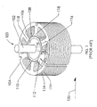
FIG. 1 illustrates a traditional electric motor exemplifying commonly-used stator and rotor structures.Electric motor 100 is a cylindrical motor composed of astator structure 104, amagnetic hub 106 and ashaft 102. The rotor structure ofmotor 100 includes one or morepermanent magnets 110, all of which are attached viamagnetic hub 106 toshaft 102 for rotation withinstator structure 104.Stator structure 104 typically includesfield poles 118, each having a coil winding 112 (only one is shown) that is wound about eachfield pole 118.Stator structure 104 includesslots 108 used in part to provide a wire passage for winding coil wire aboutstator field poles 118 during manufacturing.Slots 108 also provide magnetic separation betweenadjacent field poles 118.Stator structure 104 includes a peripheral flux-carryingsegment 119 as part ofmagnetic return path 116. In many cases,stator structure 104 is composed oflaminations 114, which typically are formed from isotropic (e.g., non-grain oriented), magnetically permeable material.Magnetic return path 116, which is one of a number of magnetic return paths in which permanent magnet-generated flux and AT-generated flux is present, is shown as being somewhat arcuate in nature at peripheral flux-carryingsegment 119 but includes relatively sharp turns into thefield pole regions 118. - One drawback of traditional electric motors, including
electric motor 100, is thatmagnetic return path 116 requires a relatively long length for completing a magnetic circuit for flux emanating from onerotor magnet pole 110 and traversing viamagnetic return path 116 to anotherrotor magnet pole 110. Furthermore,magnetic return path 116 is not a straight line, which is preferred for carrying magnetic flux. As shown,magnetic return path 116 has two ninety-degree turns in the stator path.Magnetic return path 116 turns once fromfield pole region 118 to peripheral flux-carryingsegment 119, and then again from peripheral flux-carryingsegment 119 to anotherfield pole region 118. Both of these turns are suboptimal for carrying flux efficiently. As implemented,magnetic return path 116 requires more material, or "back-iron," than otherwise is necessary for carrying such flux between field poles. Consequently,magnetic return paths 116 add weight and size to traditional electric motors, thereby increasing the motor form factor as well as cost of materials to manufacture such motors. - Another drawback of conventional electric motors is that
laminations 114 do not effectively use anisotropic materials to optimize the flux density and reduce hysteresis losses in flux-carrying poles, such as throughfield poles 118, and stator regions at peripheral flux-carryingsegment 119. In particular, peripheral flux-carryingsegment 119 includes a non-straight flux path, which limits the use of such anisotropic materials in minimizing hysteresis losses (or "iron losses"). Hysteresis is the tendency of a magnetic material to retain its magnetization. "Hysteresis loss" is the energy required to magnetize and demagnetize the magnetic material constituting the stator regions, wherein hysteresis losses increase as the amount of magnetic material increases. Asmagnetic return path 116 has one or more turns of ninety-degrees or greater, the use of anisotropic materials, such as grain-oriented materials, cannot effectively reduce hysteresis losses because themagnetic return path 116 in peripheral flux-carryingsegment 119 would cut across the directional orientation oflaminations 114. For example, ifdirection 120 represents the orientation of grains forlaminations 114, then at least two portions ofmagnetic return path 116 traverse acrossdirection 120 of the grain, thereby retarding the flux density capacity of those portions of stator peripheral flux-carryingsegment 119. Consequently, anisotropic materials generally have not been implemented in structures similar tostator structure 104 since the flux paths are usually curvilinear rather than straight, which limits the benefits provided by using such materials. - Yet another drawback of conventional electric motors is the relatively long lengths of
magnetic return path 116. Changing magnetic fields, such as those developed at motor commutation frequencies, can cause eddy currents to develop inlaminations 114 in an orientation opposing the magnetic field inducing it. Eddy currents result in power losses that are roughly proportional to a power function of the rate at which the magnetic flux changes and roughly proportional to the volume of affected lamination material. - Other drawbacks of commonly-used electric motors include the implementation of specialized techniques for reducing "cogging," or detent torque, that are not well-suited for application with various types of electric motor designs. Cogging is a non-uniform angular torque resulting in "jerking" motions rather than a smooth rotational motion. This effect usually is most apparent at low speeds and applies additive and subtractive torque to the load when
field poles 118 are at different angular positions relative to magnet poles. Further, the inherent rotational accelerations and decelerations cause audible vibrations. - In another type of electric motor, magnetic poles are positioned at relatively large diameters about (or radial distances from) a rotor shaft. These magnetic poles, as well as the permanent magnets giving rise to those magnetic poles, are typically arranged coaxially about the shaft, with adjacent magnetic poles alternating in polarity. An armature disk usually supports the permanent magnets as separate, non-monolithic magnets in a plane perpendicular to the rotor shaft. Structures such as this are designed based on a certain tenet of electric motor design. According to this tenet, an increase in output torque is achieved by increasing the radial distance between the magnetic poles and the rotor shaft. Consequently, the magnetic poles of this type of electric motor are increasingly being positioned at larger distances from the rotor shaft to increase the torque arm distance from the axis of rotation to the air gaps, thereby increasing the output torque. A drawback to this approach is that additional materials are consumed in forming larger motor structures to accommodate the larger torque arm distance, such as those structures that are used to form magnetic flux return paths. These magnetic flux return paths are typically formed using "back-iron" to complete a larger flux path, which is generally circuitous in nature. By adding back-iron to complete a magnetic circuit, the magnetic material volume through which the magnetic flux passes increases, which detrimentally tends to increase the hysteresis and eddy current losses, both of which can be collectively referred to as "core losses." Further, the addition of back-iron to complete a magnetic circuit increases the length of the magnetic flux path, thereby exacerbating core losses. Another drawback to motors of this type is that the motor volume increases as the magnetic poles are positioned farther from the shaft, which, in turn, limits the available applications and uses for this type of motor.
- "Back-iron" is a term commonly used to describe a physical structure (as well as the materials giving rise to that physical structure) that is often used to complete an otherwise open magnetic circuit. Back-iron structures are generally used only to transfer magnetic flux from one magnetic circuit element to another, such as either from one magnetically permeable field pole to another, or from a magnet pole of a permanent magnet to a magnet pole of another permanent magnet, or both. Further, "back-iron" structures are not generally formed to accept an associated ampere-turn generating element, such as one or more coils.
- In view of the foregoing, it would be desirable to provide a rotor-stator structure that minimizes the above-mentioned drawbacks in electric motors and generators, and to increase output torque and efficiency either on a per unit size or per unit weight basis, or both, as well as to conserve resources during manufacturing and/or operation.
- A system according to claim 1 is disclosed for implementing an exemplary rotor-stator structure for use in electrodynamic machines, such as electric motors, generators, alternators, and the like. According to one embodiment of the present invention, a rotor-stator structure for electrodynamic machines comprises conical magnets having conical surfaces arranged axially on an axis of rotation such that the conical surfaces face each other. The conical magnets include at least two conical magnets being positioned so that the directions of polarization of the two conical magnets are in substantially opposite directions. Further, the rotor-stator structure can also include field pole members arranged coaxially to the axis. The field pole members have flux interaction surfaces formed at the ends of the field pole members and adjacent to portions of the conical surfaces that confront the flux interaction surfaces. The flux interaction surfaces define air gaps with the portions of the conical surfaces and are configured to magnetically couple the field pole members to the conical magnets. Preferably, each of the field pole members is spaced from another of the field pole members by a field pole gap. Advantageously, each of the conical magnets establishes an air gap with each of the field pole members. Conveniently, the air gaps, the conical magnets and the field pole members are sufficient to form a closed flux path that passes through at least two of the field pole members in different directions and through the at least two conical magnets in substantially opposite directions. In some cases, the rotor-stator structure includes a shaft on which the conical magnets are affixed, the shaft defining the axis of rotation. The conical surfaces each can have an angle of inclination from about 10 degrees to about 80 degrees with respect to the axis of rotation. In one embodiment, each of the field pole members further comprises a magnetically permeable material that is continuous from one end of each field pole member to the other end, where at least a portion of each field pole member is configured to accept an element, such as one or more coils, for generating ampere-turn ("AT") flux. In an alternative embodiment, the rotor-stator structure further comprises one or more coils, at least one of which is wound about each of the field pole members to form active field pole members. In some cases, the rotor-stator structure excludes back-iron, thereby decreasing hysteresis losses as well as materials for manufacturing an electrodynamic machine. In another embodiment, at least one of the field pole members of a rotor-stator structure is substantially straight. Substantially straight field pole members can provide a relatively short magnetic flux path between magnets, which may be accompanied by a reduction in the volume of the magnetically permeable material as compared to the use of back-iron in some traditional stator structures. By reducing the volume of magnetically permeable material through which magnetic flux is conducted, hysteresis losses can be decreased.
- The field pole members and the conical magnets of an exemplary rotor-stator structure can be arranged to minimize linear deviations in a path portion of a magnetic flux path coincident with a substantially straight line extending from a surface portion of a first conical magnet to a surface portion of a second conical magnet, the path portion terminating at the surface portions. In a specific embodiment, the rotor-stator structure is configured to generate magnetic flux paths consisting essentially of the first conical magnet, the second conical magnet, at least one of the field pole members, and two or more air gaps. The field pole members, in some instances, can comprise laminations to minimize eddy currents, thereby reducing power losses. The laminations can be formed from a substrate composed of a magnetically permeable material in a manner that reduces wastage of the magnetically permeable material. Notably, in certain instances, at least one of the laminations is anisotropic, which can include grain-oriented materials. In one embodiment, the rotor-stator structure further comprises a coil wound about at least one of the field pole members to form at least one active field pole member, where at least the one field pole member is shaped to minimize manufacturing complexity associated with winding the coil on traditional field poles by obviating the need to wind the coil via a slot. In still another embodiment, each of the flux interaction surfaces further comprises a skewed flux interaction surface to reduce field pole gaps between adjacent field pole members, thereby minimizing detent torque. The skewed flux interaction surface may include a first edge defining a first side of a field pole gap and a second edge defining a second side of another field pole gap, whereby the first edge and the second edge maintain angles that do not align with a direction of polarization of at least one of the conical magnets, where one first edge of a first field pole member and one second edge of a second field pole member form the field pole gap. Detent torque can also be reduced by offsetting the directions of polarization of the two conical magnets by about 150 to about 180 degrees. The field pole members, in at least one example of a rotor-stator structure, are stationary while the conical magnets can rotate relative to the field pole members, whereas in other examples, the conical magnets remain stationary and the field pole members rotate relative to the conical magnets.
Advantageously, each of the field pole members may be an elongated field pole member having a length dimension in an axial direction greater than a width dimension. Preferably, said flux path passes through at least two of said field pole members in different directions. Conveniently, the directions of polarisation are configured to form a flux path portion of the closed flux path within the interior of each of the conical magnets, the flux path portion extending through a plane that includes the axis of rotation. Advantageously, the flux path portion extends from a first point to a second point, the first point and the second point lying on conical surface portions associated with the same conical surface. Preferably, the directions of polarization are each substantially perpendicular to the axis of rotation. More preferably, the directions of polarization are each perpendicular to the axis of rotation. - According to another embodiment of the present invention, a rotor-stator structure for electrodynamic machines having an axis comprises a rotor having at least two magnets arranged axially about the axis. The two magnets can be spaced apart from each other and can have regions of predetermined magnetic polarization. The magnets each can have confronting magnetic surfaces of principal dimension that is substantially at an acute angle to the axis. The confronting magnetic surfaces face each other generally, with the magnetic polarizations being in substantially opposite directions. The magnetic polarizations can be described as lying within planes passing through the magnet surfaces while being substantially perpendicular to the axis. In one embodiment, the magnets are substantially conical magnets and the magnetic surfaces are conical magnetic surfaces. The rotor-stator structure can also include field poles arranged coaxial to the axis and having flux interaction surfaces formed at the ends of the field poles. The flux interaction surfaces are typically located adjacent the confronting magnetic surfaces, which are generally coextensive with the principal dimension thereof, defining functioning air gaps therewith. Each of the field pole members can be magnetically permeable, wherein the flux interaction surfaces are configured to magnetically couple the field pole members to the conical magnets. In at least one instance, one or more field pole members each further comprises a coil about the one or more field pole members, thereby forming one or more active field pole members. In one embodiment, the rotor-stator structure is configured to limit magnetic flux paths to traverse only through two of the conical magnets, the field pole members, the flux interaction surfaces, and the air gaps. As such, back-iron is excluded. In a specific embodiment, the field pole members comprise one or more of silicon-iron alloys, nickel-iron alloys, cobalt-nickel alloys, magnetic-powdered alloys, and soft magnetic composite, whereas the conical magnets can be permanent magnets composed of a magnet material having a recoil permeability less than 1.3. As an example, the conical magnets can be composed of neodymium iron ("NdFe"), in whole or in part. As other example, the magnets can be composed of ceramic, Samarium Cobalt ("SmCo"), or any other rare earth magnet material.
- According to yet another embodiment of the present invention, an exemplary rotor-stator structure for electrodynamic machines comprises a shaft defining an axis of rotation and having a first end portion, a central portion and a second end portion. The rotor-stator structure includes at least a first magnet having a surface contoured as at least a portion of a cone to form a first conical surface, the first magnet having a first direction of polarization and being disposed axially on the shaft at the first end portion. Also, the rotor-stator structure can include a second magnet having a surface contoured as at least a portion of a cone to form a second conical surface, the second magnet having a second direction of polarization and being disposed axially on the shaft at the second end portion such that the first direction of polarization is substantially opposite to the second direction of polarization. Generally, the second conical surface faces, or confronts, the first conical surface. The rotor-stator structure is further composed of a number of field pole members arranged substantially coaxial to the shaft. Each of the field pole members comprises a number of substantially straight laminations, at least one of which is composed of anisotropic material and arranged in parallel with other laminations and in parallel with the axis of rotation. Each of the field pole members has a first pole shoe at its first field pole member end and a second pole shoe at its second field pole member end, the first pole shoe being positioned adjacent to a portion of the first conical surface to form a first flux interaction region and the second pole shoe being positioned adjacent to a portion of the second conical surface to form a second flux interaction region. Further, the rotor-stator structure includes at least one coil wound about at least one of the number of field pole members to form an active field pole member. As such, at least in some cases, the rotor-stator structure is configured to generate at least one magnetic flux path limited to traverse only through the first magnet, the second magnet, the active field pole member and the first and second flux interaction regions. In a specific embodiment, the at least one coil extends substantially the length of the active field pole member in an axial direction for reducing flux leakage from the peripheries of the active field pole member.
- In an alternate embodiment, the first pole shoe and the second pole shoe further comprise a first pole face and a second pole face, respectively, wherein at least a portion of the first pole face is contoured to form a first air gap having a gap thickness principally defined by the distance between the portion of the first conical surface and the first pole face, and at least a portion of the second pole face is contoured to form a second air gap having a gap thickness principally defined by the distance between the portion of the second conical surface and the second pole face. The gap thickness is generally no greater than 40% of an average diameter of either the first magnet or the second magnet. In another embodiment, the first magnet and the second magnet each are dipole magnets oriented in a manner so their polarizations differ by an angle between 150 to 180 degrees, wherein each of the dipole magnets is monolithic. In some embodiments, the first magnet and the second magnet each are multipole magnets. An exemplary configuration for a rotor-stator includes three or four field poles and dipole magnets. Another configuration includes six or eight field poles configured to operate with four-pole conical magnets. The rotor-stator structure, in some instances, can be configured to receive electrical power as an electrical current into the at least one coil for implementing an electric motor. In other instances, the rotor-stator structure can be configured to receive mechanical power as rotational motion about the shaft for implementing an electric generator.
- According to still yet another embodiment of the present invention, an exemplary rotor-stator structure for electrodynamic machines comprises a shaft defining an axis of rotation, at least two permanent magnets each having at least one conical surface and an outer surface, each of the at least two permanent magnets being affixed coaxially on the shaft such that one of the at least one conical surface faces another, a plurality of sets of coils, and a plurality of ferromagnetic field pole members. The plurality of ferromagnetic field pole members are disposed substantially parallel to the axis, each of the ferromagnetic field pole members having a length along an axial direction, the length substantially extending at least between both of the at least one conical surface of the at least two permanent magnets. Each of the ferromagnetic field pole members also has at least a central portion around which a set of coils of the plurality of sets of coils is wound. Each of the ferromagnetic field pole members has a pole shoe having at least a pole face formed at each end of the ferromagnetic field pole members. Each pole face is generally configured to form a flux interaction region with or via a portion of the at least one conical surface of either one of the at least two permanent magnets.
- According to at least one embodiment, an exemplary rotor-stator structure can be disposed within an electric motor to provide more output torque deliverable by such a motor relative to conventional electric motors of the same size and/or weight. In one embodiment, a rotor-stator structure provides a relatively shorter and straighter magnetic path, and a more efficient use of materials than traditional stator-rotor structures for electrodynamic machines. In cases where anisotropic (e.g., grain-oriented materials) magnetically permeable materials are used to form field pole members of specific embodiments of the present invention, the inherent magnetic properties of such materials contribute to an increase of flux density in flux-carrying regions. Note that these materials may or may not be used to form laminations. The elimination or at least reduction of exterior return paths, such as those return paths traditionally implemented using back-iron, therefore saves weight and reduces the overall size of electrodynamic machines implementing various embodiments of the rotor-stator structure of the present invention. In another embodiment, a stator-rotor structure provides a greater motor efficiency than a similarly-sized conventional motor with the same output torque. This efficiency increase is due, at least in part, to lower resistance windings, which translates to lower current-squared-times-resistance (i.e., I2 * R) power losses while producing the same ampere turn-generated flux created in similarly-sized packages or motor housings of traditional motors. Further, the rotor-stator structure of the present invention is less complex (e.g., in the coil winding process) and less costly (e.g., due to conservation of materials) to manufacture than conventional motors.
- The invention is more fully appreciated in connection with the following detailed description taken in conjunction with the accompanying drawings, in which:
-
FIG. 1 exemplifies commonly-used stator and rotor structures implemented in a traditional electric motor; -
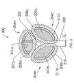
FIG. 2 is an exploded view of an exemplary rotor-stator structure in which the magnets are conical in shape, according to one embodiment of the present invention; -
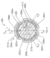
FIG. 3 depicts an end view for the rotor-stator structure ofFIG. 2 without a magnet to illustrate the orientation of the pole faces that are configured to interact via an air gap with a confronting magnetic surface of a conical magnet, according to one embodiment of the present invention; -
FIG. 4 depicts another end view for the rotor-stator structure ofFIG. 2 illustrating a conical magnet positioned adjacent to pole faces in accordance with an embodiment of the present invention; -
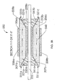
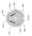
FIGs. 5A and5B depict sectional views illustrating an exemplary magnetic flux path, according to at least one embodiment of the present invention; -
FIG. 5C depicts an example of a second flux path exiting a pole face of a stator member generating an ampere-turn magnetic flux, according to one embodiment of the present invention; -
FIG. 5D depicts an example of a second flux path(s) entering a pole face of an active field pole member that originally generated the ampere-turn magnetic flux ofFIG. 5C , according to one embodiment of the present invention; -
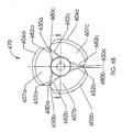
FIGs. 6A and6B illustrate an end view of another exemplary rotor-stator structure, according to another embodiment of the present invention; -
FIG. 6C depicts a partial sectional view of the rotor-stator structure ofFIGs. 6A and6B , according to one embodiment of the present invention; -
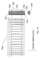
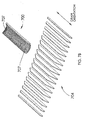
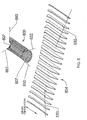
FIGs. 7A and7B illustrate an exemplary field pole member, according to an embodiment of the present invention; -
FIG. 8 illustrates another exemplary field pole member having skewed pole faces, according to a specific embodiment of the present invention; -
FIGs. 9A to 9M illustrate examples of other-shaped permanent magnets that can be implemented in an exemplary rotor-stator structure, according to various embodiments of the present invention; -
FIG. 10 shows a multiple pole magnet, according to an embodiment of the present invention; and -
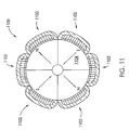
FIG. 11 shows an end view for an example of another rotor-stator structure as an alternate embodiment of the present invention. - Like reference numerals refer to corresponding parts throughout the several views of the drawings. Note that most of the reference numerals include one or two left-most digits that generally identify the figure that first introduces that reference number.
- The following definitions apply to some of the elements described with respect to some embodiments of the invention. These definitions may likewise be expanded upon herein.
- As used herein, the term "air gap" refers to a space, or a gap, between a magnet surface and a confronting pole face. Such a space can be physically described as a volume bounded at least by the areas of the magnet surface and the pole face. An air gap functions to enable relative rotation between a rotor and a stator, and to define a flux interaction region. Although an air gap is typically filled with air, it need not be so limiting.
- As used herein, the term "back-iron" commonly describes a physical structure (as well as the materials giving rise to that physical structure) that is often used to complete an otherwise open magnetic circuit. In particular, back-iron structures are generally used only to transfer magnetic flux from one magnetic circuit element to another, such as either from one magnetically permeable field pole member to another, or from a magnet pole of a first magnet to a magnet pole of a second magnet, or both, without an intervening ampere-turn generating element, such as coil, between the field pole members or the magnet poles. Furthermore, back-iron structures are not generally formed to accept an associated ampere-turn generating element, such as one or more coils.
- As used herein, the term "coil" refers to an assemblage of successive convolutions of a conductor arranged to inductively couple to a magnetically permeable material to produce magnetic flux. In some embodiments, the term "coil" can be described as a "winding" or a "coil winding."
- As used herein, the term "coil region" refers generally to a portion of a field pole member around which a coil is wound.
- As used herein, the term "core" refers to a portion of a field pole member where a coil is normally disposed between pole shoes and is generally composed of a magnetically permeable material for providing a part of a magnetic flux path.
- As used herein, the term "field pole member" refers generally to an element composed of a magnetically permeable material and being configured to provide a structure around which a coil can be wound (i.e., the element is configured to receive a coil for purposes of generating magnetic flux). In some embodiments, a field pole member includes a core (i.e., core region) and at least two pole shoes, each of which is generally located at or near a respective end of the core. But note that in other embodiments, a field pole member includes a core and only one pole shoe. Without more, a field pole member is not configured to generate ampere-turn flux. In some embodiments, the term "field pole member" can be described generally as a "stator-core." In some embodiments, a field pole member generally has an elongated shape such that the length of the field pole member (e.g., the distance between the ends of the field pole member) is generally greater than its width (e.g., the width of the core).
- As used herein, the term "active field pole member" refers to an assemblage of a core, one or more coils, and at least one pole shoe. In particular, an active field pole member can be described as a field pole member assembled with one or more coils for selectably generating ampere-turn flux. In some embodiments, the term "active field pole member" can be described generally as a "stator-core member."
- As used herein, the term "ferromagnetic material" refers to a material that generally exhibits hysteresis phenomena and whose permeability is dependent on the magnetizing force. Also, the term "ferromagnetic material" can also refer to a magnetically permeable material whose relative permeability is greater than unity and depends upon the magnetizing force.
- As used herein, the term "field interaction region" refers to a region where the magnetic flux developed from two or more sources interact vectorially in a manner that can produce mechanical force and/or torque relative to those sources. Generally, the term "flux interaction region" can be used interchangeably with the term "field interaction region." Examples of such sources include field pole members, active field pole members, and/or magnets, or portions thereof. Although a field interaction region is often referred to in rotating machinery parlance as an "air gap," a field interaction region is a broader term that describes a region in which magnetic flux from two or more sources interact vectorially to produce mechanical force and/or torque relative to those sources, and therefore is not limited to the definition of an air gap (i.e., not confined to a volume defined by the areas of the magnet surface and the pole face and planes extending from the peripheries between the two areas). For example, a field interaction region (or at least a portion thereof) can be located internal to a magnet.
- As used herein, the term "generator" generally refers to an electrodynamic machine that is configured to convert mechanical energy into electrical energy regardless of, for example, its output voltage waveform. As an "alternator" can be defined similarly, the term generator includes alternators in its definition.
- As used herein, the term "magnet" refers to a body that produces a magnetic field external to itself. As such, the term magnet includes permanent magnets, electromagnets, and the like.
- As used herein, the term "motor" generally refers to an electrodynamic machine that is configured to convert electrical energy into mechanical energy.
- As used herein, the term "magnetically permeable" is a descriptive term that generally refers to those materials having a magnetically definable relationship between flux density ("B") and applied magnetic field ("H"). Further, "magnetically permeable" is intended to be a broad term that includes, without limitation, ferromagnetic materials, soft magnetic composites ("SMCs"), and the like.
- As used herein, the term "pole face" refers to a surface of a pole shoe that faces at least a portion of the flux interaction region (as well as the air gap), thereby forming one boundary of the flux interaction region (as well as the air gap). In some embodiments, the term "pole face" can be described generally as a "stator surface."
- As used herein, the term "pole shoe" refers to that portion of a field pole member that facilitates positioning a pole face so that it confronts a rotor (or a portion thereof), thereby serving to shape the air gap and control its reluctance. The pole shoes of a field pole member are generally located near each end of the core starting at or near a coil region and terminating at the pole face. In some embodiments, the term "pole shoe" can be described generally as a "stator region" or at least a portion of a "flux interaction surface," or both.
- As used herein, the term "soft magnetic composites" ("SMCs") refers to those materials that are comprised, in part, of insulated magnetic particles, such as insulation-coated ferrous powder metal materials that can be molded to form an element of the rotor-stator structure of the present invention.
-
FIG. 2 is an exploded view of an exemplary rotor-stator structure in accordance with a specific embodiment of the present invention. In this example, rotor-stator structure 200 is configured to increase torque generated per unit size (or per unit weight) for electric motor implementations by at least minimizing the length of magnetic flux paths through field pole members. In some embodiments, field pole members 204 provide straight or substantially straight flux paths (or segments thereof) to minimize linear deviations of the magnetic flux. Typically, the path segments are generally parallel to the axis of rotation. So by implementing straight or substantially straight paths, each of those field pole members provide a relatively low reluctance flux path as compared to conventional magnetic return path designs that require magnetic flux to turn sharply about the periphery, such as at an angle of ninety-degrees (or thereabout), between field pole regions. As such, rotor-stator structures of various embodiments of the present invention can implement straight or substantially straight paths to enable electrodynamic machines to operate with reduced magnetic losses and increased efficiency. The following description is applicable to magnets having other shapes than or equivalents to conical magnet shapes. - In this example, rotor-
stator structure 200 includes arotor assembly 202 and a number of active field pole members 204 (i.e., activefield pole members rotor assembly 202.Rotor assembly 202 includes two conical magnets 220 (i.e.,conical magnets shaft 222 such that at least a portion of aconical magnet surface 221 a onconical magnet 220a faces at least a portion of aconical magnet surface 221b onconical magnet 220b. In particular, the smaller-diameter ends (i.e., nearest the cones' vertices, if present, or nearest the cones' conceptual vertices if otherwise not present due to, for example, truncation of the cone) of the conical magnets 220 face each other. Further, conical magnets 220 are each positioned adjacent to one group of ends of active field pole members 204. In various embodiments of the present invention,conical magnet surfaces shaft 222 can be composed of magnetically permeable material, while in other embodiments it can be made of non-magnetic and/or non-electrically conductive materials. As such, rotor-stator structure 200 does not requireshaft 222 to form flux paths. Active field pole members 204 andconical magnets - Each of active field pole members 204 includes a field pole member 206 and an insulated coil 208 wrapped around a respective field pole member 206. Field pole members 206 are positioned coaxial about an axis of rotation, which can be defined by the axis of
shaft 222.Coils field pole members conical magnet 220a. For example,pole face 207b is a concave surface resembling the curvature of that of a convex surface ofconical magnet 220a. In one embodiment of the present invention, an optional extended end, such as anextended end 211b, extends longitudinally from field pole members 206 to extend over and/or past outer surfaces of conical magnets 220. As another example,extended end 217b is configured to extend past the outer surface ofconical magnet 220b for insertion into one ofgrooves 242 to construct rotor-stator structure 200. Note that in some embodiments,extended end 211b is omitted (as is other extended ends of field pole members 206 that are not shown), thereby extending the larger-diameter ends of the magnets to or beyond a radial distance associated with the outer surfaces of field pole members 206. - As either
rotor assembly 202 or the number of active field pole members 204 can be configured to rotate in relation to the other, rotor-stator structure 200 can optionally includebearings 230 and both afront mounting plate 240a and arear mounting plate 240b. In a specific embodiment, mountingplates Cavities 244 in mountingplates bearings 230, andgrooves 242 are designed to receive at least a portion of an extended end, such asextended end 217b, of an active field pole member. In some cases,grooves 242 confine the movement of active field pole members 204 to maintain a proper position with respect torotor assembly 202. A protective housing (not shown) can be added to protect bothrotor assembly 202 and field pole members 204 and can also serve as a heat sink for one or more coils 208. While useful to implement the exemplary rotor-stator structure 200, various embodiments of the invention are not limited to including mountingplates bearings 230 andgrooves 242, especially when generating a flux path in accordance with various embodiments of the present invention. - Note that although each field pole member 206 is shown to be wrapped by insulated coil 208, fewer than all of field pole members 206 can be wrapped by coil 208, according to a specific embodiment. For example, coils 208b and 208c can be omitted from active
field pole members coils coils members field pole members field pole members field pole members field pole members shaft 222, thereby decreasing the volume of an electrodynamic machine implementing rotor-stator structure 200. As used herein, a "non-straight" flux path in some embodiments can be described as a flux path having two consecutive segments and at an angle between 60 degrees and 90 degrees. In some embodiments, the term "substantially straight" can refer to a field pole member that provides straight flux paths (e.g., paths that have no deviation from a straight line between, for example, field interaction regions) as well as flux paths that include two consecutive flux path segments that are 60 degrees or less from each other in the same general direction. - In at least one specific embodiment, each of one or more active field pole members 204 include only one or more coils 208 and a field pole member, such as any of 206a, 206b and 206c. In some cases, active field pole members 204 can include tape, paper, and/or paint, or the like that do not add substantial support for coil windings that are wound about a field pole member. Generally, the windings of one or more coils 208 are wound directly on the field pole member itself. The conductors of one or more coils 208 can generally include insulation. But in this specific embodiment, each of active field pole members 204 need not include any other intermediate structure, such as a coil carrier structure, which requires additional material cost and labor during a manufacturing process.
-
FIG. 3 depicts anend view 300 of rotor-stator 200 illustrating orientation of the pole faces that are configured to interact via an air gap with a confronting magnetic surface ofconical magnet 220a, according to one embodiment of the present invention. Absent fromFIG. 3 is front mountingplate 240a,bearings 230 andconical magnet 220a, all of which are omitted to depict the end views of both the active field pole member and coil shapes, as well as the field pole gaps ("G") between the field poles. As shown,coils field pole members field pole members slots 108 ofFIG. 1 ).FIG. 3 also depicts edges ofextended ends pole faces field pole members conical magnet 220a. Further, field pole gaps are defined by the sides (or edges) of the field pole members that constitute activefield pole members planes field pole members FIG. 2 ). -
FIG. 4 depicts anotherend view 400 of rotor-stator 200 andconical magnet 220a positioned adjacent topole faces FIG. 3 ) in accordance with an embodiment of the present invention. As shown,outer magnet surface 223a ofconical magnet 220a is visible, as are the protruding edges ofextended ends conical magnet 220a is a dipole magnet (e.g., a permanent magnet) having a north pole ("N") and a south pole ("S"). Note that in some embodiments,conical magnets FIG. 4 defines three sectional views. The first sectional view, X-X, cuts straight through as a centerline bisectingfield pole member 206a andcoil 208a and then passes viamagnet 220a through a field pole gap between otherfield pole members field pole member 206a andcoil 208a and then passes viamagnet 220a throughfield pole member 206b andcoil 208b. A third view section view, Y'-Y', which is similar to the second section view, Y-Y, bisectsfield pole member 206a andcoil 208a and then passes viamagnet 220a throughfield pole member 206c andcoil 208c. Section view X-X is shown inFIG. 5A , whereas views Y-Y and Y'-Y' produce similar drawings, both of which are depicted inFIG. 5B . -
FIGs. 5A and5B depict sectional views illustrating an exemplary magnetic flux path, according to at least one embodiment of the present invention.FIG. 5A depicts a cross section of activefield pole member 204a of rotor-stator structure 500, the cross section showing a sectional view X-X ofcoil 208a andfield pole member 206a. In this example, activefield pole member 204a includes pole faces 307a and 505b,pole shoes coil region 506 andcoil 208a. In view X-X ofFIG. 5A ,conical magnets respective pole shoes field pole member 206a. Correspondingly,pole face 307a ofpole shoe 507a forms amagnetic air gap 551a with at least aportion 521a ofmagnet surface 221 a, withportion 521a confrontingpole face 307a and shown as a cross-section. Similarly,pole face 505b ofpole shoe 507b forms amagnetic air gap 551b with at least aportion 521b ofmagnet surface 221b, withportion 521b confrontingpole face 505b and shown as a cross-section. Note thatportions conical magnets portions conical magnets portions conical magnets coil 208a encloses acoil region 506 offield pole member 206a, wherebycoil region 506 is defined approximately by the axial length ofcoil 208a surrounding a portion offield pole member 206a. Absent inFIG. 5A is a depiction of one or more field interaction regions, which can encompass a space larger than an air gap, such asair gap 551a, and can extend into, for example,conical magnet 220a. - In at least one embodiment of the present invention, at least one of
magnet portions conical magnets shaft 222. In a specific embodiment, angle of inclination ("θ") 501 is 30 degrees fromshaft 222. But note thatangle 501 can be any angle. - With opposite polarizations,
conical magnet 220a is polarized with its north pole ("N") pointing indirection 502, andconical magnet 220b is polarized with its north pole ("N") pointing indirection 504. In some embodiments,conical magnets directions 502 and 504). But in other embodiments,directions directions conical magnets -
FIG. 5B depicts cross sections of activefield pole member 204a and either activefield pole member 204b or activefield pole member 204c, and depicts a magnetic flux path, according to one embodiment of the present invention. For ease of discussion, only view Y-Y will be discussed. View Y-Y is sectional view ofcoil 208a andfield pole member 206a passing thoughcoil 208b andfield pole 206b.Magnetic flux path 560 passes through bothfield pole members conical magnets Conical magnets conical magnet 220a and crossesair gap 551a to enterpole face 307a (FIG. 3 ), the north pole coinciding withsurface portion 521a, which confrontspole face 307a. The first flux path then traverses longitudinally throughfield pole member 206a and then exitspole face 505b at the end offield pole member 206a adjacent toconical magnet 220b. The first flux path continues by crossingair gap 551b and enters the south pole ("S") ofconical magnet 220b, the south pole generally coinciding with asurface portion 521b of magnet surface 22Ib and confrontspole face 505b. The first flux path passes throughconical magnet 220b to its north pole, which generally coincides with asurface portion 561b ofmagnet surface 221b that confrontspole face 213b. Next, the first flux path crossesair gap 551c and enterspole face 213b (FIG. 2 ). From there, the first flux path returns throughfield pole member 206b topole face 207b from which it exits, crossesair gap 551d, and then enters the south pole ofconical magnet 220a, thereby completing the first flux path. Generally, the south pole ofconical magnet 220a coincides with asurface portion 561a ofmagnet surface 221a (FIG. 2 ) that is confrontingpole face 207b. Note that in the case shown, the flux exitingpole face 207b is equivalent to that flux exitingpole face 207c. Note that no supplemental structure or material need be required to form any portion ofmagnetic flux path 560. As such, rotor-stator structure 550 does not include back-iron. - In a specific embodiment, the diameters of conical magnets 220 are set so that the length of the flux path in each of conical magnets 220 is relatively large with respect to the four
air gaps 551a to 551d, thereby establishing a favorable magnet load line. Note that each of the fourair gaps 551 a to 551d provides for a flux interaction region to facilitate magnetic flux interaction between (or through) pole faces and the magnet. Note further that a flux path in eitherconical magnet - In at least one embodiment, rotor-stator structure 550 (
FIG. 5B ) generates at least a portion ofmagnetic flux path 560 that extends substantially linearly from aboutsurface portion 521 a of the magnet surface of firstconical magnet 220a to aboutsurface portion 521 b of the magnet surface of secondconical magnet 220b. In one instance, the portion of the magnetic flux path consists essentially ofsurface portion 521a of firstconical magnet 220a,surface portion 521 b of the secondconical magnet 220b, at least one of the field pole members, such asfield pole member 206a, and two or more air gaps, such asair gaps - In at least one embodiment of the present invention,
conical magnets conical magnet conical magnet conical magnet - Magnet materials are often characterized in part by a maximum energy product of such materials. In addition, magnet materials may be characterized by "Br," which is the magnetic flux density output from a magnet material when measured in a closed circuit and no measured external magnetic fields are being applied to that magnetic material. That maximum flux density value is frequently denoted as "Br." A high value of Br indicates that a magnet material is capable of large magnetic flux production per pole area (i.e., a high flux density). In at least one embodiment,
conical magnets - In various embodiments,
conical magnets conical magnets - While various embodiments of the present invention cover a multitude of design motor and/or generator designs using any of known available magnet materials, at least one embodiment uses magnet materials with low ratios of values of B to values of adverse applied field intensity, H, such ratios, as is typically specified in many magnet material data sheets, being measured at the respective material's Br point, those ratios defining the "recoil permeability at Br" of such materials. While in some cases magnet materials need not only be limited to high values of coercivity, the magnet materials should exhibit predictable output flux densities when subjected to expected adverse magnetic field or thermal conditions. As such, the value of "recoil permeability" can be at least one factor when considering a motor and/or generator design using an exemplary rotor-stator structure, according to one embodiment of the present invention.
- Recoil permeability is generally an expression of the relationship between values of B and the values of adverse applied field intensity. The values of recoil permeability are typically evaluated in terms of CGS units (because the permeability of air is 1.0 in CGS units) and can be determined by dividing a value of B (e.g., expressed in Tesla), near or at Br, by a value of adverse applied field intensity (e.g., H, near or at Hc, expressed in Oerstead). For some magnet materials, an average recoil permeability value can be determined and may be useful in magnet material selection. In one embodiment, recoil permeability can be defined for various magnetic materials by Magnetic Materials Producers Association ("MMPA") Standard 0100-00, as maintained by the International Magnetics Association ("IMA"). Note that (dimensionless) relative recoil permeability can also be given when using S.I. units.
- Generally, values of recoil permeability are not less than 1.0. The closer that a recoil permeability value is to 1.0, however, the higher the coercivity can be for a specific measured material. In most embodiments of the present invention, a value of recoil permeability is typically less than 1.3. Typical high-coercivity magnet materials, such as magnets composed of neodymium-iron ("NdFe") and variants thereof, can have a recoil permeability value of about 1.04 in CGS units. An example of such a variant is Neodymium-Iron-Boron, or "NdFeB." Common low-cost ceramic magnets, such as those composed of ferrite ceramic, can have a ratio value of about 1.25, which permits ceramic magnets to perform adequately in most applications. Note that the average recoil permeability of typical high performance ceramic magnets is usually within a range of 1.06 to 1.2 in CGS units, more or less.
- Coils 208 wound around each of field pole members 206 form the second flux path. In this example, the flux generated by the ampere-turns in
coils FIG. 5B travels in a similar path to the permanent magnet flux, with the exception thatconical magnets field pole member 206a (e.g., within coil region 506) is present at the pole faces adjacent toconical magnets FIGs. 5A and5B . - In at least one specific embodiment, coils 208 can include foil conductors that are conductors having a rectangular cross-section with a relatively large width and a relatively small height. Foil conductors with insulation between layers can be used in place of wire to decrease winding resistance and increase current handling capacity in the same available winding volume. Use of a foil conductor can also decrease the inductance of the winding. In one embodiment, the insulation is affixed to one side of the foil to isolate the foil conductor in subsequent windings around the core. That is, only one side of the foil conductors need be insulated since that one side insulates a non-insulated side of a previous wound portion of the foil conductor (or foil coil). Advantageously, this reduces the amount of insulation required for coils 208, thereby saving resources, increasing packing density and increasing the number of ampere turns (while decreasing the number of conductor turns) in a space otherwise filled by fully insulated conductors (i.e., insulated on all sides, such as an insulated wire). As the foil conductor also provides for relatively smaller bending radii, it can thereby decrease the winding resistances usually common in conductors having sharper bends. By decreasing the resistance, this type of conductor can also conserve power in generating amp-turn flux, especially in battery-powered motor applications.
-
FIG. 5C depicts an example of a second flux path exiting a pole face of the active field pole member that generates that ampere-turn magnetic flux, according to one embodiment of the present invention. In this figure, ampere-turn ("AT")-generated flux is generated in activefield pole member 204a and then exits frompole face 513a ofFIG. 5C (or as shown aspole face 505b inFIG. 5B ) while dividing approximately in half to formflux turn flux 570a enterspole face 213b, and ampere-turn flux 570b enterspole face 513c. Then, respective portions of the second flux path then travel longitudinally through the other field pole members (e.g.,field pole members field pole member 204a, which initially generated the second flux path. -
FIG. 5D depicts an example of the second flux path(s) returning to a pole face of the active field pole member that generated the ampere-turn magnetic flux, according to one embodiment of the present invention. As shown, ampere-turnmagnetic flux pole face 307a, thereby completing the magnetic circuit of the second flux path (i.e., the ampere-turn magnetic flux path). - Conceptually, the magnetic fields generated by the ampere-turns in each field pole member of active
field pole members FIG. 5D can be viewed as regions of magnetic potential at each of the pole faces at the end regions or pole shoes of the active field pole members. In the air gaps between the confronting surfaces of the conical magnets and their adjacent pole faces, the flux of the first flux path and the flux of the second flux path interact in a manner familiar to those skilled in the art, where such an interaction is useful to generate torque by an electric motor implementing rotor-stator structure 200, according to at least one embodiment of the present invention. The first and the second flux paths of rotor-stator structure 200 are efficient, at least in part, because the flux is contained within the core regions 506 (FIG. 5A ) of field pole members 206 by the currents running through coils 208. The magnet flux generated by each of the conical magnets 220 interacts in a flux interaction region with the magnetic flux from pole faces of active field pole members 204. As such, flux leakage paths, if any, are generally limited to relatively very small regions atpole shoes FIG. 5A ), both of which include the sides and the backs of field pole members 206. As the first and second flux paths are also mostly straight in the magnetically permeable material of field pole members 206, these field pole members are well suited to be implemented with anisotropic (e.g., grain-oriented), magnetic materials in an efficient manner. As such, field pole members 206 can be composed of any anisotropic, magnetic materials capable of carrying higher flux densities and lowering magnetic losses in the direction of magnetic orientation, such as along the grains of grain-oriented materials, as compared to the use of isotropic, non-grain oriented, magnetic materials. - To illustrate, consider that an exemplary anisotropic (e.g., grain-oriented) material can have a magnetic saturation value of at least 2.03 Tesla (20,300 Gauss), whereas a typical isotropic lamination material, such as "MI9" laminations, have a saturation value of 1.96 Tesla (19,600 Gauss). Moreover, the applied field required for the anisotropic material to reach saturation is only 10,000 A/m (126 Oerstead) as compared to 36,600 A/m (460 Oerstead) for the isotropic material. Core losses for the anisotropic grain-oriented material (e.g., laminations of 0.36 mm (0.014 inch) thick) can be about 1.46 m2 s-3 (0.66 Watts per pound) at 60 Hz with 1.50 Tesla (15,000 Gauss) induction. By contrast, a typical isotropic material can have core losses of about 3.62 m2 s-3 (1.64 Watts per pound) under similar conditions. In view of the foregoing, the use of anisotropic materials in forming field pole members 206 is advantageous over the use of isotropic materials. According to at least one embodiment, a relatively straight shape for field pole members 206 enables effective use of anisotropic materials, unlike magnetic flux paths of traditional motors.
- Unlike output torque generation of conventional motors, the output torque generated by rotor-
stator structures 200 of various embodiments of the present invention need not be proportional to the radius from the axis of rotation ofshaft 222 to theactive air gaps 551a to 551d (FIG. 5B ). All other factors being the same, increasing the radial distance of the pole faces and air gaps fromshaft 222 does not change the output torque in the way that traditional motor design formulas indicate. For example, traditional motor design concepts teach that the regions carrying ampere-turn flux should be designed to have low reluctance paths, including the part of the ampere-turn magnetic flux path that is the air gap. According to various embodiments of the present invention, the ampere-turn flux path has a relatively high reluctance path through the space occupied by permanent magnets, such as conical magnets 220, yet peak torque production is relatively high in comparison to that of most traditional motors of the same size or weight (again, with other factors being equal). In a specific embodiment, the magnet materials that constitute conical magnets 220 have a magnet permeability value similar to that of air, and as such, the volume of each conical magnet 220 appears as an additional air gap to the ampere-turn magnetic circuit. In at least one embodiment, the output torque generated by an electrodynamic machine is proportional, in whole or in part, to the volumes of conical magnets 220. - In operation of rotor-
stator structure 200, coils 208 are sequentially energized to cause rotation ofrotor assembly 202. The energized coils generate magnetic potentials at the pole faces. These magnetic potentials tend to re-orient the internal field directions of the magnets (e.g., conical magnets 220) to the direction of the applied external field. The external field, in effect, presents an angularly-directed demagnetizing field to conical magnets 220 such that the demagnetizing field is capable of reaching relatively large amplitudes when a motor implementing rotor-stator structure 200 is under high torque loads. The intense demagnetizing field can detrimentally re-magnetize magnet materials of conical magnets 220 that have insufficient coercivity. For this reason, at least one embodiment of the present invention uses magnet materials suited for high torque loading and have: (1) a low B-to-adverse-applied-field intensity ratio, and (2) a relatively low recoil permeability, such as less than 1.3, for example. - In an embodiment of the present invention, the produced torque is through the natural inclination of the magnets, such as conical magnets 220, to seek the lowest energy position. Accordingly, the magnet poles of conical magnets 220, which can be permanent magnets, tend to rotate toward regions of greatest magnetic attraction and away from regions of magnetic repulsion, whereby such regions of "magnetic potential" are created at the air gaps at both ends of energized active field pole members 204 by the ampere-turn generated magnetic fields. Since a magnet having a relatively high coercivity will resist attempts to angularly displace the direction of its internal magnetic field, this resistance to angular displacement is manifested as mechanical torque on the body of the permanent magnet, thereby transferring torque to the shaft As such, the magnets (e.g., conical magnets 220) can develop and then transfer torque to the shaft as useful output torque applied to a load.
-
FIGs. 6A ,6B and6C illustrate anend view 600 of another exemplary rotor-stator structure, according to another embodiment of the present invention.FIGs 6A and6B show end views 600 of a rotor-stator structure whileFIG. 6C is a partial sectional view A-A ofFIG. 6B .FIG. 6A shows active field pole members 604 each having a skewed pole face 607 at an end of a respective field pole member 606. Each skewed pole face 607 has a contoured surface that generally tracks the surface characteristics of that of a confronting surface portion of an adjacent magnet, such asconical magnet 220a, to form an air gap having, for example, a relatively constant air gap thickness. Air gap thickness generally refers to the orthogonal distance between a pole face and a confronting surface of a magnet. The skewed pole faces 607 are, at least in part, defined by surface edges and/or sides of field pole members 606 that are slightly angled or skewed with respect to the magnetization direction (e.g., direction of polarization) of an adjacent magnet. Skewed edges and/or sides are shown inFIG. 6A as first skewed edges 650 and second skewed edges 652, both of which are configured as edges of field pole members 606 to form skewedfield pole gaps 660 when active field pole members 604 are arranged in a rotor-stator structure. As an example, consider that firstskewed edge 650c is configured to form anangle 622 with respect to at least one direction ofpolarization 630 of a magnet (not shown). Consider further that secondskewed edge 652b is configured to form anangle 620 with respect to direction ofpolarization 630.Angles field pole gaps 660 that are skewed in relation to the directions of polarization of one or more magnets. Note thatFIG. 6C is a partial sectional view showing skewed edges being configured so that the radial plane ofmagnetic polarization 631 does not align with either of field pole edge 650 or field pole edge 652. In particular,field pole edge 650c andfield pole edge 652b both do not align (i.e., are skewed) relative to plane ofmagnetization 631. -
FIG. 6B is anend view 670 showing skewed pole face edges at both ends of field pole members 606. By implementing skewedfield pole gaps 660 ofFIG. 6A in a rotor-stator structure, detent torque ("cogging") is reduced. In at least one embodiment, skewedfield pole gaps 660 are adapted for use with permanent magnets that are diametrically polarized, such as conical magnets 220. In this instance,end view 670 ofFIG. 6B is an end view showing pole faces 607 that are configured to surface contours similar to that of an adjacentconical magnet 220a, pole faces 607 being similar to those shown inFIG. 6A . Also shown inFIG. 6B are first skewed edges 680 and second skewed edges 682, which are associated with pole faces at the other end of field pole members 606 (e.g., at the other pole shoe opposite than that associated with first skewed edges 650 and second skewed edges 652 as indicated by the broken lines). First skewed edges 680 and second skewed edges 682 in this case have angles similar to those of first skewed edges 650 and second skewed edges 652, respectively, but face a magnet surface associated withconical magnet 220b, for example. As such, the angular directions of the field pole gaps formed by edges 650 and 652 are opposite in the angular direction of the field pole gaps formed by edges 680 and 682. Consequently, the diametrically polarized magnets will generally not align with a field pole gap having pole face sides similar to those that form field pole gap "G" betweenplanes 310 and 320 (FIG. 3 ), which can be a source of cogging torque in an electric motor. Note that distance between edges 650 and 652, as well as between edges 680 and 682, can be configured to be as narrow as necessary to minimize the cogging effects of the field pole gaps. -
FIGs. 7A and7B illustrate an exemplary field pole member, according to one embodiment of the present invention. Although each offield pole members FIGs. 7A and7B .FIG. 7A depicts one of field pole members 206 as a stackedfield pole member 700 composed of a number oflaminations 704 integrated together. In this instance, stackedfield pole member 700 has anouter surface 702 having a cylindrical outside diameter with an arc and a relatively straightinner surface 706 to increase the coil packing density while still leaving room for the rotating shaft. Field polemember end regions 720 generally include pole faces 707 for interacting with the flux of permanent magnets at each end offield pole member 700, whereas a central portion 722 (i.e., a central field pole member portion) generally includes a core region between pole faces 707, such as coil region 506 (FIG. 5A ). A coil (not shown) can be wound more or less aboutcentral portion 722.FIG. 7B is a perspective view of stackedfield pole member 700 andlaminations 704, which can be composed of an anisotropic material. In this example, the anisotropic material includes grain-oriented material. - Note also that various winding patterns can be implemented in any of the field pole members described, for example, in
FIGs. 7A to 7B to enhance performance. For instance, a cantered or full-coverage winding can cover substantially all of the sides and/or the back offield pole member 700, at both ends of the structure, to reduce the flux that might leak from one field pole member to another. As such, the wire of a coil need not be wound in planes perpendicular to the long axis of the field pole member, but at an oblique angle. With coils being placed close to the magnetic air gap, those coils can be more effective in reducing flux leakage, for example, in pole shoe regions. Note that the above-described winding patterns are applicable to any of the field pole members described herein. -
FIG. 8 illustrates another exemplary field pole member having skewed pole faces, according to a specific embodiment of the present invention. As shown, stackedfield pole member 800 is constructed from a number oflaminations 804, similar to stackedfield pole member 700.Laminations 804 are patterned to provide skewed pole faces 807. Pole face 807 is bound by both a firstskewed edge 850 and a secondskewed edge 852, whereas theother pole face 807 at the other pole shoe is bound by a firstskewed edge 880 and a secondskewed edge 882. Note that edges 850, 852, 880 and 882 can respectively correspond to edges 650, 652, 680, and 682 ofFIG. 6B . In some cases, laminations 804 (as well as laminations 704) advantageously can be formed (e.g., stamped out) in a series of either similarly or differently patterned shapes from a single substrate (e.g., a sheet of metal or the like) of from different substrates in a manner that minimizes waste during manufacturing. Further, the manufacture of laminations 704 (FIG. 7B ) and 804 (FIG. 8 ), for example, does not waste materials typically jettisoned to create circular holes in circular stator structures. - In some embodiments,
laminations laminations laminations -
FIGs. 9A to 9M illustrate examples of other-shaped permanent magnets that can be implemented in a rotor-stator structure, according to various embodiments of the present invention. Although the magnets shown inFIG. 2 are conical in shape, the term "conical" is intended to be construed broadly to include one or more shapes that form one or more surfaces, or portions thereof, that when coaxially mounted on a shaft, are at an angle to the shaft such that at least one surface, when extended, would intersect an axis of rotation. So, the term "conical magnet" is meant to cover any configuration of magnet that has at least a portion of a surface that is conical or tapered toward a point coaxial with, or on, an axis of rotation. For example, at least one type of conical magnet has one or more surfaces whereby the cross-sections of the magnet at each of those surfaces generally (or on average) either increase or decrease progressively along the axial length of the magnet. In at least one specific embodiment, a relevant dimension for describing a portion of conical magnet surface is a surface boundary, such as a contoured surface area that can be oriented in space with respect to a line. -
FIG. 9A shows a full cone-shaped magnet as an example of a conical magnet, whereasFIG. 9B depicts a conical magnet being a truncated cone magnet described as a "frustum of a right circular cone," which is a frustum created by slicing the top off a right circular cone (e.g., the slice forming an upper base parallel to the lower base, or outer surface, of the right circular conical magnet). Note that other cone angles than is shown inFIG. 9A are within the scope of the present invention.FIG. 9C shows that a conical magnet can include cylindrical portions added to the large diameter end (or, in some cases, to the small diameter end, such as shown inFIG. 9I ) to optimize magnetic flux in the circuit.FIG. 9D illustrates a conical magnet being of a "stepped" or graduated form.FIGs. 9E and 9F show examples of alternative shapes suitable for implementing a magnet in accordance with embodiments of the present invention, where a conical magnet can be a hemispherically-shaped magnet.FIGs. 9G and 9H are general representations showing that conical magnets of various embodiments can have any type of concave surface and any type of convex surface, respectively. -
FIG. 9I shows an exemplary conical magnet in accordance with one embodiment of the present invention. Here,conical magnet 940 includes anouter surface 950 in which acavity 952 is formed.Cavity 952 is optional and can be used to house bearings or the like. In some embodiments,cavity 952 extends inside one or more ofsurfaces cavity 952 can have differing inside dimensions along its axial length.Conical magnet 940 includes three surfaces: a firstcylindrical surface 954, aconical surface 956 and a secondcylindrical surface 958. In various embodiments,conical magnet 940 can include: fewer or more surfaces, cylindrical surfaces having larger or small diameters, steeper or shallower angles of inclination forconical surface 956, etc.FIGS. 9J and 9K show an end view and a side view, respectively, of an exemplary conical magnet, according to one embodiment of the present invention.Conical magnet 971 is composed of twoconical magnets conical magnet 972 is disposed (e.g., inserted) withinconical magnet 970. In one embodiment,conical magnet 970 is composed of NdFe magnetic material (or a variant thereof) andconical magnet 972 is composed of a ceramic magnetic material. In some embodiments,conical magnet 972 is absent, thereby forming a hollowed cone-shaped magnet composed of conical magnet 970 (mounting fixtures not shown). In at least one specific embodiment,conical magnet 972 can be composed of a magnetically permeable material rather than a magnet material. In one embodiment,conical magnet 972 need not extend throughconical magnet 970, but rather can extend from one end to any axial length withinconical magnet 970. -
FIGs. 9L and 9M illustrate yet other conical magnets in accordance with yet other embodiments of the present invention.FIG. 9L illustrates a pyramidal-shaped magnet as a conical magnet, albeit truncated, formed with any number of truncatedtriangular surfaces 978.FIG. 9M illustrates aconical magnet 980 of at least one embodiment, whereconical magnet 980 includes a truncatedpyramidal magnet 990 includingmagnetic regions 992 formed either therein or thereon.Magnetic regions 992 include magnet material that is different from that of truncatedpyramidal magnet 990. Each of thosemagnetic regions 992 can be selected to have any predetermined polarity. In one embodiment, truncatedpyramidal magnet 990 is four-sided and is composed of a ceramic material (e.g., magnet material), and each magnetic region 992 (two of which are hidden from view) is composed of NdFe magnet material and that is formed upon truncatedpyramidal magnet 990. In other embodiments,pyramidal magnet 990 can have any number of sides. In various embodiments,pyramidal magnet 990 is a magnet support and need not be composed of a magnet material, but rather can be composed of magnetically permeable material. In some embodiments, amagnet support 990 can be formed as having any shape as those shown inFIGs. 9A to 9H , with any number ofmagnetic regions 992 being disposed onmagnet support 990. In that case,magnetic regions 992 can be of any shape suitable to be disposed on specific shapes ofmagnet support 990. - In a specific embodiment of the present invention, conical magnets are anisotropic, diametrically magnetized, and shaped as a truncated cone with about 30 degrees of cone angle relative to an axis of rotation. The conical magnets, according to some embodiments, are diametrically magnetized in directions that are generally in one or more planes that are substantially perpendicular (including perpendicular) to the axis. At least one advantage of these types of magnet configurations is that such diametric conical magnets can be magnetized in the same direction as the original magnetic orientation of the magnet material, which provides a higher energy product for the magnet (i.e., a more powerful magnet). Anisotropic magnets are also relatively easy to manufacture and have relatively high magnetic efficiency per unit magnet volume. Another advantage of a diametric (i.e., 2 pole) magnet is that in a motor having three active field pole members and three phases, there is only one electrical revolution for each mechanical revolution of the motor. Accordingly, the diametric magnet, in whole or in part, reduces eddy current losses, hysteresis ("core" or "iron") losses and electrical switching losses in a motor drive circuit. In some embodiments, a conical magnet can: (1) include a steel core instead of being solid magnet material, (2) be constructed from ring magnets exhibiting good coercivity, (3) be constructed from arc-segment magnets, (4) be molded directly onto the shaft, (5) be radially polarized, (6) include a hollow core instead of being solid magnet material, or can include any other similar characteristics.
-
FIG. 10 shows a multiple pole magnet, according to one embodiment of the present invention. In this example,permanent magnet 1000 is a four-pole magnet being magnetically oriented to have arcuatemagnetic paths 1010 from south poles ("S") to north poles ("N"). Other numbers of poles and magnet orientations are within the scope and spirit of the present invention. Further, a multiple pole magnet, such aspermanent magnet 1000, can be either a monolithic magnet or a non-monolithic magnet according to some embodiments. As used herein, the term "monolithic" as applied to a permanent magnet, suggests that the permanent magnet is composed of integrated magnetic poles, such that the permanent magnet is non-discrete and is substantially homogenous in structure. As such, a monolithic permanent magnet lacks any physical interfaces between the magnetic poles. A monolithic magnet therefore is composed of continuous magnet material. By contrast,permanent magnet 1000 can be a non-monolithic magnet composed of separate magnets, with each separate magnet contributing an outward facing north or south pole, whereby physical interfaces exist between the separate subcomponents. As such, a non-monolithic magnet therefore can be composed of contiguous, but noncontinuous magnet material. In particular, each separate subcomponent includes continuous magnet material, but the physical interfaces give rise to discontinuities in the magnet material that constitutes the magnet as a whole. Note that the term "monolithic" can also apply to field pole members and other elements of the various rotor-stator structures of the present invention. Note that in at least one embodiment, non-monolithic magnets can include those magnets where separate subcomponents are arranged at a distance from each other such that they do not contact each other. -
FIG. 11 shows an end view of a rotor-stator structure 1100 as an alternate embodiment of the present invention. Generally, a quantity of three active field pole members efficiently uses a cylindrical volume or space that is typically available inside the motor or generator. As such, "three" active field pole members are generally used to provide a relatively high packing density. But to provide more balanced operation, more than three active field pole members can be used. As shown, six activefield pole members 1102 are arranged coaxially to and positioned equidistantly about an axis of rotation. Also, a four-pole magnet 1104 is positioned adjacent to the pole faces of activefield pole members 1102. In this instance, four-pole magnet 1104 is a composite of individual magnet arc-segments. Rotor-stator structure 1100 can provide more balance magnetically relative to rotor-stator structures that include three active field pole members, because coils of opposing activefield pole members 1102 can generally be excited at the same time. Other numbers of active field pole members and other even numbers of magnet poles can suitably be combined to implement rotor-stator structures of the present invention. - In one embodiment of the present invention, an exemplary rotor-stator structure is disposed in an electrical motor to generate a torque amplitude that depends on the volume of the magnets, the vector directions of the interacting fields in the flux interaction regions, the flux density in flux interaction regions, the area of the air gaps, and the area of the pole faces. So, the higher the flux density produced by the permanent magnets and the higher the flux density produced by the active field pole members, the higher the torque that will be developed until significant saturation is reached in the field pole members. The magnet materials of such a rotor-stator structure should have sufficient coercivity to prevent partial or total demagnetization in an intended application.
- A practitioner of ordinary skill in the art requires no additional explanation in making and using the embodiments of the rotor-stator structure described herein but may nevertheless find some helpful guidance by examining the following references in order from most to least preferred: "IEEE 100: The Authoritative Dictionary of IEEE Standard Terms," Institute of Electrical and Electronics Engineers (Kim Breitfelder and Don Messina, eds., 7th ed. 2000), "General Motor Terminology," as defined by the Small Motor and Motion Association ("SMMA"), and "Standard Specifications for Permanent Magnet Materials: Magnetic Materials Producers Association ("MMPA") Standard No. 0100-00," International Magnetics Association.
- The foregoing description, for purposes of explanation, used specific nomenclature to provide a thorough understanding of the invention. However, it will be apparent to one skilled in the art that specific details are not required in order to practice the invention. In fact, this description should not be read to limit any feature or aspect of the present invention to any embodiment; rather features and aspects of one embodiment may readily be interchanged with other embodiments. For example, although the above description of the embodiments related to a motor, the discussion is applicable to all electrodynamic machines, such as a generator. Thus, the foregoing descriptions of specific embodiments of the invention are presented for purposes of illustration and description. They are not intended to be exhaustive or to limit the invention to the precise forms disclosed; obviously, many modifications and variations are possible in view of the above teachings. The embodiments were chosen and described in order to best explain the principles of the invention and its practical applications; they thereby enable others skilled in the art to best utilize the invention and various embodiments with various modifications as are suited to the particular use contemplated. Notably, not every benefit described herein need be realized by each embodiment of the present invention; rather any specific embodiment can provide one or more of the advantages discussed above. It is intended that the following claims and their equivalents define the scope of the invention.
Claims (23)
- A rotor-stator structure (200) for electrodynamic machines comprising:conical magnets (220) having conical surfaces (221) arranged axially on an axis of rotation such that said conical surfaces face each other, said conical magnets including at least two conical magnets (220a, 220b) being positioned so that the directions of polarization (502, 504) of said at least two conical magnets are in substantially opposite directions; andfield pole members (204, 206, 604) arranged coaxially to said axis and having flux interaction surfaces (207) formed at the ends of said field pole members and adjacent to portions (521, 561) of said conical surfaces (221) that confront said flux interaction surfaces, each of said field pole members (204) spaced from another of said field pole members by a field pole gap (G), said flux interaction surfaces and said portions of said conical surfaces defining air gaps (551), so that each of said conical magnets establishes an air gap (551) with each of said field pole members;wherein said flux interaction surfaces (207) are configured to magnetically couple said field pole members (204) to said conical magnets (220); andwherein said air gaps (551), said conical magnets (220) and said field pole members (204) are sufficient to form a closed flux path (560) that passes through at least two of said field pole members (204) in different directions and through said at least two conical magnets (220) in substantially opposite directions.
- The rotor-stator structure of claim 1 further comprising a shaft (222) on which said conical magnets (220) are affixed, said shaft defining said axis of rotation.
- The rotor-stator structure of claim 1 wherein said conical surfaces (221) each having an angle of inclination (501) from said axis of rotation, said angle being from about 10 degrees to about 80 degrees.
- The rotor-stator structure of claim 1 wherein each of said field pole members (204, 206) further comprises: a magnetically permeable material that is continuous from one end of each field pole member to the other end; and at least a portion (506) that is configured to accept an element for generating ampere-turn ("AT") flux.
- The rotor-stator structure of claim 1 further comprising a coil (208) wound about each of said field pole members (206) to form active field pole members (204).
- The rotor-stator structure of claim 5 wherein said rotor-stator structure excludes back-iron, thereby decreasing hysteresis losses as well as materials for manufacturing an electrodynamic machine.
- The rotor-stator structure of claim 1 wherein at least one of said field pole members (206) is substantially straight.
- The rotor-stator structure of claim 1 wherein said field pole members (206) and said conical magnets (220) are arranged to minimize linear deviations in a path portion of a magnetic flux path (116) coincident with a substantially straight line extending from a surface portion (521a, 561a) of a first conical magnet (220a) to a surface portion (521 b, 561 b) of a second conical magnet (220b), said path portion terminating at said surface portions.
- The rotor-stator structure of claim 1 wherein said rotor-stator structure is configured to generate magnetic flux paths consisting essentially of: said first conical magnet (220a); said second conical magnet (220b); at least one of said field pole members (206); and two or more air gaps (551).
- The rotor-stator structure of claim 1 wherein said field pole members (204, 206) comprise laminations (704, 804) to minimize eddy currents, thereby reducing power losses.
- The rotor-stator structure of claim 10 wherein said laminations are formed from a substrate composed of a magnetically permeable material in a manner that reduces wastage of said magnetically permeable material.
- The rotor-stator structure of claim 10 wherein said laminations comprise a plurality of magnetically permeable laminations at least one of which is anisotropic
- The rotor-stator structure of claim 1 further comprising a coil (208) wound about at least one of said field pole members (206) to form at least one active field pole member (204).
- The rotor-stator structure of claim 13 wherein said at least one field pole member (204, 206) is shaped to minimize manufacturing complexity associated with winding said coil (208) on said at least one field pole member by avoiding winding said coil via a slot.
- The rotor-stator structure of claim 1 wherein one conical magnet (220a) of said conical magnets has a first direction of polarization (502) and another conical magnet (220b) of said conical magnets has a second direction of polarization (504), said first direction of polarization being at a polarization angle from said second direction of polarization to minimize detent torque, said polarization angle being any angle from about 150 degrees to 180 degrees.
- The rotor-stator structure of claim 1 wherein each of said flux interaction surfaces (207) further comprises a skewed flux interaction surface (607) to reduce field pole gaps (660) between adjacent field pole members (604), thereby minimizing detent torque.
- The rotor-stator structure of claim 16 wherein said skewed flux interaction surface (607) includes a first edge (650) defining a first side of a field pole gap and a second edge (652) defining a second side of another field pole gap, whereby said first edge and said second edge maintain angles (620, 622) that do not align with a direction of polarization (630) of at least one of said conical magnets, wherein one first edge (650b) of a first field pole member (604b) and one second edge (652a) of a second field pole member (604a) form said field pole gap (660).
- The rotor-stator structure of claim 1 wherein each of said field pole members (204, 206, 604) is an elongated field pole member having a length dimension in an axial direction greater than a width dimension.
- The rotor-stator structure of claim 1 wherein said flux path (560) passes through at least two of said field pole members (206) in different directions.
- The rotor-stator structure of claim 1 wherein said directions of polarization (502, 504) are configured to form a flux path portion of said closed flux path (560) within the interior of each of said conical magnets (220), said flux path portion extending through a plane that includes said axis of rotation.
- The rotor-stator structure of claim 20 wherein said flux path portion extends from a first point to a second point, wherein said first point and said second point lie on conical surface portions (521, 561) associated with the same conical surface (221).
- The rotor-stator structure of claim 21 wherein said directions of polarization (502, 504) are each substantially perpendicular to said axis of rotation.
- The rotor-stator structure of claim 22 wherein said directions of polarization (502, 504) are each perpendicular to said axis of rotation.
Applications Claiming Priority (3)
| Application Number | Priority Date | Filing Date | Title |
|---|---|---|---|
| US62225804P | 2004-10-25 | 2004-10-25 | |
| US11/021,417 US7061152B2 (en) | 2004-10-25 | 2004-12-23 | Rotor-stator structure for electrodynamic machines |
| PCT/US2005/038151 WO2006047401A2 (en) | 2004-10-25 | 2005-10-24 | Rotor-stator structure for electrodynamic machines |
Publications (3)
| Publication Number | Publication Date |
|---|---|
| EP1706934A1 EP1706934A1 (en) | 2006-10-04 |
| EP1706934A4 EP1706934A4 (en) | 2009-11-11 |
| EP1706934B1 true EP1706934B1 (en) | 2010-11-24 |
Family
ID=34956434
Family Applications (1)
| Application Number | Title | Priority Date | Filing Date |
|---|---|---|---|
| EP05812165A Active EP1706934B1 (en) | 2004-10-25 | 2005-10-24 | Rotor-stator structure for electrodynamic machines |
Country Status (7)
| Country | Link |
|---|---|
| US (3) | US7061152B2 (en) |
| EP (1) | EP1706934B1 (en) |
| JP (4) | JP4312245B2 (en) |
| AT (1) | ATE489761T1 (en) |
| DE (1) | DE602005024916D1 (en) |
| TW (1) | TWI400857B (en) |
| WO (1) | WO2006047401A2 (en) |
Families Citing this family (41)
| Publication number | Priority date | Publication date | Assignee | Title |
|---|---|---|---|---|
| US7884522B1 (en) | 2004-10-25 | 2011-02-08 | Novatorque, Inc. | Stator and rotor-stator structures for electrodynamic machines |
| DE10356078A1 (en) * | 2003-12-01 | 2005-06-23 | Siemens Ag | Engine for a fuel pump |
| US8471425B2 (en) | 2011-03-09 | 2013-06-25 | Novatorque, Inc. | Rotor-stator structures including boost magnet structures for magnetic regions having angled confronting surfaces in rotor assemblies |
| US8283832B2 (en) | 2004-10-25 | 2012-10-09 | Novatorque, Inc. | Sculpted field pole members and methods of forming the same for electrodynamic machines |
| US9093874B2 (en) | 2004-10-25 | 2015-07-28 | Novatorque, Inc. | Sculpted field pole members and methods of forming the same for electrodynamic machines |
| US7982350B2 (en) * | 2004-10-25 | 2011-07-19 | Novatorque, Inc. | Conical magnets and rotor-stator structures for electrodynamic machines |
| US8543365B1 (en) | 2004-10-25 | 2013-09-24 | Novatorque, Inc. | Computer-readable medium, a method and an apparatus for designing and simulating electrodynamic machines implementing conical and cylindrical magnets |
| US8330316B2 (en) | 2011-03-09 | 2012-12-11 | Novatorque, Inc. | Rotor-stator structures including boost magnet structures for magnetic regions in rotor assemblies disposed external to boundaries of conically-shaped spaces |
| US7719159B2 (en) * | 2005-10-05 | 2010-05-18 | Novatorque, Inc. | Apparatus and method for constructing electrodynamic machines |
| US7576468B2 (en) * | 2005-10-05 | 2009-08-18 | Novartorque, Inc. | Commutation of brushless electrodynamic machines |
| US20080067885A1 (en) * | 2006-09-18 | 2008-03-20 | Abb Research Ltd. | Permanent magnet machine |
| US7847457B2 (en) * | 2007-05-09 | 2010-12-07 | Federal-Mogul World Wide, Inc | BLDC motor assembly |
| US8072115B2 (en) * | 2007-06-07 | 2011-12-06 | Novatorque, Inc. | Foil coil structures and methods for winding the same for axial-based electrodynamic machines |
| JP2009011019A (en) * | 2007-06-26 | 2009-01-15 | Minebea Co Ltd | Rotor structure |
| JP2010263725A (en) * | 2009-05-08 | 2010-11-18 | Minebea Co Ltd | Motor |
| CN102656774B (en) * | 2009-10-16 | 2014-07-30 | 国立大学法人北海道大学 | Axial gap motor |
| US9194265B2 (en) | 2010-01-27 | 2015-11-24 | Cummins Filtration Ip, Inc. | Rotating separator with housing preventing separated liquid carryover |
| US8794222B2 (en) * | 2010-01-27 | 2014-08-05 | Cummins Filtration Ip, Inc. | Crankcase ventilation inside-out flow rotating coalescer |
| US8893689B2 (en) | 2010-01-27 | 2014-11-25 | Cummins Filtration Ip, Inc. | Crankcase ventilation self-cleaning coalescer with intermittent rotation |
| US8974567B2 (en) | 2010-01-27 | 2015-03-10 | Cummins Filtration Ip Inc. | Rotating coalescer with keyed drive |
| US8940068B2 (en) * | 2010-01-27 | 2015-01-27 | Cummins Filtration Ip Inc. | Magnetically driven rotating separator |
| US20110248593A1 (en) * | 2010-04-13 | 2011-10-13 | John Fiorenza | Permanent Magnet Rotor for Axial Airgap Motor |
| US10056806B2 (en) | 2010-06-14 | 2018-08-21 | Black & Decker Inc. | Stator assembly for a brushless motor in a power tool |
| US20130127280A1 (en) * | 2010-07-30 | 2013-05-23 | Hitachi, Ltd. | Electric rotating machine and electric vehicle using the same |
| AU2012228249B2 (en) * | 2011-03-17 | 2016-12-08 | Somfy Sas | Electric motor and closing or sun protection installation comprising such a motor |
| FR2972871B1 (en) * | 2011-03-17 | 2014-12-12 | Somfy Sas | ELECTRIC MOTOR AND CLOSURE OR SOLAR PROTECTION INSTALLATION COMPRISING SUCH A MOTOR |
| FR2972869B1 (en) * | 2011-03-17 | 2014-12-19 | Somfy Sas | ELECTRIC MOTOR AND CLOSURE OR SOLAR PROTECTION INSTALLATION COMPRISING SUCH A MOTOR |
| US10730103B2 (en) | 2011-06-30 | 2020-08-04 | Persimmon Technologies Corporation | System and method for making a structured material |
| US10022789B2 (en) | 2011-06-30 | 2018-07-17 | Persimmon Technologies Corporation | System and method for making a structured magnetic material with integrated particle insulation |
| BR112014009743A2 (en) | 2011-11-04 | 2017-05-02 | Cummins Filtration Ip Inc | rotary separator for separating fluid from fluid mix |
| US8922154B2 (en) * | 2012-01-13 | 2014-12-30 | Hamilton Sundstrand Corporation | Brushless starter-generator assembly and method to control magnetic flux excitation |
| US9377328B2 (en) * | 2012-01-24 | 2016-06-28 | GM Global Technology Operations LLC | Variable reluctance sensor using spatially modulated magnetic fields |
| US10476324B2 (en) | 2012-07-06 | 2019-11-12 | Persimmon Technologies Corporation | Hybrid field electric motor |
| US9112386B2 (en) * | 2013-01-15 | 2015-08-18 | Roopnarine | Electric motor with improved flux path and power density |
| US9887598B2 (en) | 2013-09-30 | 2018-02-06 | Persimmon Technologies Corporation | Structures utilizing a structured magnetic material and methods for making |
| US10570494B2 (en) | 2013-09-30 | 2020-02-25 | Persimmon Technologies Corporation | Structures utilizing a structured magnetic material and methods for making |
| US10626871B2 (en) * | 2015-12-08 | 2020-04-21 | Hamilton Sundstrand Corporation | Centrifugal pump with integrated axial flux permanent magnet motor |
| KR102622136B1 (en) * | 2016-11-07 | 2024-01-08 | 현대모비스 주식회사 | motor with types of segmented rotor |
| GB201722054D0 (en) * | 2017-12-28 | 2018-02-14 | Vastech Holdings Ltd | Electric Motor |
| CN112510953B (en) * | 2020-11-25 | 2021-09-28 | 哈尔滨工业大学 | Transverse dislocation brushless double-rotor motor based on unilateral magnetic regulation principle |
| WO2022264157A1 (en) * | 2021-06-14 | 2022-12-22 | Tvs Motor Company Limited | A rotor for a rotary electrical machine |
Family Cites Families (160)
| Publication number | Priority date | Publication date | Assignee | Title |
|---|---|---|---|---|
| US439102A (en) | 1890-10-28 | Electric motor | ||
| US414659A (en) | 1889-11-05 | Fourth to | ||
| US422862A (en) | 1890-03-04 | washburn | ||
| US754066A (en) | 1903-10-05 | 1904-03-08 | Ernst Gustav Hoffmann | Telescopic joint for shafting, &c. |
| US829975A (en) | 1905-06-27 | 1906-09-04 | Lincoln Company | Variable-speed electric motor. |
| US846079A (en) | 1906-11-07 | 1907-03-05 | Victor A Yost | Extensible shaft. |
| US1039197A (en) | 1909-11-03 | 1912-09-24 | Charles H Roth | Variable-speed electric generator. |
| US1557213A (en) | 1924-02-25 | 1925-10-13 | Delco Light Co | Electrical apparatus |
| US1640742A (en) | 1924-05-21 | 1927-08-30 | Gen Motors Res Corp | Pump |
| US1874094A (en) | 1926-05-11 | 1932-08-30 | Ford Instr Co Inc | Transmission system |
| US1771281A (en) | 1927-03-03 | 1930-07-22 | Demag Ag | Electric hoisting gear |
| US1763104A (en) | 1927-05-25 | 1930-06-10 | Herman Nelson Corp | Variable-speed alpha c motors |
| US1962832A (en) | 1930-06-23 | 1934-06-12 | Western Clock Co | Self starting synchronous single phase alternating current motor |
| US2025560A (en) | 1934-03-16 | 1935-12-24 | Warren Telechron Co | Alternating current motor |
| US2081993A (en) | 1935-02-08 | 1937-06-01 | Westinghouse Electric & Mfg Co | Small synchronous motor |
| US2141681A (en) | 1937-08-21 | 1938-12-27 | Hex Optical Company | Lens and disaphragm assembly |
| US2378668A (en) | 1943-05-24 | 1945-06-19 | Theodore W Vickers | Electrical machine |
| US2500730A (en) | 1944-09-11 | 1950-03-14 | Edward H Yonkers | Alternating current generator |
| US2480825A (en) | 1945-06-29 | 1949-09-06 | Vibro Plus Corp | Electric vibration motor |
| US2561890A (en) | 1945-07-25 | 1951-07-24 | George C Stoddard | Dynamoelectric machine |
| US2484001A (en) | 1945-11-20 | 1949-10-04 | Gen Aniline & Film Corp | Motor field frame and method of fabrication |
| GB704670A (en) | 1950-09-06 | 1954-02-24 | Baker Perkins Ltd | Improvements in and relating to automatic control of laundry washing machines and the like |
| US2677256A (en) | 1950-10-18 | 1954-05-04 | Donandt Hermann | Coupling |
| US2573153A (en) | 1950-10-30 | 1951-10-30 | Quebec Metallurg Ind Ltd | Recovery of nickel from nickel silicate ore |
| US2669687A (en) | 1950-11-14 | 1954-02-16 | Tastes Maurice De | Electromagnetic attraction motor |
| US2575153A (en) | 1950-11-21 | 1951-11-13 | Gen Electric | Tapered rotor for unit bearing motors |
| US2694781A (en) | 1951-12-11 | 1954-11-16 | Hinz Bruno | Electric motor with axially slidable armatures |
| US2717969A (en) | 1952-02-26 | 1955-09-13 | Buchhold Theodor | Direct current motor |
| US2769106A (en) | 1953-02-06 | 1956-10-30 | United Aircraft Corp | Reaction inductor alternator |
| US2824272A (en) | 1956-01-09 | 1958-02-18 | Delaporte Aristide Eugene | Rotary electric machine |
| US2796542A (en) | 1956-03-05 | 1957-06-18 | Bekey Andrew | Dynamo-electric machine |
| US2802959A (en) | 1956-04-27 | 1957-08-13 | Gen Electric | Dynamoelectric machine |
| US3001093A (en) | 1956-08-30 | 1961-09-19 | North American Aviation Inc | Low speed synchronous motor |
| US3025445A (en) | 1959-07-02 | 1962-03-13 | Automation Development Corp | Rotor excited stepper motor |
| DE1117721B (en) | 1959-09-18 | 1961-11-23 | Ernst Voelk | Magnetic electric machine designed as an electric motor with a permanent magnet rotor system |
| US3223866A (en) | 1960-09-13 | 1965-12-14 | Trw Inc | Alternator |
| US3173042A (en) | 1961-06-08 | 1965-03-09 | Technical Res Products Inc | Synchronous, constant torque, a.c. machine |
| US3175111A (en) | 1962-07-27 | 1965-03-23 | Electrol Equipment Inc | Dynamoelectric machine with odd multiple harmonic excited field |
| US3241304A (en) | 1962-08-14 | 1966-03-22 | Klinger Mfg Co Ltd | Pneumatic bearings and false twisters |
| FR1347020A (en) | 1962-08-22 | 1963-12-27 | Commissariat Energie Atomique | Rotating machine |
| US3309547A (en) | 1962-11-13 | 1967-03-14 | Emerson Electric Co | Brushless alternator |
| US3205384A (en) | 1963-01-14 | 1965-09-07 | Sears Anthony | Homopolar generator |
| US3319100A (en) | 1963-12-18 | 1967-05-09 | Westinghouse Electric Corp | Dynamoelectric machines |
| US3321652A (en) | 1963-12-23 | 1967-05-23 | North American Aviation Inc | Dynamo-electric machine |
| US3374376A (en) | 1964-01-09 | 1968-03-19 | Kromrey Raymond | Electric generator |
| US3360667A (en) | 1964-01-31 | 1967-12-26 | Jr Thurlow M Gordon | Field control means for dynamo electrical machines |
| US3241111A (en) | 1964-12-08 | 1966-03-15 | Honeywell Inc | Motor field frame and method of assembly |
| GB1127017A (en) | 1964-12-10 | 1968-09-11 | Clarke Chapman Ltd | Improvements in alternating current generators |
| US3378315A (en) * | 1965-06-17 | 1968-04-16 | James E. Webb | Hybrid lubrication system and bearing |
| US3471729A (en) | 1966-02-10 | 1969-10-07 | Controls Co Of America | Plural motor assembly |
| US3399002A (en) | 1966-02-16 | 1968-08-27 | North American Rockwell | Electrostatic support system |
| US3428837A (en) | 1966-04-21 | 1969-02-18 | Imc Magnetics Corp | Small angle stepping motor with offset permanent magnet rotor having axially located pole shoes |
| US3490816A (en) | 1967-12-18 | 1970-01-20 | Cambridge Thermionic Corp | Regulated suspension system |
| FR1598135A (en) | 1968-12-26 | 1970-06-29 | ||
| US3519859A (en) | 1969-04-07 | 1970-07-07 | Computer Devices | Hollow rotor synchronous inductor-type stepping motor with coil and p-m excitation |
| US3565495A (en) | 1969-08-05 | 1971-02-23 | Cambridge Thermionic Corp | Magnetic suspension apparatus |
| US3603826A (en) | 1969-10-31 | 1971-09-07 | Imc Magnetics Corp | Rotor-stator assembly having reduced inertia |
| US3619014A (en) | 1970-04-02 | 1971-11-09 | North American Rockwell | Gyroscope |
| US3723796A (en) | 1970-05-08 | 1973-03-27 | E Mason | Multi-armature motor |
| US3651355A (en) | 1970-05-08 | 1972-03-21 | Elmer B Mason | Multi-armature motors |
| GB1384689A (en) | 1971-02-19 | 1975-02-19 | Lucas Industries Ltd | Starter motors |
| US3689787A (en) | 1971-03-22 | 1972-09-05 | Simon Saretzky | Permanent magnet motor having pole shoe rotor with laminations to retard eddy currents |
| US3717780A (en) | 1971-05-05 | 1973-02-20 | Trw Inc | Dual motor for cassette drive |
| DE2152256A1 (en) | 1971-10-20 | 1973-05-03 | Demag Ag | CONE FRICTION BRAKE |
| JPS4977117A (en) | 1972-11-30 | 1974-07-25 | ||
| US3787100A (en) | 1972-12-11 | 1974-01-22 | Armement Direction Tech Engins | Devices including rotating members supported by magnetic bearings |
| US3936680A (en) | 1973-07-10 | 1976-02-03 | Kabushiki Kaisha Tokai Rika Denki Seisakusho | Miniature self-starting electric motor |
| US4117359A (en) | 1974-01-30 | 1978-09-26 | Teldix Gmbh | Bearing and drive structure for spinning turbine |
| FR2278191A1 (en) * | 1974-07-13 | 1976-02-06 | Ibm | STEP-BY-STEP ENGINE |
| DE2445765A1 (en) | 1974-09-25 | 1976-04-08 | Gesig En Technik Gmbh | ELECTRIC GENERATOR |
| US4047807A (en) | 1974-12-26 | 1977-09-13 | Minolta Camera Kabushiki Kaisha | Diaphragm device |
| US4066922A (en) | 1975-07-28 | 1978-01-03 | Unelec S.A. | Electrical motor-control device for electrical equipment |
| US4043614A (en) | 1975-10-28 | 1977-08-23 | Cambridge Thermionic Corporation | Magnetic suspension apparatus |
| US4080724A (en) * | 1976-01-13 | 1978-03-28 | Zephyr Wind Dynamo Company | Method of forming electrical machine care from E-laminations |
| JPS5355597A (en) | 1976-10-28 | 1978-05-20 | Inoue Japax Res Inc | Device for horizontally moving working table or spindle |
| CA1103298A (en) | 1977-02-25 | 1981-06-16 | Masami Uchiyama | Electric motor with discrete rotor position and speed sensors |
| USD256351S (en) | 1978-01-03 | 1980-08-12 | Schulze Everett E | Solenoid cylinder frame for reciprocating motor |
| FR2440013A1 (en) | 1978-10-23 | 1980-05-23 | Canon Kk | ELECTROMAGNETICALLY ACTUATED DIAPHRAGM SHUTTER |
| US4221984A (en) | 1979-01-10 | 1980-09-09 | Mason Elmer B | Stator for multiple rotor D. C. magnetic motor |
| GB2047358B (en) | 1979-04-21 | 1983-04-07 | Rolls Royce | Constant speed drive |
| JPS5642219A (en) | 1979-09-17 | 1981-04-20 | Canon Inc | Electromagnetic drive diaphragm device |
| US4395815A (en) | 1980-01-29 | 1983-08-02 | Card-O-Matic Pty. Limited | Method of making electric machines |
| US4328411A (en) | 1980-04-28 | 1982-05-04 | General Electric Company | Cutting amorphous metal by crystallization with a laser or electron beam |
| US4378146A (en) | 1981-02-26 | 1983-03-29 | Koike Seiki Co., Ltd. | Automatic control device for controlling the iris diaphragm in an optical system |
| JPS57160357A (en) * | 1981-03-27 | 1982-10-02 | Hitachi Ltd | Two-phase generator-motor |
| US4358693A (en) | 1981-06-15 | 1982-11-09 | Charles L. Palmer | Permanent magnet motor |
| US4476395A (en) | 1981-10-19 | 1984-10-09 | Lockheed Corporation | Tandem-generator design for aircraft |
| US4480208A (en) | 1981-10-23 | 1984-10-30 | Lucas Industries Public Limited Company | Stator structure for an electromagnetic device |
| JPS58149899A (en) | 1982-02-26 | 1983-09-06 | 三菱電機株式会社 | Magnetic bearing wheel for controlling attitude of artificial satellite |
| FR2525408B1 (en) | 1982-04-15 | 1985-07-19 | Paris & Du Rhone | DRIVE DEVICE FOR A COOLING FAN OF AN ELECTRIC ROTATING MACHINE |
| SE8203884L (en) | 1982-06-23 | 1983-12-24 | Philips Svenska Ab | CONIC MOTOR AND ENGINE ARRANGEMENTS INCLUDING FOUR CONIC MOTORS |
| JPS5959054A (en) | 1982-09-27 | 1984-04-04 | Fanuc Ltd | Permanent magnet field rotor structure |
| DE3301264A1 (en) | 1983-01-17 | 1984-07-19 | Philips Patentverwaltung Gmbh, 2000 Hamburg | ELECTRIC MOTOR, ESPECIALLY SINGLE-PHASE SYNCHRONOUS MOTOR |
| US4491401A (en) | 1983-01-17 | 1985-01-01 | Canon Kabushiki Kaisha | Diaphragm device |
| US4503349A (en) | 1983-07-29 | 1985-03-05 | Westinghouse Electric Corp. | Self-excited high current DC electrical pulse generator |
| US4594539A (en) | 1983-09-06 | 1986-06-10 | Michelson Gunnar P | Light valve |
| DE3337590A1 (en) | 1983-10-15 | 1985-04-25 | Robert Bosch Gmbh, 7000 Stuttgart | ELECTRIC ACTUATOR |
| JPS61112U (en) | 1984-06-05 | 1986-01-06 | キヤノン株式会社 | Lens barrel motor vibration isolation structure |
| US4663581A (en) | 1984-10-31 | 1987-05-05 | Sundstrand Corporation | Voltage regulated permanent magnet generator system |
| US4757224A (en) * | 1985-04-26 | 1988-07-12 | Magnetics Research International Corp. | Full flux reversal variable reluctance machine |
| JPS61185279U (en) * | 1985-05-07 | 1986-11-19 | ||
| JPH0824413B2 (en) * | 1985-06-05 | 1996-03-06 | 株式会社日立製作所 | Rotor with permanent magnet |
| US4760314A (en) * | 1985-10-11 | 1988-07-26 | Naotake Mohri | Rotation controller for a differential actuator |
| US4674178A (en) | 1985-10-16 | 1987-06-23 | Sundstrand Corporation | Method of fabricating a permanent magnet rotor |
| CA1273981A (en) * | 1985-12-05 | 1990-09-11 | Mitsubishi Materials Corporation | Electric motor having rotor and stator provided with conical portions loosely fitted with each other |
| US4759186A (en) * | 1985-12-26 | 1988-07-26 | Sundstrand Corporation | Self-powered rotary actuator utilizing rotation-generated centrifugal head |
| US4658228A (en) | 1986-05-01 | 1987-04-14 | The United States Of America As Represented By The Secreatry Of The Army | Confinement of longitudinal, axially symmetric, magnetic fields to annular regions with permanent magnets |
| JPS62188744U (en) | 1986-05-21 | 1987-12-01 | ||
| US4713569A (en) | 1986-06-20 | 1987-12-15 | 501 Aeroflex Laboratories, Incorporated | Low cogging motor |
| US4734604A (en) * | 1986-08-01 | 1988-03-29 | Cuisinarts, Inc. | Friction braking system and apparatus for appliance induction motor drive |
| JPS6369442A (en) * | 1986-09-08 | 1988-03-29 | Secoh Giken Inc | Motor equipped with magnetic bearing |
| BE1000820A7 (en) * | 1987-08-10 | 1989-04-11 | Holden Karel | Alternator. |
| DE3742502A1 (en) * | 1987-12-15 | 1989-06-29 | Erwin Sander Elektroapparateba | Synchronous machine having a permanent-magnet rotor |
| US4802347A (en) * | 1987-12-24 | 1989-02-07 | Whirlpool Corporation | Pump motor/basket brake for an automatic washer |
| US5081387A (en) * | 1987-12-24 | 1992-01-14 | Whirlpool Corporation | Pump motor/basket brake for an automatic washer |
| US4918802A (en) * | 1989-02-06 | 1990-04-24 | Franklin Electric Co., Inc. | Method and apparatus for making permanent magnet rotors |
| US5033265A (en) * | 1989-03-08 | 1991-07-23 | Sundstrand Corporation | Coaxial hydraulic actuator system |
| US5216308A (en) * | 1989-05-25 | 1993-06-01 | Avcon-Advanced Controls Technology, Inc. | Magnetic bearing structure providing radial, axial and moment load bearing support for a rotatable shaft |
| US4983870A (en) * | 1989-07-26 | 1991-01-08 | Contraves Goerz Corporation | Radial magnetic bearing |
| US4939397A (en) * | 1989-10-05 | 1990-07-03 | Morrill Giles W | Spray-resistant electric motor |
| US4984972A (en) * | 1989-10-24 | 1991-01-15 | Minnesota Mining And Manufacturing Co. | Centrifugal blood pump |
| US5300848A (en) * | 1989-11-14 | 1994-04-05 | Sunstrand Corporation | Dual permanent magnet generator planetary gear actuator and rotor phase shifting method |
| DE4010008C1 (en) * | 1990-03-26 | 1991-06-20 | Mannesmann Ag, 4000 Duesseldorf, De | |
| US5036235A (en) * | 1990-07-25 | 1991-07-30 | Xerox Corporation | Brushless DC motor having a stable hydrodynamic bearing system |
| JP2946730B2 (en) * | 1990-10-31 | 1999-09-06 | セイコーエプソン株式会社 | Iron core |
| US5252870A (en) * | 1991-03-01 | 1993-10-12 | Jacobsen Stephen C | Magnetic eccentric motion motor |
| US5196749A (en) * | 1991-09-23 | 1993-03-23 | Rem Technologies, Inc. | Stator support and positioning structure for a dynamoelectric machine |
| US5436518A (en) * | 1992-01-03 | 1995-07-25 | Nihon Riken Co., Ltd. | Motive power generating device |
| US5237229A (en) * | 1992-04-16 | 1993-08-17 | Shinko Electric Co., Ltd. | Magnetic bearing device with a rotating magnetic field |
| US5212418A (en) * | 1992-04-20 | 1993-05-18 | Mason Elmer B | High torque and speed DC motors |
| US5283492A (en) * | 1992-04-20 | 1994-02-01 | Mason Elmer B | Multiple magnetic pole DC motors |
| US5514924A (en) * | 1992-04-30 | 1996-05-07 | AVCON--Advanced Control Technology, Inc. | Magnetic bearing providing radial and axial load support for a shaft |
| GB2269862B (en) * | 1992-08-22 | 1996-05-08 | Glacier Metal Co Ltd | Electromagnetic bearing arrangement |
| US5486730A (en) * | 1993-03-18 | 1996-01-23 | Solar Turbines Incorporated | Rotor assembly |
| US5563564A (en) * | 1993-04-22 | 1996-10-08 | University Of Houston | Strong high-temperature superconductor trapped field magnets |
| US5627419A (en) * | 1994-03-31 | 1997-05-06 | United Technologies Corporation | Self-adjusting airgap motor/generator for flywheel system |
| AU3236495A (en) * | 1994-07-22 | 1996-03-04 | Richard C. Woodward Jr. | Disc-type electrical machine including conical surface, serrated surface, curved surface and rotating seal |
| US5780950A (en) * | 1994-10-18 | 1998-07-14 | Yang; Tai-Her | Co-axial magnetic circuit type compound rotor electrical machine |
| JP3369024B2 (en) * | 1995-04-14 | 2003-01-20 | 松下電器産業株式会社 | Permanent magnet rotor and its manufacturing method |
| FR2734962B1 (en) * | 1995-05-29 | 1997-08-01 | Ebauchesfabrik Eta Ag | BIROTOR MULTIPOLAR MOTOR |
| US5818137A (en) * | 1995-10-26 | 1998-10-06 | Satcon Technology, Inc. | Integrated magnetic levitation and rotation system |
| PT894360E (en) * | 1996-04-18 | 2001-09-28 | Helmut Schiller | CURRENT ELECTRIC MACHINE |
| US5767597A (en) * | 1996-07-26 | 1998-06-16 | Satcon Technology Corp. | Electromagnetically biased homopolar magnetic bearing |
| JPH1112556A (en) * | 1997-06-27 | 1999-01-19 | Shin Etsu Chem Co Ltd | Ultraviolet-curing type silicone releasable composition |
| DE19747664A1 (en) * | 1997-10-29 | 1999-05-12 | Mannesmann Vdo Ag | Procedure for making multi-pole electric motor, e.g. for pointer instrument in vehicle |
| US6057613A (en) * | 1998-02-04 | 2000-05-02 | Pacific Scientific Company | Hybrid stepper motor having optimized torque density |
| US6236124B1 (en) * | 1998-05-01 | 2001-05-22 | Nisso Electric Corporation | Linear motor |
| JP2000166131A (en) * | 1998-12-02 | 2000-06-16 | Yoho Han | Motor or stator for generator |
| JP4468589B2 (en) * | 1999-02-12 | 2010-05-26 | シラー,ヘルムート | Electric machine |
| US6455975B1 (en) * | 1999-12-03 | 2002-09-24 | Pacific Scientific Electro Kinetics Division | Regulated permanent magnet generator |
| US6346755B1 (en) * | 2000-06-30 | 2002-02-12 | General Electric Company | Optimization of ventilating flow path at air gap exit in reverse flow generators |
| US6359357B1 (en) * | 2000-08-18 | 2002-03-19 | The United States Of America As Represented By The Administrator Of The National Aeronautics And Space Administration | Combination radial and thrust magnetic bearing |
| DE10055392A1 (en) * | 2000-11-09 | 2002-06-06 | Zf Sachs Ag | drive unit |
| DE10140362A1 (en) * | 2001-08-17 | 2003-03-06 | Yu-Fang Fan | Side rotated motor or generator includes stator, two rotators formed on the top and bottom sides of the stator, a shaft, a plurality of bearings and fixing devices |
| JP2003088068A (en) * | 2001-09-11 | 2003-03-20 | Kago Han | Side motor or generator |
| JP2003339128A (en) * | 2002-03-12 | 2003-11-28 | Toyota Motor Corp | Motor, stator core and rotor core, and manufacturing methods of motor, stator core and rotor core |
| DE10251647B4 (en) * | 2002-10-30 | 2016-09-15 | Xylem Ip Holdings Llc | electric motor |
| JP2004282995A (en) * | 2003-03-13 | 2004-10-07 | Minebea Co Ltd | Electric motor |
| JP2005168207A (en) * | 2003-12-03 | 2005-06-23 | Nissan Motor Co Ltd | Rotary electric machine |
| JP2006050745A (en) * | 2004-08-03 | 2006-02-16 | Nissan Motor Co Ltd | Axial gap rotary electric machine |
-
2004
- 2004-12-23 US US11/021,417 patent/US7061152B2/en active Active
-
2005
- 2005-10-24 JP JP2007500845A patent/JP4312245B2/en active Active
- 2005-10-24 WO PCT/US2005/038151 patent/WO2006047401A2/en active Application Filing
- 2005-10-24 EP EP05812165A patent/EP1706934B1/en active Active
- 2005-10-24 AT AT05812165T patent/ATE489761T1/en not_active IP Right Cessation
- 2005-10-24 DE DE602005024916T patent/DE602005024916D1/en active Active
- 2005-10-25 TW TW094137370A patent/TWI400857B/en active
-
2006
- 2006-03-02 US US11/367,470 patent/US7239058B2/en active Active
- 2006-03-02 US US11/368,186 patent/US7205693B2/en active Active
-
2008
- 2008-01-17 JP JP2008008094A patent/JP5189848B2/en active Active
- 2008-01-17 JP JP2008008099A patent/JP5189849B2/en active Active
-
2009
- 2009-03-05 JP JP2009052514A patent/JP2009178038A/en active Pending
Also Published As
| Publication number | Publication date |
|---|---|
| JP2008187887A (en) | 2008-08-14 |
| DE602005024916D1 (en) | 2011-01-05 |
| WO2006047401A3 (en) | 2006-12-07 |
| JP2008104354A (en) | 2008-05-01 |
| EP1706934A1 (en) | 2006-10-04 |
| EP1706934A4 (en) | 2009-11-11 |
| ATE489761T1 (en) | 2010-12-15 |
| TWI400857B (en) | 2013-07-01 |
| JP2007525937A (en) | 2007-09-06 |
| TW200627759A (en) | 2006-08-01 |
| JP5189849B2 (en) | 2013-04-24 |
| WO2006047401A2 (en) | 2006-05-04 |
| US7239058B2 (en) | 2007-07-03 |
| JP4312245B2 (en) | 2009-08-12 |
| US7061152B2 (en) | 2006-06-13 |
| US20060152099A1 (en) | 2006-07-13 |
| US20060087188A1 (en) | 2006-04-27 |
| US20060145555A1 (en) | 2006-07-06 |
| JP2009178038A (en) | 2009-08-06 |
| US7205693B2 (en) | 2007-04-17 |
| JP5189848B2 (en) | 2013-04-24 |
Similar Documents
| Publication | Publication Date | Title |
|---|---|---|
| EP1706934B1 (en) | Rotor-stator structure for electrodynamic machines | |
| US7294948B2 (en) | Rotor-stator structure for electrodynamic machines | |
| US7884522B1 (en) | Stator and rotor-stator structures for electrodynamic machines | |
| US7982350B2 (en) | Conical magnets and rotor-stator structures for electrodynamic machines | |
| US7573170B2 (en) | Motor modules for linear and rotary motors | |
| US20060061226A1 (en) | Permanent magnet-type motor | |
| EP1810391B1 (en) | Rotor-stator structure for electrodynamic machines | |
| JPH08126277A (en) | Flat rotating machine | |
| CN111030402A (en) | Directional silicon steel sheet axial magnetic field motor | |
| US10056792B2 (en) | Interior permanent magnet electric machine | |
| JP6061826B2 (en) | Rotor for IPM motor and IPM motor | |
| WO2007044680A2 (en) | Motor modules for linear and rotary motors | |
| JPH09121521A (en) | Structure of magnetic circuit for rotating machine |
Legal Events
| Date | Code | Title | Description |
|---|---|---|---|
| PUAI | Public reference made under article 153(3) epc to a published international application that has entered the european phase |
Free format text: ORIGINAL CODE: 0009012 |
|
| 17P | Request for examination filed |
Effective date: 20060630 |
|
| AK | Designated contracting states |
Kind code of ref document: A1 Designated state(s): AT BE BG CH CY CZ DE DK EE ES FI FR GB GR HU IE IS IT LI LT LU LV MC NL PL PT RO SE SI SK TR |
|
| AX | Request for extension of the european patent |
Extension state: AL BA HR MK YU |
|
| D17D | Deferred search report published (deleted) | ||
| DAX | Request for extension of the european patent (deleted) | ||
| A4 | Supplementary search report drawn up and despatched |
Effective date: 20090907 |
|
| GRAP | Despatch of communication of intention to grant a patent |
Free format text: ORIGINAL CODE: EPIDOSNIGR1 |
|
| GRAS | Grant fee paid |
Free format text: ORIGINAL CODE: EPIDOSNIGR3 |
|
| GRAA | (expected) grant |
Free format text: ORIGINAL CODE: 0009210 |
|
| AK | Designated contracting states |
Kind code of ref document: B1 Designated state(s): AT BE BG CH CY CZ DE DK EE ES FI FR GB GR HU IE IS IT LI LT LU LV MC NL PL PT RO SE SI SK TR |
|
| REG | Reference to a national code |
Ref country code: GB Ref legal event code: FG4D |
|
| REG | Reference to a national code |
Ref country code: CH Ref legal event code: EP |
|
| REG | Reference to a national code |
Ref country code: IE Ref legal event code: FG4D |
|
| REF | Corresponds to: |
Ref document number: 602005024916 Country of ref document: DE Date of ref document: 20110105 Kind code of ref document: P |
|
| REG | Reference to a national code |
Ref country code: NL Ref legal event code: VDEP Effective date: 20101124 |
|
| LTIE | Lt: invalidation of european patent or patent extension |
Effective date: 20101124 |
|
| PG25 | Lapsed in a contracting state [announced via postgrant information from national office to epo] |
Ref country code: LT Free format text: LAPSE BECAUSE OF FAILURE TO SUBMIT A TRANSLATION OF THE DESCRIPTION OR TO PAY THE FEE WITHIN THE PRESCRIBED TIME-LIMIT Effective date: 20101124 |
|
| PG25 | Lapsed in a contracting state [announced via postgrant information from national office to epo] |
Ref country code: IS Free format text: LAPSE BECAUSE OF FAILURE TO SUBMIT A TRANSLATION OF THE DESCRIPTION OR TO PAY THE FEE WITHIN THE PRESCRIBED TIME-LIMIT Effective date: 20110324 Ref country code: SI Free format text: LAPSE BECAUSE OF FAILURE TO SUBMIT A TRANSLATION OF THE DESCRIPTION OR TO PAY THE FEE WITHIN THE PRESCRIBED TIME-LIMIT Effective date: 20101124 Ref country code: NL Free format text: LAPSE BECAUSE OF FAILURE TO SUBMIT A TRANSLATION OF THE DESCRIPTION OR TO PAY THE FEE WITHIN THE PRESCRIBED TIME-LIMIT Effective date: 20101124 Ref country code: PT Free format text: LAPSE BECAUSE OF FAILURE TO SUBMIT A TRANSLATION OF THE DESCRIPTION OR TO PAY THE FEE WITHIN THE PRESCRIBED TIME-LIMIT Effective date: 20110324 Ref country code: CY Free format text: LAPSE BECAUSE OF FAILURE TO SUBMIT A TRANSLATION OF THE DESCRIPTION OR TO PAY THE FEE WITHIN THE PRESCRIBED TIME-LIMIT Effective date: 20101124 Ref country code: AT Free format text: LAPSE BECAUSE OF FAILURE TO SUBMIT A TRANSLATION OF THE DESCRIPTION OR TO PAY THE FEE WITHIN THE PRESCRIBED TIME-LIMIT Effective date: 20101124 Ref country code: BG Free format text: LAPSE BECAUSE OF FAILURE TO SUBMIT A TRANSLATION OF THE DESCRIPTION OR TO PAY THE FEE WITHIN THE PRESCRIBED TIME-LIMIT Effective date: 20110224 Ref country code: LV Free format text: LAPSE BECAUSE OF FAILURE TO SUBMIT A TRANSLATION OF THE DESCRIPTION OR TO PAY THE FEE WITHIN THE PRESCRIBED TIME-LIMIT Effective date: 20101124 Ref country code: FI Free format text: LAPSE BECAUSE OF FAILURE TO SUBMIT A TRANSLATION OF THE DESCRIPTION OR TO PAY THE FEE WITHIN THE PRESCRIBED TIME-LIMIT Effective date: 20101124 Ref country code: SE Free format text: LAPSE BECAUSE OF FAILURE TO SUBMIT A TRANSLATION OF THE DESCRIPTION OR TO PAY THE FEE WITHIN THE PRESCRIBED TIME-LIMIT Effective date: 20101124 |
|
| PG25 | Lapsed in a contracting state [announced via postgrant information from national office to epo] |
Ref country code: GR Free format text: LAPSE BECAUSE OF FAILURE TO SUBMIT A TRANSLATION OF THE DESCRIPTION OR TO PAY THE FEE WITHIN THE PRESCRIBED TIME-LIMIT Effective date: 20110225 |
|
| PG25 | Lapsed in a contracting state [announced via postgrant information from national office to epo] |
Ref country code: EE Free format text: LAPSE BECAUSE OF FAILURE TO SUBMIT A TRANSLATION OF THE DESCRIPTION OR TO PAY THE FEE WITHIN THE PRESCRIBED TIME-LIMIT Effective date: 20101124 Ref country code: CZ Free format text: LAPSE BECAUSE OF FAILURE TO SUBMIT A TRANSLATION OF THE DESCRIPTION OR TO PAY THE FEE WITHIN THE PRESCRIBED TIME-LIMIT Effective date: 20101124 Ref country code: BE Free format text: LAPSE BECAUSE OF FAILURE TO SUBMIT A TRANSLATION OF THE DESCRIPTION OR TO PAY THE FEE WITHIN THE PRESCRIBED TIME-LIMIT Effective date: 20101124 Ref country code: ES Free format text: LAPSE BECAUSE OF FAILURE TO SUBMIT A TRANSLATION OF THE DESCRIPTION OR TO PAY THE FEE WITHIN THE PRESCRIBED TIME-LIMIT Effective date: 20110307 |
|
| PG25 | Lapsed in a contracting state [announced via postgrant information from national office to epo] |
Ref country code: SK Free format text: LAPSE BECAUSE OF FAILURE TO SUBMIT A TRANSLATION OF THE DESCRIPTION OR TO PAY THE FEE WITHIN THE PRESCRIBED TIME-LIMIT Effective date: 20101124 Ref country code: RO Free format text: LAPSE BECAUSE OF FAILURE TO SUBMIT A TRANSLATION OF THE DESCRIPTION OR TO PAY THE FEE WITHIN THE PRESCRIBED TIME-LIMIT Effective date: 20101124 Ref country code: PL Free format text: LAPSE BECAUSE OF FAILURE TO SUBMIT A TRANSLATION OF THE DESCRIPTION OR TO PAY THE FEE WITHIN THE PRESCRIBED TIME-LIMIT Effective date: 20101124 Ref country code: DK Free format text: LAPSE BECAUSE OF FAILURE TO SUBMIT A TRANSLATION OF THE DESCRIPTION OR TO PAY THE FEE WITHIN THE PRESCRIBED TIME-LIMIT Effective date: 20101124 |
|
| PLBE | No opposition filed within time limit |
Free format text: ORIGINAL CODE: 0009261 |
|
| STAA | Information on the status of an ep patent application or granted ep patent |
Free format text: STATUS: NO OPPOSITION FILED WITHIN TIME LIMIT |
|
| 26N | No opposition filed |
Effective date: 20110825 |
|
| REG | Reference to a national code |
Ref country code: DE Ref legal event code: R097 Ref document number: 602005024916 Country of ref document: DE Effective date: 20110825 |
|
| PG25 | Lapsed in a contracting state [announced via postgrant information from national office to epo] |
Ref country code: IT Free format text: LAPSE BECAUSE OF FAILURE TO SUBMIT A TRANSLATION OF THE DESCRIPTION OR TO PAY THE FEE WITHIN THE PRESCRIBED TIME-LIMIT Effective date: 20101124 |
|
| PG25 | Lapsed in a contracting state [announced via postgrant information from national office to epo] |
Ref country code: MC Free format text: LAPSE BECAUSE OF NON-PAYMENT OF DUE FEES Effective date: 20111031 |
|
| REG | Reference to a national code |
Ref country code: CH Ref legal event code: PL |
|
| PG25 | Lapsed in a contracting state [announced via postgrant information from national office to epo] |
Ref country code: LI Free format text: LAPSE BECAUSE OF NON-PAYMENT OF DUE FEES Effective date: 20111031 Ref country code: CH Free format text: LAPSE BECAUSE OF NON-PAYMENT OF DUE FEES Effective date: 20111031 |
|
| REG | Reference to a national code |
Ref country code: IE Ref legal event code: MM4A |
|
| PG25 | Lapsed in a contracting state [announced via postgrant information from national office to epo] |
Ref country code: IE Free format text: LAPSE BECAUSE OF NON-PAYMENT OF DUE FEES Effective date: 20111024 |
|
| PG25 | Lapsed in a contracting state [announced via postgrant information from national office to epo] |
Ref country code: LU Free format text: LAPSE BECAUSE OF NON-PAYMENT OF DUE FEES Effective date: 20111024 |
|
| PG25 | Lapsed in a contracting state [announced via postgrant information from national office to epo] |
Ref country code: TR Free format text: LAPSE BECAUSE OF FAILURE TO SUBMIT A TRANSLATION OF THE DESCRIPTION OR TO PAY THE FEE WITHIN THE PRESCRIBED TIME-LIMIT Effective date: 20101124 |
|
| PG25 | Lapsed in a contracting state [announced via postgrant information from national office to epo] |
Ref country code: HU Free format text: LAPSE BECAUSE OF FAILURE TO SUBMIT A TRANSLATION OF THE DESCRIPTION OR TO PAY THE FEE WITHIN THE PRESCRIBED TIME-LIMIT Effective date: 20101124 |
|
| REG | Reference to a national code |
Ref country code: FR Ref legal event code: PLFP Year of fee payment: 12 |
|
| REG | Reference to a national code |
Ref country code: FR Ref legal event code: PLFP Year of fee payment: 13 |
|
| REG | Reference to a national code |
Ref country code: FR Ref legal event code: PLFP Year of fee payment: 14 |
|
| PGFP | Annual fee paid to national office [announced via postgrant information from national office to epo] |
Ref country code: GB Payment date: 20231027 Year of fee payment: 19 |
|
| PGFP | Annual fee paid to national office [announced via postgrant information from national office to epo] |
Ref country code: FR Payment date: 20231025 Year of fee payment: 19 Ref country code: DE Payment date: 20231027 Year of fee payment: 19 |