EP1719476A1 - Annuloplasty prosthesis - Google Patents
Annuloplasty prosthesis Download PDFInfo
- Publication number
- EP1719476A1 EP1719476A1 EP05425303A EP05425303A EP1719476A1 EP 1719476 A1 EP1719476 A1 EP 1719476A1 EP 05425303 A EP05425303 A EP 05425303A EP 05425303 A EP05425303 A EP 05425303A EP 1719476 A1 EP1719476 A1 EP 1719476A1
- Authority
- EP
- European Patent Office
- Prior art keywords
- prosthesis according
- ring
- shaped member
- prosthesis
- intertrigonal
- Prior art date
- Legal status (The legal status is an assumption and is not a legal conclusion. Google has not performed a legal analysis and makes no representation as to the accuracy of the status listed.)
- Granted
Links
- 0 CC*CC[N+]([O-])=O Chemical compound CC*CC[N+]([O-])=O 0.000 description 1
Images


Classifications
-
- A—HUMAN NECESSITIES
- A61—MEDICAL OR VETERINARY SCIENCE; HYGIENE
- A61F—FILTERS IMPLANTABLE INTO BLOOD VESSELS; PROSTHESES; DEVICES PROVIDING PATENCY TO, OR PREVENTING COLLAPSING OF, TUBULAR STRUCTURES OF THE BODY, e.g. STENTS; ORTHOPAEDIC, NURSING OR CONTRACEPTIVE DEVICES; FOMENTATION; TREATMENT OR PROTECTION OF EYES OR EARS; BANDAGES, DRESSINGS OR ABSORBENT PADS; FIRST-AID KITS
- A61F2/00—Filters implantable into blood vessels; Prostheses, i.e. artificial substitutes or replacements for parts of the body; Appliances for connecting them with the body; Devices providing patency to, or preventing collapsing of, tubular structures of the body, e.g. stents
- A61F2/02—Prostheses implantable into the body
- A61F2/24—Heart valves ; Vascular valves, e.g. venous valves; Heart implants, e.g. passive devices for improving the function of the native valve or the heart muscle; Transmyocardial revascularisation [TMR] devices; Valves implantable in the body
- A61F2/2442—Annuloplasty rings or inserts for correcting the valve shape; Implants for improving the function of a native heart valve
- A61F2/2445—Annuloplasty rings in direct contact with the valve annulus
- A61F2/2448—D-shaped rings
Definitions
- This invention relates in general to a device for heart valve repair surgery, in particular an annuloplasty prosthesis.
- a human heart has four heart valves: the mitral valve, the tricuspid valve, the pulmonary valve and the aortic valve.
- the mitral valve is located in the left atrio-ventricular opening and controls blood flow in a single direction from the atrium to the ventricle. It opens during diastole and closes again during systole, preventing blood from flowing back from the ventricle to the atrium.
- the annulus of a normally functioning mitral valve is characterised by shape, dimensions and flexibility such as to permit correct closure of the valve edges during the systolic stage.
- the mitral annulus has a characteristic "kidney" (or "D") shape, and is more flexible in the portion corresponding to the posterior lip of the valve. Diseases or genetic defects can cause deformation or expansion of the annulus of the mitral valve, giving rise to incomplete closure with the consequent regurgitation of blood.
- the same phenomenon may occur in the tricuspid valve, which is located between the right atrium and the right ventricle.
- a method which is frequently used to eliminate some pathological changes in mitral and tricuspid valves is that of restoring the valve annulus to its correct shape and size through surgical procedures known by the name of annuloplasty.
- Annuloplasty comprises surgically implanting a prosthesis supporting the expanded or deformed annulus in order to restore its dimensions and/or physiological shape in such a way as to allow the heart valve to function correctly.
- the support prostheses used in valve repair surgery take the name of annuloplasty prostheses.
- these prostheses comprise a closed or open ring structure comprising an internal element in the shape of a ring and an outer coating of biocompatible material which permits surgical suture.
- annuloplasty prostheses whose rigidity can be rendered variable in a desired way depending upon the point, direction and/or manner in which stresses are applied are already known.
- patent application EP-A-1 348 406 describes various embodiments of an annuloplasty prostheses comprising a laminar or tubular member having a plurality of openings in at least one portion thereof.
- the object of this invention is to provide an annuloplasty prosthesis in which the ring-shaped member can be constructed by a process which does not have the abovementioned disadvantages, while nevertheless having a geometry such as to confer the required mechanical characteristics upon it, in particular yielding to stresses which are exerted in its general plane which is greater than to stresses which are exerted in directions normal or oblique to that plane.
- annuloplasty prosthesis comprising a ring-shaped member having substantially rectangular overall dimensions of the transverse cross-section with a ratio between height and width of between 0.2 and 10 and at least one through opening orientated substantially transversely to the general plane of the ring member.
- the ratio between the height and width of the overall dimensions of the transverse cross-section lies between 0.5 and 5.
- the ring-shaped member of the prosthesis according to the invention may be manufactured as a piece having a continuous structure directly from a flat sheet through the removal of material (for example by electroerosion or using machine tools), or through cutting (for example by laser).
- the annular continuity of the member is thus maintained through all the stages of processing, avoiding the performance of shaping and joining operations, such as welding, which could harm the thermal/mechanical properties of the constituent material.
- This material may for example be selected from alloys based on titanium or comprising titanium.
- the surface of the ring-shaped member may be coated with a sheath of biocompatible material selected for example from the group consisting of polymers, synthetic fabrics, biological tissues and combinations thereof.
- the surfaces of the ring-shaped member and/or the sheath may in turn be coated with blood-compatible carbon, for example turbostratic carbon.
- blood-compatible carbon for example turbostratic carbon.
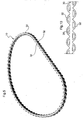
- An annuloplasty prosthesis comprises ( Figures 1 and 2) a member 10 of a shape generally reproducing the geometry of the annulus of a mitral valve, that is a closed ring-shape in the form of a D.
- the latter comprises an approximately straight intertrigonal portion 12, a first curved portion 14 opposite the straight portion and two second curved portions 16 having a more marked curvature than the first curved portion 14 connecting the latter to the extremities of the intertrigonal straight portion 12.
- Ring-shaped member 10 has three walls 18 having a sinusoidal profile of the same amplitude and period and offset longitudinally with respect to each other by one third of a period in such a way that they intersect.
- the intersections between walls 18 form a series of openings 20 which are orientated substantially transversely with respect to the general plane of the ring-shaped member 10.
- member 10 In transverse cross-section ( Figure 3), member 10 has substantially rectangular overall dimensions with a ratio between the height 22 and the width 24 which may preferably lie between 0.5 and 2.
- ring-shaped member 10 is coated with a sheath of biocompatible material, of which only a portion is illustrated in Figure 1 for the purposes of clarity, and this is identified by reference number 25.
- FIGS. 4 and 9 illustrate an alternative embodiment of the ring-shaped member in which the same numbers as are used in the preceding figures identify the same or equivalent parts.
- ring-shaped member 10 has a first and a second side wall 26 facing each other, which have a sinusoidal profile.
- the profiles of the two walls 26 match, having substantially the same amplitude and period and no longitudinal offset.
- the walls 26 are connected by interconnecting straight walls 28 at the points of flex.
- the member therefore has a number of openings 20 orientated substantially transversely with respect to the general plane of the ring-shaped member 10, which are separated from each other by the walls 28.
- Figures 5 and 10 illustrate a further alternative embodiment of the ring-shaped member in which the same numbers as are used in the preceding figures identify the same or equivalent parts.
- ring-shaped member 10 comprises a continuous inner wall 30 with an outer wall 32 on each side thereof formed from a series of adjacent convex portions, the convexity of which is directed outwards. In this way, two corresponding sets of openings 20 are formed, each of these having the shape of a circular segment.
- Figures 6 and 11 illustrate a further alternative embodiment of the ring-shaped member in which the same numbers as are used in the preceding figures identify the same or equivalent parts.
- ring-shaped member 10 has a plurality of openings 20 in correspondence of the intertrigonal portion 12 of the prosthesis and a respective opening 20 in correspondence of each curved portion 16 of more marked curvature, which connects one extremity of the intertrigonal straight portion 12 with the curved portion 14 of lesser curvature opposite to the straight portion 12.
- further openings 20 may be made in each curved portion 16.
- Figures 7 and 12 illustrate a further alternative embodiment of the ring-shaped member in which the same numbers as are used in the preceding figures identify the same or equivalent parts.
- ring-shaped member 10 has an opening 20 in the intertrigonal portion 12 of the prosthesis, a pair of openings 20 in each curved portion 16 of greater curvature and a further opening 20 in the curved portion 14 of lesser curvature.
- Figures 8 and 13 illustrate another alternative embodiment of the ring-shaped member in which the same numbers as are used in the preceding figures identify the same or equivalent parts.
- ring-shaped member 10 has a first and a second side wall 26 facing each other which bound between them a single opening 20 of annular shape.
- the distance between walls 26 is variable and in particular is a maximum in the intertrigonal portion 12 of the prosthesis, then decreases towards the curved portion 14 opposite to the intertrigonal portion 12 in such a way as to modulate its rigidity.
- the single opening 20 is filled with elastomer material 34 which also acts as a means for connecting walls 26.
- Elastomer material 34 may for example be silicone, polyurethane or mixtures thereof, as described in European patent application EP-A-1 266 641 by the same applicant.
- filler elastomer material 34 also performs the function of holding the walls together. It is however possible that such elastomer material is used to fill any of the openings in the annular member in the embodiments previously illustrated, essentially for the purpose of regulating the elastic properties of the prosthesis in an even more local manner.
- the size and spacing of the openings may remain constant over the entire extent of the ring-shaped member or may be varied so that the rigidity of the prosthesis can be controlled in a desired way depending upon the location and the direction of application of stresses.
Abstract
Description
- This invention relates in general to a device for heart valve repair surgery, in particular an annuloplasty prosthesis.
- A human heart has four heart valves: the mitral valve, the tricuspid valve, the pulmonary valve and the aortic valve.
- The mitral valve is located in the left atrio-ventricular opening and controls blood flow in a single direction from the atrium to the ventricle. It opens during diastole and closes again during systole, preventing blood from flowing back from the ventricle to the atrium. The annulus of a normally functioning mitral valve is characterised by shape, dimensions and flexibility such as to permit correct closure of the valve edges during the systolic stage. For example the mitral annulus has a characteristic "kidney" (or "D") shape, and is more flexible in the portion corresponding to the posterior lip of the valve. Diseases or genetic defects can cause deformation or expansion of the annulus of the mitral valve, giving rise to incomplete closure with the consequent regurgitation of blood.
- The same phenomenon may occur in the tricuspid valve, which is located between the right atrium and the right ventricle.
- A method which is frequently used to eliminate some pathological changes in mitral and tricuspid valves is that of restoring the valve annulus to its correct shape and size through surgical procedures known by the name of annuloplasty.
- Annuloplasty comprises surgically implanting a prosthesis supporting the expanded or deformed annulus in order to restore its dimensions and/or physiological shape in such a way as to allow the heart valve to function correctly.
- The support prostheses used in valve repair surgery take the name of annuloplasty prostheses. In most cases these prostheses comprise a closed or open ring structure comprising an internal element in the shape of a ring and an outer coating of biocompatible material which permits surgical suture.
- Various types of annuloplasty prostheses are described in the known art. In particular, prostheses whose rigidity can be rendered variable in a desired way depending upon the point, direction and/or manner in which stresses are applied are already known. For example patent application
EP-A-1 348 406 describes various embodiments of an annuloplasty prostheses comprising a laminar or tubular member having a plurality of openings in at least one portion thereof. - Typically, in order to shape a member of this kind into a ring, an operation in which a straight structure is shaped in order to confer the typical D shape upon it is first performed and then an operation to join the free ends, for example, by welding, is performed. Both these operations require that thermal and/or mechanical processes be carried out on an overall or local scale, and these can adversely affect the thermal/mechanical properties of the constituent material, which is usually an alloy, for example an alloy based on titanium, chromium-cobalt or nickel-titanium.
- The object of this invention is to provide an annuloplasty prosthesis in which the ring-shaped member can be constructed by a process which does not have the abovementioned disadvantages, while nevertheless having a geometry such as to confer the required mechanical characteristics upon it, in particular yielding to stresses which are exerted in its general plane which is greater than to stresses which are exerted in directions normal or oblique to that plane.
- According to the invention this object is achieved through an annuloplasty prosthesis comprising a ring-shaped member having substantially rectangular overall dimensions of the transverse cross-section with a ratio between height and width of between 0.2 and 10 and at least one through opening orientated substantially transversely to the general plane of the ring member.
- By "height" is meant the dimension normal to the general plane of the ring member, while by "width" is meant the dimension in the general plane of the ring member. The term "rectangular" also includes the special case in which the two dimensions in question are the same.
- Preferably, the ratio between the height and width of the overall dimensions of the transverse cross-section lies between 0.5 and 5.
- Advantageously, the ring-shaped member of the prosthesis according to the invention may be manufactured as a piece having a continuous structure directly from a flat sheet through the removal of material (for example by electroerosion or using machine tools), or through cutting (for example by laser). The annular continuity of the member is thus maintained through all the stages of processing, avoiding the performance of shaping and joining operations, such as welding, which could harm the thermal/mechanical properties of the constituent material. This material may for example be selected from alloys based on titanium or comprising titanium.
- The surface of the ring-shaped member may be coated with a sheath of biocompatible material selected for example from the group consisting of polymers, synthetic fabrics, biological tissues and combinations thereof. The surfaces of the ring-shaped member and/or the sheath may in turn be coated with blood-compatible carbon, for example turbostratic carbon. The process for providing a coating of this material is for example described in patents
US-5 084 151 ,US-5 387 247 ,US-5 370 684 ,US-5 133 845 andUS-5 423 886 by the same applicant. This coating helps to provide better blood compatibility for the prosthesis and controlled tissue growth of the recipient body. - Further features and advantages of this invention will be apparent from the following detailed description, which is provided by way of a non-restrictive example with reference to the appended drawings, in which:
- Figure 1 is a perspective view of a ring-shaped member of a prosthesis according to the invention,
- Figure 2 is a plan view of a portion of the member of Figure 1,
- Figure 3 is a view in cross-section along the line III-III in Figure 2,
- Figures 4 to 8 are perspective views of respective alternative embodiments of the ring-shaped member according to the invention,
- Figure 9 is a plan view of a portion of the member of Figure 4,
- Figure 10 is a plan view of a portion of the member of Figure 5,
- Figure 11 is a plan view of the member of Figure 6,
- Figure 12 is a plan view of the member of Figure 7, and
- Figure 13 is a plan view of the member of Figure 8.
- An annuloplasty prosthesis comprises (Figures 1 and 2) a
member 10 of a shape generally reproducing the geometry of the annulus of a mitral valve, that is a closed ring-shape in the form of a D. The latter comprises an approximately straightintertrigonal portion 12, a firstcurved portion 14 opposite the straight portion and two secondcurved portions 16 having a more marked curvature than the firstcurved portion 14 connecting the latter to the extremities of the intertrigonalstraight portion 12. - Ring-
shaped member 10 has threewalls 18 having a sinusoidal profile of the same amplitude and period and offset longitudinally with respect to each other by one third of a period in such a way that they intersect. The intersections betweenwalls 18 form a series ofopenings 20 which are orientated substantially transversely with respect to the general plane of the ring-shaped member 10. In embodiments of the invention not illustrated in the figures it is possible to provide a different number of intersecting walls having a sinusoidal profile which have amplitudes, periods and longitudinal offsets which can be freely selected independently of each other. - In transverse cross-section (Figure 3),
member 10 has substantially rectangular overall dimensions with a ratio between theheight 22 and thewidth 24 which may preferably lie between 0.5 and 2. - The surface of ring-
shaped member 10 is coated with a sheath of biocompatible material, of which only a portion is illustrated in Figure 1 for the purposes of clarity, and this is identified byreference number 25. - Figures 4 and 9 illustrate an alternative embodiment of the ring-shaped member in which the same numbers as are used in the preceding figures identify the same or equivalent parts.
- In this case ring-
shaped member 10 has a first and asecond side wall 26 facing each other, which have a sinusoidal profile. The profiles of the twowalls 26 match, having substantially the same amplitude and period and no longitudinal offset. In addition to this, thewalls 26 are connected by interconnectingstraight walls 28 at the points of flex. The member therefore has a number ofopenings 20 orientated substantially transversely with respect to the general plane of the ring-shaped member 10, which are separated from each other by thewalls 28. - Figures 5 and 10 illustrate a further alternative embodiment of the ring-shaped member in which the same numbers as are used in the preceding figures identify the same or equivalent parts.
- In this case ring-
shaped member 10 comprises a continuousinner wall 30 with anouter wall 32 on each side thereof formed from a series of adjacent convex portions, the convexity of which is directed outwards. In this way, two corresponding sets ofopenings 20 are formed, each of these having the shape of a circular segment. - Figures 6 and 11 illustrate a further alternative embodiment of the ring-shaped member in which the same numbers as are used in the preceding figures identify the same or equivalent parts.
- In this case ring-
shaped member 10 has a plurality ofopenings 20 in correspondence of theintertrigonal portion 12 of the prosthesis and arespective opening 20 in correspondence of eachcurved portion 16 of more marked curvature, which connects one extremity of the intertrigonalstraight portion 12 with thecurved portion 14 of lesser curvature opposite to thestraight portion 12. In a variant embodiment which is not illustrated in the figures,further openings 20 may be made in eachcurved portion 16. - Figures 7 and 12 illustrate a further alternative embodiment of the ring-shaped member in which the same numbers as are used in the preceding figures identify the same or equivalent parts.
- In this case ring-
shaped member 10 has anopening 20 in theintertrigonal portion 12 of the prosthesis, a pair ofopenings 20 in eachcurved portion 16 of greater curvature and afurther opening 20 in thecurved portion 14 of lesser curvature. - Figures 8 and 13 illustrate another alternative embodiment of the ring-shaped member in which the same numbers as are used in the preceding figures identify the same or equivalent parts.
- In this case ring-
shaped member 10 has a first and asecond side wall 26 facing each other which bound between them asingle opening 20 of annular shape. The distance betweenwalls 26 is variable and in particular is a maximum in theintertrigonal portion 12 of the prosthesis, then decreases towards thecurved portion 14 opposite to theintertrigonal portion 12 in such a way as to modulate its rigidity. - The
single opening 20 is filled withelastomer material 34 which also acts as a means for connectingwalls 26.Elastomer material 34 may for example be silicone, polyurethane or mixtures thereof, as described inEuropean patent application EP-A-1 266 641 by the same applicant. In this embodiment,filler elastomer material 34 also performs the function of holding the walls together. It is however possible that such elastomer material is used to fill any of the openings in the annular member in the embodiments previously illustrated, essentially for the purpose of regulating the elastic properties of the prosthesis in an even more local manner. - Of course, without altering the principle of the invention, details of construction and embodiments may be varied widely from what has been described purely by way of example without going beyond its scope as claimed. In particular the size and spacing of the openings may remain constant over the entire extent of the ring-shaped member or may be varied so that the rigidity of the prosthesis can be controlled in a desired way depending upon the location and the direction of application of stresses. Likewise, it is in principle possible to arrange the openings in an irregular way or in a pattern which repeats regularly.
Claims (24)
- Annuloplasty prosthesis comprising a ring-shaped member (10) having substantially rectangular overall dimensions of the transverse cross-section with a ratio between height (22) and width (24) of between 0.2 and 10 and at least one through opening (20) orientated substantially transversely to the general plane of the ring-shaped member (10).
- Prosthesis according to Claim 1, in which the said ratio between the height (22) and width (24) of the overall dimensions of the transverse cross-section lies between 0.5 and 5.
- Prosthesis according to any of the preceding claims, in which the said ring-shaped member (10) has a continuous structure without any joints.
- Prosthesis according to any of the preceding claims, in which the said ring-shaped member (10) has a plurality of openings (20) formed by the intersection of a plurality of longitudinally offset walls (18) having a sinusoidal profile.
- Prosthesis according to Claim 4, in which the said ring-shaped member (10) has a plurality of openings (20) formed by the intersection of three walls (18) having sinusoidal profiles of the same amplitude and period and longitudinally offset from each other by one third of a period.
- Prosthesis according to any of Claims 1 to 3, in which the said ring-shaped member (10) has a first and a second side wall (26) facing each other so as to bound the at least one opening (20) between them.
- Prosthesis according to Claim 6, in which the said first and second wall (26) are connected by interconnecting walls (28).
- Prosthesis according to Claim 7, in which the said first and second wall (26) have a matching sinusoidal profile and are connected by straight interconnecting walls (28) at the points of flex.
- Prosthesis according to any of Claims 1 to 3, in which the said ring-shaped member (10) comprises a continuous inner wall (30), on each of the two sides of which there is an outer wall (32) formed from a series of adjacent convex portions whose convexity faces outwards in such a way as to form a corresponding series of openings (20) each of which has the shape of a segment of a circle.
- Prosthesis according to any of Claims 1 to 3, in which the said ring-shaped member (10) has a plurality of openings (20) in correspondence of the intertrigonal portion (12) of the prosthesis and at least one respective opening (20) in correspondence of each curved portion (16) of greater curvature which connects one extremity of the intertrigonal straight portion (12) to the curved portion (14) of lesser curvature facing the straight portion (12).
- Prosthesis according to any of preceding Claims 1 to 3, in which the said ring-shaped member (10) has an opening (20) in correspondence of the intertrigonal portion (12) of the prosthesis, a pair of openings (20) in correspondence of each curved portion (16) of greater curvature, which connects one extremity of the intertrigonal straight portion (12) to the curved portion (14) of lesser curvature, and a further opening (20) in the curved portion (14) of lesser curvature.
- Prosthesis according to Claim 6, in which the said first and second side walls (26) bound between them a single opening (20) of annular shape which is filled with elastomer material (34) .
- Prosthesis according to Claim 12, in which the distance between the said first and second wall (26) is variable.
- Prosthesis according to Claim 13, in which the said distance is a maximum along the intertrigonal portion (12) of the prosthesis and decreases towards the curved portion (14) opposite the said intertrigonal portion (12).
- Prosthesis according to any of the preceding claims, in which the said ring-shaped member (in) is surrounded by a sheath (25) of a coating of biocompatible material.
- Prosthesis according to Claim 15, in which the said biocompatible material is selected from the group consisting of polymers, synthetic fabrics, biological tissues and combinations thereof.
- Prosthesis according to any of the preceding claims, in which at least one portion of the surface of the said member (10) and/or the said sheath (25) is coated with blood-compatible carbon.
- Prosthesis according to Claim 17, in which the said blood-compatible carbon is turbostratic carbon.
- Prosthesis according to any of the preceding claims, having a shape generally reproducing the geometry of the annulus of a heart valve.
- Prosthesis according to Claim 19, having a shape generally reproducing the geometry of the annulus of a mitral valve.
- Prosthesis according to Claim 19, having a shape generally reproducing the geometry of the annulus of a tricuspid valve.
- Process for the production of a prosthesis according to any of the preceding claims, in which the said ring-shaped member (10) is obtained from a flat sheet by removal of material or cutting, with the annular continuity of the member (10) being maintained during all stages of processing.
- Process according to Claim 22, in which the said removal of material is carried out by means of electroerosion or machine tools.
- Process according to Claim 22, in which the said cutting is performed by laser.
Priority Applications (3)
| Application Number | Priority Date | Filing Date | Title |
|---|---|---|---|
| EP05425303A EP1719476B1 (en) | 2005-05-06 | 2005-05-06 | Annuloplasty prosthesis |
| ES05425303T ES2376885T3 (en) | 2005-05-06 | 2005-05-06 | Annuloplasty prosthesis |
| AT05425303T ATE534346T1 (en) | 2005-05-06 | 2005-05-06 | ANNULOPLASTY PROSTHESIS |
Applications Claiming Priority (1)
| Application Number | Priority Date | Filing Date | Title |
|---|---|---|---|
| EP05425303A EP1719476B1 (en) | 2005-05-06 | 2005-05-06 | Annuloplasty prosthesis |
Publications (2)
| Publication Number | Publication Date |
|---|---|
| EP1719476A1 true EP1719476A1 (en) | 2006-11-08 |
| EP1719476B1 EP1719476B1 (en) | 2011-11-23 |
Family
ID=34943188
Family Applications (1)
| Application Number | Title | Priority Date | Filing Date |
|---|---|---|---|
| EP05425303A Active EP1719476B1 (en) | 2005-05-06 | 2005-05-06 | Annuloplasty prosthesis |
Country Status (3)
| Country | Link |
|---|---|
| EP (1) | EP1719476B1 (en) |
| AT (1) | ATE534346T1 (en) |
| ES (1) | ES2376885T3 (en) |
Cited By (4)
| Publication number | Priority date | Publication date | Assignee | Title |
|---|---|---|---|---|
| WO2010070455A1 (en) * | 2008-12-15 | 2010-06-24 | Jean-Paul Couetil | Annuloplasty ring with directional flexibilities and rigidities to assist the mitral annulus dynamics |
| EP2257241A1 (en) * | 2008-03-13 | 2010-12-08 | Sciencity Co., Ltd. | An apparatus for mitral lifting annuloplaty |
| CN109662805A (en) * | 2019-01-18 | 2019-04-23 | 西安增材制造国家研究院有限公司 | A kind of Tricusp Valvuloplasty ring and its manufacturing method |
| US11826249B2 (en) | 2011-10-19 | 2023-11-28 | Twelve, Inc. | Devices, systems and methods for heart valve replacement |
Families Citing this family (23)
| Publication number | Priority date | Publication date | Assignee | Title |
|---|---|---|---|---|
| US8579964B2 (en) | 2010-05-05 | 2013-11-12 | Neovasc Inc. | Transcatheter mitral valve prosthesis |
| US9554897B2 (en) | 2011-04-28 | 2017-01-31 | Neovasc Tiara Inc. | Methods and apparatus for engaging a valve prosthesis with tissue |
| US9308087B2 (en) | 2011-04-28 | 2016-04-12 | Neovasc Tiara Inc. | Sequentially deployed transcatheter mitral valve prosthesis |
| AU2012272855C1 (en) | 2011-06-21 | 2018-04-05 | Twelve, Inc. | Prosthetic heart valve devices and associated systems and methods |
| US11202704B2 (en) | 2011-10-19 | 2021-12-21 | Twelve, Inc. | Prosthetic heart valve devices, prosthetic mitral valves and associated systems and methods |
| US9039757B2 (en) | 2011-10-19 | 2015-05-26 | Twelve, Inc. | Prosthetic heart valve devices, prosthetic mitral valves and associated systems and methods |
| US10016271B2 (en) | 2011-10-19 | 2018-07-10 | Twelve, Inc. | Prosthetic heart valve devices, prosthetic mitral valves and associated systems and methods |
| US9345573B2 (en) | 2012-05-30 | 2016-05-24 | Neovasc Tiara Inc. | Methods and apparatus for loading a prosthesis onto a delivery system |
| US9572665B2 (en) | 2013-04-04 | 2017-02-21 | Neovasc Tiara Inc. | Methods and apparatus for delivering a prosthetic valve to a beating heart |
| GB2539444A (en) | 2015-06-16 | 2016-12-21 | Ucl Business Plc | Prosthetic heart valve |
| CN108882981B (en) | 2016-01-29 | 2021-08-10 | 内奥瓦斯克迪亚拉公司 | Prosthetic valve for preventing outflow obstruction |
| EP3541462A4 (en) | 2016-11-21 | 2020-06-17 | Neovasc Tiara Inc. | Methods and systems for rapid retraction of a transcatheter heart valve delivery system |
| US10702378B2 (en) | 2017-04-18 | 2020-07-07 | Twelve, Inc. | Prosthetic heart valve device and associated systems and methods |
| US10709591B2 (en) | 2017-06-06 | 2020-07-14 | Twelve, Inc. | Crimping device and method for loading stents and prosthetic heart valves |
| US10729541B2 (en) | 2017-07-06 | 2020-08-04 | Twelve, Inc. | Prosthetic heart valve devices and associated systems and methods |
| US10786352B2 (en) | 2017-07-06 | 2020-09-29 | Twelve, Inc. | Prosthetic heart valve devices and associated systems and methods |
| EP3672530A4 (en) | 2017-08-25 | 2021-04-14 | Neovasc Tiara Inc. | Sequentially deployed transcatheter mitral valve prosthesis |
| JP7260930B2 (en) | 2018-11-08 | 2023-04-19 | ニオバスク ティアラ インコーポレイテッド | Ventricular deployment of a transcatheter mitral valve prosthesis |
| EP3946163A4 (en) | 2019-04-01 | 2022-12-21 | Neovasc Tiara Inc. | Controllably deployable prosthetic valve |
| CN113924065A (en) | 2019-04-10 | 2022-01-11 | 内奥瓦斯克迪亚拉公司 | Prosthetic valve with natural blood flow |
| US11452599B2 (en) | 2019-05-02 | 2022-09-27 | Twelve, Inc. | Fluid diversion devices for hydraulic delivery systems and associated methods |
| EP3972673A4 (en) | 2019-05-20 | 2023-06-07 | Neovasc Tiara Inc. | Introducer with hemostasis mechanism |
| WO2020257643A1 (en) | 2019-06-20 | 2020-12-24 | Neovasc Tiara Inc. | Low profile prosthetic mitral valve |
Citations (6)
| Publication number | Priority date | Publication date | Assignee | Title |
|---|---|---|---|---|
| SU577022A1 (en) * | 1976-06-25 | 1977-10-30 | Всесоюзный Научно-Исследовательский Институт Клинической И Экспериментальной Хирургии | Cardiac valve prosthesis |
| US5961539A (en) * | 1997-01-17 | 1999-10-05 | Segmed, Inc. | Method and apparatus for sizing, stabilizing and/or reducing the circumference of an anatomical structure |
| US6102945A (en) | 1998-10-16 | 2000-08-15 | Sulzer Carbomedics, Inc. | Separable annuloplasty ring |
| US6368348B1 (en) * | 2000-05-15 | 2002-04-09 | Shlomo Gabbay | Annuloplasty prosthesis for supporting an annulus of a heart valve |
| EP1348406A1 (en) * | 2002-03-27 | 2003-10-01 | SORIN BIOMEDICA CARDIO S.p.A. | A prosthesis for annuloplasty comprising a perforated element |
| WO2005007037A1 (en) * | 2003-07-11 | 2005-01-27 | Vedic Biotechnology, Inc. | Selective annuloplasty for atrio-ventricular heart valve regurgitation and devices therefor |
-
2005
- 2005-05-06 AT AT05425303T patent/ATE534346T1/en active
- 2005-05-06 EP EP05425303A patent/EP1719476B1/en active Active
- 2005-05-06 ES ES05425303T patent/ES2376885T3/en active Active
Patent Citations (6)
| Publication number | Priority date | Publication date | Assignee | Title |
|---|---|---|---|---|
| SU577022A1 (en) * | 1976-06-25 | 1977-10-30 | Всесоюзный Научно-Исследовательский Институт Клинической И Экспериментальной Хирургии | Cardiac valve prosthesis |
| US5961539A (en) * | 1997-01-17 | 1999-10-05 | Segmed, Inc. | Method and apparatus for sizing, stabilizing and/or reducing the circumference of an anatomical structure |
| US6102945A (en) | 1998-10-16 | 2000-08-15 | Sulzer Carbomedics, Inc. | Separable annuloplasty ring |
| US6368348B1 (en) * | 2000-05-15 | 2002-04-09 | Shlomo Gabbay | Annuloplasty prosthesis for supporting an annulus of a heart valve |
| EP1348406A1 (en) * | 2002-03-27 | 2003-10-01 | SORIN BIOMEDICA CARDIO S.p.A. | A prosthesis for annuloplasty comprising a perforated element |
| WO2005007037A1 (en) * | 2003-07-11 | 2005-01-27 | Vedic Biotechnology, Inc. | Selective annuloplasty for atrio-ventricular heart valve regurgitation and devices therefor |
Cited By (6)
| Publication number | Priority date | Publication date | Assignee | Title |
|---|---|---|---|---|
| EP2257241A1 (en) * | 2008-03-13 | 2010-12-08 | Sciencity Co., Ltd. | An apparatus for mitral lifting annuloplaty |
| EP2257241A4 (en) * | 2008-03-13 | 2013-01-09 | Sciencity Co Ltd | An apparatus for mitral lifting annuloplaty |
| WO2010070455A1 (en) * | 2008-12-15 | 2010-06-24 | Jean-Paul Couetil | Annuloplasty ring with directional flexibilities and rigidities to assist the mitral annulus dynamics |
| US11826249B2 (en) | 2011-10-19 | 2023-11-28 | Twelve, Inc. | Devices, systems and methods for heart valve replacement |
| CN109662805A (en) * | 2019-01-18 | 2019-04-23 | 西安增材制造国家研究院有限公司 | A kind of Tricusp Valvuloplasty ring and its manufacturing method |
| CN109662805B (en) * | 2019-01-18 | 2024-02-13 | 西安增材制造国家研究院有限公司 | Tricuspid annuloplasty ring and method of making same |
Also Published As
| Publication number | Publication date |
|---|---|
| EP1719476B1 (en) | 2011-11-23 |
| ATE534346T1 (en) | 2011-12-15 |
| ES2376885T3 (en) | 2012-03-20 |
Similar Documents
| Publication | Publication Date | Title |
|---|---|---|
| EP1719476B1 (en) | Annuloplasty prosthesis | |
| EP1803420B1 (en) | Annuloplasty prosthesis with an auxetic structure | |
| EP3435919B1 (en) | A prosthetic device for mitral valve repair | |
| EP2153799B1 (en) | A prosthesis for annuloplasty comprising a perforated element | |
| EP0532678B1 (en) | Mitral heart valve replacements | |
| EP1865889B1 (en) | Connecting band and stress absorbing frame for highly flexible heart valve | |
| JP4287272B2 (en) | Polymeric valve membrane structure for medical devices | |
| US20050075727A1 (en) | Mitral valve prosthesis | |
| JP5881653B2 (en) | Intra-annular mounting frame for aortic valve repair | |
| US5776189A (en) | Cardiac valvular support prosthesis | |
| WO1991019465A2 (en) | Mitral heart valve replacements | |
| KR20020064878A (en) | Mitral valve annuloplasty ring and method | |
| WO2001041679A1 (en) | Hearth valve prosthesis and method of manufacture | |
| EP0860151A1 (en) | Cardiac valvular support prosthesis | |
| JP2009506853A (en) | Valve molds and prostheses for mammalian systems | |
| US11554015B2 (en) | Minimally-invasive low strain annuloplasty ring | |
| US20110071622A1 (en) | Instrument for the surgical treatment of aortic valve defects | |
| EP3852681A1 (en) | A medical device for improving function of a heart valve | |
| MXPA02002942A (en) | Mitral valve annuloplasty ring and method |
Legal Events
| Date | Code | Title | Description |
|---|---|---|---|
| PUAI | Public reference made under article 153(3) epc to a published international application that has entered the european phase |
Free format text: ORIGINAL CODE: 0009012 |
|
| AK | Designated contracting states |
Kind code of ref document: A1 Designated state(s): AT BE BG CH CY CZ DE DK EE ES FI FR GB GR HU IE IS IT LI LT LU MC NL PL PT RO SE SI SK TR |
|
| AX | Request for extension of the european patent |
Extension state: AL BA HR LV MK YU |
|
| 17P | Request for examination filed |
Effective date: 20070507 |
|
| AKX | Designation fees paid |
Designated state(s): AT BE BG CH CY CZ DE DK EE ES FI FR GB GR HU IE IS IT LI LT LU MC NL PL PT RO SE SI SK TR |
|
| 17Q | First examination report despatched |
Effective date: 20070625 |
|
| GRAP | Despatch of communication of intention to grant a patent |
Free format text: ORIGINAL CODE: EPIDOSNIGR1 |
|
| GRAS | Grant fee paid |
Free format text: ORIGINAL CODE: EPIDOSNIGR3 |
|
| RIN1 | Information on inventor provided before grant (corrected) |
Inventor name: BERGAMASCO, GIOVANNI Inventor name: BURRIESCI, GAETANO Inventor name: STACCHINO, CARLA |
|
| GRAA | (expected) grant |
Free format text: ORIGINAL CODE: 0009210 |
|
| AK | Designated contracting states |
Kind code of ref document: B1 Designated state(s): AT BE BG CH CY CZ DE DK EE ES FI FR GB GR HU IE IS IT LI LT LU MC NL PL PT RO SE SI SK TR |
|
| REG | Reference to a national code |
Ref country code: GB Ref legal event code: FG4D |
|
| REG | Reference to a national code |
Ref country code: CH Ref legal event code: EP |
|
| REG | Reference to a national code |
Ref country code: IE Ref legal event code: FG4D |
|
| REG | Reference to a national code |
Ref country code: DE Ref legal event code: R096 Ref document number: 602005031325 Country of ref document: DE Effective date: 20120126 |
|
| REG | Reference to a national code |
Ref country code: NL Ref legal event code: VDEP Effective date: 20111123 |
|
| REG | Reference to a national code |
Ref country code: ES Ref legal event code: FG2A Ref document number: 2376885 Country of ref document: ES Kind code of ref document: T3 Effective date: 20120320 |
|
| LTIE | Lt: invalidation of european patent or patent extension |
Effective date: 20111123 |
|
| PG25 | Lapsed in a contracting state [announced via postgrant information from national office to epo] |
Ref country code: LT Free format text: LAPSE BECAUSE OF FAILURE TO SUBMIT A TRANSLATION OF THE DESCRIPTION OR TO PAY THE FEE WITHIN THE PRESCRIBED TIME-LIMIT Effective date: 20111123 Ref country code: IS Free format text: LAPSE BECAUSE OF FAILURE TO SUBMIT A TRANSLATION OF THE DESCRIPTION OR TO PAY THE FEE WITHIN THE PRESCRIBED TIME-LIMIT Effective date: 20120323 |
|
| PG25 | Lapsed in a contracting state [announced via postgrant information from national office to epo] |
Ref country code: PT Free format text: LAPSE BECAUSE OF FAILURE TO SUBMIT A TRANSLATION OF THE DESCRIPTION OR TO PAY THE FEE WITHIN THE PRESCRIBED TIME-LIMIT Effective date: 20120323 Ref country code: SI Free format text: LAPSE BECAUSE OF FAILURE TO SUBMIT A TRANSLATION OF THE DESCRIPTION OR TO PAY THE FEE WITHIN THE PRESCRIBED TIME-LIMIT Effective date: 20111123 Ref country code: SE Free format text: LAPSE BECAUSE OF FAILURE TO SUBMIT A TRANSLATION OF THE DESCRIPTION OR TO PAY THE FEE WITHIN THE PRESCRIBED TIME-LIMIT Effective date: 20111123 Ref country code: BE Free format text: LAPSE BECAUSE OF FAILURE TO SUBMIT A TRANSLATION OF THE DESCRIPTION OR TO PAY THE FEE WITHIN THE PRESCRIBED TIME-LIMIT Effective date: 20111123 Ref country code: GR Free format text: LAPSE BECAUSE OF FAILURE TO SUBMIT A TRANSLATION OF THE DESCRIPTION OR TO PAY THE FEE WITHIN THE PRESCRIBED TIME-LIMIT Effective date: 20120224 Ref country code: NL Free format text: LAPSE BECAUSE OF FAILURE TO SUBMIT A TRANSLATION OF THE DESCRIPTION OR TO PAY THE FEE WITHIN THE PRESCRIBED TIME-LIMIT Effective date: 20111123 |
|
| PG25 | Lapsed in a contracting state [announced via postgrant information from national office to epo] |
Ref country code: CY Free format text: LAPSE BECAUSE OF FAILURE TO SUBMIT A TRANSLATION OF THE DESCRIPTION OR TO PAY THE FEE WITHIN THE PRESCRIBED TIME-LIMIT Effective date: 20111123 |
|
| PG25 | Lapsed in a contracting state [announced via postgrant information from national office to epo] |
Ref country code: DK Free format text: LAPSE BECAUSE OF FAILURE TO SUBMIT A TRANSLATION OF THE DESCRIPTION OR TO PAY THE FEE WITHIN THE PRESCRIBED TIME-LIMIT Effective date: 20111123 Ref country code: CZ Free format text: LAPSE BECAUSE OF FAILURE TO SUBMIT A TRANSLATION OF THE DESCRIPTION OR TO PAY THE FEE WITHIN THE PRESCRIBED TIME-LIMIT Effective date: 20111123 Ref country code: SK Free format text: LAPSE BECAUSE OF FAILURE TO SUBMIT A TRANSLATION OF THE DESCRIPTION OR TO PAY THE FEE WITHIN THE PRESCRIBED TIME-LIMIT Effective date: 20111123 Ref country code: EE Free format text: LAPSE BECAUSE OF FAILURE TO SUBMIT A TRANSLATION OF THE DESCRIPTION OR TO PAY THE FEE WITHIN THE PRESCRIBED TIME-LIMIT Effective date: 20111123 Ref country code: BG Free format text: LAPSE BECAUSE OF FAILURE TO SUBMIT A TRANSLATION OF THE DESCRIPTION OR TO PAY THE FEE WITHIN THE PRESCRIBED TIME-LIMIT Effective date: 20120223 |
|
| PG25 | Lapsed in a contracting state [announced via postgrant information from national office to epo] |
Ref country code: PL Free format text: LAPSE BECAUSE OF FAILURE TO SUBMIT A TRANSLATION OF THE DESCRIPTION OR TO PAY THE FEE WITHIN THE PRESCRIBED TIME-LIMIT Effective date: 20111123 Ref country code: RO Free format text: LAPSE BECAUSE OF FAILURE TO SUBMIT A TRANSLATION OF THE DESCRIPTION OR TO PAY THE FEE WITHIN THE PRESCRIBED TIME-LIMIT Effective date: 20111123 |
|
| REG | Reference to a national code |
Ref country code: AT Ref legal event code: MK05 Ref document number: 534346 Country of ref document: AT Kind code of ref document: T Effective date: 20111123 |
|
| PLBE | No opposition filed within time limit |
Free format text: ORIGINAL CODE: 0009261 |
|
| STAA | Information on the status of an ep patent application or granted ep patent |
Free format text: STATUS: NO OPPOSITION FILED WITHIN TIME LIMIT |
|
| 26N | No opposition filed |
Effective date: 20120824 |
|
| REG | Reference to a national code |
Ref country code: DE Ref legal event code: R097 Ref document number: 602005031325 Country of ref document: DE Effective date: 20120824 |
|
| PG25 | Lapsed in a contracting state [announced via postgrant information from national office to epo] |
Ref country code: MC Free format text: LAPSE BECAUSE OF NON-PAYMENT OF DUE FEES Effective date: 20120531 |
|
| REG | Reference to a national code |
Ref country code: CH Ref legal event code: PL |
|
| PG25 | Lapsed in a contracting state [announced via postgrant information from national office to epo] |
Ref country code: CH Free format text: LAPSE BECAUSE OF NON-PAYMENT OF DUE FEES Effective date: 20120531 Ref country code: AT Free format text: LAPSE BECAUSE OF FAILURE TO SUBMIT A TRANSLATION OF THE DESCRIPTION OR TO PAY THE FEE WITHIN THE PRESCRIBED TIME-LIMIT Effective date: 20111123 Ref country code: LI Free format text: LAPSE BECAUSE OF NON-PAYMENT OF DUE FEES Effective date: 20120531 |
|
| REG | Reference to a national code |
Ref country code: IE Ref legal event code: MM4A |
|
| PG25 | Lapsed in a contracting state [announced via postgrant information from national office to epo] |
Ref country code: IE Free format text: LAPSE BECAUSE OF NON-PAYMENT OF DUE FEES Effective date: 20120506 |
|
| PG25 | Lapsed in a contracting state [announced via postgrant information from national office to epo] |
Ref country code: FI Free format text: LAPSE BECAUSE OF FAILURE TO SUBMIT A TRANSLATION OF THE DESCRIPTION OR TO PAY THE FEE WITHIN THE PRESCRIBED TIME-LIMIT Effective date: 20111123 |
|
| PG25 | Lapsed in a contracting state [announced via postgrant information from national office to epo] |
Ref country code: TR Free format text: LAPSE BECAUSE OF FAILURE TO SUBMIT A TRANSLATION OF THE DESCRIPTION OR TO PAY THE FEE WITHIN THE PRESCRIBED TIME-LIMIT Effective date: 20111123 |
|
| PG25 | Lapsed in a contracting state [announced via postgrant information from national office to epo] |
Ref country code: LU Free format text: LAPSE BECAUSE OF NON-PAYMENT OF DUE FEES Effective date: 20120506 |
|
| PG25 | Lapsed in a contracting state [announced via postgrant information from national office to epo] |
Ref country code: HU Free format text: LAPSE BECAUSE OF FAILURE TO SUBMIT A TRANSLATION OF THE DESCRIPTION OR TO PAY THE FEE WITHIN THE PRESCRIBED TIME-LIMIT Effective date: 20050506 |
|
| REG | Reference to a national code |
Ref country code: FR Ref legal event code: PLFP Year of fee payment: 12 |
|
| REG | Reference to a national code |
Ref country code: FR Ref legal event code: PLFP Year of fee payment: 13 |
|
| REG | Reference to a national code |
Ref country code: FR Ref legal event code: PLFP Year of fee payment: 14 |
|
| REG | Reference to a national code |
Ref country code: DE Ref legal event code: R081 Ref document number: 602005031325 Country of ref document: DE Owner name: CORCYM S.R.L., IT Free format text: FORMER OWNER: SORIN BIOMEDICA CARDIO S.R.L., SALUGGIA, VERCELLI, IT Ref country code: DE Ref legal event code: R082 Ref document number: 602005031325 Country of ref document: DE Representative=s name: PAUL & ALBRECHT PATENTANWAELTE PARTG MBB, DE Ref country code: DE Ref legal event code: R081 Ref document number: 602005031325 Country of ref document: DE Owner name: SORIN GROUP ITALIA S.R.L., IT Free format text: FORMER OWNER: SORIN BIOMEDICA CARDIO S.R.L., SALUGGIA, VERCELLI, IT |
|
| REG | Reference to a national code |
Ref country code: GB Ref legal event code: 732E Free format text: REGISTERED BETWEEN 20210318 AND 20210324 |
|
| REG | Reference to a national code |
Ref country code: ES Ref legal event code: PC2A Owner name: SORIN GROUP ITALIA S.R.L. Effective date: 20210531 |
|
| REG | Reference to a national code |
Ref country code: DE Ref legal event code: R081 Ref document number: 602005031325 Country of ref document: DE Owner name: CORCYM S.R.L., IT Free format text: FORMER OWNER: SORIN GROUP ITALIA S.R.L., SALUGGIA, IT |
|
| REG | Reference to a national code |
Ref country code: GB Ref legal event code: 732E Free format text: REGISTERED BETWEEN 20220210 AND 20220216 |
|
| REG | Reference to a national code |
Ref country code: ES Ref legal event code: PC2A Owner name: CORCYM S.R.L Effective date: 20220523 |
|
| REG | Reference to a national code |
Ref country code: GB Ref legal event code: 732E Free format text: REGISTERED BETWEEN 20221110 AND 20221116 |
|
| P01 | Opt-out of the competence of the unified patent court (upc) registered |
Effective date: 20230530 |
|
| PGFP | Annual fee paid to national office [announced via postgrant information from national office to epo] |
Ref country code: IT Payment date: 20230519 Year of fee payment: 19 Ref country code: FR Payment date: 20230530 Year of fee payment: 19 Ref country code: ES Payment date: 20230612 Year of fee payment: 19 Ref country code: DE Payment date: 20230519 Year of fee payment: 19 |
|
| PGFP | Annual fee paid to national office [announced via postgrant information from national office to epo] |
Ref country code: GB Payment date: 20230518 Year of fee payment: 19 |