EP1722065A1 - Panel of hollow reinforcement beams - Google Patents
Panel of hollow reinforcement beams Download PDFInfo
- Publication number
- EP1722065A1 EP1722065A1 EP05290991A EP05290991A EP1722065A1 EP 1722065 A1 EP1722065 A1 EP 1722065A1 EP 05290991 A EP05290991 A EP 05290991A EP 05290991 A EP05290991 A EP 05290991A EP 1722065 A1 EP1722065 A1 EP 1722065A1
- Authority
- EP
- European Patent Office
- Prior art keywords
- longitudinal
- panel
- hollow
- leaf
- portions
- Prior art date
- Legal status (The legal status is an assumption and is not a legal conclusion. Google has not performed a legal analysis and makes no representation as to the accuracy of the status listed.)
- Withdrawn
Links
Images


Classifications
-
- E—FIXED CONSTRUCTIONS
- E06—DOORS, WINDOWS, SHUTTERS, OR ROLLER BLINDS IN GENERAL; LADDERS
- E06B—FIXED OR MOVABLE CLOSURES FOR OPENINGS IN BUILDINGS, VEHICLES, FENCES OR LIKE ENCLOSURES IN GENERAL, e.g. DOORS, WINDOWS, BLINDS, GATES
- E06B3/00—Window sashes, door leaves, or like elements for closing wall or like openings; Layout of fixed or moving closures, e.g. windows in wall or like openings; Features of rigidly-mounted outer frames relating to the mounting of wing frames
- E06B3/32—Arrangements of wings characterised by the manner of movement; Arrangements of movable wings in openings; Features of wings or frames relating solely to the manner of movement of the wing
- E06B3/48—Wings connected at their edges, e.g. foldable wings
- E06B3/485—Sectional doors
-
- E—FIXED CONSTRUCTIONS
- E06—DOORS, WINDOWS, SHUTTERS, OR ROLLER BLINDS IN GENERAL; LADDERS
- E06B—FIXED OR MOVABLE CLOSURES FOR OPENINGS IN BUILDINGS, VEHICLES, FENCES OR LIKE ENCLOSURES IN GENERAL, e.g. DOORS, WINDOWS, BLINDS, GATES
- E06B3/00—Window sashes, door leaves, or like elements for closing wall or like openings; Layout of fixed or moving closures, e.g. windows in wall or like openings; Features of rigidly-mounted outer frames relating to the mounting of wing frames
- E06B3/70—Door leaves
- E06B2003/7049—Specific panel characteristics
- E06B2003/7053—Specific panel characteristics corrugated
-
- E—FIXED CONSTRUCTIONS
- E06—DOORS, WINDOWS, SHUTTERS, OR ROLLER BLINDS IN GENERAL; LADDERS
- E06B—FIXED OR MOVABLE CLOSURES FOR OPENINGS IN BUILDINGS, VEHICLES, FENCES OR LIKE ENCLOSURES IN GENERAL, e.g. DOORS, WINDOWS, BLINDS, GATES
- E06B3/00—Window sashes, door leaves, or like elements for closing wall or like openings; Layout of fixed or moving closures, e.g. windows in wall or like openings; Features of rigidly-mounted outer frames relating to the mounting of wing frames
- E06B3/70—Door leaves
- E06B3/72—Door leaves consisting of frame and panels, e.g. of raised panel type
- E06B3/723—Door leaves consisting of frame and panels, e.g. of raised panel type at least one side of the frame consisting solely of a bent panel edge
Definitions
- the invention relates to a panel specifically designed for the realization with other similar panels of a garage door leaf, such a leaf and such a garage door, and finally a method of manufacturing such a panel.
- panels for a garage door leaf are made from a single steel plate.
- the document DE-A-42 27 311 relates to a panel of this type formed of a single wall comprising a main portion ribbed in the longitudinal direction and on the longitudinal edges extending parallel to the ribs, two portions shaped by hollow hollow beam-shaped folding. Two such adjacent hollow box-shaped portions belonging to two adjacent panels are spaced from each other by a recessed space visible towards the outside (front) of the leaf. On the right side of this space, and on the inside (rear) side, is the articulation hinge of the two panels.
- a sealing block carried by the lower hollow box-shaped portion of the upper panel, the latter comprising a vertical blocking rib directed downwards and to the rear of which is the sealing block having a profiled form of pseudo-triangle curvilinear.
- a curved rib carried by the hollow box-shaped upper part of the lower panel, the curved rib being generally directed upwards.
- Such an embodiment has the disadvantages, in particular, that there is a hollow space between the two adjacent hollow box-shaped portions of two neighboring panels, clearly visible from the outside of the leaf.
- This hollow space is particularly unsightly, while the aesthetics of garage doors is a requirement increasingly sought by customers.
- This recessed space whose transverse cross-sectional profile is substantially C or U coated, does not allow a convenient evacuation of water in case of rain or cleaning, in addition to dust and debris accumulates there.
- the seal can not be perfectly satisfied, being obtained by sliding contact of the curved rib on the rear face. curved sealing block. Finally, the function anti-finger pliers is not assured.
- the object of the invention is to solve these problems.
- the invention relates to a panel for producing a leaf of a sectional garage door, said panel consisting of a metal wall defining a broad central longitudinal band, generally flat , forming the main part of the panel and extending along its entire length L between two lateral edges and, on either side of the central strip, first and second upper and lower longitudinal portions respectively in the form of a hollow beam obtained by folding or profiling the two longitudinal end portions of the metal wall on itself, each having a generally pseudo-trapezoidal profiled shape with a wing fixed by bonding to the strip towards the inside of the panel.
- the upper longitudinal portion in the form of a hollow beam has a small base, a large base, a portion substantially perpendicular or slightly inclined with respect to the bases and which is adjacent to the gluing attachment wing and a portion inclined relative to the bases of an angle ⁇ , ⁇ .
- the lower hollow-beam longitudinal portion has a small base, a large base, a substantially perpendicular or slightly inclined portion with respect to the bases and of which the gluing attachment wing is adjoined and a portion inclined relative to the bases of an angle ⁇ , ⁇ .
- the upper longitudinal portion in the form of hollow beam comprises a second portion, extending the central strip being inclined relative to the plane thereof by an angle ⁇ and a third portion, extending the second portion by being inclined relative to the plane of the central strip by an angle ⁇ greater than ⁇ , the two portions making a salient angle.
- the hollow-beam-shaped lower longitudinal portion comprises a second portion, extending the central strip being inclined relative to the plane thereof by an angle ⁇ and a third portion, extending the second portion while being inclined to the plane of the central band of an angle ⁇ greater than ⁇ , the two portions forming a reentrant angle.
- the angle ⁇ is substantially equal to ⁇ , respectively the angle ⁇ substantially equal to ⁇ ;
- the angle ⁇ , ⁇ is between 10 ° and 30 °, the angle ⁇ , ⁇ is between 40 ° and 50 °;
- the metal wall is substantially flat and has a thickness of between 0.2 and 0.9 mm, in particular of the order of 0.5 mm;
- the transverse width l5, l6 of the longitudinal hollow-beam-shaped parts is of the order of 5% to 20% of the total width l1 of the panel;
- the distance h is between 15 and 45 mm, in particular of the order of 20 mm.
- the main part of the panel comprises at least one stiffening means comprising a cassette or a fold made in the wall, said fold extending substantially parallel to the two longitudinal hollow beam-shaped parts.
- the panel comprises at least one reinforcement element attached and fixed on the inner face of the main wall substantially perpendicular to the two longitudinal hollow beam-shaped parts.
- a vertical reinforcement of metal, comprises a flat rectangular wall of which substantially perpendicularly project two substantially identical lateral walls, having a succession of teeth and crenellations, the teeth of a side wall being folded towards the opposite side wall so to be substantially parallel to the plane wall, the reinforcing elements being fixed by gluing the teeth against the face located towards the inside of the central strip.
- the invention relates to a door leaf for closing an opening of a construction and can be guided between a closed position in which the leaf is substantially vertical, and an open position in which it is substantially horizontal, said leaf comprising a plurality of panels as just described, two panels adjacent members being associated with one another in the vicinity of the hollow-beam upper longitudinal portion of the lower panel and the lower hollow-beam longitudinal portion of the adjacent upper panel by hinge means.
- the invention relates to a door intended to be fixed to a construction in an opening of said construction, which door comprises a leaf as described and means for guiding said leaf between the closed position and the open position.
- a door comprises means for balancing the leaf (38) in the form of a system of shafts and springs.
- the invention relates to a method of manufacturing a panel as described above, in which the wall is shaped by producing, in an extreme longitudinal portion along a longitudinal edge of the wall, a series of lines. bending parallel to each other and parallel to said edge, so as to form the two respectively upper and lower longitudinal portions in the form of hollow beam and is secured by gluing on the one hand the wing of the upper longitudinal portion shaped hollow beam and on the other hand the wing of the lower longitudinal portion in the form of a hollow beam at said central strip.
- the shaping of the wall is carried out by folding or profiling by means of rollers cooperating with the wall, said wall being displaced substantially parallel to said edge during the profiling.
- a panel 1 is formed from a substantially rectangular metal wall, for example a sheet metal plate 50 having a thickness of between 0.2 and 0.9 mm, and in particular of the order of 0.5 mm.
- a panel 1 is intended for the manufacture of a sectional door 37, typically of garage, comprising a leaf 38 made from a plurality of panels 1 associated with each other.
- the door 37 also includes a frame 39, intended to be fixed to the structure of a construction around an opening.
- This frame 39 comprises two vertical uprights 40, 41 and a substantially horizontal upper cross 42.
- first direction D1 substantially vertical
- second direction D2 substantially parallel to the cross member 42
- third direction D3 forming with D1 and D2 an orthogonal reference.
- the door 37 is also provided with two lateral guiding rails 43.
- Each guiding rail 43 forms an angle and comprises a first part fixed on an upright 40, 41 and a second part 44, 45 extending in the direction D3 from the upper rail 42.
- the door 37 further comprises a rear crossmember 46, parallel to the upper cross member 43, connecting the ends of the second portions 44, 45 of the rails 43 not connected to the uprights 40, 41.
- the second portions 44, 45 of the rails 43 and the rear crossmember 46 are intended to be fixed to the ceiling inside I of the construction.
- Guiding means cooperate with the lateral rails 43, so that the leaf 38 can be moved between a closed end position, in which leaf 38, substantially plane and vertical, closes opening of the construction, and an open end position, wherein the leaf 38, substantially flat and horizontal, is located under the ceiling of the construction, inside I thereof.
- the balancing of the leaf 38 of the door 37 is achieved by a system of shafts and springs
- the leaf 38 comprises a plurality (for example six in a typical embodiment) of similar panels 1 associated with each other by means of hinges 33, these panels 1 extending parallel to D2 over the entire length - horizontal - of the leaf 38.
- the panel 1 is substantially rectangular in outline and comprises first of all a broad central longitudinal band 2, generally flat, forming the main part of the panel 1 and extending vertically along D1 and secondly according to D2, along its entire length L horizontal, between a first and a second side edges 3, 4 vertical.
- the length L of the panel 1 is substantially equal to the length - horizontal - of the leaf 38.
- the panel 1 also comprises, on either side of the central strip 2, a first upper longitudinal portion 5 in the form of a hollow beam and a second lower longitudinal longitudinal portion 6, also in the form of a hollow beam.
- a hollow beam-shaped portion 5, 6 forms a stiffening means of the panel 1, a support for the association hinge 33 of two adjacent panels and a support of the sealing means 15a between two adjacent panels 1.
- the face 24 of the central strip 2 from which protrude the longitudinal portions in the form of hollow beam 5, 6 is located towards the interior I of the construction.
- the hollow-beam longitudinal portions 5, 6 extend along D 2.
- Two adjacent panels 1 are associated with each other by a plurality of hinges 33.
- Each of the hollow beam-shaped longitudinal portions 5, 6 is formed by folding or profiling the corresponding longitudinal end portion of the plate 50, i.e. a strip along the corresponding longitudinal edge of the plate 50.
- the width l5, l6 of the longitudinal hollow-beam-shaped parts 5, 6 - counted vertically according to D1- is in the envisaged embodiment of the order of 5 to 20% of the total width l1 of the panel 1, also counted vertically according to D1. .
- the central strip 2 may comprise one or more stiffening means 25 for increasing the rigidity of the panel 1 in length.
- stiffening means are in the form of cassettes or longitudinal folds.
- the central strip 2 comprises four equidistant stiffening means 25 extending over the entire length L of the panel 1 in the form of folds made in the plate 50.
- a fold is formed by three lines of beach or profiling and thus presents, in profile, the V-shape projecting from the same side of the central strip 2 as the longitudinal portions 5, 6, shaped hollow beam, on a height of about one-third or half of the height h of the longitudinal portions 5 , 6 in the form of a hollow beam.
- a sheet wound on a bobbin 51 is progressively unrolled and then cut to the desired length L in a cutting unit 52. This produces a sheet metal plate 50, substantially flat, from which the panel 1 will be formed.
- the plate 50 is substantially rectangular, of length L and width l50. It comprises on the one hand small opposite edges 3, 4, which will form the small edges 3, 4 of the panel 1, and on the other hand large opposite longitudinal edges 7, 16.
- the plate 50 is then moved to a folding or profiling and bonding unit 53.
- the plate 50 is moved longitudinally along the arrow represented in FIG. 4, between rollers 54, 55, 56, 57.
- the rollers put the plate 50 in the form of, on one hand, realizing the stiffening means 25, and on the other hand by folding the lateral parts of the plate 50 respectively along the longitudinal edge 7 and the longitudinal edge 16 towards the central part of the plate 50.
- a device 58 then deposits glue on the plate 50, longitudinally, at the ends of the central strip. Rollers 59 then press an area of the folded portion of the plate against the central portion of the plate, where the glue has been deposited, so as to form the longitudinal portions 5, 6 of the panel 1 and to secure them to the strip. Central 2 of the panel 1.
- the plate 50 may have a width l50 of 700 mm and be cut to a length L of 2400 mm.
- the panel 1 obtained then has the same length L and a width l1 of 500 mm.
- one or more vertical reinforcing elements 26 are fixed to the panel 1.
- a reinforcing element 26 made of metal, comprises a flat rectangular wall 27 of which two lateral walls 28 protrude substantially perpendicularly. 29 substantially identical.
- the end portion of the side walls 28, 29 not bound to the plane wall 27 has a succession of teeth 30 and crenels 31.
- the teeth 30 of a side wall 28, 29 are folded towards the opposite side wall 29, 28 to be substantially parallel to the plane wall 27.
- Each tooth 30 has a light 32 whose function will be indicated below.
- three reinforcing elements 26 are fixed on each of the panels 1, on the side of the face 24 of the central strip 2, vertically substantially parallel to the edges 3, 4 of the panel 1.
- the position and the dimensions of the teeth 30 and slots 31 are provided so that the V-shaped folds of the central strip 2 can be housed in the slots 31, the teeth 30 being placed either between two successive V-folds, or between a fold in V and a longitudinal hollow beam portion 5, 6 of the panel 1.
- the reinforcing elements 26 make it possible to prevent a deformation of the panel 1 parallel to the longitudinal parts 5, 6, and thus increase the rigidity of the panel 1.
- the invention therefore reduces the number of reinforcements reported necessary, since reinforcements are provided in a single direction, in this case vertically.
- the reinforcing elements 26 are fixed by gluing the teeth 30 against the face 24 of the central strip 2 of the panel 1.
- the openings 32 make it possible to prevent the excess glue from being visible.
- a reinforcing element 26 is fixed substantially midway between the two edges 3, 4 of the panel 1. Two other reinforcing elements 26 are each fixed in the vicinity of an edge 3, 4.
- Two panels 1 are placed so that their central strips 2 are coplanar, the first hollow-beam top portion 5 of a lower panel being parallel and adjacent to the second hollow-beam bottom portion of the upper adjacent panel, the respective edges 3, 4 of the two panels 1 considered being aligned.
- a hinge 33 is provided at each of the reinforcing elements 26 to allow the mutual articulation of the two panels 1 by a plurality of hinges.
- a first part of the hinge 33 is fixed by two screws 34 on the flat wall 27 of the reinforcing element 26 of one of the panels 1 and on the fourth portion 11 of the first hollow-beam upper longitudinal portion 5 corresponding panel 1.
- a second part of the hinge 33, articulated with respect to the first part about an axis parallel to D2, is fixed by two screws 35 on the plane wall 27 of the reinforcing element 26 of the other of the panels 1 and on the fourth portion 21 of the second hollow-beam lower longitudinal portion 6 of the corresponding panel 1.
- the screws 34, 35 also make it possible to reinforce the fixing of the reinforcing elements 26 on the panels 1.
- the respective hollow-beam longitudinal portions 5, 6 of two adjacent panels 1 have complementary shapes and are thus able to cooperate to allow the rotational movement of one panel relative to the other. , and provide partial overlap of two adjacent panels in the junction area.
- the longitudinal portion upper 5 of the lower panel 1 is partially housed in the recess located below the third portion 20 of the lower longitudinal portion 6 of the upper panel 1.
- the structure that has just been described is such that two adjacent panels 1 of the leaf 28 closed are separated visually and externally only by a very small space between the curved area 19 of the lower longitudinal portion in the form of hollow beam 6 and the second portion 9 of the upper hollow beam-shaped longitudinal portion 5.
- This narrow space in the vertical direction is shallow in the horizontal direction which does not detract from the aesthetics of the door.
- the portion 9 of the upper longitudinal portion in the form of hollow beam is strongly inclined so that rainwater or cleaning as well as dust can not stagnate or incrust. It also contributes to the quality of the door.
- the arrangement is anti finger forceps.
- the longitudinal seal 15a fixed in the recess 15 formed by the recess in the form of an open-out cavity provided on the upper longitudinal portion in the form of hollow beam 5 works by compression against the second portion 18 placed opposite and little removed from the lower longitudinal part in the form of hollow beam 6. This is particularly effective.
- a sufficient clearance is provided between the longitudinal portions 5, 6 facing two adjacent panels to allow relative unobstructed rotation of one of the panels 1 relative to each other.
- the articulation of the two parts of the hinge 33 is located in the vicinity of the substantially horizontal plane defined by the housing 15 of the upper hollow-beam-shaped longitudinal portion 5 and the curved zone 19 of the hollow-beam-shaped lower longitudinal portion 6 This provision contributes to efficiency.
- the hinges 33 fixed on the reinforcing elements 26 situated in the vicinity of an edge 3, 4 comprise roller supports 36.
- the panels 1 are arranged so that the face 24 of the central strip 2 from which protrude the longitudinal hollow beam-shaped portions 5, 6 is located towards the inside I of the construction.
Abstract
Description
L'invention concerne un panneau spécialement destiné à la réalisation avec d'autres panneaux analogues d'un vantail de porte de garage, un tel vantail et une telle porte de garage, et enfin un procédé de fabrication d'un tel panneau.The invention relates to a panel specifically designed for the realization with other similar panels of a garage door leaf, such a leaf and such a garage door, and finally a method of manufacturing such a panel.
Selon une réalisation connue, des panneaux destinés à un vantail de porte de garage sont réalisés à partir d'une simple plaque d'acier. Le document
Une telle réalisation présente comme inconvénients, notamment, qu'il existe un espace en creux entre les deux parties adjacentes en forme de caisson creux de deux panneaux voisins, nettement visible de l'extérieur du vantail. Cet espace en creux est particulièrement disgracieux, alors que l'esthétique des portes de garage est une exigence de plus en plus recherchée par les clients. Cet espace en creux dont le profil en section droite transversale est sensiblement en C ou en U couché, ne permet pas une évacuation commode de l'eau en cas de pluie ou de nettoyage, outre que les poussières et détritus s'y accumulent. En outre, l'étanchéité ne peut être parfaitement satisfaite, étant obtenue par contact par glissement de la nervure incurvée sur la face arrière incurvée du bloc d'étanchéité. Enfin, la fonction anti-pince doigt n'est pas assurée.Such an embodiment has the disadvantages, in particular, that there is a hollow space between the two adjacent hollow box-shaped portions of two neighboring panels, clearly visible from the outside of the leaf. This hollow space is particularly unsightly, while the aesthetics of garage doors is a requirement increasingly sought by customers. This recessed space whose transverse cross-sectional profile is substantially C or U coated, does not allow a convenient evacuation of water in case of rain or cleaning, in addition to dust and debris accumulates there. In addition, the seal can not be perfectly satisfied, being obtained by sliding contact of the curved rib on the rear face. curved sealing block. Finally, the function anti-finger pliers is not assured.
L'invention a pour but de résoudre ces problèmes.The object of the invention is to solve these problems.
A cet effet, et selon un premier aspect, l'invention concerne un panneau destiné à la réalisation d'un vantail d'une porte de garage sectionnelle, ledit panneau étant constitué d'une paroi métallique définissant une large bande centrale longitudinale, globalement plane, formant la partie principale du panneau et s'étendant sur toute sa longueur L entre deux bords latéraux et, de part et d'autre de la bande centrale, une première et une seconde parties longitudinales extrêmes respectivement supérieure et inférieure en forme de poutre creuse obtenues par pliage ou profilage des deux parties extrêmes longitudinales de la paroi métallique sur elle-même, ayant chacune une forme générale profilée pseudo trapézoïdale rectangle avec une aile fixée par collage à la bande vers l'intérieur du panneau.For this purpose, and according to a first aspect, the invention relates to a panel for producing a leaf of a sectional garage door, said panel consisting of a metal wall defining a broad central longitudinal band, generally flat , forming the main part of the panel and extending along its entire length L between two lateral edges and, on either side of the central strip, first and second upper and lower longitudinal portions respectively in the form of a hollow beam obtained by folding or profiling the two longitudinal end portions of the metal wall on itself, each having a generally pseudo-trapezoidal profiled shape with a wing fixed by bonding to the strip towards the inside of the panel.
La partie longitudinale supérieure en forme de poutre creuse a une petite base, une grande base, une portion sensiblement perpendiculaire ou légèrement inclinée par rapport aux bases et de laquelle est attenante l'aile de fixation par collage et une portion inclinée par rapport aux bases d'un angle α, β.The upper longitudinal portion in the form of a hollow beam has a small base, a large base, a portion substantially perpendicular or slightly inclined with respect to the bases and which is adjacent to the gluing attachment wing and a portion inclined relative to the bases of an angle α, β.
La partie longitudinale inférieure en forme de poutre creuse a une petite base, une grande base, une portion sensiblement perpendiculaire ou légèrement inclinée par rapport aux bases et de laquelle est attenante l'aile de fixation par collage et une portion inclinée par rapport aux bases d'un angle γ, δ.The lower hollow-beam longitudinal portion has a small base, a large base, a substantially perpendicular or slightly inclined portion with respect to the bases and of which the gluing attachment wing is adjoined and a portion inclined relative to the bases of an angle γ, δ.
L'agencement du panneau est tel que:
- les petite et grande bases des parties longitudinales en forme de poutre creuse respectivement supérieure et inférieure sont situées dans le prolongement et sensiblement dans le même plan que la bande,
- les grande et petite bases des parties longitudinales en forme de poutre creuse respectivement supérieure et inférieure sont sensiblement coplanaires et écartées des petite et grande bases sensiblement d'une même distance h,
- les inclinaisons α, β et γ, δ des portions inclinées respectives des deux parties longitudinales en forme de poutre creuse sont identiques ou proches de manière que les formes profilées des deux parties longitudinales en forme de poutre creuse respectivement supérieure et inférieure adjacentes de deux panneaux voisins du vantail soient complémentaires l'une de l'autre,
- l'une ou / et l'autre des portions inclinées comporte un moyen de fixation d'un joint d'étanchéité destiné à venir être compressé contre la portion inclinée placée en regard lorsque le vantail est fermé, la petite et la grande base des parties longitudinales en forme de poutre creuse respectivement inférieure et supérieure servant à la fixation de deux parties de charnière,
- de manière que les parties longitudinales en forme de poutre creuse tout à la fois confèrent au panneau sa rigidité, supportent les charnières, laissent entre deux panneaux adjacents du vantail fermé, un espace de très faible ouverture en plan vertical, peu profond en direction horizontale, et dont la face inférieure est formée par une portion inclinée, ce qui contribue à l'esthétique du vantail et permet l'articulation relative des panneaux adjacents tout en empêchant le pincement des doigts.
- the small and large bases of the longitudinal portions in the form of hollow beams respectively upper and lower are located in the extension and substantially in the same plane as the strip,
- the large and small bases of the longitudinal portions in the form of hollow beams respectively upper and lower are substantially coplanar and separated from small and large bases substantially from the same distance h,
- the inclinations α, β and γ, δ of the respective inclined portions of the two longitudinal hollow-beam-shaped portions are identical or close so that the profiled shapes of the two adjacent upper and lower hollow-beam-shaped longitudinal portions of two adjacent panels leaf are complementary to one another,
- one or / and the other inclined portions comprises means for fixing a seal intended to be compressed against the inclined portion placed opposite when the leaf is closed, the small and large base parts longitudinally shaped hollow beam respectively lower and upper for fixing two hinge parts,
- in such a way that the longitudinal beam-shaped portions hollow at once give the panel its rigidity, support the hinges, leave between two adjacent panels of the closed leaf, a space of very small aperture in vertical plane, shallow in the horizontal direction, and whose lower face is formed by an inclined portion, which contributes to the aesthetics of the leaf and allows the relative articulation of the adjacent panels while preventing the pinching of the fingers.
Selon une autre caractéristique, la partie longitudinale supérieure en forme de poutre creuse comprend une deuxième portion, prolongeant la bande centrale en étant inclinée par rapport au plan de celle-ci d'un angle α et une troisième portion, prolongeant la deuxième portion en étant inclinée par rapport au plan de la bande centrale d'un angle β plus grand que α, les deux portions faisant un angle saillant.According to another characteristic, the upper longitudinal portion in the form of hollow beam comprises a second portion, extending the central strip being inclined relative to the plane thereof by an angle α and a third portion, extending the second portion by being inclined relative to the plane of the central strip by an angle β greater than α, the two portions making a salient angle.
Selon une autre caractéristique, la partie longitudinale inférieure en forme de poutre creuse comprend une deuxième portion, prolongeant la bande centrale en étant inclinée par rapport au plan de celle-ci d'un angle γ et une troisième portion, prolongeant la deuxième portion en étant inclinée par rapport au plan de la bande centrale d'un angle δ supérieur à γ, les deux portions faisant un angle rentrant.According to another characteristic, the hollow-beam-shaped lower longitudinal portion comprises a second portion, extending the central strip being inclined relative to the plane thereof by an angle γ and a third portion, extending the second portion while being inclined to the plane of the central band of an angle δ greater than γ, the two portions forming a reentrant angle.
Selon d'autres caractéristiques, l'angle γ est sensiblement égal à α, respectivement l'angle δ sensiblement égal à β; l'angle α, γ est compris entre 10° et 30°, l'angle β, δ est compris entre 40° et 50°; la paroi métallique est sensiblement plane et a une épaisseur comprise entre 0,2 et 0,9 mm, notamment de l'ordre de 0,5 mm; la largeur transversale ℓ5, ℓ6 des parties longitudinales en forme de poutre creuse est de l'ordre de 5% à 20% de la largeur totale ℓ1 du panneau; la distance h est comprise entre 15 et 45 mm, notamment de l'ordre de 20 mm.According to other characteristics, the angle γ is substantially equal to α, respectively the angle δ substantially equal to β; the angle α, γ is between 10 ° and 30 °, the angle β, δ is between 40 ° and 50 °; the metal wall is substantially flat and has a thickness of between 0.2 and 0.9 mm, in particular of the order of 0.5 mm; the transverse width ℓ5, ℓ6 of the longitudinal hollow-beam-shaped parts is of the order of 5% to 20% of the total width ℓ1 of the panel; the distance h is between 15 and 45 mm, in particular of the order of 20 mm.
Selon une autre caractéristique, la partie principale du panneau comprend au moins un moyen de raidissement comportant une cassette ou un pli réalisé dans la paroi, ledit pli s'étendant sensiblement parallèlement aux deux parties longitudinales en forme de poutre creuse.According to another characteristic, the main part of the panel comprises at least one stiffening means comprising a cassette or a fold made in the wall, said fold extending substantially parallel to the two longitudinal hollow beam-shaped parts.
Selon une autre caractéristique, le panneau comprend au moins un élément de renfort rapporté et fixé sur la face interne de la paroi principale sensiblement perpendiculairement aux deux parties longitudinales en forme de poutre creuse. Un tel renfort vertical, en métal, comprend une paroi rectangulaire plane de laquelle font saillie sensiblement perpendiculairement deux parois latérales sensiblement identiques, présentant une succession de dents et de créneaux, les dents d'une paroi latérale étant repliées vers la paroi latérale opposée de façon à être sensiblement parallèles à la paroi plane, les éléments de renfort étant fixés par collage des dents contre la face située vers l'intérieur de la bande centrale.According to another characteristic, the panel comprises at least one reinforcement element attached and fixed on the inner face of the main wall substantially perpendicular to the two longitudinal hollow beam-shaped parts. Such a vertical reinforcement, of metal, comprises a flat rectangular wall of which substantially perpendicularly project two substantially identical lateral walls, having a succession of teeth and crenellations, the teeth of a side wall being folded towards the opposite side wall so to be substantially parallel to the plane wall, the reinforcing elements being fixed by gluing the teeth against the face located towards the inside of the central strip.
Selon un deuxième aspect, l'invention concerne un vantail de porte destiné à obturer une ouverture d'une construction et pouvant être guidé entre une position fermée dans laquelle le vantail est sensiblement vertical, et une position ouverte dans laquelle il est sensiblement horizontal, ledit vantail comportant une pluralité de panneaux tels qu'ils viennent d'être décrits, deux panneaux adjacents étant associés l'un à l'autre au voisinage de la partie longitudinale supérieure en forme de poutre creuse du panneau inférieur et de la partie longitudinale inférieure en forme de poutre creuse du panneau supérieur adjacent par des moyens d'articulation.According to a second aspect, the invention relates to a door leaf for closing an opening of a construction and can be guided between a closed position in which the leaf is substantially vertical, and an open position in which it is substantially horizontal, said leaf comprising a plurality of panels as just described, two panels adjacent members being associated with one another in the vicinity of the hollow-beam upper longitudinal portion of the lower panel and the lower hollow-beam longitudinal portion of the adjacent upper panel by hinge means.
Selon un troisième aspect, l'invention concerne une porte destinée à être fixée à une construction dans une ouverture de ladite construction, laquelle porte comprend un vantail tel que décrit et des moyens de guidage dudit vantail entre la position fermée et la position ouverte. Une telle porte comporte des moyens d'équilibrage du vantail (38) sous la forme d'un système d'arbres et de ressorts.According to a third aspect, the invention relates to a door intended to be fixed to a construction in an opening of said construction, which door comprises a leaf as described and means for guiding said leaf between the closed position and the open position. Such a door comprises means for balancing the leaf (38) in the form of a system of shafts and springs.
Selon un quatrième aspect, l'invention concerne un procédé de fabrication d'un panneau tel que décrit précédemment, dans lequel on met en forme la paroi en réalisant, dans une partie extrême longitudinale longeant un bord longitudinal de la paroi, une série de lignes de pliage parallèles entre elles et parallèles audit bord, de sorte à former les deux parties longitudinales respectivement supérieure et inférieure en forme de poutre creuse et on solidarise par collage d'une part l'aile de la partie longitudinale supérieure en forme de poutre creuse et d'autre part l'aile de la partie longitudinale inférieure en forme de poutre creuse à la dite bande centrale.According to a fourth aspect, the invention relates to a method of manufacturing a panel as described above, in which the wall is shaped by producing, in an extreme longitudinal portion along a longitudinal edge of the wall, a series of lines. bending parallel to each other and parallel to said edge, so as to form the two respectively upper and lower longitudinal portions in the form of hollow beam and is secured by gluing on the one hand the wing of the upper longitudinal portion shaped hollow beam and on the other hand the wing of the lower longitudinal portion in the form of a hollow beam at said central strip.
Selon une autre caractéristique, la mise en forme de la paroi est réalisée par pliage ou profilage au moyen de galets coopérant avec la paroi, ladite paroi étant déplacée sensiblement parallèlement audit bord pendant le profilage.According to another characteristic, the shaping of the wall is carried out by folding or profiling by means of rollers cooperating with the wall, said wall being displaced substantially parallel to said edge during the profiling.
L'invention sera bien comprise à la lecture de la description qui suit d'un mode de réalisation particulier en référence aux figures annexées dans lesquelles :
- la figure 1 est une vue en perspective d'un panneau d'une porte de garage sectionnelle
- la figure 2 est une vue de profil du panneau de la figure 1
- la figure 3a est une vue agrandie du détail A de la figure 2
- la figure 3b est une vue agrandie du détail B de la figure 2
- la figure 4 est une représentation schématique, en perspective, de l'installation de mise en oeuvre du procédé de fabrication du panneau
- les figures 5 et 6 sont des vues en coupe de l'installation de la figure 4, respectivement selon le plan P1 et le plan P2
- la figure 7 est une vue en perspective de deux panneaux assemblés
- la figure 8 est une vue en perspective d'un élément de renfort
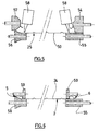
- la figure 9 est une vue agrandie du détail C de la figure 7
- la figure 10 est une vue agrandie du détail D de la figure 7
- la figure 11 est une vue partielle en coupe verticale de l'ensemble des deux panneaux représenté sur la figure 7, au niveau d'une charnière
- la figure 12 est une vue en perspective schématique d'une porte de garage sectionnelle selon l'invention, le vantail étant dans une position intermédiaire entre la position fermée et la position ouverte.
- Figure 1 is a perspective view of a panel of a sectional garage door
- Figure 2 is a side view of the panel of Figure 1
- FIG. 3a is an enlarged view of detail A of FIG.
- FIG. 3b is an enlarged view of detail B of FIG. 2
- FIG. 4 is a diagrammatic representation, in perspective, of the installation for implementing the panel manufacturing process.
- FIGS. 5 and 6 are sectional views of the installation of FIG. 4, respectively along the plane P1 and the plane P2
- Figure 7 is a perspective view of two assembled panels
- FIG. 8 is a perspective view of a reinforcing element
- FIG. 9 is an enlarged view of detail C of FIG.
- FIG. 10 is an enlarged view of detail D of FIG.
- FIG. 11 is a partial view in vertical section of the assembly of the two panels shown in FIG. 7, at the level of a hinge
- Figure 12 is a schematic perspective view of a sectional garage door according to the invention, the leaf being in an intermediate position between the closed position and the open position.
Un panneau 1 est formé à partir d'une paroi métallique sensiblement rectangulaire, par exemple une plaque de tôle 50 d'une épaisseur comprise entre 0,2 et 0,9 mm, et notamment de l'ordre de 0,5 mm. Un tel panneau 1 est destiné à la fabrication d'une porte 37 sectionnelle, typiquement de garage, comprenant un vantail 38 réalisé à partir d'une pluralité de panneaux 1 associés entre eux. La porte 37 comprend également un dormant 39, destiné à être fixé à la structure d'une construction autour d'une ouverture. Ce dormant 39 comprend deux montants verticaux 40, 41, ainsi qu'une traverse supérieure 42 sensiblement horizontale.A
On définit une première direction D1, sensiblement verticale, une deuxième direction D2, sensiblement parallèle à la traverse 42, ainsi qu'une troisième direction D3 formant avec D1 et D2 un repère orthogonal.Defining a first direction D1, substantially vertical, a second direction D2, substantially parallel to the
La porte 37 est également munie de deux rails latéraux de guidage 43. Chaque rail de guidage 43 forme un angle et comprend une première partie fixée sur un montant 40, 41 et une deuxième partie 44, 45, s'étendant selon la direction D3 depuis la traverse supérieure 42.The
La porte 37 comporte de plus une traverse arrière 46, parallèle à la traverse supérieure 43, connectant les extrémités des deuxièmes parties 44, 45 des rails 43 non liées aux montants 40, 41. Les deuxièmes parties 44, 45 des rails 43 et la traverse arrière 46 sont destinées à être fixés au plafond à l'intérieur I de la construction.The
Des moyens de guidage (supports de galets 36 associés à des galets 47) coopèrent avec les rails latéraux 43, de sorte que le vantail 38 peut être déplacé entre une position extrême fermée, dans laquelle le vantail 38, sensiblement plan et vertical, obture l'ouverture de la construction, et une position extrême ouverte, dans laquelle le vantail 38, sensiblement plan et horizontal, est situé sous le plafond de la construction, à l'intérieur I de celle-ci.Guiding means (roller supports 36 associated with rollers 47) cooperate with the lateral rails 43, so that the
L'équilibrage du vantail 38 de la porte 37 est réalisé par un système d'arbres et de ressortsThe balancing of the
Le vantail 38 comporte une pluralité (par exemple six dans une réalisation typique) de panneaux 1 analogues associés les uns aux autres au moyen de charnières 33, ces panneaux 1 s'étendant parallèlement à D2 sur toute la longueur - horizontale - du vantail 38.The
Par la suite, un panneau 1 et l'association de deux panneaux 1 adjacents sont décrits en référence au vantail 38 fermé. C'est ainsi qu'il faut comprendre les termes " horizontal ", "vertical ", " supérieur ", " inférieur ", etc.Subsequently, a
Le panneau 1 est de contour sensiblement rectangulaire et comprend tout d'abord une large bande centrale 2 longitudinale, globalement plane, formant la partie principale du panneau 1 et s'étendant d'une part verticalement selon D1 et d'autre part selon D2, sur toute sa longueur L horizontale, entre un premier et un deuxième bords 3, 4 latéraux verticaux. La longueur L du panneau 1 est sensiblement égale à la longueur - horizontale - du vantail 38.The
Le panneau 1 comprend également, de part et d'autre de la bande centrale 2, une première partie longitudinale extrême supérieure 5 en forme de poutre creuse et une seconde partie longitudinale extrême inférieure 6, également en forme de poutre creuse.The
Une partie 5, 6 en forme de poutre creuse forme un moyen de rigidification du panneau 1, un support pour la charnière d'association 33 de deux panneaux adjacents et un support des moyens d'étanchéité 15a entre deux panneaux 1 adjacents.A hollow beam-shaped
La face 24 de la bande centrale 2 de laquelle font saillie les parties longitudinales en forme de poutre creuse 5, 6 est située vers l'intérieur I de la construction. Les parties longitudinales en forme de poutre creuse 5, 6 s'étendent selon D2.The
Deux panneaux 1 adjacents sont associés l'un à l'autre par une pluralité de charnières 33.Two
Chacune des parties longitudinales en forme de poutre creuse 5, 6 est formée par pliage ou profilage de la partie extrême longitudinale correspondante de la plaque 50, c'est-à-dire une bande longeant le bord longitudinal correspondant de la plaque 50.Each of the hollow beam-shaped
La largeur ℓ5, ℓ6 des parties longitudinales en forme de poutre creuse 5, 6 - comptée verticalement selon D1- est dans la réalisation envisagée de l'ordre de 5 à 20 % de la largeur totale ℓ1 du panneau 1- également comptée verticalement selon D1.The width ℓ5, ℓ6 of the longitudinal hollow-beam-shaped
La première partie longitudinale supérieure en forme de poutre creuse 5 (figure 3a) présente une section polygonale qui comprend plusieurs portions longitudinales consécutives sensiblement planes ou légèrement incurvées, comme décrit ci-après en partant de la bande centrale 2 du panneau 1 et en poursuivant jusqu'au premier bord longitudinal 7 de la plaque 50 :
une première portion 8, ou base, située en prolongement et dans le même plan que la bande centrale 2 ;- une deuxième
portion 9, s'étendant en prolongement de la bande centrale 2 en étant inclinée par rapport au plan de la bande centrale 2 d'un angle α compris entre 10 et 30° ; - un décrochement en forme de cavité ouverte vers l'extérieur, constituant un logement 15 destiné à recevoir un joint d'étanchéité 15a;
- une troisième
portion 10, s'étendant en prolongement de la deuxièmeportion 9, et inclinée par rapport au plan de la bande centrale 2 d'un angle β compris entre 40 et 50° ; - une quatrième
portion 11 raccordée à la troisièmeportion 10 par une zone courbe 12 et s'étendant sensiblement parallèlement au plan de la bande centrale 2, et à distance de celle-ci, vers la deuxième partie longitudinale 6 du panneau 1 ; une cinquième portion 13 sensiblement perpendiculaire à la quatrième portion 11 - ou légèrement inclinée vers la deuxième partie longitudinale 6 du panneau 1 - et s'étendant sensiblement jusqu'à la bande centrale 2 ;une sixième portion 14 s'étendant sensiblement parallèlement à la bande centrale 2 vers la deuxième partie longitudinale 6 du panneau 1.La sixième portion 14 est plaquée sur la bande centrale 2 et solidarisée à celle-ci par collage.
- a
first portion 8, or base, located in extension and in the same plane as thecentral strip 2; - a
second portion 9 extending in extension of thecentral strip 2 being inclined relative to the plane of thecentral strip 2 by an angle α of between 10 and 30 °; - a recess in the form of a cavity open towards the outside, constituting a
housing 15 intended to receive a seal 15a; - a
third portion 10, extending in extension of thesecond portion 9, and inclined relative to the plane of thecentral strip 2 by an angle β between 40 and 50 °; - a
fourth portion 11 connected to thethird portion 10 by acurved area 12 and extending substantially parallel to the plane of thecentral strip 2, and at a distance therefrom, towards the secondlongitudinal portion 6 of thepanel 1; - a
fifth portion 13 substantially perpendicular to the fourth portion 11 - or slightly inclined towards the secondlongitudinal portion 6 of the panel 1 - and extending substantially to thecentral strip 2; - a
sixth portion 14 extending substantially parallel to thecentral strip 2 to the secondlongitudinal portion 6 of thepanel 1. Thesixth portion 14 is pressed onto thecentral strip 2 and secured thereto by gluing.
La deuxième partie longitudinale inférieure en forme de poutre creuse 6 (figure 3b) présente également une section polygonale qui comprend plusieurs portions longitudinales consécutives sensiblement planes ou légèrement incurvées, comme décrit ci-après en partant de la bande centrale 2 du panneau 1 et en poursuivant jusqu'au second bord longitudinal 16 de la plaque 50 :
une première portion 17, située en prolongement et dans le même plan que la bande centrale 2 ;- une deuxième
portion 18, raccordée à la premièreportion 17 par une zone courbe 19 et s'étendant vers la première partie longitudinale 5 du panneau 1, ladite deuxièmeportion 18 étant inclinée par rapport au plan de la bande centrale 2 d'un angle γ sensiblement égal à α; c'est sur cetteportion 18 qu'est comprimé le joint d'étanchéité 15a lorsque le vantail 38 est fermé; - une troisième
portion 20 s'étendant en prolongement de la deuxièmeportion 18, vers la première partie longitudinale 5 du panneau 1, et inclinée par rapport au plan de la bande centrale 2 d'un angle δ sensiblement égal à β; - une quatrième
portion 21 s'étendant sensiblement parallèlement au plan de la bande centrale 2, et à distance de celle-ci, vers la première partie longitudinale 5 du panneau 1 ; une cinquième portion 22 sensiblement perpendiculaire à la quatrième portion 21 - ou légèrement inclinée vers la première partie longitudinale 5 du panneau 1 - et s'étendant sensiblement jusqu'à la bande centrale 2 ;une sixième portion 23 s'étendant sensiblement parallèlement à la bande centrale 2 vers la première partie longitudinale 5 du panneau 1.La sixième portion 23 est plaquée sur la bande centrale 2 et solidarisée à la celle-ci par collage.
Ainsi, chacune des parties longitudinales 5, 6 du panneau 1 forme une poutre creuse dont une partie est sensiblement plane et située sensiblement dans le même plan que la bande centrale 2 (premièresportions 8 et 17, formant bases), et dont une partie est en saillie par rapport à laface 24 de la bande centrale 2. L'écartement en saillie ou hauteur - en l'espèce compté horizontalement -, c'est-à-dire la distance entre les première et quatrièmeportion et
- a
first portion 17, located in extension and in the same plane as thecentral strip 2; - a
second portion 18, connected to thefirst portion 17 by acurved zone 19 and extending towards the firstlongitudinal portion 5 of thepanel 1, saidsecond portion 18 being inclined relative to the plane of thecentral strip 2 by an angle γ substantially equal to α; it is on thisportion 18 that the seal 15a is compressed when theleaf 38 is closed; - a
third portion 20 extending in extension of thesecond portion 18, towards the firstlongitudinal portion 5 of thepanel 1, and inclined relative to the plane of thecentral strip 2 by an angle δ substantially equal to β; - a
fourth portion 21 extending substantially parallel to the plane of thecentral strip 2, and at a distance therefrom, towards the firstlongitudinal portion 5 of thepanel 1; - a
fifth portion 22 substantially perpendicular to the fourth portion 21 - or slightly inclined towards the firstlongitudinal portion 5 of the panel 1 - and extending substantially to thecentral strip 2; - a
sixth portion 23 extending substantially parallel to thecentral strip 2 to the firstlongitudinal portion 5 of thepanel 1. Thesixth portion 23 is pressed onto thecentral strip 2 and secured to the latter by gluing.
Thus, each of thelongitudinal portions panel 1 forms a hollow beam part of which is substantially planar and situated substantially in the same plane as the central strip 2 (first portions face 24 of thecentral strip 2. The projecting distance or height - in this case counted horizontally - that is to say the distance between the first andfourth portion
La présence des parties longitudinales 5, 6 en forme de poutre creuse confère une grande rigidité au panneau 1 dans sa longueur, même si ces parties 5, 6 sont creuses et vides, c'est-à-dire qu'elles ne sont remplies d'aucune matière.The presence of the
Bien entendu, si cela est souhaité, la bande centrale 2 peut comprendre un ou plusieurs moyens de raidissement 25 destinées à augmenter la rigidité du panneau 1 dans la longueur.Of course, if desired, the
Ces moyens de raidissement se présentent sous la forme de cassettes ou de plis longitudinaux.These stiffening means are in the form of cassettes or longitudinal folds.
Dans la réalisation représentée, la bande centrale 2 comporte quatre moyens de raidissement 25 équidistants s'étendant sur toute la longueur L du panneau 1 sous la forme de plis réalisés dans la plaque 50. Un pli est formé par trois lignes de plage ou de profilage longitudinales et présente ainsi, en vue de profil, la forme d'un V faisant saillie du même côté de la bande centrale 2 que les parties longitudinales 5, 6, en forme de poutre creuse, sur une hauteur de l'ordre du tiers ou de la moitié de la hauteur h des parties longitudinales 5, 6 en forme de poutre creuse.In the embodiment shown, the
On décrit à présent le procédé de fabrication du panneau 1, et l'installation pour la mise en oeuvre de ce procédé, en référence aux figures 4 à 6.The method of manufacturing the
Une tôle enroulée sur une bobine 51 est progressivement déroulée puis coupée à la longueur L souhaitée dans une unité de découpe 52. On obtient ainsi une plaque de tôle 50, sensiblement plane, à partir de laquelle sera formé le panneau 1.A sheet wound on a
La plaque 50 est sensiblement rectangulaire, de longueur L et de largeur ℓ50. Elle comprend d'une part des petits bords opposés 3, 4, qui formeront les petits bords 3, 4 du panneau 1, et d'autre part des grands bords opposés longitudinaux 7, 16.The
La plaque 50 est ensuite déplacée vers une unité de pliage ou profilage et collage 53.The
Au cours du profilage, la plaque 50 est déplacée longitudinalement selon la flèche représentée sur la figure 4, entre des galets 54, 55, 56, 57. Les galets mettent la plaque 50 en forme, d'une part en réalisant les moyens de raidissement 25, et d'autre part en repliant les parties latérales de la plaque 50 longeant respectivement le bord longitudinal 7 et le bord longitudinal 16 vers la partie centrale de la plaque 50.During the profiling, the
Un dispositif 58 dépose ensuite de la colle sur la plaque 50, longitudinalement, aux extrémités de la bande centrale. Des galets 59 appuient alors une zone de la partie repliée de la plaque contre la partie centrale de la plaque, là où la colle a été déposée, de façon à former les parties longitudinales 5, 6 du panneau 1 et à les solidariser à la bande centrale 2 du panneau 1.A
Dans la réalisation représentée, c'est la sixième portion 14, 23 des parties longitudinales 5, 6 qui est collée sur la face 24 de la bande centrale 2.In the embodiment shown, it is the
A titre d'exemple, la plaque 50 peut avoir une largeur ℓ50 de 700 mm et être découpée à une longueur L de 2400 mm. Le panneau 1 obtenu a alors la même longueur L et une largeur ℓ1 de 500 mm.By way of example, the
On décrit à présent l'assemblage de deux panneaux 1 en vue de la réalisation d'un vantail de porte, en se référant aux figures 7 à 11.We now describe the assembly of two
Dans un premier temps, on fixe un ou plusieurs éléments de renfort vertical 26 au panneau 1. Un tel élément de renfort 26 (figure 8), en métal, comprend une paroi rectangulaire plane 27 de laquelle font saillie sensiblement perpendiculairement deux parois latérales 28, 29 sensiblement identiques.In a first step, one or more vertical reinforcing
La partie extrême des parois latérales 28, 29 non liée à la paroi plane 27 présente une succession de dents 30 et de créneaux 31. Les dents 30 d'une paroi latérale 28, 29 sont repliées vers la paroi latérale opposée 29, 28 de façon à être sensiblement parallèles à la paroi plane 27. Chaque dent 30 comporte une lumière 32 dont la fonction sera indiquée ci-après.The end portion of the
Dans la réalisation représentée, trois éléments de renfort 26 sont fixés sur chacun des panneaux 1, du côté de la face 24 de la bande centrale 2, verticalement sensiblement parallèlement aux bords 3, 4 du panneau 1. A cet effet, la position et les dimensions des dents 30 et des créneaux 31 sont prévues pour que les plis en V de la bande centrale 2 puissent être logés dans les créneaux 31, les dents 30 étant quant à elles placées soit entre deux plis en V successifs, soit entre un pli en V et une partie longitudinale en forme de poutre creuse 5, 6 du panneau 1.In the embodiment shown, three reinforcing
Les éléments de renfort 26 permettent d'éviter une déformation du panneau 1 parallèlement aux parties longitudinales 5, 6, et augmentent ainsi la rigidité du panneau 1. L'invention permet donc de diminuer le nombre de renforts rapportés nécessaires, puisque des renforts sont prévus dans une seule direction, en l'espèce verticalement.The reinforcing
Les éléments de renfort 26 sont fixés par collage des dents 30 contre la face 24 de la bande centrale 2 du panneau 1. Les lumières 32 permettent d'éviter que le surplus de colle ne soit apparent.The reinforcing
Un élément de renfort 26 est fixé sensiblement à mi-distance entre les deux bords 3, 4 du panneau 1. Deux autres éléments de renfort 26 sont fixés chacun au voisinage d'un bord 3, 4.A reinforcing
Dans un deuxième temps, on assemble deux panneaux 1 adjacents.In a second step, two
Deux panneaux 1 sont placés de sorte que leurs bandes centrales 2 soient coplanaires, la première partie supérieure en forme de poutre creuse 5 d'un panneau inférieur étant parallèle et adjacente à la seconde partie inférieure en forme de poutre creuse du panneau adjacent supérieur, les bords 3, 4 respectifs des deux panneaux 1 considérés étant alignés.Two
Une charnière 33 est prévue au niveau de chacun des éléments de renfort 26 pour permettre l'articulation mutuelle des deux panneaux 1 par une pluralité de charnières.A
Une première partie de la charnière 33 est fixée par deux vis 34 sur la paroi plane 27 de l'élément de renfort 26 de l'un des panneaux 1 et sur la quatrième portion 11 de la première partie longitudinale supérieure en forme de poutre creuse 5 du panneau 1 correspondant. Une deuxième partie de la charnière 33, articulée par rapport à la première partie autour d'un axe parallèle à D2, est fixée par deux vis 35 sur la paroi plane 27 de l'élément de renfort 26 de l'autre des panneaux 1 et sur la quatrième portion 21 de la seconde partie longitudinale inférieure en forme de poutre creuse 6 du panneau 1 correspondant. Les vis 34, 35 permettent en outre de renforcer la fixation des éléments de renfort 26 sur les panneaux 1.A first part of the
Comme représenté sur la figure 11, les parties longitudinales en forme de poutre creuse respectives 5, 6 de deux panneaux 1 adjacents présentent des formes complémentaires et sont ainsi aptes à coopérer pour autoriser le mouvement de rotation d'un panneau par rapport à l'autre, et assurer le recouvrement partiel de deux panneaux adjacents dans la zone de jonction.As shown in FIG. 11, the respective hollow-beam
Du fait de la sensible égalité entre les angles α et γ, d'une part, et β et δ, d'autre part, et des dimensions respectives des différentes portions longitudinales des parties longitudinales en forme de poutre creuse 5, 6 la partie longitudinale supérieure 5 du panneau 1 inférieur est en partie logée dans le renfoncement situé sous la troisième portion 20 de la partie longitudinale inférieure 6 du panneau 1 supérieur.Because of the substantial equality between the angles α and γ, on the one hand, and β and δ, on the other hand, and the respective dimensions of the different longitudinal portions of the hollow-beam
La structure qui vient d'être décrite est telle que deux panneaux 1 adjacents du vantail 28 fermé ne sont séparés du point de vue visuel et du côté externe que par un très faible espace entre la zone courbe 19 de la partie longitudinale inférieure en forme de poutre creuse 6 et la deuxième portion 9 de la partie longitudinale supérieure en forme de poutre creuse 5. Cet espace étroit en direction verticale est peu profond en direction horizontale ce qui ne nuit pas à l'esthétique de la porte.The structure that has just been described is such that two
D'autre part, la partie 9 de la partie longitudinale supérieure en forme de poutre creuse est fortement inclinée de sorte que l'eau de pluie ou de nettoyage de même que les poussières ne peuvent stagner ou s'incruster. Cela participe également de la qualité de la porte.On the other hand, the
Egalement, l'agencement est anti pince doigt.Also, the arrangement is anti finger forceps.
Enfin, le joint d'étanchéité longitudinal 15a fixé dans le logement 15 formé par le décrochement en forme de cavité ouverte vers l'extérieur prévu sur la partie longitudinale supérieure en forme de poutre creuse 5 travaille par compression en venant contre la deuxième portion 18 placée en regard et peu écartée de la partie longitudinale inférieure en forme de poutre creuse 6. Cela est particulièrement efficace.Finally, the longitudinal seal 15a fixed in the
Un jeu suffisant est prévu entre les parties longitudinales 5, 6 en regard de deux panneaux adjacents afin de permettre la rotation relative sans obstacle de l'un des panneaux 1 par rapport à l'autre.A sufficient clearance is provided between the
L'articulation des deux parties de la charnière 33 est située au voisinage du plan sensiblement horizontal défini par le logement 15 de la partie longitudinale supérieure en forme de poutre creuse 5 et la zone courbe 19 de la partie longitudinale inférieure en forme de poutre creuse 6. Cette disposition contribue à l'efficacité.The articulation of the two parts of the
Les charnières 33 fixées sur les éléments de renfort 26 situés au voisinage d'un bord 3, 4 comportent des supports de galets 36.The hinges 33 fixed on the reinforcing
Ainsi que cela découle de ce qui précède, les panneaux 1 sont agencés de sorte que la face 24 de la bande centrale 2 de la quelle font saillie les parties longitudinales en forme de poutre creuse 5, 6 soit située vers l'intérieur I de la construction.As follows from the foregoing, the
Claims (17)
Priority Applications (1)
| Application Number | Priority Date | Filing Date | Title |
|---|---|---|---|
| EP05290991A EP1722065A1 (en) | 2005-05-09 | 2005-05-09 | Panel of hollow reinforcement beams |
Applications Claiming Priority (1)
| Application Number | Priority Date | Filing Date | Title |
|---|---|---|---|
| EP05290991A EP1722065A1 (en) | 2005-05-09 | 2005-05-09 | Panel of hollow reinforcement beams |
Publications (1)
| Publication Number | Publication Date |
|---|---|
| EP1722065A1 true EP1722065A1 (en) | 2006-11-15 |
Family
ID=35058375
Family Applications (1)
| Application Number | Title | Priority Date | Filing Date |
|---|---|---|---|
| EP05290991A Withdrawn EP1722065A1 (en) | 2005-05-09 | 2005-05-09 | Panel of hollow reinforcement beams |
Country Status (1)
| Country | Link |
|---|---|
| EP (1) | EP1722065A1 (en) |
Cited By (1)
| Publication number | Priority date | Publication date | Assignee | Title |
|---|---|---|---|---|
| US7955460B2 (en) | 2008-05-02 | 2011-06-07 | Overhead Door Corporation | Movable barriers having transverse stiffeners and methods of making the same |
Citations (4)
| Publication number | Priority date | Publication date | Assignee | Title |
|---|---|---|---|---|
| DE3922981A1 (en) * | 1988-11-25 | 1990-05-31 | Hoermann Kg | Vertically sliding door with horizontal panels |
| DE4227311A1 (en) | 1992-08-18 | 1994-02-24 | Erich Doering | Panel for ceiling or side section door - has protruding clamping fold on box profile(s) made of latter sheet metal |
| US5782283A (en) * | 1997-04-03 | 1998-07-21 | Raynor Garage Doors | Garage door construction |
| EP0943776A1 (en) * | 1998-03-20 | 1999-09-22 | Novoferm France | Panel for a sectional door, sectional door and its conditioning |
-
2005
- 2005-05-09 EP EP05290991A patent/EP1722065A1/en not_active Withdrawn
Patent Citations (4)
| Publication number | Priority date | Publication date | Assignee | Title |
|---|---|---|---|---|
| DE3922981A1 (en) * | 1988-11-25 | 1990-05-31 | Hoermann Kg | Vertically sliding door with horizontal panels |
| DE4227311A1 (en) | 1992-08-18 | 1994-02-24 | Erich Doering | Panel for ceiling or side section door - has protruding clamping fold on box profile(s) made of latter sheet metal |
| US5782283A (en) * | 1997-04-03 | 1998-07-21 | Raynor Garage Doors | Garage door construction |
| EP0943776A1 (en) * | 1998-03-20 | 1999-09-22 | Novoferm France | Panel for a sectional door, sectional door and its conditioning |
Cited By (2)
| Publication number | Priority date | Publication date | Assignee | Title |
|---|---|---|---|---|
| US7955460B2 (en) | 2008-05-02 | 2011-06-07 | Overhead Door Corporation | Movable barriers having transverse stiffeners and methods of making the same |
| US8220519B2 (en) | 2008-05-02 | 2012-07-17 | Overhead Door Corporation | Movable barriers having transverse stiffeners and methods of making the same |
Similar Documents
| Publication | Publication Date | Title |
|---|---|---|
| EP2463470B1 (en) | Framing for walls | |
| BE512172A (en) | ||
| EP1035297B1 (en) | Roller shutter box, end plate and covering profile for the box | |
| EP0943777B1 (en) | Pre-mounted and pre-adjusted sectional door, and its conditioning | |
| EP1722065A1 (en) | Panel of hollow reinforcement beams | |
| FR2800437A1 (en) | Rigid support with cover trim e.g. for door or gate has trim in form of U-section profile with single inner cavity for support | |
| FR2685136A1 (en) | PANEL, PARTICULARLY FOR CABINET DOOR, AND PARTICULARLY FOR ELECTRICAL CABINET DOOR. | |
| EP2053189B1 (en) | Chassis comprising a fixed door | |
| EP1369549B1 (en) | Self supporting doorleaf for overhead door | |
| EP0669445B1 (en) | Slat for a screen closure and furniture with such a screen | |
| EP1201869B1 (en) | Wing made of plastics, assembly method therefor and double winged opening, eg for a window | |
| EP0791700A1 (en) | Fastening holder plate and spacer for obtaining claddings in the field of construction, and claddings so obtained | |
| EP1396603B1 (en) | Sectional door leaf and door comprising such a leaf | |
| FR2516585A1 (en) | Metallic frame for doors, windows etc. - comprises uprights and cross-members which are secured together using right angled brackets | |
| FR2967443A1 (en) | Side section for use as e.g. upright of door jamb, has side walls between which grooves are formed, and top wall forming abutment for edge of door, where each groove comprises side that is formed by fold of section against one side wall | |
| FR2641809A1 (en) | Assembly device for partition framework | |
| FR2539336A1 (en) | Painting booth made from modular panels | |
| WO2022189348A1 (en) | Slide for attaching a metal shutter, in particular an anti-cyclone metal shutter | |
| FR3032221A1 (en) | COMBINATION OF PARCLOSE PROFILE AND OPENING PROFILES FOR THE PRODUCTION OF WINDOW OPENING CHASSIS AND WINDOW DOOR AND METHOD FOR PRODUCING SUNGLASSES | |
| FR2705379A3 (en) | Sealing strip for the facade of a building or the like, especially with a glazed wall | |
| EP1830027A1 (en) | Woodwork element capable of accommodating a glazed part and element with corresponding glass function | |
| BE566476A (en) | ||
| FR2723133A1 (en) | Frame for lining window aperture in building wall | |
| FR2637013A1 (en) | Sliding door assembly and method of manufacture | |
| FR2691236A1 (en) | Framework for openings in outer walls of building, esp. transformer or switching station |
Legal Events
| Date | Code | Title | Description |
|---|---|---|---|
| PUAI | Public reference made under article 153(3) epc to a published international application that has entered the european phase |
Free format text: ORIGINAL CODE: 0009012 |
|
| AK | Designated contracting states |
Kind code of ref document: A1 Designated state(s): AT BE BG CH CY CZ DE DK EE ES FI FR GB GR HU IE IS IT LI LT LU MC NL PL PT RO SE SI SK TR |
|
| AX | Request for extension of the european patent |
Extension state: AL BA HR LV MK YU |
|
| RIN1 | Information on inventor provided before grant (corrected) |
Inventor name: GUITTON, CHRISTOPHE Inventor name: ROBIN, LAURENT |
|
| AKX | Designation fees paid |
Designated state(s): AT BE BG CH CY CZ DE DK EE ES FI FR GB GR HU IE IS IT LI LT LU MC NL PL PT RO SE SI SK TR |
|
| STAA | Information on the status of an ep patent application or granted ep patent |
Free format text: STATUS: THE APPLICATION IS DEEMED TO BE WITHDRAWN |
|
| 18D | Application deemed to be withdrawn |
Effective date: 20070516 |