EP1724111A2 - Office laminator - Google Patents
Office laminator Download PDFInfo
- Publication number
- EP1724111A2 EP1724111A2 EP06009311A EP06009311A EP1724111A2 EP 1724111 A2 EP1724111 A2 EP 1724111A2 EP 06009311 A EP06009311 A EP 06009311A EP 06009311 A EP06009311 A EP 06009311A EP 1724111 A2 EP1724111 A2 EP 1724111A2
- Authority
- EP
- European Patent Office
- Prior art keywords
- support plate
- office
- laminating
- cutting device
- equipment according
- Prior art date
- Legal status (The legal status is an assumption and is not a legal conclusion. Google has not performed a legal analysis and makes no representation as to the accuracy of the status listed.)
- Granted
Links
Images


Classifications
-
- B—PERFORMING OPERATIONS; TRANSPORTING
- B32—LAYERED PRODUCTS
- B32B—LAYERED PRODUCTS, i.e. PRODUCTS BUILT-UP OF STRATA OF FLAT OR NON-FLAT, e.g. CELLULAR OR HONEYCOMB, FORM
- B32B37/00—Methods or apparatus for laminating, e.g. by curing or by ultrasonic bonding
- B32B37/14—Methods or apparatus for laminating, e.g. by curing or by ultrasonic bonding characterised by the properties of the layers
- B32B37/16—Methods or apparatus for laminating, e.g. by curing or by ultrasonic bonding characterised by the properties of the layers with all layers existing as coherent layers before laminating
- B32B37/18—Methods or apparatus for laminating, e.g. by curing or by ultrasonic bonding characterised by the properties of the layers with all layers existing as coherent layers before laminating involving the assembly of discrete sheets or panels only
- B32B37/182—Methods or apparatus for laminating, e.g. by curing or by ultrasonic bonding characterised by the properties of the layers with all layers existing as coherent layers before laminating involving the assembly of discrete sheets or panels only one or more of the layers being plastic
-
- B—PERFORMING OPERATIONS; TRANSPORTING
- B26—HAND CUTTING TOOLS; CUTTING; SEVERING
- B26D—CUTTING; DETAILS COMMON TO MACHINES FOR PERFORATING, PUNCHING, CUTTING-OUT, STAMPING-OUT OR SEVERING
- B26D1/00—Cutting through work characterised by the nature or movement of the cutting member or particular materials not otherwise provided for; Apparatus or machines therefor; Cutting members therefor
- B26D1/01—Cutting through work characterised by the nature or movement of the cutting member or particular materials not otherwise provided for; Apparatus or machines therefor; Cutting members therefor involving a cutting member which does not travel with the work
- B26D1/12—Cutting through work characterised by the nature or movement of the cutting member or particular materials not otherwise provided for; Apparatus or machines therefor; Cutting members therefor involving a cutting member which does not travel with the work having a cutting member moving about an axis
- B26D1/14—Cutting through work characterised by the nature or movement of the cutting member or particular materials not otherwise provided for; Apparatus or machines therefor; Cutting members therefor involving a cutting member which does not travel with the work having a cutting member moving about an axis with a circular cutting member, e.g. disc cutter
- B26D1/157—Cutting through work characterised by the nature or movement of the cutting member or particular materials not otherwise provided for; Apparatus or machines therefor; Cutting members therefor involving a cutting member which does not travel with the work having a cutting member moving about an axis with a circular cutting member, e.g. disc cutter rotating about a movable axis
- B26D1/18—Cutting through work characterised by the nature or movement of the cutting member or particular materials not otherwise provided for; Apparatus or machines therefor; Cutting members therefor involving a cutting member which does not travel with the work having a cutting member moving about an axis with a circular cutting member, e.g. disc cutter rotating about a movable axis mounted on a movable carriage
- B26D1/185—Cutting through work characterised by the nature or movement of the cutting member or particular materials not otherwise provided for; Apparatus or machines therefor; Cutting members therefor involving a cutting member which does not travel with the work having a cutting member moving about an axis with a circular cutting member, e.g. disc cutter rotating about a movable axis mounted on a movable carriage for thin material, e.g. for sheets, strips or the like
-
- B—PERFORMING OPERATIONS; TRANSPORTING
- B26—HAND CUTTING TOOLS; CUTTING; SEVERING
- B26D—CUTTING; DETAILS COMMON TO MACHINES FOR PERFORATING, PUNCHING, CUTTING-OUT, STAMPING-OUT OR SEVERING
- B26D1/00—Cutting through work characterised by the nature or movement of the cutting member or particular materials not otherwise provided for; Apparatus or machines therefor; Cutting members therefor
- B26D1/01—Cutting through work characterised by the nature or movement of the cutting member or particular materials not otherwise provided for; Apparatus or machines therefor; Cutting members therefor involving a cutting member which does not travel with the work
- B26D1/12—Cutting through work characterised by the nature or movement of the cutting member or particular materials not otherwise provided for; Apparatus or machines therefor; Cutting members therefor involving a cutting member which does not travel with the work having a cutting member moving about an axis
- B26D1/25—Cutting through work characterised by the nature or movement of the cutting member or particular materials not otherwise provided for; Apparatus or machines therefor; Cutting members therefor involving a cutting member which does not travel with the work having a cutting member moving about an axis with a non-circular cutting member
- B26D1/26—Cutting through work characterised by the nature or movement of the cutting member or particular materials not otherwise provided for; Apparatus or machines therefor; Cutting members therefor involving a cutting member which does not travel with the work having a cutting member moving about an axis with a non-circular cutting member moving about an axis substantially perpendicular to the line of cut
- B26D1/30—Cutting through work characterised by the nature or movement of the cutting member or particular materials not otherwise provided for; Apparatus or machines therefor; Cutting members therefor involving a cutting member which does not travel with the work having a cutting member moving about an axis with a non-circular cutting member moving about an axis substantially perpendicular to the line of cut with limited pivotal movement to effect cut
-
- B—PERFORMING OPERATIONS; TRANSPORTING
- B26—HAND CUTTING TOOLS; CUTTING; SEVERING
- B26D—CUTTING; DETAILS COMMON TO MACHINES FOR PERFORATING, PUNCHING, CUTTING-OUT, STAMPING-OUT OR SEVERING
- B26D7/00—Details of apparatus for cutting, cutting-out, stamping-out, punching, perforating, or severing by means other than cutting
-
- B—PERFORMING OPERATIONS; TRANSPORTING
- B26—HAND CUTTING TOOLS; CUTTING; SEVERING
- B26D—CUTTING; DETAILS COMMON TO MACHINES FOR PERFORATING, PUNCHING, CUTTING-OUT, STAMPING-OUT OR SEVERING
- B26D9/00—Cutting apparatus combined with punching or perforating apparatus or with dissimilar cutting apparatus
-
- B—PERFORMING OPERATIONS; TRANSPORTING
- B32—LAYERED PRODUCTS
- B32B—LAYERED PRODUCTS, i.e. PRODUCTS BUILT-UP OF STRATA OF FLAT OR NON-FLAT, e.g. CELLULAR OR HONEYCOMB, FORM
- B32B39/00—Layout of apparatus or plants, e.g. modular laminating systems
-
- B—PERFORMING OPERATIONS; TRANSPORTING
- B23—MACHINE TOOLS; METAL-WORKING NOT OTHERWISE PROVIDED FOR
- B23D—PLANING; SLOTTING; SHEARING; BROACHING; SAWING; FILING; SCRAPING; LIKE OPERATIONS FOR WORKING METAL BY REMOVING MATERIAL, NOT OTHERWISE PROVIDED FOR
- B23D35/00—Tools for shearing machines or shearing devices; Holders or chucks for shearing tools
- B23D35/008—Means for changing the cutting members
-
- B—PERFORMING OPERATIONS; TRANSPORTING
- B32—LAYERED PRODUCTS
- B32B—LAYERED PRODUCTS, i.e. PRODUCTS BUILT-UP OF STRATA OF FLAT OR NON-FLAT, e.g. CELLULAR OR HONEYCOMB, FORM
- B32B37/00—Methods or apparatus for laminating, e.g. by curing or by ultrasonic bonding
- B32B37/0046—Methods or apparatus for laminating, e.g. by curing or by ultrasonic bonding characterised by constructional aspects of the apparatus
- B32B2037/0061—Methods or apparatus for laminating, e.g. by curing or by ultrasonic bonding characterised by constructional aspects of the apparatus the apparatus being an office laminator
-
- B—PERFORMING OPERATIONS; TRANSPORTING
- B32—LAYERED PRODUCTS
- B32B—LAYERED PRODUCTS, i.e. PRODUCTS BUILT-UP OF STRATA OF FLAT OR NON-FLAT, e.g. CELLULAR OR HONEYCOMB, FORM
- B32B38/00—Ancillary operations in connection with laminating processes
- B32B38/0004—Cutting, tearing or severing, e.g. bursting; Cutter details
-
- Y—GENERAL TAGGING OF NEW TECHNOLOGICAL DEVELOPMENTS; GENERAL TAGGING OF CROSS-SECTIONAL TECHNOLOGIES SPANNING OVER SEVERAL SECTIONS OF THE IPC; TECHNICAL SUBJECTS COVERED BY FORMER USPC CROSS-REFERENCE ART COLLECTIONS [XRACs] AND DIGESTS
- Y10—TECHNICAL SUBJECTS COVERED BY FORMER USPC
- Y10T—TECHNICAL SUBJECTS COVERED BY FORMER US CLASSIFICATION
- Y10T156/00—Adhesive bonding and miscellaneous chemical manufacture
- Y10T156/12—Surface bonding means and/or assembly means with cutting, punching, piercing, severing or tearing
- Y10T156/1317—Means feeding plural workpieces to be joined
-
- Y—GENERAL TAGGING OF NEW TECHNOLOGICAL DEVELOPMENTS; GENERAL TAGGING OF CROSS-SECTIONAL TECHNOLOGIES SPANNING OVER SEVERAL SECTIONS OF THE IPC; TECHNICAL SUBJECTS COVERED BY FORMER USPC CROSS-REFERENCE ART COLLECTIONS [XRACs] AND DIGESTS
- Y10—TECHNICAL SUBJECTS COVERED BY FORMER USPC
- Y10T—TECHNICAL SUBJECTS COVERED BY FORMER US CLASSIFICATION
- Y10T156/00—Adhesive bonding and miscellaneous chemical manufacture
- Y10T156/12—Surface bonding means and/or assembly means with cutting, punching, piercing, severing or tearing
- Y10T156/1378—Cutter actuated by or secured to bonding element
Definitions
- the invention relates to an office appliance for processing sheet material such as paper and / or films with a support plate for supporting the sheet material during the machining process and with at least one of the support plate associated cutting device.
- Office equipment of the aforementioned type are used for the trimming of sheet material such as paper, transparencies or photos.
- they are designed as pure cutters and have a support plate on which the sheet material to be trimmed for the cutting process can be placed.
- a cutting device usually in the form of a lever cutting device, is arranged on one edge of the support plate.
- cutters are known which, instead of a lever cutting device, have a roll cutting device in which a rotatably mounted disk knife is mounted on a knife carriage which can be moved on a guide rail.
- guillotines and slitter cutters are combined, either by arrangement on two parallel sides of the platen or by interchangeable assignment to one side of the platen.
- laminators are known to weld documents, such as leaflets, certificates, ID cards, etc., between two transparent plastic films to protect them from dirt and damage.
- the sheet material can be placed between two loose foils.
- the two films can also be in the form of a laminating bag, in which the two laminating films are welded together at up to three side edges.
- the laminating films are transparent so that the sheet material remains visible and readable. They maintain this transparency even after welding.
- the laminating films are usually formed as so-called composite films (see. Ullmann's Encyclopedia of Industrial Chemistry, 4th Edition, Volume 11, 1976, page 684 and Volume 14, 1977, page 249 ).
- the laminators used for the laminating process have a housing with a front side and a back side. Between the front and back extends a flat flow channel, which has on the front side a feed opening and on the back of an outlet opening for the combination of sheet material and films.
- a laminating device is arranged, which usually consists of two heated laminating rollers, which are driven in the conveying direction and between which passes through the combination of sheet material and films.
- the laminating rollers exert pressure on the continuous combination and at the same time heat the films. In this way, the films stick together with the sheet material to be welded in as well as at the edges.
- the laminating rollers ensure that the combination of sheet material and films is transported through the laminator to the outlet opening.
- the invention has for its object to further develop an office equipment of the type mentioned.
- the office device in addition to the at least one cutting device has at least one laminating device for laminating sheet material with at least one film.
- the basic idea of the invention is thus to combine two or more devices with different functions to form a combined office device.
- This summary provides significant benefits.
- the space requirement of the office device according to the invention is substantially lower.
- Pruning a sheet to prepare for a subsequent lamination can be done without moving, which is convenient and saves time.
- the laminating device is arranged or attachable to one side of the support plate, wherein preferably its feed opening for the introduction of sheet material and film (s) faces the platen, in particular such that the underside of the feed opening flush lies with the top of the platen.
- the platen has a dual function, since it can perform its supporting function both in the cutting process and in the feeding of the combination of sheet material and film. This results in a particularly low space requirement.
- the at least one cutter should be located or attachable to another side of the platen. It is expedient when the laminating device is arranged or attachable to a side of the platen which extends transversely to the side on which the at least one cutting device is arranged or attachable.
- the cutting device may be formed as a lever cutting device having a pivotally mounted blade arm with a blade held thereon and a fixed blade held stationary on the support plate.
- the cutting device may also be designed as a slitter-cutting device which has a knife carriage which can be moved on a guide rail and a disk knife rotatably mounted therein.
- both alternatives can also be combined with one another at the office appliance, for example in such a way that the lever cutting device is arranged or attachable on one side of the base and the roll cutting device on another side of the base, namely expediently the cutting devices extend parallel to one another and the laminating device is arranged or attachable between them on a side extending transversely thereto.
- the cutting device (s) and / or the laminator is or are detachably attached to the support plate, it being additionally possible for the cutting device (s) to be interchangeable with one another and / or with the laminating device is formed or are.
- the support plate, on the one hand, and the cutting device (s) and / or laminating device, on the other hand can have complementary holding elements, by means of which they can be attached or attached to one side of the support.
- the holding elements used may have latching devices, which are expediently designed such that they are self-latching when attaching the cutting device (s) or laminating device, but require a releasing operation of the latching device upon removal.
- the laminating device can be designed as a hot laminating device in order to allow a welding of sheet material and films to be thermally activated.
- this requires an electric connection for the heater, which can additionally be used to drive the laminating rollers by motor.
- the laminator is designed as a cold laminating, in which the laminating rollers by hand, for example via a rotary handle, are driven.
- cold laminators can also have an electric drive for the laminating rollers.
- hot laminating devices can also have a manually operable roller drive.
- At least one storage compartment is provided below the support plate, preferably at a horizontal distance from the at least one cutting device.
- This opens up the possibility to use the space not previously used in cutters below the platen as a storage compartment.
- this tray can be office equipment such as stapler, stapler or the like, but also accommodate other office supplies such as staples, writing utensils or sheet material such as paper or films without additional space.
- the storage compartment is expediently openable in that the support plate is at least partially removable from the region of the storage compartment, for example by at least partial folding up or lateral displacement.
- the at least one storage compartment or a part thereof is sealed airtight. This can be done, for example, by the storage compartment containing or consisting of an airtight but openable box.
- the invention further provides that the storage compartment is divided into compartments to keep different items separately from each other and thus stored. Furthermore, it is proposed that the support plate in the storage compartment is at least transparent. In this way, it can be detected at a glance whether the desired office material is actually present in the storage compartment.
- the size of the storage compartment should make the best possible use of the space under the support plate. It is therefore advisable to provide at least 50% of the support plate for the underlying storage compartment, since the space below the support plate is usually empty and the space for the reception of office supplies can not be large enough. In particular, the storage compartment should also be so large that there provided for the lamination Blattgut, in particular the necessary films can be stored.
- the office appliance is provided with its own power supply in the form of a battery or a rechargeable battery, in order, e.g. to supply the laminator with electric current.
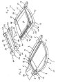
- the office appliance 1 shown in FIGS. 1 and 2 has a frame plate 2, the horizontal upper side of which forms a support plate 3 for the support of sheet material. At the upper side of the frame plate 2 is a lever cutter 4.
- the lever cutting device 4 has a knife arm 5 which can be pivoted in a bearing 6 about a horizontal axis extending transversely to the longitudinal side thereof is stored.
- the knife arm 5 is provided on its underside substantially over its entire length with a cutting blade, which is hidden in this view.
- a handle 7 is formed, via which the blade arm 5 can be pivoted about the bearing 6 upwards and downwards. In the position shown, the blade arm 5 is in the lower end position.
- the cover plate 8 can therefore be pivoted from the closed position shown in Figure 1 in the approximately vertical position shown in Figure 2.
- a storage compartment 10 which is designed as a bottom 11 having, open at the top and hinged in the frame plate 2, removable tray 12 is formed.
- the tray 12 is divided by vertical webs - for example, designated 13 - so that the storage compartment 10 has a plurality of separate sub-compartments. In these compartments, office supplies or small office equipment can be accommodated.
- sheet material can be stored.
- a H Schott al. 14 On the side of the frame plate 2, which extends adjacent to the bearing 6 transversely to the side on which the lever cutter 4 is arranged, a H Scholaminier noticed 14 is mounted. It has a housing 15 which is interspersed in the direction of the arrow A by a passage channel of low height.
- the passage channel has on the support plate 3 side facing a feed opening 16 and on the side facing away from an outlet opening.
- two laminating rollers not visible here are arranged one above the other, which form between them a laminating gap which extends over the width of the passage channel.
- the laminating rollers are heated and driven in opposite directions so that their roller shells move in the nip in the direction of the outlet opening.
- the office appliance 1 has control buttons 17, 18, via which the hot laminating device 14 can be switched on and off.
- the heating of the laminating rollers is controlled while turned on pressing the other control knob 18 in the direction of arrow B, the drive of the laminating and after the lamination also off again.
- the sheet material to be trimmed are placed on the support plate 3 and the blade arm 5 is pivoted about the bearing 6 upwards.
- the sheet material is then moved so far that the cut off Section on the side at which the lever cutter 4 is mounted, projects beyond the support plate 3.
- the blade arm 5 is pivoted about the bearing 6 down to the position shown.
- a combination 19 of sheet material to be laminated and laminating films is placed on the platen 3 and inserted into the feed opening 16 until the laminating rollers detect the sheet-film combination 19.
- the laminating rollers then transport this combination 19 through the hot laminating device 14 in the direction of the arrow A.
- the combination 19 is compressed and at the same time so far heated that a connection between films and sheet material, at the edges also a compound of the films between each other, is effected.
- the office appliance 21 shown in FIG. 3 has a cold laminating device 22. All other parts of the office equipment 21 are in accordance with the corresponding parts of the office equipment 1 according to Figs. 1 and 2, so that the same reference numerals have been used for these parts in Fig. 2 and for the description of these parts in the above description of the office equipment 1 according to the figures 1 and 2 is referred to.
- the cold laminating device 22 is disposed at the same place as the hot laminating device 11 at the office machine 1 according to Figures 1 and 2. It has a housing 23 which is penetrated by a extending in the direction of the arrow C passage channel low height.
- the passage channel has on the support plate 3 side facing a feed opening 24 and on the side facing away from an outlet opening.
- two superposed laminating rollers are also provided, the axes of which extend parallel to that of the bearing 6.
- the laminating rollers form between them a laminating gap which extends across the width of the passage channel.
- the upper laminating roller is connected to an externally accessible rotary knob 25.
- the lower laminating roller is coupled to the upper via a spur gear so that the two laminating rollers rotate in opposite directions.
- a cutting operation proceeds as described for the office equipment 1.
- a combination 26 of sheet material to be laminated and two-sided applied films is placed on the support plate 3 and inserted into the supply opening 24 in the direction of arrow C until the front end of the combination 26 enters the laminating gap.
- the knob 25 is rotated in the direction of arrow D by hand.
- the laminating rollers are driven in the opposite direction so that the sheet material-film combination 26 in the direction of arrow C. is transported by the cold laminating device 22.
- the combination 26 is pressed so much that sheet material and foils stick together.
- the office appliance 31 shown in Figure 4 has a substantially rectangular outline frame plate 32, the horizontal top forms a support plate 33 for the support of sheet material.
- a lever cutting device 34 On the upper longitudinal side is a lever cutting device 34 and on the lower longitudinal side of a roller cutting device 35 is arranged. Both cutting devices 34, 35 are parallel to each other.
- the lever cutting device 34 has a knife arm 36 which is pivotally mounted in a bearing 37 about a horizontal axis extending transversely to the longitudinal side thereof.
- the knife arm 36 is provided over its entire length on its underside with a cutting blade, which is hidden in this view.
- a handle 38 is formed, via which the blade arm 36 can be pivoted upwards and downwards. In the position shown, the blade arm 36 is in the lower end position.
- the roller cutting device 35 has a guide rail 39 which is spaced from the support plate 33 parallel to the cutting edge or cutting direction of the lever cutting device 34 between two holding blocks 40, 41st extends.
- a knife carriage 42 is guided displaceably in the direction of the longitudinal axis of the guide rail 39. It can be pushed back and forth by hand over the handle 43.
- a disc knife is rotatably mounted, which is not visible here, because it is covered by a protective cap 44.
- the storage takes place about a horizontal axis 45, which extends transversely to the longitudinal axis of the guide rail 39.
- the disc knife protrudes downward beyond the knife carriage 42 and rests on a counter knife rail 46, which is inserted into the support plate 33 and extends parallel to the guide rail 39.
- a part of the support plate 3 is separated from the rest of the part and forms a cover 47.
- the cover 47 is connected via a hinge 48 with the remaining part of the support plate 33 and can to this hinge 48 from the horizontal and flush with the rest of the part Platen 33 located position are folded up, similar to the office device 1 (see Figure 2).
- Below the cover plate 47 is - as in the office equipment 1, 21 according to Figures 1 to 3 - a storage compartment which is cup-shaped and the bottom is bounded by a bottom.
- the storage compartment is open at the top and is closed by the cover 47. This is designed to be transparent, so that the contents of the storage compartment can be seen from the outside.
- the storage compartment is so large that paper can also be loaded. It is also possible to place in the storage compartment an airtight box and to prevent air-sensitive articles such as e.g. Photo papers, protected insert. Instead, between cover plate 47 and frame plate 32 may be provided a circumferential seal over which an airtight seal can be achieved.
- One of the two laminating devices 51, 52 can be detachably connected to the side of the frame plate 32, on which the arrow E is directed, to the office appliance 31.
- complementary latching devices 53, 54, 55, 56 are provided on the frame plate 32 and on the laminating devices 51, 52, which engage with one another in a nested state. By unlocking the respectively associated with the frame plate 32 lamination 51 and 52 can be removed again.
- the hot laminating device 51 shown adjacent to the frame plate 32 has a housing 57 which is penetrated in the direction of the arrow A by a passage passage of low height.
- the passage channel has on the support plate 33 side facing a feed opening 58 and on the opposite side an outlet opening.
- the H thoroughlylaminier Ran 51 is formed as well as the H thoroughlylaminier Ran 13 in the office equipment 1 according to Figures 1 and 2, so that reference is made to the description thereof.
- the hot laminating device 51 has control buttons 59, 60, via which the hot laminating device 51 can be switched on and off.
- the heating of the laminating rollers is controlled via the control knob 59, while the drive of the laminating rollers is switched on when the other operating knob 60 is pressed and also switched off again after the laminating process.
- the cold-laminating device 52 remote from the frame plate 32 corresponds to the cold-laminating device 22 in the office appliance 21 according to FIG. 3. It has a housing 61 which is penetrated by a small-height passage channel extending in the direction of the arrow E.
- the passage channel has on the support plate 33 side facing a feed opening 62 and on the side facing away from an outlet opening.
- the laminating device 52 is identical to the laminating device 22 in the office equipment 21 according to FIG. 3, so that reference is made to the description there.
- the upper laminating roller is connected to an externally accessible rotary knob 63, so that the cold laminating device 52 is driven by hand.
- the office appliance 71 shown in FIG. 5 has a substantially rectangular frame plate 72, the horizontal upper side of which forms a support plate 73 for the support of sheet material.
- the larger part of the support plate 73 is separated from the rest of the part and forms a cover plate 74. It is pivotally mounted on one side via a hinge 75, so that it lies from a horizontal position in which the cover plate 74 is flush with the support plate 73 in the shown, substantially vertical position is pivotable.
- a storage compartment 76 which is designed as a hinged in the frame plate 72, - shown here lifted out - open tray 76 is formed.
- the storage tray 77 has a bottom 78 and is divided by vertical, from the bottom 78 upstanding webs - for example, designated 79 - so divided that the storage compartment 76 has a plurality of separate sub-compartments. In these compartments, office supplies or small office equipment can be accommodated.
- the frame plate 72 has a frame bottom 80. When the tray 77 is hung in the frame plate 72, remains between the bottom 78 of the tray 77 and the frame bottom 80 a distance. The resulting space can be used to accommodate sheet 81.
- the device On the side of the frame plate 72 which is adjacent to the hinge 75, the device, shown in parallel, can be attached by way of complementary latching elements.
- a H mustlaminier
- 82 - it corresponds to the H mustlaminier recruited 51 in the office equipment 31 of Figure 4 -
- a Kaltlaminier driving 83 it corresponds to the Kaltlaminier engaged 52 in the office equipment 31 of Figure 4 -
- a slitter 84 - it corresponds to the slitter 35 in the Office unit 31 according to FIG. 4 -
- a lever cutting device 85 - corresponds to the lever cutting device 34 in the office device 31 according to FIG. 4.
- the roller cutting device 84 and the lever cutting device 86 differ from the roller cutting device 35 or lever cutting device 34 in the office device 31 according to FIG in that they do not form a unit with the frame plate 72, but are detachable from it or can be attached to it by way of said latching elements, in each case alternatively.
- the office device 71 can be connected to one of the laminators 82, 83 or to the roller cutter 84 or to the lever cutter 85.
- 72 complementary locking elements can be provided on the other sides of the frame plate, so that the office device 71 in any manner with one of the laminators 82, 83 and the roller cutter 84 and the lever cutter 85 can be combined so that the combination shown in Figure 4 results.
- one of the laminators 82, 83 may be combined with one of the cutters 84, 85 to provide the combinations shown in Figures 1-3.
Landscapes
- Life Sciences & Earth Sciences (AREA)
- Forests & Forestry (AREA)
- Engineering & Computer Science (AREA)
- Mechanical Engineering (AREA)
- Folding Of Thin Sheet-Like Materials, Special Discharging Devices, And Others (AREA)
- Lining Or Joining Of Plastics Or The Like (AREA)
Abstract
Description
Die Erfindung betrifft ein Bürogerät für die Bearbeitung von Blattgut wie Papier und/oder Folien mit einer Auflageplatte zur Abstützung des Blattgutes beim Bearbeitungsvorgang und mit zumindest einer der Auflageplatte zugeordneten Schneideinrichtung.The invention relates to an office appliance for processing sheet material such as paper and / or films with a support plate for supporting the sheet material during the machining process and with at least one of the support plate associated cutting device.
Bürogeräte der vorgenannten Art dienen der Beschneidung von Blattgut wie Papier, Folien oder Fotos. Im Stand der Technik sind sie als reine Schneidgeräte ausgebildet und weisen eine Auflageplatte auf, auf der das zu beschneidende Blattgut für den Schneidvorgang aufgelegt werden kann. An einem Rand der Auflageplatte ist eine Schneideinrichtung, meist in Form einer Hebelschneideinrichtung, angeordnet. Um Fotos genauer und sauberer beschneiden zu können, sind Schneidgeräte bekannt, die statt einer Hebelschneideinrichtung eine Rollenschneideinrichtung aufweisen, bei der ein drehbar gelagertes Scheibenmesser an einem auf einer Führungsschiene verfahrbaren Messerwagen gelagert ist. Bei dem Schneidgerät gemäß der
Daneben sind Laminiergeräte bekannt, um Schriftstücke, beispielsweise Prospektblätter, Urkunden, Ausweise etc., zwischen zwei durchsichtigen Kunststoffolien einzuschweißen, um sie vor Verschmutzung und Beschädigung zu schützen. Für den Laminiervorgang kann das Blattgut zwischen zwei lose Folien gelegt werden. Statt dessen können die beiden Folien aber auch in Form einer Laminiertasche vorliegen, bei der die beiden Laminierfolien an bis zu drei Seitenkanten miteinander verschweißt sind. In die Laminiertasche kann das zu laminierende Blattgut eingelegt werden. Die Laminierfolien sind transparent, damit das Blattgut sichtbar und lesbar bleibt. Sie behalten diese Transparenz auch nach dem Verschweißen bei. Hierzu sind die Laminierfolien gewöhnlich als sogenannte Verbundfolien ausgebildet (vgl.
Die für den Laminiervorgang verwendeten Laminiergeräte weisen ein Gehäuse mit einer Frontseite und einer Rückseite auf. Zwischen Front- und Rückseite erstreckt sich ein flacher Durchlaufkanal, der auf der Frontseite eine Zuführöffnung und auf der Rückseite eine Austrittsöffnung für die Kombination aus Blattgut und Folien hat. Innerhalb des Gehäuses ist eine Laminiereinrichtung angeordnet, die gewöhnlich aus zwei beheizten Laminierwalzen besteht, die in Förderrichtung angetrieben sind und zwischen denen die Kombination aus Blattgut und Folien hindurchläuft. Dabei üben die Laminierwalzen Druck auf die durchlaufende Kombination aus und erhitzen gleichzeitig die Folien. Auf diese Weise verkleben die Folien mit dem einzuschweißenden Blattgut sowie an den Rändern untereinander. Die Laminierwalzen sorgen dafür, daß die Kombination aus Blattgut und Folien durch das Laminiergerät zur Austrittsöffnung transportiert wird.The laminators used for the laminating process have a housing with a front side and a back side. Between the front and back extends a flat flow channel, which has on the front side a feed opening and on the back of an outlet opening for the combination of sheet material and films. Within the housing, a laminating device is arranged, which usually consists of two heated laminating rollers, which are driven in the conveying direction and between which passes through the combination of sheet material and films. The laminating rollers exert pressure on the continuous combination and at the same time heat the films. In this way, the films stick together with the sheet material to be welded in as well as at the edges. The laminating rollers ensure that the combination of sheet material and films is transported through the laminator to the outlet opening.
Statt thermisch arbeitender Laminiergeräte sind auch einfache Laminiergeräte bekannt, die keiner elektrischen Stromzuführung bedürfen und bei denen die Verbindung von Blattgut und Folien allein durch Druckausübung bewirkt wird. Hierzu sind die Folien auf den dem Blattgut zugewandten Seiten mit einem druckempfindlichen Haftkleber versehen, der nicht selbstklebend ist, also erst durch Druckausübung aktiviert wird. Die Kombination aus Blattgut und Folien wird zwischen den Laminierwalzen zusammengepreßt. Der Antrieb der Laminierwalzen erfolgt von Hand.Instead of thermally operating laminating and simple laminating are known which require no electrical power supply and in which the connection of sheet material and films is effected solely by applying pressure. For this purpose, the films are provided on the sides facing the sheet material with a pressure-sensitive adhesive, which is not self-adhesive, so it is activated only by applying pressure. The combination of sheet material and films is compressed between the laminating rollers. The drive of the laminating rollers is done by hand.
Der Erfindung liegt die Aufgabe zugrunde, ein Bürogerät der eingangs genannten Art fortzuentwickeln.The invention has for its object to further develop an office equipment of the type mentioned.
Diese Aufgabe wird erfindungsgemäß dadurch gelöst, daß das Bürogerät zusätzlich zu der zumindest einen Schneideinrichtung wenigstens eine Laminiereinrichtung zur Laminierung von Blattgut mit zumindest einer Folie aufweist.This object is achieved in that the office device in addition to the at least one cutting device has at least one laminating device for laminating sheet material with at least one film.
Grundgedanke der Erfindung ist es also, zwei - oder mehr - Einrichtungen mit unterschiedlichen Funktionen zu einem kombinierten Bürogerät zusammenzufassen. Durch diese Zusammenfassung werden erhebliche Vorteile erzielt. So ist der Platzbedarf des erfindungsgemäßen Bürogeräts wesentlich geringer. Auch bei der Handhabung ergeben sich durch die zusammenliegende Anordnung von Schneideinrichtung und Laminiereinrichtung Vorteile. Die Beschneidung eines Blattguts zwecks Vorbereitung eines anschließenden Laminiervorgangs kann ohne Ortswechsel durchgeführt werden, was praktisch ist und Zeit spart.The basic idea of the invention is thus to combine two or more devices with different functions to form a combined office device. This summary provides significant benefits. Thus, the space requirement of the office device according to the invention is substantially lower. Also in handling resulting from the combination arrangement of cutting device and laminator advantages. Pruning a sheet to prepare for a subsequent lamination can be done without moving, which is convenient and saves time.
In Ausbildung der Erfindung ist vorgesehen, daß die Laminiereinrichtung an einer Seite der Auflageplatte angeordnet oder anbringbar ist, wobei vorzugsweise ihre Zuführöffnung für das Einführen von Blattgut und Folie(n) der Auflageplatte zugewandt ist, und zwar insbesondere derart, daß die Unterseite der Zuführöffnung bündig mit der Oberseite der Auflageplatte liegt. Auf diese Weise kommt der Auflageplatte eine Doppelfunktion zu, da sie ihre Unterstützungsfunktion sowohl beim Schneidvorgang als auch bei der Zuführung der Kombination von Blattgut und Folie ausüben kann. Hierdurch entsteht ein besonders geringer Raumbedarf.In an embodiment of the invention it is provided that the laminating device is arranged or attachable to one side of the support plate, wherein preferably its feed opening for the introduction of sheet material and film (s) faces the platen, in particular such that the underside of the feed opening flush lies with the top of the platen. In this way, the platen has a dual function, since it can perform its supporting function both in the cutting process and in the feeding of the combination of sheet material and film. This results in a particularly low space requirement.
Wenn die Laminiereinrichtung an einer Seite der Auflageplatte angeordnet ist, sollte die zumindest eine Schneideinrichtung an einer anderen Seite der Auflageplatte angeordnet oder anbringbar sein. Dabei ist es zweckmäßig, wenn die Laminiereinrichtung an einer Seite der Auflageplatte angeordnet oder anbringbar ist, die quer zu der Seite verläuft, an der die zumindest eine Schneideinrichtung angeordnet oder anbringbar ist.When the laminator is disposed on one side of the platen, the at least one cutter should be located or attachable to another side of the platen. It is expedient when the laminating device is arranged or attachable to a side of the platen which extends transversely to the side on which the at least one cutting device is arranged or attachable.
Die Schneideinrichtung kann als Hebelschneideinrichtung ausgebildet sein, die einen schwenkbar gelagerten Messerarm mit daran gehaltener Schneide und ein ortsfest an der Auflageplatte gehaltenes Gegenmesser aufweist. Alternativ dazu kann die Schneideinrichtung auch als Rollenschneideinrichtung ausgebildet sein, die einen auf einer Führungsschiene verfahrbaren Messerwagen und ein darin drehbar gelagertes Scheibenmesser aufweist. In einer besonders bevorzugten Ausführungsform können beide Alternativen aber auch an dem Bürogerät miteinander kombiniert sein, beispielsweise in der Art, daß die Hebelschneideinrichtung an einer Seite der Unterlage und die Rollenschneideinrichtung an einer anderen Seite der Unterlage angeordnet oder anbringbar sind, und zwar zweckmäßigerweise so, daß die Schneideinrichtungen parallel zueinander verlaufen und die Laminiereinrichtung zwischen ihnen an einer quer dazu verlaufenden Seite angeordnet oder anbringbar ist.The cutting device may be formed as a lever cutting device having a pivotally mounted blade arm with a blade held thereon and a fixed blade held stationary on the support plate. Alternatively, the cutting device may also be designed as a slitter-cutting device which has a knife carriage which can be moved on a guide rail and a disk knife rotatably mounted therein. In a particularly preferred embodiment, however, both alternatives can also be combined with one another at the office appliance, for example in such a way that the lever cutting device is arranged or attachable on one side of the base and the roll cutting device on another side of the base, namely expediently the cutting devices extend parallel to one another and the laminating device is arranged or attachable between them on a side extending transversely thereto.
Besonders zweckmäßig ist es, wenn die Schneideinrichtung(en) und/oder die Laminiereinrichtung lösbar an der Auflageplatte angebracht ist bzw. sind, wobei zusätzlich vorgesehen sein kann, daß die Schneideinrichtung(en) untereinander und/oder mit der Laminiereinrichtung austauschbar ausgebildet ist bzw. sind. Hierzu können die Auflageplatte einerseits sowie Schneideinrichtung(en) und/oder Laminiereinrichtung andererseits komplementäre Halteelemente aufweisen, über die sie an einer Seite der Unterlage anbringbar oder angebracht ist bzw. sind.It is particularly expedient if the cutting device (s) and / or the laminator is or are detachably attached to the support plate, it being additionally possible for the cutting device (s) to be interchangeable with one another and / or with the laminating device is formed or are. For this purpose, the support plate, on the one hand, and the cutting device (s) and / or laminating device, on the other hand, can have complementary holding elements, by means of which they can be attached or attached to one side of the support.
Die verwendeten Halteelemente können Rasteinrichtungen aufweisen, die zweckmäßigerweise derart ausgebildet sind, daß sie beim Anbringen der Schneideinrichtung(en) bzw. Laminiereinrichtung selbsteinrastend sind, jedoch bei Abnahme eine Freigabebetätigung der Rasteinrichtung erfordern.The holding elements used may have latching devices, which are expediently designed such that they are self-latching when attaching the cutting device (s) or laminating device, but require a releasing operation of the latching device upon removal.
Die Laminiereinrichtung kann als Heißlaminiereinrichtung ausgebildet sein, um ein Verschweißen von Blattgut und thermisch zu aktivierenden Folien zu ermöglichen. Dies erfordert jedoch einen elektrischen Anschluß für die Heizeinrichtung, der zusätzlich dazu genutzt werden kann, die Laminierwalzen motorisch anzutreiben. Ohne elektrischen Anschluß kommt man aus, wenn die Laminiereinrichtung als Kaltlaminiereinrichtung ausgebildet ist, bei der die Laminierwalzen von Hand, beispielsweise über einen Drehgriff, antreibbar sind. Es versteht sich, daß Kaltlaminiereinrichtungen auch einen elektrischen Antrieb für die Laminierwalzen haben können. Umgekehrt können Heißlaminiereinrichtungen aber auch einen handbetätigbaren Walzenantrieb haben.The laminating device can be designed as a hot laminating device in order to allow a welding of sheet material and films to be thermally activated. However, this requires an electric connection for the heater, which can additionally be used to drive the laminating rollers by motor. Without electrical connection one comes off when the laminator is designed as a cold laminating, in which the laminating rollers by hand, for example via a rotary handle, are driven. It is understood that cold laminators can also have an electric drive for the laminating rollers. Conversely, however, hot laminating devices can also have a manually operable roller drive.
Nach der Erfindung ist ferner vorgesehen, daß unterhalb der Auflageplatte wenigstens ein Ablagefach vorgesehen ist, und zwar vorzugsweise in horizontalem Abstand zu der zumindest einen Schneideinrichtung. Hierdurch wird die Möglichkeit eröffnet, den bisher bei Schneidgeräten nicht genutzten Raum unterhalb der Auflageplatte als Ablagefach zu nutzen. In diesem Ablagefach lassen sich Bürogeräte wie Enthefter, Hefter oder dergleichen, aber auch andere Büromaterialien wie Heftklammern, Schreibgeräte oder Blattgut wie Papier oder Folien ohne zusätzlichen Platzbedarf unterbringen. Hierdurch sind die Voraussetzungen geschaffen, daß die vor oder nach einem Schneid- und/oder Laminiervorgang anfallenden Vorgänge zeitnah und ohne Verzögerung durchgeführt werden können und daß der Platz um das Bürogerät frei bleibt für die eigentliche Büroarbeit.According to the invention it is further provided that at least one storage compartment is provided below the support plate, preferably at a horizontal distance from the at least one cutting device. This opens up the possibility to use the space not previously used in cutters below the platen as a storage compartment. In this tray can be office equipment such as stapler, stapler or the like, but also accommodate other office supplies such as staples, writing utensils or sheet material such as paper or films without additional space. As a result, the conditions are created that the occurring before or after a cutting and / or laminating process can be carried out promptly and without delay and that the space around the office equipment remains free for the actual office work.
Das Ablagefach ist zweckmäßigerweise dadurch öffenbar, daß die Auflageplatte zumindest teilweise von dem Bereich des Ablagefachs entfernbar ist, beispielsweise durch zumindest teilweises Hochklappen oder seitliches Verschieben. Für die Lagerung von gegen Lufteinfluß empfindliche Materialien, beispielsweise Fotopapiere, kann vorgesehen sein, daß das zumindest eine Ablagefach oder ein Teil davon luftdicht abgedichtet ist. Dies kann beispielsweise dadurch geschehen, daß das Ablagefach eine luftdichte, jedoch öffenbare Box enthält oder daraus besteht.The storage compartment is expediently openable in that the support plate is at least partially removable from the region of the storage compartment, for example by at least partial folding up or lateral displacement. For the storage of air-sensitive materials, such as photographic papers, it can be provided that the at least one storage compartment or a part thereof is sealed airtight. This can be done, for example, by the storage compartment containing or consisting of an airtight but openable box.
Die Erfindung sieht des weiteren vor, daß das Ablagefach in Teilfächer aufgeteilt ist, um verschiedene Gegenstände getrennt voneinander und damit geordnet aufzubewahren. Des weiteren ist vorgeschlagen, daß die Auflageplatte im Bereich des Ablagefachs zumindest durchsichtig ist. Auf diese Weise kann mit einem Blick erfaßt werden, ob das gewünschte Büromaterial tatsächlich in dem Ablagefach vorhanden ist.The invention further provides that the storage compartment is divided into compartments to keep different items separately from each other and thus stored. Furthermore, it is proposed that the support plate in the storage compartment is at least transparent. In this way, it can be detected at a glance whether the desired office material is actually present in the storage compartment.
Die Größe des Ablagefachs sollte den Raum unter der Auflageplatte möglichst gut nutzen. Es empfiehlt sich deshalb, zumindest 50 % der Auflageplatte für das darunter liegende Ablagefach bereitzustellen, da der Raum unterhalb der Auflageplatte gewöhnlich leer ist und der Platz für die Aufnahme von Büromaterialien nicht groß genug sein kann. Insbesondere sollte das Ablagefach auch so groß sein, daß dort für den Laminiervorgang vorgesehenes Blattgut, insbesondere die dafür erforderlichen Folien, gelagert werden können.The size of the storage compartment should make the best possible use of the space under the support plate. It is therefore advisable to provide at least 50% of the support plate for the underlying storage compartment, since the space below the support plate is usually empty and the space for the reception of office supplies can not be large enough. In particular, the storage compartment should also be so large that there provided for the lamination Blattgut, in particular the necessary films can be stored.
Nach der Erfindung ist schließlich vorgesehen, daß das Bürogerät mit einer eigenen Stromversorgung in Form einer Batterie oder eines Akkumulators versehen ist, um z.B. die Laminiereinrichtung mit elektrischem Strom zu versorgen.Finally, according to the invention, it is provided that the office appliance is provided with its own power supply in the form of a battery or a rechargeable battery, in order, e.g. to supply the laminator with electric current.
In der Zeichnung ist die Erfindung an Hand von Ausführungsbeispielen näher veranschaulicht. Es zeigen:
- Figur 1
- eine perspektivische Ansicht eines ersten Bürogeräts mit Hebelschneideinrichtung und Heißlaminiereinrichtung;
Figur 2- eine perspektivische Ansicht des ersten Bürogerätes mit geöffnetem Ablagefach;
Figur 3- eine perspektivische Ansicht eines zweiten Bürogerätes mit Hebelschneideinrichtung und Kaltlaminiereinrichtung;
Figur 4- eine perspektivische Ansicht eines dritten Bürogerätes mit Hebel- und Rollenschneideinrichtung sowie mit anbringbaren Laminiereinrichtungen;
Figur 5- eine perspektivische Ansicht eines vierten Bürogerätes mit auswechselbaren Laminierund Schneideinrichtungen.
- FIG. 1
- a perspective view of a first office device with lever cutter and Heißlaminiereinrichtung;
- FIG. 2
- a perspective view of the first office device with an opened storage compartment;
- FIG. 3
- a perspective view of a second office device with lever cutter and cold laminator;
- FIG. 4
- a perspective view of a third office device with lever and roller cutting device and with attachable laminators;
- FIG. 5
- a perspective view of a fourth office device with interchangeable lamination and cutting devices.
Das in den Figuren 1 und 2 dargestellte Bürogerät 1 weist eine Rahmenplatte 2 auf, deren horizontale Oberseite eine Auflageplatte 3 für die Auflage von Blattgut bildet. An der oberen Seite der Rahmenplatte 2 befindet sich eine Hebelschneideinrichtung 4.The office appliance 1 shown in FIGS. 1 and 2 has a
Die Hebelschneideinrichtung 4 weist einen Messerarm 5 auf, der in einem Lager 6 um eine horizontale und quer zur dortigen Längsseite verlaufenden Achse verschwenkbar gelagert ist. Der Messerarm 5 ist an seiner Unterseite im wesentlichen über seine gesamte Länge mit einem Schneidmesser versehen, das in dieser Ansicht verdeckt ist. Am freien Ende des Messerarms 5 ist ein Handgriff 7 ausgebildet, über den der Messerarm 5 um das Lager 6 nach oben und nach unten verschwenkt werden kann. In der gezeigten Stellung befindet sich der Messerarm 5 in der unteren Endstellung.The
Der größere Teil der Auflageplatte 3 ist vom übrigen Teil abgetrennt und bildet eine Abdeckplatte 8. Sie ist an einer Seite über ein Scharnier 9 nach oben um eine Achse verschwenkbar gelagert, die parallel zur Achse des Lagers 6 für den Messerarm 5 verläuft. Die Abdeckplatte 8 kann deshalb aus der in Figur 1 dargestellten geschlossenen Stellung in die in Figur 2 gezeigte, etwa senkrechte Stellung verschwenkt werden. Unterhalb der Abdeckplatte 8 befindet sich ein Ablagefach 10, das als untenseitig einen Boden 11 aufweisende, nach oben hin offene und in die Rahmenplatte 2 eingehängte, herausnehmbare Ablageschale 12 ausgebildet ist. Die Ablageschale 12 ist durch senkrechte Stege - beispielhaft mit 13 bezeichnet - so aufgeteilt, daß das Ablagefach 10 mehrere, voneinander getrennte Teilfächer aufweist. In diesen Teilfächern können Büromaterialien oder kleine Bürogeräte untergebracht werden. Oberhalb der Teilfächer und unterhalb der Abdeckplatte 8 kann auch Blattgut abgelegt werden.It is separated on one side by a
An der Seite der Rahmenplatte 2, die benachbart zum Lager 6 quer zu der Seite verläuft, an der die Hebelschneideinrichtung 4 angeordnet ist, ist eine Heißlaminiereinrichtung 14 angebracht. Sie hat ein Gehäuse 15, das in der Richtung des Pfeils A von einem Durchlaufkanal geringer Höhe durchsetzt ist. Der Durchlaufkanal hat auf der der Auflageplatte 3 zugewandten Seite eine Zuführöffnung 16 und auf der dazu abgewandten Seite eine Austrittsöffnung.On the side of the
In dem Gehäuse 15 sind übereinander zwei hier nicht sichtbare Laminierwalzen angeordnet, die zwischen sich einen Laminierspalt ausbilden, der sich über die Breite des Durchlaufkanals erstreckt. Die Laminierwalzen sind beheizt und gegenläufig derart angetrieben, daß ihre Walzenmäntel sich im Walzenspalt in Richtung auf die Austrittsöffnung bewegen.In the
Das Bürogerät 1 weist Bedienknöpfe 17, 18 auf, über die die Heißlaminiereinrichtung 14 an- und abgeschaltet werden kann. Über den einen Bedienknopf 17 wird die Beheizung der Laminierwalzen gesteuert, während beim Drücken des anderen Bedienknopfes 18 in Richtung des Pfeils B der Antrieb der Laminierwalzen eingeschaltet und nach dem Laminiervorgang auch wieder ausgeschaltet wird.The office appliance 1 has
Für einen Schneidvorgang werden das zu beschneidende Blattgut auf die Auflageplatte 3 aufgelegt und der Messerarm 5 um das Lager 6 nach oben geschwenkt. Das Blattgut wird dann so weit verschoben, daß der abzuschneidende Abschnitt an der Seite, an der die Hebelschneideinrichtung 4 angebracht ist, über die Auflageplatte 3 hinausragt. Dann wird der Messerarm 5 um das Lager 6 nach unten in die gezeigte Stellung verschwenkt.For a cutting operation, the sheet material to be trimmed are placed on the
Für einen Laminiervorgang wird eine Kombination 19 aus zu laminierendem Blattgut und Laminierfolien auf die Auflageplatte 3 aufgelegt und in die Zuführöffnung 16 so weit eingeschoben, bis die Laminierwalzen die Blattgut-Folien-Kombination 19 erfassen. Die Laminierwalzen transportieren dann diese Kombination 19 durch die Heißlaminiereinrichtung 14 in Richtung des Pfeils A. Im Laminierspalt zwischen den beiden Laminierwalzen wird die Kombination 19 verpreßt und gleichzeitig so weit erhitzt, daß eine Verbindung zwischen Folien und Blattgut, an den Rändern auch eine Verbindung der Folien untereinander, bewirkt wird.For a lamination process, a
Das in Figur 3 dargestellte Bürogerät 21 weist eine Kaltlaminiereinrichtung 22 auf. Alle anderen Teile des Bürogerätes 21 stimmen mit den entsprechenden Teilen des Bürogerätes 1 gemäß den Figuren 1 und 2 überein, so daß für dieses Teile in Figur 2 dieselben Bezugsziffern verwendet worden sind und zur Beschreibung dieser Teile auf die vorstehende Beschreibung des Bürogerätes 1 gemäß den Figuren 1 und 2 Bezug genommen wird.The
Die Kaltlaminiereinrichtung 22 ist an derselben Stelle angeordnet wie die Heißlaminiereinrichtung 11 bei dem Bürogerät 1 gemäß den Figuren 1 und 2. Sie weist ein Gehäuse 23 auf, das von einem sich in Richtung des Pfeils C erstreckenden Durchlaufkanal geringer Höhe durchsetzt ist. Der Durchlaufkanal hat auf der der Auflageplatte 3 zugewandten Seite eine Zuführöffnung 24 und auf der dazu abgewandten Seite eine Austrittsöffnung.The
Innerhalb des Gehäuses 23 sind auch hier zwei übereinander angeordnete Laminierwalzen vorgesehen, deren Achsen sich parallel zu der des Lagers 6 erstrecken. Die Laminierwalzen bilden zwischen sich einen Laminierspalt aus, der sich über die Breite des Durchlaufkanals erstreckt. Die obere Laminierwalze ist mit einem von außen zugänglichen Drehknopf 25 verbunden. Die untere Laminierwalze ist mit der oberen über ein Stirnradgetriebe so gekoppelt, daß sich die beiden Laminierwalzen in entgegengesetzte Richtungen drehen.Within the
Ein Schneidvorgang läuft wie zu dem Bürogerät 1 beschrieben ab. Ähnliches gilt auch für den Laminiervorgang. Hierzu wird eine Kombination 26 aus zu laminierenden Blattgut und beidseitigen aufgelegten Folien auf die Auflageplatte 3 aufgelegt und in die Zuführöffnung 24 in Richtung des Pfeils C so weit eingeschoben, bis das vordere Ende der Kombination 26 in den Laminierspalt gelangt. Dann wird der Drehknopf 25 in Richtung des Pfeils D von Hand gedreht. Hierdurch werden die Laminierwalzen in entgegengesetzter Richtung so angetrieben, daß die Blattgut-Folien-Kombination 26 in Richtung des Pfeils C durch die Kaltlaminiereinrichtung 22 transportiert wird. Dabei wird die Kombination 26 so stark verpreßt, daß Blattgut und Folien miteinander verkleben.A cutting operation proceeds as described for the office equipment 1. The same applies to the lamination process. For this purpose, a
Das in Figur 4 dargestellte Bürogerät 31 weist ein im wesentlichen rechteckigen Grundriß aufweisende Rahmenplatte 32 auf, deren horizontale Oberseite eine Auflageplatte 33 für die Auflage von Blattgut bildet. An der oberen Längsseite ist eine Hebelschneideinrichtung 34 und an der unteren Längsseite ist eine Rollenschneideinrichtung 35 angeordnet. Beide Schneideinrichtungen 34, 35 verlaufen parallel zueinander.The
Die Hebelschneideinrichtung 34 weist einen Messerarm 36 auf, der in einem Lager 37 um eine horizontale und quer zur dortigen Längsseite verlaufende Achse schwenkbar gelagert ist. Der Messerarm 36 ist im wesentlichen über seine gesamte Länge an seiner Unterseite mit einem Schneidmesser versehen, das in dieser Ansicht verdeckt ist. Am freien Ende des Messerarms 36 ist ein Handgriff 38 ausgebildet, über den der Messerarm 36 nach oben und nach unten verschwenkt werden kann. In der gezeigten Stellung befindet sich der Messerarm 36 in der unteren Endstellung.The
Die Rollenschneideinrichtung 35 weist eine Führungsschiene 39 auf, die sich im Abstand zur Auflageplatte 33 parallel zur Schneidkante bzw. Schneidrichtung der Hebelschneideinrichtung 34 zwischen zwei Halteblöcken 40, 41 erstreckt. Auf der Führungsschiene 39 ist ein Messerwagen 42 in Richtung der Längsachse der Führungsschiene 39 verschieblich geführt. Er kann von Hand über den Handgriff 43 hin- und hergeschoben werden.The
An dem Messerwagen 42 ist ein Scheibenmesser drehbar gelagert, das hier nicht sichtbar ist, weil es durch eine Schutzkappe 44 abgedeckt ist. Die Lagerung erfolgt um eine horizontale Achse 45, die sich quer zur Längsachse der Führungsschiene 39 erstreckt. Das Scheibenmesser steht nach unten über den Messerwagen 42 vor und liegt auf einer Gegenmesserschiene 46 auf, die in die Auflageplatte 33 eingelassen ist und sich parallel zur Führungsschiene 39 erstreckt.On the
Ein Teil der Auflageplatte 3 ist von deren übrigem Teil getrennt und bildet eine Abdeckplatte 47. Die Abdeckplatte 47 ist über ein Scharnier 48 mit dem übrigen Teil der Auflageplatte 33 verbunden und kann um dieses Scharnier 48 aus der gezeigten horizontalen und bündig mit dem übrigen Teil der Auflageplatte 33 befindlichen Stellung nach oben geklappt werden, ähnlich wie bei dem Bürogerät 1 (vgl. Figur 2). Unterhalb der Abdeckplatte 47 befindet sich - wie bei den Bürogeräten 1, 21 gemäß den Figuren 1 bis 3 - ein Ablagefach, das schalenförmig ausgebildet ist und untenseitig durch einen Boden begrenzt wird. Das Ablagefach ist nach oben hin offen und wird durch die Abdeckplatte 47 abgeschlossen. Diese ist durchsichtig gestaltet, so daß der Inhalt des Ablagefachs von außen erkennbar ist.A part of the
Das Ablagefach ist so groß, daß auch Papier eingelegt werden kann. Es besteht darüber hinaus die Möglichkeit, in das Ablagefach eine luftdichte Box einzulegen und darin gegen Lufteinfluß empfindliche Gegenstände, wie z.B. Fotopapiere, geschützt einzulegen. Statt dessen kann zwischen Abdeckplatte 47 und Rahmenplatte 32 eine umlaufende Dichtung vorgesehen sein, über die ein luftdichter Abschluß erzielbar ist.The storage compartment is so large that paper can also be loaded. It is also possible to place in the storage compartment an airtight box and to prevent air-sensitive articles such as e.g. Photo papers, protected insert. Instead, between
Zu dem Bürogerät 31 gehört eine der beiden Laminiereinrichtungen 51, 52. Jeweils eine der beiden Laminiereinrichtungen 51, 52 können an der Seite der Rahmenplatte 32, auf die der Pfeil E gerichtet ist, mit dieser abnehmbar verbunden werden. Hierzu sind an der Rahmenplatte 32 und an den Laminiereinrichtungen 51, 52 komplementäre Rasteinrichtungen 53, 54, 55, 56 vorgesehen, die in ineinander gestecktem Zustand miteinander verrasten. Durch eine Entrastung kann die jeweils mit der Rahmenplatte 32 verbundene Laminiereinrichtung 51 bzw. 52 wieder abgenommen werden.One of the two
Die der Rahmenplatte 32 benachbart dargestellte Heißlaminiereinrichtung 51 hat ein Gehäuse 57, das in Richtung des Pfeils A von einem Durchlaufkanal geringer Höhe durchsetzt ist. Der Durchlaufkanal hat auf der der Auflageplatte 33 zugewandten Seite eine Zuführöffnung 58 und auf der dazu abgewandten Seite eine Austrittsöffnung. In dem Gehäuse 57 ist die Heißlaminiereinrichtung 51 genauso ausgebildet wie die Heißlaminiereinrichtung 13 bei dem Bürogerät 1 gemäß den Figuren 1 und 2, so daß auf deren Beschreibung Bezug genommen wird.The
Die Heißlaminiereinrichtung 51 weist Bedienknöpfe 59, 60 auf, über die die Heißlaminiereinrichtung 51 an- und abgeschaltet werden kann. Über den Bedienknopf 59 wird die Beheizung der Laminierwalzen gesteuert, während beim Drücken des anderen Bedienknopfes 60 der Antrieb der Laminierwalzen eingeschaltet und nach dem Laminiervorgang auch wieder ausgeschaltet wird.The
Die der Rahmenplatte 32 entfernt liegende Kaltlaminiereinrichtung 52 entspricht der Kaltlaminiereinrichtung 22 bei dem Bürogerät 21 gemäß Figur 3. Sie hat ein Gehäuse 61, das von einem sich in Richtung des Pfeils E erstreckenden Durchlaufkanal geringer Höhe durchsetzt ist. Der Durchlaufkanal hat auf der der Auflageplatte 33 zugewandten Seite eine Zuführöffnung 62 und auf der dazu abgewandten Seite eine Austrittsöffnung. Innerhalb des Gehäuses 61 ist die Laminiereinrichtung 52 identisch mit der Laminiereinrichtung 22 bei dem Bürogerät 21 gemäß Figur 3, so daß auf die dortige Beschreibung Bezug genommen wird. Die obere Laminierwalze ist mit einem von außen zugänglichen Drehknopf 63 verbunden, so daß die Kaltlaminiereinrichtung 52 von Hand angetrieben wird.The cold-laminating
Das Beschneiden von Blattgut wie auch das Laminieren geschieht in analoger Weise, wie zu den in den Figuren 1 bis 3 dargestellten Bürogeräten 11, 21 beschrieben.The trimming of sheet material as well as the lamination is done in an analogous manner, as described for the
Das in Figur 5 dargestellte Bürogerät 71 weist eine im wesentlichen rechteckige Rahmenplatte 72 auf, deren horizontale Oberseite eine Auflageplatte 73 für die Auflage von Blattgut bildet. Der größere Teil der Auflageplatte 73 ist vom übrigen Teil abgetrennt und bildet eine Abdeckplatte 74. Sie ist an einer Seite über ein Scharnier 75 verschwenkbar gelagert, so daß sie aus einer horizontalen Stellung, in der die Abdeckplatte 74 bündig mit der Auflageplatte 73 liegt, in die gezeigte, im wesentlichen senkrechte Stellung verschwenkbar ist.The
Unterhalb der Abdeckplatte 74 befindet sich ein Ablagefach 76, das als eine in die Rahmenplatte 72 eingehängte, - hier herausgehoben dargestellte - nach oben hin offene Ablageschale 77 ausgebildet ist. Die Ablageschale 77 hat einen Boden 78 und ist durch senkrechte, von dem Boden 78 hochstehende Stege - beispielhaft mit 79 bezeichnet - so aufgeteilt, daß das Ablagefach 76 mehrere, voneinander getrennte Teilfächer aufweist. In diesen Teilfächern können Büromaterialien oder kleine Bürogeräte untergebracht werden. Unterhalb der Ablageschale 77 weist die Rahmenplatte 72 einen Rahmenboden 80 auf. Wenn die Ablageschale 77 in die Rahmenplatte 72 eingehängt ist, verbleibt zwischen dem Boden 78 der Ablageschale 77 und dem Rahmenboden 80 ein Abstand. Der sich daraus ergebende Raum kann zur Unterbringung von Blattgut 81 genutzt werden.Below the
Auf der dem Scharnier 75 benachbarten Seite der Rahmenplatte 72 können die dazu parallel dargestellten Einrichtung über komplementäre Rastelemente angebracht werden. Es sind dies eine Heißlaminiereinrichtung 82 - sie entspricht der Heißlaminiereinrichtung 51 bei dem Bürogerät 31 gemäß Figur 4 -, eine Kaltlaminiereinrichtung 83 - sie entspricht der Kaltlaminiereinrichtung 52 bei dem Bürogerät 31 gemäß Figur 4 -, eine Rollenschneideinrichtung 84 - sie entspricht der Rollenschneideinrichtung 35 bei dem Bürogerät 31 gemäß Figur 4 - und eine Hebelschneideinrichtung 85 - sie entspricht der Hebelschneideinrichtung 34 bei dem Bürogerät 31 gemäß Figur 4. Die Rollenschneideinrichtung 84 und die Hebelschneideinrichtung 86 unterscheiden sich von der Rollenschneideinrichtung 35 bzw. Hebelschneideinrichtung 34 bei dem Bürogerät 31 gemäß Figur 4 lediglich dadurch, daß sie mit der Rahmenplatte 72 keine Einheit bilden, sondern von dieser abnehmbar sind bzw. an diese über die genannten Rastelemente anbringbar sind, und zwar jeweils alternativ. Auf diese Weise kann das Bürogerät 71 mit einer der Laminiereinrichtungen 82, 83 oder mit der Rollenschneideinrichtung 84 oder mit der Hebelschneideinrichtung 85 verbunden werden.On the side of the
Es versteht sich, daß auch an den anderen Seiten der Rahmenplatte 72 komplementäre Rastelemente vorgesehen sein können, so daß das Bürogerät 71 in beliebiger Weise mit einer der Laminiereinrichtungen 82, 83 und der Rollenschneideinrichtung 84 und der Hebelschneideinrichtung 85 kombiniert werden kann, so daß sich die in Figur 4 dargestellte Kombination ergibt. Statt dessen kann jedoch auch eine der Laminiereinrichtungen 82, 83 mit einer der Schneideinrichtungen 84, 85 kombiniert werden, so daß sich die in den Figuren 1 bis 3 gezeigten Kombinationen ergeben.It is understood that 72 complementary locking elements can be provided on the other sides of the frame plate, so that the
Claims (30)
Applications Claiming Priority (1)
| Application Number | Priority Date | Filing Date | Title |
|---|---|---|---|
| DE202005007860U DE202005007860U1 (en) | 2005-05-13 | 2005-05-13 | office equipment |
Publications (3)
| Publication Number | Publication Date |
|---|---|
| EP1724111A2 true EP1724111A2 (en) | 2006-11-22 |
| EP1724111A3 EP1724111A3 (en) | 2007-03-07 |
| EP1724111B1 EP1724111B1 (en) | 2008-12-03 |
Family
ID=36643497
Family Applications (1)
| Application Number | Title | Priority Date | Filing Date |
|---|---|---|---|
| EP06009311A Expired - Fee Related EP1724111B1 (en) | 2005-05-13 | 2006-05-05 | Office laminator |
Country Status (3)
| Country | Link |
|---|---|
| US (1) | US20060254720A1 (en) |
| EP (1) | EP1724111B1 (en) |
| DE (2) | DE202005007860U1 (en) |
Cited By (5)
| Publication number | Priority date | Publication date | Assignee | Title |
|---|---|---|---|---|
| DE202009000903U1 (en) | 2008-11-12 | 2010-02-11 | Monolith GmbH Bürosysteme | Laminating film for hot lamination of sheet material |
| US8365789B2 (en) | 2009-12-14 | 2013-02-05 | Monolith Gmbh Buerosysteme | Method for hot laminating a sheet |
| DE202012100668U1 (en) | 2012-02-27 | 2013-03-05 | Swedex Gmbh & Co. Kg | laminating pouch |
| US9669612B2 (en) | 2009-09-14 | 2017-06-06 | ACCO Brands Corporation | Laminating material and method of manufacturing |
| US10953646B2 (en) | 2018-10-26 | 2021-03-23 | ACCO Brands Corporation | Laminating system with coded film cartridge |
Families Citing this family (2)
| Publication number | Priority date | Publication date | Assignee | Title |
|---|---|---|---|---|
| DE202006009493U1 (en) * | 2006-06-14 | 2007-07-26 | Monolith GmbH Bürosysteme | Office paper cutting assembly has opposing springs clamping paper under moving roller |
| US20230075458A1 (en) * | 2021-09-06 | 2023-03-09 | Weicheng WEI | Multifunctional laminator |
Citations (8)
| Publication number | Priority date | Publication date | Assignee | Title |
|---|---|---|---|---|
| GB1429434A (en) * | 1974-02-06 | 1976-03-24 | Coated Specialities Ltd | Production of laminates |
| EP0314036A2 (en) * | 1987-10-28 | 1989-05-03 | Hoechst Aktiengesellschaft | Apparatus for laminating and cutting photoresist webs |
| DE3737946A1 (en) * | 1987-11-07 | 1989-06-08 | Wolfgang Anger | Cut-sheet lamination by means of a laminator |
| US5788796A (en) * | 1994-05-20 | 1998-08-04 | Minnesota Mining And Manufacturing | Decal assembly and method of making same |
| US20030010170A1 (en) * | 2001-07-13 | 2003-01-16 | Xyron, Inc. | Cutter assembly for a master processing apparatus |
| US6602376B1 (en) * | 1994-05-20 | 2003-08-05 | Xyron Inc. | Master processing apparatus |
| US6675855B1 (en) * | 2001-05-16 | 2004-01-13 | Xyron, Inc. | Cartridgeless feed roll assembly |
| US20040050500A1 (en) * | 2000-11-15 | 2004-03-18 | Xyron, Inc. | Master processing apparatus |
Family Cites Families (5)
| Publication number | Priority date | Publication date | Assignee | Title |
|---|---|---|---|---|
| US3533886A (en) * | 1966-08-15 | 1970-10-13 | Gen Binding Corp | Modular laminator |
| US5474457A (en) * | 1993-06-09 | 1995-12-12 | Bromley; Eric | Interactive talking picture machine |
| US6167680B1 (en) * | 1999-10-28 | 2001-01-02 | Sidney Horn | Portable display case |
| JP2002166476A (en) * | 2000-11-30 | 2002-06-11 | Canon Inc | Laminating apparatus and method for manufacturing laminated product |
| US20040221703A1 (en) * | 2003-05-08 | 2004-11-11 | Bernd Loibl | Cutting unit |
-
2005
- 2005-05-13 DE DE202005007860U patent/DE202005007860U1/en not_active Expired - Lifetime
- 2005-08-25 US US11/210,775 patent/US20060254720A1/en not_active Abandoned
-
2006
- 2006-05-05 DE DE502006002227T patent/DE502006002227D1/en not_active Expired - Fee Related
- 2006-05-05 EP EP06009311A patent/EP1724111B1/en not_active Expired - Fee Related
Patent Citations (8)
| Publication number | Priority date | Publication date | Assignee | Title |
|---|---|---|---|---|
| GB1429434A (en) * | 1974-02-06 | 1976-03-24 | Coated Specialities Ltd | Production of laminates |
| EP0314036A2 (en) * | 1987-10-28 | 1989-05-03 | Hoechst Aktiengesellschaft | Apparatus for laminating and cutting photoresist webs |
| DE3737946A1 (en) * | 1987-11-07 | 1989-06-08 | Wolfgang Anger | Cut-sheet lamination by means of a laminator |
| US5788796A (en) * | 1994-05-20 | 1998-08-04 | Minnesota Mining And Manufacturing | Decal assembly and method of making same |
| US6602376B1 (en) * | 1994-05-20 | 2003-08-05 | Xyron Inc. | Master processing apparatus |
| US20040050500A1 (en) * | 2000-11-15 | 2004-03-18 | Xyron, Inc. | Master processing apparatus |
| US6675855B1 (en) * | 2001-05-16 | 2004-01-13 | Xyron, Inc. | Cartridgeless feed roll assembly |
| US20030010170A1 (en) * | 2001-07-13 | 2003-01-16 | Xyron, Inc. | Cutter assembly for a master processing apparatus |
Cited By (8)
| Publication number | Priority date | Publication date | Assignee | Title |
|---|---|---|---|---|
| DE202009000903U1 (en) | 2008-11-12 | 2010-02-11 | Monolith GmbH Bürosysteme | Laminating film for hot lamination of sheet material |
| DE102008057006A1 (en) | 2008-11-12 | 2010-05-27 | Monolith GmbH Bürosysteme | Laminating film, useful for hot lamination of sheet material, has an initial roughness on at least one side, which makes the laminating film matte, where the laminating film exhibits a surface pattern with surface areas on the matte side |
| DE102008057006B4 (en) * | 2008-11-12 | 2012-12-13 | Monolith GmbH Bürosysteme | Process for hot lamination of sheet material and laminating film, laminating film set and laminator for performing the method |
| US9669612B2 (en) | 2009-09-14 | 2017-06-06 | ACCO Brands Corporation | Laminating material and method of manufacturing |
| US8365789B2 (en) | 2009-12-14 | 2013-02-05 | Monolith Gmbh Buerosysteme | Method for hot laminating a sheet |
| US9950506B2 (en) | 2009-12-14 | 2018-04-24 | Monollth GmbH Buerosystems | Method for hot laminating of sheets as well as laminating foil and laminating device for performing the method |
| DE202012100668U1 (en) | 2012-02-27 | 2013-03-05 | Swedex Gmbh & Co. Kg | laminating pouch |
| US10953646B2 (en) | 2018-10-26 | 2021-03-23 | ACCO Brands Corporation | Laminating system with coded film cartridge |
Also Published As
| Publication number | Publication date |
|---|---|
| US20060254720A1 (en) | 2006-11-16 |
| DE502006002227D1 (en) | 2009-01-15 |
| EP1724111B1 (en) | 2008-12-03 |
| EP1724111A3 (en) | 2007-03-07 |
| DE202005007860U1 (en) | 2006-06-14 |
Similar Documents
| Publication | Publication Date | Title |
|---|---|---|
| EP1724111B1 (en) | Office laminator | |
| EP1704972A1 (en) | Paper cutter | |
| EP0265552B1 (en) | Refillable dispenser for paper and/or foil rolls | |
| DE202011110729U1 (en) | paper shredders | |
| EP1737628A1 (en) | Device for comminuting food stuffs | |
| DE2214800B2 (en) | Paper shredder with cutting or tearing mechanism - has driven, compressed cylinders behind cutting mechanism for shredded paper discharge | |
| DE60218836T2 (en) | LAMINATING DEVICE WITH AN IMPROVED CUTTING DEVICE | |
| DE1280213B (en) | Device for binding documents using a thermoplastic film | |
| DE60209361T2 (en) | CUTTING DEVICE FOR A MAIN PROCESSING DEVICE | |
| EP3584179B1 (en) | Device for closing a container by means of a covering film | |
| EP1818143A1 (en) | Cutting equipment for cutting foliage | |
| DE3235268A1 (en) | WEIGHING AND PACKING DEVICE | |
| DE202005020265U1 (en) | Office machine for processing sheet products e.g. paper, has support plate for supporting sheet product, and punching and binding device that is provided with binder device for binding sheet product with binding unit | |
| EP1553035B1 (en) | Device for storing and dispensing a protective sheet | |
| EP2416931B1 (en) | Foil cutter | |
| DE102015005559B4 (en) | Cutting device with at least two upper knives for cutting out a strip of film | |
| DE1497466A1 (en) | Method and device for opening film cassettes | |
| DE10355901B4 (en) | Refillable dispenser for paper and / or film rolls | |
| EP0615785B1 (en) | Process and device for the disposal of discarded plastic packaging straps | |
| EP1410883B1 (en) | Apparatus for cutting food, particularly fruit, vegetables or the like | |
| DE658672C (en) | Case for portable machines, especially office machines, such as typewriters and the like. | |
| EP3584180B1 (en) | Device for closing a container | |
| DE202012100667U1 (en) | cutter | |
| DE202016003270U1 (en) | Sticking plaster dispenser and first aid kit | |
| DE19962226A1 (en) | Pocket tool/knife with nail clipper has cover body and nail clippers with lever and spring plate fitted into it |
Legal Events
| Date | Code | Title | Description |
|---|---|---|---|
| PUAI | Public reference made under article 153(3) epc to a published international application that has entered the european phase |
Free format text: ORIGINAL CODE: 0009012 |
|
| AK | Designated contracting states |
Kind code of ref document: A2 Designated state(s): AT BE BG CH CY CZ DE DK EE ES FI FR GB GR HU IE IS IT LI LT LU LV MC NL PL PT RO SE SI SK TR |
|
| AX | Request for extension of the european patent |
Extension state: AL BA HR MK YU |
|
| PUAL | Search report despatched |
Free format text: ORIGINAL CODE: 0009013 |
|
| AK | Designated contracting states |
Kind code of ref document: A3 Designated state(s): AT BE BG CH CY CZ DE DK EE ES FI FR GB GR HU IE IS IT LI LT LU LV MC NL PL PT RO SE SI SK TR |
|
| AX | Request for extension of the european patent |
Extension state: AL BA HR MK YU |
|
| 17P | Request for examination filed |
Effective date: 20070614 |
|
| AKX | Designation fees paid |
Designated state(s): DE FR GB IT NL |
|
| RAP1 | Party data changed (applicant data changed or rights of an application transferred) |
Owner name: PURPLE COWS GMBH |
|
| GRAP | Despatch of communication of intention to grant a patent |
Free format text: ORIGINAL CODE: EPIDOSNIGR1 |
|
| GRAS | Grant fee paid |
Free format text: ORIGINAL CODE: EPIDOSNIGR3 |
|
| GRAS | Grant fee paid |
Free format text: ORIGINAL CODE: EPIDOSNIGR3 |
|
| GRAA | (expected) grant |
Free format text: ORIGINAL CODE: 0009210 |
|
| AK | Designated contracting states |
Kind code of ref document: B1 Designated state(s): DE FR GB IT NL |
|
| REG | Reference to a national code |
Ref country code: GB Ref legal event code: FG4D Free format text: NOT ENGLISH |
|
| REF | Corresponds to: |
Ref document number: 502006002227 Country of ref document: DE Date of ref document: 20090115 Kind code of ref document: P |
|
| PGFP | Annual fee paid to national office [announced via postgrant information from national office to epo] |
Ref country code: NL Payment date: 20090520 Year of fee payment: 4 |
|
| PGFP | Annual fee paid to national office [announced via postgrant information from national office to epo] |
Ref country code: FR Payment date: 20090519 Year of fee payment: 4 Ref country code: DE Payment date: 20090411 Year of fee payment: 4 |
|
| PLBE | No opposition filed within time limit |
Free format text: ORIGINAL CODE: 0009261 |
|
| STAA | Information on the status of an ep patent application or granted ep patent |
Free format text: STATUS: NO OPPOSITION FILED WITHIN TIME LIMIT |
|
| 26N | No opposition filed |
Effective date: 20090904 |
|
| REG | Reference to a national code |
Ref country code: NL Ref legal event code: V1 Effective date: 20101201 |
|
| GBPC | Gb: european patent ceased through non-payment of renewal fee |
Effective date: 20100505 |
|
| REG | Reference to a national code |
Ref country code: FR Ref legal event code: ST Effective date: 20110131 |
|
| PG25 | Lapsed in a contracting state [announced via postgrant information from national office to epo] |
Ref country code: IT Free format text: LAPSE BECAUSE OF FAILURE TO SUBMIT A TRANSLATION OF THE DESCRIPTION OR TO PAY THE FEE WITHIN THE PRESCRIBED TIME-LIMIT Effective date: 20081203 Ref country code: NL Free format text: LAPSE BECAUSE OF NON-PAYMENT OF DUE FEES Effective date: 20101201 |
|
| PG25 | Lapsed in a contracting state [announced via postgrant information from national office to epo] |
Ref country code: DE Free format text: LAPSE BECAUSE OF NON-PAYMENT OF DUE FEES Effective date: 20101201 |
|
| PG25 | Lapsed in a contracting state [announced via postgrant information from national office to epo] |
Ref country code: FR Free format text: LAPSE BECAUSE OF NON-PAYMENT OF DUE FEES Effective date: 20100531 |
|
| PG25 | Lapsed in a contracting state [announced via postgrant information from national office to epo] |
Ref country code: GB Free format text: LAPSE BECAUSE OF NON-PAYMENT OF DUE FEES Effective date: 20100505 |