EP1736613A2 - Floor panels - Google Patents
Floor panels Download PDFInfo
- Publication number
- EP1736613A2 EP1736613A2 EP06253196A EP06253196A EP1736613A2 EP 1736613 A2 EP1736613 A2 EP 1736613A2 EP 06253196 A EP06253196 A EP 06253196A EP 06253196 A EP06253196 A EP 06253196A EP 1736613 A2 EP1736613 A2 EP 1736613A2
- Authority
- EP
- European Patent Office
- Prior art keywords
- panel
- tread
- stair
- hook
- edge
- Prior art date
- Legal status (The legal status is an assumption and is not a legal conclusion. Google has not performed a legal analysis and makes no representation as to the accuracy of the status listed.)
- Withdrawn
Links
Images

Classifications
-
- E—FIXED CONSTRUCTIONS
- E04—BUILDING
- E04F—FINISHING WORK ON BUILDINGS, e.g. STAIRS, FLOORS
- E04F11/00—Stairways, ramps, or like structures; Balustrades; Handrails
- E04F11/02—Stairways; Layouts thereof
- E04F11/104—Treads
- E04F11/16—Surfaces thereof; Protecting means for edges or corners thereof
- E04F11/17—Surfaces
- E04F11/175—Covering panels for tread restoration
-
- E—FIXED CONSTRUCTIONS
- E04—BUILDING
- E04F—FINISHING WORK ON BUILDINGS, e.g. STAIRS, FLOORS
- E04F11/00—Stairways, ramps, or like structures; Balustrades; Handrails
- E04F11/02—Stairways; Layouts thereof
- E04F11/104—Treads
- E04F11/16—Surfaces thereof; Protecting means for edges or corners thereof
-
- E—FIXED CONSTRUCTIONS
- E04—BUILDING
- E04F—FINISHING WORK ON BUILDINGS, e.g. STAIRS, FLOORS
- E04F2201/00—Joining sheets or plates or panels
- E04F2201/01—Joining sheets, plates or panels with edges in abutting relationship
- E04F2201/0138—Joining sheets, plates or panels with edges in abutting relationship by moving the sheets, plates or panels perpendicular to the main plane
-
- E—FIXED CONSTRUCTIONS
- E04—BUILDING
- E04F—FINISHING WORK ON BUILDINGS, e.g. STAIRS, FLOORS
- E04F2201/00—Joining sheets or plates or panels
- E04F2201/02—Non-undercut connections, e.g. tongue and groove connections
- E04F2201/027—Non-undercut connections, e.g. tongue and groove connections connected by tongues and grooves, the centerline of the connection being inclined to the top surface
Definitions
- This invention relates to floor panels and it particularly relates to modular floor panel systems, for example stair treads and nosings.
- a known modular stair tread is the ALISPARTM stair tread and nosing marketed by Magma Safety Products Limited , described at their website:- http://www.magmasafety.co.uk/alispar/alispar.htm . As shown, this stair tread and nosing comprises the following components:-
- a modular floor panel system comprises panel components each having:-
- out of the common plane of is meant any relative movement between panel components to interconnect joint parts in the plane of a floor on which the components are to be mounted, the “common plane”, which relative movement does not consist of one panel meeting edge either being moved towards or along the meeting edge of an adjacent panel in the common plane.
- Dovetail joints such as that disclosed by the ALISPARTM stair nosing and tread, do not meet this definition as they require one panel meeting edge to be moved along the meeting edge of an adjacent panel generally in the plane of the two components. Snap-fit joints require at least some relative planar movement towards one another.
- the joint parts are complementary, down-turned and up-turned hooks.
- the hooks may each have an included angle of between 0° and 45° to the perpendicular to the plane of the component; with a preferred angle of approximately 15°.
- the system is for a modular stair tread and riser system which may comprises a stair nosing component, a tread plate component and/or a chamfer plate component.
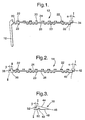
- a modular stair tread and nosing system 10 comprises a series of extruded aluminium components, in the example, a stair nosing 12, a tread plate 14 and a chamfer plate 16.
- Fig. 1 shows a stair nosing 12 that is generally L-shaped with a down-turned front piece 18 and an upper panel 20.
- a series of laterally-extending, integral, generally T-shaped ribs 22 protrude from upper panel surface 24; the T-shaping enabling ribs 22 to mechanically key with a non-slip infill 28 bonded to the upper panel surface, see Figs, 4 and 5.
- One rib 30 may be higher and generally rectilinear so as to provide a visible break in the infill.
- a series of laterally-extending generally dovetail-shaped ribs 23 protrude from lower panel surface 26.
- the upper panel terminates in rear edge 32 with an integral, down-turned hook 34 extending there along.
- the axis I-I of this hook is inclined at an angle ⁇ of approximately 15° to one side of the perpendicular to the plane of the upper panel.
- Fig. 2 shows a tread plate 14 that is generally similar to nosing upper panel 20 and like parts have the same references.
- front edge 36 of tread plate 14 has a width-wise extending, integral, upturned hook 38, complimentary to nosing hook 34; the axis II-II of this hook has an angle ⁇ of approximately 15° to the other side of the perpendicular to the plane of the tread plate.
- the rear edge 40 of tread plate 14 has an integral, down-turned hook 42; the axis I-I of this hook is inclined at an angle ⁇ of approximately 15° to the one side of the perpendicular to the plane of the tread plate.
- Fig. 3 shows a chamfer plate 16 that has an inclined, planar, upper surface 44 terminating in a rear edge 46.
- the under surface 48 is generally flat with a laterally-extending, dovetail-shaped groove 49. Upper surface may have transverse, slip-resistant ribbing (not shown).
- the front edge 50 of chamfer plate 16 has an integral, upturned hook 52, complimentary to nosing rear hook 34 or tread rear hook 42; the axis II-II of chamfer hook 52 has an angle ⁇ of approximately 15° to the other side of the perpendicular to the plane of the chamfer plate.
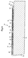
- a nosing plate 12 is fitted to a stair nose 54, a tread plate 14 is then fitted to nosing plate 12 by locating tread front hook 38 under nosing rear hook 34 and then rotating tread plate 14 clockwise to lift the rear of tread plate 14 sufficiently to enable the tread front hook 38 to engage under nosing rear hook 34, as shown in Fig. 4.
- Chamfer front hook 52 is similarly engaged under tread rear hook 42. This mode of interengagement is out of the common plane of the stair tread and enables the components to be fitted one-at-a-time in the confined space of a stair well as no planar movement of a component towards another component is needed.
- the components can be fixed to the stair 54 by a bonding agent (cement) 56, the dovetail-shaped lower surface ribs 23 and dovetail-shaped groove 49 providing a mechanical key and/or by fixings (such as nails or screws) through the components into the stair; only the rear of any component needs to be fixed, as it traps the front of the adjacent component.
- Components can be fixed to the stair one-at-a-time or as an assembled whole.
- the interconnected, complimentary angled hooks resist vertical movement between joined components as well as planar movements, such that all components do not need to be fixed to a surface; for example tread 14 could be left free, depending upon fixed nosing 12 and chamfer 16.
- the angle of the hooks improves the mechanical interlock between adjacent, interconnected, essentially rigid components without reliance on additional snap-fit features.
- Stair nosings and tread plates of differing lengths can be provided to enable a range of stair treads to be fitted using standardised component plates. Some applications may not require a chamfer plate, in which circumstance it will be noted that tread plate 14 will finish with a down turned hook 34; presenting a pleasing appearance and not forming a dirt trap.
- Non-inclined, hooks of the same orientation would function to keep component parts together as they are being assembled, but would not function to hold parts together vertically once they have been assembled. All component parts would need to be fixed to a floor. Whilst an included angle of 15° has been described, this could be any angle in the range 0° to 45°.
- the vertical/rotational engaging movement of a hook joint enables components to be engaged close to a vertical surface, for example the riser of the next stair, as no relative planar movement between components is required.
Abstract
Description
- This invention relates to floor panels and it particularly relates to modular floor panel systems, for example stair treads and nosings.
- It is known to provide panel systems to cover floors, stairs and the like structures; either as an original surface or to repair worn surfaces. The panel components for such systems are often provided with a non-slip upper surface and recent legislation in the United Kingdom can require non-slip surfaces in given circumstances. One application of such panels is as replacement stair treads and nosings, see for example our "PRO-TREAD™" panels, described at our website:- http://www.rocol.com/sitesafety/english/slipprevention/panels.php. These panels are custom-made for particular applications and can be quite large and cumbersome to fit.
- A known modular stair tread is the ALISPAR™ stair tread and nosing marketed by Magma Safety Products Limited , described at their website:- http://www.magmasafety.co.uk/alispar/alispar.htm. As shown, this stair tread and nosing comprises the following components:-
- an extruded aluminium nosing having a non-slip upper surface, a grooved undersurface and a dovetail mortise along the rear edge;
- an extruded aluminium tread having a non-slip upper surface, a grooved undersurface, a dovetail tenon along the front edge and a dovetail mortise along the rear edge;
and, - an extruded aluminium chamfer having a tapering upper surface, a grooved lower surface and a dovetail tenon along the front edge. The nosing, tread and chafer are jointed one to the other to form a complete stair tread system, which is then fixed to a stair. The dovetail joint provides a strong connection between the components but has the disadvantage that the components have to be assembled by sliding dovetail tenons lengthwise into dovetail mortises and this has to be done prior to installation and fixing to a stair; because there is no room to manoeuvre each component laterally with respect to another component in the confined space of a stairwell.
- Documents
EP-A2-0273517 [FERODO ] for "Flooring Edge Finisher" ,US-A-4840824 [DAVIS ] for "Stairtread Facings and a Co-Extrusion Method for their Manufacture" andGB-A-1578528 [ FERODO - Document
EP-A-1024234 [UNILIN ] for "Floor covering, consisting of hard floor panels and method of manufacturing such floor panels" wherein nose 9 of panel part 5 has to be introduced intogroove 10 ofpanel part 42 by a rotary movement of part 5 relative topart 42 and/or by relative planar movement of part 5 towardspart 42 for the parts to snap-fit one with the other [see para. 0097 and Figs 24 and 25]. - The problem with these prior art floor panels and stairtread facings is that the relative planar movement between parts to achieve for snap fit engagement limits installation of such panels and facings in confined spaces.
- It is an object of the present invention to provide a modular floor panel system wherein the component parts can be installed one-by-one in confined spaces.
- According to the present invention, a modular floor panel system comprises panel components each having:-
- i) a joint part extending along at least one panel edge;
- ii) the joint part shaped to interlock with a complimentary joint part extending along the meeting edge of an adjacent panel component; and,
- iii) the complimentary joint parts shaped to interconnect essentially by relative movement out of the common plane of the panel components.
- By "out of the common plane of" is meant any relative movement between panel components to interconnect joint parts in the plane of a floor on which the components are to be mounted, the "common plane", which relative movement does not consist of one panel meeting edge either being moved towards or along the meeting edge of an adjacent panel in the common plane.
- We have realised that, as modular floor panel components are generally fitted, such as by screwing and/or bonding, to a floor surface, the function of the joint need only be to locate one component part relative to another until some or all of the panel components have been fitted to a floor. This means that joints which can interconnect by relative non-planar movement, i.e. generally vertical and/or rotational, but which still resist relative planar movement of adjacent components away from one another can be used; for example a hook joint. This means that floor panel components of the present invention can be fitted in a stair well or other confined space, such a narrow hallway, component-by-component. Dovetail joints, such as that disclosed by the ALISPAR™ stair nosing and tread, do not meet this definition as they require one panel meeting edge to be moved along the meeting edge of an adjacent panel generally in the plane of the two components. Snap-fit joints require at least some relative planar movement towards one another.
- According to a preferred embodiment of the present invention, the joint parts are complementary, down-turned and up-turned hooks. The hooks may each have an included angle of between 0° and 45° to the perpendicular to the plane of the component; with a preferred angle of approximately 15°.
- According to a preferred application of the present invention, the system is for a modular stair tread and riser system which may comprises a stair nosing component, a tread plate component and/or a chamfer plate component.
- The above and further features of the present invention are illustrated, by way of example, in the Drawings, wherein:-
- Fig. 1
- is a side elevation of a stair nose component in accordance with a stair tread and nosing system in accordance with the present invention;
- Fig. 2
- is a similar view of a tread plate component for the system of Fig. 1;
- Fig. 3
- is a similar view of a chamfer plate component for the system of Fig. 1;
- Fig. 4
- is a side elevation of a stair tread and nosing system assembled from the components of Figs 1 to 3;
and, - Fig. 5
- is a perspective view of the stair tread and nosing system of Fig. 4.
- As shown by the figures a modular stair tread and
nosing system 10 comprises a series of extruded aluminium components, in the example, astair nosing 12, atread plate 14 and achamfer plate 16. - Fig. 1 shows a
stair nosing 12 that is generally L-shaped with a down-turnedfront piece 18 and anupper panel 20. A series of laterally-extending, integral, generally T-shaped ribs 22 protrude fromupper panel surface 24; the T-shaping enabling ribs 22 to mechanically key with anon-slip infill 28 bonded to the upper panel surface, see Figs, 4 and 5. Onerib 30 may be higher and generally rectilinear so as to provide a visible break in the infill. A series of laterally-extending generally dovetail-shaped ribs 23 protrude fromlower panel surface 26. The upper panel terminates inrear edge 32 with an integral, down-turnedhook 34 extending there along. The axis I-I of this hook is inclined at an angle α of approximately 15° to one side of the perpendicular to the plane of the upper panel. - Fig. 2 shows a
tread plate 14 that is generally similar to nosingupper panel 20 and like parts have the same references. However,front edge 36 oftread plate 14 has a width-wise extending, integral,upturned hook 38, complimentary tonosing hook 34; the axis II-II of this hook has an angle β of approximately 15° to the other side of the perpendicular to the plane of the tread plate. Therear edge 40 oftread plate 14 has an integral, down-turnedhook 42; the axis I-I of this hook is inclined at an angle α of approximately 15° to the one side of the perpendicular to the plane of the tread plate. - Fig. 3 shows a
chamfer plate 16 that has an inclined, planar,upper surface 44 terminating in arear edge 46. Theunder surface 48 is generally flat with a laterally-extending, dovetail-shaped groove 49. Upper surface may have transverse, slip-resistant ribbing (not shown). The front edge 50 ofchamfer plate 16 has an integral,upturned hook 52, complimentary to nosingrear hook 34 or treadrear hook 42; the axis II-II ofchamfer hook 52 has an angle β of approximately 15° to the other side of the perpendicular to the plane of the chamfer plate. - In use, a
nosing plate 12 is fitted to astair nose 54, atread plate 14 is then fitted tonosing plate 12 by locating treadfront hook 38 under nosingrear hook 34 and then rotatingtread plate 14 clockwise to lift the rear oftread plate 14 sufficiently to enable thetread front hook 38 to engage under nosingrear hook 34, as shown in Fig. 4. Chamferfront hook 52 is similarly engaged under treadrear hook 42. This mode of interengagement is out of the common plane of the stair tread and enables the components to be fitted one-at-a-time in the confined space of a stair well as no planar movement of a component towards another component is needed. - The components can be fixed to the
stair 54 by a bonding agent (cement) 56, the dovetail-shapedlower surface ribs 23 and dovetail-shaped groove 49 providing a mechanical key and/or by fixings (such as nails or screws) through the components into the stair; only the rear of any component needs to be fixed, as it traps the front of the adjacent component. Components can be fixed to the stair one-at-a-time or as an assembled whole. - The interconnected, complimentary angled hooks resist vertical movement between joined components as well as planar movements, such that all components do not need to be fixed to a surface; for
example tread 14 could be left free, depending upon fixed nosing 12 andchamfer 16. The angle of the hooks improves the mechanical interlock between adjacent, interconnected, essentially rigid components without reliance on additional snap-fit features. - Stair nosings and tread plates of differing lengths can be provided to enable a range of stair treads to be fitted using standardised component plates. Some applications may not require a chamfer plate, in which circumstance it will be noted that
tread plate 14 will finish with a down turnedhook 34; presenting a pleasing appearance and not forming a dirt trap. - Non-inclined, hooks of the same orientation would function to keep component parts together as they are being assembled, but would not function to hold parts together vertically once they have been assembled. All component parts would need to be fixed to a floor. Whilst an included angle of 15° has been described, this could be any angle in the range 0° to 45°. The vertical/rotational engaging movement of a hook joint, enables components to be engaged close to a vertical surface, for example the riser of the next stair, as no relative planar movement between components is required.
- Alternative joints could be used provided that complimentary joint parts can be inter-engaged by non-planar relative movement between panel components to interconnect complimentary joint parts. Although the present invention has been described in terms of stair panels, the invention is applicable to any floor panels to be assembled and fitted in a confined space; for example a narrow hallway.
Claims (9)
- A modular floor panel system comprising panel components (12, 14, 16) each having:-i) a joint part (34, 42) extending along at least one panel edge (32, 36, 40, 50);ii) the joint part shaped to interlock with a complimentary joint part (38, 52) extending along the meeting edge (36, 50) of an adjacent panel component;
characterised in that:iii) the complimentary joint parts (34, 42, 38, 52) are shaped to interconnect essentially by relative panel component movement out of the common plane of panel components (12, 14, 16). - A system as claimed in claim 1, wherein the joint parts are complementary, down-turned (34, 42) and up-turned (42, 52) hooks.
- A system as claimed in claim 2, wherein complementary hooks (34, 42, 38, 52) are interengageable on an axis (I-I, II-II) having an included angle (α, β) of between 0° and 45° to the perpendicular to the plane of the component (12, 14, 16).
- A system as claimed in claim 3, wherein the included angle (α, β) is approximately 15°.
- A system as claimed in any of claims 1 to 4, which is a modular stair tread and riser system.
- A modular stair tread and riser system as claimed in claim 5 and comprising stair nosing (12), tread plate (14) and/or chamfer plate (16) panel components.
- A system as claimed in claim 6, wherein:-i) the rear edge (32) of the stair nosing (12) has a hook (34);ii) the front edge (36) of the tread plate (14) has a complimentary hook (38);iii) the rear edge (40) of the tread plate has a hook (42); and,iv) the front edge (50) of the chamfer plate (16) has a complimentary hook (52).
- A system as claimed in claim 7, wherein:-i) the hooks (34, 42) at the rear edges (32, 40) of stair nosings (12) and tread plates (14) are down-turned;
and,ii) the hooks (38, 52) at the front edges (36, 50) of tread plates and chamfer plates (16) are up-turned. - A system as claimed in any of claims 6 to 8 wherein upper surfaces (24) of the stair nosing (12) and the tread plate (14) have a non-slip infill (28).
Applications Claiming Priority (1)
| Application Number | Priority Date | Filing Date | Title |
|---|---|---|---|
| GBGB0512736.0A GB0512736D0 (en) | 2005-06-22 | 2005-06-22 | Floor panels |
Publications (2)
| Publication Number | Publication Date |
|---|---|
| EP1736613A2 true EP1736613A2 (en) | 2006-12-27 |
| EP1736613A3 EP1736613A3 (en) | 2009-01-21 |
Family
ID=34855979
Family Applications (1)
| Application Number | Title | Priority Date | Filing Date |
|---|---|---|---|
| EP06253196A Withdrawn EP1736613A3 (en) | 2005-06-22 | 2006-06-21 | Floor panels |
Country Status (2)
| Country | Link |
|---|---|
| EP (1) | EP1736613A3 (en) |
| GB (1) | GB0512736D0 (en) |
Cited By (1)
| Publication number | Priority date | Publication date | Assignee | Title |
|---|---|---|---|---|
| US8806832B2 (en) | 2011-03-18 | 2014-08-19 | Inotec Global Limited | Vertical joint system and associated surface covering system |
Citations (5)
| Publication number | Priority date | Publication date | Assignee | Title |
|---|---|---|---|---|
| EP0011470A1 (en) * | 1978-11-13 | 1980-05-28 | Kabushiki Kaisha Naka Gijutsu Kenkyusho | Stair mat |
| EP0011469A1 (en) * | 1978-11-13 | 1980-05-28 | Kabushiki Kaisha Naka Gijutsu Kenkyusho | Stair mat |
| DE8713687U1 (en) | 1986-10-14 | 1987-12-23 | Ferodo Ltd., Manchester, Gb | |
| EP1024234A2 (en) | 1996-06-11 | 2000-08-02 | Unilin Beheer B.V. | Floor covering, consisting of hard floor panels and method for manufacturing such floor panels |
| GB2365880A (en) | 2000-06-23 | 2002-02-27 | Humphries Nigel John | Imitation wood covering formed from a plurality ofinterlocking plastics planks |
Family Cites Families (2)
| Publication number | Priority date | Publication date | Assignee | Title |
|---|---|---|---|---|
| DE19933343A1 (en) * | 1999-07-16 | 2001-02-01 | Ledermann & Co | Method of laying floor tiles consists of interlocking tongues and grooves in adjoining surface edges |
| US7559177B2 (en) * | 2001-11-08 | 2009-07-14 | Pergo (Europe) Ab | Smooth flooring transitions |
-
2005
- 2005-06-22 GB GBGB0512736.0A patent/GB0512736D0/en not_active Ceased
-
2006
- 2006-06-21 EP EP06253196A patent/EP1736613A3/en not_active Withdrawn
Patent Citations (5)
| Publication number | Priority date | Publication date | Assignee | Title |
|---|---|---|---|---|
| EP0011470A1 (en) * | 1978-11-13 | 1980-05-28 | Kabushiki Kaisha Naka Gijutsu Kenkyusho | Stair mat |
| EP0011469A1 (en) * | 1978-11-13 | 1980-05-28 | Kabushiki Kaisha Naka Gijutsu Kenkyusho | Stair mat |
| DE8713687U1 (en) | 1986-10-14 | 1987-12-23 | Ferodo Ltd., Manchester, Gb | |
| EP1024234A2 (en) | 1996-06-11 | 2000-08-02 | Unilin Beheer B.V. | Floor covering, consisting of hard floor panels and method for manufacturing such floor panels |
| GB2365880A (en) | 2000-06-23 | 2002-02-27 | Humphries Nigel John | Imitation wood covering formed from a plurality ofinterlocking plastics planks |
Cited By (3)
| Publication number | Priority date | Publication date | Assignee | Title |
|---|---|---|---|---|
| US8806832B2 (en) | 2011-03-18 | 2014-08-19 | Inotec Global Limited | Vertical joint system and associated surface covering system |
| US9103126B2 (en) | 2011-03-18 | 2015-08-11 | Inotec Global Limited | Vertical joint system and associated surface covering system |
| US10000935B2 (en) | 2011-03-18 | 2018-06-19 | Inotec Global Limited | Vertical joint system and associated surface covering system |
Also Published As
| Publication number | Publication date |
|---|---|
| GB0512736D0 (en) | 2005-07-27 |
| EP1736613A3 (en) | 2009-01-21 |
Similar Documents
| Publication | Publication Date | Title |
|---|---|---|
| US10240349B2 (en) | Mechanical locking system for floor panels | |
| CA2809984C (en) | Covering panel and method for assembling a plurality of same | |
| US20160340910A1 (en) | Floating floor system, floor panel, and installation method for the same | |
| CA2699214C (en) | Stair tread overlay and method | |
| KR102083655B1 (en) | Mechanical locking system for floor panels | |
| US7784237B2 (en) | Transition molding and installation methods therefor | |
| US20050150182A1 (en) | Transition molding | |
| EP4227474A1 (en) | Mechanical locking system for floor panels | |
| US20070277473A1 (en) | Interlocking interior trim | |
| US20130232905A2 (en) | Mechanical locking system for floor panels | |
| US20060254171A1 (en) | Wall paneling assembly and system | |
| US20080263983A1 (en) | Flush or near-flush flooring transitions | |
| CN110088413A (en) | For the plate of wall board and the three-D pattern of ceiling sheet, installs fixture and wall covering or ceiling covering | |
| US20080263979A1 (en) | Interlocking interior trim | |
| WO2008088239A1 (en) | Connection joint for structural panels | |
| EP1736613A2 (en) | Floor panels | |
| US6374562B1 (en) | Adjustably sizeable raised panel system for stairs and method for forming and installing same | |
| CN113631782A (en) | Kit comprising a coupling element, a first building element and a building panel and method of assembling said kit | |
| US20120011786A1 (en) | Structural stringer for stairways | |
| WO2018095504A1 (en) | Drywall profile | |
| EP1516977A1 (en) | Panel, in particular for wood floors | |
| EP4133139A1 (en) | Arrangements for stairs, in particular a stair nose cover member, and a set comprising the cover member | |
| RU83789U1 (en) | COMBINED FLOORS | |
| RU71353U1 (en) | CONSTRUCTION PANEL ASSEMBLY ASSEMBLY | |
| BE1019339A3 (en) |
Legal Events
| Date | Code | Title | Description |
|---|---|---|---|
| PUAI | Public reference made under article 153(3) epc to a published international application that has entered the european phase |
Free format text: ORIGINAL CODE: 0009012 |
|
| AK | Designated contracting states |
Kind code of ref document: A2 Designated state(s): AT BE BG CH CY CZ DE DK EE ES FI FR GB GR HU IE IS IT LI LT LU LV MC NL PL PT RO SE SI SK TR |
|
| AX | Request for extension of the european patent |
Extension state: AL BA HR MK YU |
|
| 17P | Request for examination filed |
Effective date: 20070521 |
|
| PUAL | Search report despatched |
Free format text: ORIGINAL CODE: 0009013 |
|
| AK | Designated contracting states |
Kind code of ref document: A3 Designated state(s): AT BE BG CH CY CZ DE DK EE ES FI FR GB GR HU IE IS IT LI LT LU LV MC NL PL PT RO SE SI SK TR |
|
| AX | Request for extension of the european patent |
Extension state: AL BA HR MK RS |
|
| AKX | Designation fees paid |
Designated state(s): GB IE NL |
|
| REG | Reference to a national code |
Ref country code: DE Ref legal event code: 8566 |
|
| 17Q | First examination report despatched |
Effective date: 20091215 |
|
| RAP1 | Party data changed (applicant data changed or rights of an application transferred) |
Owner name: ILLINOIS TOOL WORKS INC. |
|
| STAA | Information on the status of an ep patent application or granted ep patent |
Free format text: STATUS: THE APPLICATION IS DEEMED TO BE WITHDRAWN |
|
| 18D | Application deemed to be withdrawn |
Effective date: 20120918 |